EP3456599B1 - Überwachung von fahrern und der äusseren umgebung für fahrzeuge - Google Patents
Überwachung von fahrern und der äusseren umgebung für fahrzeuge Download PDFInfo
- Publication number
- EP3456599B1 EP3456599B1 EP17210132.1A EP17210132A EP3456599B1 EP 3456599 B1 EP3456599 B1 EP 3456599B1 EP 17210132 A EP17210132 A EP 17210132A EP 3456599 B1 EP3456599 B1 EP 3456599B1
- Authority
- EP
- European Patent Office
- Prior art keywords
- driver
- data
- external environment
- monitoring module
- vehicle
- Prior art date
- Legal status (The legal status is an assumption and is not a legal conclusion. Google has not performed a legal analysis and makes no representation as to the accuracy of the status listed.)
- Active
Links
Images


Classifications
-
- G—PHYSICS
- G08—SIGNALLING
- G08G—TRAFFIC CONTROL SYSTEMS
- G08G1/00—Traffic control systems for road vehicles
- G08G1/16—Anti-collision systems
-
- B—PERFORMING OPERATIONS; TRANSPORTING
- B60—VEHICLES IN GENERAL
- B60W—CONJOINT CONTROL OF VEHICLE SUB-UNITS OF DIFFERENT TYPE OR DIFFERENT FUNCTION; CONTROL SYSTEMS SPECIALLY ADAPTED FOR HYBRID VEHICLES; ROAD VEHICLE DRIVE CONTROL SYSTEMS FOR PURPOSES NOT RELATED TO THE CONTROL OF A PARTICULAR SUB-UNIT
- B60W50/00—Details of control systems for road vehicle drive control not related to the control of a particular sub-unit, e.g. process diagnostic or vehicle driver interfaces
- B60W50/08—Interaction between the driver and the control system
- B60W50/14—Means for informing the driver, warning the driver or prompting a driver intervention
- B60W50/16—Tactile feedback to the driver, e.g. vibration or force feedback to the driver on the steering wheel or the accelerator pedal
-
- G—PHYSICS
- G06—COMPUTING OR CALCULATING; COUNTING
- G06V—IMAGE OR VIDEO RECOGNITION OR UNDERSTANDING
- G06V20/00—Scenes; Scene-specific elements
- G06V20/50—Context or environment of the image
- G06V20/56—Context or environment of the image exterior to a vehicle by using sensors mounted on the vehicle
- G06V20/58—Recognition of moving objects or obstacles, e.g. vehicles or pedestrians; Recognition of traffic objects, e.g. traffic signs, traffic lights or roads
-
- G—PHYSICS
- G06—COMPUTING OR CALCULATING; COUNTING
- G06V—IMAGE OR VIDEO RECOGNITION OR UNDERSTANDING
- G06V20/00—Scenes; Scene-specific elements
- G06V20/50—Context or environment of the image
- G06V20/59—Context or environment of the image inside of a vehicle, e.g. relating to seat occupancy, driver state or inner lighting conditions
- G06V20/597—Recognising the driver's state or behaviour, e.g. attention or drowsiness
-
- B—PERFORMING OPERATIONS; TRANSPORTING
- B60—VEHICLES IN GENERAL
- B60W—CONJOINT CONTROL OF VEHICLE SUB-UNITS OF DIFFERENT TYPE OR DIFFERENT FUNCTION; CONTROL SYSTEMS SPECIALLY ADAPTED FOR HYBRID VEHICLES; ROAD VEHICLE DRIVE CONTROL SYSTEMS FOR PURPOSES NOT RELATED TO THE CONTROL OF A PARTICULAR SUB-UNIT
- B60W50/00—Details of control systems for road vehicle drive control not related to the control of a particular sub-unit, e.g. process diagnostic or vehicle driver interfaces
- B60W50/08—Interaction between the driver and the control system
- B60W50/14—Means for informing the driver, warning the driver or prompting a driver intervention
- B60W2050/143—Alarm means
-
- B—PERFORMING OPERATIONS; TRANSPORTING
- B60—VEHICLES IN GENERAL
- B60W—CONJOINT CONTROL OF VEHICLE SUB-UNITS OF DIFFERENT TYPE OR DIFFERENT FUNCTION; CONTROL SYSTEMS SPECIALLY ADAPTED FOR HYBRID VEHICLES; ROAD VEHICLE DRIVE CONTROL SYSTEMS FOR PURPOSES NOT RELATED TO THE CONTROL OF A PARTICULAR SUB-UNIT
- B60W50/00—Details of control systems for road vehicle drive control not related to the control of a particular sub-unit, e.g. process diagnostic or vehicle driver interfaces
- B60W50/08—Interaction between the driver and the control system
- B60W50/14—Means for informing the driver, warning the driver or prompting a driver intervention
- B60W2050/146—Display means
-
- B—PERFORMING OPERATIONS; TRANSPORTING
- B60—VEHICLES IN GENERAL
- B60W—CONJOINT CONTROL OF VEHICLE SUB-UNITS OF DIFFERENT TYPE OR DIFFERENT FUNCTION; CONTROL SYSTEMS SPECIALLY ADAPTED FOR HYBRID VEHICLES; ROAD VEHICLE DRIVE CONTROL SYSTEMS FOR PURPOSES NOT RELATED TO THE CONTROL OF A PARTICULAR SUB-UNIT
- B60W2420/00—Indexing codes relating to the type of sensors based on the principle of their operation
- B60W2420/40—Photo, light or radio wave sensitive means, e.g. infrared sensors
- B60W2420/403—Image sensing, e.g. optical camera
-
- B—PERFORMING OPERATIONS; TRANSPORTING
- B60—VEHICLES IN GENERAL
- B60W—CONJOINT CONTROL OF VEHICLE SUB-UNITS OF DIFFERENT TYPE OR DIFFERENT FUNCTION; CONTROL SYSTEMS SPECIALLY ADAPTED FOR HYBRID VEHICLES; ROAD VEHICLE DRIVE CONTROL SYSTEMS FOR PURPOSES NOT RELATED TO THE CONTROL OF A PARTICULAR SUB-UNIT
- B60W2420/00—Indexing codes relating to the type of sensors based on the principle of their operation
- B60W2420/40—Photo, light or radio wave sensitive means, e.g. infrared sensors
- B60W2420/408—Radar; Laser, e.g. lidar
-
- B—PERFORMING OPERATIONS; TRANSPORTING
- B60—VEHICLES IN GENERAL
- B60W—CONJOINT CONTROL OF VEHICLE SUB-UNITS OF DIFFERENT TYPE OR DIFFERENT FUNCTION; CONTROL SYSTEMS SPECIALLY ADAPTED FOR HYBRID VEHICLES; ROAD VEHICLE DRIVE CONTROL SYSTEMS FOR PURPOSES NOT RELATED TO THE CONTROL OF A PARTICULAR SUB-UNIT
- B60W2520/00—Input parameters relating to overall vehicle dynamics
- B60W2520/06—Direction of travel
-
- B—PERFORMING OPERATIONS; TRANSPORTING
- B60—VEHICLES IN GENERAL
- B60W—CONJOINT CONTROL OF VEHICLE SUB-UNITS OF DIFFERENT TYPE OR DIFFERENT FUNCTION; CONTROL SYSTEMS SPECIALLY ADAPTED FOR HYBRID VEHICLES; ROAD VEHICLE DRIVE CONTROL SYSTEMS FOR PURPOSES NOT RELATED TO THE CONTROL OF A PARTICULAR SUB-UNIT
- B60W2540/00—Input parameters relating to occupants
- B60W2540/043—Identity of occupants
-
- B—PERFORMING OPERATIONS; TRANSPORTING
- B60—VEHICLES IN GENERAL
- B60W—CONJOINT CONTROL OF VEHICLE SUB-UNITS OF DIFFERENT TYPE OR DIFFERENT FUNCTION; CONTROL SYSTEMS SPECIALLY ADAPTED FOR HYBRID VEHICLES; ROAD VEHICLE DRIVE CONTROL SYSTEMS FOR PURPOSES NOT RELATED TO THE CONTROL OF A PARTICULAR SUB-UNIT
- B60W2540/00—Input parameters relating to occupants
- B60W2540/22—Psychological state; Stress level or workload
-
- B—PERFORMING OPERATIONS; TRANSPORTING
- B60—VEHICLES IN GENERAL
- B60W—CONJOINT CONTROL OF VEHICLE SUB-UNITS OF DIFFERENT TYPE OR DIFFERENT FUNCTION; CONTROL SYSTEMS SPECIALLY ADAPTED FOR HYBRID VEHICLES; ROAD VEHICLE DRIVE CONTROL SYSTEMS FOR PURPOSES NOT RELATED TO THE CONTROL OF A PARTICULAR SUB-UNIT
- B60W2540/00—Input parameters relating to occupants
- B60W2540/26—Incapacity
Definitions
- the present invention relates generally to monitoring drivers and external environment for vehicles and particularly to monitoring driver state, a driving pattern of a driver in a vehicle, and the external environment.
- Modern vehicles are generally equipped with various types of monitoring systems, such as cameras, or video recorders to monitor surrounding environment of vehicles and provide a driver of a vehicle with useful data regarding the surrounding environment for improved driving.
- monitoring systems may be installed, for instance, on a roof of the vehicle or on the front portion, back portion of the vehicle to have a broad view of the surrounding environment and capture data associated with objects, pedestrians or vehicles within the surrounding environment.
- the monitoring systems may also monitor the driver of the vehicle for facial pose and gaze. For instance, the driver may be monitored for orientation of the face and the gaze to be in a forward direction and determine if the driver is paying attention on the road. The collected data is then subjected to processing to derive meaningful information that may be used in assisting the driver for navigation, changing lanes, and averting a potential collision. An event, such as an approaching vehicle, a pedestrian on the road may be detected and a warning may be issued to the driver to help the driver initiate a precautionary action.
- WO2016209423A1 discloses a cognitive-driver-assist system that varies the warning- intensity of a warning or varies the degree to which the system takes over control of a host- vehicle driven by an operator.
- the warning-intensity and the take-over authority are determined in accordance with a measure of how aware the operator is of a particular object proximate to or in the travel-path of the host-vehicle.
- US application no. US20160297433A1 disclosed a long term driving danger prediction system and methods to assist a driver with a dangerous condition by combining several sensor modalities available on modern cars to detect traffic participants as well as static elements. Another US application no.
- US20160009295A1 relates to an on-vehicle situation detection apparatus and method, which grasp a driver's mental and physical condition to determine whether or not a driver drives a vehicle with safety and induce the driver to drive the vehicle with safety in various ways when the driver is determined to be not in a safe driving state so as to protect the driver. Further, it can detect situations in real time through rapid calculation since a considerable time is required when a great deal of data is collected from a plurality of sensors and the situations are detected according to technological development.
- GB2528084 provided a hazard notification system for a vehicle operable by a driver, the notification system comprising: an input to receive information of a current event; a database comprising a plurality of records, a processor arranged to determine a record from the database, by comparing the received information associated with the current event to the information associated with the earlier events, and retrieve a response of the driver corresponding to the determined record from the database; and an output arranged to notify the driver of the current event in dependence on the response of the driver corresponding to the determined record.
- an ADAS includes a driver monitoring module, an exterior monitoring module, a processor coupled to the driver monitoring module and the exterior monitoring module, and a warning generating module coupled to the processor.
- the driver monitoring module may be positioned facing a driver to monitor a driver state, such as drowsiness, sleepiness, and inattentiveness of the driver.
- the driver state may be monitored based on various factors, such as blinking of eyes, head movement, color of skin, frowning, eye ball movements. For instance, a closing of eyes more than 3 seconds may be classified as drowsiness, and a high degree of head movement may be classified as inattentiveness.
- the exterior monitoring module facing the road, captures data regarding objects, lane markings, potholes, speed signs, and traffic conditions from external environment.
- the exterior monitoring module may also monitor driving pattern of the driver. For example, whether the driver is driving the vehicle in line with the lanes of the road or driving inconsistently and frequently crossing the lanes and the boundaries of the road.
- the exterior monitoring module adjusts a Region of Interest (ROI) of the view of the road or external environment based on data associated with a path of travel of the vehicle, comprising at least one of a driver indication for a turn, a steering wheel angle change, a path travelled by the vehicle, and a Global Positioning System (GPS) signal.
- ROI Region of Interest
- GPS Global Positioning System
- the data captured from the driver monitoring module and the exterior monitoring module are sent to the processor.
- the processor processes the data to detect occurrence of an event, for instance, an approaching pedestrian or a vehicle, an object on the road.
- the processor signals the warning generating module to generate a warning based on the detected event. For instance, a continuous beep sound or a voice based alert may be generated to alert the driver about the event.
- intensity of the warning is varied based on the data received from at least one of the exterior monitoring module and the driver monitoring module. For instance, when the vehicle is approaching a pedestrian, who is at a distance of around 250 meters, and the driver is attentive, then volume of the beep sound may be low. However, when the vehicle is approaching the pedestrian with speed, the volume of the beep sound is increased until a preventive action is taken to avert a collision or until the pedestrian reaches a safe place that is outside the view of the exterior monitoring module.
- the driver monitoring module, the exterior monitoring module, the processor, and the warning generating module may operate in real-time to capture and process the data to generate the warning. Further, the intensity of the warning is also varied in real-time based on criticality of the event.
- the present invention has been described with reference to an integrated ADAS comprising the modules, the present invention may also be applicable to monitoring driver and the external environment by the modules placed at different areas within an autonomous vehicle, wherein the modules are communicatively coupled to each other.
- the present invention provides efficient techniques for detecting events and alerting a driver.
- the techniques provide adaptive warning to the driver of the vehicle, wherein intensity level of the warning is varied based on driver state data, driving pattern data and the external environment data. Further, the events detected are accurate and the warning generated are relevant to a specific situation to enable the driver respond aptly to the events thereby enhancing driver safety.
- the environment 100 includes a vehicle 102 moving or being driven on a road 104.
- the vehicle 102 may be a car, a jeep, a truck, a bus, or a three-wheeler vehicle.
- the vehicle 102 may have parts like steering wheel, tires, brake, engine, carburetor, doors, horn, lights, etc. not shown in the figure.
- the vehicle 102 may be provided with physical actuators connected to critical function parts like brakes, engine control unit, steering wheel, horn and lights.
- the vehicle 102 further includes an Advanced Driver Assistance System (ADAS) 106 positioned such that the ADAS 106 may monitor facial expressions of the driver and may monitor the external environment.
- ADAS Advanced Driver Assistance System
- the ADAS 106 may be positioned close to the rear view mirror of the vehicle 102. It would be noted that, although the ADAS 106 is shown positioned near the rear view mirror, the ADAS 106 may be positioned at other places with in the vehicle 102. For instance, the ADAS 106 may be positioned on one of a windshield behind an internal rear view mirror, an "A" pillar of the vehicle 102, and on a dashboard.
- the ADAS 106 may have various modules to collect external data, such as data associated with roads, pedestrians, objects, road edges, lane marking, potential collision, speed signs, potholes, vehicles, and a driving pattern of the driver on the road. Additionally, the ADAS may monitor driving pattern of the driver such as whether the driving is in line with the lanes and boundaries of a road. Further, the modules may also capture data related to driver state, such as facial expressions and features, blink rate of eyes, eyeball movement, opening of the eye, and head movement of the driver. The ADAS 106 may also warn the driver corresponding to events, such as a pedestrian crossing the road, or a cyclist in front of the vehicle.
- external data such as data associated with roads, pedestrians, objects, road edges, lane marking, potential collision, speed signs, potholes, vehicles, and a driving pattern of the driver on the road. Additionally, the ADAS may monitor driving pattern of the driver such as whether the driving is in line with the lanes and boundaries of a road. Further, the modules may also capture data
- ADAS 106 may have the modules placed at different positions within the vehicle.
- the module for monitoring the driver may be coupled to the windscreen and the module to generate the warning may be coupled to the A-pillar.
- Such components may either be connected through a wired connection or through a wireless communication to communicate and share data.
- the ADAS 106 may be connected to an external server (not shown in figure) through a wireless network, such as a datacenter for cloud backup and data archiving purpose.
- a wireless network such as a datacenter for cloud backup and data archiving purpose.
- information associated with occurrence of an event and preventive action taken by the driver may be recorded for a predefined time span of 1 minute, 30 seconds, or 5 seconds and relayed to the datacenter.
- Such information may be stored within the datacenter and may be used for analyzing driver pattern during the events and providing useful information to other drivers in similar situations. Also, the information may be utilized for validating insurance claims or insurance premium calculations.
- the ADAS 106 may be connected to the actuators as mentioned above. This helps to take over control of these critical function parts in an event of user failing to react.
- FIG. 2A illustrates various modules of the ADAS 106, in accordance with an implementation of the present invention.
- the ADAS 106 includes an exterior monitoring module 202, a driver monitoring module 206, a ranging module 204, a processor 208, a memory 210 and a warning generation module 212.
- the processor 208 may be communicably connected to the exterior monitoring module 202, the driver monitoring module 206, and the ranging module 204.
- the processor 208 may also be communicably connected to a memory 210 and the warning generation module 212.
- the modules such as the exterior monitoring module 202, the driver monitoring module 206, the ranging module 204, and the driver monitoring module 206 may include routines, programs, objects, components, data structures, and the like, which perform particular tasks or implement particular abstract data types.
- the modules may further include modules that supplement applications on the ADAS 106, for example, modules of an operating system. Further, the modules can be implemented in hardware, instructions executed by a processing unit, or by a combination thereof.
- the modules may be machine-readable instructions which, when executed by a processor/processing unit, perform any of the described functionalities.
- the machine-readable instructions may be stored on an electronic memory device, hard disk, optical disk or other machine-readable storage medium or non-transitory medium.
- the machine-readable instructions can also be downloaded to the storage medium via a network connection.
- the exterior monitoring module 202 is configured to be facing out of the vehicle 102. This configuration helps the exterior monitoring module 202 to capture data from environment external to the vehicle 102.
- the exterior monitoring module 202 may include a stereo camera 202A and a long range narrow field camera 202A.
- the stereo camera 202A may be a dual lens camera having a short range. This helps the stereo camera 202A to capture data within a short distance of the vehicle 102.
- the stereo camera 202A captures the nearby objects, events and data.
- the long range narrow field camera 202B is configured to capture events at a farther distance and hence captures objects, events and data at a longer distance from the vehicle 102.
- the stereo camera 202A and the long range narrow camera 202B may be configured to adjust autofocus with the changing environment.
- the capturing ranges of the stereo camera 202A and the long range narrow field camera 202B may overlap to capture maximum data from external environment.
- the exterior monitoring module 202 is configured to shift its region of interest. The shifting of the region of interest may be based upon a condition of path of travel of the vehicle 102. Details of shifting of region of interest will be described in detail in conjunction with FIGs 4A-4
- the driver monitoring module 206 is positioned to face the driver of the vehicle 102 and monitors driver state of the driver.
- the driver state is determined utilizing driver's eye gaze, facial expressions and head movement.
- Various driver states that may be determined by the driver monitoring camera are fatigue, sleepiness, anger, happy, jolly, sad, neutral, etc.
- the driver monitoring module 206 is capable of determining multiple driver states.
- the driver monitoring module 206 may be a charged coupled device camera, or a Complementary Metal Oxide Semiconductor (CMOS) camera.
- CMOS Complementary Metal Oxide Semiconductor
- the ranging module 204 used for determining distance to objects may be one of a light detection and ranging (LiDAR) unit, a radio detection and ranging (RADAR), a sonic detection and ranging (SODAR), and a sound navigation and ranging (SONAR).
- LiDAR light detection and ranging
- RADAR radio detection and ranging
- SODAR sonic detection and ranging
- SONAR sound navigation and ranging
- the warning generation module 212 may include an audio, visual, or haptic warning interfaces.
- the warning generation module 212 may include a Light Emitting Diode (LED) display, a Liquid Crystal Display (LCD), a plasma display, a warning light emitter, a speaker, a haptic feedback module, or a combination thereof.
- LED Light Emitting Diode
- LCD Liquid Crystal Display
- plasma display a warning light emitter
- speaker a speaker
- haptic feedback module or a combination thereof.
- the processor 208 may be configured to fetch and execute computer-readable instructions stored in a memory.
- the processor 208 may be implemented as one or more microprocessors, microcomputers, microcontrollers, digital signal processors, central processing units, state machines, logic circuitries, and/or any devices that manipulate signals based on operational instructions.
- the functions of the various elements shown in the figure, including any functional blocks labelled as "processor(s)", may be provided through the use of dedicated hardware as well as hardware capable of executing software in association with appropriate software.
- the processor 208 and other modules like the exterior monitoring module 202, the driver monitoring module 206, the ranging module 204 and the warning generation module 212 as described above may be implemented as hardware or software. If such modules are implemented in software, one or more processors of the associated computing system that performs the operation of the module direct the operation of the computing system in response to having executed computer-executable instructions. For example, such computer-executable instructions may be embodied on one or more computer-readable media that form a computer program product. In another implementation, the processor 208 may also be connected to GPS, indicator of the vehicle 102 or pre-fed path of the route to be covered by the vehicle 102.
- a memory 210 may be utilized to store the collected external environment and internal environment data collected.
- the memory 210 may be without limitation, memory drives, removable disc drives, etc., employing connection protocols such as serial advanced technology attachment (SATA), integrated drive electronics (IDE), IEEE-1394, universal serial bus (USB), fiber channel, small computer systems interface (SCSI), etc.
- the memory drives may further include a drum, magnetic disc drive, magneto-optical drive, optical drive, redundant array of independent discs (RAID), solid-state memory devices, solid-state drives, etc.
- the exterior monitoring module 202 may continuously record the surrounding environment of the vehicle 102 and provide the input to the processor 208.
- the surrounding environment may include a pedestrian crossing the road and about 200 meters away from the vehicle 102, two vehicles ahead of the vehicle 102 at distances 210 meters and 220 meters and a cyclist on a left lane at a distance of 225 meters from the vehicle 102.
- the objects in the surrounding environment, such as the pedestrian, the two vehicles, and the cyclist are continuously monitored by the exterior monitoring module 202 in real-time and sent to the processor 208.
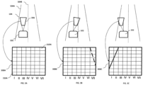
- the exterior monitoring module 202 may detect the lanes or boundaries of a road or path travelled by the vehicle 102, as shown in Figs 3A, 3B and 3C .
- the figure 3A illustrates the road 104 travelled by the vehicle 102, and the Region of Interest (ROI) 306 as focused by the exterior monitoring module 202.
- the exterior monitoring module 202 may move the ROI 306 to capture the boundary of the road 104 and a lane present on the road 104.
- the frames 308A, 308B, and 308C illustrate the ROI 306 as captured by the exterior monitoring module 202.
- the shape of the ROI is adjusted to adapt to the changing external environment data.
- the shape of the ROI may be changed to fit to a particular portion of a curved road.
- size change may be effected to cover cross roads conditions.
- the ROI may be moved in a linear direction from left to right or from right to left.
- the ROI may be moved in a non-linear manner from one point to another point depending upon the external conditions.
- the ROI may be moved from a first point on a straight road to a second point on an elevated road, where the second point is above the plane of the first point.
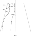
- the exterior monitoring module 202 may capture the driving pattern of the driver based on the area of the road 104 covered by the vehicle 102 during travel. For instance, the exterior monitoring module 202 may capture when the vehicle is driven along the lane or the boundary of the road 104, wherein the area covered by the vehicle 102 completely aligns with one of the lane and the boundary of the road 104.
- the vehicle may be driven in a zig-zag manner that does not align with the one of the road boundary and the lane and frequently crosses the lanes.
- the vehicle 102 may be driven in a wave-manner as illustrated in the Fig. 3D .
- the driving pattern is indicative of the manner in which the vehicle 102 is being driven on the road 104. For instance, when a driver is attentive then the driver is likely to drive in alignment with the lane or the boundary and when the driver is inattentive, drowsy, or under the influence of a drug, the driver may drive inconsistently and not in alignment with the lane or the boundary.
- driver state data is captured by the driver monitoring module 204.
- the driver monitoring module 206 may continuously record facial expressions of the driver for eye gaze, blink rate of eyelids, change in skin tone, nostrils, jaw movements, frowning, baring teeth, movement of cheeks, movement of lips and head movements when the driver is driving the vehicle on the road 104.
- the continuous recording of the driver state is fed to the processor 208.
- the processor 208 receives the data from the exterior monitoring module 202 and the driver monitoring module 204 and processes the received data. The processing of the data as received by the processor 208 is explained in conjunction with the description of FIG. 4 .
- FIG. 4 illustrates various engines of the processor 208, in accordance with an implementation of the present invention.
- Engines may be microcontrollers functioning in tandem with each other to achieve coordinated output from the processor 208.
- the processor 208 includes a data receiving engine 402, a determination engine 404, a rating engine 406, a weightage engine 408, and a driving pattern engine 410.
- the determination engine 404 may be communicably connected to the data receiving engine 402, the rating engine 406, the weightage engine 408 and the driving pattern engine 410.
- the engines such as the data receiving engine 402, the determination engine 404, the rating engine 406, the weightage engine 408 and the driving pattern engine 410 may include routines, programs, objects, components, data structure and the like, which perform particular tasks or implement particular abstract data types.
- the engines may further include engines that supplement applications on the processor 208, for example, modules of an operating system.
- the engine can be implemented in hardware, instructions executed by a processing unit, or by a combination thereof.
- the engines may be machine-readable instructions which, when executed by a processor/processing unit, perform any of the described functionalities.
- the machine-readable instructions may be stored on an electronic memory device, hard disk, optical disk or other machine-readable storage medium or non-transitory medium.
- the machine-readable instructions can also be downloaded to the storage medium via a network connection.
- the data receiving engine 402 is communicably connected to the determination engine 404, the driving pattern engine 410 and the weightage engine 408.
- the data receiving engine 402 forwards the data received simultaneously to the determination engine 404, the weightage engine 408 and the driving pattern engine 410 for simultaneous processing.
- the determination engine 404 may also be communicably connected to the rating engine 406.
- the data receiving engine 402 may receive data associated with path of travel of the vehicle 102.
- the data regarding the changes may be generated by steering angle change more than a predetermined threshold, indicator switched on by the driver, path change like a curving road or crossroads or lane change as per GPS or on the basis of a pre-fed route in navigation system of the vehicle.
- the data receiving engine 402 may also be configured to receive data from a vehicle console or an Electronic Control Unit (ECU) of the vehicle 102.
- the ECU may communicate data regarding changes the driving path of the vehicle 102.
- the data may be then forwarded to the determination engine 404.
- the determination engine 404 may analyze the change data and generate a signal to be sent to the external monitoring module 202 to change its focus position in order to change ROI.
- the signal generated may be received by the external monitoring module 202 through an interface (not shown in figure).
- the interface may be configured to interpret the information within the signal and change the orientation of the external monitoring module 202 in order to change the ROI as per the change data.
- the ADAS 106 may include low power DC motors (not shown in figure) to help in movement of the external monitoring module 202.
- the ROI may be shifted without a change in the orientation of the exterior monitoring module 102.
- the exterior monitoring module 102 may change the focal length or zone to adjust the ROI.
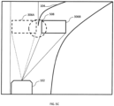
- FIGs. 5A-5C illustrate shifting of the ROI, in accordance to an embodiment of the present invention.
- FIG. 5A depicts shifting of region of interest 306A (similar to region of interest 306) based on the indicator initiation by the driver of the vehicle 102. As shown, if the driver of the vehicle 102 faces a situation wherein the driver has to shift to its existing lane 502 to one on the left 504, the driver may turn on the indicator. Upon the turning on of the indicator, the data receiving engine 402 may receive this information from the vehicle console or the ECU and direct the exterior monitoring module 102 to shift or adjust the ROI 306A. The ROI 306A may then be shifted a new ROI 306B.
- the exterior monitoring module 102 may monitor the external environment data for the new ROI 306 B.
- the region of interest 306A may also be shifted based on the steering wheel angle change. If the steering wheel angle is changed beyond a threshold value, the region of interest 306A is shifted to new region of interest 306B.
- the region of interest 306A is adjusted in a perspective manner.
- the ROI 306A is expanded to new region of interest 306B to cover more area of the road so as to monitor traffic on other roads and detect if other vehicles approach the vehicle 102 for a potential collision.
- region of interest 306A may also be shifted based on pre-fed route input, as illustrated by FIG. 5C .
- the driver may input a route into the vehicle 102 navigation console. Based on the navigation route, in case the vehicle 102 needs to take a right lane from a bifurcation 508 on road 104, as shown in the FIG. 5C , then the region of interest 306A is gradually shifted to a new region of interest 306B.
- the region of interest 306A may be gradually shifted and not suddenly as may be the case, with indicator initiation or steering wheel angle change. Thereafter, the external environment data is provided to the processor 208.
- the data receiving engine 402 of the processor 208 receives the external environment data, and the driving pattern data from the exterior monitoring module 202 and the driver state data from the driver monitoring module 206.
- the combined data collected by the data receiving engine 402 may be saved in the memory 210 connected to the processor 208. Further, this data may also be sent to the determination engine 404, the weightage engine 408 and the driving pattern engine 410 for simultaneous processing.
- the determination engine 404 may utilize various techniques. In one example, pixel mapping as shown in FIGs. 3A-3D , may be utilized for calculating the driving pattern. The determination engine 404 determines extremes of the road 104A and 104B. From the image captured, a pixel map 308A may be generated, that may be made up of multiple pixels 310A-310A.
- Each pixel image may have multiple pixel rows for e.g. I, II, III, IV, V, VI, VII within which pixels 310A-310N lines. It should be appreciated by a person having ordinary skill in the art that there may be more pixel rows and the number of rows may be manipulated based on the requirement and the equipment scope.
- Pixel maps for the subsequent time frames captured may be generated, like 308B and 308C, as shown in FIGs 3B and 3C respectively.
- the pixel maps 308A, 308B and 308C are then compared to each other in ascending order of time and the frequency of variation.
- the values of frequency variation F v may be compared to a threshold value F t .
- the driving pattern may be determined as "Rash" as the path traversed 110 has high variation frequency.
- the data receiving engine 402 may also forward the data to the driving pattern engine 410.
- the driving pattern engine 410 determines driving pattern of the driver by using the data captured by the exterior monitoring module 202. Details of driving pattern determination have been explained earlier in conjunction with FIGs. 3A-3D .
- the driving pattern engine 410 determines the criticality of the event in terms of likelihood or probability of having a damage caused to the vehicle 102 or the driver such as a potential collision with a pedestrian, an object on the road, another vehicle.
- the criticality may be determined based on various parameters, such as closeness of an object to the vehicle, speed of the vehicle, multiple objects present in front of the vehicle, the surrounding terrain.
- the driving pattern of the driver after determination, may be forwarded to the determination engine 404 in order to be added to the event data already determined.
- the determination engine 404 analyzes external environment data for any events like object identification, lane markings, speed limit signs, etc.
- the determination engine 404 may utilize known techniques of object detection and image processing to detect the events. Further, simultaneously the determination engine 404 determines the driver state using the driver data.
- the determination engine 404 may use a pixel mapping technique to identify the facial expression and related driver emotions.
- the determination engine 404 may utilize pre-stored templates to which pixel maps of the driver data may be utilized to determine driver state.
- the pre-stored templates may be stored within the memory 210 that may be fetched in real-time.
- the weightage engine 408 may receive the data from the data receiving engine 402. In situations of conflict in between the data from the driver monitoring module 206 and the exterior monitoring module 202, the weightage engine 408 determines which data should be given more weightage. In an implementation, the external environment data is given more priority. For example, when the driver is appearing to be drowsy but the driving of the driver is perfectly fine, then the weightage engine 408 provides more value to the driving pattern data for generating the warning. Similarly, when the driver is determined to be attentive based on the driver state data, and the driving is determined to be inattentive based on the driving pattern data, then the driving pattern is given more weight and the warning issued is generally at high intensity.
- the determination engine 404 may determine to issue a warning to the driver. Thereafter, the intensity of the warning may be ascertained by the rating engine 406.
- the rating engine 406 receives the criticality of the event, the driver state data, and the driving pattern.
- the table below shows an example relation utilized by the relation engine 406 to determine the intensity of the warning by utilizing the parameter of closeness of the object to the vehicle 102. It is to be noted that the below example is not to be considered limiting to the scope of the present invention and is provided for illustrative purposes.
- the intensity of the warning issued may be extremely high.
- the volume of the beep sound may be very high and may be issued along with a glaring light.
- the intensity of the warning is very low.
- the warning to be issued is determined based on multitude of factors, for instance, driver state, criticality of the event, and driving pattern. Therefore, the event detection is accurate and relevant for a specific situation. Further, on many occasions, it becomes difficult to capture any one set of data, for instance, driver state data when the driver is wearing a cap or sunglasses that may hide a portion of the face and the eyes of the driver, or the driving pattern during foggy climate or heavy rain when outside visibility is low. In such situations, the determination engine 404 may utilize the remaining parameters captured to detect the event and issue a warning with a suitable intensity thereby enhancing robustness and reliability of such systems. There may be other rating methods applicable or parameters for ratings may be changed as per the requirements of a user.
- the warning generating module 212 may issue the warning to the driver.
- the processor 208 of the ADAS 106 may also be configured to determine whether there is any action taken by the driver in response to the generated warning.
- the action may include, checking drive line change of the vehicle 102.
- Drive lane change of the vehicle 102 may be a straight-line path change calculated simultaneously when the vehicle 102 is being driven. If the straight-line path change is so much so that the situation is averted, then the warning may be stopped.
- the action may also be to notice any change is steering wheel angle of the vehicle 102 by the driver. In a scenario, after the steering angle is changed after the warning is generated to avert the event such as collision with a vehicle or a pedestrian, then the warning may be stopped.
- a server can include one or more computers operating as a web server, database server, or other type of computer server in a manner to fulfill described roles, responsibilities, or functions.
- the disclosed devices or systems are also deemed to comprise computing devices having a processor and a non-transitory memory storing instructions executable by the processor that cause the device to control, manage, or otherwise manipulate the features of the devices or systems.
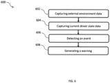
- FIG. 6 illustrates a method 600 for providing assistance to the driver of the vehicle 102, in accordance to an embodiment of the present invention.
- the method can be implemented in any suitable hardware, software, firmware, or combination thereof.
- the method may be considered to be implemented in the above described system and/or the apparatus and/or any electronic device (not shown).
- external environment data and driving pattern data are captured.
- the exterior monitoring module 202 may capture the external environment data and the driving pattern data.
- stereo camera 202A and the long-range narrow filed camera 202B have different capturing ranges in order to capture maximum possible area ahead of the vehicle 102.
- the driver state data is captured.
- the driver monitoring module 206 of the ADAS 106 captures the driver state data.
- an event is detected based on the external environment data, the driver state data, and the driving pattern data.
- the processor 208 may detect the event.
- the external environment data is processed and analyzed to identify any event that may pose a threat from the exterior of the vehicle 102.
- the processor 208 may identify the external environment for stationary and mobile objects, the road edges, lane markings, vehicles in front, pedestrians, street lights, speed signs, or crossroads etc.
- the processor 208 may utilize pixel mapping techniques wherein various images are taken at subsequent time frames detect the event. Pixel maps are generated for these images and compared in real-time to capture any variation or aberrations. For example, for a vehicle moving in-front, various images or video may be taken by the exterior monitoring module 202. Images may be taken at subsequent time intervals, whereas video may be taken continuously. However, if the pixel map determines size increasing in subsequent time frame images or video frames, then the vehicle in-front may be slowing down and is an event that the driver should attend to. Similarly, the processor 208 may use a pixel mapping technique to identify the facial expression and related driver emotions. Also, the determination engine 404 may utilize pre-stored templates to which pixel maps of the driver data may be utilized to determine driver state. Event determined may be based on either the external event, or driver state or a combination of both.
- a warning may be generated.
- the warning generation module 212 may generate the warning.
- the warning generation module 212 may include an audio interface. Therefore, the warning generated may be an audio alarm. This warning may be varied based on the rating values ascertained for the events and the data accompanying the event. Also, the warning may be varied based on driving pattern determined from the external environment data.
- the above described method enables varying of intensity of warning based on the event determined.
- the event determination is based on the external environment data and the driver state data.
- the variation of warning is based on the severity of the event based on the data.
- FIG. 7 a method 700 for providing assistance to the driver of the vehicle 102, in accordance to an embodiment of the present invention.
- an event is detected.
- the event may be for instance, closeness of an object to the vehicle, number of objects on the road, terrain, speed of the vehicle 102.
- the processor 208 may detect the event based on the external environment data received from the exterior monitoring module 202.
- driver state data is received.
- the driver state data may be received from the driver monitoring module 206.
- driving pattern data may be received at step 706.
- the processor 208 may receive the driving pattern data from the exterior monitoring module 202.
- the received driver state information and the driving pattern information is compared.
- the comparison may be made with an existing table of values containing pre-fed values.
- the intensity of the warning may be determined from a table (Table-I described earlier) that stores various combinations of the driver state data, the driving pattern data and the criticality of the event data and a corresponding intensity of warning for each combination. Based on the pre-fed values, the intensity of the warning is determined.
- a warning of the intensity level determined at previous step us generated. Further, the warning generation module 212, then generates the warning of the desired intensity.
- the intensity of the warning may be varied. The warning may be varied based on the rating values ascertained for the events and the data accompanying the event. Also, the warning may be varied based on driving pattern determined from the external environment data.
- the vehicle may take an auto corrective action in case there is no response or acknowledgement from the driver of the vehicle.
- the auto corrective action may be based on a distance threshold that is if for a particular distance from the event, the driver takes no corrective action, the ADAS 106 may take an action automatically.
- the auto corrective action may be a braking action, lane change, sounding horn, etc. For instance, if the vehicle is approaching a pedestrian and the driver of the vehicle has not performed any action when the vehicle is 5 meters away from the pedestrian, then a braking action to stop the vehicle may be performed.
- the processor may send signals to the actuators coupled to the brakes and upon receiving the signal, the actuators may aid in braking.
- the computer system 800 may comprise a central processing unit (“CPU” or "processor”) 802.
- the processing unit 802 may comprise at least one data processor for executing program components for executing user- or system-generated requests.
- the processing unit 802 may include specialized processing units such as integrated system (bus) controllers, memory management control units, floating point units, graphics processing units, digital signal processing units, etc.
- the processing unit 802 may be implemented using mainframe, distributed processor, multi-core, parallel, grid, or other architectures. Some embodiments may utilize embedded technologies like application-specific integrated circuits (ASICs), digital signal processors (DSPs), Field Programmable Gate Arrays (FPGAs), etc.
- ASICs application-specific integrated circuits
- DSPs digital signal processors
- FPGAs Field Programmable Gate Arrays
- the processing unit 802 may be disposed in communication with a communication network 804 via a network interface (not shown in figure).
- the network interface may communicate with the communication network 804.
- the network interface may employ connection protocols including, without limitation, direct connect, Ethernet (e.g., twisted pair 10/100/1000 Base T), transmission control protocol/internet protocol (TCP/IP), token ring, IEEE 802.11a/b/g/n/x, etc.
- the communication network 804 may include, without limitation, a direct interconnection, local area network (LAN), wide area network (WAN), wireless network (e.g., using Wireless Application Protocol) etc.
- the processing unit 802 may be disposed in communication with one or more databases 806 (e.g., a RAM, a ROM, etc.) via the network 804.
- the network 804 may connect to the database 806 including, without limitation, memory drives, removable disc drives, etc., employing connection protocols such as serial advanced technology attachment (SATA), integrated drive electronics (IDE), IEEE-1394, universal serial bus (USB), fiber channel, small computer systems interface (SCSI), etc.
- the memory drives may further include a drum, magnetic disc drive, magneto-optical drive, optical drive, redundant array of independent discs (RAID), solid-state memory devices, solid-state drives, etc.
- the database may include database from the exterior monitoring module 202, the ranging module 204 and the driver monitoring module 206.
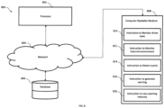
- the processing unit 802 may also be disposed in communication with a computer readable medium 808 (e.g. a compact disk, a USB drive, etc.) via the network 804.
- the network 804 may connect the computer readable medium 808 including without limitation, floppy disks, flexible disks, hard disks, magnetic tape, or any other magnetic storage medium, CD-ROM, DVD, or any other optical medium, a RAM, a PROM, an EPROM, a FLASH-EPROM, or other memory chip or cartridge, or any other tangible medium.
- the computer readable medium 808 may be processed by the computer system 800 or in any other computer system.
- the computer readable medium 808 may include instructions like instruction to monitor driver state, instruction to monitor external environment, instruction to detect events, instruction to generate warnings, or instructions to vary warning intensity.
- the methods illustrated throughout the specification may be implemented in a computer program product that may be executed on a computer.
- the computer program product may comprise a non-transitory computer-readable recording medium on which a control program is recorded, such as a disk, hard drive, or the like.
- a non-transitory computer-readable recording medium such as a disk, hard drive, or the like.
- Common forms of non-transitory computer-readable media include, for example, floppy disks, flexible disks, hard disks, magnetic tape, or any other magnetic storage medium, CD-ROM, DVD, or any other optical medium, a RAM, a PROM, an EPROM, a FLASH-EPROM, or other memory chip or cartridge, or any other tangible medium from which a computer can read and use.
- the method may be implemented in transitory media, such as a transmittable carrier wave in which the control program is embodied as a data signal using transmission media, such as acoustic or light waves, such as those generated during radio wave and infrared data communications, and the like.
- transitory media such as a transmittable carrier wave
- the control program is embodied as a data signal using transmission media, such as acoustic or light waves, such as those generated during radio wave and infrared data communications, and the like.
- the method may be implemented using a combination of a processing unit 802, a non-transitory Computer Readable Medium (CRM) 808, Database 806 all connected to a network 804.
- the computer readable medium may include instructions that may be fetched by the processing unit 802.
- the instructions may include instruction to monitor driver state 810, instruction to monitor external environment 812, instruction to detect events 814, instruction to generate warning 816, and instruction to vary warning intensity 818.
- the processing unit 802 may execute the instruction to monitor driver state 810 to initiate monitoring of the driver state by an exterior monitoring module 202.
- the exterior monitoring module 202 may monitor the driver's facial expressions, reactions, and features to determine if the driver is drowsy, or inattentive, as described earlier.
- the processing unit 802 may also execute the instruction to monitor the external environment 812 to operate an exterior monitoring module, such as the exterior monitoring module 202 as described earlier to record the surrounding of the vehicle and provide the external environment data to the processing unit 802 for processing.
- the processing unit 802 may execute the instruction to detect events 814 to process the inputs received from the exterior monitoring module 202, and the driver monitoring module 202 and detect whether an event has occurred.
- the event may be an approaching vehicle, a pedestrian on a road, or a cyclist close to the vehicle.
- the processing unit 802 may execute the instruction to generate warning 816 to issue a warning to the driver of the vehicle.
- the warning may be issued by a warning generating module, such as the warning generating module 202 of the vehicle 102 as described earlier.
- the processing unit 802 executes the instruction to vary warning intensity 818 to adjust intensity of waring issued to the driver.
- the intensity of the warning may be varied based on various factors such as criticality of the event for instance when the vehicle is very close to the pedestrian, or when the vehicle is close to another vehicle and about to collide. During such critical events, the intensity of the warning is increased.
- the warning issued may be a voice based alert.
- the CRM 808 may include an instruction to prioritize data.
- the processing unit 802 may process the instruction to prioritize data to prioritize data from one of the exterior monitoring module 202 and the driver monitoring module 206 in a case when there is a mismatch between the data of the modules.
- the present invention provides an efficient mechanism of detecting an event and issuing relevant warning to the user with accuracy, wherein the intensity is varied as per the situation. Variation of the intensity helps in providing apt level of warning to the driver of the vehicle that enables the driver to take apt decision about handling the situation and improves driver experience. Further, the present invention detects event in situations when one data set may not be available thereby increasing robustness and reliability of the system and enhancing overall driver safety.
Landscapes
- Engineering & Computer Science (AREA)
- Automation & Control Theory (AREA)
- Human Computer Interaction (AREA)
- Transportation (AREA)
- Mechanical Engineering (AREA)
- Physics & Mathematics (AREA)
- General Physics & Mathematics (AREA)
- Multimedia (AREA)
- Theoretical Computer Science (AREA)
- Traffic Control Systems (AREA)
Claims (12)
- Ein Fahrerassistenzsystem (Advanced Driver Assistance System, ADAS) für ein Fahrzeug, das Folgendes umfasst:ein Fahrerüberwachungsmodul zur Überwachung des Fahrerzustands eines Fahrers im Fahrzeug;ein externes Überwachungsmodul zur Überwachung von mindestens einer externen Umgebung des Fahrzeugs und eines Fahrmusters des Fahrers und zur Anpassung des Sichtbereichs der externen Umgebung, wobei der Interessenbereich auf der Grundlage von Daten angepasst wird, die mit dem Fahrweg des Fahrzeugs verbunden sind, wobei die mit dem Fahrweg verbundenen Daten mindestens einer Indikatorinitiierung, einer Lenkradwinkeländerung, einer vorgefütterten Route,einem Global Positioning System-Eingang entsprechen, und wobei eine Form des Interessenbereichs angepasst wird, um sich an die Änderungen der externen Umgebungsdaten anzupassen, die von dem externen Überwachungsmodul empfangen werden;einen Prozessor, der mit dem Fahrerüberwachungsmodul und dem Außenüberwachungsmodul gekoppelt ist, um
Empfang von Fahrerzustandsdaten aus dem Fahrerüberwachungsmodul und von externen Umgebungsdaten aus dem Außenüberwachungsmodul; und ein Ereignis auf der Grundlage mindestens eines der externen Umgebungsdaten und der Fahrerzustandsdaten zu erkennen; undein mit dem Prozessor gekoppeltes Warnmodul zur Erzeugung einer Warnung für den Fahrer als Reaktion auf das Ereignis, wobei die Intensität der Warnung auf mindestens einem der externen Umgebungsdaten und den Fahrerzustandsdaten beruht. - ADAS nach Anspruch 1, ferner umfassend ein Entfernungsmodul zur Bestimmung eines Abstands
zwischen einem Objekt in der äußeren Umgebung und dem Fahrzeug. - ADAS nach Anspruch 2, wobei das Entfernungsmodul eine Lichtdetektions- und Entfernungseinheit (LiDAR), eine Funkdetektions- und Entfernungseinheit (RADAR), eine Schalldetektions- und Entfernungseinheit (SODAR) und eine Schallnavigations- und Entfernungseinheit (SONAR) ist.
- ADAS nach Anspruch 1, wobei das Außenüberwachungsmodul eine Stereokamera und eine Weitbereichs-Schmalfeldkamera ist.
- Das ADAS nach Anspruch 1 umfasst ferner ein Gewichtungsmodul zur Priorisierung einer Eingabe aus dem Fahrerüberwachungsmodul und das mindestens eine Außenüberwachungsmodul während einer Nichtübereinstimmung zwischen Eingaben aus dem Fahrerüberwachungsmodul und dem Außenüberwachungsmodul.
- ADAS nach Anspruch 1, wobei der Prozessor das Ereignis erkennt durch:Erfassung der externen Umgebung in Datenrahmen, die in nachfolgenden Zeitintervallen erfasst werden, wobei die Zeitintervalle in aufsteigender Reihenfolge sind,Generierung einer Pixelkarte für jeden der erfassten Datenrahmen undVergleich der Pixelkarte eines Datenrahmens, der in einem Zeitintervall erfasst wurde, das früher in aufsteigender Reihenfolge fällt, mit der Pixelkarte eines Datenrahmens, der in einem nachfolgenden Zeitrahmen erfasst wurde, in aufsteigender Reihenfolge.
- ADAS nach Anspruch 1, wobei das zumindest ein Treiberüberwachungsmodul eine ladungsgekoppelte Gerätekamera (CCD) ist.
- ADAS nach Anspruch 7, wobei die CCD-Kamera den Fahrerzustand anhand des Blicks, der Blinzelrate der Augenlider, der Veränderung des Hauttons, der Nasenlöcher, der Kieferbewegungen, des Stirnrunzelns, des Zähneknirschens, der Wangenbewegung, der Lippenbewegung und der Kopfbewegungen überwacht.
- ADAS nach Anspruch 1, wobei jeder Satz des Fahrerzustands und der äußeren Umgebung mit einer Bewertung korreliert sind, wobei jede Bewertung eine entsprechende Intensität der Warnung aufweist.
- Verfahren zur Unterstützung des Fahrers eines Fahrzeugs, das Folgendes umfasst:Erfassung externer Umgebungsdaten im Zusammenhang mit einer externen Umgebung des Fahrzeugs;Erfassung der dem Fahrer zugeordneten Fahrerzustandsdaten;Anpassen einer Region von Interesse einer Ansicht der externen Umgebung auf der Grundlage von Daten, die mit dem Verfahrweg des Fahrzeugs verbunden sind,wobei die mit dem Verfahrweg verbundenen Daten mindestens einer Indikatorinitiierung, einer Änderung des Lenkradwinkels, einer vorgefütterten Route und einer Eingabe für ein globales Positionierungssystem entsprechen,wobei eine Form des interessierenden Bereichs angepasst wird, um sich an Änderungen der externen Umgebungsdaten anzupassen, die vom externen Überwachungsmodul empfangen werden;Verarbeitung der externen Umgebungsdaten und der Fahrerzustandsdaten zur Erkennung eines Ereignisses; undErzeugung einer Warnung für den Fahrer als Reaktion auf das Ereignis, wobei die Intensität der Warnung auf mindestens einer der externen Umgebungsdaten undden Fahrerzustandsdaten basiert.
- Ein nicht-transitorisches computerlesbares Medium (CRM) zur Unterstützung eines Fahrerseines Fahrzeugs, das nicht-transitorische CRM, das Anweisungen umfasst, die von einem Prozessor ausgeführt werden könnenzu:Erfassung externer Umgebungsdaten, die mit einer externen Umgebung des Fahrzeugs verbunden sind;Erfassung des Fahrverhaltens des Fahrers;Erfassung der dem Fahrer zugeordneten Fahrerzustandsdaten;eine Region von Interesse einer Ansicht der externen Umgebung auf der Grundlage von Daten anpassen, die mit dem Verfahrweg des Fahrzeugs verbunden sind, wobei die mit dem Verfahrweg verbundenen Daten mindestens eine einer Indikatorinitiierung, einer Lenkradwinkeländerung, einer vorgefütterten Route undeiner Eingabe für ein globales Positionierungssystem sind, wobei eine Form des interessierenden Bereichs angepasst wird, um sich an Änderungen der externen Umgebungsdaten anzupassen, die vom externen Überwachungsmodul empfangen werden;Verarbeitung der externen Umgebungsdaten, des Fahrmusters und der Fahrerzustandsdaten, um ein Ereignis zu erkennen; undeine Warnung für den Fahrer als Reaktion auf das Ereignis erzeugen, wobei die Intensität der Warnung auf mindestens einem der externen Umgebungsdaten undden Fahrerzustandsdaten basiert.
- Nicht-transitorisches CRM nach Anspruch 13, wobei das CRM ferner eine Anweisung zur Priorisierung von Daten von mindestens einem Fahrerüberwachungsmodul und mindestens einem Außenüberwachungsmodul umfasst.
Applications Claiming Priority (1)
| Application Number | Priority Date | Filing Date | Title |
|---|---|---|---|
| IN201711032922 | 2017-09-18 |
Publications (2)
| Publication Number | Publication Date |
|---|---|
| EP3456599A1 EP3456599A1 (de) | 2019-03-20 |
| EP3456599B1 true EP3456599B1 (de) | 2025-01-22 |
Family
ID=60953595
Family Applications (1)
| Application Number | Title | Priority Date | Filing Date |
|---|---|---|---|
| EP17210132.1A Active EP3456599B1 (de) | 2017-09-18 | 2017-12-22 | Überwachung von fahrern und der äusseren umgebung für fahrzeuge |
Country Status (2)
| Country | Link |
|---|---|
| US (1) | US10861336B2 (de) |
| EP (1) | EP3456599B1 (de) |
Families Citing this family (9)
| Publication number | Priority date | Publication date | Assignee | Title |
|---|---|---|---|---|
| KR102634349B1 (ko) * | 2018-10-11 | 2024-02-07 | 현대자동차주식회사 | 차량의 제어 장치 및 방법 |
| KR20200128474A (ko) * | 2019-04-24 | 2020-11-13 | 현대자동차주식회사 | 차량용 수동 주행 전환 알림 장치 및 그의 수동 주행 전환 알림 방법과 그를 포함하는 차량 |
| CN110705502B (zh) * | 2019-10-14 | 2023-07-28 | 首约科技(北京)有限公司 | 一种驾驶员监控设备优化方法 |
| CN113370990B (zh) * | 2020-03-10 | 2025-11-07 | 深圳引望智能技术有限公司 | 驾驶辅助方法和驾驶辅助装置 |
| CN112141119B (zh) * | 2020-09-23 | 2022-03-11 | 上海商汤临港智能科技有限公司 | 智能驾驶控制方法及装置、车辆、电子设备和存储介质 |
| CN112693453B (zh) * | 2021-01-04 | 2022-07-01 | 广州小鹏自动驾驶科技有限公司 | 一种车辆避让方法和装置 |
| FR3128433A1 (fr) * | 2021-10-21 | 2023-04-28 | Psa Automobiles Sa | Procédé et système pour fournir au moins une indication visant à alerter dans l’habitacle d’un véhicule automobile de l’existence d’un danger |
| CN115675504A (zh) * | 2022-10-31 | 2023-02-03 | 华为技术有限公司 | 一种车辆告警方法以及相关设备 |
| CN120096585B (zh) * | 2025-04-17 | 2026-01-02 | 奇瑞汽车股份有限公司 | 基于多数据融合感知的安全识别车辆控制方法及系统 |
Citations (2)
| Publication number | Priority date | Publication date | Assignee | Title |
|---|---|---|---|---|
| DE102016100729A1 (de) * | 2015-01-29 | 2016-08-04 | Toyota Motor Engineering & Manufacturing North America Inc. | Betrieb eines autonomen Fahrzeugs in Umgebungen mit blockierter Sicht |
| US20160332569A1 (en) * | 2015-05-15 | 2016-11-17 | Honda Motor Co., Ltd. | Determining a driver alert level for a vehicle alert system and method of use |
Family Cites Families (11)
| Publication number | Priority date | Publication date | Assignee | Title |
|---|---|---|---|---|
| DE4111993B4 (de) * | 1990-04-23 | 2005-05-25 | Volkswagen Ag | Kamera für ein Bildverarbeitungssystem |
| US8487929B2 (en) * | 2009-09-09 | 2013-07-16 | Advanced Micro Devices, Inc. | Resolution enhancement of video stream based on spatial and temporal correlation |
| US9122933B2 (en) * | 2013-03-13 | 2015-09-01 | Mighty Carma, Inc. | After market driving assistance system |
| EP2892020A1 (de) * | 2014-01-06 | 2015-07-08 | Harman International Industries, Incorporated | Kontinuierliche Identitätsüberwachung zur Klassifizierung von Fahrinformationen zur Fahrleistungsanalyse |
| GB2528084B (en) * | 2014-07-08 | 2018-05-09 | Jaguar Land Rover Ltd | Notification system and method |
| KR101555444B1 (ko) * | 2014-07-10 | 2015-10-06 | 현대모비스 주식회사 | 차량탑재 상황감지 장치 및 그 방법 |
| US9592828B2 (en) * | 2015-04-13 | 2017-03-14 | Nec Corporation | Long term driving danger prediction system |
| US9493118B1 (en) * | 2015-06-24 | 2016-11-15 | Delphi Technologies, Inc. | Cognitive driver assist with variable warning for automated vehicles |
| US20180046869A1 (en) * | 2016-08-10 | 2018-02-15 | Surround.IO Corporation | Method and Apparatus for Providing Information Via Collected and Stored Metadata Using Inferred Attentional Model |
| US11067996B2 (en) * | 2016-09-08 | 2021-07-20 | Siemens Industry Software Inc. | Event-driven region of interest management |
| US10837790B2 (en) * | 2017-08-01 | 2020-11-17 | Nio Usa, Inc. | Productive and accident-free driving modes for a vehicle |
-
2017
- 2017-12-22 EP EP17210132.1A patent/EP3456599B1/de active Active
-
2018
- 2018-09-15 US US16/132,371 patent/US10861336B2/en active Active
Patent Citations (2)
| Publication number | Priority date | Publication date | Assignee | Title |
|---|---|---|---|---|
| DE102016100729A1 (de) * | 2015-01-29 | 2016-08-04 | Toyota Motor Engineering & Manufacturing North America Inc. | Betrieb eines autonomen Fahrzeugs in Umgebungen mit blockierter Sicht |
| US20160332569A1 (en) * | 2015-05-15 | 2016-11-17 | Honda Motor Co., Ltd. | Determining a driver alert level for a vehicle alert system and method of use |
Also Published As
| Publication number | Publication date |
|---|---|
| US20190088130A1 (en) | 2019-03-21 |
| EP3456599A1 (de) | 2019-03-20 |
| US10861336B2 (en) | 2020-12-08 |
Similar Documents
| Publication | Publication Date | Title |
|---|---|---|
| EP3456599B1 (de) | Überwachung von fahrern und der äusseren umgebung für fahrzeuge | |
| JP7650964B2 (ja) | インテリジェントドライブ制御方法及び装置、車両、電子機器並びに記憶媒体 | |
| JP7397807B2 (ja) | ライダー支援システム及び方法 | |
| US10745030B2 (en) | Providing location and driving behavior based alerts | |
| EP3564086B1 (de) | Verwaltung der fahrmodi eines fahrzeugs | |
| TWI653170B (zh) | 駕駛提示方法與系統 | |
| JP2024546060A (ja) | 指数的リスクを融合した状況評価(safer)に基づいて車両の運転を支援する装置および方法 | |
| US11745745B2 (en) | Systems and methods for improving driver attention awareness | |
| JP2004362586A (ja) | 車両用画像処理システム | |
| TW202443509A (zh) | 用於警示駕駛員的警示模態選擇 | |
| CN119037415B (zh) | 多模态大模型驾驶风险判断方法、系统、介质及程序产品 | |
| US12027050B2 (en) | Hazard notification method and system for implementing | |
| WO2018168097A1 (ja) | 運転状態判定装置、運転状態判定方法及び運転状態判定のためのプログラム | |
| EP3566921B1 (de) | Bereitstellung relevanter alarme an einen fahrer eines fahrzeugs | |
| JP7639889B2 (ja) | 画像解析装置、画像解析方法及びプログラム | |
| JP2018097479A (ja) | 運転支援装置、運転支援方法、運転支援プログラム、及び運転支援システム | |
| CN109823344B (zh) | 驾驶提示方法与系统 | |
| CN114715143A (zh) | 车辆控制方法、装置、车辆及存储介质 | |
| JP2018097485A (ja) | 運転支援装置、運転支援方法、運転支援プログラム、及び運転支援システム | |
| EP4406797B1 (de) | Kollisionswarnsystem für ein fahrzeug | |
| US20260028024A1 (en) | Driver assistance control device, driver assistance method, and nontransitory computer storage medium | |
| Harsha | ADAVANCE DRIVER ASSISTENCE SYSTEM (ADAS) | |
| JP2025078380A (ja) | 運転支援制御装置、運転支援方法、及び車両 | |
| JP2025073188A (ja) | 危険運転警告装置、車両、および、危険運転警告方法 | |
| KR20260057743A (ko) | 자동차 사각지대를 모니터링하기 위한 차량 안전 사각 시스템 및 방법 |
Legal Events
| Date | Code | Title | Description |
|---|---|---|---|
| PUAI | Public reference made under article 153(3) epc to a published international application that has entered the european phase |
Free format text: ORIGINAL CODE: 0009012 |
|
| STAA | Information on the status of an ep patent application or granted ep patent |
Free format text: STATUS: THE APPLICATION HAS BEEN PUBLISHED |
|
| AK | Designated contracting states |
Kind code of ref document: A1 Designated state(s): AL AT BE BG CH CY CZ DE DK EE ES FI FR GB GR HR HU IE IS IT LI LT LU LV MC MK MT NL NO PL PT RO RS SE SI SK SM TR |
|
| AX | Request for extension of the european patent |
Extension state: BA ME |
|
| STAA | Information on the status of an ep patent application or granted ep patent |
Free format text: STATUS: REQUEST FOR EXAMINATION WAS MADE |
|
| 17P | Request for examination filed |
Effective date: 20190920 |
|
| RBV | Designated contracting states (corrected) |
Designated state(s): AL AT BE BG CH CY CZ DE DK EE ES FI FR GB GR HR HU IE IS IT LI LT LU LV MC MK MT NL NO PL PT RO RS SE SI SK SM TR |
|
| STAA | Information on the status of an ep patent application or granted ep patent |
Free format text: STATUS: EXAMINATION IS IN PROGRESS |
|
| 17Q | First examination report despatched |
Effective date: 20220511 |
|
| RAP1 | Party data changed (applicant data changed or rights of an application transferred) |
Owner name: NOVUS HI-TECH ROBOTIC SYSTEMZ PRIVATE LTD. |
|
| GRAP | Despatch of communication of intention to grant a patent |
Free format text: ORIGINAL CODE: EPIDOSNIGR1 |
|
| STAA | Information on the status of an ep patent application or granted ep patent |
Free format text: STATUS: GRANT OF PATENT IS INTENDED |
|
| RIC1 | Information provided on ipc code assigned before grant |
Ipc: B60W 50/00 20060101ALN20240718BHEP Ipc: B60W 50/16 20120101ALI20240718BHEP Ipc: B60W 50/14 20120101AFI20240718BHEP |
|
| RIC1 | Information provided on ipc code assigned before grant |
Ipc: B60W 50/00 20060101ALN20240724BHEP Ipc: B60W 50/16 20120101ALI20240724BHEP Ipc: B60W 50/14 20120101AFI20240724BHEP |
|
| INTG | Intention to grant announced |
Effective date: 20240805 |
|
| GRAS | Grant fee paid |
Free format text: ORIGINAL CODE: EPIDOSNIGR3 |
|
| GRAA | (expected) grant |
Free format text: ORIGINAL CODE: 0009210 |
|
| STAA | Information on the status of an ep patent application or granted ep patent |
Free format text: STATUS: THE PATENT HAS BEEN GRANTED |
|
| AK | Designated contracting states |
Kind code of ref document: B1 Designated state(s): AL AT BE BG CH CY CZ DE DK EE ES FI FR GB GR HR HU IE IS IT LI LT LU LV MC MK MT NL NO PL PT RO RS SE SI SK SM TR |
|
| REG | Reference to a national code |
Ref country code: GB Ref legal event code: FG4D |
|
| REG | Reference to a national code |
Ref country code: CH Ref legal event code: EP |
|
| REG | Reference to a national code |
Ref country code: IE Ref legal event code: FG4D |
|
| REG | Reference to a national code |
Ref country code: DE Ref legal event code: R096 Ref document number: 602017087416 Country of ref document: DE |
|
| REG | Reference to a national code |
Ref country code: NL Ref legal event code: MP Effective date: 20250122 |
|
| PG25 | Lapsed in a contracting state [announced via postgrant information from national office to epo] |
Ref country code: NL Free format text: LAPSE BECAUSE OF FAILURE TO SUBMIT A TRANSLATION OF THE DESCRIPTION OR TO PAY THE FEE WITHIN THE PRESCRIBED TIME-LIMIT Effective date: 20250122 |
|
| PG25 | Lapsed in a contracting state [announced via postgrant information from national office to epo] |
Ref country code: RS Free format text: LAPSE BECAUSE OF FAILURE TO SUBMIT A TRANSLATION OF THE DESCRIPTION OR TO PAY THE FEE WITHIN THE PRESCRIBED TIME-LIMIT Effective date: 20250422 |
|
| PG25 | Lapsed in a contracting state [announced via postgrant information from national office to epo] |
Ref country code: FI Free format text: LAPSE BECAUSE OF FAILURE TO SUBMIT A TRANSLATION OF THE DESCRIPTION OR TO PAY THE FEE WITHIN THE PRESCRIBED TIME-LIMIT Effective date: 20250122 |
|
| PG25 | Lapsed in a contracting state [announced via postgrant information from national office to epo] |
Ref country code: PL Free format text: LAPSE BECAUSE OF FAILURE TO SUBMIT A TRANSLATION OF THE DESCRIPTION OR TO PAY THE FEE WITHIN THE PRESCRIBED TIME-LIMIT Effective date: 20250122 |
|
| PG25 | Lapsed in a contracting state [announced via postgrant information from national office to epo] |
Ref country code: ES Free format text: LAPSE BECAUSE OF FAILURE TO SUBMIT A TRANSLATION OF THE DESCRIPTION OR TO PAY THE FEE WITHIN THE PRESCRIBED TIME-LIMIT Effective date: 20250122 |
|
| REG | Reference to a national code |
Ref country code: LT Ref legal event code: MG9D |
|
| PG25 | Lapsed in a contracting state [announced via postgrant information from national office to epo] |
Ref country code: NO Free format text: LAPSE BECAUSE OF FAILURE TO SUBMIT A TRANSLATION OF THE DESCRIPTION OR TO PAY THE FEE WITHIN THE PRESCRIBED TIME-LIMIT Effective date: 20250422 Ref country code: IS Free format text: LAPSE BECAUSE OF FAILURE TO SUBMIT A TRANSLATION OF THE DESCRIPTION OR TO PAY THE FEE WITHIN THE PRESCRIBED TIME-LIMIT Effective date: 20250522 |
|
| REG | Reference to a national code |
Ref country code: AT Ref legal event code: MK05 Ref document number: 1761271 Country of ref document: AT Kind code of ref document: T Effective date: 20250122 |
|
| PG25 | Lapsed in a contracting state [announced via postgrant information from national office to epo] |
Ref country code: HR Free format text: LAPSE BECAUSE OF FAILURE TO SUBMIT A TRANSLATION OF THE DESCRIPTION OR TO PAY THE FEE WITHIN THE PRESCRIBED TIME-LIMIT Effective date: 20250122 |
|
| PG25 | Lapsed in a contracting state [announced via postgrant information from national office to epo] |
Ref country code: PT Free format text: LAPSE BECAUSE OF FAILURE TO SUBMIT A TRANSLATION OF THE DESCRIPTION OR TO PAY THE FEE WITHIN THE PRESCRIBED TIME-LIMIT Effective date: 20250522 Ref country code: LV Free format text: LAPSE BECAUSE OF FAILURE TO SUBMIT A TRANSLATION OF THE DESCRIPTION OR TO PAY THE FEE WITHIN THE PRESCRIBED TIME-LIMIT Effective date: 20250122 |
|
| PG25 | Lapsed in a contracting state [announced via postgrant information from national office to epo] |
Ref country code: GR Free format text: LAPSE BECAUSE OF FAILURE TO SUBMIT A TRANSLATION OF THE DESCRIPTION OR TO PAY THE FEE WITHIN THE PRESCRIBED TIME-LIMIT Effective date: 20250423 Ref country code: BG Free format text: LAPSE BECAUSE OF FAILURE TO SUBMIT A TRANSLATION OF THE DESCRIPTION OR TO PAY THE FEE WITHIN THE PRESCRIBED TIME-LIMIT Effective date: 20250122 |
|
| PG25 | Lapsed in a contracting state [announced via postgrant information from national office to epo] |
Ref country code: AT Free format text: LAPSE BECAUSE OF FAILURE TO SUBMIT A TRANSLATION OF THE DESCRIPTION OR TO PAY THE FEE WITHIN THE PRESCRIBED TIME-LIMIT Effective date: 20250122 |
|
| PG25 | Lapsed in a contracting state [announced via postgrant information from national office to epo] |
Ref country code: SE Free format text: LAPSE BECAUSE OF FAILURE TO SUBMIT A TRANSLATION OF THE DESCRIPTION OR TO PAY THE FEE WITHIN THE PRESCRIBED TIME-LIMIT Effective date: 20250122 |
|
| PG25 | Lapsed in a contracting state [announced via postgrant information from national office to epo] |
Ref country code: SM Free format text: LAPSE BECAUSE OF FAILURE TO SUBMIT A TRANSLATION OF THE DESCRIPTION OR TO PAY THE FEE WITHIN THE PRESCRIBED TIME-LIMIT Effective date: 20250122 |
|
| PG25 | Lapsed in a contracting state [announced via postgrant information from national office to epo] |
Ref country code: DK Free format text: LAPSE BECAUSE OF FAILURE TO SUBMIT A TRANSLATION OF THE DESCRIPTION OR TO PAY THE FEE WITHIN THE PRESCRIBED TIME-LIMIT Effective date: 20250122 |
|
| PG25 | Lapsed in a contracting state [announced via postgrant information from national office to epo] |
Ref country code: IT Free format text: LAPSE BECAUSE OF FAILURE TO SUBMIT A TRANSLATION OF THE DESCRIPTION OR TO PAY THE FEE WITHIN THE PRESCRIBED TIME-LIMIT Effective date: 20250122 |
|
| PG25 | Lapsed in a contracting state [announced via postgrant information from national office to epo] |
Ref country code: EE Free format text: LAPSE BECAUSE OF FAILURE TO SUBMIT A TRANSLATION OF THE DESCRIPTION OR TO PAY THE FEE WITHIN THE PRESCRIBED TIME-LIMIT Effective date: 20250122 Ref country code: CZ Free format text: LAPSE BECAUSE OF FAILURE TO SUBMIT A TRANSLATION OF THE DESCRIPTION OR TO PAY THE FEE WITHIN THE PRESCRIBED TIME-LIMIT Effective date: 20250122 |
|
| REG | Reference to a national code |
Ref country code: DE Ref legal event code: R097 Ref document number: 602017087416 Country of ref document: DE |
|
| PG25 | Lapsed in a contracting state [announced via postgrant information from national office to epo] |
Ref country code: RO Free format text: LAPSE BECAUSE OF FAILURE TO SUBMIT A TRANSLATION OF THE DESCRIPTION OR TO PAY THE FEE WITHIN THE PRESCRIBED TIME-LIMIT Effective date: 20250122 |
|
| PG25 | Lapsed in a contracting state [announced via postgrant information from national office to epo] |
Ref country code: SK Free format text: LAPSE BECAUSE OF FAILURE TO SUBMIT A TRANSLATION OF THE DESCRIPTION OR TO PAY THE FEE WITHIN THE PRESCRIBED TIME-LIMIT Effective date: 20250122 |
|
| PLBE | No opposition filed within time limit |
Free format text: ORIGINAL CODE: 0009261 |
|
| STAA | Information on the status of an ep patent application or granted ep patent |
Free format text: STATUS: NO OPPOSITION FILED WITHIN TIME LIMIT |
|
| 26N | No opposition filed |
Effective date: 20251023 |
|
| PGFP | Annual fee paid to national office [announced via postgrant information from national office to epo] |
Ref country code: DE Payment date: 20251210 Year of fee payment: 9 |
|
| PGFP | Annual fee paid to national office [announced via postgrant information from national office to epo] |
Ref country code: GB Payment date: 20251117 Year of fee payment: 9 |