EP3456594A2 - Smart brake system for safety when moving on slope - Google Patents
Smart brake system for safety when moving on slope Download PDFInfo
- Publication number
- EP3456594A2 EP3456594A2 EP16901792.8A EP16901792A EP3456594A2 EP 3456594 A2 EP3456594 A2 EP 3456594A2 EP 16901792 A EP16901792 A EP 16901792A EP 3456594 A2 EP3456594 A2 EP 3456594A2
- Authority
- EP
- European Patent Office
- Prior art keywords
- brake
- ratchet
- deceleration
- slope
- fluid
- Prior art date
- Legal status (The legal status is an assumption and is not a legal conclusion. Google has not performed a legal analysis and makes no representation as to the accuracy of the status listed.)
- Withdrawn
Links
Images



Classifications
-
- A—HUMAN NECESSITIES
- A61—MEDICAL OR VETERINARY SCIENCE; HYGIENE
- A61G—TRANSPORT, PERSONAL CONVEYANCES, OR ACCOMMODATION SPECIALLY ADAPTED FOR PATIENTS OR DISABLED PERSONS; OPERATING TABLES OR CHAIRS; CHAIRS FOR DENTISTRY; FUNERAL DEVICES
- A61G5/00—Chairs or personal conveyances specially adapted for patients or disabled persons, e.g. wheelchairs
- A61G5/10—Parts, details or accessories
- A61G5/1005—Wheelchairs having brakes
- A61G5/1021—Wheelchairs having brakes engaging specific brake elements
-
- B—PERFORMING OPERATIONS; TRANSPORTING
- B60—VEHICLES IN GENERAL
- B60T—VEHICLE BRAKE CONTROL SYSTEMS OR PARTS THEREOF; BRAKE CONTROL SYSTEMS OR PARTS THEREOF, IN GENERAL; ARRANGEMENT OF BRAKING ELEMENTS ON VEHICLES IN GENERAL; PORTABLE DEVICES FOR PREVENTING UNWANTED MOVEMENT OF VEHICLES; VEHICLE MODIFICATIONS TO FACILITATE COOLING OF BRAKES
- B60T7/00—Brake-action initiating means
- B60T7/12—Brake-action initiating means for automatic initiation; for initiation not subject to will of driver or passenger
- B60T7/122—Brake-action initiating means for automatic initiation; for initiation not subject to will of driver or passenger for locking of reverse movement
-
- A—HUMAN NECESSITIES
- A61—MEDICAL OR VETERINARY SCIENCE; HYGIENE
- A61G—TRANSPORT, PERSONAL CONVEYANCES, OR ACCOMMODATION SPECIALLY ADAPTED FOR PATIENTS OR DISABLED PERSONS; OPERATING TABLES OR CHAIRS; CHAIRS FOR DENTISTRY; FUNERAL DEVICES
- A61G5/00—Chairs or personal conveyances specially adapted for patients or disabled persons, e.g. wheelchairs
- A61G5/04—Chairs or personal conveyances specially adapted for patients or disabled persons, e.g. wheelchairs motor-driven
-
- A—HUMAN NECESSITIES
- A61—MEDICAL OR VETERINARY SCIENCE; HYGIENE
- A61G—TRANSPORT, PERSONAL CONVEYANCES, OR ACCOMMODATION SPECIALLY ADAPTED FOR PATIENTS OR DISABLED PERSONS; OPERATING TABLES OR CHAIRS; CHAIRS FOR DENTISTRY; FUNERAL DEVICES
- A61G5/00—Chairs or personal conveyances specially adapted for patients or disabled persons, e.g. wheelchairs
- A61G5/10—Parts, details or accessories
-
- A—HUMAN NECESSITIES
- A61—MEDICAL OR VETERINARY SCIENCE; HYGIENE
- A61G—TRANSPORT, PERSONAL CONVEYANCES, OR ACCOMMODATION SPECIALLY ADAPTED FOR PATIENTS OR DISABLED PERSONS; OPERATING TABLES OR CHAIRS; CHAIRS FOR DENTISTRY; FUNERAL DEVICES
- A61G5/00—Chairs or personal conveyances specially adapted for patients or disabled persons, e.g. wheelchairs
- A61G5/10—Parts, details or accessories
- A61G5/1005—Wheelchairs having brakes
- A61G5/1021—Wheelchairs having brakes engaging specific brake elements
- A61G5/1027—Hub elements, e.g. drums
-
- B—PERFORMING OPERATIONS; TRANSPORTING
- B60—VEHICLES IN GENERAL
- B60T—VEHICLE BRAKE CONTROL SYSTEMS OR PARTS THEREOF; BRAKE CONTROL SYSTEMS OR PARTS THEREOF, IN GENERAL; ARRANGEMENT OF BRAKING ELEMENTS ON VEHICLES IN GENERAL; PORTABLE DEVICES FOR PREVENTING UNWANTED MOVEMENT OF VEHICLES; VEHICLE MODIFICATIONS TO FACILITATE COOLING OF BRAKES
- B60T7/00—Brake-action initiating means
- B60T7/12—Brake-action initiating means for automatic initiation; for initiation not subject to will of driver or passenger
-
- B—PERFORMING OPERATIONS; TRANSPORTING
- B60—VEHICLES IN GENERAL
- B60T—VEHICLE BRAKE CONTROL SYSTEMS OR PARTS THEREOF; BRAKE CONTROL SYSTEMS OR PARTS THEREOF, IN GENERAL; ARRANGEMENT OF BRAKING ELEMENTS ON VEHICLES IN GENERAL; PORTABLE DEVICES FOR PREVENTING UNWANTED MOVEMENT OF VEHICLES; VEHICLE MODIFICATIONS TO FACILITATE COOLING OF BRAKES
- B60T8/00—Arrangements for adjusting wheel-braking force to meet varying vehicular or ground-surface conditions, e.g. limiting or varying distribution of braking force
- B60T8/24—Arrangements for adjusting wheel-braking force to meet varying vehicular or ground-surface conditions, e.g. limiting or varying distribution of braking force responsive to vehicle inclination or change of direction, e.g. negotiating bends
-
- B—PERFORMING OPERATIONS; TRANSPORTING
- B60—VEHICLES IN GENERAL
- B60T—VEHICLE BRAKE CONTROL SYSTEMS OR PARTS THEREOF; BRAKE CONTROL SYSTEMS OR PARTS THEREOF, IN GENERAL; ARRANGEMENT OF BRAKING ELEMENTS ON VEHICLES IN GENERAL; PORTABLE DEVICES FOR PREVENTING UNWANTED MOVEMENT OF VEHICLES; VEHICLE MODIFICATIONS TO FACILITATE COOLING OF BRAKES
- B60T8/00—Arrangements for adjusting wheel-braking force to meet varying vehicular or ground-surface conditions, e.g. limiting or varying distribution of braking force
- B60T8/24—Arrangements for adjusting wheel-braking force to meet varying vehicular or ground-surface conditions, e.g. limiting or varying distribution of braking force responsive to vehicle inclination or change of direction, e.g. negotiating bends
- B60T8/245—Longitudinal vehicle inclination
-
- F—MECHANICAL ENGINEERING; LIGHTING; HEATING; WEAPONS; BLASTING
- F16—ENGINEERING ELEMENTS AND UNITS; GENERAL MEASURES FOR PRODUCING AND MAINTAINING EFFECTIVE FUNCTIONING OF MACHINES OR INSTALLATIONS; THERMAL INSULATION IN GENERAL
- F16D—COUPLINGS FOR TRANSMITTING ROTATION; CLUTCHES; BRAKES
- F16D59/00—Self-acting brakes, e.g. coming into operation at a predetermined speed
-
- F—MECHANICAL ENGINEERING; LIGHTING; HEATING; WEAPONS; BLASTING
- F16—ENGINEERING ELEMENTS AND UNITS; GENERAL MEASURES FOR PRODUCING AND MAINTAINING EFFECTIVE FUNCTIONING OF MACHINES OR INSTALLATIONS; THERMAL INSULATION IN GENERAL
- F16D—COUPLINGS FOR TRANSMITTING ROTATION; CLUTCHES; BRAKES
- F16D65/00—Parts or details
- F16D65/14—Actuating mechanisms for brakes; Means for initiating operation at a predetermined position
-
- F—MECHANICAL ENGINEERING; LIGHTING; HEATING; WEAPONS; BLASTING
- F16—ENGINEERING ELEMENTS AND UNITS; GENERAL MEASURES FOR PRODUCING AND MAINTAINING EFFECTIVE FUNCTIONING OF MACHINES OR INSTALLATIONS; THERMAL INSULATION IN GENERAL
- F16H—GEARING
- F16H1/00—Toothed gearings for conveying rotary motion
- F16H1/02—Toothed gearings for conveying rotary motion without gears having orbital motion
- F16H1/04—Toothed gearings for conveying rotary motion without gears having orbital motion involving only two intermeshing members
- F16H1/06—Toothed gearings for conveying rotary motion without gears having orbital motion involving only two intermeshing members with parallel axes
- F16H1/10—Toothed gearings for conveying rotary motion without gears having orbital motion involving only two intermeshing members with parallel axes one of the members being internally toothed
-
- B—PERFORMING OPERATIONS; TRANSPORTING
- B60—VEHICLES IN GENERAL
- B60T—VEHICLE BRAKE CONTROL SYSTEMS OR PARTS THEREOF; BRAKE CONTROL SYSTEMS OR PARTS THEREOF, IN GENERAL; ARRANGEMENT OF BRAKING ELEMENTS ON VEHICLES IN GENERAL; PORTABLE DEVICES FOR PREVENTING UNWANTED MOVEMENT OF VEHICLES; VEHICLE MODIFICATIONS TO FACILITATE COOLING OF BRAKES
- B60T17/00—Component parts, details, or accessories of power brake systems not covered by groups B60T8/00, B60T13/00 or B60T15/00, or presenting other characteristic features
- B60T17/06—Applications or arrangements of reservoirs
-
- B—PERFORMING OPERATIONS; TRANSPORTING
- B60—VEHICLES IN GENERAL
- B60T—VEHICLE BRAKE CONTROL SYSTEMS OR PARTS THEREOF; BRAKE CONTROL SYSTEMS OR PARTS THEREOF, IN GENERAL; ARRANGEMENT OF BRAKING ELEMENTS ON VEHICLES IN GENERAL; PORTABLE DEVICES FOR PREVENTING UNWANTED MOVEMENT OF VEHICLES; VEHICLE MODIFICATIONS TO FACILITATE COOLING OF BRAKES
- B60T2201/00—Particular use of vehicle brake systems; Special systems using also the brakes; Special software modules within the brake system controller
- B60T2201/04—Hill descent control
-
- F—MECHANICAL ENGINEERING; LIGHTING; HEATING; WEAPONS; BLASTING
- F16—ENGINEERING ELEMENTS AND UNITS; GENERAL MEASURES FOR PRODUCING AND MAINTAINING EFFECTIVE FUNCTIONING OF MACHINES OR INSTALLATIONS; THERMAL INSULATION IN GENERAL
- F16D—COUPLINGS FOR TRANSMITTING ROTATION; CLUTCHES; BRAKES
- F16D2125/00—Components of actuators
- F16D2125/18—Mechanical mechanisms
- F16D2125/20—Mechanical mechanisms converting rotation to linear movement or vice versa
- F16D2125/22—Mechanical mechanisms converting rotation to linear movement or vice versa acting transversely to the axis of rotation
- F16D2125/28—Cams; Levers with cams
Definitions
- the present invention relates to a smart brake system, and more particularly to a brake automatic control system using gravity and buoyancy, which controls a brake to work in a deceleration mode on a descending slope and in a ratchet mode to prevent backward rolling on an ascending slope, thereby making safe movement even on the slopes.
- a wheelchair, a baby carriage, a walker or the like means for transportation with wheels maintains a speed on a flat land but accelerates on a descending slope or rolls backward on an ascending slope, and therefore accidents frequently occur.
- the wheelchair is the transportation means used for a patient who is indisposed, and therefore accidents are highly likely to occur while the wheelchair is moving on an ascending or descending slope since the patient who sits in the wheelchair is unwell. Therefore, the wheelchair requires special attention while moving on the ascending or descending slope.
- the wheelchair accelerates and moves so fast that a person sitting thereon may get injured seriously by falling or secondary collision.
- the wheelchair may roll backward while going up the ascending slope, and thus a person sitting therein may get injured seriously by falling or secondary collision.
- the baby carriage is moving as pushed by a guardian from behind, and has risks of accidents while moving on the slopes like the wheelchair.
- the bicycle for a toddler or child also has risks of accidents on the descending or ascending slope.
- the means for transportation with the wheel has risks of accidents while moving on the slopes.
- an aspect of the present invention is to provide a smart brake system for safety at movement on a slope, in which the brake automatically works based on gravity and buoyancy to prevent accidents while moving on the slope as buoyancy is kept corresponding to change in gravity on a flat land, an ascending slope or a descending slope.
- a smart brake system for safety at movement on a slope including: a multi-brake which includes a deceleration brake for working while moving on a descending slope and a ratchet brake for working while moving on an ascending slope; and a brake controller which selectively controls one of the deceleration brake and the ratchet brake to work as buoyancy of fluid is varied depending on the movement on the descending or the ascending slope.
- the multi-brake includes the deceleration brake configured to decelerate while moving on a descending slope; the ratchet brake formed to be coaxially adjacent to the deceleration brake and preventing backward rolling by ratchet locking while moving on the ascending slope; and a brake drum configured to accommodate both the deceleration brake and the ratchet brake, the brake drum including a ratchet brake accommodating portion formed with a ratchet groove corresponding to a ratchet of the ratchet brake.
- a smart brake control system has a noticeable effect on preventing accidents while moving on a slope such as an ascending or descending slope since one of two different brakes selectively work corresponding to change in gravity on the ascending slope or the descending slope.
- a smart brake system may include a first brake working on a descending slope, a second brake working on an ascending slope, and a brake controller selectively controlling one of the operations of the first and second brakes in accordance with change in gravity.
- the smart brake system may include a multi-brake, which includes a deceleration brake configured to work on the descending slope, a ratchet brake configured to work on the ascending slope, and the brake controller controlling the deceleration or ratchet brake to work as buoyancy changes in a fluid corresponding to the descending or the ascending slope.
- a smart brake system according to the present invention may be applied to a wheelchair, a baby carriage, a walker, a cart, a handcart, a handcar, a rear car, a bicycle, and the like means for transportation with a wheel, in particular any human-powered vehicles.
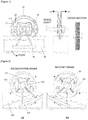
- FIG. 1 schematically illustrates a brake control system provided in a wheel shaft according to an exemplary embodiment of the present invention
- FIG. 2 illustrates that the brake control system of FIG. 1 works on a descending slope and an ascending slope.
- the smart brake system may include a first brake working on a descending slope, a second brake working on an ascending slope, and a brake controller selectively controlling one of the operations of the first and second brakes in accordance with change in gravity.
- the smart brake system may include a multi-brake, which includes a deceleration brake 10 configured to work on the descending slope, a ratchet brake 20 configured to work on the ascending slope, and the brake controller 30 controlling the operation of the deceleration or ratchet brake as gravity or buoyancy changes in a fluid corresponding to the descending or the ascending slope.
- the multi-brake includes the deceleration brake 10 and the ratchet brake 20, which are coaxially arranged in parallel with each other, and a brake drum 50 in which both the deceleration brake 10 and the ratchet brake 20 are accommodated.
- a portion for accommodating the ratchet brake 20 is formed with a ratchet groove corresponding to a ratchet of the ratchet brake 20.
- the ratchet and the ratchet groove may be formed to have directionality for support only unidirectional movement. When the ratchet is locked to the ratchet groove, only forward movement is allowed and backward rolling is prevented.
- the deceleration brake works, the deceleration brake is in contact with the inner surface of the drum, thereby decreasing speed.
- the ratchet brake works, the ratchet is contact with the ratchet groove formed inside the drum and thus the movement is stopped without the backward rolling, thereby maintaining a current position allowing the forward movement.
- deceleration brake 10 and the ratchet brake 20 may form a pair to face each other.
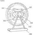
- the brake controller 30 may include a fluid tank filled with fluid; a rotary shaft 310 rotatably coupled to a wheel shaft; a pair of first springs 321 and 322 respectively connected to the rotary shaft 310 and the pair of deceleration brakes 10; and a pair of second springs 331 and 332 respectively connected to the rotary shaft 310 and the pair of ratchet brakes 20; and a pendulum weight 340 coupled to the rotary shaft 310, soaked in the fluid of the fluid tank, and swing left and right according to changes in the gravity of the fluid.
- the rotary shaft 310 has an elliptical shape, and one pair of first springs 321 and 322 and one pair of second springs 331 and 332 are coupled to the rotary shaft 310 and approximately perpendicular to each other. As the rotary shaft 310 rotates, only one brake of the multi-brakes selectively receives force and works in such a manner that force is transmitted to only the pair of first springs 321 and 322 when the pendulum weight 340 moves forward and force is transmitted to only the pair of second springs 331 and 332 when the pendulum weight 340 moves backward.
- the pendulum weigh 340 is arranged to float in the fluid of the fluid tank by buoyancy. When the wheel is moving on the flat land, the pendulum weight 340 is always positioned in the middle and thus no brakes work.
- the gravity acts in a direction toward low slope, the fluid leans to one side, and the pendulum weight 340 moves in the direction of the gravity to keep the buoyancy, thereby operating the brake.
- the fluid tank refers to a tank in which the fluid is filled and stored, and serves to control the operations of the multi-brakes by moving the fluid and swing the pendulum weight 340 to keep the buoyancy as the gravity changes corresponding to the movement on the slope.
- the fluid may include any liquid like water, and may be materialized by blending two or more kinds of liquid.
- the fluid tank may be filled with 1/4 -1/3 full of water so as to buoyancy change.
- the fluid tank is not integrally fixed and installed to the wheel but configured to rotate by the shaft. On the slope, the fluid tank rotates in the direction of the gravity, and thus the fluid tank is maintained as it is without changing a position (or angle) even in a case of movement on the slope.
- the position (or angle) of the fluid tank is maintained regardless of the movement on the slope, but the movement on the slope makes the fluid filled therein lean toward a direction where the gravity is low, thereby rotating the pendulum weight toward the direction of the low gravity to maintain the buoyancy.
- the deceleration brake 10 works while moving on the descending slope, and is provided as a pad for contacting the brake drum 50 and decreasing the speed of the wheel.
- the ratchet brake 20 works while moving the ascending slope, and serves to put on the brake and prevent the backward rolling as the ratchet formed in the ratchet brake 20 is locked to the ratchet groove formed in the brake drum 50 when the movement is stopped.
- the speed does not become zero but decreases as the deceleration brake is in contact with the brake drum.
- the deceleration speed may be previously set by controlling the contact area and force between the deceleration brake and the brake drum.
- the ascending slope causes the fluid filled in the fluid tank to lean to the opposite direction, i.e. backward. Therefore, the pendulum weight 340 also moves in the opposite direction, i.e. backward and makes the gravity change in the opposite direction to keep the buoyancy.
- rotational force is applied to the rotary shaft 310 connected to the pendulum weight 340 in the opposite direction, and the elasticity is applied to the second springs 331 and 322 connected to the rotary shaft 310 so that the ratchet brake 20 works to thereby lock the ratchet of the ratchet brake 20 to the ratchet groove formed in the brake drum.
- the ratchet and the ratchet groove are formed to allow only the unidirectional movement, and thus the wheel is movable forward but immovable backward.
- the wheel is prevented from backward rolling and allowed to move in the ascending direction since the ratchet is locked to the ratchet groove even when the wheel stops moving on the ascending slope, thereby guaranteeing the safety.
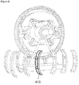
- a water blocking plate 410 may be formed as shown in FIG. 6 to prevent the pendulum weight inside the fluid tank from moving in a direction of the shaft or moving left and right even on the flat land. There may be a plurality of water blocking plates 410.
- FIG. 9 schematically illustrates a brake control system according to another exemplary embodiment, with operations on a descending slope and an ascending slope
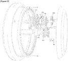
- FIG. 10 is an exploded perspective view of the brake control system of FIG. 9
- FIGS. 11 and 12 illustrate that the brake control system of FIG. 9 is mounted.
- FIGS. 9 and 10 are different in the configuration of the brake controller using the gravity, and the configurations of the deceleration and ratchet brakes coupled to the brake controller from, but have the same operations and effects as those of FIGS. 1 and 2 .
- the deceleration brake 10 may be configured to make the brake on or off according to tension of a cable
- the ratchet brake 20 may include a ratchet on the brake and a ratchet bar 230 to be caught by the ratchet according to change in tension of the cable.
- the brake controller includes a rotary body 341 to keep the buoyancy according to fluid in the fluid tank 40, and the rotary body 341 has first end coupling with a deceleration brake cable 323 and a second end coupling with a ratchet brake cable 333.
- the fluid tank 40 is not fixed but movable corresponding to change in gravity, and thus the fluid tank 40 is always maintained as it is without changing a position even in a case of movement on the slope. Therefore, the position of the fluid tank is maintained while moving the ascending or descending slope, but only the fluid filled therein leans to one side as the gravity changes.
- the fluid keeps a balance and thus the brake does not work.
- the position of the fluid tank is not changed but only the fluid in the fluid tank leans by gravity to have a low level at one side and a high level at the other side, so that one end of the rotary body 341 is lowered to keep buoyancy, thereby causing tension for pulling the deceleration brake cable 323 and making the deceleration brake 10 work as the brake cable becomes tight.
- the position of the fluid tank is not changed but only the fluid in the fluid tank leans by gravity to have a high level at one side and a low level at the other side, so that the other end of the rotary body is lowered to keep buoyancy, thereby causing tension for pulling the ratchet brake cable 333 and making the ratchet brake 20 work as the ratchet bar 230 is caught by the ratchet of the ratchet brake 20.
- FIG. 13 schematically illustrates a brake control system according to still another embodiment with operations on a descending slope and an ascending slope
- FIGS. 14 and 15 illustrate that the brake control system.
- FIGS. 13 to 15 The embodiment shown in FIGS. 13 to 15 is different just in arrangement of the deceleration brake and the ratchet brake from but has the same operations and effects as that shown in FIGS. 9 to 12 .
- FIGS. 9 to 12 shows that the deceleration brake and the ratchet brake are coaxially adjacent to each other, but this embodiment shows that the deceleration brake and the ratchet brake are arranged in parallel on different axes.
- the fluid tank 40 in this embodiment is fixedly installed and thus changed in a position (angle) according to the change of the terrain due to the slope movement (having the same structure as the embodiment shown in FIGS. 1 to 2 ) unlike that of the embodiment shown in FIGS. 9 to 12 .
- deceleration brake and the ratchet brake in this embodiment are configured to be engaged with the gear of the wheel via gears.
- the wheel includes a wheel gear 510 formed with a gear thread, and the deceleration brake 10 and the ratchet brake 20 are coupled to the gears to be engaged with the wheel gear.
- the deceleration brake 10 is externally formed with a gear thread to be coupled to a first gear 520 to be engaged with the wheel gear 510
- the ratchet brake 20 is externally formed with a gear thread to be coupled to a second gear 530 to be engaged with the wheel gear 510.
- a smart brake control system is very useful to brake industry for means for transportation with wheels because one between two different brakes is selectively operated by change in the gravity to thereby have a noticeable effect on preventing accidents while moving on a slope such as an ascending slope or a descending slope.
Landscapes
- Engineering & Computer Science (AREA)
- Mechanical Engineering (AREA)
- General Engineering & Computer Science (AREA)
- Transportation (AREA)
- Health & Medical Sciences (AREA)
- Life Sciences & Earth Sciences (AREA)
- Animal Behavior & Ethology (AREA)
- General Health & Medical Sciences (AREA)
- Public Health (AREA)
- Veterinary Medicine (AREA)
- Braking Arrangements (AREA)
- Regulating Braking Force (AREA)
Abstract
Description
- The present invention relates to a smart brake system, and more particularly to a brake automatic control system using gravity and buoyancy, which controls a brake to work in a deceleration mode on a descending slope and in a ratchet mode to prevent backward rolling on an ascending slope, thereby making safe movement even on the slopes.
- In general, a wheelchair, a baby carriage, a walker or the like means for transportation with wheels maintains a speed on a flat land but accelerates on a descending slope or rolls backward on an ascending slope, and therefore accidents frequently occur.
- In particular, the wheelchair is the transportation means used for a patient who is indisposed, and therefore accidents are highly likely to occur while the wheelchair is moving on an ascending or descending slope since the patient who sits in the wheelchair is unwell. Therefore, the wheelchair requires special attention while moving on the ascending or descending slope.
- No matter how special the attention is paid, accidents frequently occurs since it is very difficult for a patient who is indisposed to control the speed of the wheel chair on the descending or ascending slope.
- Specifically, in a case of the descending slope, the wheelchair accelerates and moves so fast that a person sitting thereon may get injured seriously by falling or secondary collision. In a case of the ascending slope, the wheelchair may roll backward while going up the ascending slope, and thus a person sitting therein may get injured seriously by falling or secondary collision.
- Further, the baby carriage is moving as pushed by a guardian from behind, and has risks of accidents while moving on the slopes like the wheelchair.
- Likewise, the bicycle for a toddler or child also has risks of accidents on the descending or ascending slope. In general, the means for transportation with the wheel has risks of accidents while moving on the slopes.
- Accordingly, the present invention is conceived to solve the foregoing problems, and an aspect of the present invention is to provide a smart brake system for safety at movement on a slope, in which the brake automatically works based on gravity and buoyancy to prevent accidents while moving on the slope as buoyancy is kept corresponding to change in gravity on a flat land, an ascending slope or a descending slope.
- In accordance with an embodiment of the present invention, there is provided a smart brake system for safety at movement on a slope, including: a multi-brake which includes a deceleration brake for working while moving on a descending slope and a ratchet brake for working while moving on an ascending slope; and a brake controller which selectively controls one of the deceleration brake and the ratchet brake to work as buoyancy of fluid is varied depending on the movement on the descending or the ascending slope.
- The multi-brake includes the deceleration brake configured to decelerate while moving on a descending slope; the ratchet brake formed to be coaxially adjacent to the deceleration brake and preventing backward rolling by ratchet locking while moving on the ascending slope; and a brake drum configured to accommodate both the deceleration brake and the ratchet brake, the brake drum including a ratchet brake accommodating portion formed with a ratchet groove corresponding to a ratchet of the ratchet brake.
- As described above, a smart brake control system according to the present invention has a noticeable effect on preventing accidents while moving on a slope such as an ascending or descending slope since one of two different brakes selectively work corresponding to change in gravity on the ascending slope or the descending slope.
-
-
FIG. 1 schematically illustrates a brake control system provided in a wheel shaft according to an exemplary embodiment of the present invention, andFIG. 2 illustrates that the brake control system ofFIG. 1 works on a descending slope and an ascending slope. -
FIG. 3 is an exploded perspective view of the brake control system ofFIG. 1 , andFIG. 4 illustrates a frame in which the brake control system ofFIG. 1 is installed. -
FIG. 5 illustrates details of a brake controller ofFIG. 1 . -
FIG. 6 illustrates water blocking plates provided in a fluid tank. -
FIG. 7 illustrates details of a deceleration brake ofFIG. 1 . -
FIG. 8 illustrates details of a ratchet brake ofFIG. 1 . -
FIG. 9 schematically illustrates a brake control system according to another embodiment, andFIG. 9 schematically illustrates a brake control system according to another exemplary embodiment, with operations on a descending slope and an ascending slope, andFIG. 10 is an exploded perspective view of the brake control system ofFIG. 9 . -
FIGS. 11 and12 illustrate that the brake control system ofFIG. 9 is mounted. -
FIG. 13 schematically illustrates a brake control system according to still another embodiment, andFIGS. 14 and15 illustrate that the brake control system ofFIG. 13 works on a descending slope and an ascending slope. - A smart brake system according to the present invention may include a first brake working on a descending slope, a second brake working on an ascending slope, and a brake controller selectively controlling one of the operations of the first and second brakes in accordance with change in gravity.
- In other words, the smart brake system may include a multi-brake, which includes a deceleration brake configured to work on the descending slope, a ratchet brake configured to work on the ascending slope, and the brake controller controlling the deceleration or ratchet brake to work as buoyancy changes in a fluid corresponding to the descending or the ascending slope.
- Below, embodiments of the present invention will be described in detail with reference to accompanying drawings.
- A smart brake system according to the present invention may be applied to a wheelchair, a baby carriage, a walker, a cart, a handcart, a handcar, a rear car, a bicycle, and the like means for transportation with a wheel, in particular any human-powered vehicles.
-
FIG. 1 schematically illustrates a brake control system provided in a wheel shaft according to an exemplary embodiment of the present invention, andFIG. 2 illustrates that the brake control system ofFIG. 1 works on a descending slope and an ascending slope. - Referring to
FIGS. 1 and 2 , the smart brake system according to the present invention may include a first brake working on a descending slope, a second brake working on an ascending slope, and a brake controller selectively controlling one of the operations of the first and second brakes in accordance with change in gravity. - In other words, the smart brake system may include a multi-brake, which includes a
deceleration brake 10 configured to work on the descending slope, aratchet brake 20 configured to work on the ascending slope, and thebrake controller 30 controlling the operation of the deceleration or ratchet brake as gravity or buoyancy changes in a fluid corresponding to the descending or the ascending slope. - The multi-brake includes the
deceleration brake 10 and theratchet brake 20, which are coaxially arranged in parallel with each other, and abrake drum 50 in which both thedeceleration brake 10 and theratchet brake 20 are accommodated. In thebrake drum 50, a portion for accommodating theratchet brake 20 is formed with a ratchet groove corresponding to a ratchet of theratchet brake 20. The ratchet and the ratchet groove may be formed to have directionality for support only unidirectional movement. When the ratchet is locked to the ratchet groove, only forward movement is allowed and backward rolling is prevented. - Therefore, when the deceleration brake works, the deceleration brake is in contact with the inner surface of the drum, thereby decreasing speed. On the other hand, when the ratchet brake works, the ratchet is contact with the ratchet groove formed inside the drum and thus the movement is stopped without the backward rolling, thereby maintaining a current position allowing the forward movement.
- That is, movement on a descending slope is controlled by the deceleration brake in a deceleration mode, and movement on an ascending slope is controlled by the ratchet brake in a ratchet mode. On the other hand, no brakes work at movement in a flat land.
- Further, the
deceleration brake 10 and theratchet brake 20 may form a pair to face each other. - The
brake controller 30 may include a fluid tank filled with fluid; arotary shaft 310 rotatably coupled to a wheel shaft; a pair offirst springs rotary shaft 310 and the pair ofdeceleration brakes 10; and a pair ofsecond springs rotary shaft 310 and the pair ofratchet brakes 20; and apendulum weight 340 coupled to therotary shaft 310, soaked in the fluid of the fluid tank, and swing left and right according to changes in the gravity of the fluid. - The
rotary shaft 310 has an elliptical shape, and one pair offirst springs second springs rotary shaft 310 and approximately perpendicular to each other. As therotary shaft 310 rotates, only one brake of the multi-brakes selectively receives force and works in such a manner that force is transmitted to only the pair offirst springs pendulum weight 340 moves forward and force is transmitted to only the pair ofsecond springs pendulum weight 340 moves backward. - Here, the pendulum weigh 340 is arranged to float in the fluid of the fluid tank by buoyancy. When the wheel is moving on the flat land, the
pendulum weight 340 is always positioned in the middle and thus no brakes work. - On the other hand, when the wheel is moving on the descending or ascending slope, the gravity acts in a direction toward low slope, the fluid leans to one side, and the
pendulum weight 340 moves in the direction of the gravity to keep the buoyancy, thereby operating the brake. - The fluid tank refers to a tank in which the fluid is filled and stored, and serves to control the operations of the multi-brakes by moving the fluid and swing the
pendulum weight 340 to keep the buoyancy as the gravity changes corresponding to the movement on the slope. - Here, the fluid may include any liquid like water, and may be materialized by blending two or more kinds of liquid.
- Further, the fluid tank may be filled with 1/4 -1/3 full of water so as to buoyancy change.
- The fluid tank is not integrally fixed and installed to the wheel but configured to rotate by the shaft. On the slope, the fluid tank rotates in the direction of the gravity, and thus the fluid tank is maintained as it is without changing a position (or angle) even in a case of movement on the slope.
- In other words, the position (or angle) of the fluid tank is maintained regardless of the movement on the slope, but the movement on the slope makes the fluid filled therein lean toward a direction where the gravity is low, thereby rotating the pendulum weight toward the direction of the low gravity to maintain the buoyancy.
- Further, the
deceleration brake 10 works while moving on the descending slope, and is provided as a pad for contacting thebrake drum 50 and decreasing the speed of the wheel. - The
ratchet brake 20 works while moving the ascending slope, and serves to put on the brake and prevent the backward rolling as the ratchet formed in theratchet brake 20 is locked to the ratchet groove formed in thebrake drum 50 when the movement is stopped. - In more detail, as shown in (a) of
FIG. 2 , in a case of the movement on the descending slope, the descending slope makes the center of gravity moves forward and thus causes the fluid injected into the fluid tank to lean forward. Therefore, thependulum weight 340 moves and swings forward as much as predetermined displacement to keep the buoyancy as the fluid moves. - Therefore, rotational force is applied to the
rotary shaft 310 connected to thependulum weight 340, and the elasticity is applied to thefirst springs rotary shaft 310 so that thedeceleration brake 10 works to come into contact with the brake drum, thereby decreasing the speed. - Here, unlike the brake of the bicycle, the speed does not become zero but decreases as the deceleration brake is in contact with the brake drum. In this manner, the deceleration speed may be previously set by controlling the contact area and force between the deceleration brake and the brake drum.
- Further, as shown in (b) of
FIG. 2 in a case of the movement on the ascending slope, the ascending slope causes the fluid filled in the fluid tank to lean to the opposite direction, i.e. backward. Therefore, thependulum weight 340 also moves in the opposite direction, i.e. backward and makes the gravity change in the opposite direction to keep the buoyancy. - Therefore, rotational force is applied to the
rotary shaft 310 connected to thependulum weight 340 in the opposite direction, and the elasticity is applied to thesecond springs rotary shaft 310 so that theratchet brake 20 works to thereby lock the ratchet of theratchet brake 20 to the ratchet groove formed in the brake drum. The ratchet and the ratchet groove are formed to allow only the unidirectional movement, and thus the wheel is movable forward but immovable backward. - Accordingly, the wheel is prevented from backward rolling and allowed to move in the ascending direction since the ratchet is locked to the ratchet groove even when the wheel stops moving on the ascending slope, thereby guaranteeing the safety.
- Further, according to the present invention, a
water blocking plate 410 may be formed as shown inFIG. 6 to prevent the pendulum weight inside the fluid tank from moving in a direction of the shaft or moving left and right even on the flat land. There may be a plurality ofwater blocking plates 410. -
FIG. 9 schematically illustrates a brake control system according to another exemplary embodiment, with operations on a descending slope and an ascending slope, andFIG. 10 is an exploded perspective view of the brake control system ofFIG. 9 .FIGS. 11 and12 illustrate that the brake control system ofFIG. 9 is mounted. - The embodiment of
FIGS. 9 and10 are different in the configuration of the brake controller using the gravity, and the configurations of the deceleration and ratchet brakes coupled to the brake controller from, but have the same operations and effects as those ofFIGS. 1 and 2 . - Thus, only different configurations from those of
FIGS. 1 and 2 will be described. - In this embodiment, there are no elements corresponding to the brake drum, and thus the deceleration brake and the ratchet brake work in itself to have the deceleration or ratchet function.
- To this end, the
deceleration brake 10 may be configured to make the brake on or off according to tension of a cable, and theratchet brake 20 may include a ratchet on the brake and aratchet bar 230 to be caught by the ratchet according to change in tension of the cable. - Further, the brake controller includes a
rotary body 341 to keep the buoyancy according to fluid in thefluid tank 40, and therotary body 341 has first end coupling with adeceleration brake cable 323 and a second end coupling with aratchet brake cable 333. - Further, the
fluid tank 40 is not fixed but movable corresponding to change in gravity, and thus thefluid tank 40 is always maintained as it is without changing a position even in a case of movement on the slope. Therefore, the position of the fluid tank is maintained while moving the ascending or descending slope, but only the fluid filled therein leans to one side as the gravity changes. - Here, when the
rotary body 341 is in the flat land, the fluid keeps a balance and thus the brake does not work. While moving on the descending slope, the position of the fluid tank is not changed but only the fluid in the fluid tank leans by gravity to have a low level at one side and a high level at the other side, so that one end of therotary body 341 is lowered to keep buoyancy, thereby causing tension for pulling thedeceleration brake cable 323 and making thedeceleration brake 10 work as the brake cable becomes tight. - On the other hand, while moving on the ascending slope, the position of the fluid tank is not changed but only the fluid in the fluid tank leans by gravity to have a high level at one side and a low level at the other side, so that the other end of the rotary body is lowered to keep buoyancy, thereby causing tension for pulling the
ratchet brake cable 333 and making theratchet brake 20 work as theratchet bar 230 is caught by the ratchet of theratchet brake 20. -
FIG. 13 schematically illustrates a brake control system according to still another embodiment with operations on a descending slope and an ascending slope, andFIGS. 14 and15 illustrate that the brake control system. - The embodiment shown in
FIGS. 13 to 15 is different just in arrangement of the deceleration brake and the ratchet brake from but has the same operations and effects as that shown inFIGS. 9 to 12 . - Therefore, only differences from the embodiment of
FIGS. 9 to 12 will be described. - The embodiment of
FIGS. 9 to 12 shows that the deceleration brake and the ratchet brake are coaxially adjacent to each other, but this embodiment shows that the deceleration brake and the ratchet brake are arranged in parallel on different axes. - Further, the
fluid tank 40 in this embodiment is fixedly installed and thus changed in a position (angle) according to the change of the terrain due to the slope movement (having the same structure as the embodiment shown inFIGS. 1 to 2 ) unlike that of the embodiment shown inFIGS. 9 to 12 . - Further, the deceleration brake and the ratchet brake in this embodiment are configured to be engaged with the gear of the wheel via gears.
- The wheel includes a
wheel gear 510 formed with a gear thread, and thedeceleration brake 10 and theratchet brake 20 are coupled to the gears to be engaged with the wheel gear. - In more detail, the
deceleration brake 10 is externally formed with a gear thread to be coupled to afirst gear 520 to be engaged with thewheel gear 510, and theratchet brake 20 is externally formed with a gear thread to be coupled to asecond gear 530 to be engaged with thewheel gear 510. - Although a few exemplary embodiments of the present invention have been described with reference to the accompanying drawings, it will be appreciated by those skilled in the art that various changes or modifications may be made in these embodiments without departing from the principles and spirit of the invention, the scope of which is defined in the appended claims and their equivalents.
- A smart brake control system according to the present invention is very useful to brake industry for means for transportation with wheels because one between two different brakes is selectively operated by change in the gravity to thereby have a noticeable effect on preventing accidents while moving on a slope such as an ascending slope or a descending slope.
Claims (10)
- A smart brake system for safety at movement on a slope, comprising:a multi-brake which comprises a deceleration brake for working while moving on a descending slope and a ratchet brake for working while moving on an ascending slope;a brake controller which selectively controls one of the deceleration brake and the ratchet brake to work as buoyancy of fluid is varied depending on the movement on the descending or the ascending slope.
- The smart brake system according to claim 1, wherein
the multi-brake comprises
a deceleration brake configured to decelerate while moving on a descending slope;
a ratchet brake formed to be coaxially adjacent to the deceleration brake and preventing backward rolling by ratchet locking while moving on an ascending slope; and
a brake drum configured to accommodate both the deceleration brake and the ratchet brake, the brake drum comprising a ratchet brake accommodating portion formed with a ratchet groove corresponding to a ratchet of the ratchet brake. - The smart brake system according to claim 2, wherein the brake controller comprising
a fluid tank filled with fluid;
a rotary shaft rotatably coupled to a wheel shaft;
a pair of first springs connected to the rotary shaft and one pair of deceleration brakes, respectively;
a pair of second springs connected to the rotary shaft and one pair of ratchet brakes, respectively; and
a rotary weight coupled to the rotary shaft, soaked in the fluid of the fluid tank, and move leftward and rightward to keep buoyancy as the fluid is varied in gravity. - The smart brake system according to claim 3, wherein
the pair of first springs and the pair of second springs coupled to the rotary shaft and approximately perpendicular to each other, and
only one kind of brake of the multi-brake receives force and works as the rotary shaft rotates in such a manner that the deceleration brake works as force is transmitted to only the pair of first springs when the pendulum weight moves forward corresponding to descending movement, and the ratchet brake works as force is transmitted to only the pair of second springs when the pendulum weight moves backward corresponding to ascending movement - The smart brake system according to claim 1, wherein the multi-brake comprises:a deceleration brake configured to make a brake on or off according to tension of a cable; anda ratchet brake comprising a ratchet formed on a brake and a ratchet bar to be caught by the ratchet according to change in tension of the cable,wherein the deceleration brake and the ratchet brake are coaxially arranged in parallel.
- The smart brake system according to claim 5, wherein the brake controller comprises:a fluid tank which is not integrally fixed and installed to the wheel but configured to rotate with respect to a shaft, and rotates in a direction of gravity on a slope, so that a position (or angle) of the fluid tank is always maintained without change corresponding to the direction of the gravity even in a case of movement on the slope; anda rotary body which rotates to keep buoyancy according to change of the fluid in the fluid tank,wherein the rotary body has a first end coupling with a deceleration brake cable, and a second end coupling with a ratchet brake cable.
- The smart brake system according to claim 6, wherein,
the brake does not work since the fluid keeps a balance and thus when the rotary body is in the flat land,
the deceleration brake works since a brake cable becomes tight by tension generated to pull the deceleration brake cable as the position of the fluid tank is not changed but only the fluid in the fluid tank leans by gravity to have a low level at one side and a high level at the other side so that one end of the rotary body is lowered to keep buoyancy while moving on the descending slope, and
the ratchet brake works since the ratchet bar is caught by the ratchet of the ratchet brake by tension generated to pull the ratchet brake cable as the position of the fluid tank is not changed but only the fluid in the fluid tank leans by gravity to have a high level at one side and a low level at the other side so that the other end of the rotary body is lowered to keep buoyancy while moving on the ascending slope. - The smart brake system according to claim 1, wherein the multi-brake comprises:a deceleration brake formed with a gear thread; anda ratchet brake formed with a gear thread;wherein the deceleration brake and the ratchet brake are arranged in parallel on different axes.
- The smart brake system according to claim 8, wherein the brake controller comprises:a fluid tank;a rotary body which rotates to keep buoyancy according to change of the fluid in the fluid tank, wherein the rotary body has a first end coupling with a deceleration brake cable, and a second end coupling with a ratchet brake cable;a wheel gear formed with a gear thread on a wheel;a first gear formed between the deceleration brake and the wheel gear; anda second gear formed between the ratchet brake and the wheel gear.
- The smart brake system according to claim 2 or 9, wherein the fluid tank is fixedly installed and has a structure of being changed in a position (angle) according to the change of the terrain due to the slope movement.
Applications Claiming Priority (3)
| Application Number | Priority Date | Filing Date | Title |
|---|---|---|---|
| KR20160056808 | 2016-05-10 | ||
| KR1020160061196A KR101684320B1 (en) | 2016-05-10 | 2016-05-19 | Smart Brake System |
| PCT/KR2016/014055 WO2017195959A2 (en) | 2016-05-10 | 2016-12-01 | Smart brake system for safety when moving on slope |
Publications (2)
| Publication Number | Publication Date |
|---|---|
| EP3456594A2 true EP3456594A2 (en) | 2019-03-20 |
| EP3456594A4 EP3456594A4 (en) | 2019-11-20 |
Family
ID=57577010
Family Applications (1)
| Application Number | Title | Priority Date | Filing Date |
|---|---|---|---|
| EP16901792.8A Withdrawn EP3456594A4 (en) | 2016-05-10 | 2016-12-01 | INTELLIGENT BRAKE SYSTEM FOR SAFETY DURING SLOPE TRAVEL |
Country Status (6)
| Country | Link |
|---|---|
| US (1) | US10857048B2 (en) |
| EP (1) | EP3456594A4 (en) |
| JP (1) | JP6885613B2 (en) |
| KR (1) | KR101684320B1 (en) |
| CN (1) | CN109153372B (en) |
| WO (1) | WO2017195959A2 (en) |
Families Citing this family (11)
| Publication number | Priority date | Publication date | Assignee | Title |
|---|---|---|---|---|
| KR101787641B1 (en) | 2017-03-30 | 2017-10-19 | 주식회사 올비트앤 | Apparatus for decelerating a wheel by detecting a slope of a road |
| CN110588871B (en) * | 2019-10-22 | 2020-04-07 | 东阳坪洲电动车科技有限公司 | Induction type electric vehicle auxiliary brake |
| JP6742493B1 (en) * | 2019-11-29 | 2020-08-19 | 合同会社ライフスペース研究所 | Wheelchair that can be operated with one hand |
| DE102020105874B3 (en) * | 2020-03-04 | 2021-05-06 | Thomas Birmanns | BRAKE DEVICE |
| CN111425535B (en) * | 2020-04-08 | 2021-06-04 | 桂林电子科技大学 | Hierarchical formula drum brake |
| CN112168523B (en) * | 2020-09-14 | 2023-01-13 | 高敏丽 | Automatic slope speed control mechanism for common wheelchair |
| CN112498543B (en) * | 2020-12-07 | 2022-02-22 | 苏州市职业大学 | Baby carrier slope anti-overturning device |
| US11854434B2 (en) * | 2021-06-19 | 2023-12-26 | Danny Baldwin | Virtual reality vehicle operation simulation |
| JP7330335B1 (en) | 2022-08-03 | 2023-08-21 | 蘇建忠 | automatic deceleration wheel body |
| US12220944B2 (en) * | 2022-08-18 | 2025-02-11 | Chien-Chung Su | Automatic speed reducing wheel |
| KR102808920B1 (en) * | 2023-06-29 | 2025-05-15 | 경성대학교 산학협력단 | A safety wheel |
Family Cites Families (27)
| Publication number | Priority date | Publication date | Assignee | Title |
|---|---|---|---|---|
| US2934381A (en) * | 1959-01-28 | 1960-04-26 | Kelsey Hayes Co | Booster brake system |
| FR1600143A (en) * | 1968-12-31 | 1970-07-20 | ||
| JPS60174660U (en) * | 1984-04-27 | 1985-11-19 | ヤンマー農機株式会社 | work vehicle |
| DE3538535A1 (en) * | 1985-10-30 | 1987-05-07 | Alfred Giesau | PARKING BRAKE FOR WHEELCHAIR WHEELS |
| FR2635296B1 (en) * | 1988-08-12 | 1992-07-24 | Caddie Atel Reunis | WHEEL FOR TROLLEY OR THE LIKE HAVING A LOCKING DEVICE ON AN INCLINED PLANE |
| US4934490A (en) * | 1989-03-14 | 1990-06-19 | Chang Deng J | Anti-roll device for vehicles |
| JPH04110240A (en) * | 1990-08-31 | 1992-04-10 | Hino Motors Ltd | Device for assisting start at ascent |
| US5301971A (en) * | 1992-02-24 | 1994-04-12 | Brereton H Arthur | Ratcheting wheelchair hub |
| KR940014070A (en) * | 1992-12-02 | 1994-07-16 | 김택진 | Bicycle power storage device |
| KR19980012513U (en) * | 1996-08-27 | 1998-06-05 | 박병재 | Hydraulic Parking Brake System |
| US5845746A (en) * | 1996-12-13 | 1998-12-08 | Henrickson; Sarah E. | Wheelchair dynamic braking system |
| JPH1159113A (en) * | 1997-08-25 | 1999-03-02 | Mein Kk | Caster with brake |
| CN2350726Y (en) * | 1999-01-14 | 1999-11-24 | 中国矿业大学(北京校区) | Spheric ring grating moire orientation inclinometer |
| JP2001347885A (en) * | 1999-08-06 | 2001-12-18 | Nobuo Komori | Braking notifying device for vehicle to succeeding traveling vehicle, and reduction gear ratio detector used therefor |
| JP2003090362A (en) * | 2001-09-18 | 2003-03-28 | Akebono Brake Ind Co Ltd | Braking device |
| TW521129B (en) * | 2000-08-18 | 2003-02-21 | Akebono Brake Ind | Braking device |
| KR20020052304A (en) * | 2000-12-26 | 2002-07-04 | 이계안 | Braking method parking break system of vehicle |
| US7316298B2 (en) * | 2002-04-29 | 2008-01-08 | The United States Of America As Represented By The Secretary Of The Army | Wheelchair safety brake assembly |
| US6899212B2 (en) * | 2002-08-06 | 2005-05-31 | Tianfu Li | Device for holding a wheel against rotation on an inclined surface |
| CN100382996C (en) * | 2006-02-07 | 2008-04-23 | 阴贵生 | Emergency support air sac cushion device and method for preventing auto rolling |
| KR20090057338A (en) * | 2007-12-02 | 2009-06-05 | 김재환 | Automatic speed control method and device |
| CN201266083Y (en) * | 2008-09-17 | 2009-07-01 | 东莞市美满传感器科技有限公司 | Electromagnetic induction type contactless inclination sensor |
| DE102010029337A1 (en) * | 2009-07-16 | 2011-02-03 | Continental Teves Ag & Co. Ohg | Assembly consisting of a pressure medium reservoir and a manually operable master cylinder, in particular for a hydraulic motorcycle brake system |
| CN201583275U (en) * | 2009-12-22 | 2010-09-15 | 陈天歌 | Road grade instrument for vehicle |
| JP6083599B2 (en) * | 2013-01-30 | 2017-02-22 | 本田技研工業株式会社 | Inclination detection device for vehicle |
| ES1112530Y (en) * | 2014-03-20 | 2014-09-08 | Garcia Miguel Garcia | BRAKING MECHANISM IN PENDING, FOR CARS, CARS OR CHAIRS |
| KR101536708B1 (en) * | 2014-10-13 | 2015-07-14 | 주식회사 올비트앤 | Apparatus for decelerating a wheel by detecting a slope of a road |
-
2016
- 2016-05-19 KR KR1020160061196A patent/KR101684320B1/en not_active Expired - Fee Related
- 2016-12-01 EP EP16901792.8A patent/EP3456594A4/en not_active Withdrawn
- 2016-12-01 JP JP2018559382A patent/JP6885613B2/en not_active Expired - Fee Related
- 2016-12-01 WO PCT/KR2016/014055 patent/WO2017195959A2/en not_active Ceased
- 2016-12-01 CN CN201680085576.XA patent/CN109153372B/en not_active Expired - Fee Related
- 2016-12-01 US US16/099,439 patent/US10857048B2/en not_active Expired - Fee Related
Also Published As
| Publication number | Publication date |
|---|---|
| US20190142663A1 (en) | 2019-05-16 |
| JP2019521287A (en) | 2019-07-25 |
| US10857048B2 (en) | 2020-12-08 |
| CN109153372A (en) | 2019-01-04 |
| JP6885613B2 (en) | 2021-06-16 |
| WO2017195959A2 (en) | 2017-11-16 |
| EP3456594A4 (en) | 2019-11-20 |
| CN109153372B (en) | 2021-06-11 |
| KR101684320B1 (en) | 2016-12-08 |
| WO2017195959A3 (en) | 2018-03-08 |
Similar Documents
| Publication | Publication Date | Title |
|---|---|---|
| US10857048B2 (en) | Smart brake system for safety at slope | |
| EP1539563B1 (en) | Tilting vehicle | |
| EP3395659B1 (en) | Safe two-wheeled self-balancing vehicle | |
| KR101330172B1 (en) | Coaxil two-wheel vehicle and method for controlling same | |
| EP2356016B1 (en) | Apparatus and method for control of a dynamically self-balancing vehicle | |
| US7810591B2 (en) | Traveling device | |
| WO2014188726A1 (en) | Electric walking assistance device, program for controlling electric walking assistance device, and method of controlling electric walking assistance device | |
| JP2007062682A (en) | Traveling body | |
| US9845101B2 (en) | Pushcart | |
| US10945900B1 (en) | Powered wheelchair for beach terrain | |
| US4374548A (en) | Playing vehicle with a prime mover | |
| KR20190100015A (en) | Wheel chair having an auxiliary force generating device | |
| KR20210060950A (en) | Auxiliary power unit for manual wheelchair | |
| JP7220811B2 (en) | A vehicle with an electric braking mechanism, a wheel unit, and a program for controlling the wheel unit | |
| JP5262935B2 (en) | Coaxial motorcycle | |
| US7175501B2 (en) | Children's car driven by swiveling operations of a steering wheel | |
| JP2018167827A (en) | Autonomous driving vehicle | |
| JP6511545B2 (en) | Braking device with ramp sensing and deceleration function | |
| KR20100134950A (en) | Bicycle without hand operation | |
| KR101640431B1 (en) | Front and rear-wheel drive type safty bicycle | |
| KR20140118089A (en) | Bicycle with baby carriage | |
| KR20130025100A (en) | Transfer apparatus | |
| EP3546317A1 (en) | Braking mechanism for transferring means for children | |
| KR20240132724A (en) | Smart Stroller with Automatic Braking and Power Auxiliary Means | |
| JP2006021693A (en) | Rear car bicycle |
Legal Events
| Date | Code | Title | Description |
|---|---|---|---|
| STAA | Information on the status of an ep patent application or granted ep patent |
Free format text: STATUS: THE INTERNATIONAL PUBLICATION HAS BEEN MADE |
|
| PUAI | Public reference made under article 153(3) epc to a published international application that has entered the european phase |
Free format text: ORIGINAL CODE: 0009012 |
|
| STAA | Information on the status of an ep patent application or granted ep patent |
Free format text: STATUS: REQUEST FOR EXAMINATION WAS MADE |
|
| 17P | Request for examination filed |
Effective date: 20181210 |
|
| AK | Designated contracting states |
Kind code of ref document: A2 Designated state(s): AL AT BE BG CH CY CZ DE DK EE ES FI FR GB GR HR HU IE IS IT LI LT LU LV MC MK MT NL NO PL PT RO RS SE SI SK SM TR |
|
| AX | Request for extension of the european patent |
Extension state: BA ME |
|
| DAV | Request for validation of the european patent (deleted) | ||
| DAX | Request for extension of the european patent (deleted) | ||
| A4 | Supplementary search report drawn up and despatched |
Effective date: 20191023 |
|
| RIC1 | Information provided on ipc code assigned before grant |
Ipc: B60T 7/12 20060101AFI20191017BHEP Ipc: F16D 59/00 20060101ALI20191017BHEP Ipc: F16D 65/14 20060101ALI20191017BHEP Ipc: F16H 1/10 20060101ALI20191017BHEP Ipc: B60T 8/24 20060101ALI20191017BHEP Ipc: A61G 5/04 20130101ALI20191017BHEP Ipc: A61G 5/10 20060101ALI20191017BHEP |
|
| STAA | Information on the status of an ep patent application or granted ep patent |
Free format text: STATUS: THE APPLICATION IS DEEMED TO BE WITHDRAWN |
|
| 18D | Application deemed to be withdrawn |
Effective date: 20220701 |