EP3456567B1 - Compartiment de transport de marchandise à porte sectionnelle et véhicule comprenant un tel compartiment - Google Patents
Compartiment de transport de marchandise à porte sectionnelle et véhicule comprenant un tel compartiment Download PDFInfo
- Publication number
- EP3456567B1 EP3456567B1 EP18195535.2A EP18195535A EP3456567B1 EP 3456567 B1 EP3456567 B1 EP 3456567B1 EP 18195535 A EP18195535 A EP 18195535A EP 3456567 B1 EP3456567 B1 EP 3456567B1
- Authority
- EP
- European Patent Office
- Prior art keywords
- compartment
- roof
- roller shutter
- apron
- opening
- Prior art date
- Legal status (The legal status is an assumption and is not a legal conclusion. Google has not performed a legal analysis and makes no representation as to the accuracy of the status listed.)
- Active
Links
Images



Classifications
-
- B—PERFORMING OPERATIONS; TRANSPORTING
- B60—VEHICLES IN GENERAL
- B60J—WINDOWS, WINDSCREENS, NON-FIXED ROOFS, DOORS, OR SIMILAR DEVICES FOR VEHICLES; REMOVABLE EXTERNAL PROTECTIVE COVERINGS SPECIALLY ADAPTED FOR VEHICLES
- B60J5/00—Doors
- B60J5/10—Doors arranged at the vehicle rear
- B60J5/12—Doors arranged at the vehicle rear slidable; foldable
- B60J5/14—Doors arranged at the vehicle rear slidable; foldable of roller-blind type made of rigid elements
-
- B—PERFORMING OPERATIONS; TRANSPORTING
- B60—VEHICLES IN GENERAL
- B60J—WINDOWS, WINDSCREENS, NON-FIXED ROOFS, DOORS, OR SIMILAR DEVICES FOR VEHICLES; REMOVABLE EXTERNAL PROTECTIVE COVERINGS SPECIALLY ADAPTED FOR VEHICLES
- B60J5/00—Doors
- B60J5/10—Doors arranged at the vehicle rear
- B60J5/12—Doors arranged at the vehicle rear slidable; foldable
- B60J5/125—Doors arranged at the vehicle rear slidable; foldable for utility vehicles or public transport
Definitions
- the present invention relates to a cargo transport compartment as defined in the preamble of claim 1.
- the invention also relates to a goods transport vehicle comprising such a compartment.
- the hinged door compartments include two sides and a roof connecting the two sides, the sides defining between them an opening for access of goods inside the compartment, and leaves with vertical axes to open and close said opening.
- This type of compartment has many drawbacks, in particular because the leaves require a large clearance to be able to be opened, clearance rarely present near the loading / unloading docks of trucks. This implies that, often, the leaves must be opened at a distance from the loading / unloading dock, then the truck backed up to the dock, with the risk of goods falling through the opening thus left clear. In addition, when the compartment is refrigerated, it requires excessive energy consumption to maintain the desired temperature inside the compartment under penalty of breaking the cold chain. Another drawback is that the opening and closing of the compartment most often require direct manual intervention by a user, generally the driver of the truck.
- sectional door compartments have been developed. These compartments do in fact require no clearance to be able to be opened, so that they can be opened even in confined spaces. In addition, sectional doors can be easily automated.
- the known sectional door compartments suffer from a circulation space reduced in width.
- the frame necessarily has uprights to be able to guide the apron to its closed position, said uprights cooperating with guide members carried by the slats of the apron.
- these guide members cannot encroach laterally outside the opening, otherwise they could not follow the slats of the apron inside the compartment when the apron is opened. Therefore, the uprights of the frame must be offset towards the inside of the opening relative to the sides in order to be able to cooperate with said guide members.
- the circulation space, defined between the uprights is narrower than the opening.
- the solution described is not entirely satisfactory. Indeed, it requires the installation of structures on top of the roof which increase the height of the compartment and can pose traffic problems and homologation problems of the truck on which it is mounted. In addition, it requires the length of the pavilion to be shortened in order to be able to be mounted. In addition, it requires an apron narrow enough to be able to penetrate inside the space defined between the sidewalls, which, in order to be able to seal around the apron when it is in the closed position, requires positioning the uprights so that they encroach on the circulation space, thus reducing the width. Finally, this solution is complex and expensive to implement.
- An objective of the invention is to provide a cargo transport compartment with a sectional door having a loading capacity and a maximized circulation space. Other objectives are to minimize the height gain of the compartment related to the installation of structures on top of the pavilion and to minimize the cost of such a compartment.
- the subject of the invention is a compartment for transporting goods of the aforementioned type, comprising the characteristics of the characterizing part of claim 1.
- the subject of the invention is also a goods transport vehicle comprising a goods transport compartment as defined above.
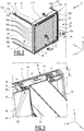
- the goods transport vehicle 10 shown in Figure 1 consists of a motor vehicle, commonly called a "truck", comprising a compartment 12 intended to receive goods, a cabin 14, wheels 16, and a frame 18.
- a motor vehicle commonly called a "truck”
- a compartment 12 intended to receive goods
- a cabin 14 wheels
- a frame 18 a frame
- the compartment 12 comprises two vertical sides 20 spaced transversely from one another (only the left sidewall 20 appearing in the Figure), a horizontal roof 22 connecting the upper edges of the two sidewalls 20, and a floor 24 connecting the ends of the two sidewalls 20.
- the sidewalls 20, the roof 22 and the floor 24 together define a rear opening 26 for the access of goods to the interior of the compartment 12.
- the flanks 20 each have, at the level of the opening 26, a thickness e 1 ( Figure 3 ), taken in the transverse direction Y, this thickness e 1 being substantially the same for the two sides 20.
- the thickness e 1 is between 60 and 70 mm.
- the pavilion 22, for its part, at the level of the opening 26 has a thickness e 2 ( Figure 4 ) taken in the vertical direction Z between a lower face 23 ( Figure 4 ) and an upper face 25 ( Figure 4 ), substantially flat, of the pavilion 22.
- the thickness e 2 is between 120 and 125 mm.
- Compartment 12 is in particular a refrigerated compartment.
- the compartment 12 also includes a sectional door 28 capable of selectively opening and closing the opening 26.
- the sectional door 28 comprises a frame 29 framing the opening 26, and an apron 30 movably mounted relative to the frame 29 between a closed position, in which the apron 30 is substantially vertical and closes the opening 26 , and an open position, in which the apron 30 is substantially horizontal and rests on the upper face 25 of the pavilion 22, away from the opening 26.
- the frame 29 has a proximal end 32 at which the apron 30 is positioned when it is in the open position, and a distal end 33 opposite the proximal end 32.
- the frame 29 comprises two lateral uprights 36 each arranged longitudinally in the extension of a respective sidewall 20, an upper cross member 37 disposed longitudinally in the extension of the roof 22, and a lower outer 38.
- the upper and lower cross members 37, 38 connect respectively the upper and lower ends of the two uprights 36.
- the upper cross member 37 here defines the proximal end 32 of the frame 30, and the lower cross member 38 defines the distal end 33.
- each upright 36 has successively, from the front to the rear, a base 40 for connection to a respective sidewall 20, an intermediate portion 41, and an end portion 42 defining a rear end of the upright 36.
- base 40, portion intermediate 41 and end portion 42 are preferably formed together in one piece, typically by extrusion.
- the base 40, the intermediate portion 41 and the end portion 42 fit longitudinally in the extension of each other and in the extension of the sidewall 20.
- the end portion 42 has over substantially its entire height a transverse width I, taken in the transverse direction Y, preferably between 70 and 75 mm.
- the transverse width I is substantially equal to said thickness ei, that is to say that the ratio of the transverse width I to the thickness of flank e 1 is between 0.80 and 1.25.
- This transverse width I constitutes the maximum transverse width of the upright 36.
- the upright 36 does not encroach on the opening 26, so that the circulation space defined between the uprights 36 is maximized.
- the intermediate portion 41 has for its part a width less than the width I , in particular less than 50% of said width I.
- the amount 36 defines between the end portion 42 and the side 20 a cavity 43, opening onto the opening 26, suitable for receiving the apron 30, the intermediate portion 41 forming the bottom of said cavity 43.
- Each upright 36 also includes a guide rail 44 suitable for guiding the movement of the apron 30 between its open and closed positions.
- This guide rail 44 is preferably formed integrally with the intermediate portion 41.
- This guide rail 44 is positioned inside the cavity 43. It has a substantially rectilinear shape and extends substantially vertically throughout the height of the upright 36.
- the upper cross member 37 comprises a base 45 for connection to the roof 22 and a rear transverse beam 46 and defines, between said base 45 and said rear transverse beam 46, a passage 47 for the apron 30 between its open and closed positions. closing.
- the upper cross member 37 also has a lower face 48 and an upper face 49.
- the lower face 48 is substantially flush with the lower face 23 of the flag 22, that is to say the vertical gap between the faces 48 and 23 is less than 10 mm.
- the upper cross member 37 does not encroach on the opening 36, so that the circulation space defined between the cross members 37, 38 is maximized.
- the upper face 49 is for its part disposed above the plane of the upper face 25 of the flag 22.
- the vertical distance between said upper face 49 and the upper face 25 of the flag 22 is less than 40 mm and is in particular between 25 and 30 mm.
- the passage 47 opens out through a lower slot 50 in the lower face 48 of the cross member 37, and through an upper window 51 in the upper face 49 of the cross member 37, the slot 50 and the window 51 each being elongated in the direction transverse Y.
- the cross member 37 does not include a base 45, a covering sheet being instead attached to the roof 22.
- the passage 47 is then defined between the upper cross member 37 and the roof 22.
- the apron 30 has an outer face 54 oriented towards the outside of the compartment 12, and an inner face 55 oriented towards the inside of the compartment 12.
- the apron 30 also has a first end 56 which, when the apron 30 is in the closed position, forms an upper end of the apron 30, and a second end 57 ( Figure 2 ) opposite to the first end 56 and which, when the apron 30 is in the closed position, forms a lower end of the apron 30.
- the apron 30 comprises a plurality of strips 58a, 58b arranged successively between the first and second ends 56, 57 and articulated to each other by hinges 59.
- the apron 30 also comprises, for each strip 58a, 58b, two guide members 60, each adapted to cooperate with the guide rail 44 of a respective upright 36 to guide the movements of the apron 30.
- sipes 58a, 58b include end sipes 58b, one defining the first end 56 and the other defining the second end 57, and a plurality of intermediate sipes 58a interposed between the end sipes 58b.
- the slats 58a, 58b are essentially identical to each other.
- the description of the intermediate strips 58a given below is therefore, unless explicitly mentioned, applicable to the end strips 58b.
- Each intermediate strip 58a is elongated in the transverse direction Y and extends the entire width of the opening 26, its transverse ends 61 ( Figure 3 ) each being received in the cavity 43 by a respective amount 36.
- each strip 58a comprises a body 62, a fastening member 63 and a connecting member 64 connecting the fastening member to the body 62.
- the body 62 is made of a rigid plastic material, for example polycarbonate (PC), acrylonitrile butadiene styrene (ABS), or Acrylonitrile Styrene Acrylate (ASA). As a variant (not shown), it is made of a metallic material.
- PC polycarbonate
- ABS acrylonitrile butadiene styrene
- ASA Acrylonitrile Styrene Acrylate
- the body 62 is elongated in the transverse direction Y and extends from a transverse end 61 of the lamella 58a to the opposite transverse end 61.
- the body 62 is hollow and defines a chamber 65 filled with a thermally insulating material 66, for example a foam.
- the body 62 is of general parallelepipedal shape with a large inner face 67 oriented towards the inside of the compartment 12, a large outer face 68 oriented towards the outside of the compartment 12 and substantially parallel to the large inner face 67, a first small face 69 joining the large faces 67, 68 to each other, said first small face 69 forming an upper face of the body 62 when the apron 30 is in the closed position, and a second small face 70 joining the large faces 67, 68 to each other, said second small face 70 being opposite to the first small face 69 and forming a lower face of the body 62 when the apron 30 is in the closed position.
- the large inner faces 67 of the bodies 62 of the different slats 58a, 58b together form the inner face 55 of the apron 30, and the large outer faces 68 of the bodies 62 of the different slats 58a, 58b together form the outer face 54 of the apron 30.
- the body 62 has a fastening element 71 having a shape complementary to that of the fastening member 63.
- This fastening element 71 is here formed by a tubular cavity 72, oriented in the transverse direction Y, of vertical section. substantially complementary to that of the hooking member 63 and opening through a transverse slot 73 in the second small face 70 of the body 62.
- the hooking element 71 is arranged along an inner edge 74 of the second small face 70, formed by the edge connecting the second small face 70 to the inner face 67.
- the body 62 also has a groove 75 elongated in the transverse direction Y and formed in the second small face 70, between the fastening element 71 and the outer face 62.
- This groove 75 here has a substantially V-shaped vertical section. It has at its bottom a screw shaft 75A elongated in the transverse direction Y.
- the body 62 also has a lip 76 elongated in the transverse direction Y and projecting from the first small face 69 opposite the chamber 65. It is substantially aligned with the groove 75 along a plane parallel to the faces 67, 68 and has a vertical section substantially complementary to the section of the groove 75. It has at its tip a screwing shank 76A elongated in the transverse direction Y.
- the body 62 also has an element 77 for fixing the guide members 60 on the strip 58a.
- This fixing element 77 is here formed by a tubular cavity 78, oriented in the transverse direction Y, of substantially discoidal vertical section, and opening through a transverse slot 79 in the first small face 69 of the body 62.
- the hooking element 77 is disposed along an inner edge 80 of the first small face 69, formed by the edge connecting the first small face 69 to the inner face 67.
- the body 62 also has a rib 81 elongated in the transverse direction Y and projecting from the second small face 70 opposite the chamber 65, substantially parallel to the faces 67, 68.
- This rib 81 is in particular disposed along the side of the chamber.
- 'an outer edge 82 of the second small face 70 formed by the edge connecting the second small face 70 to the outer face 68.
- the fastening member 63 is also made of a rigid plastic material, for example polycarbonate (PC), acrylonitrile butadiene styrene (ABS) or Acrylonitrile Styrene Acrylate (ASA). It is in particular made of the same plastic material as the body 62.
- PC polycarbonate
- ABS acrylonitrile butadiene styrene
- ASA Acrylonitrile Styrene Acrylate
- the hooking member 63 is elongated in the transverse direction Y and preferably extends from a transverse end 61 of the strip 58a to the opposite transverse end 61.
- the fastening member 63 comprises a wide head 83 connected by a narrow elbow 84 to the connecting member 64.
- the head 83 has a vertical section substantially complementary to that of the cavity 72 of the fastening element 71.
- the connecting member 64 is made of flexible material, typically polyurethane (PU). It is elongated in the transverse direction Y and preferably extends from a transverse end 61 of the lamella 58a to the opposite transverse end 61.
- PU polyurethane
- the connecting member 64 is connected to the body 62 along the inner edge 80 of the first small face 69.
- the fastening member 63 cooperates with the fastening element 71 of the adjacent strip 58a, 58b disposed immediately above when the apron 30 is in the closed position having its head 83 received in the cavity 72. This is not the case for the end strip 58b defining the first end 56 since the latter does not have a strip disposed immediately above. above when the apron 30 is in the closed position.
- the strips 58a, 58b are made integral with each other by the cooperation of the fastening members 63 with the fastening elements 71, the connecting members 64 conferring the flexibility allowing the articulation of the various strips 58a, 58b them. relative to each other and thereby constituting the hinges 59.
- the body 62, the hooking member 63 and the connecting member 64 are in particular formed together by coextrusion of plastics. This solution allows excellent holding of the hinges 59, at the same time as it is particularly economical.
- Each strip 58a also comprises two reinforcements 85, 86, each elongated in the transverse direction Y, including a first reinforcement 85 housed in the chamber 65 against the first small face 69, between the connecting member 64 and the lip 76, and a second reinforcement 86 housed in the chamber 65 against the second small face 70, between the fastening element 71 and the groove 75.
- Each reinforcement 85, 86 is for example made of steel, or of pultruded.
- Each strip 58a further comprises a flexible gasket 87, disposed along an outer edge 88 of the first small face 69 formed by the edge connecting said first small face 69 to the outer face 68.
- This seal 87 is in particular constituted by an elongated rib in the transverse direction Y and extending substantially from a transverse end 61 of the strip 58a to the opposite transverse end 61.
- the seal 87 is made of a flexible material, typically polyurethane (PU).
- PU polyurethane
- the seal 87 is advantageously formed by coextrusion of plastics at the same time as the body 62, the fastening member 63 and the connecting member 64.
- the seal 87 is able to bear against the second small face 70 of the adjacent strip 58a, 58b disposed immediately above when the apron 30 is in the closed position, thus providing a seal with said adjacent lamella 58a, 58b.
- Each strip 58a, 58b has height h, defined as being the distance from the first small face 69 of the body 62 to the second small face 70.
- the ratio of the thickness of the pavilion e 2 over this height h is greater than 0.75. This ratio allows the slats 58a, 58b to be able to pivot along a small radius of curvature less than the thickness of the roof e 2 between their vertical position when the apron 30 is closed and their horizontal position when the apron 30 is open. This avoids having to provide for the slats 58a, 58b a path passing between the flanks 20, as is the case in EP 2,692,561 , and allows the uprights 36 to be positioned as has been described above.
- Each guide member 60 is disposed at one of the transverse ends 61 of the strip 58a, 58b and is typically formed by a roller 90 mounted on a shaft 91 housed in the cavity 78 of the fixing element 77, said roller 90 being able to be inserted, at least when the apron 30 is in the closed position, in the guide rail 44 with which the guide member 60 cooperates.
- the wheel 90 projects towards the inside of the compartment 12 relative to the inside face 67 of the body 62 by a distance d advantageously between 15 and 25 mm, more particularly between 15 and 20 mm.
- the sectional door 28 also comprises a sealing system to ensure the seal between the frame 29 and the apron 30 when the apron 30 is in the closed position.
- This sealing system includes a lower seal 93 ( Figure 6 ) mounted on the second end 57 of the apron 30, and an inflatable seal 94 ( Figure 3 ) mounted on the frame 29.
- the lower seal 93 is adapted to cooperate with the frame 29 to ensure the seal between the second end 57 of the apron 30 and the lower cross member 38 when the apron 30 is in the closed position.
- the lower seal 93 extends preferably the entire width of the apron 30.
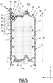
- the inflatable seal 94 has an inverted “U” shape with a horizontal section 95 ( Figure 4 ) forming the bottom of the "U” and two vertical sections 96 forming the branches of the "U".
- Each of the vertical sections 96 is arranged inside the compartment 12 relative to the guide rails 44.
- the guide rails 44 are positioned in a “cold” zone which prevents the guide members 60 from freezing. on the frame 29.
- each of the vertical sections 96 is housed in the cavity 43 of a respective amount 36. Thus, these vertical sections 96 are protected and do not risk being hooked during the loading or unloading of goods through the opening 26.
- Each of said sections 95, 96 is formed by an elastic membrane 97 defining an internal channel 98 adapted to receive pressurized fluid and having a contact surface 100 able to press against the internal face 55 of the apron 30 when the latter is in the position of. closing.
- the elastic membrane 97 is suitable for occupying a rest position, in which the membrane 97, and more particularly the contact surface 100, is away from the closed apron 30, when the internal channel 98 is empty, that is to say. that is to say when it is at a pressure less than or equal to atmospheric pressure, and a deployed position, in which the contact surface 100 is pressed against the interior face 55 of the closed apron 30, when a fluid under pressure, typically air, is injected into the interior channel 98.
- the inflatable seal 94 is in particular continuous, that is to say that the horizontal section 95 is attached to each of the vertical sections 96.
- the membranes 97 of the different sections 95, 96 are advantageously formed by a single continuous membrane. common to said sections 95, 96. This ensures continuous sealing over the entire contour of the door 28.
- the sectional door 28 also comprises a shutter element 110 for closing the window 51 when the apron 30 is in its closed position, and a drive system 112 for moving the apron 30 between its open and closed positions.
- the shutter element 110 comprises in particular a substantially planar flap 114 and a member 116 of articulation of the flap 114 to the end strip 58b defining the first end 56 of the apron 30, for the pivoting of the flap 114 relative to said strip 58b around a substantially transverse articulation axis (not shown).
- the flap 114 is substantially rectangular and has a front edge 115, substantially transverse, and a rear edge 117, substantially transverse. It is elongated in the transverse direction Y.
- the shutter 114 has substantially the same dimensions as the window 51. Thus, when it is placed across the window 51, it closes said window 51.
- the articulation member 116 projects from a face of the flap 114. It has a recess 118, at a distance from the flap 114, in which the hooking member 63 of the end strip 58b is received. Thus, the axis of articulation of the flap 114 to the end strip 58b is spaced from the flap 114.
- the drive system 112 is disposed in the passage 47 defined by the upper cross member 37. It advantageously has a vertical height less than the thickness of the roof e2.
- the drive system 112 comprises in a known manner an own balancing module to counterbalance the weight of the apron 30, and a motorization module suitable for driving the movements of the apron 30 between its open and closed positions.
- the compartment 12 also comprises a device 120 for guiding the apron 30 suitable for guiding the apron 30 in translation in the longitudinal direction X along the upper face 25 of the roof 22 during its movement between its open and closed positions .
- This guide device 120 comprises two guide members 122, each arranged along a respective lateral edge of the roof 22.
- Each guide member 122 comprises a longitudinal slide 124, integral with the flag 22, and a slide 126, attached to the apron 30 and mounted on the slide 124 so as to be movable in translation with respect to the flag 22 in the longitudinal direction X.
- the slide 124 is in particular mounted directly on the upper face 25 of the roof 22. This makes it possible to minimize the height of the structures installed on the roof 22 and therefore the increase in height of the compartment 12 caused by these structures.
- the slide 124 does not project more than 40 mm upwards relative to the upper face 25 of the flag 22.
- the slide 124 is typically formed by a U-shaped rail oriented in the longitudinal direction X and lying on its side, said rail having an opening opening transversely facing a median longitudinal plane (not shown) of the compartment 12.
- the slide 126 advantageously has a height substantially equal to that of the slide 124 and it is partially housed in said slide 124. In this way, the space lost in height between the size limit of the compartment 12 and the lower face of the flag 22 is less than 165 mm.
- the flap 114 is articulated to the slider 126 and forms a connecting part of the slider 126 to the apron 30.
- the flap 114 is articulated to the slider 126 by means of a pivot connection 130 disposed along the front edge 115 of the shutter 114.
- the pivot connection 130 is equipped with a return member (not shown) urging the slide 126 transversely towards the bottom of the slide 124.
- the apron 30 is in its closed position.
- An operator then actuates a command to activate the drive system 112.
- the latter starts up and causes the slats 58a, 58b to rise along the guide rails 44.
- the end strip 58b defining the first end 56 pushes on the shutter 114, which rises partially, releasing the window 51.
- the front edge 115 of the shutter 114 is however prevented from rising by its connection with the slider 124 ; therefore, the flap 114 tilts forward.
- the flap 114 advances towards the front of the compartment 12, along the roof 22, being guided by the guide device 120.
- the shutter 114 frees the pavilion from any obstacles present therein, such as branches or impurities. The release of these obstacles is facilitated by the inclined position of the flap 114.
- the slats 58a, 58b exit one after the other from the uprights 36 and enter the passage 47, where they tilt forward so as to be horizontal once completely out of the passage 47. They are then positioned above the pavilion 22 and rest on the latter via their guide members 60. Thanks to the fact that the guide members 60 include rollers 90, the movement of the slats 58a, 58b along the pavilion 22 can be done without friction. In addition, thanks to the protrusion distance d of the casters 90, the slats 58a, 58b are kept at a sufficient distance from the flag 22 so as not to rub against any impurities present on the flag 22.
- the movement of the apron 30 is thus continued until all the slats 58a, 58b have come out of the uprights 36, the apron 30 then being in the open position and the opening 36 released substantially completely.
- the loading capacity of the compartment 12 is maximized since the apron 30 never encroaches on the interior of the compartment 12.
- the circulation space is also maximized since the uprights 36 do not encroach or encroach very little on the opening 26.
- the manufacturing costs of the compartment are minimized, in particular thanks to the particularly economical production method of the slats 58a, 58b of the apron 30. are then positioned above the flag 22 and rest on the latter via their guide members 60. Thanks to the fact that the guide members 60 include rollers 90, the movement of the slats 58a, 58b along the flag 22 can be done without friction. In addition, thanks to the protruding distance d of the rollers 90, the slats 58a, 58b are kept at a sufficient distance from the flag 22 so as not to rub against any impurities present on the flag 22.
- the movement of the apron 30 is thus continued until all the slats 58a, 58b have come out of the uprights 36, the apron 30 then being in the open position and the opening 36 released substantially completely.
- the loading capacity of the compartment 12 is maximized since the apron 30 never encroaches on the interior of the compartment 12.
- the circulation space is also maximized since the uprights 36 do not encroach or encroach very little on the opening 26.
- the manufacturing costs of the compartment are minimized, in particular thanks to the particularly economical production method of the slats 58a, 58b of the apron 30.
Landscapes
- Engineering & Computer Science (AREA)
- Mechanical Engineering (AREA)
- Fittings On The Vehicle Exterior For Carrying Loads, And Devices For Holding Or Mounting Articles (AREA)
- Body Structure For Vehicles (AREA)
- Refrigerator Housings (AREA)
Priority Applications (1)
| Application Number | Priority Date | Filing Date | Title |
|---|---|---|---|
| PL18195535T PL3456567T3 (pl) | 2017-09-19 | 2018-09-19 | Przedział do transportu towarów z drzwiami segmentowymi i pojazd zawierający taki przedział |
Applications Claiming Priority (1)
| Application Number | Priority Date | Filing Date | Title |
|---|---|---|---|
| FR1758653A FR3071216B1 (fr) | 2017-09-19 | 2017-09-19 | Compartiment de transport de marchandise a porte sectionnelle et vehicule comprenant un tel compartiment |
Publications (2)
| Publication Number | Publication Date |
|---|---|
| EP3456567A1 EP3456567A1 (fr) | 2019-03-20 |
| EP3456567B1 true EP3456567B1 (fr) | 2021-08-11 |
Family
ID=60138607
Family Applications (1)
| Application Number | Title | Priority Date | Filing Date |
|---|---|---|---|
| EP18195535.2A Active EP3456567B1 (fr) | 2017-09-19 | 2018-09-19 | Compartiment de transport de marchandise à porte sectionnelle et véhicule comprenant un tel compartiment |
Country Status (4)
| Country | Link |
|---|---|
| EP (1) | EP3456567B1 (pl) |
| ES (1) | ES2892998T3 (pl) |
| FR (1) | FR3071216B1 (pl) |
| PL (1) | PL3456567T3 (pl) |
Family Cites Families (5)
| Publication number | Priority date | Publication date | Assignee | Title |
|---|---|---|---|---|
| US2250604A (en) * | 1939-10-20 | 1941-07-29 | Kinnear Mfg Co | Rolling door with releasable guide groove |
| GB9214886D0 (en) * | 1992-07-14 | 1992-08-26 | James And Bloom Limited | Sliding shutters and doors |
| FR3014473B1 (fr) * | 2013-12-11 | 2017-05-05 | Jean Chereau Sas | Dispositif de verrouillage/deverrouillage d'un rideau de fermeture d'un compartiment d'un vehicule |
| FR3014373B1 (fr) * | 2013-12-11 | 2016-01-08 | Jean Chereau Sas | Carrosserie pour vehicule de transport de marchandises, munie d'un rideau de fermeture |
| FR3037538B1 (fr) * | 2015-06-18 | 2020-09-18 | Jean Chereau Sas | Rideau segmente pour la fermeture d'un acces a un compartiment d'un vehicule de transport de marchandises |
-
2017
- 2017-09-19 FR FR1758653A patent/FR3071216B1/fr not_active Expired - Fee Related
-
2018
- 2018-09-19 ES ES18195535T patent/ES2892998T3/es active Active
- 2018-09-19 PL PL18195535T patent/PL3456567T3/pl unknown
- 2018-09-19 EP EP18195535.2A patent/EP3456567B1/fr active Active
Non-Patent Citations (1)
| Title |
|---|
| None * |
Also Published As
| Publication number | Publication date |
|---|---|
| PL3456567T3 (pl) | 2022-01-03 |
| FR3071216B1 (fr) | 2019-10-18 |
| EP3456567A1 (fr) | 2019-03-20 |
| ES2892998T3 (es) | 2022-02-07 |
| FR3071216A1 (fr) | 2019-03-22 |
Similar Documents
| Publication | Publication Date | Title |
|---|---|---|
| EP2692561B1 (fr) | Dispositif de fermeture d'un compartiment d'un véhicule de transport de marchandises | |
| EP1930196A1 (fr) | Véhicule monocorps ou bicorps à toit à élément mobile | |
| FR2955077A1 (fr) | Vehicule dote d'un plancher apte a recevoir une batterie et une poutre de renforcement | |
| EP0159206B1 (fr) | Portes d'accès latérales de carrosseries de véhicules, conteneurs, et caisses mobiles | |
| EP0989008B1 (fr) | Véhicule automobile comportant un pavillon escamotable dans une porte transversale arrière | |
| EP3650322B1 (fr) | Carrosserie de véhicule routier de transport de marchandises munie de déflecteurs arrière | |
| FR3071216B1 (fr) | Compartiment de transport de marchandise a porte sectionnelle et vehicule comprenant un tel compartiment | |
| EP3112195B1 (fr) | Rideau segmenté pour la fermeture d'un accès à un compartiment d'un véhicule de transport de marchandises | |
| FR2527256A2 (fr) | Dispositif d'ouverture a surface decouvrable, notamment toit ouvrant pour vehicule automobile | |
| EP3798032B1 (fr) | Porte sectionnelle pour compartiment de transport de marchandise comprenant un joint gonflable, compartiment et véhicule de transport de marchandises associés | |
| FR3128418A1 (fr) | Cloison de compartimentage pour carrosserie frigorifique de véhicule routier de transport de marchandises | |
| EP2025548A1 (fr) | Élément de véhicule comprenant au moins une ossature de cabine de véhicule et véhicule comprenant un tel élément de véhicule | |
| FR3150747A1 (fr) | Carrosserie frigorifique de véhicule routier de transport de marchandises équipée d’une cloison de compartimentage | |
| EP3853053B1 (fr) | Carrosserie, notamment de véhicule routier ou ferroviaire | |
| FR3101844A1 (fr) | Vehicule comportant un faux plancher de coffre verrouillable | |
| FR3111103A1 (fr) | Cloison de compartimentage pour carrosserie frigorifique de véhicule routier de transport de marchandises, et procédé de fabrication associé | |
| FR2876076A1 (fr) | Structure de coffre de vehicule automobile et vehicule automobile comportant une telle structure | |
| FR3093680A1 (fr) | Dispositif de portage adaptatif d’au moins un objet au travers d’un élément de carrosserie d’un véhicule | |
| FR2865163A1 (fr) | Vehicule a toit decouvrable et hayon arriere | |
| EP4477435A1 (fr) | Dispositif de gestion de contact pour véhicule automobile à portes antagonistes | |
| EP0461008B1 (fr) | Toit ouvrant pour véhicule automobile | |
| FR3154947A1 (fr) | Dispositif d’accès pour un véhicule automobile avec des portes antagonistes. | |
| EP1806255B1 (fr) | Ensemble de support d'un panneau de coffre de véhicule automobile et véhicule automobile équipé d'un tel ensemble de support | |
| EP4737218A1 (fr) | Structure arrière de véhicule automobile | |
| FR3152823A1 (fr) | Ouvrant coulissant motorisé d’un véhicule. |
Legal Events
| Date | Code | Title | Description |
|---|---|---|---|
| PUAI | Public reference made under article 153(3) epc to a published international application that has entered the european phase |
Free format text: ORIGINAL CODE: 0009012 |
|
| STAA | Information on the status of an ep patent application or granted ep patent |
Free format text: STATUS: THE APPLICATION HAS BEEN PUBLISHED |
|
| AK | Designated contracting states |
Kind code of ref document: A1 Designated state(s): AL AT BE BG CH CY CZ DE DK EE ES FI FR GB GR HR HU IE IS IT LI LT LU LV MC MK MT NL NO PL PT RO RS SE SI SK SM TR |
|
| AX | Request for extension of the european patent |
Extension state: BA ME |
|
| STAA | Information on the status of an ep patent application or granted ep patent |
Free format text: STATUS: REQUEST FOR EXAMINATION WAS MADE |
|
| 17P | Request for examination filed |
Effective date: 20190822 |
|
| RBV | Designated contracting states (corrected) |
Designated state(s): AL AT BE BG CH CY CZ DE DK EE ES FI FR GB GR HR HU IE IS IT LI LT LU LV MC MK MT NL NO PL PT RO RS SE SI SK SM TR |
|
| STAA | Information on the status of an ep patent application or granted ep patent |
Free format text: STATUS: EXAMINATION IS IN PROGRESS |
|
| 17Q | First examination report despatched |
Effective date: 20200707 |
|
| GRAP | Despatch of communication of intention to grant a patent |
Free format text: ORIGINAL CODE: EPIDOSNIGR1 |
|
| STAA | Information on the status of an ep patent application or granted ep patent |
Free format text: STATUS: GRANT OF PATENT IS INTENDED |
|
| INTG | Intention to grant announced |
Effective date: 20210323 |
|
| GRAS | Grant fee paid |
Free format text: ORIGINAL CODE: EPIDOSNIGR3 |
|
| GRAA | (expected) grant |
Free format text: ORIGINAL CODE: 0009210 |
|
| STAA | Information on the status of an ep patent application or granted ep patent |
Free format text: STATUS: THE PATENT HAS BEEN GRANTED |
|
| AK | Designated contracting states |
Kind code of ref document: B1 Designated state(s): AL AT BE BG CH CY CZ DE DK EE ES FI FR GB GR HR HU IE IS IT LI LT LU LV MC MK MT NL NO PL PT RO RS SE SI SK SM TR |
|
| REG | Reference to a national code |
Ref country code: CH Ref legal event code: EP |
|
| REG | Reference to a national code |
Ref country code: DE Ref legal event code: R096 Ref document number: 602018021523 Country of ref document: DE |
|
| REG | Reference to a national code |
Ref country code: IE Ref legal event code: FG4D Free format text: LANGUAGE OF EP DOCUMENT: FRENCH Ref country code: AT Ref legal event code: REF Ref document number: 1419032 Country of ref document: AT Kind code of ref document: T Effective date: 20210915 |
|
| REG | Reference to a national code |
Ref country code: NL Ref legal event code: FP |
|
| REG | Reference to a national code |
Ref country code: LT Ref legal event code: MG9D |
|
| REG | Reference to a national code |
Ref country code: AT Ref legal event code: MK05 Ref document number: 1419032 Country of ref document: AT Kind code of ref document: T Effective date: 20210811 |
|
| PG25 | Lapsed in a contracting state [announced via postgrant information from national office to epo] |
Ref country code: FI Free format text: LAPSE BECAUSE OF FAILURE TO SUBMIT A TRANSLATION OF THE DESCRIPTION OR TO PAY THE FEE WITHIN THE PRESCRIBED TIME-LIMIT Effective date: 20210811 Ref country code: HR Free format text: LAPSE BECAUSE OF FAILURE TO SUBMIT A TRANSLATION OF THE DESCRIPTION OR TO PAY THE FEE WITHIN THE PRESCRIBED TIME-LIMIT Effective date: 20210811 Ref country code: SE Free format text: LAPSE BECAUSE OF FAILURE TO SUBMIT A TRANSLATION OF THE DESCRIPTION OR TO PAY THE FEE WITHIN THE PRESCRIBED TIME-LIMIT Effective date: 20210811 Ref country code: RS Free format text: LAPSE BECAUSE OF FAILURE TO SUBMIT A TRANSLATION OF THE DESCRIPTION OR TO PAY THE FEE WITHIN THE PRESCRIBED TIME-LIMIT Effective date: 20210811 Ref country code: AT Free format text: LAPSE BECAUSE OF FAILURE TO SUBMIT A TRANSLATION OF THE DESCRIPTION OR TO PAY THE FEE WITHIN THE PRESCRIBED TIME-LIMIT Effective date: 20210811 Ref country code: BG Free format text: LAPSE BECAUSE OF FAILURE TO SUBMIT A TRANSLATION OF THE DESCRIPTION OR TO PAY THE FEE WITHIN THE PRESCRIBED TIME-LIMIT Effective date: 20211111 Ref country code: LT Free format text: LAPSE BECAUSE OF FAILURE TO SUBMIT A TRANSLATION OF THE DESCRIPTION OR TO PAY THE FEE WITHIN THE PRESCRIBED TIME-LIMIT Effective date: 20210811 Ref country code: NO Free format text: LAPSE BECAUSE OF FAILURE TO SUBMIT A TRANSLATION OF THE DESCRIPTION OR TO PAY THE FEE WITHIN THE PRESCRIBED TIME-LIMIT Effective date: 20211111 Ref country code: PT Free format text: LAPSE BECAUSE OF FAILURE TO SUBMIT A TRANSLATION OF THE DESCRIPTION OR TO PAY THE FEE WITHIN THE PRESCRIBED TIME-LIMIT Effective date: 20211213 |
|
| REG | Reference to a national code |
Ref country code: ES Ref legal event code: FG2A Ref document number: 2892998 Country of ref document: ES Kind code of ref document: T3 Effective date: 20220207 |
|
| PG25 | Lapsed in a contracting state [announced via postgrant information from national office to epo] |
Ref country code: LV Free format text: LAPSE BECAUSE OF FAILURE TO SUBMIT A TRANSLATION OF THE DESCRIPTION OR TO PAY THE FEE WITHIN THE PRESCRIBED TIME-LIMIT Effective date: 20210811 Ref country code: GR Free format text: LAPSE BECAUSE OF FAILURE TO SUBMIT A TRANSLATION OF THE DESCRIPTION OR TO PAY THE FEE WITHIN THE PRESCRIBED TIME-LIMIT Effective date: 20211112 |
|
| PG25 | Lapsed in a contracting state [announced via postgrant information from national office to epo] |
Ref country code: DK Free format text: LAPSE BECAUSE OF FAILURE TO SUBMIT A TRANSLATION OF THE DESCRIPTION OR TO PAY THE FEE WITHIN THE PRESCRIBED TIME-LIMIT Effective date: 20210811 |
|
| REG | Reference to a national code |
Ref country code: CH Ref legal event code: PL |
|
| REG | Reference to a national code |
Ref country code: DE Ref legal event code: R097 Ref document number: 602018021523 Country of ref document: DE |
|
| PG25 | Lapsed in a contracting state [announced via postgrant information from national office to epo] |
Ref country code: SM Free format text: LAPSE BECAUSE OF FAILURE TO SUBMIT A TRANSLATION OF THE DESCRIPTION OR TO PAY THE FEE WITHIN THE PRESCRIBED TIME-LIMIT Effective date: 20210811 Ref country code: SK Free format text: LAPSE BECAUSE OF FAILURE TO SUBMIT A TRANSLATION OF THE DESCRIPTION OR TO PAY THE FEE WITHIN THE PRESCRIBED TIME-LIMIT Effective date: 20210811 Ref country code: RO Free format text: LAPSE BECAUSE OF FAILURE TO SUBMIT A TRANSLATION OF THE DESCRIPTION OR TO PAY THE FEE WITHIN THE PRESCRIBED TIME-LIMIT Effective date: 20210811 Ref country code: MC Free format text: LAPSE BECAUSE OF FAILURE TO SUBMIT A TRANSLATION OF THE DESCRIPTION OR TO PAY THE FEE WITHIN THE PRESCRIBED TIME-LIMIT Effective date: 20210811 Ref country code: EE Free format text: LAPSE BECAUSE OF FAILURE TO SUBMIT A TRANSLATION OF THE DESCRIPTION OR TO PAY THE FEE WITHIN THE PRESCRIBED TIME-LIMIT Effective date: 20210811 Ref country code: CZ Free format text: LAPSE BECAUSE OF FAILURE TO SUBMIT A TRANSLATION OF THE DESCRIPTION OR TO PAY THE FEE WITHIN THE PRESCRIBED TIME-LIMIT Effective date: 20210811 Ref country code: AL Free format text: LAPSE BECAUSE OF FAILURE TO SUBMIT A TRANSLATION OF THE DESCRIPTION OR TO PAY THE FEE WITHIN THE PRESCRIBED TIME-LIMIT Effective date: 20210811 |
|
| PLBE | No opposition filed within time limit |
Free format text: ORIGINAL CODE: 0009261 |
|
| STAA | Information on the status of an ep patent application or granted ep patent |
Free format text: STATUS: NO OPPOSITION FILED WITHIN TIME LIMIT |
|
| 26N | No opposition filed |
Effective date: 20220512 |
|
| PG25 | Lapsed in a contracting state [announced via postgrant information from national office to epo] |
Ref country code: LU Free format text: LAPSE BECAUSE OF NON-PAYMENT OF DUE FEES Effective date: 20210919 Ref country code: IE Free format text: LAPSE BECAUSE OF NON-PAYMENT OF DUE FEES Effective date: 20210919 |
|
| PG25 | Lapsed in a contracting state [announced via postgrant information from national office to epo] |
Ref country code: SI Free format text: LAPSE BECAUSE OF FAILURE TO SUBMIT A TRANSLATION OF THE DESCRIPTION OR TO PAY THE FEE WITHIN THE PRESCRIBED TIME-LIMIT Effective date: 20210811 Ref country code: LI Free format text: LAPSE BECAUSE OF NON-PAYMENT OF DUE FEES Effective date: 20210930 Ref country code: CH Free format text: LAPSE BECAUSE OF NON-PAYMENT OF DUE FEES Effective date: 20210930 |
|
| PG25 | Lapsed in a contracting state [announced via postgrant information from national office to epo] |
Ref country code: CY Free format text: LAPSE BECAUSE OF FAILURE TO SUBMIT A TRANSLATION OF THE DESCRIPTION OR TO PAY THE FEE WITHIN THE PRESCRIBED TIME-LIMIT Effective date: 20210811 |
|
| PG25 | Lapsed in a contracting state [announced via postgrant information from national office to epo] |
Ref country code: HU Free format text: LAPSE BECAUSE OF FAILURE TO SUBMIT A TRANSLATION OF THE DESCRIPTION OR TO PAY THE FEE WITHIN THE PRESCRIBED TIME-LIMIT; INVALID AB INITIO Effective date: 20180919 |
|
| PG25 | Lapsed in a contracting state [announced via postgrant information from national office to epo] |
Ref country code: MK Free format text: LAPSE BECAUSE OF FAILURE TO SUBMIT A TRANSLATION OF THE DESCRIPTION OR TO PAY THE FEE WITHIN THE PRESCRIBED TIME-LIMIT Effective date: 20210811 |
|
| PG25 | Lapsed in a contracting state [announced via postgrant information from national office to epo] |
Ref country code: MT Free format text: LAPSE BECAUSE OF FAILURE TO SUBMIT A TRANSLATION OF THE DESCRIPTION OR TO PAY THE FEE WITHIN THE PRESCRIBED TIME-LIMIT Effective date: 20210811 |
|
| PGFP | Annual fee paid to national office [announced via postgrant information from national office to epo] |
Ref country code: DE Payment date: 20250916 Year of fee payment: 8 |
|
| PGFP | Annual fee paid to national office [announced via postgrant information from national office to epo] |
Ref country code: NL Payment date: 20250909 Year of fee payment: 8 Ref country code: PL Payment date: 20250825 Year of fee payment: 8 Ref country code: IT Payment date: 20250909 Year of fee payment: 8 |
|
| PGFP | Annual fee paid to national office [announced via postgrant information from national office to epo] |
Ref country code: BE Payment date: 20250919 Year of fee payment: 8 Ref country code: GB Payment date: 20250919 Year of fee payment: 8 |
|
| PGFP | Annual fee paid to national office [announced via postgrant information from national office to epo] |
Ref country code: FR Payment date: 20250812 Year of fee payment: 8 |
|
| PG25 | Lapsed in a contracting state [announced via postgrant information from national office to epo] |
Ref country code: TR Free format text: LAPSE BECAUSE OF FAILURE TO SUBMIT A TRANSLATION OF THE DESCRIPTION OR TO PAY THE FEE WITHIN THE PRESCRIBED TIME-LIMIT Effective date: 20210811 |
|
| PGFP | Annual fee paid to national office [announced via postgrant information from national office to epo] |
Ref country code: ES Payment date: 20251015 Year of fee payment: 8 |