EP3456459A1 - Method and apparatus for auto-aligning of a process gas jet nozzle and laser machining beam - Google Patents
Method and apparatus for auto-aligning of a process gas jet nozzle and laser machining beam Download PDFInfo
- Publication number
- EP3456459A1 EP3456459A1 EP18195416.5A EP18195416A EP3456459A1 EP 3456459 A1 EP3456459 A1 EP 3456459A1 EP 18195416 A EP18195416 A EP 18195416A EP 3456459 A1 EP3456459 A1 EP 3456459A1
- Authority
- EP
- European Patent Office
- Prior art keywords
- axis
- gas jet
- laser
- collar
- actuator
- Prior art date
- Legal status (The legal status is an assumption and is not a legal conclusion. Google has not performed a legal analysis and makes no representation as to the accuracy of the status listed.)
- Granted
Links
Images



Classifications
-
- B—PERFORMING OPERATIONS; TRANSPORTING
- B23—MACHINE TOOLS; METAL-WORKING NOT OTHERWISE PROVIDED FOR
- B23K—SOLDERING OR UNSOLDERING; WELDING; CLADDING OR PLATING BY SOLDERING OR WELDING; CUTTING BY APPLYING HEAT LOCALLY, e.g. FLAME CUTTING; WORKING BY LASER BEAM
- B23K26/00—Working by laser beam, e.g. welding, cutting or boring
- B23K26/14—Working by laser beam, e.g. welding, cutting or boring using a fluid stream, e.g. a jet of gas, in conjunction with the laser beam; Nozzles therefor
- B23K26/1435—Working by laser beam, e.g. welding, cutting or boring using a fluid stream, e.g. a jet of gas, in conjunction with the laser beam; Nozzles therefor involving specially adapted flow-control means
-
- B—PERFORMING OPERATIONS; TRANSPORTING
- B23—MACHINE TOOLS; METAL-WORKING NOT OTHERWISE PROVIDED FOR
- B23K—SOLDERING OR UNSOLDERING; WELDING; CLADDING OR PLATING BY SOLDERING OR WELDING; CUTTING BY APPLYING HEAT LOCALLY, e.g. FLAME CUTTING; WORKING BY LASER BEAM
- B23K26/00—Working by laser beam, e.g. welding, cutting or boring
- B23K26/14—Working by laser beam, e.g. welding, cutting or boring using a fluid stream, e.g. a jet of gas, in conjunction with the laser beam; Nozzles therefor
- B23K26/1462—Nozzles; Features related to nozzles
- B23K26/1494—Maintenance of nozzles
-
- B—PERFORMING OPERATIONS; TRANSPORTING
- B23—MACHINE TOOLS; METAL-WORKING NOT OTHERWISE PROVIDED FOR
- B23K—SOLDERING OR UNSOLDERING; WELDING; CLADDING OR PLATING BY SOLDERING OR WELDING; CUTTING BY APPLYING HEAT LOCALLY, e.g. FLAME CUTTING; WORKING BY LASER BEAM
- B23K26/00—Working by laser beam, e.g. welding, cutting or boring
- B23K26/02—Positioning or observing the workpiece, e.g. with respect to the point of impact; Aligning, aiming or focusing the laser beam
- B23K26/035—Aligning the laser beam
-
- B—PERFORMING OPERATIONS; TRANSPORTING
- B23—MACHINE TOOLS; METAL-WORKING NOT OTHERWISE PROVIDED FOR
- B23K—SOLDERING OR UNSOLDERING; WELDING; CLADDING OR PLATING BY SOLDERING OR WELDING; CUTTING BY APPLYING HEAT LOCALLY, e.g. FLAME CUTTING; WORKING BY LASER BEAM
- B23K26/00—Working by laser beam, e.g. welding, cutting or boring
- B23K26/02—Positioning or observing the workpiece, e.g. with respect to the point of impact; Aligning, aiming or focusing the laser beam
- B23K26/04—Automatically aligning, aiming or focusing the laser beam, e.g. using the back-scattered light
- B23K26/042—Automatically aligning the laser beam
-
- B—PERFORMING OPERATIONS; TRANSPORTING
- B23—MACHINE TOOLS; METAL-WORKING NOT OTHERWISE PROVIDED FOR
- B23K—SOLDERING OR UNSOLDERING; WELDING; CLADDING OR PLATING BY SOLDERING OR WELDING; CUTTING BY APPLYING HEAT LOCALLY, e.g. FLAME CUTTING; WORKING BY LASER BEAM
- B23K26/00—Working by laser beam, e.g. welding, cutting or boring
- B23K26/14—Working by laser beam, e.g. welding, cutting or boring using a fluid stream, e.g. a jet of gas, in conjunction with the laser beam; Nozzles therefor
- B23K26/142—Working by laser beam, e.g. welding, cutting or boring using a fluid stream, e.g. a jet of gas, in conjunction with the laser beam; Nozzles therefor for the removal of by-products
-
- B—PERFORMING OPERATIONS; TRANSPORTING
- B23—MACHINE TOOLS; METAL-WORKING NOT OTHERWISE PROVIDED FOR
- B23K—SOLDERING OR UNSOLDERING; WELDING; CLADDING OR PLATING BY SOLDERING OR WELDING; CUTTING BY APPLYING HEAT LOCALLY, e.g. FLAME CUTTING; WORKING BY LASER BEAM
- B23K26/00—Working by laser beam, e.g. welding, cutting or boring
- B23K26/14—Working by laser beam, e.g. welding, cutting or boring using a fluid stream, e.g. a jet of gas, in conjunction with the laser beam; Nozzles therefor
- B23K26/1462—Nozzles; Features related to nozzles
-
- B—PERFORMING OPERATIONS; TRANSPORTING
- B23—MACHINE TOOLS; METAL-WORKING NOT OTHERWISE PROVIDED FOR
- B23K—SOLDERING OR UNSOLDERING; WELDING; CLADDING OR PLATING BY SOLDERING OR WELDING; CUTTING BY APPLYING HEAT LOCALLY, e.g. FLAME CUTTING; WORKING BY LASER BEAM
- B23K26/00—Working by laser beam, e.g. welding, cutting or boring
- B23K26/14—Working by laser beam, e.g. welding, cutting or boring using a fluid stream, e.g. a jet of gas, in conjunction with the laser beam; Nozzles therefor
- B23K26/1462—Nozzles; Features related to nozzles
- B23K26/1482—Detachable nozzles, e.g. exchangeable or provided with breakaway lines
-
- B—PERFORMING OPERATIONS; TRANSPORTING
- B23—MACHINE TOOLS; METAL-WORKING NOT OTHERWISE PROVIDED FOR
- B23K—SOLDERING OR UNSOLDERING; WELDING; CLADDING OR PLATING BY SOLDERING OR WELDING; CUTTING BY APPLYING HEAT LOCALLY, e.g. FLAME CUTTING; WORKING BY LASER BEAM
- B23K26/00—Working by laser beam, e.g. welding, cutting or boring
- B23K26/08—Devices involving relative movement between laser beam and workpiece
- B23K26/0869—Devices involving movement of the laser head in at least one axial direction
- B23K26/0876—Devices involving movement of the laser head in at least one axial direction in at least two axial directions
- B23K26/0884—Devices involving movement of the laser head in at least one axial direction in at least two axial directions in at least three axial directions, e.g. manipulators, robots
-
- B—PERFORMING OPERATIONS; TRANSPORTING
- B23—MACHINE TOOLS; METAL-WORKING NOT OTHERWISE PROVIDED FOR
- B23K—SOLDERING OR UNSOLDERING; WELDING; CLADDING OR PLATING BY SOLDERING OR WELDING; CUTTING BY APPLYING HEAT LOCALLY, e.g. FLAME CUTTING; WORKING BY LASER BEAM
- B23K26/00—Working by laser beam, e.g. welding, cutting or boring
- B23K26/70—Auxiliary operations or equipment
Definitions
- the present disclosure relates to adjusting the relative positions of the axes of a laser machining beam and a process gas jet of a laser machining system.
- a process gas jet is directed at the laser machining point.
- oxygen or inert gases such as nitrogen or argon, are used as process gases.
- Molten material that is formed in the course of the cutting process is intended to be blown away from the kerf by the process gases.
- a desired relative position of the laser machining beam relative to the process gas jet is required.
- optimum machining results are achieved when an axis of the laser beam and an axis of the gas jet coincide.
- An adjustment collar for a laser machine tool can include an outer housing; an inner collar; a first actuator between the outer housing and the inner collar, the first actuator operable to move the inner collar with respect to the outer housing along an X-axis; and a second actuator between the outer housing and the inner collar, the second actuator operable to move the inner collar with respect to the outer housing along a Y-axis.
- a further embodiment of any of the embodiments of the present disclosure may include that the first actuator and the second actuator are piezoelectric motors.
- a further embodiment of any of the embodiments of the present disclosure may include that the outer housing is mountable to a laser cutting head.
- a further embodiment of any of the embodiments of the present disclosure may include that the inner collar is mountable to a process gas jet nozzle.
- a further embodiment of any of the embodiments of the present disclosure may include a controller in communication with the first actuator and the second actuator.
- a laser machine tool can include a laser that defines a laser beam axis; a process gas jet nozzle that defines a gas jet axis; an adjustment collar mounted with respect to the laser and the process gas jet nozzle; and a controller in communication with the adjustment collar to move the process gas jet nozzle with respect to the laser to position the laser beam axis with respect to the gas jet axis.
- a further embodiment of any of the embodiments of the present disclosure may include an outer housing of the adjustment collar, the outer housing mounted to a laser cutting head that contains the laser.
- a further embodiment of any of the embodiments of the present disclosure may include an inner collar of the adjustment collar mounted to the process gas jet nozzle.
- a further embodiment of any of the embodiments of the present disclosure may include a first actuator between the outer housing and the inner collar, the first actuator operable to move the inner collar with respect to the outer housing in an X-axis; and a second actuator between the outer housing and the inner collar, the second actuator operable to move the inner collar with respect to the outer housing in a Y-axis.
- a further embodiment of any of the embodiments of the present disclosure may include, that the first actuator and the second actuator are piezoelectric motors.
- a method for adjusting an adjusting collar to move a process gas jet nozzle with respect to a laser cutting head to align a gas jet axis with respect to a laser beam axis can include adjusting a first actuator between an outer housing of an adjusting collar mounted to a laser cutting head and an inner collar of the adjusting collar, the first actuator operable to move the inner collar with respect to the outer housing along an X-axis; and adjusting a second actuator between the outer housing of the adjusting collar mounted to the laser cutting head and the inner collar of the adjusting collar, the second actuator between the outer housing and the inner collar, the second actuator operable to move the inner collar with respect to the outer housing along a Y-axis.
- a further embodiment of any of the embodiments of the present disclosure may include determining a location of the laser beam axis based on a positon of the laser cutting head; cutting a hole in a sacrificial workpiece with the laser of the laser cutting head; measuring the hole with a process gas jet nozzle mounted to the laser cutting head to determine a location of a gas jet axis at a center of the hole; comparing the location of the gas jet axis with respect to the location of the laser beam axis; and adjusting the adjusting collar to move the process gas jet nozzle with respect to the laser cutting head to align the gas jet axis with respect to the laser beam axis.
- a further embodiment of any of the embodiments of the present disclosure may include that determining the location of the laser beam axis is presumed to be a central axis of the laser cutting head.
- a further embodiment of any of the embodiments of the present disclosure may include determining a capacitance with the process gas jet nozzle to find the edge of the hole.
- a further embodiment of any of the embodiments of the present disclosure may include moving the process gas jet nozzle along an X- axis.
- a further embodiment of any of the embodiments of the present disclosure may include moving the process gas jet nozzle along an Y-axis.
- a further embodiment of any of the embodiments of the present disclosure may include automatically adjusting the adjusting collar in response to a controller to align the first axis location to the center of the hole.
- a further embodiment of any of the embodiments of the present disclosure may include that to align the first axis location to the center of the hole aligns a gas jet axis with respect to a laser beam axis.
- a further embodiment of any of the embodiments of the present disclosure may include that to align the first axis location to the center of the hole aligns a gas jet axis with respect to a laser beam axis such that the axes are coaxial.
- FIG. 1 schematically illustrates a laser machine tool 20 in the form of a laser cutting machine.
- the laser machine tool 20 generally includes a machine bed 22, over which a first joint 24 is movably guided in a first axial direction.
- the first joint 24 supports a second joint 26 with a laser cutting head 28. Jointly with the second joint 26, the laser cutting head 28 is movable in a second axial direction relative the first joint 24. Furthermore, the laser cutting head 28 is movable relative to the second joint 26 in a third axial direction. Beneath the laser cutting head 28, a workpiece W is arranged on the machine bed 22.
- the laser cutting head 28 includes a laser 30 that generates a laser beam along a laser beam axis 32.
- the laser 30 is contained within the laser cutting head 28 and may be directed through optics 34 to direct the laser beam through a process gas jet nozzle 50.
- the mobility of the first joint 24 and the second joint 26 permits a desired point on the workpiece W to be machined with the laser cutting beam.
- the mobility of the laser cutting head 28 in the Z-direction is used to adjust the focal position of the laser cutting beam in the direction transverse to the workpiece W.
- the motor drive 44 may be operable to move the laser cutting head 28 in a coordinate system.
- a 6-axis laser machine tool 20 has the ability to interpolate either linearly for X, Y, Z, or rotationally A, B, and U.
- an R axis may be defined for each orientation of the coordinate systems when viewed isometrically.
- the R axis is an artificial axis created by the machine software that can move the laser cutting head 28 parallel along a vector created normal to the workpiece W, however nomenclature often varies by machine.
- the operation of the laser machine tool 20 may also be integrated into the controller 46 to position the laser 30 and the associated process gas jet nozzle 50.
- the controller 46 is operable to continually determine the position of the laser cutting head 28 within the coordinate system.
- the process gas jet nozzle 50 is mounted to the laser cutting head 28.
- a process gas jet for example nitrogen, is directed from the process gas jet nozzle 50 to blow the molten metal formed at the machining point of the laser beam from the resulting kerf.
- the laser beam axis 32 from the laser 30, and a gas jet axis 52 of the process gas jet nozzle 50 coincide in a coaxial manner. That is, the laser beam is directed along the gas jet axis 52 of the process gas jet nozzle 50.
- the laser cutting beam axis 32 and the process gas jet axis 52 may move out of alignment.
- an adjustment collar 60 is mounted between the laser cutting head 28 and the process gas jet nozzle 50 to adjust the laser beam axis 32 and the gas jet axis 52.
- the controller 46 is operable to determine the position of the laser cutting head 28 within the coordinate system.
- the process gas jet nozzle 50 is also utilized as a sensor for the controller 46 as the process gas jet nozzle 50 measures capacitance at a tip thereof to, for example, identify an edge of a hole in the workpiece W as the capacitance changes at the edge.
- Other methods for determining misalignment exist such as via a bore camera through the process gas jet nozzle 50.
- the adjustment collar 60 generally includes an outer housing 62 mounted to the laser cutting head 28 and an inner collar 64 mounted to the process gas jet nozzle 50.
- An actuator 66 in the X-axis and an actuator 68 in the Y-axis are mounted between the outer housing 62 inner collar 64 to position the inner collar 64 with respect to the outer housing 62.
- the actuators 66, 68 may be piezoelectric motors that have an accuracy of, in one example, 0.8 nanometers.
- the actuators 66, 68 have 130 kHz drive frequency that provides speeds of 250 mm/s, and a dynamic resolution of less than 1.0 micron.
- the actuators 66, 68 are in communication with the controller 46.
- a method 100 for positioning the laser beam and an associated process gas jet of the laser machine tool 20 includes mounting (102) a sacrificial workpiece W in the laser machine tool 20.
- an operator positions (104) the laser cutting head 28 over the sacrificial workpiece W.
- the operator then loads (106) a subroutine for aligning the laser beam axis 32 with respect to the gas jet axis 52 into the controller 46.
- the subroutine may be an algorithm or other machine program that operates on the controller 46.
- the algorithm activates the laser 30 of the laser cutting head 28 to cut (110) a hole "H" in the sacrificial workpiece W.
- the hole "H” that is cut may be of an arbitrary size, such as 0.5 inches (12.7 mm) in diameter.
- the laser beam at the focal point on the workpiece W is, for example, 0.005 inches (0.127 mm) in diameter.
- the exit of the process gas jet nozzle 50 is typically 0.060 - 0.080 inches (1.5 - 2.0 mm) in diameter.
- the process gas jet nozzle 50 initial positon (the initial gas jet axis 52 location) is the initial laser beam axis 32 location if coaxially aligned.
- the laser 30, and thus the laser beam axis 32 may be misaligned with the gas jet axis 52 and thus the laser 30 is not coaxial with the process gas jet nozzle 50. This offset is determined and corrected by the method 100.
- the controller 46 then utilizes the process gas jet nozzle 50 to scan (112) the hole “H” to determine an edge (114) of the hole.
- the hole “H” may be scanned along the X-axis and the Y-axis such that an edge is sensed by a change in capacitance sensed at the process gas jet nozzle 50. Since the hole is circular, only a few points on the edge need be determined to identify the hole location, diameter, and thus the center thereof.
- the controller 46 then uses the edge location to calculate where a center (116) of the hole "H” is located in the sacrificial workpiece W.
- the difference between the laser beam axis 32 with respect to the gas jet axis 52 is determined because the laser 30 cuts the hole "H" without knowing the center as the center is the initial gas jet axis 52 is obtained from the original position of the laser cutting head 28, but the process gas jet nozzle 50 measures the hole "H” such that any discrepancy therebetween is identified. That is, the laser cutting head 28 original position is known, but the process gas jet nozzle 50 may not be coaxial with the laser 30.
- the offset between the laser beam axis 32 and the gas jet axis 52 is then determined (118) by the controller 46.
- the determined offset of the laser beam axis 32 from the gas jet axis 52 forms the basis for a correction of the relative position of the two axes 32, 52 in a closed loop manner through the adjustment collar 60.
- the algorithm then utilizes the offset between the laser beam axis 32 with respect to the gas jet axis 52 in the X and Y axes and communicates the location to the controller 46.
- the algorithm then adjusts (120) the actuators 66, 68 to align the laser beam axis 32 and the gas jet axis 52 to compensate for the offset and bring the axes into a coaxial relationship.
- the actuators 66, 68 provide accurate, precise and repeatable alignment of the laser beam axis 32 and the gas jet axis 52 with minimal operator intervention and facilitate increased alignment opportunities during manufacturing.
- the method 100 essentially removes operator intervention and potential error with respect to physically aligning the laser machine tool process gas jet nozzle and the laser. This facilitates replacement of the current style set screw aperture that exists with an electronically controlled aperture of the same form factor.
- the piezoelectric motors move accurately in the X-Y plane using feedback from the algorithm such that the laser beam axis 32 and the gas jet axis 52 automatically align.
- the adjustment collar 60 does not increase the physical size of the laser cutting head 28 and are readily retrofitted.
Landscapes
- Physics & Mathematics (AREA)
- Optics & Photonics (AREA)
- Engineering & Computer Science (AREA)
- Plasma & Fusion (AREA)
- Mechanical Engineering (AREA)
- Laser Beam Processing (AREA)
Abstract
Description
- The present disclosure relates to adjusting the relative positions of the axes of a laser machining beam and a process gas jet of a laser machining system.
- In various types of laser machines, a process gas jet is directed at the laser machining point. In laser cutting, oxygen or inert gases such as nitrogen or argon, are used as process gases. Molten material that is formed in the course of the cutting process is intended to be blown away from the kerf by the process gases. In these processes, a desired relative position of the laser machining beam relative to the process gas jet is required. In laser cutting, optimum machining results are achieved when an axis of the laser beam and an axis of the gas jet coincide. When changing nozzles, during an impact of the nozzle, or just over time, the desired relative positioning of the laser beam axis and the gas jet axis may become misaligned.
- An adjustment collar for a laser machine tool according to one disclosed non-limiting embodiment of the present disclosure can include an outer housing; an inner collar; a first actuator between the outer housing and the inner collar, the first actuator operable to move the inner collar with respect to the outer housing along an X-axis; and a second actuator between the outer housing and the inner collar, the second actuator operable to move the inner collar with respect to the outer housing along a Y-axis.
- A further embodiment of any of the embodiments of the present disclosure may include that the first actuator and the second actuator are piezoelectric motors.
- A further embodiment of any of the embodiments of the present disclosure may include that the outer housing is mountable to a laser cutting head.
- A further embodiment of any of the embodiments of the present disclosure may include that the inner collar is mountable to a process gas jet nozzle.
- A further embodiment of any of the embodiments of the present disclosure may include a controller in communication with the first actuator and the second actuator.
- A laser machine tool according to one disclosed non-limiting embodiment of the present disclosure can include a laser that defines a laser beam axis; a process gas jet nozzle that defines a gas jet axis; an adjustment collar mounted with respect to the laser and the process gas jet nozzle; and a controller in communication with the adjustment collar to move the process gas jet nozzle with respect to the laser to position the laser beam axis with respect to the gas jet axis.
- A further embodiment of any of the embodiments of the present disclosure may include an outer housing of the adjustment collar, the outer housing mounted to a laser cutting head that contains the laser.
- A further embodiment of any of the embodiments of the present disclosure may include an inner collar of the adjustment collar mounted to the process gas jet nozzle.
- A further embodiment of any of the embodiments of the present disclosure may include a first actuator between the outer housing and the inner collar, the first actuator operable to move the inner collar with respect to the outer housing in an X-axis; and a second actuator between the outer housing and the inner collar, the second actuator operable to move the inner collar with respect to the outer housing in a Y-axis.
- A further embodiment of any of the embodiments of the present disclosure may include, that the first actuator and the second actuator are piezoelectric motors.
- A method for adjusting an adjusting collar to move a process gas jet nozzle with respect to a laser cutting head to align a gas jet axis with respect to a laser beam axis, the method according to one disclosed non-limiting embodiment of the present disclosure can include adjusting a first actuator between an outer housing of an adjusting collar mounted to a laser cutting head and an inner collar of the adjusting collar, the first actuator operable to move the inner collar with respect to the outer housing along an X-axis; and adjusting a second actuator between the outer housing of the adjusting collar mounted to the laser cutting head and the inner collar of the adjusting collar, the second actuator between the outer housing and the inner collar, the second actuator operable to move the inner collar with respect to the outer housing along a Y-axis.
- A further embodiment of any of the embodiments of the present disclosure may include determining a location of the laser beam axis based on a positon of the laser cutting head; cutting a hole in a sacrificial workpiece with the laser of the laser cutting head; measuring the hole with a process gas jet nozzle mounted to the laser cutting head to determine a location of a gas jet axis at a center of the hole; comparing the location of the gas jet axis with respect to the location of the laser beam axis; and adjusting the adjusting collar to move the process gas jet nozzle with respect to the laser cutting head to align the gas jet axis with respect to the laser beam axis.
- A further embodiment of any of the embodiments of the present disclosure may include that determining the location of the laser beam axis is presumed to be a central axis of the laser cutting head.
- A further embodiment of any of the embodiments of the present disclosure may include determining a capacitance with the process gas jet nozzle to find the edge of the hole.
- A further embodiment of any of the embodiments of the present disclosure may include moving the process gas jet nozzle along an X- axis.
- A further embodiment of any of the embodiments of the present disclosure may include moving the process gas jet nozzle along an Y-axis.
- A further embodiment of any of the embodiments of the present disclosure may include automatically adjusting the adjusting collar in response to a controller to align the first axis location to the center of the hole.
- A further embodiment of any of the embodiments of the present disclosure may include that to align the first axis location to the center of the hole aligns a gas jet axis with respect to a laser beam axis.
- A further embodiment of any of the embodiments of the present disclosure may include that to align the first axis location to the center of the hole aligns a gas jet axis with respect to a laser beam axis such that the axes are coaxial.
- The foregoing features and elements may be combined in various combinations without exclusivity, unless expressly indicated otherwise. These features and elements as well as the operation of the invention will become more apparent in light of the following description and the accompanying drawings. It should be appreciated, however, the following description and drawings are intended to be exemplary in nature and non-limiting.
- Various features will become apparent to those skilled in the art from the following detailed description of the disclosed non-limiting embodiment. The drawings that accompany the detailed description can be briefly described as follows:
-
FIG. 1 is a schematic view of a laser cutting machine during workpiece cutting. -
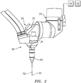
FIG. 2 is a schematic view of a laser cutting head of the laser cutting machine according toFIG. 1 . -
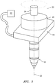
FIG. 3 is a schematic view of the laser cutting head with an adjustment collar. -
FIG. 4 is a schematic view of the adjustment collar. -
FIG. 5 is a block diagram flowchart of a method to align a laser and a process gas jet nozzle of the laser cutting head. -
FIG. 6 is a schematic view of a sacrificial hole and alignment relationship between the laser that cut the hole and the process gas jet nozzle that is utilized to measure the hole. -
FIG. 1 schematically illustrates alaser machine tool 20 in the form of a laser cutting machine. Thelaser machine tool 20 generally includes amachine bed 22, over which afirst joint 24 is movably guided in a first axial direction. Thefirst joint 24 supports asecond joint 26 with alaser cutting head 28. Jointly with thesecond joint 26, thelaser cutting head 28 is movable in a second axial direction relative thefirst joint 24. Furthermore, thelaser cutting head 28 is movable relative to thesecond joint 26 in a third axial direction. Beneath thelaser cutting head 28, a workpiece W is arranged on themachine bed 22. - With reference to
FIG. 2 , thelaser cutting head 28 includes alaser 30 that generates a laser beam along alaser beam axis 32. Thelaser 30 is contained within thelaser cutting head 28 and may be directed throughoptics 34 to direct the laser beam through a processgas jet nozzle 50. The mobility of thefirst joint 24 and thesecond joint 26 permits a desired point on the workpiece W to be machined with the laser cutting beam. The mobility of thelaser cutting head 28 in the Z-direction is used to adjust the focal position of the laser cutting beam in the direction transverse to the workpiece W. - A
motor drive 44 of thelaser machine tool 20, which is controlled by acontroller 46, is used to move thelaser cutting head 28. Themotor drive 44 may be operable to move thelaser cutting head 28 in a coordinate system. For example, a 6-axislaser machine tool 20 has the ability to interpolate either linearly for X, Y, Z, or rotationally A, B, and U. In addition, an R axis may be defined for each orientation of the coordinate systems when viewed isometrically. The R axis is an artificial axis created by the machine software that can move thelaser cutting head 28 parallel along a vector created normal to the workpiece W, however nomenclature often varies by machine. The operation of thelaser machine tool 20 may also be integrated into thecontroller 46 to position thelaser 30 and the associated processgas jet nozzle 50. Thecontroller 46 is operable to continually determine the position of thelaser cutting head 28 within the coordinate system. - The process
gas jet nozzle 50 is mounted to thelaser cutting head 28. A process gas jet, for example nitrogen, is directed from the processgas jet nozzle 50 to blow the molten metal formed at the machining point of the laser beam from the resulting kerf. Ideally, thelaser beam axis 32 from thelaser 30, and agas jet axis 52 of the processgas jet nozzle 50 coincide in a coaxial manner. That is, the laser beam is directed along thegas jet axis 52 of the processgas jet nozzle 50. - In routine operation of the
laser machine tool 20, however, the lasercutting beam axis 32 and the processgas jet axis 52 may move out of alignment. To adjust any variation of the actual relative positions of thelaser beam axis 32 and thegas jet axis 52 from the desired coaxial positioning, anadjustment collar 60 is mounted between thelaser cutting head 28 and the processgas jet nozzle 50 to adjust thelaser beam axis 32 and thegas jet axis 52. - With reference to
FIG. 3 , thecontroller 46 is operable to determine the position of thelaser cutting head 28 within the coordinate system. The processgas jet nozzle 50 is also utilized as a sensor for thecontroller 46 as the processgas jet nozzle 50 measures capacitance at a tip thereof to, for example, identify an edge of a hole in the workpiece W as the capacitance changes at the edge. Other methods for determining misalignment exist such as via a bore camera through the processgas jet nozzle 50. - With reference to
FIG. 4 , theadjustment collar 60 generally includes anouter housing 62 mounted to thelaser cutting head 28 and aninner collar 64 mounted to the processgas jet nozzle 50. An actuator 66 in the X-axis and anactuator 68 in the Y-axis are mounted between theouter housing 62inner collar 64 to position theinner collar 64 with respect to theouter housing 62. Theactuators actuators actuators controller 46. - With reference to
FIG. 5 , amethod 100 for positioning the laser beam and an associated process gas jet of thelaser machine tool 20 includes mounting (102) a sacrificial workpiece W in thelaser machine tool 20. - Next, an operator positions (104) the
laser cutting head 28 over the sacrificial workpiece W. The operator then loads (106) a subroutine for aligning thelaser beam axis 32 with respect to thegas jet axis 52 into thecontroller 46. The subroutine may be an algorithm or other machine program that operates on thecontroller 46. Once the operator initially positions thelaser cutting head 28 over the sacrificial workpiece W, the algorithm identifies this initial positon 200 (FIG. 6 ) as the initialgas jet axis 52 location and records this as the initial axis positon (108). - From the initial position, the algorithm activates the
laser 30 of thelaser cutting head 28 to cut (110) a hole "H" in the sacrificial workpiece W. The hole "H" that is cut may be of an arbitrary size, such as 0.5 inches (12.7 mm) in diameter. The laser beam at the focal point on the workpiece W is, for example, 0.005 inches (0.127 mm) in diameter. The exit of the processgas jet nozzle 50 is typically 0.060 - 0.080 inches (1.5 - 2.0 mm) in diameter. - The process
gas jet nozzle 50 initial positon (the initialgas jet axis 52 location) is the initiallaser beam axis 32 location if coaxially aligned. Thelaser 30, and thus thelaser beam axis 32, however, may be misaligned with thegas jet axis 52 and thus thelaser 30 is not coaxial with the processgas jet nozzle 50. This offset is determined and corrected by themethod 100. - Once the hole "H" is cut, the
controller 46 then utilizes the processgas jet nozzle 50 to scan (112) the hole "H" to determine an edge (114) of the hole. The hole "H" may be scanned along the X-axis and the Y-axis such that an edge is sensed by a change in capacitance sensed at the processgas jet nozzle 50. Since the hole is circular, only a few points on the edge need be determined to identify the hole location, diameter, and thus the center thereof. Thecontroller 46 then uses the edge location to calculate where a center (116) of the hole "H" is located in the sacrificial workpiece W. That is, the difference between thelaser beam axis 32 with respect to thegas jet axis 52 is determined because thelaser 30 cuts the hole "H" without knowing the center as the center is the initialgas jet axis 52 is obtained from the original position of thelaser cutting head 28, but the processgas jet nozzle 50 measures the hole "H" such that any discrepancy therebetween is identified. That is, thelaser cutting head 28 original position is known, but the processgas jet nozzle 50 may not be coaxial with thelaser 30. - The offset between the
laser beam axis 32 and thegas jet axis 52 is then determined (118) by thecontroller 46. The determined offset of thelaser beam axis 32 from thegas jet axis 52 forms the basis for a correction of the relative position of the twoaxes adjustment collar 60. The algorithm then utilizes the offset between thelaser beam axis 32 with respect to thegas jet axis 52 in the X and Y axes and communicates the location to thecontroller 46. The algorithm then adjusts (120) theactuators laser beam axis 32 and thegas jet axis 52 to compensate for the offset and bring the axes into a coaxial relationship. Theactuators laser beam axis 32 and thegas jet axis 52 with minimal operator intervention and facilitate increased alignment opportunities during manufacturing. - The
method 100 essentially removes operator intervention and potential error with respect to physically aligning the laser machine tool process gas jet nozzle and the laser. This facilitates replacement of the current style set screw aperture that exists with an electronically controlled aperture of the same form factor. The piezoelectric motors move accurately in the X-Y plane using feedback from the algorithm such that thelaser beam axis 32 and thegas jet axis 52 automatically align. Theadjustment collar 60 does not increase the physical size of thelaser cutting head 28 and are readily retrofitted. - Although the different non-limiting embodiments have specific illustrated components, the embodiments of this invention are not limited to those particular combinations. It is possible to use some of the components or features from any of the non-limiting embodiments in combination with features or components from any of the other non-limiting embodiments.
- It should be appreciated that relative positional terms such as "forward," "aft," "upper," "lower," "above," "below," and the like are with reference to the normal operational attitude of the vehicle and should not be considered otherwise limiting.
- It should be appreciated that like reference numerals identify corresponding or similar elements throughout the several drawings. It should also be appreciated that although a particular component arrangement is disclosed in the illustrated embodiment, other arrangements will benefit herefrom.
- Although particular sequences are shown, described, and claimed, it should be appreciated that steps may be performed in any order, separated or combined unless otherwise indicated and will still benefit from the present disclosure.
- The foregoing description is exemplary rather than defined by the limitations within. Various non-limiting embodiments are disclosed herein, however, one of ordinary skill in the art would recognize that various modifications and variations in light of the above teachings will fall within the scope of the appended claims. It is therefore to be appreciated that within the scope of the appended claims, the disclosure may be practiced other than as specifically described. For that reason the appended claims should be studied to determine true scope and content.
Claims (15)
- An adjustment collar for a laser machine tool, comprising:an outer housing;an inner collar;a first actuator between the outer housing and the inner collar, the first actuator operable to move the inner collar with respect to the outer housing along an X-axis; anda second actuator between the outer housing and the inner collar, the second actuator operable to move the inner collar with respect to the outer housing along a Y-axis.
- The adjustment collar as recited in claim 1, wherein the first actuator and the second actuator are piezoelectric motors.
- The adjustment collar as recited in claim 1 or 2, wherein the outer housing is mountable to a laser cutting head.
- The adjustment collar as recited in claim 1, 2 or 3, wherein the inner collar is mountable to a process gas jet nozzle.
- The adjustment collar as recited in any preceding claim, further comprising a controller in communication with the first actuator and the second actuator.
- A laser machine tool, comprising:a laser that defines a laser beam axis;a process gas jet nozzle that defines a gas jet axis;an adjustment collar mounted with respect to the laser and the process gas jet nozzle; anda controller in communication with the adjustment collar to move the process gas jet nozzle with respect to the laser to position the laser beam axis with respect to the gas jet axis.
- The laser machine tool as recited in claim 6, further comprising an outer housing of the adjustment collar, the outer housing mounted to a laser cutting head that contains the laser.
- The laser machine tool as recited in claim 6 or 7, further comprising an inner collar of the adjustment collar mounted to the process gas jet nozzle.
- The laser machine tool as recited in claim 8, further comprising
a first actuator between the outer housing and the inner collar, the first actuator operable to move the inner collar with respect to the outer housing in an X-axis; and
a second actuator between the outer housing and the inner collar, the second actuator operable to move the inner collar with respect to the outer housing in a Y-axis, wherein the first actuator and the second actuator are optionally piezoelectric motors. - A method for adjusting an adjusting collar to move a process gas jet nozzle with respect to a laser cutting head to align a gas jet axis with respect to a laser beam axis, the method comprising:adjusting a first actuator between an outer housing of an adjusting collar mounted to a laser cutting head and an inner collar of the adjusting collar, the first actuator operable to move the inner collar with respect to the outer housing along an X-axis; andadjusting a second actuator between the outer housing of the adjusting collar mounted to the laser cutting head and the inner collar of the adjusting collar, the second actuator between the outer housing and the inner collar, the second actuator operable to move the inner collar with respect to the outer housing along a Y-axis.
- The method as recited in claim 10, further comprising:determining a location of the laser beam axis based on a positon of the laser cutting head;cutting a hole in a sacrificial workpiece with the laser of the laser cutting head;measuring the hole with a process gas jet nozzle mounted to the laser cutting head to determine a location of a gas jet axis at a center of the hole;comparing the location of the gas jet axis with respect to the location of the laser beam axis; andadjusting the adjusting collar to move the process gas jet nozzle with respect to the laser cutting head to align the gas jet axis with respect to the laser beam axis,wherein, optionally, determining the location of the laser beam axis is presumed to be a central axis of the laser cutting head.
- The method as recited in claim 11, further comprising:determining a capacitance with the process gas jet nozzle to find the edge of the hole.
- The method as recited in claim 12, further comprising moving the process gas jet nozzle along an X- axis and/or an Y- axis.
- The method as recited in claim 11, 12 or 13, further comprising automatically adjusting the adjusting collar in response to a controller to align the first axis location to the center of the hole.
- The method as recited in any of claims 11-14, wherein to align the first axis location to the center of the hole aligns a gas jet axis with respect to a laser beam axis, for example such that the axes are coaxial.
Applications Claiming Priority (1)
| Application Number | Priority Date | Filing Date | Title |
|---|---|---|---|
| US15/708,730 US10953492B2 (en) | 2017-09-19 | 2017-09-19 | Method and apparatus for auto-aligning of a process gas jet nozzle and laser machining beam |
Publications (2)
| Publication Number | Publication Date |
|---|---|
| EP3456459A1 true EP3456459A1 (en) | 2019-03-20 |
| EP3456459B1 EP3456459B1 (en) | 2025-11-26 |
Family
ID=63642826
Family Applications (1)
| Application Number | Title | Priority Date | Filing Date |
|---|---|---|---|
| EP18195416.5A Active EP3456459B1 (en) | 2017-09-19 | 2018-09-19 | Method and apparatus for auto-aligning of a process gas jet nozzle and laser machining beam |
Country Status (2)
| Country | Link |
|---|---|
| US (2) | US10953492B2 (en) |
| EP (1) | EP3456459B1 (en) |
Families Citing this family (2)
| Publication number | Priority date | Publication date | Assignee | Title |
|---|---|---|---|---|
| US10500690B2 (en) * | 2017-10-25 | 2019-12-10 | United Technologies Corporation | Method and apparatus for aligning a process gas jet nozzle and laser machining beam |
| CN110549006A (en) * | 2019-08-13 | 2019-12-10 | 江苏屹诚激光装备制造有限公司 | Efficient laser cutting equipment |
Citations (5)
| Publication number | Priority date | Publication date | Assignee | Title |
|---|---|---|---|---|
| US4427873A (en) * | 1982-03-18 | 1984-01-24 | Amada Engineering & Service Co. | Method and apparatus for aligning axes of assisting gas nozzles with laser beam axes in laser processing machines |
| JPH02217188A (en) * | 1989-02-17 | 1990-08-29 | Mitsubishi Electric Corp | Laser beam machining head |
| EP1600248A2 (en) * | 2004-05-26 | 2005-11-30 | Yamazaki Mazak Corporation | Nozzle presetter for laser machining tool of laser beam machine |
| JP3761657B2 (en) * | 1997-03-10 | 2006-03-29 | 株式会社アマダ | Laser processing method and apparatus |
| CH703957B1 (en) * | 2009-09-22 | 2014-04-30 | Precitec Kg | Laser processing head having a Fokuslagenjustageeinheit as well as a system and a method for adjusting a focal position of a laser beam. |
Family Cites Families (6)
| Publication number | Priority date | Publication date | Assignee | Title |
|---|---|---|---|---|
| US4581808A (en) * | 1982-02-04 | 1986-04-15 | The Charles Stark Draper Laboratory | Adjustable machining system and implement therefore |
| JP2003170287A (en) | 2001-12-07 | 2003-06-17 | Amada Eng Center Co Ltd | Method and device for alignment of nozzle of laser processing apparatus |
| JP5165485B2 (en) | 2008-07-22 | 2013-03-21 | 日本車輌製造株式会社 | Laser cutting device |
| TW201444632A (en) | 2013-05-27 | 2014-12-01 | Nippon Sharyo Ltd | Laser processing machine |
| US9682441B2 (en) * | 2015-06-01 | 2017-06-20 | Caterpillar Inc. | Laser polishing system and method for metal face seal |
| JP7274948B2 (en) * | 2019-06-11 | 2023-05-17 | ニデックマシンツール株式会社 | Three-dimensional lamination apparatus and method |
-
2017
- 2017-09-19 US US15/708,730 patent/US10953492B2/en active Active
-
2018
- 2018-09-19 EP EP18195416.5A patent/EP3456459B1/en active Active
-
2021
- 2021-03-23 US US17/210,061 patent/US11660703B2/en active Active
Patent Citations (5)
| Publication number | Priority date | Publication date | Assignee | Title |
|---|---|---|---|---|
| US4427873A (en) * | 1982-03-18 | 1984-01-24 | Amada Engineering & Service Co. | Method and apparatus for aligning axes of assisting gas nozzles with laser beam axes in laser processing machines |
| JPH02217188A (en) * | 1989-02-17 | 1990-08-29 | Mitsubishi Electric Corp | Laser beam machining head |
| JP3761657B2 (en) * | 1997-03-10 | 2006-03-29 | 株式会社アマダ | Laser processing method and apparatus |
| EP1600248A2 (en) * | 2004-05-26 | 2005-11-30 | Yamazaki Mazak Corporation | Nozzle presetter for laser machining tool of laser beam machine |
| CH703957B1 (en) * | 2009-09-22 | 2014-04-30 | Precitec Kg | Laser processing head having a Fokuslagenjustageeinheit as well as a system and a method for adjusting a focal position of a laser beam. |
Also Published As
| Publication number | Publication date |
|---|---|
| US20190084084A1 (en) | 2019-03-21 |
| US20210205923A1 (en) | 2021-07-08 |
| US10953492B2 (en) | 2021-03-23 |
| US11660703B2 (en) | 2023-05-30 |
| EP3456459B1 (en) | 2025-11-26 |
Similar Documents
| Publication | Publication Date | Title |
|---|---|---|
| US7528344B2 (en) | Determining the relative positions of the axes of a laser machining beam and a process gas jet | |
| CN110026813B (en) | Nozzle control device for machine tool | |
| US11752572B2 (en) | Method and laser processing machining for laser welding a first and a second workpiece portion | |
| JP6913102B2 (en) | Beam processing machine axis calibration | |
| US8367962B2 (en) | Automated welding of moulds and stamping tools | |
| US5095788A (en) | Method for compensating thermally induced displacement in machine tools | |
| CN100441359C (en) | Nozzle preset device for laser processing tool in laser processing machine | |
| EP2584419B1 (en) | CNC machine for cutting with plasma, oxygen and water jet used as a cutting tool with automatic setting up a precise position of a cutting tool in a cutting head by autocalibration and method thereof | |
| KR102104707B1 (en) | Initial distance approach for laser processing | |
| US11660703B2 (en) | Method and apparatus for auto-aligning of a process gas jet nozzle and laser machining beam | |
| US20180056465A1 (en) | Fluid ejection device | |
| KR20150092320A (en) | Three-dimensional laser processing machine | |
| JP2002515344A (en) | Method of processing workpieces and machine tools | |
| JP3829114B2 (en) | Numerical controller | |
| EP3479948B1 (en) | Method and apparatus for aligning a process gas jet nozzle and laser machining beam | |
| JP7457108B2 (en) | Tool measuring system and control method | |
| US20230001502A1 (en) | Method for the Thermal Processing of a Workpiece with a Thermal Processing Machine | |
| KR101503304B1 (en) | Position and attitude setting method of lug welding robot using laser pointer | |
| US20190134768A1 (en) | Method and apparatus for water jet cutting standoff height | |
| CN108055834B (en) | Machine for laser machining of profiles and associated method | |
| KR102440569B1 (en) | Laser processing device | |
| JP2019051528A (en) | Misalignment detection method, misalignment correction method, misalignment detection apparatus, misalignment correction apparatus | |
| CN117597639A (en) | Methods for compensating tool offsets when machining workpieces and machine tools for this | |
| US20260091489A1 (en) | Robot control device and plasma cutting method | |
| JP2646890B2 (en) | Control method of laser cutting robot |
Legal Events
| Date | Code | Title | Description |
|---|---|---|---|
| PUAI | Public reference made under article 153(3) epc to a published international application that has entered the european phase |
Free format text: ORIGINAL CODE: 0009012 |
|
| STAA | Information on the status of an ep patent application or granted ep patent |
Free format text: STATUS: THE APPLICATION HAS BEEN PUBLISHED |
|
| AK | Designated contracting states |
Kind code of ref document: A1 Designated state(s): AL AT BE BG CH CY CZ DE DK EE ES FI FR GB GR HR HU IE IS IT LI LT LU LV MC MK MT NL NO PL PT RO RS SE SI SK SM TR |
|
| AX | Request for extension of the european patent |
Extension state: BA ME |
|
| STAA | Information on the status of an ep patent application or granted ep patent |
Free format text: STATUS: REQUEST FOR EXAMINATION WAS MADE |
|
| 17P | Request for examination filed |
Effective date: 20190920 |
|
| RBV | Designated contracting states (corrected) |
Designated state(s): AL AT BE BG CH CY CZ DE DK EE ES FI FR GB GR HR HU IE IS IT LI LT LU LV MC MK MT NL NO PL PT RO RS SE SI SK SM TR |
|
| RAP1 | Party data changed (applicant data changed or rights of an application transferred) |
Owner name: RAYTHEON TECHNOLOGIES CORPORATION |
|
| STAA | Information on the status of an ep patent application or granted ep patent |
Free format text: STATUS: EXAMINATION IS IN PROGRESS |
|
| 17Q | First examination report despatched |
Effective date: 20220225 |
|
| RAP3 | Party data changed (applicant data changed or rights of an application transferred) |
Owner name: RTX CORPORATION |
|
| GRAP | Despatch of communication of intention to grant a patent |
Free format text: ORIGINAL CODE: EPIDOSNIGR1 |
|
| STAA | Information on the status of an ep patent application or granted ep patent |
Free format text: STATUS: GRANT OF PATENT IS INTENDED |
|
| INTG | Intention to grant announced |
Effective date: 20250616 |
|
| GRAS | Grant fee paid |
Free format text: ORIGINAL CODE: EPIDOSNIGR3 |
|
| GRAA | (expected) grant |
Free format text: ORIGINAL CODE: 0009210 |
|
| STAA | Information on the status of an ep patent application or granted ep patent |
Free format text: STATUS: THE PATENT HAS BEEN GRANTED |
|
| AK | Designated contracting states |
Kind code of ref document: B1 Designated state(s): AL AT BE BG CH CY CZ DE DK EE ES FI FR GB GR HR HU IE IS IT LI LT LU LV MC MK MT NL NO PL PT RO RS SE SI SK SM TR |
|
| REG | Reference to a national code |
Ref country code: CH Ref legal event code: F10 Free format text: ST27 STATUS EVENT CODE: U-0-0-F10-F00 (AS PROVIDED BY THE NATIONAL OFFICE) Effective date: 20251126 Ref country code: GB Ref legal event code: FG4D |
|
| REG | Reference to a national code |
Ref country code: IE Ref legal event code: FG4D |
|
| REG | Reference to a national code |
Ref country code: DE Ref legal event code: R096 Ref document number: 602018087405 Country of ref document: DE |
|
| REG | Reference to a national code |
Ref country code: NL Ref legal event code: MP Effective date: 20251126 |
|
| PG25 | Lapsed in a contracting state [announced via postgrant information from national office to epo] |
Ref country code: ES Free format text: LAPSE BECAUSE OF FAILURE TO SUBMIT A TRANSLATION OF THE DESCRIPTION OR TO PAY THE FEE WITHIN THE PRESCRIBED TIME-LIMIT Effective date: 20251126 |
|
| REG | Reference to a national code |
Ref country code: LT Ref legal event code: MG9D |
|
| PG25 | Lapsed in a contracting state [announced via postgrant information from national office to epo] |
Ref country code: NO Free format text: LAPSE BECAUSE OF FAILURE TO SUBMIT A TRANSLATION OF THE DESCRIPTION OR TO PAY THE FEE WITHIN THE PRESCRIBED TIME-LIMIT Effective date: 20260226 |
|
| PG25 | Lapsed in a contracting state [announced via postgrant information from national office to epo] |
Ref country code: FI Free format text: LAPSE BECAUSE OF FAILURE TO SUBMIT A TRANSLATION OF THE DESCRIPTION OR TO PAY THE FEE WITHIN THE PRESCRIBED TIME-LIMIT Effective date: 20251126 Ref country code: HR Free format text: LAPSE BECAUSE OF FAILURE TO SUBMIT A TRANSLATION OF THE DESCRIPTION OR TO PAY THE FEE WITHIN THE PRESCRIBED TIME-LIMIT Effective date: 20251126 Ref country code: AT Free format text: LAPSE BECAUSE OF FAILURE TO SUBMIT A TRANSLATION OF THE DESCRIPTION OR TO PAY THE FEE WITHIN THE PRESCRIBED TIME-LIMIT Effective date: 20251126 |
|
| REG | Reference to a national code |
Ref country code: AT Ref legal event code: MK05 Ref document number: 1860624 Country of ref document: AT Kind code of ref document: T Effective date: 20251126 |
|
| PG25 | Lapsed in a contracting state [announced via postgrant information from national office to epo] |
Ref country code: NL Free format text: LAPSE BECAUSE OF FAILURE TO SUBMIT A TRANSLATION OF THE DESCRIPTION OR TO PAY THE FEE WITHIN THE PRESCRIBED TIME-LIMIT Effective date: 20251126 |
|
| PG25 | Lapsed in a contracting state [announced via postgrant information from national office to epo] |
Ref country code: RS Free format text: LAPSE BECAUSE OF FAILURE TO SUBMIT A TRANSLATION OF THE DESCRIPTION OR TO PAY THE FEE WITHIN THE PRESCRIBED TIME-LIMIT Effective date: 20260226 |
|
| PG25 | Lapsed in a contracting state [announced via postgrant information from national office to epo] |
Ref country code: IS Free format text: LAPSE BECAUSE OF FAILURE TO SUBMIT A TRANSLATION OF THE DESCRIPTION OR TO PAY THE FEE WITHIN THE PRESCRIBED TIME-LIMIT Effective date: 20260326 |
|
| PG25 | Lapsed in a contracting state [announced via postgrant information from national office to epo] |
Ref country code: PT Free format text: LAPSE BECAUSE OF FAILURE TO SUBMIT A TRANSLATION OF THE DESCRIPTION OR TO PAY THE FEE WITHIN THE PRESCRIBED TIME-LIMIT Effective date: 20260326 |
|
| PG25 | Lapsed in a contracting state [announced via postgrant information from national office to epo] |
Ref country code: PL Free format text: LAPSE BECAUSE OF FAILURE TO SUBMIT A TRANSLATION OF THE DESCRIPTION OR TO PAY THE FEE WITHIN THE PRESCRIBED TIME-LIMIT Effective date: 20251126 |
|
| PG25 | Lapsed in a contracting state [announced via postgrant information from national office to epo] |
Ref country code: LV Free format text: LAPSE BECAUSE OF FAILURE TO SUBMIT A TRANSLATION OF THE DESCRIPTION OR TO PAY THE FEE WITHIN THE PRESCRIBED TIME-LIMIT Effective date: 20251126 |
|
| PG25 | Lapsed in a contracting state [announced via postgrant information from national office to epo] |
Ref country code: BG Free format text: LAPSE BECAUSE OF FAILURE TO SUBMIT A TRANSLATION OF THE DESCRIPTION OR TO PAY THE FEE WITHIN THE PRESCRIBED TIME-LIMIT Effective date: 20251126 |