EP3456237B1 - Lave-vaisselle comprenant au moins une pompe à chaleur - Google Patents
Lave-vaisselle comprenant au moins une pompe à chaleur Download PDFInfo
- Publication number
- EP3456237B1 EP3456237B1 EP18192947.2A EP18192947A EP3456237B1 EP 3456237 B1 EP3456237 B1 EP 3456237B1 EP 18192947 A EP18192947 A EP 18192947A EP 3456237 B1 EP3456237 B1 EP 3456237B1
- Authority
- EP
- European Patent Office
- Prior art keywords
- heat pump
- phase
- heating
- cycle
- valves
- Prior art date
- Legal status (The legal status is an assumption and is not a legal conclusion. Google has not performed a legal analysis and makes no representation as to the accuracy of the status listed.)
- Active
Links
- 239000012071 phase Substances 0.000 claims description 135
- 238000010438 heat treatment Methods 0.000 claims description 80
- 238000005406 washing Methods 0.000 claims description 64
- 238000004140 cleaning Methods 0.000 claims description 18
- 238000001035 drying Methods 0.000 claims description 12
- 239000012073 inactive phase Substances 0.000 claims description 5
- 239000011521 glass Substances 0.000 claims description 3
- XLYOFNOQVPJJNP-UHFFFAOYSA-N water Substances O XLYOFNOQVPJJNP-UHFFFAOYSA-N 0.000 description 30
- 238000000034 method Methods 0.000 description 12
- 230000008569 process Effects 0.000 description 12
- 239000007788 liquid Substances 0.000 description 11
- 238000011161 development Methods 0.000 description 7
- 230000018109 developmental process Effects 0.000 description 7
- 230000007704 transition Effects 0.000 description 6
- 230000006835 compression Effects 0.000 description 5
- 238000007906 compression Methods 0.000 description 5
- 239000003599 detergent Substances 0.000 description 5
- 230000000694 effects Effects 0.000 description 5
- 238000001816 cooling Methods 0.000 description 4
- 230000001052 transient effect Effects 0.000 description 4
- 238000011144 upstream manufacturing Methods 0.000 description 4
- 238000010792 warming Methods 0.000 description 3
- 230000006978 adaptation Effects 0.000 description 2
- 239000003990 capacitor Substances 0.000 description 2
- 239000002826 coolant Substances 0.000 description 2
- 238000010586 diagram Methods 0.000 description 2
- 238000005265 energy consumption Methods 0.000 description 2
- 230000006872 improvement Effects 0.000 description 2
- 238000012423 maintenance Methods 0.000 description 2
- 238000005057 refrigeration Methods 0.000 description 2
- 238000004904 shortening Methods 0.000 description 2
- 230000002123 temporal effect Effects 0.000 description 2
- 230000008859 change Effects 0.000 description 1
- 239000012459 cleaning agent Substances 0.000 description 1
- 238000011109 contamination Methods 0.000 description 1
- 238000010411 cooking Methods 0.000 description 1
- 230000008878 coupling Effects 0.000 description 1
- 238000010168 coupling process Methods 0.000 description 1
- 238000005859 coupling reaction Methods 0.000 description 1
- 230000007423 decrease Effects 0.000 description 1
- 239000002274 desiccant Substances 0.000 description 1
- 238000000605 extraction Methods 0.000 description 1
- 230000002349 favourable effect Effects 0.000 description 1
- 239000013505 freshwater Substances 0.000 description 1
- 230000003287 optical effect Effects 0.000 description 1
- 239000003507 refrigerant Substances 0.000 description 1
- 230000000717 retained effect Effects 0.000 description 1
- 239000007787 solid Substances 0.000 description 1
- 239000000126 substance Substances 0.000 description 1
- 239000002918 waste heat Substances 0.000 description 1
Images


Classifications
-
- A—HUMAN NECESSITIES
- A47—FURNITURE; DOMESTIC ARTICLES OR APPLIANCES; COFFEE MILLS; SPICE MILLS; SUCTION CLEANERS IN GENERAL
- A47L—DOMESTIC WASHING OR CLEANING; SUCTION CLEANERS IN GENERAL
- A47L15/00—Washing or rinsing machines for crockery or tableware
- A47L15/42—Details
- A47L15/4291—Recovery arrangements, e.g. for the recovery of energy or water
-
- A—HUMAN NECESSITIES
- A47—FURNITURE; DOMESTIC ARTICLES OR APPLIANCES; COFFEE MILLS; SPICE MILLS; SUCTION CLEANERS IN GENERAL
- A47L—DOMESTIC WASHING OR CLEANING; SUCTION CLEANERS IN GENERAL
- A47L2501/00—Output in controlling method of washing or rinsing machines for crockery or tableware, i.e. quantities or components controlled, or actions performed by the controlling device executing the controlling method
- A47L2501/32—Stopping or disabling machine operation, including disconnecting the machine from a network, e.g. from an electrical power supply
-
- D—TEXTILES; PAPER
- D06—TREATMENT OF TEXTILES OR THE LIKE; LAUNDERING; FLEXIBLE MATERIALS NOT OTHERWISE PROVIDED FOR
- D06F—LAUNDERING, DRYING, IRONING, PRESSING OR FOLDING TEXTILE ARTICLES
- D06F39/00—Details of washing machines not specific to a single type of machines covered by groups D06F9/00 - D06F27/00
- D06F39/04—Heating arrangements
-
- D—TEXTILES; PAPER
- D06—TREATMENT OF TEXTILES OR THE LIKE; LAUNDERING; FLEXIBLE MATERIALS NOT OTHERWISE PROVIDED FOR
- D06F—LAUNDERING, DRYING, IRONING, PRESSING OR FOLDING TEXTILE ARTICLES
- D06F58/00—Domestic laundry dryers
- D06F58/20—General details of domestic laundry dryers
- D06F58/206—Heat pump arrangements
-
- Y—GENERAL TAGGING OF NEW TECHNOLOGICAL DEVELOPMENTS; GENERAL TAGGING OF CROSS-SECTIONAL TECHNOLOGIES SPANNING OVER SEVERAL SECTIONS OF THE IPC; TECHNICAL SUBJECTS COVERED BY FORMER USPC CROSS-REFERENCE ART COLLECTIONS [XRACs] AND DIGESTS
- Y02—TECHNOLOGIES OR APPLICATIONS FOR MITIGATION OR ADAPTATION AGAINST CLIMATE CHANGE
- Y02B—CLIMATE CHANGE MITIGATION TECHNOLOGIES RELATED TO BUILDINGS, e.g. HOUSING, HOUSE APPLIANCES OR RELATED END-USER APPLICATIONS
- Y02B30/00—Energy efficient heating, ventilation or air conditioning [HVAC]
- Y02B30/52—Heat recovery pumps, i.e. heat pump based systems or units able to transfer the thermal energy from one area of the premises or part of the facilities to a different one, improving the overall efficiency
Definitions
- the present invention relates to a household dishwasher with a washing container for holding dishes, glasses, cutlery or similar items to be washed, and with at least one heat pump.
- the dishwasher of the WO 2015/090409 A1 has a heat pump system with a first condenser or condenser and a second condenser.
- the heat pump system can be switched by means of two valves between a first configuration, in which its compressor is connected to the first condenser for heating rinse water in a rinsing phase of a dishwashing program to be carried out, and a second configuration, in which its evaporator emits moist air during the drying phase of the dishwashing program cools the rinsing tank of the dishwasher to condense moisture and its compressor is connected to the second condenser for heating the dehumidified air. The dehumidified and heated air is returned to the rinsing tank.
- the heat pump system of the dishwasher CN 106 606 342 A comprises a first condenser and a second condenser.
- a changeover valve in the heat pump system ensures that coolant flows from the compressor of the heat pump system to the first condenser when washing water is to be warmed up for a washing phase of a dishwasher program and sprayed onto washware to be cleaned in the dishwasher's washing container. It selectively switches the coolant flow to the second condenser in the drying cycle.
- This second condenser is arranged in a circulating air duct, viewed in the air flow direction, after the evaporator of the heat pump arrangement.
- moist air that flows from the rinsing container into the circulating air duct is first cooled with the aid of the evaporator, as a result of which moisture is condensed out, and then the air dried in this way is heated again with the aid of the second condenser and then returned to the rinsing container, to absorb moisture again.
- the dishwasher of the CH 699 692 A2 has a first water tank for temporarily holding process water coming out of its rinsing tub and a second water tank for temporarily holding process water or fresh water coming out of its rinsing tub.
- tank valves are provided in order to feed the process water either to the first or the second water tank from the sump of the rinsing tub by means of a drain pump.
- a first condenser of a heat pump serves to supply heat to the process water in the rinsing tub and / or in a circulation circuit connected to the tub.
- a second condenser of the heat pump is used to supply heat to the process water in the second water tank.
- a changeover valve in the heat pump By means of a changeover valve in the heat pump, its heat pump medium can be supplied to either the first or the second condenser.
- a second evaporator of the heat pump arrangement is in thermal contact with the process water in the second water tank for heat extraction.
- the first and the second evaporator can be operated optionally, for which purpose a changeover valve is provided after the expansion valve of the heat pump, with which the heat pump medium can be supplied from the expansion valve to either the first or the second evaporator.
- the process water of the intermediate rinsing phase of a dishwasher program is fed to the second water tank, while that of the main rinsing phase of the dishwasher program is fed to the first water tank.
- both water tanks contain warm water, but at different temperatures.
- the temperature in the first water tank will be higher than the temperature in the second water tank. Since the coefficient of performance of a heat pump gets better the smaller the temperature difference is, the efficiency of the dishwasher can be improved if the cold process water in the washing tub is first heated in the rinse phase of the dishwasher program by the heat pump extracting heat from the colder water tank and this from the process water feeds, and only when the process water is already warmer, the changeover valve is switched to extract heat from the water tank with the higher temperature.
- the heat pump of the dishwasher of the DE 197 07 287 A1 for waste heat utilization of the exhaust air from the dishwasher device comprises two separate cooling circuits, each with a first heat exchanger in heat exchange with the exhaust air from the dishwasher device, the first cooling circuit comprising at least a second one Contains heat exchanger in heat exchange with a rinse water of the dishwasher, and the second refrigeration circuit has at least a third heat exchanger, which is operatively connected to a tank heater in a cleaning liquid collecting container of the dishwasher.
- the third heat exchanger is a condenser. It is connected to the compressor of the second refrigeration circuit by means of a disconnect coupling, so that the main unit and the heat exchanger can be evacuated separately and filled with refrigerant.
- the invention is therefore based on the problem of being able to use a heat pump of a household dishwasher as energy-efficiently as possible.
- a first valve and a second valve are arranged in front of a part of the heat pump that emits heat during operation of the heat pump, the temperature and / or pressure conditions prevailing during operation can also be there at least for a time, even in a switched-off or inactive phase of the heat pump are retained for a long time, so that when the heat pump is switched on again later, the energy conditions are significantly improved.
- the heat-emitting part of the heat pump is a condenser.
- the valves are upstream and downstream of a condenser, also referred to as a condenser, so that when the unit is switched on again, the physical state of the heat pump medium or heat exchange medium is also present and a long and energetically ineffective start-up time of the heat pump can be avoided.
- the heat pump is in each case active in at least two phases of a rinsing cycle to be carried out in each case to support respective heating, so that the conditions achieved in the first phase can then be "preserved" for the second phase by closing the valves after the end of the first active phase .
- the first valve is preferably inserted in the area of the condenser inlet into the transport line leading from the compressor to the condenser, in which a heat pump medium or heat exchange medium is conveyed from the compressor to the condenser during operation of the compressor, or is provided in the inlet of the condenser.
- the second valve is preferably inserted in the area of the condenser outlet into the transport line leading from the condenser to the expansion device, in particular capillary tubes or throttle, of the heat pump, in which the heat pump medium or heat exchange medium is conveyed from the condenser to the expansion device when the compressor is operating, or in Condenser outlet provided.
- the condenser can be shut off on the inlet side and outlet side during an inactive phase of the heat pump, that is to say during the period of time that lies between two phases of a rinsing cycle to be carried out, each with an actively operated heat pump, so that in it Existing heat pump medium cannot escape from the condenser to the evaporator and the compressor of the heat pump, and its aggregate state, energetic state and pressure state from the first active operating phase of the heat pump during the pause, i.e. the inactive phase of the heat pump until the second active phase that follows later largely maintains the heat pump.
- the heat pump has a controllable expansion valve as a relaxation device between the condenser and the evaporator, this can possibly form the second valve downstream of the condenser, which can be brought into a closed position or a throttle position such that the heat pump medium flows when the heat pump is inactive or working medium of the heat pump from its high-pressure side to the low-pressure side can be prevented or greatly reduced, so that when the compressor is started again for a later, second heating phase with largely the same pressure difference between the high pressure side and the low-pressure side of the heat pump as at the end of the first heating phase Heat pump can be continued.
- a controllable expansion valve as a relaxation device between the condenser and the evaporator
- the first phase to support heating is part of a liquid-carrying partial rinse cycle of a rinse cycle, in particular the so-called cleaning cycle of the rinse cycle of a household dishwasher, in which water mixed with detergent is warmed up.
- the second phase to support heating can be part of a further liquid-carrying partial rinse cycle, in particular the so-called rinse cycle, the rinse cycle of a household dishwasher, or the drying cycle of the rinse cycle, in which after an interim cooling preferably an even higher temperature than in the earlier liquid-carrying partial rinse cycle should be achieved with the first warming phase.
- High energy efficiency is therefore particularly important here.
- valves can close after the end of the first phase to support heating, in particular immediately after the end of the first phase.
- valves can be opened again before the start of the second phase to support warming, in particular also here to optimize efficiency immediately before the start of the second phase to support one Warming.
- the first active phase of the heat pump is part of a first liquid-carrying partial washing cycle, in particular the cleaning cycle, of a washing cycle to be carried out
- the second active phase is part of a second liquid-carrying partial washing cycle, in particular rinse cycle, the washing cycle, wherein the first valve and the second valve are open during the first active phase and the second active phase of the heat pump, whereas the first valve and the second valve in the period between the first active phase and the second active phase of the heat pump, during which the heat pump is inactive, are each closed.
- the pressure ratios and / or the temperature reached during the first phase can be at least almost maintained with the valves closed, so that the second phase can then be started immediately and without a long start-up time.
- Both valves can very advantageously be of the same design, so that the assembly is not prone to errors and the number of parts remains small.
- the opening and closing behavior of the two valves can be stored in a control program on the software side and in adaptation to the other program conditions
- a household appliance shown schematically, is a dishwasher, specifically a domestic dishwasher 1.
- the household dishwasher 1 described below Figure 1 has as part of a partially open or closed appliance body 5 a washing container 2 for receiving items to be processed such as dishes, pots, cutlery, glasses, cooking utensils and. on.
- the items to be washed can, for example, be held in crockery baskets 11 and / or a cutlery drawer 10 and can be loaded with so-called washing liquor.
- the rinsing liquor can also be contaminated with contamination from ongoing operation.
- the rinsing container 2 can have an at least substantially rectangular plan with a front side V facing the user in the operating position.
- This front side V can form part of a kitchen front from kitchen furniture standing next to one another or, in the case of a stand-alone device, also without reference to other furniture.
- the washing compartment 2 can be closed in particular on this front side V by a door or flap 3.
- This door 3 is in Figure 1 shown in a partially open position and then at an angle to the vertical. In its closed position, on the other hand, it stands upright and, according to the drawing, can be swiveled forward and downward in the direction of arrow 4 about its opening about a lower horizontal axis, so that it is at least almost horizontal in the fully open position.
- the door 3 On its outer and front side V, which is vertical in the closed position and faces the user, the door 3 can be provided with a decorative plate 6 in order to experience an optical and / or haptic upgrade and / or an adaptation to surrounding kitchen furniture.
- the dishwasher is designed as a stand-alone device or as a so-called partially integrated or fully integrated device.
- the device body 5 can also essentially end with the outer walls of the washing compartment 2.
- a housing surrounding this outside can then be dispensed with.
- a base 12 for receiving, in particular, functional elements, such as a circulating pump for the washing liquor.
- This circulation pump can in particular also be heated, in order to bring the washing liquor to the temperature desired in the respective program step.
- An external heating system that is independent of the circulation pump can be additionally or alternatively provided.
- the movable door 3 is preferably assigned in its upper region an operating panel 8 which extends in the transverse direction Q of the dishwasher and which can include an engagement opening 7 accessible from the front V for manual opening and / or closing of the door 3.
- the dishwasher In the transverse direction Q the dishwasher often has an extension of 45, 50 or 60 centimeters. In the depth direction from the front V to the rear, the extent is often also around 60 centimeters. The values are not mandatory.
- the washing compartment 2 is delimited all around by three solid vertical walls 13 and two horizontal walls 13 when the door or flap 3 is closed, one of which forms a ceiling (above) and another forms a bottom (below) of the washing compartment 2.
- the wall 13 forming the bottom of the washing compartment 2 and essentially delimiting it downwards lies approximately horizontally, that is to say parallel to an outer bottom B on which the dishwasher 1 stands.
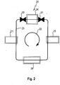
- the household appliance 1 is further provided with at least one heat pump 20, the components of which can be arranged at different locations in the household appliance 1 - also distributed.
- the heat pump 20 comprises a compressor (also called a compressor) 21, in which work is carried out on the circulating heat pump medium 23, so that this medium 23 is heated.
- a compressor also called a compressor
- the compressor 21 is followed by a condenser or condenser or condenser 24.
- the medium 23 condenses from the gaseous to the liquid state during the operation of the heat pump 20 and gives heat to the environment there through this phase change from, in particular to the above-mentioned washing liquor and / or the air in the washing container 2.
- the condenser 24 thus also acts as a heat exchanger. This results in heating of the washing liquor or washing liquid and / or air in the washing container 2, so that an additional electric heater can be made smaller and run shorter than without the heat pump 20. Depending on the design, an additional electric heater can also be dispensed with entirely.
- the heating of rinsing liquid and / or air in the rinsing container is then carried out solely by means of the heat pump.
- the washing liquor and / or air in the washing container 2 is heated up, there is a large amount of energetic support from the heat pump.
- the condenser or liquefier 24 is followed in the flow direction 22 by a throttle, in particular a capillary tube or similar expansion device 25, to which an evaporator 26 is connected in the flow direction 22, in which the previously liquid medium 23 becomes gaseous again.
- a throttle in particular a capillary tube or similar expansion device 25
- an evaporator 26 is connected in the flow direction 22, in which the previously liquid medium 23 becomes gaseous again.
- heat is extracted from the surrounding area (for example the kitchen air and / or a latent heat store), so that cooling takes place in this area.
- the evaporator 26 thus also forms a heat exchanger, but in a different environment than the condenser 24.
- the medium 23 is again gaseous and can be heated again by the mechanical work in the compressor or compressor 21 which then follows, so that the cycle described is started again.
- a first valve 30 is arranged upstream of a heat-emitting part of the heat pump 20 and a second valve 31 is arranged downstream.
- the term "valve” is understood to mean any device which is suitable for completely or at least almost interrupting the flow of gaseous and / or liquid heat pump medium 23. This does not necessarily have to be done by mechanical locking, but can also be done, for example, by magnetic, chemical and / or thermodynamically acting interventions.
- valves 30, 31 mentioned are both upstream and downstream of the condenser 24, also referred to as a condenser or condenser, with respect to the direction of flow of the heat pump medium. This makes it possible to improve the efficiency of the system and to keep thermodynamic parameters, in particular the pressure, between two heating phases within a rinse cycle or wash cycle.
- both valves 30, 31 can be designed in the same way, so that the number of additionally required components is minimized.
- a typical program cycle of a rinse cycle or wash cycle of a dishwasher program to be carried out is here as a dishwasher trained home appliance 1 in Figure 3 shown:
- This cycle comprises at least four phases or partial rinses: pre-rinse, washing or cleaning, rinsing or rinsing as liquid-carrying partial rinses, and drying ) as a cycle-complete partial rinse.
- at least one intermediate rinse cycle can additionally be inserted between the phase or the partial rinse cycle, cleaning or washing, and the phase or the rinse cycle, respectively.
- the time t (in minutes [min]) is plotted as the x-axis and the temperature T in the washing compartment (in [° C.]) as the y-axis.
- the heat pump 20 is active in at least two phases 32, 33 of a rinse cycle in each case to support heating: According to a first example, heating to a desired temperature T1 is provided at the beginning of the cleaning or washing phase and further heating to a preferably even higher temperature T2 is provided at the beginning of the drying phase.
- the respective heating can take place with the support of the heat pump 20, in particular solely through the operation of the heat pump.
- the first phase 32 to support heating by the heat pump 20 is therefore part of a liquid-carrying partial rinse cycle, namely preferably the start of the cleaning or washing cycle of the household appliance 1, namely the heating to the temperature T1.
- the second phase 33 to support heating by the heat pump 20 is part of a drying cycle that concludes the cycle or rinse cycle, namely the heating of the air and / or the items to be washed in the wash container to the temperature T2.
- Both phases 32, 33 are in the diagram below Figure 3 highlighted by the gray areas marked "CHP on". Between these two phases 32, 33 staggered in time, there may be a few minutes to typically a few tens of minutes or even more, in which the heat pump 20 itself is not in operation.
- CHP compression heat pump
- the switched-off time 34 ie the time period 34 during which the compressor 21 of the heat pump is deactivated, ie switched off or significantly reduced in terms of its compression work compared to its normal operating mode, after the cycle Figure 3 , i.e. after the first heating phase to the temperature T1, there is a tendency for the system to set a pressure equalization on both sides of the condenser, so that at the beginning of the second heating phase 33, the heat pump 20 must first set the phase transitions again before their actual effect can begin . This adjustment phase therefore entails both temporal and energy losses.
- both valves 30 and 31 are closed after the end of the first phase 32 to support heating.
- the valves 30, 31 are closed immediately after the end of the first phase 32 to support heating, so that when the compressor 21 is inactive, in particular when the compressor 21 is switched off, the maintenance state is established immediately and there is a tendency to establish an equilibrium between Input and output side of the capacitor 24 is directly counteracted.
- valves 30, 31 open again, in particular immediately before the start of the second phase to support heating.
- the proximity to time is optimized for a long holding of the state; even before the start of the second phase 33, the establishment of an equilibrium is prevented as long as possible.
- valves 30, 31 By closing the valves 30, 31, in particular the pressure ratios achieved during the first phase 32 when the valves 30, 31 are closed are at least almost maintained over the waiting time 34 until the second heating phase 33.
- the temperature of the heat pump medium 23 held in the condenser or condenser 24 during the first phase 32 can at least be almost maintained over the waiting time 34 to the second heating phase 33 when the valves 30, 31 are closed, with a certain drop in the temperature not over the waiting time 34 is to be avoided, however, considerably less than without the valves 30, 31.
- valves 30, 31 are preferably only a small spatial distance from the condenser or condenser 24.
- the time in which at the beginning of the second heating phase 33 a transition phase or transient with setting of a phase transition must take place before the function of the heat pump 24 starts can be prevented or at least shortened, by holding the pressure on both sides of the condenser or condenser 24 for a long time by closing the valves 30, 31.
- the opening and closing behavior of the two valves is also stored in a control program in order to achieve a forcibly optimized connection to the heating phases 32 and 33 without the possibility of incorrect operation.
- an electric auxiliary heater or additional heater can be dimensioned smaller and only needs to be switched on for a shorter period of time to reach the same final temperature. This additional heating can even be omitted entirely.
- the degree of support by the heat pump 20 can therefore vary depending on the design, correspondingly an additional electric heater can be made smaller or, in the ideal case, can also be omitted entirely.
- the respective heating of the washing liquor for the liquid-carrying partial washing cycle with the first heating phase, in particular the washing cycle or cleaning cycle, and the heating of the air and / or the washware in the washing container for the drying cycle, which concludes the rinse cycle, of the rinse cycle to be carried out in each case can, according to an advantageous further development, be accomplished by the sole operation of the heat pump.
- the invention can also be used in the case of more than two heating phases 32, 33 in that the valves 30, 31 are closed after the end of the second, third, nth phase and before the start of the third, fourth, n + 1 -th phase can be opened again.
- the schematic flow chart of Figure 4 illustrates a second embodiment for the rinse cycle of a dishwashing program to be carried out in a household dishwasher, such as from Figure 1 , in which the heat pump of the household dishwasher deviates from the above, first embodiment of the Figure 3 a first time at the beginning of the partial rinse, cleaning or washing to heat the detergent to be sprayed with detergent to be sprayed in the dishwasher's rinsing container and then a second time at the beginning of the partial rinse with rinse to heat the rinsing liquid to be sprayed with rinse aid in the dishwasher's rinse container is activated.
- the program cycle of the rinse cycle comprises at least four phases or partial rinse cycles: pre-rinse, washing or cleaning, rinse or rinse cycle as liquid-carrying partial rinse cycles and drying ") as a final partial rinse cycle.
- the final rinse cycle is in the Figure 4 has been omitted for the sake of simplicity.
- at least one intermediate rinse can be carried out between the phase or the partial rinse wash and the phase or the partial rinse must also be inserted.
- This is in the Figure 4 additionally drawn in and provided with the reference number 35.
- the time t (in minutes [min]) is plotted as the x-axis and the temperature T in the washing compartment (in [° C.]) as the y-axis.
- the heat pump 20 is active in at least two phases 32, 33 of the wash cycle in each case to support the heating of wash liquid with which washware stored in the wash tank is to be acted upon for cleaning: At the beginning of the washing phase or cleaning phase, heating to a temperature T1 and at the beginning of the rinse phase, further heating to a preferably still higher temperature T2 is provided.
- the respective heating can take place with the support of the heat pump 20, in particular solely through the operation of the heat pump.
- the first phase 32 to support heating of detergent-containing washing liquid or washing liquor (water) by the heat pump 20 is therefore part of the cleaning cycle, namely preferably the beginning of the cleaning cycle or washing cycle of the household dishwasher, namely the heating to the Temperature T1.
- the second phase 33 to support heating by the heat pump 20 is part of the rinse cycle, namely the heating to the temperature T2.
- Both phases 32, 33 are in the diagram below Figure 3 highlighted by the gray areas marked "CHP on". Between these two phases 32, 33 staggered in time, there may be a few minutes to typically a few tens of minutes or even more, in which the heat pump 20 itself is not in operation.
- the switched-off time 34 ie the time period 34 during which the compressor 21 of the heat pump is deactivated, ie switched off or significantly reduced in terms of its compression work compared to its normal operating mode, after the cycle Figure 4 , i.e. after the first heating phase to the temperature T1, there is a tendency for the system to set a pressure equalization on both sides of the condenser, so that at the beginning of the second heating phase 33, the heat pump 20 must first set the phase transitions again before their actual effect can begin . This adjustment phase therefore entails both temporal and energy losses.
- both valves 30 and 31 are closed after the end of the first phase 32 to support heating.
- the valves 30, 31 are closed immediately after the end of the first phase 32 in order to support heating, so that when the compressor 21 is switched off, the maintenance state is immediately established and a tendency to establish a balance between the input and output sides of the capacitor 24 is immediate is counteracted.
- valves 30, 31 open again, in particular immediately before the start of the second phase to support heating.
- the proximity to time is optimized for a long holding of the state; even before the start of the second phase 33, the establishment of an equilibrium is prevented as long as possible.
- valves 30, 31 By closing the valves 30, 31, in particular the pressure ratios achieved during the first phase 32 when the valves 30, 31 are closed are at least almost maintained over the waiting time 34 until the second heating phase 33.
- the temperature of the heat pump medium 23 held in the condenser or condenser 24 during the first phase 32 can also be at least almost maintained over the waiting time 34 until the second heating phase 33 when the valves 30, 31 are closed, with a certain drop in the temperature not increasing over time is to be avoided, but considerably less than without the valves 30, 31.
- valves 30, 31 are preferably only a small spatial distance from the condenser or condenser 24.
- the time in which at the beginning of the second heating phase 33 a transition phase or transient with setting of a phase transition must take place before the function of the heat pump 24 starts can be prevented or at least shortened, by holding the pressure on both sides of the condenser or condenser 24 for a long time by closing the valves 30, 31.
- the opening and closing behavior of the two valves is also stored in a control program in order to achieve a forcibly optimized connection to the heating phases 32 and 33 without the possibility of incorrect operation.
- an electric auxiliary heater or additional heater can be dimensioned smaller and only needs to be switched on for a shorter period of time to reach the same final temperature. This additional heating can even be omitted entirely.
- the degree of support by the heat pump 20 can therefore vary depending on the design, correspondingly an additional electric heater can be made smaller or, in the ideal case, can also be omitted entirely.
- the rinsing cycle to be carried out can in each case be accomplished by the sole operation of the heat pump.
- the invention can also be used in the case of more than two heating phases 32, 33 in that the valves 30, 31 are closed after the end of the second, third, nth phase and before the start of the third, fourth, n + 1 -th phase can be opened again.
- the heat pump can also be activated for a third phase (in addition to the second phase in the rinse cycle and the first phase in the cleaning cycle) during the drying cycle of the respective rinse cycle to heat the air and / or the wash ware in the rinse tank.
- the second exemplary embodiment of FIG Figure 4 with the first embodiment of Figure 3 can be combined.
Landscapes
- Washing And Drying Of Tableware (AREA)
Claims (8)
- Machine à laver la vaisselle à usage ménager (1) avec une cuve de lavage (2) pour la réception d'assiettes, de verres, de couverts ou d'articles similaires devant être lavés, la machine à laver la vaisselle à usage ménager (1) étant pourvue d'au moins une pompe à chaleur (20) qui comporte un liquéfacteur et un évaporateur dans un circuit de milieu échangeur de chaleur, dans laquelle, dans le circuit du milieu échangeur de chaleur (23), une première soupape (30) est disposée en amont d'une partie de la pompe à chaleur (20) dégageant de la chaleur et une deuxième soupape (31) est disposée en aval de cette partie, dans laquelle la partie de la pompe à chaleur (20) dégageant de la chaleur est un liquéfacteur (24), également appelé condenseur, dans laquelle la pompe à chaleur (20) est active respectivement dans au moins deux phases (32 ; 33) d'un processus de lavage à effectuer pour le soutien d'un réchauffage respectif, dans laquelle la première phase (32) pour le soutien d'un réchauffage est une partie d'un processus de lavage partiel guidant du liquide du processus de lavage à effectuer, dans laquelle la deuxième phase (33) pour le soutien d'un réchauffage est une partie d'un autre processus de lavage partiel guidant du liquide du processus de lavage à effectuer ou d'un processus de séchage du processus de lavage à effectuer, dans laquelle les soupapes (30 ; 31) se ferment après la fin de la première phase (32) pour le soutien d'un réchauffage, dans laquelle la première soupape (30) et la deuxième soupape (31) bloquent le liquéfacteur (24) côté entrée et côté sortie pendant une phase inactive de la pompe à chaleur (20), c'est-à-dire pendant la durée qui est comprise entre les deux phases (32 ; 33) du processus de lavage à effectuer avec respectivement une pompe à chaleur (20) en fonctionnement actif, et dans laquelle les soupapes (30 ; 31) s'ouvrent avant le début de la deuxième phase (33) du processus de lavage à effectuer pour le soutien d'un réchauffage.
- Machine à laver la vaisselle à usage ménager (1) selon la revendication 1,
caractérisée
en ce que la fermeture des soupapes (30 ; 31) a lieu immédiatement après la fin de la première phase (32) pour le soutien d'un réchauffage. - Machine à laver la vaisselle à usage ménager (1) selon l'une des revendications précédentes,
caractérisée
en ce que l'ouverture des soupapes (30 ; 31) a lieu immédiatement avant le début de la deuxième phase (33) pour le soutien d'un réchauffage. - Machine à laver la vaisselle à usage ménager (1) selon au moins l'une des revendications précédentes,
caractérisée
en ce que, avec une machine à laver la vaisselle à usage ménager, la première phase active (32) de la pompe à chaleur (20) est une partie d'un premier processus de lavage partiel guidant du liquide, en particulier du processus de nettoyage, du processus de lavage à effectuer, et en ce que la deuxième phase active (33) est une partie d'un deuxième processus de lavage partiel guidant du liquide, en particulier du processus de rinçage, du processus de lavage, dans laquelle la première soupape (30) et la deuxième soupape (31) sont ouvertes pendant la première phase active (32) et la deuxième phase active (33) de la pompe à chaleur (20), tandis que la première soupape (30) et la deuxième soupape (31) sont respectivement fermées au cours de la période (34) entre la première phase active (32) et la deuxième phase active (33) de la pompe à chaleur (20), pendant laquelle la pompe à chaleur est inactive. - Machine à laver la vaisselle à usage ménager (1) selon l'une des revendications précédentes,
caractérisée
en ce que les rapports de pression atteints pendant la première phase (32) avec les soupapes (30 ; 31) fermées sont maintenus au moins approximativement. - Machine à laver la vaisselle à usage ménager (1) selon l'une des revendications précédentes,
caractérisée
en ce que la température, atteinte pendant la première phase (32), du milieu de pompe à chaleur (23) contenu dans le liquéfacteur ou condenseur (24) avec les soupapes (30 ; 31) fermées est maintenue au moins approximativement. - Machine à laver la vaisselle à usage ménager (1) selon l'une des revendications précédentes,
caractérisée
en ce que les deux soupapes (30 ; 31) sont conçues de la même manière. - Machine à laver la vaisselle à usage ménager (1) selon l'une des revendications précédentes,
caractérisée
en ce que le comportement d'ouverture et de fermeture des deux soupapes (30 ; 31) est déposé dans un programme de commande.
Priority Applications (1)
| Application Number | Priority Date | Filing Date | Title |
|---|---|---|---|
| PL18192947T PL3456237T3 (pl) | 2017-09-14 | 2018-09-06 | Zmywarka do naczyń z co najmniej jedną pompą ciepła |
Applications Claiming Priority (1)
| Application Number | Priority Date | Filing Date | Title |
|---|---|---|---|
| ES201731115A ES2704146A1 (es) | 2017-09-14 | 2017-09-14 | Máquina lavavajillas con al menos una bomba de calor |
Publications (2)
| Publication Number | Publication Date |
|---|---|
| EP3456237A1 EP3456237A1 (fr) | 2019-03-20 |
| EP3456237B1 true EP3456237B1 (fr) | 2020-04-08 |
Family
ID=63524151
Family Applications (1)
| Application Number | Title | Priority Date | Filing Date |
|---|---|---|---|
| EP18192947.2A Active EP3456237B1 (fr) | 2017-09-14 | 2018-09-06 | Lave-vaisselle comprenant au moins une pompe à chaleur |
Country Status (3)
| Country | Link |
|---|---|
| EP (1) | EP3456237B1 (fr) |
| ES (1) | ES2704146A1 (fr) |
| PL (1) | PL3456237T3 (fr) |
Families Citing this family (2)
| Publication number | Priority date | Publication date | Assignee | Title |
|---|---|---|---|---|
| DE102019121736B4 (de) * | 2019-08-13 | 2023-12-07 | Miele & Cie. Kg | Geschirrspülmaschine und Verfahren zum Betrieb einer Geschirrspülmaschine |
| EP3858213B1 (fr) * | 2020-01-16 | 2024-03-13 | Miele & Cie. KG | Appareil électroménager à circulation d'eau, en particulier lave-vaisselle |
Family Cites Families (9)
| Publication number | Priority date | Publication date | Assignee | Title |
|---|---|---|---|---|
| DE3048268A1 (de) * | 1980-12-20 | 1982-07-29 | Stierlen-Maquet Ag, 7550 Rastatt | Waermerueckgewinnungseinrichtung fuer geschirrspuelmaschinen |
| JP3745468B2 (ja) * | 1996-10-11 | 2006-02-15 | ホシザキ電機株式会社 | ヒートポンプを用いた温水生成装置 |
| DE19707287C2 (de) * | 1997-02-24 | 2000-06-08 | Premark Feg L L C N D Ges D St | Wärmepumpe für eine Geschirrspülvorrichtung |
| DK2064982T3 (da) | 2009-02-09 | 2012-07-23 | V Zug Ag | Opvaskemaskine med varmepumpe |
| CH699692B1 (de) * | 2010-02-15 | 2013-09-30 | V Zug Ag | Geschirrspüler mit mehreren Wassertanks. |
| WO2015090408A1 (fr) * | 2013-12-19 | 2015-06-25 | Electrolux Appliances Aktiebolag | Lave-vaisselle comprenant un système de pompe à chaleur |
| AU2013407868B2 (en) * | 2013-12-19 | 2019-04-11 | Electrolux Appliances Aktiebolag | Dishwasher comprising heat pump system |
| EP3129541B1 (fr) * | 2014-04-07 | 2019-05-22 | Whirlpool EMEA S.p.A | Machine à laver et à sécher |
| CN106606342A (zh) * | 2015-10-22 | 2017-05-03 | 杭州三花家电热管理系统有限公司 | 热泵式洗碗机及其控制方法 |
-
2017
- 2017-09-14 ES ES201731115A patent/ES2704146A1/es not_active Withdrawn
-
2018
- 2018-09-06 EP EP18192947.2A patent/EP3456237B1/fr active Active
- 2018-09-06 PL PL18192947T patent/PL3456237T3/pl unknown
Non-Patent Citations (1)
| Title |
|---|
| None * |
Also Published As
| Publication number | Publication date |
|---|---|
| EP3456237A1 (fr) | 2019-03-20 |
| ES2704146A1 (es) | 2019-03-14 |
| PL3456237T3 (pl) | 2020-10-05 |
Similar Documents
| Publication | Publication Date | Title |
|---|---|---|
| EP2322072B1 (fr) | Lave-vaisselle doté d'un accumulateur thermique latent | |
| EP2446796B1 (fr) | Lave-vaisselle doté d'une pompe à chaleur | |
| EP2117414B1 (fr) | Lave-vaisselle à chargement frontal à récupération de chaleur | |
| EP2206824B1 (fr) | Appareil ménager doté d'une cuve, d'une pompe à chaleur et d'un réservoir | |
| EP2193741B1 (fr) | Appareil ménager doté d'un accumulateur thermique et d'un réservoir de cogénérateur | |
| DE102015203129B4 (de) | Spülmaschine in Gestalt einer als Programmautomat ausgebildeten gewerblichen Utensilien- oder Geschirrspülmaschine | |
| DE102007053381B3 (de) | Geschirrspülmaschine mit Latentwärmespeicher | |
| CH699692B1 (de) | Geschirrspüler mit mehreren Wassertanks. | |
| WO2006063895A1 (fr) | Lave-vaisselle domestique et son procede de fonctionnement | |
| DE102013101861A1 (de) | Geschirrspülautomat, insbesondere Haushaltsgeschirrspülmaschine | |
| EP2292132A2 (fr) | Lave-vaisselle et procédé de commande correspondant | |
| EP2474261A2 (fr) | Procédé pour l'exécution d'un programme de rinçage | |
| EP2440104B1 (fr) | Lave-vaisselle doté de deux raccordements en eau et procédé de commande | |
| WO2010142569A1 (fr) | Lave-vaisselle doté d'un échangeur thermique et procédé de commande associé | |
| EP3456237B1 (fr) | Lave-vaisselle comprenant au moins une pompe à chaleur | |
| WO2015007609A1 (fr) | Lave-vaisselle comprenant une section de conduite tubulaire d'évacuation intégrée dans un récipient d'eau | |
| EP2286708A2 (fr) | Lave-vaisselle doté d'un support de sorption et de circuits de condensation et de séchage au moins partiellement divisés | |
| EP2228001B1 (fr) | Lave-vaisselle | |
| EP3797669A1 (fr) | Lave-vaisselle | |
| DE102012207565A1 (de) | Verfahren zum Betreiben einer als Programmautomat ausgebildeten Spülmaschine sowie entsprechende Spülmaschine | |
| DE102019131958A1 (de) | Geschirrspülmaschine mit Wärmepumpe | |
| DE102011087322A1 (de) | Programmautomat mit Trocknungssystem sowie Verfahren zum Betreiben eines solchen Programmautomaten | |
| DE102009029039A1 (de) | Geschirrspülmaschine mit einem Wasserbehälter zur Kondensationstrocknung sowie zugehöriges Füllverfahren | |
| DE102015212888A1 (de) | Geschirrspülmaschine mit einer Trocknungseinrichtung | |
| WO2019020353A1 (fr) | Pompe à chaleur : évacuation de la chaleur du condenseur via un circuit supplémentaire |
Legal Events
| Date | Code | Title | Description |
|---|---|---|---|
| PUAI | Public reference made under article 153(3) epc to a published international application that has entered the european phase |
Free format text: ORIGINAL CODE: 0009012 |
|
| STAA | Information on the status of an ep patent application or granted ep patent |
Free format text: STATUS: THE APPLICATION HAS BEEN PUBLISHED |
|
| AK | Designated contracting states |
Kind code of ref document: A1 Designated state(s): AL AT BE BG CH CY CZ DE DK EE ES FI FR GB GR HR HU IE IS IT LI LT LU LV MC MK MT NL NO PL PT RO RS SE SI SK SM TR |
|
| AX | Request for extension of the european patent |
Extension state: BA ME |
|
| STAA | Information on the status of an ep patent application or granted ep patent |
Free format text: STATUS: REQUEST FOR EXAMINATION WAS MADE |
|
| 17P | Request for examination filed |
Effective date: 20190920 |
|
| RBV | Designated contracting states (corrected) |
Designated state(s): AL AT BE BG CH CY CZ DE DK EE ES FI FR GB GR HR HU IE IS IT LI LT LU LV MC MK MT NL NO PL PT RO RS SE SI SK SM TR |
|
| RIC1 | Information provided on ipc code assigned before grant |
Ipc: A47L 15/42 20060101AFI20191011BHEP Ipc: D06F 39/04 20060101ALN20191011BHEP Ipc: D06F 39/00 20060101ALN20191011BHEP Ipc: D06F 58/20 20060101ALN20191011BHEP Ipc: A47L 15/48 20060101ALN20191011BHEP |
|
| GRAP | Despatch of communication of intention to grant a patent |
Free format text: ORIGINAL CODE: EPIDOSNIGR1 |
|
| STAA | Information on the status of an ep patent application or granted ep patent |
Free format text: STATUS: GRANT OF PATENT IS INTENDED |
|
| INTG | Intention to grant announced |
Effective date: 20191127 |
|
| GRAS | Grant fee paid |
Free format text: ORIGINAL CODE: EPIDOSNIGR3 |
|
| GRAA | (expected) grant |
Free format text: ORIGINAL CODE: 0009210 |
|
| STAA | Information on the status of an ep patent application or granted ep patent |
Free format text: STATUS: THE PATENT HAS BEEN GRANTED |
|
| AK | Designated contracting states |
Kind code of ref document: B1 Designated state(s): AL AT BE BG CH CY CZ DE DK EE ES FI FR GB GR HR HU IE IS IT LI LT LU LV MC MK MT NL NO PL PT RO RS SE SI SK SM TR |
|
| REG | Reference to a national code |
Ref country code: CH Ref legal event code: EP Ref country code: AT Ref legal event code: REF Ref document number: 1253217 Country of ref document: AT Kind code of ref document: T Effective date: 20200415 |
|
| REG | Reference to a national code |
Ref country code: DE Ref legal event code: R096 Ref document number: 502018001145 Country of ref document: DE |
|
| REG | Reference to a national code |
Ref country code: IE Ref legal event code: FG4D Free format text: LANGUAGE OF EP DOCUMENT: GERMAN |
|
| REG | Reference to a national code |
Ref country code: NL Ref legal event code: MP Effective date: 20200408 |
|
| REG | Reference to a national code |
Ref country code: LT Ref legal event code: MG4D |
|
| PG25 | Lapsed in a contracting state [announced via postgrant information from national office to epo] |
Ref country code: SE Free format text: LAPSE BECAUSE OF FAILURE TO SUBMIT A TRANSLATION OF THE DESCRIPTION OR TO PAY THE FEE WITHIN THE PRESCRIBED TIME-LIMIT Effective date: 20200408 Ref country code: NL Free format text: LAPSE BECAUSE OF FAILURE TO SUBMIT A TRANSLATION OF THE DESCRIPTION OR TO PAY THE FEE WITHIN THE PRESCRIBED TIME-LIMIT Effective date: 20200408 Ref country code: IS Free format text: LAPSE BECAUSE OF FAILURE TO SUBMIT A TRANSLATION OF THE DESCRIPTION OR TO PAY THE FEE WITHIN THE PRESCRIBED TIME-LIMIT Effective date: 20200808 Ref country code: GR Free format text: LAPSE BECAUSE OF FAILURE TO SUBMIT A TRANSLATION OF THE DESCRIPTION OR TO PAY THE FEE WITHIN THE PRESCRIBED TIME-LIMIT Effective date: 20200709 Ref country code: NO Free format text: LAPSE BECAUSE OF FAILURE TO SUBMIT A TRANSLATION OF THE DESCRIPTION OR TO PAY THE FEE WITHIN THE PRESCRIBED TIME-LIMIT Effective date: 20200708 Ref country code: PT Free format text: LAPSE BECAUSE OF FAILURE TO SUBMIT A TRANSLATION OF THE DESCRIPTION OR TO PAY THE FEE WITHIN THE PRESCRIBED TIME-LIMIT Effective date: 20200817 Ref country code: LT Free format text: LAPSE BECAUSE OF FAILURE TO SUBMIT A TRANSLATION OF THE DESCRIPTION OR TO PAY THE FEE WITHIN THE PRESCRIBED TIME-LIMIT Effective date: 20200408 Ref country code: FI Free format text: LAPSE BECAUSE OF FAILURE TO SUBMIT A TRANSLATION OF THE DESCRIPTION OR TO PAY THE FEE WITHIN THE PRESCRIBED TIME-LIMIT Effective date: 20200408 |
|
| PG25 | Lapsed in a contracting state [announced via postgrant information from national office to epo] |
Ref country code: LV Free format text: LAPSE BECAUSE OF FAILURE TO SUBMIT A TRANSLATION OF THE DESCRIPTION OR TO PAY THE FEE WITHIN THE PRESCRIBED TIME-LIMIT Effective date: 20200408 Ref country code: HR Free format text: LAPSE BECAUSE OF FAILURE TO SUBMIT A TRANSLATION OF THE DESCRIPTION OR TO PAY THE FEE WITHIN THE PRESCRIBED TIME-LIMIT Effective date: 20200408 Ref country code: BG Free format text: LAPSE BECAUSE OF FAILURE TO SUBMIT A TRANSLATION OF THE DESCRIPTION OR TO PAY THE FEE WITHIN THE PRESCRIBED TIME-LIMIT Effective date: 20200708 Ref country code: RS Free format text: LAPSE BECAUSE OF FAILURE TO SUBMIT A TRANSLATION OF THE DESCRIPTION OR TO PAY THE FEE WITHIN THE PRESCRIBED TIME-LIMIT Effective date: 20200408 |
|
| PG25 | Lapsed in a contracting state [announced via postgrant information from national office to epo] |
Ref country code: AL Free format text: LAPSE BECAUSE OF FAILURE TO SUBMIT A TRANSLATION OF THE DESCRIPTION OR TO PAY THE FEE WITHIN THE PRESCRIBED TIME-LIMIT Effective date: 20200408 |
|
| REG | Reference to a national code |
Ref country code: DE Ref legal event code: R097 Ref document number: 502018001145 Country of ref document: DE |
|
| PG25 | Lapsed in a contracting state [announced via postgrant information from national office to epo] |
Ref country code: IT Free format text: LAPSE BECAUSE OF FAILURE TO SUBMIT A TRANSLATION OF THE DESCRIPTION OR TO PAY THE FEE WITHIN THE PRESCRIBED TIME-LIMIT Effective date: 20200408 Ref country code: ES Free format text: LAPSE BECAUSE OF FAILURE TO SUBMIT A TRANSLATION OF THE DESCRIPTION OR TO PAY THE FEE WITHIN THE PRESCRIBED TIME-LIMIT Effective date: 20200408 Ref country code: DK Free format text: LAPSE BECAUSE OF FAILURE TO SUBMIT A TRANSLATION OF THE DESCRIPTION OR TO PAY THE FEE WITHIN THE PRESCRIBED TIME-LIMIT Effective date: 20200408 Ref country code: EE Free format text: LAPSE BECAUSE OF FAILURE TO SUBMIT A TRANSLATION OF THE DESCRIPTION OR TO PAY THE FEE WITHIN THE PRESCRIBED TIME-LIMIT Effective date: 20200408 Ref country code: CZ Free format text: LAPSE BECAUSE OF FAILURE TO SUBMIT A TRANSLATION OF THE DESCRIPTION OR TO PAY THE FEE WITHIN THE PRESCRIBED TIME-LIMIT Effective date: 20200408 Ref country code: SM Free format text: LAPSE BECAUSE OF FAILURE TO SUBMIT A TRANSLATION OF THE DESCRIPTION OR TO PAY THE FEE WITHIN THE PRESCRIBED TIME-LIMIT Effective date: 20200408 Ref country code: RO Free format text: LAPSE BECAUSE OF FAILURE TO SUBMIT A TRANSLATION OF THE DESCRIPTION OR TO PAY THE FEE WITHIN THE PRESCRIBED TIME-LIMIT Effective date: 20200408 |
|
| PLBE | No opposition filed within time limit |
Free format text: ORIGINAL CODE: 0009261 |
|
| STAA | Information on the status of an ep patent application or granted ep patent |
Free format text: STATUS: NO OPPOSITION FILED WITHIN TIME LIMIT |
|
| PG25 | Lapsed in a contracting state [announced via postgrant information from national office to epo] |
Ref country code: SK Free format text: LAPSE BECAUSE OF FAILURE TO SUBMIT A TRANSLATION OF THE DESCRIPTION OR TO PAY THE FEE WITHIN THE PRESCRIBED TIME-LIMIT Effective date: 20200408 |
|
| 26N | No opposition filed |
Effective date: 20210112 |
|
| PG25 | Lapsed in a contracting state [announced via postgrant information from national office to epo] |
Ref country code: SI Free format text: LAPSE BECAUSE OF FAILURE TO SUBMIT A TRANSLATION OF THE DESCRIPTION OR TO PAY THE FEE WITHIN THE PRESCRIBED TIME-LIMIT Effective date: 20200408 |
|
| REG | Reference to a national code |
Ref country code: BE Ref legal event code: MM Effective date: 20200930 |
|
| PG25 | Lapsed in a contracting state [announced via postgrant information from national office to epo] |
Ref country code: LU Free format text: LAPSE BECAUSE OF NON-PAYMENT OF DUE FEES Effective date: 20200906 |
|
| PG25 | Lapsed in a contracting state [announced via postgrant information from national office to epo] |
Ref country code: FR Free format text: LAPSE BECAUSE OF NON-PAYMENT OF DUE FEES Effective date: 20200930 |
|
| PG25 | Lapsed in a contracting state [announced via postgrant information from national office to epo] |
Ref country code: BE Free format text: LAPSE BECAUSE OF NON-PAYMENT OF DUE FEES Effective date: 20200930 Ref country code: IE Free format text: LAPSE BECAUSE OF NON-PAYMENT OF DUE FEES Effective date: 20200906 |
|
| REG | Reference to a national code |
Ref country code: CH Ref legal event code: PL |
|
| PG25 | Lapsed in a contracting state [announced via postgrant information from national office to epo] |
Ref country code: MT Free format text: LAPSE BECAUSE OF FAILURE TO SUBMIT A TRANSLATION OF THE DESCRIPTION OR TO PAY THE FEE WITHIN THE PRESCRIBED TIME-LIMIT Effective date: 20200408 Ref country code: CY Free format text: LAPSE BECAUSE OF FAILURE TO SUBMIT A TRANSLATION OF THE DESCRIPTION OR TO PAY THE FEE WITHIN THE PRESCRIBED TIME-LIMIT Effective date: 20200408 |
|
| PG25 | Lapsed in a contracting state [announced via postgrant information from national office to epo] |
Ref country code: MK Free format text: LAPSE BECAUSE OF FAILURE TO SUBMIT A TRANSLATION OF THE DESCRIPTION OR TO PAY THE FEE WITHIN THE PRESCRIBED TIME-LIMIT Effective date: 20200408 Ref country code: MC Free format text: LAPSE BECAUSE OF FAILURE TO SUBMIT A TRANSLATION OF THE DESCRIPTION OR TO PAY THE FEE WITHIN THE PRESCRIBED TIME-LIMIT Effective date: 20200408 |
|
| PG25 | Lapsed in a contracting state [announced via postgrant information from national office to epo] |
Ref country code: LI Free format text: LAPSE BECAUSE OF NON-PAYMENT OF DUE FEES Effective date: 20210930 Ref country code: CH Free format text: LAPSE BECAUSE OF NON-PAYMENT OF DUE FEES Effective date: 20210930 |
|
| GBPC | Gb: european patent ceased through non-payment of renewal fee |
Effective date: 20220906 |
|
| PG25 | Lapsed in a contracting state [announced via postgrant information from national office to epo] |
Ref country code: GB Free format text: LAPSE BECAUSE OF NON-PAYMENT OF DUE FEES Effective date: 20220906 |
|
| PGFP | Annual fee paid to national office [announced via postgrant information from national office to epo] |
Ref country code: TR Payment date: 20230831 Year of fee payment: 6 |
|
| PGFP | Annual fee paid to national office [announced via postgrant information from national office to epo] |
Ref country code: PL Payment date: 20230829 Year of fee payment: 6 Ref country code: DE Payment date: 20230930 Year of fee payment: 6 |