EP3456050B1 - Candidats de fusion servant à une prédiction de vecteurs de mouvement servant à un codage vidéo - Google Patents
Candidats de fusion servant à une prédiction de vecteurs de mouvement servant à un codage vidéo Download PDFInfo
- Publication number
- EP3456050B1 EP3456050B1 EP17725078.4A EP17725078A EP3456050B1 EP 3456050 B1 EP3456050 B1 EP 3456050B1 EP 17725078 A EP17725078 A EP 17725078A EP 3456050 B1 EP3456050 B1 EP 3456050B1
- Authority
- EP
- European Patent Office
- Prior art keywords
- motion vector
- motion
- block
- video
- candidates
- Prior art date
- Legal status (The legal status is an assumption and is not a legal conclusion. Google has not performed a legal analysis and makes no representation as to the accuracy of the status listed.)
- Active
Links
- 239000013598 vector Substances 0.000 title claims description 570
- 238000000034 method Methods 0.000 claims description 149
- 230000002123 temporal effect Effects 0.000 claims description 83
- 238000013138 pruning Methods 0.000 claims description 38
- 238000003860 storage Methods 0.000 claims description 22
- 238000009826 distribution Methods 0.000 claims description 13
- 238000005192 partition Methods 0.000 description 38
- 238000000638 solvent extraction Methods 0.000 description 37
- 230000008569 process Effects 0.000 description 29
- 238000010586 diagram Methods 0.000 description 25
- 238000013139 quantization Methods 0.000 description 22
- 230000003044 adaptive effect Effects 0.000 description 21
- 230000005540 biological transmission Effects 0.000 description 13
- 238000004891 communication Methods 0.000 description 13
- 238000009795 derivation Methods 0.000 description 13
- 230000006870 function Effects 0.000 description 13
- 238000010276 construction Methods 0.000 description 12
- 238000012545 processing Methods 0.000 description 12
- 208000037170 Delayed Emergence from Anesthesia Diseases 0.000 description 9
- 238000012360 testing method Methods 0.000 description 8
- 238000013500 data storage Methods 0.000 description 7
- 230000001419 dependent effect Effects 0.000 description 6
- 230000011664 signaling Effects 0.000 description 6
- 241000023320 Luma <angiosperm> Species 0.000 description 5
- OSWPMRLSEDHDFF-UHFFFAOYSA-N methyl salicylate Chemical compound COC(=O)C1=CC=CC=C1O OSWPMRLSEDHDFF-UHFFFAOYSA-N 0.000 description 5
- 206010017367 Frequent bowel movements Diseases 0.000 description 4
- 230000006835 compression Effects 0.000 description 4
- 238000007906 compression Methods 0.000 description 4
- VBRBNWWNRIMAII-WYMLVPIESA-N 3-[(e)-5-(4-ethylphenoxy)-3-methylpent-3-enyl]-2,2-dimethyloxirane Chemical compound C1=CC(CC)=CC=C1OC\C=C(/C)CCC1C(C)(C)O1 VBRBNWWNRIMAII-WYMLVPIESA-N 0.000 description 3
- 238000004458 analytical method Methods 0.000 description 3
- 230000008901 benefit Effects 0.000 description 3
- 238000013461 design Methods 0.000 description 3
- 238000005516 engineering process Methods 0.000 description 3
- 239000000523 sample Substances 0.000 description 3
- 230000009466 transformation Effects 0.000 description 3
- 230000000007 visual effect Effects 0.000 description 3
- 238000003491 array Methods 0.000 description 2
- 238000004364 calculation method Methods 0.000 description 2
- 238000004590 computer program Methods 0.000 description 2
- 230000007423 decrease Effects 0.000 description 2
- 239000000835 fiber Substances 0.000 description 2
- 239000011159 matrix material Substances 0.000 description 2
- 230000003287 optical effect Effects 0.000 description 2
- 239000002356 single layer Substances 0.000 description 2
- 102100027397 Cilia- and flagella-associated protein 100 Human genes 0.000 description 1
- 101100437784 Drosophila melanogaster bocks gene Proteins 0.000 description 1
- 102100022183 E3 ubiquitin-protein ligase MIB1 Human genes 0.000 description 1
- 244000068988 Glycine max Species 0.000 description 1
- 101000725206 Homo sapiens Cilia- and flagella-associated protein 100 Proteins 0.000 description 1
- 101000973503 Homo sapiens E3 ubiquitin-protein ligase MIB1 Proteins 0.000 description 1
- 102100037812 Medium-wave-sensitive opsin 1 Human genes 0.000 description 1
- 241000736774 Uria aalge Species 0.000 description 1
- 230000003213 activating effect Effects 0.000 description 1
- 230000001174 ascending effect Effects 0.000 description 1
- 230000015572 biosynthetic process Effects 0.000 description 1
- 238000004422 calculation algorithm Methods 0.000 description 1
- 230000001413 cellular effect Effects 0.000 description 1
- 238000011161 development Methods 0.000 description 1
- 238000006073 displacement reaction Methods 0.000 description 1
- 238000011156 evaluation Methods 0.000 description 1
- 238000007667 floating Methods 0.000 description 1
- 230000006872 improvement Effects 0.000 description 1
- 238000003780 insertion Methods 0.000 description 1
- 230000037431 insertion Effects 0.000 description 1
- 230000003993 interaction Effects 0.000 description 1
- 238000012432 intermediate storage Methods 0.000 description 1
- 239000004973 liquid crystal related substance Substances 0.000 description 1
- 238000004519 manufacturing process Methods 0.000 description 1
- 238000013507 mapping Methods 0.000 description 1
- 238000005259 measurement Methods 0.000 description 1
- 238000005457 optimization Methods 0.000 description 1
- 239000013074 reference sample Substances 0.000 description 1
- 238000004088 simulation Methods 0.000 description 1
- 238000001228 spectrum Methods 0.000 description 1
- 238000006467 substitution reaction Methods 0.000 description 1
- 230000001360 synchronised effect Effects 0.000 description 1
- 238000003786 synthesis reaction Methods 0.000 description 1
- 238000012546 transfer Methods 0.000 description 1
- 238000000844 transformation Methods 0.000 description 1
- 230000001052 transient effect Effects 0.000 description 1
- 230000007704 transition Effects 0.000 description 1
Images


Classifications
-
- H—ELECTRICITY
- H04—ELECTRIC COMMUNICATION TECHNIQUE
- H04N—PICTORIAL COMMUNICATION, e.g. TELEVISION
- H04N19/00—Methods or arrangements for coding, decoding, compressing or decompressing digital video signals
- H04N19/50—Methods or arrangements for coding, decoding, compressing or decompressing digital video signals using predictive coding
- H04N19/503—Methods or arrangements for coding, decoding, compressing or decompressing digital video signals using predictive coding involving temporal prediction
- H04N19/51—Motion estimation or motion compensation
- H04N19/56—Motion estimation with initialisation of the vector search, e.g. estimating a good candidate to initiate a search
-
- H—ELECTRICITY
- H04—ELECTRIC COMMUNICATION TECHNIQUE
- H04N—PICTORIAL COMMUNICATION, e.g. TELEVISION
- H04N19/00—Methods or arrangements for coding, decoding, compressing or decompressing digital video signals
- H04N19/10—Methods or arrangements for coding, decoding, compressing or decompressing digital video signals using adaptive coding
- H04N19/102—Methods or arrangements for coding, decoding, compressing or decompressing digital video signals using adaptive coding characterised by the element, parameter or selection affected or controlled by the adaptive coding
- H04N19/103—Selection of coding mode or of prediction mode
- H04N19/105—Selection of the reference unit for prediction within a chosen coding or prediction mode, e.g. adaptive choice of position and number of pixels used for prediction
-
- H—ELECTRICITY
- H04—ELECTRIC COMMUNICATION TECHNIQUE
- H04N—PICTORIAL COMMUNICATION, e.g. TELEVISION
- H04N19/00—Methods or arrangements for coding, decoding, compressing or decompressing digital video signals
- H04N19/10—Methods or arrangements for coding, decoding, compressing or decompressing digital video signals using adaptive coding
- H04N19/102—Methods or arrangements for coding, decoding, compressing or decompressing digital video signals using adaptive coding characterised by the element, parameter or selection affected or controlled by the adaptive coding
- H04N19/12—Selection from among a plurality of transforms or standards, e.g. selection between discrete cosine transform [DCT] and sub-band transform or selection between H.263 and H.264
- H04N19/122—Selection of transform size, e.g. 8x8 or 2x4x8 DCT; Selection of sub-band transforms of varying structure or type
-
- H—ELECTRICITY
- H04—ELECTRIC COMMUNICATION TECHNIQUE
- H04N—PICTORIAL COMMUNICATION, e.g. TELEVISION
- H04N19/00—Methods or arrangements for coding, decoding, compressing or decompressing digital video signals
- H04N19/50—Methods or arrangements for coding, decoding, compressing or decompressing digital video signals using predictive coding
- H04N19/503—Methods or arrangements for coding, decoding, compressing or decompressing digital video signals using predictive coding involving temporal prediction
- H04N19/51—Motion estimation or motion compensation
- H04N19/513—Processing of motion vectors
- H04N19/517—Processing of motion vectors by encoding
- H04N19/52—Processing of motion vectors by encoding by predictive encoding
-
- H—ELECTRICITY
- H04—ELECTRIC COMMUNICATION TECHNIQUE
- H04N—PICTORIAL COMMUNICATION, e.g. TELEVISION
- H04N19/00—Methods or arrangements for coding, decoding, compressing or decompressing digital video signals
- H04N19/10—Methods or arrangements for coding, decoding, compressing or decompressing digital video signals using adaptive coding
- H04N19/169—Methods or arrangements for coding, decoding, compressing or decompressing digital video signals using adaptive coding characterised by the coding unit, i.e. the structural portion or semantic portion of the video signal being the object or the subject of the adaptive coding
- H04N19/17—Methods or arrangements for coding, decoding, compressing or decompressing digital video signals using adaptive coding characterised by the coding unit, i.e. the structural portion or semantic portion of the video signal being the object or the subject of the adaptive coding the unit being an image region, e.g. an object
- H04N19/176—Methods or arrangements for coding, decoding, compressing or decompressing digital video signals using adaptive coding characterised by the coding unit, i.e. the structural portion or semantic portion of the video signal being the object or the subject of the adaptive coding the unit being an image region, e.g. an object the region being a block, e.g. a macroblock
Definitions
- This disclosure relates to video coding.
- Digital video capabilities can be incorporated into a wide range of devices, including digital televisions, digital direct broadcast systems, wireless broadcast systems, personal digital assistants (PDAs), laptop or desktop computers, tablet computers, e-book readers, digital cameras, digital recording devices, digital media players, video gaming devices, video game consoles, cellular or satellite radio telephones, so-called "smart phones," video teleconferencing devices, video streaming devices, and the like.
- Digital video devices implement video coding techniques, such as those described in the standards defined by MPEG-2, MPEG-4, ITU-T H.263, ITU-T H.264/MPEG-4, Part 10, Advanced Video Coding (AVC), ITU-T H.265, also referred to as High Efficiency Video Coding (HEVC), and extensions of such standards.
- the video devices may transmit, receive, encode, decode, and/or store digital video information more efficiently by implementing such video coding techniques.
- Video coding techniques include spatial (intra-picture) prediction and/or temporal (inter-picture) prediction to reduce or remove redundancy inherent in video sequences.
- a video slice e.g., a video frame or a portion of a video frame
- video blocks which for some techniques may also be referred to as treeblocks, coding units (CUs) and/or coding nodes.
- Video blocks in an intra-coded (I) slice of a picture are encoded using spatial prediction with respect to reference samples in neighboring blocks in the same picture.
- Video blocks in an inter-coded (P or B) slice of a picture may use spatial prediction with respect to reference samples in neighboring blocks in the same picture or temporal prediction with respect to reference samples in other reference pictures.
- Pictures may be referred to as frames, and reference pictures may be referred to a reference frames.
- Residual data represents pixel differences between the original block to be coded and the predictive block.
- An inter-coded block is encoded according to a motion vector that points to a block of reference samples forming the predictive block, and the residual data indicating the difference between the coded block and the predictive block.
- An intra-coded block is encoded according to an intra-coding mode and the residual data.
- the residual data may be transformed from the pixel domain to a transform domain, resulting in residual transform coefficients, which then may be quantized.
- the quantized transform coefficients initially arranged in a two-dimensional array, may be scanned to produce a one-dimensional vector of transform coefficients, and entropy coding may be applied to achieve even more compression.
- US2014/0205014 describes a merge mode and another inter prediction mode in which the motion vector difference is coded for each block.
- first and second motion vector predictor candidates are derived from coded blocks neighboring the coding target block in the same picture as the coding target block and a third motion vector predictor is derived from a motion vector of one of the blocks of a coded picture different from the coding target block.
- JCT3V-B0078 by Guionnet, Guillo and Guillemot at ISO/IEC JTC 1/SC 29/WG11 2nd meeting 13-19 October 2012 describes reducing the coding cost of merge index bv dynamic merge index re-allocation.
- JCT3V-F1005 by Zhang, Wegner and Yea at ISO/IEC JTC 1/SC 29/WG11 6th meeting 25 October - 1 November 2013 describes "Test Model 6 of 3D-HEVC and MV-HEVC".
- Reference is made to m21791 by Lin et al “CE13: Results of tests 2d and 2e in section 3.1 on adaptive MVP list size" at ISO/IEC JTC 1/SC 29/WG11, 22 November 2011 .
- US2015/078450 describes three-dimensional video coding including depth coding techniques. View synthesis prediction coding including the determination of block sizes is described for asymmetric motion partitioning. Advanced motion prediction with asymmetric motion partitioning is also described.
- JEM1 Joint Exploration Test Model 1
- JCTVC-D125 "Improved Advanced Motion Vector Prediction” by Lin et al, 15 January 2011 describes using three MVP candidates from neighboring corner blocks,a first available block on the left side, a first available block on the above side with the last MVP candidate being a median of MVP from the left neighboring block, the MVP from the above block and the MVP from the first of the corner blocks.
- EP2568706 describes merge mode which, in consideration of coding efficiency and calculation complexity, selects the merging candidates as a certain number of units.
- WO 2011/146451 discloses that the order of motion vector predictor candidates is adjusted based on the selection frequency of the motion vector predictor candidates in the already encoded blocks.
- Example techniques of this disclosure may include the adaptive ordering and pruning of merge candidates.
- Example adaptive ordering techniques of this disclosure may include the adaptive ordering of spatial, sub-prediction unit (PU), and combined motion vector (combi-mv) candidates.
- the proposed adaptive pruning techniques of this disclosure may be applied to all the merge candidates, including temporal motion vector prediction (TMVP) candidates, zero motion vector (zero-mv) candidates, as well as the above-mentioned candidates.
- TMVP temporal motion vector prediction
- zero motion vector zero motion vector
- the techniques of this disclosure may provide one or more of the following benefits: (1) higher efficiency (2) simplicity (e.g., lower decoder implementation complexity), and (3) flexibility.
- the techniques described herein may provide higher bit-savings by assigning higher priority to a merge candidate that is closer in value (or likely to be closer in value) to the actual motion vector.
- video encoder and video decoder complexity, as well as memory requirements is relatively small.
- the proposed techniques can be applied to various codecs, such as H.266 and quad-tree plus binary tree (QTBT) based video codecs.
- the proposed techniques provide flexibility, as the techniques may be combined in any manner as the techniques described herein may be used independently or together.
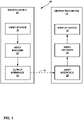
- FIG. 1 is a block diagram illustrating an example video encoding and decoding system 10 that may be configured to perform the techniques of this disclosure for motion vector prediction.
- system 10 includes a source device 12 that provides encoded video data to be decoded at a later time by a destination device 14.
- source device 12 provides the video data to destination device 14 via a computer-readable medium 16.
- Source device 12 and destination device 14 may comprise any of a wide range of devices, including desktop computers, notebook (i.e., laptop) computers, tablet computers, set-top boxes, telephone handsets such as so-called “smart” phones, so-called “smart” pads, televisions, cameras, display devices, digital media players, video gaming consoles, video streaming device, or the like.
- source device 12 and destination device 14 may be equipped for wireless communication.
- Computer-readable medium 16 may comprise any type of medium or device capable of moving the encoded video data from source device 12 to destination device 14.
- computer-readable medium 16 may comprise a communication medium to enable source device 12 to transmit encoded video data directly to destination device 14 in real-time.
- the encoded video data may be modulated according to a communication standard, such as a wireless communication protocol, and transmitted to destination device 14.
- the communication medium may comprise any wireless or wired communication medium, such as a radio frequency (RF) spectrum or one or more physical transmission lines.
- the communication medium may form part of a packet-based network, such as a local area network, a wide-area network, or a global network such as the Internet.
- the communication medium may include routers, switches, base stations, or any other equipment that may be useful to facilitate communication from source device 12 to destination device 14.
- encoded data may be output from output interface 22 to a storage device.
- encoded data may be accessed from the storage device by input interface.
- the storage device may include any of a variety of distributed or locally accessed data storage media such as a hard drive, Blu-ray discs, DVDs, CD-ROMs, flash memory, volatile or non-volatile memory, or any other suitable digital storage media for storing encoded video data.
- the storage device may correspond to a file server or another intermediate storage device that may store the encoded video generated by source device 12. Destination device 14 may access stored video data from the storage device via streaming or download.
- the file server may be any type of server capable of storing encoded video data and transmitting that encoded video data to the destination device 14.
- Example file servers include a web server (e.g., for a website), an FTP server, network attached storage (NAS) devices, or a local disk drive.
- Destination device 14 may access the encoded video data through any standard data connection, including an Internet connection. This may include a wireless channel (e.g., a Wi-Fi connection), a wired connection (e.g., DSL, cable modem, etc.), or a combination of both that is suitable for accessing encoded video data stored on a file server.
- the transmission of encoded video data from the storage device may be a streaming transmission, a download transmission, or a combination thereof.
- system 10 may be configured to support one-way or two-way video transmission to support applications such as video streaming, video playback, video broadcasting, and/or video telephony.
- source device 12 includes video source 18, video encoder 20, and output interface 22.
- Destination device 14 includes input interface 28, video decoder 30, and display device 32.
- video encoder 20 of source device 12 may be configured to apply the techniques of this disclosure for motion vector prediction.
- a source device and a destination device may include other components or arrangements.
- source device 12 may receive video data from an external video source 18, such as an external camera.
- destination device 14 may interface with an external display device, rather than including an integrated display device.
- the illustrated system 10 of FIG. 1 is merely one example.
- the techniques of this disclosure for motion vector prediction may be performed by any digital video encoding and/or decoding device. Although generally the techniques of this disclosure are performed by a video encoding device, the techniques may also be performed by a video encoder/decoder, typically referred to as a "CODEC.” Moreover, the techniques of this disclosure may also be performed by a video preprocessor.
- Source device 12 and destination device 14 are merely examples of such coding devices in which source device 12 generates coded video data for transmission to destination device 14. In some examples, devices 12, 14 may operate in a substantially symmetrical manner such that each of devices 12, 14 include video encoding and decoding components.
- system 10 may support one-way or two-way video transmission between video devices 12, 14, e.g., for video streaming, video playback, video broadcasting, or video telephony.
- Video source 18 of source device 12 may include a video capture device, such as a video camera, a video archive containing previously captured video, and/or a video feed interface to receive video from a video content provider.
- video source 18 may generate computer graphics-based data as the source video, or a combination of live video, archived video, and computer-generated video.
- source device 12 and destination device 14 may form so-called camera phones or video phones.
- the techniques described in this disclosure may be applicable to video coding in general, and may be applied to wireless and/or wired applications.
- the captured, pre-captured, or computer-generated video may be encoded by video encoder 20.
- the encoded video information may then be output by output interface 22 onto a computer-readable medium 16.
- Computer-readable medium 16 may include transient media, such as a wireless broadcast or wired network transmission, or storage media (that is, non-transitory storage media), such as a hard disk, flash drive, compact disc, digital video disc, Blu-ray disc, or other computer-readable media.
- a network server (not shown) may receive encoded video data from source device 12 and provide the encoded video data to destination device 14, e.g., via network transmission.
- a computing device of a medium production facility such as a disc stamping facility, may receive encoded video data from source device 12 and produce a disc containing the encoded video data. Therefore, computer-readable medium 16 may be understood to include one or more computer-readable media of various forms, in various examples.
- Input interface 28 of destination device 14 receives information from computer-readable medium 16.
- the information of computer-readable medium 16 may include syntax information defined by video encoder 20, which is also used by video decoder 30, that includes syntax elements that describe characteristics and/or processing of blocks and other coded units, e.g., GOPs.
- Display device 32 displays the decoded video data to a user, and may comprise any of a variety of display devices such as a cathode ray tube (CRT), a liquid crystal display (LCD), a plasma display, an organic light emitting diode (OLED) display, or another type of display device.
- CTR cathode ray tube
- LCD liquid crystal display
- plasma display e.g., a plasma display
- OLED organic light emitting diode
- Video encoder 20 and video decoder 30 may operate according to a video coding standard, such as the High Efficiency Video Coding (HEVC) standard, extensions to the HEVC standard, or subsequent standards, such as ITU-T H.266.
- video encoder 20 and video decoder 30 may also operate according to other proprietary or industry standards, such as the ITU-T H.264 standard, alternatively referred to as MPEG-4, Part 10, Advanced Video Coding (AVC), or extensions of such standards.
- the techniques of this disclosure are not limited to any particular coding standard.
- Other examples of video coding standards include MPEG-2 and ITU-T H.263.
- video encoder 20 and video decoder 30 may each be integrated with an audio encoder and decoder, and may include appropriate MUX-DEMUX units, or other hardware and software, to handle encoding of both audio and video in a common data stream or separate data streams. If applicable, MUX-DEMUX units may conform to the ITU H.223 multiplexer protocol, or other protocols such as the user datagram protocol (UDP).
- MUX-DEMUX units may conform to the ITU H.223 multiplexer protocol, or other protocols such as the user datagram protocol (UDP).
- Video encoder 20 and video decoder 30 each may be implemented as any of a variety of suitable encoder or decoder circuitry, such as one or more microprocessors, digital signal processors (DSPs), application specific integrated circuits (ASICs), field programmable gate arrays (FPGAs), discrete logic, software, hardware, firmware or any combinations thereof.
- DSPs digital signal processors
- ASICs application specific integrated circuits
- FPGAs field programmable gate arrays
- a device may store instructions for the software in a suitable, non-transitory computer-readable medium and execute the instructions in hardware using one or more processors to perform the techniques of this disclosure.
- Each of video encoder 20 and video decoder 30 may be included in one or more encoders or decoders, either of which may be integrated as part of a combined encoder/decoder (CODEC) in a respective device.
- CODEC combined encoder/decoder
- video encoder 20 and video decoder 30 may be configured to receive a current block of video data, construct a motion vector candidate list of merge candidates for the current block of video data based on motion information from a number of neighboring blocks relative to the current block, wherein the number of neighboring blocks considered for the motion vector candidate list is based on the size of the current block, and wherein the number of neighboring blocks is greater than 5, determine a current motion vector from the motion vector candidate list, and code (e.g., encode or decode) the current block of video data using the current motion vector.
- code e.g., encode or decode
- Video coding standards include ITU-T H.261, ISO/IEC MPEG-1 Visual, ITU-T H.262 or ISO/IEC MPEG-2 Visual, ITU-T H.263, ISO/IEC MPEG-4 Visual and ITU-T H.264 (also known as ISO/IEC MPEG-4 AVC), including its Scalable Video Coding (SVC) and Multiview Video Coding (MVC) extensions.
- SVC Scalable Video Coding
- MVC Multiview Video Coding
- HEVC High Efficiency Video Coding
- JCT-VC Joint Collaboration Team on Video Coding
- VCEG ITU-T Video Coding Experts Group
- MPEG ISO/IEC Motion Picture Experts Group
- a recent draft of HEVC is available from http://phenix.int-evry.fr/jct/doc_end_user/documents/12_Geneva/wg11/JCTVC-L1003-v34.zip.
- the HEVC standard is also presented jointly in Recommendation ITU-T H.265 and International Standard ISO/IEC 23008-2, both entitled “High efficiency video coding,” and both published October 2014.
- the JCT-VC developed the HEVC standard.
- the HEVC standardization efforts were based on an evolving model of a video coding device referred to as the HEVC Test Model (HM).
- HM presumed several additional capabilities of video coding devices relative to existing devices according to, e.g., ITU-T H.264/AVC.
- ITU-T H.264/AVC ITU-T H.264/AVC.
- H.264 provides nine intra-prediction encoding modes
- the HEVC HM may provide as many as thirty-three intra-prediction encoding modes.
- this disclosure may use some HEVC terminology for purposes of explanation, the techniques of this disclosure are not limited to HEVC, and in fact, it is explicitly contemplated that the techniques of this disclosure may be implemented in successor standards to HEVC.
- a video frame or picture may be divided into a sequence of treeblocks or largest coding units (LCU) that include both luma and chroma samples.
- Syntax data within a bitstream may define a size for the LCU, which is a largest coding unit in terms of the number of pixels.
- a slice includes a number of consecutive treeblocks in coding order.
- a video frame or picture may be partitioned into one or more slices.
- Each treeblock may be split into coding units (CUs) according to a quadtree.
- a quadtree data structure includes one node per CU, with a root node corresponding to the treeblock. If a CU is split into four sub-CUs, the node corresponding to the CU includes four leaf nodes, each of which corresponds to one of the sub-CUs.
- Each node of the quadtree data structure may provide syntax data for the corresponding CU.
- a node in the quadtree may include a split flag, indicating whether the CU corresponding to the node is split into sub-CUs.
- Syntax elements for a CU may be defined recursively, and may depend on whether the CU is split into sub-CUs. If a CU is not split further, it is referred as a leaf-CU.
- four sub-CUs of a leaf-CU will also be referred to as leaf-CUs even if there is no explicit splitting of the original leaf-CU. For example, if a CU at 16x16 size is not split further, the four 8x8 sub-CUs will also be referred to as leaf-CUs although the 16 ⁇ 16 CU was never split.
- a CU has a similar purpose as a macroblock of the H.264 standard, except that a CU does not have a size distinction.
- a treeblock may be split into four child nodes (also referred to as sub-CUs), and each child node may in turn be a parent node and be split into another four child nodes.
- Syntax data associated with a coded bitstream may define a maximum number of times a treeblock may be split, referred to as a maximum CU depth, and may also define a minimum size of the coding nodes.
- a bitstream may also define a smallest coding unit (SCU).
- SCU smallest coding unit
- This disclosure uses the term "block” to refer to any of a CU, PU, or TU, in the context of HEVC, or similar data structures in the context of other standards (e.g., macroblocks and sub-blocks thereof in H.264/AVC).
- a CU includes a coding node and prediction units (PUs) and transform units (TUs) associated with the coding node.
- a size of the CU corresponds to a size of the coding node and must be square in shape.
- the size of the CU may range from 8x8 pixels up to the size of the treeblock with a maximum of 64x64 pixels or greater.
- Each CU may contain one or more PUs and one or more TUs.
- Syntax data associated with a CU may describe, for example, partitioning of the CU into one or more PUs. Partitioning modes may differ between whether the CU is skip or direct mode encoded, intra-prediction mode encoded, or inter-prediction mode encoded.
- PUs may be partitioned to be non-square in shape.
- Syntax data associated with a CU may also describe, for example, partitioning of the CU into one or more TUs according to a quadtree.
- a TU can be square or non-square (e.
- the HEVC standard allows for transformations according to TUs, which may be different for different CUs.
- the TUs are typically sized based on the size of PUs within a given CU defined for a partitioned LCU, although this may not always be the case.
- the TUs are typically the same size or smaller than the PUs.
- residual samples corresponding to a CU may be subdivided into smaller units using a quadtree structure known as "residual quad tree" (RQT).
- RQT residual quadtree structure
- the leaf nodes of the RQT may be referred to as transform units (TUs).
- Pixel difference values associated with the TUs may be transformed to produce transform coefficients, which may be quantized.
- a leaf-CU may include one or more prediction units (PUs).
- a PU represents a spatial area corresponding to all or a portion of the corresponding CU, and may include data for retrieving a reference sample for the PU.
- a PU includes data related to prediction. For example, when the PU is intra-mode encoded, data for the PU may be included in a residual quadtree (RQT), which may include data describing an intra-prediction mode for a TU corresponding to the PU.
- RQT residual quadtree
- the PU may include data defining one or more motion vectors for the PU.
- the data defining the motion vector for a PU may describe, for example, a horizontal component of the motion vector, a vertical component of the motion vector, a resolution for the motion vector (e.g., one-quarter pixel precision or one-eighth pixel precision), a reference picture to which the motion vector points, and/or a reference picture list (e.g., List 0, List 1, or List C) for the motion vector.
- a horizontal component of the motion vector e.g., a vertical component of the motion vector
- a resolution for the motion vector e.g., one-quarter pixel precision or one-eighth pixel precision
- a reference picture to which the motion vector points e.g., List 0, List 1, or List C
- a leaf-CU having one or more PUs may also include one or more transform units (TUs).
- the transform units may be specified using an RQT (also referred to as a TU quadtree structure), as discussed above.
- RQT also referred to as a TU quadtree structure
- a split flag may indicate whether a leaf-CU is split into four transform units. Then, each transform unit may be split further into further sub-TUs. When a TU is not split further, it may be referred to as a leaf-TU.
- all the leaf-TUs belonging to a leaf-CU share the same intra-prediction mode. That is, the same intra-prediction mode is generally applied to calculate predicted values for all TUs of a leaf-CU.
- a video encoder may calculate a residual value for each leaf-TU using the intra-prediction mode, as a difference between the portion of the CU corresponding to the TU and the original block.
- a TU is not necessarily limited to the size of a PU. Thus, TUs may be larger or smaller than a PU.
- a PU may be collocated with a corresponding leaf-TU for the same CU. In some examples, the maximum size of a leaf-TU may correspond to the size of the corresponding leaf-CU.
- TUs of leaf-CUs may also be associated with respective quadtree data structures, referred to as residual quadtrees (RQTs). That is, a leaf-CU may include a quadtree indicating how the leaf-CU is partitioned into TUs.
- the root node of a TU quadtree generally corresponds to a leaf-CU, while the root node of a CU quadtree generally corresponds to a treeblock (or LCU).
- TUs of the RQT that are not split are referred to as leaf-TUs.
- this disclosure uses the terms CU and TU to refer to leaf-CU and leaf-TU, respectively, unless noted otherwise.
- a video sequence typically includes a series of video frames or pictures.
- a group of pictures generally comprises a series of one or more of the video pictures.
- a GOP may include syntax data in a header of the GOP, a header of one or more of the pictures, or elsewhere, that describes a number of pictures included in the GOP.
- Each slice of a picture may include slice syntax data that describes an encoding mode for the respective slice.
- Video encoder 20 typically operates on video blocks within individual video slices in order to encode the video data.
- a video block may correspond to a coding node within a CU.
- the video blocks may have fixed or varying sizes, and may differ in size according to a specified coding standard.
- the HM supports prediction in various PU sizes. Assuming that the size of a particular CU is 2Nx2N, the HM supports intra-prediction in PU sizes of 2Nx2N or NxN, and inter-prediction in symmetric PU sizes of 2Nx2N, 2NxN, Nx2N, or NxN. The HM also supports asymmetric partitioning for inter-prediction in PU sizes of 2NxnU, 2NxnD, nLx2N, and nRx2N. In asymmetric partitioning, one direction of a CU is not partitioned, while the other direction is partitioned into 25% and 75%.
- 2NxnU refers to a 2Nx2N CU that is partitioned horizontally with a 2Nx0.5N PU on top and a 2Nx1.5N PU on bottom.
- NxN and “N by N” may be used interchangeably to refer to the pixel dimensions of a video block in terms of vertical and horizontal dimensions, e.g., 16x16 pixels or 16 by 16 pixels.
- an NxN block generally has N pixels in a vertical direction and N pixels in a horizontal direction, where N represents a nonnegative integer value.
- the pixels in a block may be arranged in rows and columns.
- blocks need not necessarily have the same number of pixels in the horizontal direction as in the vertical direction.
- blocks may comprise NxM pixels, where M is not necessarily equal to N.
- video encoder 20 may calculate residual data for the TUs of the CU.
- the PUs may comprise syntax data describing a method or mode of generating predictive pixel data in the spatial domain (also referred to as the pixel domain) and the TUs may comprise coefficients in the transform domain following application of a transform, e.g., a discrete cosine transform (DCT), an integer transform, a wavelet transform, or a conceptually similar transform to residual video data.
- the residual data may correspond to pixel differences between pixels of the unencoded picture and prediction values corresponding to the PUs.
- Video encoder 20 may form the TUs including the residual data for the CU, and then transform the TUs to produce transform coefficients for the CU.
- video encoder 20 may perform quantization of the transform coefficients.
- Quantization generally refers to a process in which transform coefficients are quantized to possibly reduce the amount of data used to represent the coefficients, providing further compression.
- the quantization process may reduce the bit depth associated with some or all of the coefficients. For example, an n-bit value may be rounded down to an m-bit value during quantization, where n is greater than m.
- the video encoder may scan the transform coefficients, producing a one-dimensional vector from the two-dimensional matrix including the quantized transform coefficients.
- the scan may be designed to place higher energy (and therefore lower frequency) coefficients at the front of the array and to place lower energy (and therefore higher frequency) coefficients at the back of the array.
- video encoder 20 may utilize a predefined scan order to scan the quantized transform coefficients to produce a serialized vector that can be entropy encoded.
- video encoder 20 may perform an adaptive scan.
- video encoder 20 may entropy encode the one-dimensional vector, e.g., according to context-adaptive variable length coding (CAVLC), context-adaptive binary arithmetic coding (CABAC), syntax-based context-adaptive binary arithmetic coding (SBAC), Probability Interval Partitioning Entropy (PIPE) coding or another entropy encoding methodology.
- Video encoder 20 may also entropy encode syntax elements associated with the encoded video data for use by video decoder 30 in decoding the video data.
- video encoder 20 may assign a context within a context model to a symbol to be transmitted.
- the context may relate to, for example, whether neighboring values of the symbol are non-zero or not.
- video encoder 20 may select a variable length code for a symbol to be transmitted. Codewords in VLC may be constructed such that relatively shorter codes correspond to more probable symbols, while longer codes correspond to less probable symbols. In this way, the use of VLC may achieve a bit savings over, for example, using equal-length codewords for each symbol to be transmitted.
- the probability determination may be based on a context assigned to the symbol.
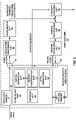
- FIG. 2 is a block diagram illustrating an example of video encoder 20 that may be configured to perform the techniques of this disclosure for motion vector prediction, as will be explained in more detail below.
- Video encoder 20 may perform intra- and inter-coding of video blocks within video slices.
- Intra-coding relies on spatial prediction to reduce or remove spatial redundancy in video within a given video frame or picture.
- Inter-coding relies on temporal prediction to reduce or remove temporal redundancy in video within adjacent frames or pictures of a video sequence.
- Intra-mode (I mode) may refer to any of several spatial based coding modes.
- Inter-modes, such as uni-directional prediction (P mode) or bi-prediction (B mode) may refer to any of several temporal-based coding modes.
- video encoder 20 receives a current video block within a video frame to be encoded.
- video encoder 20 includes video data memory 41, mode select unit 40, reference picture memory 64, summer 50, transform processing unit 52, quantization unit 54, and entropy encoding unit 56.
- Mode select unit 40 includes motion compensation unit 44, motion estimation unit 42, intra-prediction unit 46, and partition unit 48.
- video encoder 20 also includes inverse quantization unit 58, inverse transform unit 60, and summer 62.
- a deblocking filter (not shown in FIG. 2 ) may also be included to filter block boundaries to remove blockiness artifacts from reconstructed video.
- the deblocking filter would typically filter the output of summer 62. Additional filters (in loop or post loop) may also be used in addition to the deblocking filter. Such filters are not shown for brevity, but if desired, may filter the output of summer 50 (as an in-loop filter).
- Video data memory 41 may be configured to store video data to be encoded by the components of video encoder 20.
- the video data stored in video data memory 41 may be obtained, for example, from video source 18.
- Reference picture memory 64 (sometimes called a decoded picture buffer) may be a reference picture memory that stores reference video data for use in encoding video data by video encoder 20, e.g., in intra- or inter-coding modes.
- Video data memory 41 and reference picture memory 64 may be formed by any of a variety of memory devices, such as dynamic random access memory (DRAM), including synchronous DRAM (SDRAM), magnetoresistive RAM (MRAM), resistive RAM (RRAM), or other types of memory devices.
- Video data memory 41 and reference picture memory 64 may be provided by the same memory device or separate memory devices.
- video data memory 41 may be on-chip with other components of video encoder 20, or off-chip relative to those components.
- video encoder 20 receives a video frame or slice to be coded.
- the frame or slice may be divided into multiple video blocks.
- Motion estimation unit 42 and motion compensation unit 44 perform inter-predictive coding of the received video block relative to one or more blocks in one or more reference frames to provide temporal prediction.
- Intra-prediction unit 46 may alternatively perform intra-predictive coding of the received video block relative to one or more neighboring blocks in the same frame or slice as the block to be coded to provide spatial prediction.
- Video encoder 20 may perform multiple coding passes, e.g., to select an appropriate coding mode for each block of video data.
- partition unit 48 may partition blocks of video data into sub-blocks, based on evaluation of previous partitioning schemes in previous coding passes. For example, partition unit 48 may initially partition a frame or slice into LCUs, and partition each of the LCUs into sub-CUs based on rate-distortion analysis (e.g., rate-distortion optimization). Mode select unit 40 may further produce a quadtree data structure indicative of partitioning of an LCU into sub-CUs. Leaf-node CUs of the quadtree may include one or more PUs and one or more TUs.
- Mode select unit 40 may select one of the coding modes, intra or inter, e.g., based on error results, and provides the resulting intra- or inter-coded block to summer 50 to generate residual block data and to summer 62 to reconstruct the encoded block for use as a reference frame. Mode select unit 40 also provides syntax elements, such as motion vectors, intra-mode indicators, partition information, and other such syntax information, to entropy encoding unit 56.
- Motion estimation unit 42 and motion compensation unit 44 may be highly integrated, but are illustrated separately for conceptual purposes.
- Motion estimation performed by motion estimation unit 42, is the process of generating motion vectors, which estimate motion for video blocks.
- a motion vector for example, may indicate the displacement of a PU of a video block within a current video frame or picture relative to a predictive block within a reference frame (or other coded unit) relative to the current block being coded within the current frame (or other coded unit).
- a predictive block is a block that is found to closely match the block to be coded, in terms of pixel difference, which may be determined by sum of absolute difference (SAD), sum of square difference (SSD), or other difference metrics.
- video encoder 20 may calculate values for sub-integer pixel positions of reference pictures stored in reference picture memory 64. For example, video encoder 20 may interpolate values of one-quarter pixel positions, one-eighth pixel positions, or other fractional pixel positions of the reference picture. Therefore, motion estimation unit 42 may perform a motion search relative to the full pixel positions and fractional pixel positions and output a motion vector with fractional pixel precision.
- Motion estimation unit 42 calculates a motion vector for a PU of a video block in an inter-coded slice by comparing the position of the PU to the position of a predictive block of a reference picture.
- the reference picture may be selected from a first reference picture list (List 0) or a second reference picture list (List 1), each of which identify one or more reference pictures stored in reference picture memory 64.
- Motion estimation unit 42 sends the calculated motion vector to entropy encoding unit 56 and motion compensation unit 44.
- Motion compensation performed by motion compensation unit 44, may involve fetching or generating the predictive block based on the motion vector determined by motion estimation unit 42. Again, motion estimation unit 42 and motion compensation unit 44 may be functionally integrated, in some examples. Upon receiving the motion vector for the PU of the current video block, motion compensation unit 44 may locate the predictive block to which the motion vector points in one of the reference picture lists. Summer 50 forms a residual video block by subtracting pixel values of the predictive block from the pixel values of the current video block being coded, forming pixel difference values, as discussed below. In general, motion estimation unit 42 performs motion estimation relative to luma components, and motion compensation unit 44 uses motion vectors calculated based on the luma components for both chroma components and luma components. Mode select unit 40 may also generate syntax elements associated with the video blocks and the video slice for use by video decoder 30 in decoding the video blocks of the video slice.
- Video encoder 20, including motion estimation unit 42 and motion compensation unit 44 may be configured to perform any of the various techniques of this disclosure discussed above with respect to FIG. 1 , and as will be described in more detail below.
- motion compensation unit 44 may be configured to code motion information for a block of video data using AMVP or merge mode in accordance with the techniques of this disclosure.
- video encoder 20, including motion estimation unit 42 and motion compensation unit 44 may be configured to perform any combination of the motion vector candidate list construction techniques of this disclosure which are described in more detail below.
- the terms motion vector candidate list, merge candidate list, and candidate list may be used interchangeably.
- motion compensation unit 44 may form a candidate list including a set of merge candidates. Motion compensation unit 44 may add candidates to the candidate list based on a particular, predetermined order. In other example of the disclosure, motion compensation unit 44 may be configured to add candidates to the candidate list in dynamically different orders, based on histogram information of motion vectors from neighboring blocks. Motion compensation unit 44 may also add additional candidates and perform pruning of the candidate list, as discussed in more detail below.
- mode select unit 40 may determine which of the candidates is to be used to encode motion information of the current block, and encode a merge index representing the selected candidate.
- Intra-prediction unit 46 may intra-predict a current block, as an alternative to the inter-prediction performed by motion estimation unit 42 and motion compensation unit 44, as described above. In particular, intra-prediction unit 46 may determine an intra-prediction mode to use to encode a current block. In some examples, intra-prediction unit 46 may encode a current block using various intra-prediction modes, e.g., during separate encoding passes, and intra-prediction unit 46 (or mode select unit 40, in some examples) may select an appropriate intra-prediction mode to use from the tested modes.
- intra-prediction unit 46 may calculate rate-distortion values using a rate-distortion analysis for the various tested intra-prediction modes, and select the intra-prediction mode having the best rate-distortion characteristics among the tested modes.
- Rate-distortion analysis generally determines an amount of distortion (or error) between an encoded block and an original, unencoded block that was encoded to produce the encoded block, as well as a bitrate (that is, a number of bits) used to produce the encoded block.
- Intra-prediction unit 46 may calculate ratios from the distortions and rates for the various encoded blocks to determine which intra-prediction mode exhibits the best rate-distortion value for the block.
- intra-prediction unit 46 may provide information indicative of the selected intra-prediction mode for the block to entropy encoding unit 56.
- Entropy encoding unit 56 may encode the information indicating the selected intra-prediction mode.
- Video encoder 20 may include in the transmitted bitstream configuration data, which may include a plurality of intra-prediction mode index tables and a plurality of modified intra-prediction mode index tables (also referred to as codeword mapping tables), definitions of encoding contexts for various blocks, and indications of a most probable intra-prediction mode, an intra-prediction mode index table, and a modified intra-prediction mode index table to use for each of the contexts.
- Video encoder 20 forms a residual video block by subtracting the prediction data from mode select unit 40 from the original video block being coded.
- Summer 50 represents the component or components that perform this subtraction operation.
- Transform processing unit 52 applies a transform, such as a discrete cosine transform (DCT) or a conceptually similar transform, to the residual block, producing a video block comprising residual transform coefficient values.
- Transform processing unit 52 may perform other transforms which are conceptually similar to DCT. Wavelet transforms, integer transforms, sub-band transforms or other types of transforms could also be used.
- transform processing unit 52 applies the transform to the residual block, producing a block of residual transform coefficients.
- the transform may convert the residual information from a pixel value domain to a transform domain, such as a frequency domain.
- Transform processing unit 52 may send the resulting transform coefficients to quantization unit 54.
- Quantization unit 54 quantizes the transform coefficients to further reduce bit rate. The quantization process may reduce the bit depth associated with some or all of the coefficients. The degree of quantization may be modified by adjusting a quantization parameter.
- quantization unit 54 may then perform a scan of the matrix including the quantized transform coefficients.
- entropy encoding unit 56 may perform the scan.
- entropy encoding unit 56 entropy codes the quantized transform coefficients.
- entropy encoding unit 56 may perform context adaptive variable length coding (CAVLC), context adaptive binary arithmetic coding (CABAC), syntax-based context-adaptive binary arithmetic coding (SBAC), probability interval partitioning entropy (PIPE) coding or another entropy coding technique.
- context may be based on neighboring blocks.
- the encoded bitstream may be transmitted to another device (e.g., video decoder 30) or archived for later transmission or retrieval.
- Inverse quantization unit 58 and inverse transform unit 60 apply inverse quantization and inverse transformation, respectively, to reconstruct the residual block in the pixel domain, e.g., for later use as a reference block.
- Motion compensation unit 44 may calculate a reference block by adding the residual block to a predictive block of one of the frames of reference picture memory 64. Motion compensation unit 44 may also apply one or more interpolation filters to the reconstructed residual block to calculate sub-integer pixel values for use in motion estimation.
- Summer 62 adds the reconstructed residual block to the motion compensated prediction block produced by motion compensation unit 44 to produce a reconstructed video block for storage in reference picture memory 64.
- the reconstructed video block may be used by motion estimation unit 42 and motion compensation unit 44 as a reference block to inter-code a block in a subsequent video frame.
- video encoder 20 of FIG. 2 represents an example of a video coder configured to derive a histogram of motion vector information from neighboring blocks relative to a current block, determine merge candidates for a motion vector candidate list for motion vector prediction for the current block based on the derived histogram, order the motion vector candidate list based on the derived histogram, and perform merge vector prediction using the motion vector candidate list.
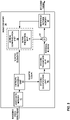
- FIG. 3 is a block diagram illustrating an example of video decoder 30 that may be configured to perform the motion vector prediction techniques of this disclosure.
- video decoder 30 includes video data memory 71, entropy decoding unit 70, motion compensation unit 72, intra-prediction unit 74, inverse quantization unit 76, inverse transformation unit 78, reference picture memory 82 and summer 80.
- Video decoder 30 may, in some examples, perform a decoding pass generally reciprocal to the encoding pass described with respect to video encoder 20 ( FIG. 2 ).
- Motion compensation unit 72 may generate prediction data based on motion vectors received from entropy decoding unit 70
- intra-prediction unit 74 may generate prediction data based on intra-prediction mode indicators received from entropy decoding unit 70.
- Video data memory 71 may store encoded video data, such as an encoded video bitstream, to be decoded by the components of video decoder 30.
- the video data stored in video data memory 71 may be obtained, for example, from computer-readable medium 16, e.g., from a local video source, such as a camera, via wired or wireless network communication of video data, or by accessing physical data storage media.
- Video data memory 71 may form a coded picture buffer (CPB) that stores encoded video data from an encoded video bitstream.
- CPB coded picture buffer
- Reference picture memory 82 may be a reference picture memory that stores reference video data for use in decoding video data by video decoder 30, e.g., in intra- or inter-coding modes, or for output.
- Video data memory 71 and reference picture memory 82 may be formed by any of a variety of memory devices, such as DRAM, SDRAM, MRAM, RRAM, or other types of memory devices.
- Video data memory 71 and reference picture memory 82 may be provided by the same memory device or separate memory devices.
- video data memory 71 may be on-chip with other components of video decoder 30, or off-chip relative to those components.
- video decoder 30 receives an encoded video bitstream that represents video blocks of an encoded video slice and associated syntax elements from video encoder 20.
- Entropy decoding unit 70 of video decoder 30 entropy decodes the bitstream to generate quantized coefficients, motion vectors or intra-prediction mode indicators, and other syntax elements.
- Entropy decoding unit 70 forwards the motion vectors to and other syntax elements to motion compensation unit 72.
- Video decoder 30 may receive the syntax elements at the video slice level and/or the video block level.
- intra-prediction unit 74 may generate prediction data for a video block of the current video slice based on a signaled intra-prediction mode and data from previously decoded blocks of the current frame or picture.
- motion compensation unit 72 produces predictive blocks for a video block of the current video slice based on the motion vectors and other syntax elements received from entropy decoding unit 70.
- the predictive blocks may be produced from one of the reference pictures within one of the reference picture lists.
- Video decoder 30 may construct the reference frame lists, List 0 and List 1, using default construction techniques based on reference pictures stored in reference picture memory 82.
- Motion compensation unit 72 determines prediction information for a video block of the current video slice by parsing the motion vectors and other syntax elements, and uses the prediction information to produce the predictive blocks for the current video block being decoded. For example, motion compensation unit 72 uses some of the received syntax elements to determine a prediction mode (e.g., intra- or inter-prediction) used to code the video blocks of the video slice, an inter-prediction slice type (e.g., B slice or P slice), construction information for one or more of the reference picture lists for the slice, motion vectors for each inter-encoded video block of the slice, inter-prediction status for each inter-coded video block of the slice, and other information to decode the video blocks in the current video slice.
- a prediction mode e.g., intra- or inter-prediction
- an inter-prediction slice type e.g., B slice or P slice
- construction information for one or more of the reference picture lists for the slice motion vectors for each inter-encoded video block of the slice, inter-prediction status
- Motion compensation unit 72 may also perform interpolation based on interpolation filters. Motion compensation unit 72 may use interpolation filters as used by video encoder 20 during encoding of the video blocks to calculate interpolated values for sub-integer pixels of reference blocks. In this case, motion compensation unit 72 may determine the interpolation filters used by video encoder 20 from the received syntax elements and use the interpolation filters to produce predictive blocks.
- Video decoder 30, including motion compensation unit 72 may be configured to perform any of the various techniques of this disclosure discussed above with respect to FIG. 1 , and as will be discussed in more detail below.
- motion compensation unit 72 may be configured to perform motion vector prediction using AMVP or merge mode in accordance with the techniques of this disclosure.
- video decoder 30, including motion compensation unit 72 may be configured to perform any combination of the motion vector candidate list construction techniques of this disclosure which are described in more detail below.
- Entropy decoding unit 70 may decode one or more syntax elements representing how motion information is coded for the current block.
- motion compensation unit 72 may form a candidate list including a set of merge candidates. Motion compensation unit 72 may add candidates to the candidate list based on a particular, predetermined order. In other example of the disclosure, motion compensation unit 72 may be configured to add candidates to the candidate list in dynamically different orders, based on histogram information of motion vectors from neighboring blocks. Motion compensation unit 72 may also add additional candidates and perform pruning of the candidate list, as discussed in more detail below. Ultimately, motion compensation unit 72 may decode a merge index representing which of the candidates is used to code motion information for the current block.
- Inverse quantization unit 76 inverse quantizes, i.e., de-quantizes, quantized transform coefficients provided in the bitstream and entropy decoded by entropy decoding unit 70.
- the inverse quantization process may include use of a quantization parameter QP Y calculated by video decoder 30 for each video block in the video slice to determine a degree of quantization and, likewise, a degree of inverse quantization that should be applied.
- Inverse transform unit 78 applies an inverse transform, e.g., an inverse DCT, an inverse integer transform, or a conceptually similar inverse transform process, to the transform coefficients in order to produce residual blocks in the pixel domain.
- an inverse transform e.g., an inverse DCT, an inverse integer transform, or a conceptually similar inverse transform process
- video decoder 30 forms a decoded video block by summing the residual blocks from inverse transform unit 78 with the corresponding predictive blocks generated by motion compensation unit 72.
- Summer 80 represents the component or components that perform this summation operation.
- a deblocking filter may also be applied to filter the decoded blocks in order to remove blockiness artifacts.
- Other loop filters may also be used to smooth pixel transitions, or otherwise improve the video quality.
- the decoded video blocks in a given frame or picture are then stored in reference picture memory 82, which stores reference pictures used for subsequent motion compensation.
- Reference picture memory 82 also stores decoded video for later presentation on a display device, such as display device 32 of FIG. 1 .
- video decoder 30 represents an example of a video coder configured to derive a histogram of motion vector information from neighboring blocks relative to a current block, determine merge candidates for a motion vector candidate list for motion vector prediction for the current block based on the derived histogram, order the motion vector candidate list based on the derived histogram, and perform merge vector prediction using the motion vector candidate list.
- forward and backward prediction directions are two prediction directions corresponding to reference picture list 0 (RefPicList0) and reference picture list 1 (RefPicList1) of a current picture or slice.
- Forward and backward do not necessarily have a geometric meaning. Instead, they are used to distinguish which reference picture list a motion vector is based on.
- Forward prediction means the prediction formed based on reference list 0
- backward prediction means the prediction formed based on reference list 1. In case both reference list 0 and reference list 1 are used to form a prediction for a given block, it is called bi-directional prediction.
- every block inside the picture or slice is forward predicted. If both reference picture lists are used for a given picture or slice, a block inside the picture or slice may be forward predicted, backward predicted, or bi-directionally predicted.
- the motion information also includes a reference index and a motion vector.
- a reference index is used to identify a reference picture in a corresponding reference picture list (e.g. RefPicList0 or RefPicList1).
- a motion vector has both a horizontal and a vertical component, with each component indicating an offset value along horizontal and vertical direction, respectively.
- the motion vector indicates the position of the predictor block relative to the position of the current block being coded.
- the reference index indicates the picture that contains the predictor block.
- the term "motion vector" may be used interchangeably with motion information, to indicate both the motion vector and its associated reference index.
- Picture order count is widely used in video coding standards to identify a display order of a picture. Although there are cases in which two pictures within one coded video sequence may have the same POC value, it typically does not happen within a coded video sequence. When multiple coded video sequences are present in a bitstream, pictures with a same value of POC may be closer to each other in terms of decoding order. POC values of pictures are typically used for reference picture list construction, derivation of reference picture sets as in HEVC and motion vector scaling.
- each inter macroblock (MB) (e.g., a MB coded using inter-prediction) may be partitioned in four different ways:
- Different MB partitions in one MB may have different reference index values for each prediction direction (RefPicList0 or RefPicList1).
- RefPicList0 or RefPicList1 When an MB is not partitioned into four 8 ⁇ 8 MB partitions, the MB has only one motion vector for each MB partition in each prediction direction.
- each 8 ⁇ 8 MB partition can be further partitioned into sub-blocks, each of which can have a different motion vector in each prediction direction.
- sub-blocks There are four different ways to divide an 8 ⁇ 8 MB partitions into sub-blocks:
- Each sub-block may have a different motion vector in each prediction direction. Therefore, a motion vector is present in a level equal to or higher than the sub-block.
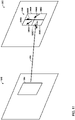
- Temporal direct mode in AVC will no be described.
- temporal direct mode may be enabled at either the MB level or the MB partition level for skip or direct mode in B slices.
- the motion vectors of the block co-located with the current MB partition in the RefPicList1[0] of the current block are used to derive the motion vectors.
- Each motion vector in the co-located block is scaled based on POC distances.
- a direct mode can also predict motion information from the spatial neighbors.
- coding tree block CTB
- CTU coding tree unit
- a CTB contains a quad-tree the nodes of which are coding units.
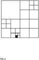
- a CTB may be recursively split into CUs in a quad-tree manner, as described in W. J. Han et al, "Improved Video Compression Efficiency Through Flexible Unit Representation and Corresponding Extension of Coding Tools," IEEE Transaction on Circuits and Systems for Video Technology, vol. 20, no. 12, pp. 1709-1720, Dec. 2010 , and shown in FIG. 4 .
- each level of partitioning is a quad-tree split into four sub-blocks.
- the black block is an example of a leaf-node (i.e., a block that is not further split).
- the size of a CTB can range from 16x16 to 64x64 in the HEVC main profile (although technically 8x8 CTB sizes can be supported).
- a CU could be the same size of a CTB although and as small as 8x8.
- Each CU is coded with one mode (e.g., an intra-prediction mode or an inter prediction mode).
- the CU may be further partitioned into 2 or 4 prediction units (PUs) or become just one PU when further partition isn't applied.
- the PUs can be half size rectangles or two rectangles that are 1 ⁇ 4 or 3 ⁇ 4 the size of the CU.
- each PU When the CU is inter coded, one set of motion information (e.g., motion vector, prediction direction, and reference picture) is present for each PU.
- each PU is coded with a unique inter-prediction mode to derive the set of motion information.
- a unique inter-prediction mode to derive the set of motion information.
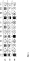
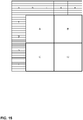
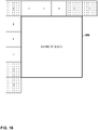
- a CU coded with inter prediction mode there are eight partition modes for a CU coded with inter prediction mode, i.e., PART_2Nx2N, PART_2NxN, PART_Nx2N, PART_NxN, PART_2NxnU, PART_2NxnD, PART_nLx2N and PART_nRx2N, as shown in FIG. 5 .
- a CU coded with partition mode PART_2Nx2N is not further split. That is, the entire CU is treated as a single PU (PU0).
- a CU coded with partition mode PART_2NxN is symmetrically horizontally split into two PUs (PU0 and PU1).
- a CU coded with partition mode PART_Nx2N is symmetrically vertically split into two PUs.
- a CU coded with partition mode PART_NxN is symmetrically split into four equal-sized PUs (PU0, PU1, PU2, PU3).
- a CU coded with partition mode PART_2NxnU is asymmetrically horizontally split into one PUO (the upper PU) having 1 ⁇ 4 the size of the CU and one PU1 (the lower PU) having 3 ⁇ 4 the size of the CU.
- a CU coded with partition mode PART_2NxnD is asymmetrically horizontally split into one PUO (the upper PU) having 3 ⁇ 4 the size of the CU and one PU1 (the lower PU) having 1 ⁇ 4 the size of the CU.
- a CU coded with partition mode PART_nLx2N is asymmetrically vertically split into one PUO (the left PU) having 1 ⁇ 4 the size of the CU and one PU1 (the right PU) having 3 ⁇ 4 the size of the CU.
- a CU coded with partition mode PART_nRx2N is asymmetrically vertically split into one PUO (the left PU) having 3 ⁇ 4 the size of the CU and one PU1 (the right PU) having 1 ⁇ 4 the size of the CU.
- HEVC uses a quadtree partitioning structure
- other partitioning structure are being studied for future video coding standards.
- VCEG proposal COM16-C966 quad-tree-binary-tree partitioning techniques
- a CTB is first partitioned using quad-tree portioning techniques, where the quad-tree splitting of one node can be iterated until the node reaches the minimum allowed quad-tree leaf node size.
- the minimum allowed quad-tree leaf node size may be indicated to video decoder by the value of the syntax element MinQTSize. If the quad-tree leaf node size is not larger than the maximum allowed binary-tree root node size (e.g., as denoted by a syntax element MaxBTSize), the quad-tree leaf node can be further partitioned using binary-tree partitioning.
- the binary-tree partitioning of one node can be iterated until the node reaches the minimum allowed binary-tree leaf node size (e.g., as denoted by a syntax element MinBTSize) or the maximum allowed binary-tree depth (e.g., as denoted by a syntax element MaxBTDepth).
- VCEG proposal COM16-C966 uses the term "CU" to refer to binary-tree leaf nodes.
- CUs are used for prediction (e.g., intra-prediction, inter prediction, etc.) and transform without any further partitioning.
- there are two splitting types for binary-tree splitting there are two splitting types for binary-tree splitting: symmetric horizontal splitting and symmetric vertical splitting. In each case, a block is split by dividing the block down the middle, either horizontally or vertically.
- the CTU size is set as 128x128 (e.g., a 128x128 luma block and two corresponding 64x64 chroma blocks), the MinQTSize is set as 16x16, the MaxBTSize is set as 64x64, the MinBTSize (for both width and height) is set as 4, and the MaxBTDepth is set as 4.
- the quad-tree partitioning is applied to the CTU first to generate quad-tree leaf nodes.
- the quad-tree leaf nodes may have a size from 16x16 (i.e., the MinQTSize is 16x16) to 128x128 (i.e., the CTU size).
- the leaf quad-tree node if the leaf quad-tree node is 128x128, the leaf quad-tree node cannot be further split by the binary-tree since the size of the leaf quad-tree node exceeds the MaxBTSize (i.e., 64x64). Otherwise, the leaf quad-tree node is further partitioned by the binary-tree. Therefore, the quad-tree leaf node is also the root node for the binary-tree and has the binary-tree depth as 0.
- the binary-tree depth reaching MaxBTDepth e.g., 4) implies that there is no further splitting.
- the binary-tree node having a width equal to the MinBTSize (e.g., 4) implies that there is no further horizontal splitting.
- the binary-tree node having a height equal to MinBTSize implies no further vertical splitting.
- the leaf nodes of the binary-tree (CUs) are further processed (e.g., by performing a prediction process and a transform process) without any further partitioning.
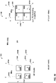
- FIG. 6A illustrates an example of a block 150 (e.g., a CTB) partitioned using QTBT partitioning techniques.
- a block 150 e.g., a CTB partitioned using QTBT partitioning techniques.
- FIG. 6A using QTBT partition techniques, each of the resultant blocks is split symmetrically through the center of each block.
- FIG. 6B illustrates the tree structure corresponding to the block partitioning of FIG. 6A .
- the solid lines in FIG. 6B indicate quad-tree splitting and dotted lines indicate binary-tree splitting.
- a syntax element e.g., a flag
- the type of splitting performed e.g., horizontal or vertical
- 0 indicates horizontal splitting
- 1 indicates vertical splitting.
- quad-tree splitting there is no need to indicate the splitting type, as quad-tree splitting always splits a block horizontally and vertically into 4 sub-blocks with an equal size.
- block 150 is split into the four blocks 151, 152, 153, and 154, shown in FIG. 6A , using QT partitioning.
- Block 154 is not further split, and is therefore a leaf node.
- block 151 is further split into two blocks using BT partitioning.
- node 172 is marked with a 1, indicating vertical splitting.
- the splitting at node 172 results in block 157 and the block including both blocks 155 and 156.
- Blocks 155 and 156 are created by a further vertical splitting at node 174.
- block 152 is further split into two blocks 158 and 159 using BT partitioning.
- node 176 is marked with a 1, indicating horizontal splitting.
- block 153 is split into 4 equal size blocks using QT partitioning. Blocks 163 and 166 are created from this QT partitioning and are not further split.
- the upper left block is first split using vertical binary-tree splitting resulting in block 160 and a right vertical block.
- the right vertical block is then split using horizontal binary-tree splitting into blocks 161 and 162.
- the lower right block created from the quad-tree splitting at node 178 is split at node 184 using horizontal binary-tree splitting into blocks 164 and 165.
- the motion vector candidate list construction techniques may be used in conjunction with any video block partitioning techniques, including the MB partitioning structure of H.264/AVC, the quadtree partitioning structure of HEVC, or a QTBT partitioning structure, such as the QTBT structure proposed for H.266.
- motion vector prediction in HEVC will now be described.
- merge mode skip is considered as a special case of merge
- AMVP advanced motion vector prediction
- video encoder 20 and video decoder 30 are configured to construct a motion vector (MV) candidate list for multiple motion vector predictors.
- a motion vector predictor may be a motion vector from a neighboring block, or an artificially generated motion vector, that may be used to predict the motion vector for a currently coded block of the video data.
- video encoder 20 selects one motion vector from the motion vector candidate list, as well as the reference index associated with that candidate, and uses that candidate motion vector for inter prediction.
- Video encoder 20 may signal an index (e.g., merge index) of the selected motion vector candidate to video decoder 30.
- Video decoder 30 may construct the motion vector candidate list for merge mode in the same manner as video encoder 20.
- Video decoder 30 may use the signaled index into the motion vector candidate list to identify the selected candidate, and then retrieve the motion vector and reference index associated with that candidate to use as the motion vector for the current block.
- the MV candidate list contains up to 5 candidates for the merge mode and two candidates for the AMVP mode.
- a merge candidate may contain a set of motion information, e.g., motion vectors corresponding to both reference picture lists (list 0 and list 1) and the reference indices. If a merge candidate is identified by a merge index, the reference pictures are used for the prediction of the current blocks, as well as the associated motion vectors are determined. However, under AMVP mode, for each potential prediction direction from either list 0 or list 1, a reference index is explicitly signaled, together with a motion vector predictor (MVP) index to the MV candidate list since the AMVP candidate contains only a motion vector. In AMVP mode, the predicted motion vectors can be further refined.
- MVP motion vector predictor
- video encoder 20 may also signal a motion vector difference (MVD).
- MVD is the difference between the selected MVP and the actual determined motion vector for the current block.
- a merge candidate corresponds to a full set of motion information while an AMVP candidate contains just one motion vector for a specific prediction direction and reference index.
- FIG. 7 is a conceptual diagram illustrating spatial neighboring candidates in HEVC. Spatial MV candidates are derived from the neighboring blocks shown on FIG. 7 , for a specific PU (PU0), although the methods of generating the candidates from the blocks differ for merge and AMVP modes.
- PU0 a specific PU
- block 200 includes PUO 204A and PU1 204B.
- a video coder e.g., video encoder 20 and/or video decoder 30
- the video coder adds motion information from spatial neighboring blocks 208A, 208B, 208C, 208D, and 208E to a candidate list, in that order.
- Blocks 208A, 208B, 208C, 208D, and 208E may also be referred to as, respectively, blocks A1, B1, B0, A0, and B2, in HEVC.
- Block 202 includes PUO 206A and PU1 206B, and blocks 210A, 210B, 210C, 210D, and 210E represent spatial neighbors to PUO 206A.
- the potential candidate in a neighboring block referring to the same reference picture as that indicated by the signaled reference index has the highest priority to be chosen to form a final candidate of the group. It is possible that all neighboring blocks do not contain a motion vector pointing to the same reference picture. Therefore, if such a candidate cannot be found, the first available candidate will be scaled to form the final candidate; thus, the temporal distance differences can be compensated.
- FIG. 8 is a conceptual diagram illustrating temporal motion vector prediction (TMVP) in HEVC.
- FIG. 8(a) illustrates an example CU 220 including PUO 222A and PU 1 222B.
- PUO 222A includes a center block 226 for PU 222A and a bottom-right block 224 to PUO 122A.
- FIG. 8(a) also shows an external block 228 for which motion information may be predicted from motion information of PUO 222A, as discussed below.
- FIG. 8(b) illustrates a current picture 230 including a current block 238 for which motion information is to be predicted.
- FIG. 8(b) illustrates a collocated picture 234 to current picture 230 (including collocated block 240 relative to current block 238), a current reference picture 232, and a collocated reference picture 236.
- Collocated block 240 is predicted using motion vector 244, which is used as a temporal motion vector predictor (TMVP) 242 for motion information of block 238.
- TMVP temporal motion vector predictor
- a video coder may add a TMVP candidate (e.g., TMVP candidate 242) into the MV candidate list after any spatial motion vector candidates if TMVP is enabled and the TMVP candidate is available.
- TMVP candidate e.g., TMVP candidate 242
- the process of motion vector derivation for the TMVP candidate is the same for both merge and AMVP modes.
- the target reference index for the TMVP candidate in the merge mode is set to 0, according to HEVC.
- the primary block location for the TMVP candidate derivation is the bottom right block outside of the collocated PU, as shown in FIG. 8(a) as block 224 to PUO 222A, to compensate the bias to the above and left blocks used to generate spatial neighboring candidates.
- block 224 is located outside of the current CTB row or motion information is not available for block 224, the block is substituted with center block 226 of the PU as shown in FIG. 8(a) .
- the motion vector for TMVP candidate 242 is derived from co-located block 240 of co-located picture 234, as indicated in slice level information.
- a motion vector of the TMVP candidate may be subject to motion vector scaling, which is performed to compensate POC distance differences between current picture 230 and current reference picture 232, and collocated picture 234 and collocated reference picture 236. That is, motion vector 244 may be scaled to produce TMVP candidate 242, based on these POC differences.
- motion vector scaling is performed to compensate POC distance differences between current picture 230 and current reference picture 232, and collocated picture 234 and collocated reference picture 236. That is, motion vector 244 may be scaled to produce TMVP candidate 242, based on these POC differences.
- Motion vector scaling may be performed in HEVC. It is assumed that the value of motion vectors is proportional to the distance of pictures in the presentation time.
- a motion vector associates two pictures, the reference picture, and the picture containing the motion vector (namely the containing picture). When a motion vector is utilized to predict the other motion vector, the distance of the containing picture and the reference picture is calculated based on the Picture Order Count (POC) values.
- POC Picture Order Count
- both its associated containing picture and reference picture may be different. Therefore, a new distance (based on POC) is calculated. And the motion vector is scaled based on these two POC distances.
- the containing pictures for the two motion vectors are the same, while the reference pictures are different.
- motion vector scaling applies to both TMVP and AMVP for spatial and temporal neighboring candidates.
- Video encoder 20 and/or video decoder 30 may generate artificial motion vector candidates. Video encoder 20 and/or video decoder 30 generates and inserts artificial motion vector candidates at the end of the motion vector candidate list until the motion vector candidate list has the prescribed number of candidates.
- MV candidates there may be two types of artificial MV candidates: a bi-directional combined artificial motion vector candidate derived for B-slices and zero motion vector candidates used only AMVP if the first type (i.e., the combined artificial motion vector candidate) does not provide enough artificial candidates to fill the candidate list.
- bi-directional combined motion vector candidates are derived by a combination of the motion vector of the first candidate referring to a picture in the list 0 and the motion vector of a second candidate referring to a picture in the list 1.
- a zero motion vector candidate simply points to a co-located block in another picture (e.g., the zero motion vector candidate is (0,0)).
- Video coders configured in accordance with HEVC may also perform a pruning process for candidate insertion.
- Motion vector candidates from different blocks may happen to be the same, which decreases the efficiency of a merge/AMVP candidate list. That is having multiple motion vector candidates with the same value decreases the actual number of motion vector to test and select.
- a pruning process may be applied to solve this problem.
- a pruning process compares one motion vector candidate against the others in the current candidate list to avoid inserting identical candidate in certain circumstances. To reduce the complexity, only a limited numbers of pruning processes is applied instead of comparing each potential one with all the other existing ones.
- FIG. 9 illustrates an example prediction structure for 3D-HEVC.
- 3D-HEVC is a 3D video extension of HEVC under development by JCT-3V Certain techniques related to the techniques of this disclosure are described with respect to FIGS. 9 and 10 below.
- FIG. 9 shows a multiview prediction structure for a three-view case.
- V3 denotes the base view and a picture in a non-base view (V1 or V5) can be predicted from pictures in a dependent (base) view of the same time instance.
- Inter-view sample prediction (from reconstructed samples) is supported in multi-view HEVC (MV-HEVC), a typical prediction structure of which is shown in FIG. 10 .
- MV-HEVC multi-view HEVC
- Both MV-HEVC and 3D-HEVC are compatible with HEVC in a way that the base (texture) view is decodable by HEVC (version 1) decoder.
- a test model for MV-HEVC and 3D-HEVC is described in Zhang et al., "Test Model 6 of 3D-HEVC and MV-HEVC," JCT-3V document ISO/IEC JTC1/SC29/WG11 N13940, available at the website mpeg.chiariglione.org/standards/mpeg-h/high-efficiency-video-coding/test-model-6-3d-hevc-and-mv-hevc as of January 26, 2015 .
- a current picture in a non-base view may be predicted by both pictures in the same view and pictures in a reference view of the same time instance, by putting all of these pictures in reference picture lists of the picture. Therefore, a reference picture list of the current picture contains both temporal reference pictures and inter-view reference pictures.
- a motion vector associated with a reference index corresponding to a temporal reference picture is denoted a temporal motion vector.
- a motion vector associated with a reference index corresponding to an inter-view reference picture is denoted a disparity motion vector.
- 3D-HEVC supports all features in MV-HEVC. Therefore, inter-view sample prediction as mentioned above is enabled.
- texture-only coding tools In addition, more advanced texture only coding tools and depth related/dependent coding tools are supported in 3D-HEVC.
- the texture-only coding tools often use the identification of the corresponding blocks (between views) that may belong to the same object. Therefore, disparity vector derivation is a one technique used in 3D-HEVC.
- FIG. 10 is a conceptual diagram illustrating sub-PU based inter-view motion prediction in 3D-HEVC.
- FIG. 10 shows current picture 360 of a current view (V1) and a collocated picture 362 in a reference view (V0).
- Current picture 360 includes a current PU 364 including four sub-Pus 366A-366D (sub-PUs 366).
- Respective disparity vectors 374A-374D (disparity vectors 374) identify corresponding sub-PUs 368A-368D to sub-PUs 366 in collocated picture 362.
- a sub-PU level inter-view motion prediction method is used for the inter-view merge candidate, i.e., the candidate derived from a reference block in the reference view.
- current PU 364 may correspond to a reference area (with the same size as current PU identified by the disparity vector) in the reference view and the reference area may have richer motion information (e.g., many different associated motion vector) than needed for generation one set of motion information for a PU. Therefore, a sub-PU level inter-view motion prediction (SPIVMP) method may be used, as shown in FIG. 10 .
- SPIVMP sub-PU level inter-view motion prediction
- This mode may also be signaled as a special merge candidate.
- Each of the sub-PUs contains a full set of motion information. Therefore, a PU may contain multiple sets of motion information.
- Sub-PU based Motion Parameter Inheritance may also be used in 3D-HEVC.
- the MPI candidate derived from texture view can also be extended in a way similar to sub-PU level inter-view motion prediction. For example, if the current depth PU has a co-located region which contains multiple PUs, the current depth PU may be separated into sub-PUs, each sub-PU may have a different set of motion information. This method is called sub-PU MPI.
- Example sub-PU related techniques for 2D video coding are described in U.S. Application No. 14/497,128, filed September 25, 2014 .
- U.S. Application No. 14/497,128 a sub-PU based advanced TMVP (ATMVP) design has been proposed.
- ATMVP advanced TMVP
- a two-stage advanced temporal motion vector prediction design may be used.
- the first stage is utilized to derive a vector identifying the corresponding block of the current prediction unit (PU) in a reference picture and a second stage is to extract multiple sets motion information from the corresponding block and assign them to sub-PUs of the PU.
- Each sub-PU of the PU is, therefore, motion compensated separately.
- the concept of ATMVP is summarized as follows: (1) The vector in the first stage can be derived from spatial and temporal neighboring blocks of the current PU. (2) This process may be achieved as activating a merge candidate among all the other merge candidates.
- a PU or CU may have motion refinement data to be conveyed on top of the predictors.
- a vector When identifying a temporal vector, a vector is considered as unavailable (thus other ones can be considered) if it points to an Intra coded block in the associated motion source picture.
- FIG. 11 is a conceptual diagram illustrating sub-PU motion prediction from a reference picture.
- current picture 380 includes a current PU 384 (e.g., a PU).
- motion vector 392 identifies PU 386 of reference picture 382 relative to PU 384.
- PU 386 is partitioned into sub-PUs 388A-388D, each having respective motion vectors 390A-390D.
- current PU 384 may be predicted using motion information from sub-PUs 388A-388D.
- a video coder may code sub-PUs of current PU 384 using respective motion vectors 390A-390D.
- the video coder need not code syntax elements indicating that current PU 384 is split into sub-PUs.
- current PU 384 may be effectively predicted using multiple motion vectors 390A-390D, inherited from respective sub-PUs 388A-388D, without the signaling overhead of syntax elements used to split current PU 384 into multiple sub-PUs.
- FIG. 12 is a conceptual diagram illustrating relevant pictures in ATMVP (similar to TMVP).
- FIG. 12 illustrates current picture 404, motion source picture 406, and reference pictures 400 and 402. More particularly, current picture 404 includes current block 408.
- Temporal motion vector 412 identifies corresponding block 410 of motion source picture 406 relative to current block 408.
- Corresponding block 410 includes motion vector 414, which refers to reference picture 402 and acts as an advanced temporal motion vector predictor for at least a portion of current block 408, e.g., a sub-PU of current block 408. That is, motion vector 414 may be added as a candidate motion vector predictor for current block 408. If selected, at least a portion of current block 408 may be predicted using a corresponding motion vector, namely, motion vector 416, which refers to reference picture 400.
- Sub-PU related techniques for HEVC are also described in U.S. Application No. 15/176,790, filed July 9, 2016.
- ATMVP _EXT spatial-temporal motion information of neighboring sub-PU's
- the motion vector for each sub-PU is derived from the information of neighboring blocks in three-dimensional domain. This means that the neighboring blocks could be the spatial neighbors in the current picture or temporal neighbors in previous coded pictures.
- FIG. 13 shows the flow chart of the spatial-temporal motion vector predictor (STMVP) derivation process.
- STMVP spatial-temporal motion vector predictor
- video encoder 20 and/or video decoder 30 may be configured to obtain the available motion field from spatial or temporal neighboring blocks for a current sub-PU (430).
- the motion field is the collection of motion vectors that were selected as the best for spatially/temporally neighboring blocks. For example, blocks located to the left of or above current block are already coded and the best motion vectors are available before coding the current sub-PU.
- the available motion information from neighboring blocks is identical in both video encoder 20 and video decoder 30.
- the motion information includes of one or two 3-dimentional vectors (MVx, Mvy, temporal direction): one vector for uni-prediction and two vectors for bi-prediction.
- Video encoder 20 and/or video decoder 30 may then derive motion information from the obtained neighboring motion field (432). Video encoder 20 and/or video decoder 30 then determine if all of the sub-PUs have been processed (434). If no, video encoder 20 and/or video decoder 30 move to the next sub-PU. If yes, video encoder 20 and/or video decoder 30 may determine the availability of spatial-temporal sub-PU motion predictors (436). If available, video encoder 20 and/or video decoder 30 insert spatial-temporal sub-PU motion predictors into the merge list.
- block is used to refer the block-unit for storage of prediction related info, e.g. inter or intra-prediction, intra-prediction mode, motion information etc.
- prediction info is saved and may be used for coding future blocks, e.g. predicting the prediction mode information for future blocks.
- the size of such a block is 4x4. It is noted that in the following description, we use 'PU' to indicate the inter-coded block unit and sub-PU to indicate the unit that derives the motion information from neighbouring blocks. Any combination of the following techniques may be applied.
- video encoder 20 and/or video decoder 30 may be configured to obtain motion information from neighboring blocks.
- Sub-PUs and neighboring blocks may have different sizes.
- the size of a sub-PU is usually equal to or bigger than that neighboring block size.
- the hashed squares represent neighboring blocks (a, b, ... i) that are outside of the current PU, and the remaining, non-hashed squares (A,B,...P) represent the sub-PUs in the current PU.
- the sizes of sub-PUs and its neighboring blocks are the same.
- the sizes of the sub-PUs are equal to 4x4, though different sized sub-PUs may be used.
- FIG. 15 shows another example where the sub-PUs are bigger than the neighboring blocks.
- sub-PUs may take non-square shapes, such as rectangle, or triangle.
- the size of sub-PU may be signalled in a slice header.
- the process in bullet #12 of the discussion above related to ATMPV can be extended to STMVP.
- the sub-block/sub-PU size when STMVP applies is signaled in a parameter set, e.g., sequence parameter set of picture parameter set.
- the size ranges from the least PU size to the CTU size.
- the size can be also pre-defined or signaled.
- the size can be, e.g., as small as 4x4.
- the sub-block/sub-PU size can be derived based on the size of PU or CU.
- the sub-block/sub-PU can be set equal to max (4x4, (width of CU)>> M).
- the value of M can be pre-defined or signaled in the bitstream.
- Different checking orders of sub-PUs may be used in STMVP.
- a raster scan order (A, B, C, D, E... ) is applied to sub-PUs for their motion prediction derivation in the following description.
- other scan orders may be applied also and it should be noted that the techniques of this disclosure are not limited to raster scan order only.
- neighboring blocks may be classified into two different types: spatial and temporal.
- a spatial neighboring block is an already coded block or an already scanned sub-PU that is in the current picture or slice and neighboring to the current sub-PU.
- a temporal neighboring block is a block in the previous coded picture and neighboring to the co-located block of the current sub-PU.
- all the reference pictures associated with current PU are used to obtain the temporal neighboring block.
- a sub-set of reference pictures are used for STMVP derivation. For example, only the first entry of each reference picture list is used.
- all neighboring blocks (a, b,... i) and their collocated blocks in previous coded pictures are spatial and temporal neighboring blocks that are treated as available. According to raster scan order, blocks B, C, D, E...P are not spatially available.
- all sub-PUs (from A to P) are temporally available neighboring blocks for sub-PU (A), because their motion information can be found in their collocated blocks in previous coded pictures.
- its spatial neighboring blocks that are available include those from a, b... to i, and also from A to F.
- certain restrictions may be applied to the spatial neighbouring blocks, such as the spatial neighbouring blocks (i.e., from a, b ... to i) shall be in the same LCU/slice/tile.
- Video encoder 20 and/or video decoder 30 selects a subset of all available neighboring blocks to derive motion information or motion field for each sub-PU.
- the subset used for derivation of each PU may be pre-defined. In other examples, the subset used for derivation may be signalled as high level syntax in a slice header, picture parameter set (PPS), and/or a sequence parameter set (SPS). To optimize the coding performance, the subset may be different for each sub-PU. In practice, a fixed pattern of location for the subset is preferred for simplicity. For example, each sub-PU may use its immediate above spatial neighbor, its immediate left spatial neighbor and its immediate bottom-right temporal neighbor as the subset. As shown in FIG.
- sub-PUs in the current PU are processed sequentially due to processing dependency.
- a different subset of neighboring blocks may be defined and used.
- a subset only contains spatial neighbor blocks that do not belong to the current PU, e.g. blocks a,b,...i. In this case, parallel processing would be possible.
- the collocated block of that spatial neighboring block may be put in the subset and used to derive the motion information of the current sub-PU.
- the temporal collocated blocks of the above block (F) and the left block (I) and bottom-right block (O) are selected as the subset to derive the motion of the sub-PU (J).
- the subset for sub-PU (J) contains three temporal neighboring blocks.
- partially-paralleling process may be enabled wherein one PU is split into several regions and each region (covering several sub-PUs) could be processed independently.
- the neighboring blocks are intra coded, wherein it is desirable to have a rule to determine replacement motion information for those blocks for better motion prediction and coding efficiency.
- sub-PU A
- blocks b, c, f are intra-coded
- a, d, e, g, h, i are inter-coded.
- a pre-defined order may be used to populate the motion information of intra-coded blocks with that of the first found inter coded block.
- the searching order of the above neighbors can be set as starting from the immediate above neighbor rightward until the rightmost neighbor, meaning the order of b, c, d, and e.
- the search order of the left neighbors can be set as starting from the immediate left neighbor downward until the bottommost neighbor. In this example, the order is f, g, h, and then i. If no inter-coded block is found through the search process, then the above or left spatial neighbor is considered unavailable.
- Video encoder 20 and/or video decoder 30 may then derive motion information for a given sub-PU. As part of this process, video encoder 20 and/or video decoder 30 may perform target reference picture determination and motion vector scaling. For neighboring blocks, motion vector scaling may be applied to the motion vector associated with the neighboring block based on each reference picture list in order to map all the neighboring blocks' motion vectors to a same reference picture in each list. There may be two steps in the example: first, determine a source motion vector which we use for scaling; second, determine a target reference picture where the source motion vector is projected to.
- method (a) is used for scaling motion vectors of spatial neighboring blocks
- method (c) is used for scaling motion vectors of temporal neighboring blocks.
- video encoder 20 and/or video decoder 30 may select the target reference picture according to a certain rule based on the motion information (e.g., reference pictures) of available spatial neighboring blocks.
- a certain rule is the majority rule, i.e. selecting the reference picture shared by majority of the blocks.
- the majority rule i.e. selecting the reference picture shared by majority of the blocks.
- there is no signaling needed for the target reference picture from the encoder to decoder because the same information can also be inferred at decoder side using the same rule.
- such a reference picture may also be specified explicitly in slice header, or signalled in some other methods to decoder.
- Video encoder 20 and/or video decoder 30 may be configured to derive motion information for a given sub-PU. After retrieving motion information from neighboring blocks, as illustrated in the previous section, and performing a motion scaling process (if needed), the motion information of the current sub-PU is derived. Assume there are N available neighboring blocks with motion information for one given sub-PU. First, the prediction direction ( InterDir ) is be determined.
- InterDir the prediction direction
- bitwiseOR represent the bitwise OR operation.
- the value of InterDir is defined as: 0 (no inter prediction), 1 (inter prediction based on List 0), 2 (inter prediction based on List 1), and 3 (inter prediction based on both List 0 and List 1).
- the majority rule may be used to determine the value of InterDir for the given sub-PU based on all available neighboring blocks' motion information.
- the weighting factors may be determined based on various factors.
- the same rule may be applied to all sub-PUs within one PU.
- the rule may be defined as follows.
- the weighting factor can be determined based on the location distance of the current sub-PU and a corresponding neighboring block.
- the weighting factor can also be determined based on the POC distance between the target reference picture and the reference picture associated with a corresponding neighboring block's motion vector before scaling.
- the weighting factor may be determined based on motion vector difference or consistency. For simplicity, all the weighting factors may also be set to 1.
- different rules may be applied to sub-PUs within one PU.
- the above rule may be applied, in addition, for sub-PUs located at the first row/first column, the weighting factors for motion vectors derived from temporal neighboring blocks are set to 0 while for the remaining blocks, the weighting factors for motion vectors derived from spatial neighboring blocks are set to 0.
- equations above may be implemented as it is, or simplified for easy implementation.
- fixed point operation may be used to approximate the equation above.
- one instance is that to avoid divide by 3, one may instead choose to multiply with 43/128 to replace division operation with multiplication and bit-shift.
- non-linear operation may be also applied to derive the motion vectors, such as median filter.
- Video encoder 20 and/or video decoder 30 may also be configured to perform an availability check during the candidate list construction process for STMVP. It is proposed that even if the motion vector predictors of each sub-PU are available, the STMVP mode may be reset to be unavailable for one PU. For example, once a motion vector predictor of each sub-PU is derived for a given PU, some availability checks are performed to determine if STMVP mode should be made available for the given PU. Such an operation is used to eliminate the cases where it is very unlikely for STMVP mode to be finally chosen for a given PU. When STMVP mode is not available, mode signaling does not include STMVP. In case that STMVP mode is implemented by inserting SMTVP in merge list, the merge list doesn't include this STMVP candidate when STMVP mode is determined to be not available. As a result, signaling overhead may be reduced.
- STMVP is only made available when N1 is smaller than a threshold or the predictor is different from other motion vector predictors (with smaller merge index) in the merge list.
- both thresholds for N1 and N2 are set equal to M.
- video encoder 20 and/or video decoder 30 inserts the STMPV candidate in to the into the merge list.
- the process in bullet #1 for ATMVP above can be extended and an STMVP candidate can be inserted either before or after an ATMVP candidate.
- an STMVP candidate is inserted right after the ATMVP candidate in the merge list.
- POC-based MV pruning techniques are described in U.S. Application No. 15/431,321, filed February 13, 2017 .
- the uniqueness of available MVs may be examined. Otherwise, redundant MVs would lead to inefficient resource utilization such as wasting a bit budget or resources of target devices.
- eliminating the redundancy of MV candidates, so called pruning may be an important step to keep MVs as unique and diverse as possible to provide more meaningful MV candidates in MV prediction.
- POC-based pruning has the three main strengths: (1) higher accuracy, (2) simplicity, and (3) universality.
- the proposed technique has higher pruning accuracy because it can detect redundant MVs that were not captured by existing pruning methods.
- it is simple since no additional complexity is required.
- POC-based pruning is universal in the sense that it can be applied to versatile situations, e.g. spatial MVs for ATMVP/merge candidates, sub-PU (ATMVP and STMVP) MVs, TMVP, combined MV, and even zero MV. Table 1. Possible pairs of MVs that POC-based pruning applies.
- Candidate 1 non sub-PU MVs C1 MV[0] of PU MV[1] of PU sub-PU MVs C2 MV[0][j] of sub-PU within PU MV[1][k] of sub-PU within PU C3 MV[0][j] of sub-PU within PU MV[1] of non sub-PU C4 MVs of sub-PUs MVs of sub-PUs Bi-MV construction C5 MV from L0 in PU MV from L1 in PU C6 MV from L0 in sub-PU MV from L1 in sub-PU MV from L1 in sub-PU
- Table 1 summarizes what kinds of MV pairs can be pruned using a POC-based method.
- category C1 MVs from regular PUs (not sub-PUs) are compared. The comparison may be between either two uni-MVs (e.g., motion vectors for uniprediction) or two bi-MVs (e.g., motion vector for bi-prediction). From C2 to C4, sub-PU MV(s) is (are) included in the comparison.
- POC-based pruning is used to determine whether the sub-PU MVs within a PU are all identical. This can be handled by applying the same techniques in C1 to MV's from the sub-PUs.
- C3 The situation when all sub-PU MVs are equal falls into C3, where a MV represents all the MVs from the sub-PUs, hence the same comparison as in C1 is applied. But, if all sub-PU MVs of a candidate are not equal, and there exists another candidate having sub-PU MVs, C4, POC-based pruning is applied to each pair of MVs from sub-PUs located at the same position within the PU.
- Both C5 and C6 are related to bi-MV construction by combining two uni-MVs: one from L0 and another from L1. If the two uni-MVs are identical (e.g., same MV from same reference picture), no bi-MV construction is required because the resulting bi-MV will be same as the uni-MV.
- POC-based pruning can help to save resources by detecting identical MVs more precisely especially when L0 and L1 have same reference pictures.
- two factors that may determine the efficiency of the merge candidate list is (1) ordering of the candidate list (e.g., how to assign the order of the candidates in the list) and (2) pruning (e.g., removing the redundancy among those candidates).
- ordering of the candidate list e.g., how to assign the order of the candidates in the list
- pruning e.g., removing the redundancy among those candidates.
- having more varied candidates in the list e.g., less redundancy increases the chances that a more accurate motion vector is present among the candidates in the list.
- the techniques of this disclosure include techniques for determining a set of merge candidates from a larger group of possible candidates.
- this disclosure describes techniques for adaptive selection, ordering and pruning of merge candidates to achieve higher efficiency of the motion vector candidate list.
- the proposed techniques exploit additional MV information to assign higher priority (e.g., resulting in smaller indices in the list), to the candidates with a higher likelihood to have more accurate motion information.
- MVD motion vector difference
- a motion vector difference may be used to determine if two MV's are identical (or very close) by comparing MVD's to an adaptive threshold.
- the techniques of this disclosure may be applied to most of existing state-of-the-art codecs, such as H.264, HEVC, or H.266, and can be easily extend to different partitioning frameworks, such as the QTBT structure described above.
- different combinations of the proposed techniques can be combined into a desired solution for specific applications. That is, the techniques below may be applied independently or in any non-mutuallyexclusive combination.
- video encoder 20 and video decoder 30 may be configured to perform the techniques below based on a set of predetermined rules, and without the use of explicit signalling.
- Video encoder 20 may be configured to signal a merge index for the current block and video decoder 30 may be configured to perform the same procedure to derive merge candidates as does video encoder 20.
- video decoder 30 may be configured to determine the identical MV information without any mismatch.
- FIG. 16 shows an example set of neighboring blocks for current block 450.
- shaded neighboring blocks a, e, f, j, and k are the same as those used as spatial merge candidates in HEVC.
- This disclosure proposes using motion information from additional neighboring blocks that are coded before current block 450.
- additional neighboring blocks may include neighboring blocks b, c, d, g, h, and i.
- current block 450 is a 16x16, and each of the neighboring blocks is a 4x4 block.
- the neighboring blocks may be of different sizes based on the size of the current block.
- video encoder 20 and video decoder 30 may be configured to construct a motion vector candidate list of candidates for the current block 450, where the motion vector candidate list contains motion vector information from a number of neighboring blocks relative to the current block, wherein the number of neighboring blocks is greater than 5.
- video encoder 20 and video decoder 30 may be configured to construct a motion vector candidate list using motion vector histogram-based ordering of motion information from the neighboring blocks. Based on the assumption that motion is spatially homogeneous (e.g., likely to be the same or close the same in a given spatial location in a picture), the dominant motion information of neighboring blocks is more likely to be the motion information selected for the current block. Accordingly, video encoder 20 and video decoder 30 may be configured to derive a motion vector histogram from the motion vector distribution of neighboring blocks.
- the motion vector information includes a three-dimensional vector (MVx, MVy, direction), where MVx is the horizontal component of the motion vector, MVy is the vertical component of the motion vector, and where direction refers to either past (reference list L0) or future (reference list L1) prediction direction.
- video encoder 20 and video decoder 30 may determine how often a particular motion vector is the same for each of neighboring blocks a-k.
- Video encoder 20 and video decoder 30 may use the histogram information in multiple different ways. In one example, video encoder 20 and video decoder 30 may use the histogram information to determine which motion vectors, and hence which neighboring blocks may be used as spatial merge candidates in the candidate list. In another example, video encoder 20 and video decoder 30 may use the histogram to determine which order to add certain spatial merge candidates to the list.
- video encoder 20 and video decoder 30 may be configured to derive a motion vector histogram from neighboring pixels or blocks.
- FIG. 16 shows an example of 4x4 neighboring blocks (a-k) to be used for a motion vector histogram of the 16x16 current block 450.
- the highlighted blocks (a, e, f, j, and k) are the locations of spatial merge candidates in HEVC.
- video encoder 20 and video decoder 30 derive the motion vector histogram from the motion vector distribution of neighboring blockswith a certain size.
- FIG. 16 shows what neighboring blocks (a-k) will be used to construct the MV histogram.
- the unit size of neighboring blocks can be a specific size, e.g., 4x4 or some predefined minimum size for motion compensation. If the blocks do not have associated motion information (e.g., intra-predicted blocks), they are ignored or may be filled with the motion information from other neighboring blocks. For example, if neighboring block h is an intra-predicted block, video encoder 20 and video decoder 30 may simply not use that neighboring block. In other examples, if neighboring block h is an intra-predicted block, video encoder 20 and video decoder 30 may use motion information from a block to the left of neighboring block h.
- neighboring block h is an intra-predicted block
- video encoder 20 and video decoder 30 may use motion information from a
- video encoder 20 and video decoder 30 may examine 11 neighboring blocks (from block a to block k) with the size of 4x4. Note that the neighboring blocks could be predefined as in FIG. 16 (including the top row/left column), or dependent on the size and/or the shape of the current block.
- the histogram may be constructed with a certain weight proportional to the size of neighboring blocks.
- the number of pixels (or unit blocks, i.e. 4x4 block) belonging to neighboring blocks can be used as weights for the histogram. That is, motion vectors from bigger blocks (specifically, blocks containing more pixels) have higher weights proportional to the number of pixels within those blocks.
- the weight for the histogram can be determined by the combination of above-mentioned two factors: the number of pixels (or unit blocks) within neighboring blocks and the number of pixels (or unit block) adjacent to the current block.
- both video encoder 20 and video decoder 30 should follow an identical rule to construct the histogram to avoid a mismatch. Given an identical histogram both in video encoder 20 and video decoder 30, all the following adaptive schemes for the merge candidates will lead to an equivalent merge list.
- video encoder 20 and video decoder 30 may then use the histogram to determine an order of spatial merge candidates in the motion vector candidate list.
- the constructed histogram can be used to determine an order of a given (fixed) N f spatial merge candidates, where N f is the number of fixed spatial candidates.
- the fixed N f spatial candidates may be neighboring blocks a, e, f, j, and k, as is used in HEVC.
- any subset of a total number of candidates may be used.
- any fixed subset of neighboring blocks a-k may be used as spatial merge candidates.
- FIG. 16 illustrates 5 spatial merge candidates (a, e, f, j, k) used in HEVC.
- both video encoder 20 and video decoder 30 may be configured adaptively determine the order from the MV histogram.
- the re-ordering of spatial merging candidates is based on the size of prediction block (e.g., PU in HEVC), that contains the block used to derive the spatial merging candidates.
- FIG. 17 For the example of FIG. 17 , three neighboring blocks (e, g, and h) have motion vector 0 (MV0), four different neighboring blocks (a, b, c, and d) have motion vector 1 (MV1), one neighboring block (f) has motion vector 2 (MV2), two different neighboring blocks (i and j) have motion vector 3 (MV3), and one neighboring block (k) has motion vector 4 (MV4).
- video encoder 20 and video decoder 30 would be configured to order the motion vector candidate list, using fixed candidates a, e, f, j, and k, as follows: MV1 - candidate a (index 0), MV0 - candidate e (index 0), MV3 candidate j (index 0), MV2 candidate f (index 0), MV4 - candidate k (index 0).
- the example of FIG. 17 assumes that all neighboring blocks have the same weight.
- a predetermined order may be used for those checking candidates.
- candidate f is placed in the list before candidate k.
- any predetermined order could be used.
- video encoder 20 and video decoder 30 may then use the histogram to determine which of the neighboring blocks to use as spatial merge candidates in the motion vector candidate list, regardless of order. That is, rather than used a fixed N f number of spatial merging candidates, video encoder 20 and video decoder 30 may determine which of all possible neighboring blocks to use as spatial merge candidates in the list. In this example, with reference to FIG. 16 , all neighboring bocks a-k may be considered for inclusion as spatial merge candidates in the motion vector candidate list.
- Video encoder 20 and video decoder 30 may use the motion vector histogram to determine which neighboring blocks, among the total number of available neighboring blocks, will make up the predetermined number (N h ) of candidates in the motion vector candidate list.
- N h the predetermined number of candidates in the motion vector candidate list.
- video encoder 20 and video decoder 30 may use predetermined rules to determine which of the neighboring blocks to place in the candidate list. However, note that no matter what rule is used, neighboring blocks that are associated with a motion vector that appears most frequently in the histogram will be added to the motion vector candidate list. In accordance with this example, referring to FIG. 17 , a neighboring block associated with MV0 and a neighboring block associated with MV1 would be added to the motion vector candidate list.
- video encoder 20 and video decoder 30 may be configured to use both of the above techniques for merge list construction using the determined histogram. That is, video encoder 20 and video decoder 30 may both order a fixed set of candidates using the histogram, as well as adding a number of non-fixed candidates (N h ) based on the histogram. As mentioned above, the locations of N f spatial merge candidates are fixed throughout all the blocks, e.g., blocks a, e, f, j, and k in FIG. 16 .
- the N h most frequently appearing motion information from the neighboring blocks are added as spatial merge candidates to the list, then the order of (N f + N h ) candidates is determined based on the frequency of occurrence of the associated motion vectors in the determined histograms.
- the locations of N f spatial merge candidates are fixed throughout all the blocks, e.g. block a, e, f, j, and k in FIG. 16 , and video encoder 20 and video decoder 30 determines the order of the fixed candidates using the determined histogram.
- the N h most frequently appearing motion information from the neighboring blocks are added to the list, but the additional N h candidates are inserted to a certain predetermined position (e.g., before or after the motion vector from block e in FIG. 16 ).
- this disclosure describes an adaptive ordering of sub-PU merge candidates, e.g. ATMVP and ATMVP_EXT candidates described above.
- ATMVP and ATMVP_EXT are always placed between candidate k and candidate a (e.g., as shown in FIG. 16 ).
- video encoder 20 and video decoder 30 may be configured to adaptively place ATMVP/ATMVP _EXT candidates depending on the conditions that relate to other available merge candidates, ATMVP/ATMVP EXT, or combinations of them.
- a motion vector difference (MVD) between two spatial merge candidates can be exploited to determine the locations of ATMVP/ATMVP_EXT candidates.
- the function for calculating MVD may be different based on the motion vector precision, such as integer, half, one quarter, one eighth, or one sixteenth pixel precision.
- video encoder 20 and video decoder 30 may be configured to locate ATMVP/ATMVP_EXT candidates before candidate k, depending on the MVD between candidate j and candidate k (MVD jk ). If MVD jk is less than a threshold, TH1, or larger than another threshold, TH2, i.e. MVD jk ⁇ TH1 or MVD jk > TH2, ATMVP/ATMVP_EXT is located before the candidate k.
- a threshold TH1
- TH2 i.e. MVD jk ⁇ TH1 or MVD jk > TH2
- an adaptive threshold can be used by computing TH1 by taking the minimum MVD among all or (some) spatially neighboring motion vectors and TH2 by taking the maximum MVD, where the computation excludes identical MV pairs and the pair of (MVj and MVk). Since both video encoder 20 and video decoder 30 have access identical neighboring motion vectors, the computation will lead to the same TH1 and TH2.
- video encoder 20 and video decoder 30 may be configured to determine the order of ATMVP/ATMVP _EXT candidate and candidate f by examining the MVD between candidate e and candidate f (MVD ef ). If one or neither of the candidates used for MVD computation, candidate k or candidate a in above example, is not available in the merge list, the ATMVP/ATMVP_EXT candidate may be placed in the motion vector candidate list in the default order.
- video encoder 20 and video decoder 30 may be configured to analyze the characteristics of the ATMVP/ATMVP _EXT candidate, e.g., the variance of sub-block MVs or spatial distribution of sub-block MVs, to determine where those candidates would be located in the motion vector candidate list. If the variance is within a range [TH 1 , TH 2 ], higher priority, i.e. smaller index in the list, is assigned.
- the coefficients C 1 and C 2 can be fixed as constants or depend on the size and/or the shape of the current block.
- the range may depend on the size and/or the shape of the current block. For bigger blocks, both TH 1 and TH 2 increase and the range becomes wider.
- the range may be dependent on the motion vector precision.
- video encoder 20 and video decoder 30 may be configured to analyze the status of both spatial merge candidates and ATMVP/ATMVP_EXT candidates to determine the order among those candidates. For example, the average motion vector or the most frequent sub-block motion vector from ATMVP or ATMVP _EXT candidates are considered as a delegate MV for sub-blocks.
- the representative motion vectors can be used to compute an MVD against a spatial candidate, e.g. block f in FIG. 16 . If the MVD is greater than TH 1 but smaller than TH 2 , video encoder 20 and video decoder 30 may be configured to place the ATMVP/ATMVP _EXT candidate before the spatial candidate.
- a combination motion vector (combi-mv) candidate is derived using two available bi-directional merge candidates, i.e., C1 and C2, that include two motion vector for both prediction directions: reference list L0 and reference list L1.
- C1 and C2 have bi-directional MVs: MV L0C1 and MV L1C1 for the candidate C1, and MV L0C2 and MV L1C2 for the candidate C2.
- the maximum number of combi-mv candidates is fixed. In HEVC, at most 12 combi-mv candidates may be considered as merge candidates if the number of available merge candidates is less than the maximum number of merge candidates, e.g. 5 in HEVC, and more than one bi-directional merge candidates are available in the list. In an extension of HEVC, more merge candidates such as ATMVP and ATMVP_EXT candidates are added thus increasing the maximum number of combi-mv candidates from 12 to a certain large number, e.g. 30, is a possible extension.
- video encoder 20 and video decoder 30 may be configured to consider more combi-mv if necessary (e.g., if the maximum number of merge candidates is not yet reached). For example, if the similarities between available merge candidates are higher than a certain threshold, combi-mv candidates will also be similar to the existing candidates thus the maximum number of combi-mv is restrained.
- the similarities can be measured by sum of absolute differences (SADs), SATD, average luminance or chrominance value, variance of the pixels, and/or MV trajectory.
- video encoder 20 and video decoder 30 may be configured to reorder the combi-mv candidates with respect to similarities between a derived combi-mv and the existing mv from available candidate.
- MV L0C1 and MV L0C2 (and/or MV L1C2 and MV L1C1 ) refers to the same picture
- MVD between MV L0C1 and MV L0C2 (and/or MV L1C2 and MV L1C1 ) is computed.
- video encoder 20 and video decoder 30 may be configured to add the derived combi-mv to the motion vector candidate list after pruning if one of the following conditions is satisfied: (1) If MVD is between two thresholds, TH 1 ⁇ MVD ⁇ TH 2 , or (2) If MV L0C1 and MV L0C2 refers to different pictures. Otherwise, the combi-mv is left behind.
- video encoder 20 and video decoder 30 may be configured to add the remaining combi-mv to the list after pruning.
- the thresholds, TH 1 and TH 2 can be adaptively chosen by the size or the shape of the current block, e.g. max(width, height).
- video encoder 20 and video decoder 30 may be configured to sort the combi-mv candidates with respect to above-mentioned MVD
- MVDs of combi-mv candidates whose MV L0C1 and MV L0C2 (or MV L1C1 and MV L1C2 ) refers to different pictures are set as 0. If combi-mv candidates have equal MVD values, they follow the default order.
- video encoder 20 and video decoder 30 may be configured to add the candidates to the motion vector candidate list after pruning.
- video encoder 20 and video decoder 30 may be configured to further prune merge candidates using adaptive criteria to be determined by additional information other than the motion vector itself (e.g., the size and/or the shape of the current block, the type of target merge candidates, and/or the location of merge candidates if spatial).
- video encoder 20 and video decoder 30 may be configured to consider a pair of MVs with smaller MVD than an adaptive threshold as identical, and thus pruned to diversify the motion vector candidate list further.
- the threshold may be adaptively chosen by the size and/or the shape of the current block.
- a pruning method such as an MVD-based pruning with an adaptive threshold above can be applied to all the types of merge candidates: spatial, temporal, sub-block, or combi-mv candidates.
- different criteria can be considered.
- spatial candidates the distance between the locations where those candidates are derived can be used as a metric to determine the adaptive threshold. For example, if two motion vectors are derived from adjacent blocks, e.g. block e and f in FIG. 16 , the motion vectors are pruned by a smaller threshold than that of which motion vectors are derived from distant blocks, e.g., block f and k in FIG. 16 .
- video encoder 20 and video decoder 30 may be configured to use a measurement to differentiate the bi-directional merge candidates by using the similarity of two uni-predicted blocks and reorder the bi-directional merge candidates, accordingly.
- video encoder 20 and video decoder 30 may be configured to use a sum of absolute differences (SADs), SSE, SATD, average luminance or chrominance value, variance of the pixels, and/or MV trajectory to determine the similarity. More complex metrics could provide higher accuracy to measure the prediction performance. The decision of the metric may depend on the requirements of the target application.
- Video encoder 20 and video decoder 30 may be configured to place the candidate with smaller final SAD, i.e. SAD C1 or SAD C2 , ahead of the other in the merge list.
- all the proposed techniques described above can be combined to construct a motion vector candidate list.
- a certain set or subset of the proposed techniques can be incorporated.
- FIG. 18 is a flowchart showing an example encoding method of the disclosure.
- the techniques of FIG. 18 may be performed by one or more hardware units of video encoder 20, including motion estimation unit 42 and motion compensation unit 44.
- video encoder 20 may be configured to receive the current block of video data (500). Video encoder 20 may derive a histogram of motion vector information for neighboring blocks relative to the current blocks (502). In one example of the disclosure, the number of neighboring blocks considered for the motion vector candidate list is based on the size of the current block, and the number of neighboring blocks is greater than 5. In this context, the term "considered" may include video encoder 20 analyzing the neighboring block, determining if the neighboring block has associated motion information, and if the neighboring block has associated motion information, using the motion information to construct the motion vector candidate list.
- the motion information may be added to the motion vector candidate list directly, or may be used to construct a histogram that may be used to determine the order and/or locations of neighboring blocks to uses as spatial merge candidate in the motion vector candidate list.
- Video encoder 20 may be further configured to construct a motion vector candidate list of merge candidates for the current block of video data based on motion information from the number of neighboring blocks relative to the current block. In some examples, the motion information considered is the derived histogram (504).
- Video encoder 20 may then determine a current motion vector from the motion vector candidate list (506), and encode the current block of video data using the current motion vector (508).
- video encoder 20 may be configured to order a predetermined fixed subset of spatial merge candidates in the motion vector candidate list based on the derived histogram.
- video encoder 20 may be configured to determine a fixed number of spatial merge candidates from the total number of neighboring blocks to add to the motion vector candidate list based on the derived histogram.
- video encoder 20 may be configured to determine a fixed number of spatial merge candidates from the total number of neighboring blocks to add to the motion vector candidate list based on the derived histogram, and order a predetermined fixed subset of spatial merge candidates and the determined fixed number of spatial merge candidates in the motion vector candidate list based on the derived histogram.
- video encoder 20 may be configured to order a predetermined fixed subset of spatial merge candidates in the motion vector candidate list based on the derived histogram, determine a fixed number of spatial merge candidates from the total number of neighboring blocks to add to the motion vector candidate list based on the derived histogram, and insert the determined fixed number of spatial merge candidates at a predetermined location in the motion vector candidate list.
- video encoder 20 may be configured to add an advanced temporal motion vector prediction (ATMVP) candidate to the motion vector candidate list based on a function of motion vectors for one or more ATMVP candidates.
- ATMVP advanced temporal motion vector prediction
- video encoder 20 may be configured to determine a location in the motion vector candidate list for adding the ATMVP candidate based on the function of motion vectors for one or more ATMVP candidates.
- video encoder 20 may be configured to determine a combined motion vector candidate by combining motion vector information from two bi-directional motion vector candidates, and add the combined motion vector candidate to the motion vector candidate list.
- video encoder 20 may be configured to determine a location in the motion vector candidate list for adding the combined motion vector candidate based on the function of motion vectors for one or more combined motion vector candidates.
- video encoder 20 may be configured to prune the motion vector candidate list based on motion vector difference information of the motion vector candidates in the motion vector candidate list.
- video encoder 20 may be configured to order bi-directional candidates in the motion vector candidate list based on motion vector difference information of the bi-directional candidates.
- FIG. 19 is a flowchart showing an example decoding method of the disclosure.
- the techniques of FIG. 19 may be performed by one or more hardware units of video decoder 30, including motion compensation unit 72.
- video decoder 30 may be configured to receive the current block of video data encoded using merge mode (550). Video decoder 30 may derive a histogram of motion vector information for neighboring blocks relative to the current blocks (552). In one example of the disclosure, the number of neighboring blocks considered for the motion vector candidate list is based on the size of the current block, and the number of neighboring blocks is greater than 5. In this context, the term "considered" may include video decoder 30 analyzing the neighboring block, determining if the neighboring block has associated motion information, and if the neighboring block has associated motion information, using the motion information to construct the motion vector candidate list.
- the motion information may be added to the motion vector candidate list directly, or may be used to construct a histogram that may be used to determine the order and/or locations of neighboring blocks to uses as spatial merge candidate in the motion vector candidate list.
- Video decoder 30 may be further configured to construct a motion vector candidate list of merge candidates for the current block of video data based on motion information from the number of neighboring blocks relative to the current block. In some examples, the motion information considered is the derived histogram (554).
- Video decoder 30 may then determine a current motion vector from the motion vector candidate list (556), and decode the current block of video data using the current motion vector (558).
- video decoder 30 may be configured to order a predetermined fixed subset of spatial merge candidates in the motion vector candidate list based on the derived histogram.
- video decoder 30 may be configured to determine a fixed number of spatial merge candidates from the total number of neighboring blocks to add to the motion vector candidate list based on the derived histogram.
- video decoder 30 may be configured to determine a fixed number of spatial merge candidates from the total number of neighboring blocks to add to the motion vector candidate list based on the derived histogram, and order a predetermined fixed subset of spatial merge candidates and the determined fixed number of spatial merge candidates in the motion vector candidate list based on the derived histogram.
- video decoder 30 may be configured to order a predetermined fixed subset of spatial merge candidates in the motion vector candidate list based on the derived histogram, determine a fixed number of spatial merge candidates from the total number of neighboring blocks to add to the motion vector candidate list based on the derived histogram, and insert the determined fixed number of spatial merge candidates at a predetermined location in the motion vector candidate list.
- video decoder 30 may be configured to add an advanced temporal motion vector prediction (ATMVP) candidate to the motion vector candidate list based on a function of motion vectors for one or more ATMVP candidates.
- video encoder 20 may be configured to determine a location in the motion vector candidate list for adding the ATMVP candidate based on the function of motion vectors for one or more ATMVP candidates.
- ATMVP advanced temporal motion vector prediction
- video decoder 30 may be configured to determine a combined motion vector candidate by combining motion vector information from two bi-directional motion vector candidates, and add the combined motion vector candidate to the motion vector candidate list.
- video decoder 30 may be configured to determine a location in the motion vector candidate list for adding the combined motion vector candidate based on the function of motion vectors for one or more combined motion vector candidates.
- video decoder 30 may be configured to prune the motion vector candidate list based on motion vector difference information of the motion vector candidates in the motion vector candidate list.
- video decoder 30 may be configured to order bi-directional candidates in the motion vector candidate list based on motion vector difference information of the bi-directional candidates.
- a combination of proposed techniques show 0.4% BD-rate improvement in Random Access configuration on JEM2.0 software as in the following table.
- the gain in the example below comes from the combinations of tools: (1) histogram-based spatial merge candidate ordering (2) MVD-based combined merge candidate ordering and pruning (3) pruning on ATMVP, combined, zero-mv candidates (4) and an increased number of merge candidates and combi-merge candidates.
- Computer-readable media may include computer-readable storage media, which corresponds to a tangible medium such as data storage media, or communication media including any medium that facilitates transfer of a computer program from one place to another, e.g., according to a communication protocol.
- Computer-readable media generally may correspond to (1) tangible computer-readable storage media which is non-transitory or (2) a communication medium such as a signal or carrier wave.
- Data storage media may be any available media that can be accessed by one or more computers or one or more processors to retrieve instructions, code and/or data structures for implementation of the techniques described in this disclosure.
- a computer program product may include a computer-readable medium.
- such computer-readable storage media can comprise RAM, ROM, EEPROM, CD-ROM or other optical disk storage, magnetic disk storage, or other magnetic storage devices, flash memory, or any other medium that can be used to store desired program code in the form of instructions or data structures and that can be accessed by a computer.
- any connection is properly termed a computer-readable medium.
- a computer-readable medium For example, if instructions are transmitted from a website, server, or other remote source using a coaxial cable, fiber optic cable, twisted pair, digital subscriber line (DSL), or wireless technologies such as infrared, radio, and microwave, then the coaxial cable, fiber optic cable, twisted pair, DSL, or wireless technologies such as infrared, radio, and microwave are included in the definition of medium.
- DSL digital subscriber line
- Disk and disc includes compact disc (CD), laser disc, optical disc, digital versatile disc (DVD), floppy disk and Blu-ray disc, where disks usually reproduce data magnetically, while discs reproduce data optically with lasers. Combinations of the above should also be included within the scope of computer-readable media.
- DSPs digital signal processors
- ASICs application specific integrated circuits
- FPGAs field programmable gate arrays
- the techniques of this disclosure may be implemented in a wide variety of devices or apparatuses, including a wireless handset, an integrated circuit (IC) or a set of ICs (e.g., a chip set).
- IC integrated circuit
- a set of ICs e.g., a chip set.
- Various components, modules, or units are described in this disclosure to emphasize functional aspects of devices configured to perform the disclosed techniques, but do not necessarily require realization by different hardware units. Rather, as described above, various units may be combined in a codec hardware unit or provided by a collection of interoperative hardware units, including one or more processors as described above, in conjunction with suitable software and/or firmware.
Claims (13)
- Procédé de décodage de données vidéo, le procédé comprenant :la réception d'un bloc actuel de données vidéo codées avec un mode de fusion, le bloc actuel appartenant à une image actuelle, dans lequel dans un mode de fusion un vecteur de mouvement candidat d'une liste de vecteurs de mouvement candidats est sélectionné pour être utilisé comme information de mouvement pour l'inter-prédiction du bloc actuel ;la construction d'une liste de vecteurs de mouvement candidats de candidats à la fusion pour le bloc actuel de données vidéo, la liste de vecteurs de mouvement candidats comprenant un nombre de candidats à la fusion spatiale, les candidats à la fusion spatiale comprenant des informations de mouvement provenant de blocs spatialement voisins du bloc actuel, dans lequel un bloc spatialement voisin du bloc actuel est un bloc dans l'image actuelle voisin du bloc actuel, dans lequel le nombre de candidats à la fusion spatiale est supérieur à 5, la construction comprenant :l'analyse dans l'image actuelle de blocs spatialement voisins pour déterminer que les blocs spatialement voisins comportent ou non des informations de mouvement, dans lequel le nombre de blocs spatialement voisins analysés est basé sur la taille du bloc actuel et est supérieur à 5 ;pour chaque bloc spatialement voisin analysé déterminé comme comportant des informations de mouvement l'utilisation des informations de mouvement dans un candidat à la fusion spatiale dans la liste de vecteurs de mouvement candidats construite ;l'utilisation d'un histogramme d'informations de vecteurs de mouvement pour les blocs spatialement voisins, en tant que distribution de vecteurs de mouvement des blocs spatialement voisins et d'un poids attribué aux informations de vecteurs de mouvement pour déterminer, en fonction de la fréquence d'occurrence des vecteurs de mouvement associés et du poids, l'ordre des candidats à la fusion spatiale dans la liste de vecteurs de mouvement candidats, dans lequel l'attribution d'un poids à chaque information de mouvement pour les blocs voisins qui comportent des informations de mouvement comprend l'attribution d'un poids à un vecteur de mouvement particulier proportionnel à une taille du bloc voisin qui comporte cette information de mouvement, dans lequel si deux ou plusieurs candidats ont le même nombre d'occurrences dans l'histogramme, un ordre prédéterminé est utilisé ;la détermination d'un vecteur de mouvement actuel dans la liste de vecteurs de mouvement candidats ; etle décodage du bloc actuel de données vidéo à l'aide du vecteur de mouvement actuel.
- Procédé selon la revendication 1, dans lequel l'attribution d'un poids à chaque information de mouvement pour les blocs voisins qui comportent des informations de mouvement comprend en outre l'attribution du poids à chaque information de mouvement en fonction d'un nombre de pixels adjacent au bloc actuel.
- Procédé selon la revendication 1, comprenant en outre :
la mise en ordre d'un sous-ensemble fixe prédéterminé de candidats à la fusion spatiale dans la liste de vecteurs de mouvement candidats en fonction de la distribution de vecteurs de mouvement des blocs spatialement voisins. - Procédé selon la revendication 1, comprenant en outre :
la détermination d'un nombre fixe de candidats à la fusion spatiale à partir du nombre total de blocs voisins à ajouter à la liste de vecteurs de mouvement candidats en fonction de la distribution de vecteurs de mouvement des blocs spatialement voisins. - Procédé selon la revendication 1, comprenant en outre :la détermination d'un nombre fixe de candidats à la fusion spatiale à partir du nombre total de blocs voisins à ajouter à la liste de vecteurs de mouvement candidats en fonction de la distribution de vecteurs de mouvement des blocs spatialement voisins ; etla mise en ordre d'un sous-ensemble fixe prédéterminé de candidats à la fusion spatiale et du nombre fixe déterminé de candidats à la fusion spatiale dans la liste de vecteurs de mouvement candidats en fonction de la distribution de vecteurs de mouvement des blocs spatialement voisins.
- Procédé selon la revendication 1, comprenant en outre :la mise en ordre d'un sous-ensemble fixe prédéterminé de candidats à la fusion spatiale dans la liste de vecteurs de mouvement candidats en fonction de la distribution de vecteurs de mouvement des blocs spatialement voisins ;la détermination d'un nombre fixe de candidats à la fusion spatiale à partir du nombre total de blocs voisins à ajouter à la liste de vecteurs de mouvement candidats en fonction de la distribution de vecteurs de mouvement des blocs spatialement voisins ; etl'insertion du nombre fixe déterminé de candidats à la fusion spatiale à un emplacement prédéterminé dans la liste de vecteurs de mouvement candidats.
- Procédé selon la revendication 1, comprenant en outre :l'ajout d'un candidat de prédiction de vecteur de mouvement temporel avancé, ATMVP, à la liste de vecteurs de mouvement candidats ; etla détermination d'un emplacement dans la liste de vecteurs de mouvement candidats pour ajouter le candidat ATMVP en fonction d'une différence de vecteur de mouvement entre deux ou plusieurs vecteurs de mouvement de candidats à la fusion spatiale .
- Procédé selon la revendication 1, comprenant en outre :la détermination d'un vecteur de mouvement candidat combiné en combinant des informations de vecteur de mouvement de deux vecteurs de mouvement candidats bidirectionnels ;l'ajout du vecteur de mouvement candidat combiné à la liste de vecteurs de mouvement candidats ;la détermination d'un emplacement dans la liste de vecteurs de mouvement candidats pour ajouter le vecteur de mouvement candidat combiné en fonction d'une différence de vecteur de mouvement entre des vecteurs de mouvement pour les vecteurs de mouvement candidats combinés et des vecteurs de mouvement d'un candidat à la fusion bidirectionnel.
- Procédé selon la revendication 1, comprenant en outre :
l'élagage de la liste de vecteurs de mouvement candidats en fonction d'informations de différence de vecteur de mouvement des vecteurs de mouvement candidats dans la liste de vecteurs de mouvement candidats. - Procédé selon la revendication 1, comprenant en outre :
la mise en ordre de candidats bidirectionnels dans la liste de vecteurs de mouvement candidats en fonction d'informations de différence de vecteur de mouvement des candidats bidirectionnels. - Appareil configuré pour décoder des données vidéo, l'appareil comprenant :une mémoire configurée pour stocker un bloc actuel de données vidéo ; etun ou plusieurs processeurs configurés pour :recevoir le bloc actuel de données vidéo codées avec un mode de fusion, le bloc actuel appartenant à une image actuelle, dans lequel dans un mode de fusion un vecteur de mouvement candidat d'une liste de vecteurs de mouvement candidats est sélectionné pour être utilisé comme information de mouvement pour l'inter-prédiction du bloc actuel ;construire une liste de vecteurs de mouvement candidats de candidats à la fusion pour le bloc actuel de données vidéo, la liste de vecteurs de mouvement candidats comprenant un nombre de candidats à la fusion spatiale, les candidats à la fusion spatiale comprenant des informations de mouvement provenant de blocs spatialement voisins du bloc actuel, dans lequel un bloc spatialement voisin du bloc actuel est un bloc dans l'image actuelle voisin du bloc actuel, dans lequel le nombre de candidats à la fusion spatiale est supérieur à 5, la construction comprenant :l'analyse dans l'image actuelle de blocs spatialement voisins pour déterminer que les blocs spatialement voisins comportent ou non des informations de mouvement, dans lequel le nombre de blocs spatialement voisins analysés est basé sur la taille du bloc actuel ;pour chaque bloc spatialement voisin analysé déterminé comme comportant des informations de mouvement l'utilisation des informations de mouvement dans un candidat à la fusion spatiale dans la liste de vecteurs de mouvement candidats construite ;utiliser un histogramme d'informations de vecteurs de mouvement pour les blocs spatialement voisins, en tant que distribution de vecteurs de mouvement des blocs spatialement voisins, et d'un poids attribué aux informations de vecteurs de mouvement pour déterminer, en fonction de la fréquence d'occurrence des vecteurs de mouvement associés et du poids, l'ordre des candidats à la fusion spatiale dans la liste de vecteurs de mouvement candidats, dans lequel l'attribution d'un poids à chaque information de mouvement pour les blocs voisins qui comportent des informations de mouvement comprend l'attribution d'un poids à un vecteur de mouvement particulier proportionnel à une taille du bloc voisin qui comporte cette information de mouvement, dans lequel si deux ou plusieurs candidats ont le même nombre d'occurrences dans l'histogramme, un ordre prédéterminé est utilisé ;déterminer un vecteur de mouvement actuel dans la liste de vecteurs de mouvement candidats ; etdécoder le bloc actuel de données vidéo à l'aide du vecteur de mouvement actuel.
- Support de stockage lisible par ordinateur stockant des instructions qui, à leur exécution, amènent un ou plusieurs processeurs configurés pour décoder des données vidéo à réaliser le procédé selon l'une des revendications 1 à 10.
- Appareil configuré pour coder des données vidéo, l'appareil comprenant :une mémoire configurée pour stocker un bloc actuel de données vidéo ; etun ou plusieurs processeurs configurés pour :recevoir le bloc actuel de données vidéo, le bloc actuel appartenant à une image actuelle ;construire une liste de vecteurs de mouvement candidats de candidats à la fusion pour le bloc actuel de données vidéo, dans lequel dans un mode de fusion un vecteur de mouvement candidat d'une liste de vecteurs de mouvement candidats est sélectionné pour être utilisé comme information de mouvement pour l'inter-prédiction du bloc actuel, la liste de vecteurs de mouvement candidats comprenant un nombre de candidats à la fusion spatiale, les candidats à la fusion spatiale comprenant des informations de mouvement provenant de blocs spatialement voisins du bloc actuel, dans lequel un bloc spatialement voisin du bloc actuel est un bloc dans l'image actuelle voisin du bloc actuel, dans lequel le nombre de candidats à la fusion spatiale est supérieur à 5, la construction comprenant :l'analyse dans l'image actuelle de blocs spatialement voisins pour déterminer que les blocs spatialement voisins comportent ou non des informations de mouvement, dans lequel le nombre de blocs spatialement voisins analysés est basé sur la taille du bloc actuel et est supérieur à 5 ;pour chaque bloc spatialement voisin analysé déterminé comme comportant des informations de mouvement l'utilisation des informations de mouvement dans un candidat à la fusion spatiale dans la liste de vecteurs de mouvement candidats construite ;utiliser un histogramme d'informations de vecteurs de mouvement pour les blocs spatialement voisins, en tant que distribution de vecteurs de mouvement des blocs spatialement voisins, et d'un poids attribué aux informations de vecteurs de mouvement pour déterminer, en fonction de la fréquence d'occurrence des vecteurs de mouvement associés et du poids, l'ordre des candidats à la fusion spatiale dans la liste de vecteurs de mouvement candidats, dans lequel l'attribution d'un poids à chaque information de mouvement pour les blocs voisins qui comportent des informations de mouvement comprend l'attribution d'un poids à un vecteur de mouvement particulier proportionnel à une taille du bloc voisin qui comporte cette information de mouvement, dans lequel si deux ou plusieurs candidats ont le même nombre d'occurrences dans l'histogramme, un ordre prédéterminé est utilisé ;déterminer un vecteur de mouvement actuel dans la liste de vecteurs de mouvement candidats ; età l'aide d'un mode de fusion coder le bloc actuel de données vidéo en utilisant le vecteur de mouvement actuel.
Priority Applications (1)
| Application Number | Priority Date | Filing Date | Title |
|---|---|---|---|
| EP22186773.2A EP4102839A1 (fr) | 2016-05-13 | 2017-05-11 | Candidates de fusion pour la prédiction de vecteur de mouvement pour codage vidéo |
Applications Claiming Priority (3)
| Application Number | Priority Date | Filing Date | Title |
|---|---|---|---|
| US201662336449P | 2016-05-13 | 2016-05-13 | |
| US15/591,813 US10560718B2 (en) | 2016-05-13 | 2017-05-10 | Merge candidates for motion vector prediction for video coding |
| PCT/US2017/032177 WO2017197126A1 (fr) | 2016-05-13 | 2017-05-11 | Candidats de fusion servant à une prédiction de vecteurs de mouvement servant à un codage vidéo |
Related Child Applications (2)
| Application Number | Title | Priority Date | Filing Date |
|---|---|---|---|
| EP22186773.2A Division-Into EP4102839A1 (fr) | 2016-05-13 | 2017-05-11 | Candidates de fusion pour la prédiction de vecteur de mouvement pour codage vidéo |
| EP22186773.2A Division EP4102839A1 (fr) | 2016-05-13 | 2017-05-11 | Candidates de fusion pour la prédiction de vecteur de mouvement pour codage vidéo |
Publications (2)
| Publication Number | Publication Date |
|---|---|
| EP3456050A1 EP3456050A1 (fr) | 2019-03-20 |
| EP3456050B1 true EP3456050B1 (fr) | 2022-09-07 |
Family
ID=58745459
Family Applications (2)
| Application Number | Title | Priority Date | Filing Date |
|---|---|---|---|
| EP17725078.4A Active EP3456050B1 (fr) | 2016-05-13 | 2017-05-11 | Candidats de fusion servant à une prédiction de vecteurs de mouvement servant à un codage vidéo |
| EP22186773.2A Pending EP4102839A1 (fr) | 2016-05-13 | 2017-05-11 | Candidates de fusion pour la prédiction de vecteur de mouvement pour codage vidéo |
Family Applications After (1)
| Application Number | Title | Priority Date | Filing Date |
|---|---|---|---|
| EP22186773.2A Pending EP4102839A1 (fr) | 2016-05-13 | 2017-05-11 | Candidates de fusion pour la prédiction de vecteur de mouvement pour codage vidéo |
Country Status (8)
| Country | Link |
|---|---|
| US (2) | US10560718B2 (fr) |
| EP (2) | EP3456050B1 (fr) |
| JP (3) | JP7229774B2 (fr) |
| KR (2) | KR102404598B1 (fr) |
| CN (2) | CN115633167A (fr) |
| BR (1) | BR112018073324A2 (fr) |
| CA (1) | CA3020265A1 (fr) |
| WO (1) | WO2017197126A1 (fr) |
Families Citing this family (163)
| Publication number | Priority date | Publication date | Assignee | Title |
|---|---|---|---|---|
| EP3922890B1 (fr) | 2015-09-23 | 2023-11-29 | ResMed Pty Ltd | Adaptateur de ventilation pour un système de thérapie respiratoire |
| US10812822B2 (en) * | 2015-10-02 | 2020-10-20 | Qualcomm Incorporated | Intra block copy merge mode and padding of unavailable IBC reference region |
| US10560718B2 (en) | 2016-05-13 | 2020-02-11 | Qualcomm Incorporated | Merge candidates for motion vector prediction for video coding |
| CN109196864B (zh) * | 2016-05-24 | 2023-07-11 | 韩国电子通信研究院 | 图像编码/解码方法和用于所述方法的记录介质 |
| CN112187410B (zh) | 2016-07-12 | 2022-05-20 | Oppo广东移动通信有限公司 | 传输数据的方法、终端设备和网络设备 |
| US10609423B2 (en) | 2016-09-07 | 2020-03-31 | Qualcomm Incorporated | Tree-type coding for video coding |
| CN116866617A (zh) * | 2016-09-20 | 2023-10-10 | 株式会社Kt | 对视频进行解码和编码的方法和传输视频数据的方法 |
| CN116866564A (zh) * | 2016-10-04 | 2023-10-10 | 株式会社Kt | 用于处理视频信号的方法和装置 |
| WO2018124855A1 (fr) | 2017-01-02 | 2018-07-05 | 한양대학교 산학협력단 | Procédé et appareil de décodage d'image à l'aide d'une prédiction inter-images |
| US20180192071A1 (en) * | 2017-01-05 | 2018-07-05 | Mediatek Inc. | Decoder-side motion vector restoration for video coding |
| US10484703B2 (en) * | 2017-02-07 | 2019-11-19 | Mediatek Inc. | Adapting merge candidate positions and numbers according to size and/or shape of prediction block |
| US11272207B2 (en) | 2017-06-12 | 2022-03-08 | Futurewei Technologies, Inc. | Selection and signaling of motion vector (MV) precisions |
| CN109089119B (zh) * | 2017-06-13 | 2021-08-13 | 浙江大学 | 一种运动矢量预测的方法及设备 |
| US20200014918A1 (en) * | 2018-07-08 | 2020-01-09 | Mellanox Technologies, Ltd. | Application accelerator |
| US11252464B2 (en) | 2017-06-14 | 2022-02-15 | Mellanox Technologies, Ltd. | Regrouping of video data in host memory |
| US20200014945A1 (en) * | 2018-07-08 | 2020-01-09 | Mellanox Technologies, Ltd. | Application acceleration |
| KR20190044533A (ko) | 2017-10-20 | 2019-04-30 | 주식회사 케이티 | 비디오 신호 처리 방법 및 장치 |
| KR20200095463A (ko) * | 2017-11-01 | 2020-08-10 | 브이아이디 스케일, 인크. | 병합 모드를 위한 서브-블록 모션 도출 및 디코더측 모션 벡터 정교화 |
| WO2019103564A1 (fr) * | 2017-11-27 | 2019-05-31 | 엘지전자 주식회사 | Procédé et appareil de décodage d'image sur la base d'une inter-prédiction dans un système de codage d'image |
| US11212553B2 (en) * | 2017-11-28 | 2021-12-28 | Electronics And Telecommunications Research Institute | Bidirectional intra prediction method and apparatus |
| US10735758B2 (en) * | 2017-12-07 | 2020-08-04 | Tencent America LLC | Method and apparatus for video coding |
| CN108126596A (zh) * | 2018-01-04 | 2018-06-08 | 安徽艾迪文新材料有限公司 | 一种错位搅拌的粉体混合机 |
| US10812810B2 (en) * | 2018-02-06 | 2020-10-20 | Tencent America LLC | Method and apparatus for video coding in merge mode |
| SG11202007843YA (en) * | 2018-03-19 | 2020-10-29 | Qualcomm Inc | Improvements to advanced temporal motion vector prediction |
| CN112106358A (zh) * | 2018-03-19 | 2020-12-18 | 韩国电子通信研究院 | 用于使用几何修改的参考画面对图像进行编码/解码的方法和设备 |
| WO2019194499A1 (fr) * | 2018-04-01 | 2019-10-10 | 엘지전자 주식회사 | Procédé de traitement d'image basé sur un mode de prédiction inter et dispositif associé |
| EP3780608A4 (fr) | 2018-04-02 | 2021-12-01 | SZ DJI Technology Co., Ltd. | Procédé de traitement d'image et dispositif de traitement d'image |
| CN116684594A (zh) * | 2018-04-30 | 2023-09-01 | 寰发股份有限公司 | 照度补偿方法及相应的电子装置 |
| US10506251B2 (en) * | 2018-05-08 | 2019-12-10 | Tencent America LLC | Method and apparatus for video coding |
| WO2019225993A1 (fr) * | 2018-05-23 | 2019-11-28 | 주식회사 케이티 | Procédé et appareil de traitement de signal vidéo |
| US10469869B1 (en) * | 2018-06-01 | 2019-11-05 | Tencent America LLC | Method and apparatus for video coding |
| CN112040243B (zh) | 2018-06-04 | 2021-06-29 | 华为技术有限公司 | 获取运动矢量的方法和装置 |
| US10616574B2 (en) * | 2018-06-04 | 2020-04-07 | Tencent America LLC | Methods and apparatus for extended merge mode with adaptive grid size in video coding |
| GB2588003B (en) | 2018-06-05 | 2023-04-19 | Beijing Bytedance Network Tech Co Ltd | Interaction between pairwise average merging candidates and IBC |
| GB2613272B (en) * | 2018-06-08 | 2023-11-15 | Kt Corp | Method and apparatus for processing a video signal |
| US20190387247A1 (en) * | 2018-06-19 | 2019-12-19 | Qualcomm Incorporated | Signaling sub-prediction unit motion vector predictor |
| WO2019244116A1 (fr) | 2018-06-21 | 2019-12-26 | Beijing Bytedance Network Technology Co., Ltd. | Partition de bordure de codage vidéo |
| WO2019244117A1 (fr) | 2018-06-21 | 2019-12-26 | Beijing Bytedance Network Technology Co., Ltd. | Contraintes unifiées pour le mode affine de fusion et le mode affine de non-fusion |
| WO2019244118A1 (fr) | 2018-06-21 | 2019-12-26 | Beijing Bytedance Network Technology Co., Ltd. | Division de sous-blocs selon des composantes |
| CN116800961A (zh) * | 2018-06-27 | 2023-09-22 | Lg电子株式会社 | 对视频信号进行编解码的设备和发送图像的数据的设备 |
| SG11202013028PA (en) * | 2018-06-29 | 2021-01-28 | Beijing Bytedance Network Technology Co Ltd | Interaction between lut and amvp |
| CN110662072B (zh) * | 2018-06-29 | 2022-04-26 | 杭州海康威视数字技术股份有限公司 | 运动信息候选者列表构建方法、装置及可读存储介质 |
| KR102648120B1 (ko) * | 2018-06-29 | 2024-03-18 | 베이징 바이트댄스 네트워크 테크놀로지 컴퍼니, 리미티드 | 슬라이스/타일/lcu 행마다의 룩업 테이블 리셋 |
| JP7460617B2 (ja) * | 2018-06-29 | 2024-04-02 | 北京字節跳動網絡技術有限公司 | Lut更新条件 |
| TWI724442B (zh) * | 2018-06-29 | 2021-04-11 | 大陸商北京字節跳動網絡技術有限公司 | 用於查找表更新的編碼的運動信息的選擇 |
| CN114845108A (zh) * | 2018-06-29 | 2022-08-02 | 抖音视界(北京)有限公司 | 查找表的更新:fifo、约束的fifo |
| KR102646649B1 (ko) | 2018-06-29 | 2024-03-13 | 베이징 바이트댄스 네트워크 테크놀로지 컴퍼니, 리미티드 | Lut에서의 모션 후보들의 검사 순서 |
| SG11202011714RA (en) * | 2018-06-29 | 2020-12-30 | Beijing Bytedance Network Technology Co Ltd | Partial/full pruning when adding a hmvp candidate to merge/amvp |
| WO2020003271A1 (fr) * | 2018-06-29 | 2020-01-02 | Beijing Bytedance Network Technology Co., Ltd. | Interaction entre une table de conversion et une hmvp de fusion : insertion en tant que candidat de fusion, position de hmvp |
| TWI750486B (zh) | 2018-06-29 | 2021-12-21 | 大陸商北京字節跳動網絡技術有限公司 | 運動資訊共用的限制 |
| TWI728390B (zh) | 2018-06-29 | 2021-05-21 | 大陸商北京字節跳動網絡技術有限公司 | 查找表尺寸 |
| EP3791586A1 (fr) | 2018-06-29 | 2021-03-17 | Beijing Bytedance Network Technology Co. Ltd. | Concept d'utilisation d'une ou de plusieurs tables de conversion pour mémoriser des informations de mouvement précédemment codées dans l'ordre et les utiliser pour coder des blocs ultérieurs |
| WO2020009390A1 (fr) * | 2018-07-02 | 2020-01-09 | 엘지전자 주식회사 | Procédé et dispositif de traitement d'image selon une prédiction inter dans un système de codage d'image |
| TWI731364B (zh) | 2018-07-02 | 2021-06-21 | 大陸商北京字節跳動網絡技術有限公司 | Hmvp+非相鄰運動 |
| US10531090B1 (en) * | 2018-07-02 | 2020-01-07 | Tencent America LLC | Method and apparatus for video coding |
| EP3809705B1 (fr) * | 2018-07-02 | 2024-05-01 | Huawei Technologies Co., Ltd. | Procédé et dispositif de prédiction de vecteur de mouvement et codec |
| EP3811621A4 (fr) * | 2018-07-06 | 2022-04-06 | HFI Innovation Inc. | Informations de mouvement héritées permettant de décoder une unité de codage courante dans un système de codage vidéo |
| US11606575B2 (en) * | 2018-07-10 | 2023-03-14 | Qualcomm Incorporated | Multiple history based non-adjacent MVPs for wavefront processing of video coding |
| US11006143B2 (en) | 2018-07-11 | 2021-05-11 | Apple Inc. | Motion vector candidate pruning systems and methods |
| CN112514394A (zh) * | 2018-07-17 | 2021-03-16 | 松下电器(美国)知识产权公司 | 用于视频编码的系统和方法 |
| US11381833B2 (en) * | 2018-07-19 | 2022-07-05 | Tencent America LLC | Method and apparatus for video coding |
| KR102636267B1 (ko) | 2018-08-16 | 2024-02-14 | 베이징 바이트댄스 네트워크 테크놀로지 컴퍼니, 리미티드 | 변형 행렬 선택의 계수에 따른 코딩 |
| AU2018217336A1 (en) * | 2018-08-17 | 2020-03-05 | Canon Kabushiki Kaisha | Method, apparatus and system for encoding and decoding a transformed block of video samples |
| CN117319650A (zh) * | 2018-08-28 | 2023-12-29 | 华为技术有限公司 | 编码方法、解码方法以及编码装置、解码装置 |
| CN111064959B (zh) | 2018-09-12 | 2023-09-01 | 北京字节跳动网络技术有限公司 | 要检查多少个hmvp候选 |
| WO2020056143A1 (fr) * | 2018-09-12 | 2020-03-19 | Beijing Dajia Internet Information Technology Co., Ltd. | Modifications de la construction de la liste de candidats de fusion |
| US11595685B2 (en) * | 2018-09-21 | 2023-02-28 | Interdigital Vc Holdings, Inc. | Motion vector prediction in video encoding and decoding |
| WO2020060376A1 (fr) * | 2018-09-22 | 2020-03-26 | 엘지전자 주식회사 | Procédé et appareil de traitement de signaux vidéo par inter-prédiction |
| TWI831838B (zh) * | 2018-09-23 | 2024-02-11 | 大陸商北京字節跳動網絡技術有限公司 | 運動候選列表的構建 |
| WO2020065518A1 (fr) * | 2018-09-24 | 2020-04-02 | Beijing Bytedance Network Technology Co., Ltd. | Bi-prédiction avec pondérations dans le codage et le décodage vidéo |
| US11589031B2 (en) * | 2018-09-26 | 2023-02-21 | Google Llc | Active stereo depth prediction based on coarse matching |
| WO2020067679A1 (fr) * | 2018-09-29 | 2020-04-02 | 엘지전자 주식회사 | Procédé et dispositif permettant de former une liste de candidats de fusion |
| EP3861737A4 (fr) * | 2018-10-05 | 2022-07-13 | OP Solutions, LLC | Procédés et systèmes pour construire une liste de candidats de fusion comprenant l'ajout d'un candidat de fusion spatial diagonal non adjacent |
| US11051034B2 (en) * | 2018-10-08 | 2021-06-29 | Qualcomm Incorporated | History-based motion vector predictor |
| WO2020076069A1 (fr) * | 2018-10-08 | 2020-04-16 | 엘지전자 주식회사 | Appareil pour réaliser un codage d'image sur la base d'un candidat atmvp |
| CN111010571B (zh) | 2018-10-08 | 2023-05-16 | 北京字节跳动网络技术有限公司 | 组合仿射Merge候选的生成和使用 |
| CN111083491A (zh) | 2018-10-22 | 2020-04-28 | 北京字节跳动网络技术有限公司 | 细化运动矢量的利用 |
| CN112913247B (zh) | 2018-10-23 | 2023-04-28 | 北京字节跳动网络技术有限公司 | 使用局部照明补偿的视频处理 |
| WO2020084508A1 (fr) | 2018-10-23 | 2020-04-30 | Beijing Bytedance Network Technology Co., Ltd. | Harmonisation entre une compensation d'éclairage local et un codage à prédiction inter |
| EP3788779A4 (fr) * | 2018-10-23 | 2022-03-02 | Tencent America LLC | Procédé et appareil de codage vidéo |
| WO2020084554A1 (fr) * | 2018-10-24 | 2020-04-30 | Beijing Bytedance Network Technology Co., Ltd. | Dérivation de candidats de mouvement basée sur une recherche à des fins de prédiction de vecteur de mouvement de sous-bloc |
| CN111147850B (zh) | 2018-11-02 | 2022-10-11 | 北京字节跳动网络技术有限公司 | 用于基于历史的运动矢量预测的表维护 |
| CN112219400B (zh) * | 2018-11-06 | 2024-03-26 | 北京字节跳动网络技术有限公司 | 依赖位置的对运动信息的存储 |
| DK3876539T3 (da) | 2018-11-08 | 2024-02-12 | Guangdong Oppo Mobile Telecommunications Corp Ltd | Fremgangsmåde til kodning/afkodning af et billedsignal og tilknyttet apparat |
| WO2020096427A1 (fr) * | 2018-11-08 | 2020-05-14 | 주식회사 엑스리스 | Procédé de codage/décodage de signal d'image et appareil associé |
| CN112970262B (zh) * | 2018-11-10 | 2024-02-20 | 北京字节跳动网络技术有限公司 | 三角预测模式中的取整 |
| WO2020098643A1 (fr) * | 2018-11-12 | 2020-05-22 | Beijing Bytedance Network Technology Co., Ltd. | Simplification de prédiction inter-intra combinée |
| EP3861744A4 (fr) * | 2018-11-13 | 2021-12-08 | Beijing Bytedance Network Technology Co. Ltd. | Création de listes de candidats de mouvement basée sur un historique, pour une copie intra-bloc |
| WO2020098713A1 (fr) * | 2018-11-13 | 2020-05-22 | Beijing Bytedance Network Technology Co., Ltd. | Construction de liste de candidats de mouvement pour prédiction |
| CN113039796B (zh) * | 2018-11-17 | 2023-09-19 | 北京字节跳动网络技术有限公司 | 视频处理中的广义双向预测模式 |
| EP3861742A4 (fr) | 2018-11-20 | 2022-04-13 | Beijing Bytedance Network Technology Co., Ltd. | Calcul de différence basé sur une position partielle |
| US11381807B2 (en) | 2018-11-21 | 2022-07-05 | Telefonaktiebolaget Lm Ericsson (Publ) | Methods of video picture coding with sub-block merge simplification and related apparatuses |
| JP7319365B2 (ja) * | 2018-11-22 | 2023-08-01 | 北京字節跳動網絡技術有限公司 | サブブロックに基づくインター予測のための調整方法 |
| US10917636B2 (en) | 2018-12-03 | 2021-02-09 | Tencent America LLC | Method and apparatus for video coding |
| WO2020114407A1 (fr) * | 2018-12-03 | 2020-06-11 | Beijing Bytedance Network Technology Co., Ltd. | Procédé d'élagage partiel pour mode hmvp |
| CN116708812A (zh) | 2018-12-06 | 2023-09-05 | Lg电子株式会社 | 基于帧间预测处理和编码视频信号的方法和数据发送方法 |
| US10893298B2 (en) | 2018-12-12 | 2021-01-12 | Tencent America LLC | Method and apparatus for video coding |
| JP7073501B2 (ja) | 2018-12-12 | 2022-05-23 | エルジー エレクトロニクス インコーポレイティド | 履歴ベース動きベクトル予測に基づいてビデオ信号を処理するための方法及び装置 |
| WO2020130520A1 (fr) * | 2018-12-16 | 2020-06-25 | 엘지전자 주식회사 | Procédé et appareil de traitement d'un signal vidéo à l'aide d'une inter-prédiction |
| TWI720753B (zh) * | 2018-12-21 | 2021-03-01 | 聯發科技股份有限公司 | 簡化的三角形合併模式候選列表導出的方法以及裝置 |
| KR102494697B1 (ko) * | 2018-12-21 | 2023-02-06 | 삼성전자주식회사 | 삼각 예측 모드를 이용하는 영상 부호화 장치 및 영상 복호화 장치, 및 이에 의한 영상 부호화 방법 및 영상 복호화 방법 |
| WO2020135482A1 (fr) * | 2018-12-29 | 2020-07-02 | Beijing Bytedance Network Technology Co., Ltd. | Procédé de construction pour un candidat de mouvement par défaut dans une inter-prédiction à base de sous-blocs |
| BR112021009911A2 (pt) * | 2018-12-29 | 2021-08-17 | Huawei Technologies Co., Ltd. | codificador, decodificador e métodos correspondentes usando armazenamento de mv compacto |
| CN113170166B (zh) | 2018-12-30 | 2023-06-09 | 北京字节跳动网络技术有限公司 | 具有几何分割的帧间预测在视频处理中有条件的应用 |
| US11032574B2 (en) * | 2018-12-31 | 2021-06-08 | Tencent America LLC | Method and apparatus for video coding |
| CN112042191B (zh) * | 2019-01-01 | 2024-03-19 | Lg电子株式会社 | 以基于历史的运动矢量为基础预测处理视频信号的方法和设备 |
| WO2020141915A1 (fr) * | 2019-01-01 | 2020-07-09 | 엘지전자 주식회사 | Procédé et dispositif de traitement de signal vidéo sur la base d'une prédiction de vecteur de mouvement basé sur l'historique |
| WO2020140948A1 (fr) * | 2019-01-02 | 2020-07-09 | Beijing Bytedance Network Technology Co., Ltd. | Dérivation de vecteur de mouvement entre des motifs de division |
| CN111357288B (zh) * | 2019-01-03 | 2021-08-31 | 深圳市大疆创新科技有限公司 | 视频图像处理方法与装置 |
| CN111357290B (zh) | 2019-01-03 | 2023-08-22 | 北京大学 | 视频图像处理方法与装置 |
| CN113545050B (zh) * | 2019-01-03 | 2023-05-30 | 北京达佳互联信息技术有限公司 | 利用三角形预测的视频编解码方法及装置 |
| CN113273206A (zh) | 2019-01-05 | 2021-08-17 | Lg 电子株式会社 | 用于处理视频数据的方法和设备 |
| WO2020143742A1 (fr) * | 2019-01-10 | 2020-07-16 | Beijing Bytedance Network Technology Co., Ltd. | Modélisation de contexte simplifié pour le codage arithmétique binaire adaptatif selon le contexte |
| CN113273186A (zh) | 2019-01-10 | 2021-08-17 | 北京字节跳动网络技术有限公司 | Lut更新的调用 |
| WO2020143837A1 (fr) * | 2019-01-12 | 2020-07-16 | Beijing Bytedance Network Technology Co., Ltd. | Amélioration du mmvd |
| WO2020145855A1 (fr) * | 2019-01-12 | 2020-07-16 | Huawei Technologies Co., Ltd. | Codeur vidéo, décodeur vidéo et procédés correspondants de traitement de distance de mmvd |
| WO2020143824A1 (fr) | 2019-01-13 | 2020-07-16 | Beijing Bytedance Network Technology Co., Ltd. | Interaction entre une table de consultation et une liste de fusion partagée |
| WO2020147747A1 (fr) | 2019-01-15 | 2020-07-23 | Beijing Bytedance Network Technology Co., Ltd. | Prédiction pondérée dans un codage vidéo |
| WO2020147773A1 (fr) | 2019-01-16 | 2020-07-23 | Beijing Bytedance Network Technology Co., Ltd. | Insertion d'un ordre de candidats de mouvement dans une table de consultation |
| WO2020147804A1 (fr) | 2019-01-17 | 2020-07-23 | Beijing Bytedance Network Technology Co., Ltd. | Utilisation d'une prédiction de candidat virtuel et d'une prédiction pondérée dans un traitement vidéo |
| CN111246216B (zh) * | 2019-01-17 | 2022-05-06 | 北京达佳互联信息技术有限公司 | 一种基于三角预测的视频编解码方法及设备 |
| US11032560B2 (en) | 2019-01-17 | 2021-06-08 | Tencent America LLC | Method and apparatus for video coding without updating the HMVP table |
| US11095915B2 (en) * | 2019-01-31 | 2021-08-17 | Qualcomm Incorporated | Shared motion vector predictor list for intra block copy mode in video coding |
| US11122260B2 (en) * | 2019-02-22 | 2021-09-14 | Mediatek Inc. | Method and apparatus of Merge list generation for Intra Block Copy mode |
| WO2020177756A1 (fr) | 2019-03-06 | 2020-09-10 | Beijing Bytedance Network Technology Co., Ltd. | Intercodage dépendant de la taille |
| US11166015B2 (en) * | 2019-03-06 | 2021-11-02 | Tencent America LLC | Method and apparatus for video coding |
| CA3132582A1 (fr) * | 2019-03-07 | 2020-09-10 | Digitalinsights Inc. | Procede et appareil de codage/decodage d'image |
| CN116800960A (zh) * | 2019-03-12 | 2023-09-22 | 北京达佳互联信息技术有限公司 | 用于视频解码的方法、装置和存储介质 |
| WO2020181542A1 (fr) * | 2019-03-13 | 2020-09-17 | 北京大学 | Procédé, dispositif et appareil de codage ou de décodage vidéo, et support de stockage |
| US10979716B2 (en) * | 2019-03-15 | 2021-04-13 | Tencent America LLC | Methods of accessing affine history-based motion vector predictor buffer |
| CN113826397A (zh) * | 2019-03-15 | 2021-12-21 | 交互数字Vc控股公司 | 用于图像编码和解码的方法和设备 |
| CN111726617B (zh) * | 2019-03-18 | 2024-03-15 | 华为技术有限公司 | 用于融合运动矢量差技术的优化方法、装置及编解码器 |
| CN113615193A (zh) | 2019-03-22 | 2021-11-05 | 北京字节跳动网络技术有限公司 | Merge列表构建和其他工具之间的交互 |
| CN110139099B (zh) * | 2019-04-08 | 2023-01-06 | 中南大学 | 基于预编码和编码satd值加权的帧间预测模式选择方法 |
| MX2021013073A (es) * | 2019-04-25 | 2021-11-17 | Op Solutions Llc | Movimiento global para los candidatos al modo de fusion en la prediccion inter. |
| US11445174B2 (en) * | 2019-05-06 | 2022-09-13 | Tencent America LLC | Method and apparatus for video coding |
| CN113632464B (zh) * | 2019-05-21 | 2023-04-28 | 华为技术有限公司 | 分量间预测的方法和设备 |
| KR20220009952A (ko) * | 2019-05-21 | 2022-01-25 | 베이징 바이트댄스 네트워크 테크놀로지 컴퍼니, 리미티드 | 서브블록 머지 모드에서의 신택스 시그널링 |
| CN114097228B (zh) | 2019-06-04 | 2023-12-15 | 北京字节跳动网络技术有限公司 | 具有几何分割模式编解码的运动候选列表 |
| EP3963890A4 (fr) | 2019-06-04 | 2022-11-02 | Beijing Bytedance Network Technology Co., Ltd. | Établissement d'une liste de candidats de mouvement à l'aide d'informations de bloc voisin |
| CN117354507A (zh) * | 2019-06-06 | 2024-01-05 | 北京字节跳动网络技术有限公司 | 视频编解码的运动候选列表构建 |
| MX2021014880A (es) | 2019-06-13 | 2022-01-18 | Beijing Dajia Internet Information Tech Co Ltd | Prediccion de vector de movimiento para codificacion de video. |
| JP7249441B2 (ja) | 2019-06-14 | 2023-03-30 | エルジー エレクトロニクス インコーポレイティド | 予測サンプルを生成するための加重値インデックス情報を導出する映像デコーディング方法、及びその装置 |
| AU2020294374B2 (en) * | 2019-06-19 | 2024-01-11 | Lg Electronics Inc. | Image decoding method for performing inter-prediction when prediction mode for current block ultimately cannot be selected, and device for same |
| CN114041291B (zh) * | 2019-06-21 | 2023-03-24 | 北京达佳互联信息技术有限公司 | 视频编解码中的运动矢量预测的方法、设备和存储介质 |
| EP3973708A4 (fr) * | 2019-06-25 | 2023-02-22 | Zhejiang Dahua Technology Co., Ltd. | Systèmes et procédés de prédiction intra-trame |
| KR20220030995A (ko) | 2019-07-14 | 2022-03-11 | 베이징 바이트댄스 네트워크 테크놀로지 컴퍼니, 리미티드 | 비디오 코딩에서 변환 블록 크기 제한 |
| JP7481430B2 (ja) | 2019-08-13 | 2024-05-10 | 北京字節跳動網絡技術有限公司 | サブブロックに基づくインター予測における動き精度 |
| US20220279163A1 (en) * | 2019-08-21 | 2022-09-01 | Lg Electronics Inc. | Image encoding/decoding method and device for performing prediction on basis of hmvp candidate, and method for transmitting bitstream |
| CN114762330A (zh) * | 2019-09-22 | 2022-07-15 | 北京字节跳动网络技术有限公司 | 视频的子图片编码和解码 |
| WO2021057996A1 (fr) | 2019-09-28 | 2021-04-01 | Beijing Bytedance Network Technology Co., Ltd. | Mode de partition géométrique dans un codage vidéo |
| US11496755B2 (en) * | 2019-12-28 | 2022-11-08 | Tencent America LLC | Method and apparatus for video coding |
| CN113141507B (zh) * | 2020-01-17 | 2022-07-15 | 腾讯科技(深圳)有限公司 | 视频编解码中的运动信息列表构建方法、装置及设备 |
| US11405628B2 (en) * | 2020-04-06 | 2022-08-02 | Tencent America LLC | Method and apparatus for video coding |
| CN113709498B (zh) * | 2020-05-20 | 2023-06-02 | Oppo广东移动通信有限公司 | 帧间预测方法、编码器、解码器以及计算机存储介质 |
| KR102378713B1 (ko) * | 2020-06-23 | 2022-03-24 | 주식회사 에스원 | 동영상 부호화 방법, 복호화 방법 및 그 장치 |
| US11330296B2 (en) | 2020-09-14 | 2022-05-10 | Apple Inc. | Systems and methods for encoding image data |
| US11924408B2 (en) | 2021-01-14 | 2024-03-05 | Tencent America LLC | Method and apparatus for video coding |
| WO2023052489A1 (fr) * | 2021-09-29 | 2023-04-06 | Canon Kabushiki Kaisha | Codage et décodage vidéo |
| WO2023194603A1 (fr) * | 2022-04-08 | 2023-10-12 | Interdigital Ce Patent Holdings, Sas | Réordonnancement de candidats d'informations de mouvement |
| US20230379452A1 (en) * | 2022-05-17 | 2023-11-23 | Tencent America LLC | Adjacent spatial motion vector predictor candidates improvement |
| US20240031595A1 (en) * | 2022-07-18 | 2024-01-25 | Tencent America LLC | Method for diversified merge candidate reordering |
| WO2024022145A1 (fr) * | 2022-07-28 | 2024-02-01 | Mediatek Inc. | Procédé et appareil d'amvp avec mode de fusion pour codage vidéo |
Citations (3)
| Publication number | Priority date | Publication date | Assignee | Title |
|---|---|---|---|---|
| WO2011146451A1 (fr) * | 2010-05-20 | 2011-11-24 | Thomson Licensing | Procédés et appareil pour le classement adaptatif de vecteurs de mouvement candidats destinés au codage et au décodage vidéo |
| EP2568706A2 (fr) * | 2010-05-04 | 2013-03-13 | LG Electronics Inc. | Procédé et appareil de traitement d'un signal vidéo |
| US20160219278A1 (en) * | 2015-01-26 | 2016-07-28 | Qualcomm Incorporated | Sub-prediction unit based advanced temporal motion vector prediction |
Family Cites Families (20)
| Publication number | Priority date | Publication date | Assignee | Title |
|---|---|---|---|---|
| CN107105291B (zh) | 2010-12-13 | 2020-04-07 | 韩国电子通信研究院 | 基于帧间预测对视频信号进行解码的方法 |
| US9066104B2 (en) | 2011-01-14 | 2015-06-23 | Google Inc. | Spatial block merge mode |
| US9066110B2 (en) | 2011-03-08 | 2015-06-23 | Texas Instruments Incorporated | Parsing friendly and error resilient merge flag coding in video coding |
| CN105915902B (zh) | 2011-03-08 | 2017-09-22 | Jvc 建伍株式会社 | 动图像编码装置以及动图像编码方法 |
| ES2779226T3 (es) * | 2011-05-31 | 2020-08-14 | Sun Patent Trust | Procedimiento de descodificación de vídeo y dispositivo de descodificación de vídeo |
| CN106686378B (zh) * | 2011-06-14 | 2019-10-08 | 三星电子株式会社 | 对图像进行解码的方法和设备 |
| JP5644701B2 (ja) * | 2011-06-30 | 2014-12-24 | 株式会社Jvcケンウッド | 画像符号化装置、画像符号化方法及び画像符号化プログラム、並びに、送信装置、送信方法、及び送信プログラム |
| KR101809879B1 (ko) * | 2011-09-28 | 2017-12-15 | 가부시키가이샤 제이브이씨 켄우드 | 동영상 인코딩 장치, 동영상 인코딩 방법 및 동영상 인코딩 프로그램을 저장한 기록매체 |
| RU2632154C1 (ru) | 2011-11-08 | 2017-10-02 | Электроникс Энд Телекоммьюникейшнз Рисерч Инститьют | Способ и устройство для совместного использования списка кандидатов |
| KR20240038130A (ko) * | 2012-02-04 | 2024-03-22 | 엘지전자 주식회사 | 비디오 인코딩 방법, 비디오 디코딩 방법 및 이를 이용하는 장치 |
| US9503720B2 (en) * | 2012-03-16 | 2016-11-22 | Qualcomm Incorporated | Motion vector coding and bi-prediction in HEVC and its extensions |
| CN104813669B (zh) * | 2012-09-21 | 2018-05-22 | 诺基亚技术有限公司 | 用于视频编码的方法和装置 |
| US9357214B2 (en) | 2012-12-07 | 2016-05-31 | Qualcomm Incorporated | Advanced merge/skip mode and advanced motion vector prediction (AMVP) mode for 3D video |
| US9521389B2 (en) | 2013-03-06 | 2016-12-13 | Qualcomm Incorporated | Derived disparity vector in 3D video coding |
| US9800895B2 (en) * | 2013-06-27 | 2017-10-24 | Qualcomm Incorporated | Depth oriented inter-view motion vector prediction |
| US10244253B2 (en) * | 2013-09-13 | 2019-03-26 | Qualcomm Incorporated | Video coding techniques using asymmetric motion partitioning |
| US9554150B2 (en) | 2013-09-20 | 2017-01-24 | Qualcomm Incorporated | Combined bi-predictive merging candidates for 3D video coding |
| US9432685B2 (en) * | 2013-12-06 | 2016-08-30 | Qualcomm Incorporated | Scalable implementation for parallel motion estimation regions |
| JP6574976B2 (ja) | 2014-03-18 | 2019-09-18 | パナソニックIpマネジメント株式会社 | 動画像符号化装置および動画像符号化方法 |
| US10560718B2 (en) | 2016-05-13 | 2020-02-11 | Qualcomm Incorporated | Merge candidates for motion vector prediction for video coding |
-
2017
- 2017-05-10 US US15/591,813 patent/US10560718B2/en active Active
- 2017-05-11 CA CA3020265A patent/CA3020265A1/fr active Pending
- 2017-05-11 KR KR1020187032505A patent/KR102404598B1/ko active IP Right Grant
- 2017-05-11 JP JP2018559216A patent/JP7229774B2/ja active Active
- 2017-05-11 EP EP17725078.4A patent/EP3456050B1/fr active Active
- 2017-05-11 CN CN202211074793.2A patent/CN115633167A/zh active Pending
- 2017-05-11 KR KR1020217030834A patent/KR102374495B1/ko active IP Right Grant
- 2017-05-11 CN CN201780028602.XA patent/CN109076236B/zh active Active
- 2017-05-11 BR BR112018073324-5A patent/BR112018073324A2/pt unknown
- 2017-05-11 EP EP22186773.2A patent/EP4102839A1/fr active Pending
- 2017-05-11 WO PCT/US2017/032177 patent/WO2017197126A1/fr active Search and Examination
-
2019
- 2019-11-07 US US16/677,417 patent/US10951913B2/en active Active
-
2022
- 2022-01-06 JP JP2022000966A patent/JP2022058517A/ja active Pending
-
2023
- 2023-07-10 JP JP2023113040A patent/JP2023145503A/ja active Pending
Patent Citations (3)
| Publication number | Priority date | Publication date | Assignee | Title |
|---|---|---|---|---|
| EP2568706A2 (fr) * | 2010-05-04 | 2013-03-13 | LG Electronics Inc. | Procédé et appareil de traitement d'un signal vidéo |
| WO2011146451A1 (fr) * | 2010-05-20 | 2011-11-24 | Thomson Licensing | Procédés et appareil pour le classement adaptatif de vecteurs de mouvement candidats destinés au codage et au décodage vidéo |
| US20160219278A1 (en) * | 2015-01-26 | 2016-07-28 | Qualcomm Incorporated | Sub-prediction unit based advanced temporal motion vector prediction |
Non-Patent Citations (1)
| Title |
|---|
| J-L LIN ET AL: "Improved Advanced Motion Vector Prediction", 4. JCT-VC MEETING; 95. MPEG MEETING; 20-1-2011 - 28-1-2011; DAEGU;(JOINT COLLABORATIVE TEAM ON VIDEO CODING OF ISO/IEC JTC1/SC29/WG11AND ITU-T SG.16 ); URL: HTTP://WFTP3.ITU.INT/AV-ARCH/JCTVC-SITE/,, no. JCTVC-D125, 15 January 2011 (2011-01-15), XP030008165 * |
Also Published As
| Publication number | Publication date |
|---|---|
| WO2017197126A1 (fr) | 2017-11-16 |
| CN109076236B (zh) | 2022-09-02 |
| CN109076236A (zh) | 2018-12-21 |
| CA3020265A1 (fr) | 2017-11-16 |
| BR112018073324A2 (pt) | 2019-02-26 |
| JP7229774B2 (ja) | 2023-02-28 |
| KR20210122887A (ko) | 2021-10-12 |
| KR102374495B1 (ko) | 2022-03-14 |
| JP2019515587A (ja) | 2019-06-06 |
| US20170332099A1 (en) | 2017-11-16 |
| EP3456050A1 (fr) | 2019-03-20 |
| EP4102839A1 (fr) | 2022-12-14 |
| KR102404598B1 (ko) | 2022-06-02 |
| US10951913B2 (en) | 2021-03-16 |
| JP2023145503A (ja) | 2023-10-11 |
| US10560718B2 (en) | 2020-02-11 |
| CN115633167A (zh) | 2023-01-20 |
| JP2022058517A (ja) | 2022-04-12 |
| KR20190008214A (ko) | 2019-01-23 |
| US20200077116A1 (en) | 2020-03-05 |
Similar Documents
| Publication | Publication Date | Title |
|---|---|---|
| EP3456050B1 (fr) | Candidats de fusion servant à une prédiction de vecteurs de mouvement servant à un codage vidéo | |
| EP3513560B1 (fr) | Identification de vecteur de décalage d'un indicateur prévisionnel de vecteur de mouvement temporel | |
| US10721489B2 (en) | Geometry-based priority for the construction of candidate lists | |
| US10368083B2 (en) | Picture order count based motion vector pruning | |
| US10271064B2 (en) | Sub-prediction unit motion vector prediction using spatial and/or temporal motion information | |
| EP3251361B1 (fr) | Prédiction temporelle évoluée d'un vecteur de mouvement basée sur une unité de sous-prédiction | |
| EP2984838B1 (fr) | Prediction de synthese de vue vers l'arriere | |
| OA18314A (en) | Sub-prediction unit based advanced temporal motion vector prediction. |
Legal Events
| Date | Code | Title | Description |
|---|---|---|---|
| STAA | Information on the status of an ep patent application or granted ep patent |
Free format text: STATUS: UNKNOWN |
|
| STAA | Information on the status of an ep patent application or granted ep patent |
Free format text: STATUS: THE INTERNATIONAL PUBLICATION HAS BEEN MADE |
|
| PUAI | Public reference made under article 153(3) epc to a published international application that has entered the european phase |
Free format text: ORIGINAL CODE: 0009012 |
|
| STAA | Information on the status of an ep patent application or granted ep patent |
Free format text: STATUS: REQUEST FOR EXAMINATION WAS MADE |
|
| 17P | Request for examination filed |
Effective date: 20181207 |
|
| AK | Designated contracting states |
Kind code of ref document: A1 Designated state(s): AL AT BE BG CH CY CZ DE DK EE ES FI FR GB GR HR HU IE IS IT LI LT LU LV MC MK MT NL NO PL PT RO RS SE SI SK SM TR |
|
| AX | Request for extension of the european patent |
Extension state: BA ME |
|
| DAV | Request for validation of the european patent (deleted) | ||
| DAX | Request for extension of the european patent (deleted) | ||
| STAA | Information on the status of an ep patent application or granted ep patent |
Free format text: STATUS: EXAMINATION IS IN PROGRESS |
|
| 17Q | First examination report despatched |
Effective date: 20200113 |
|
| STAA | Information on the status of an ep patent application or granted ep patent |
Free format text: STATUS: EXAMINATION IS IN PROGRESS |
|
| GRAP | Despatch of communication of intention to grant a patent |
Free format text: ORIGINAL CODE: EPIDOSNIGR1 |
|
| STAA | Information on the status of an ep patent application or granted ep patent |
Free format text: STATUS: GRANT OF PATENT IS INTENDED |
|
| INTG | Intention to grant announced |
Effective date: 20220325 |
|
| GRAS | Grant fee paid |
Free format text: ORIGINAL CODE: EPIDOSNIGR3 |
|
| GRAA | (expected) grant |
Free format text: ORIGINAL CODE: 0009210 |
|
| STAA | Information on the status of an ep patent application or granted ep patent |
Free format text: STATUS: THE PATENT HAS BEEN GRANTED |
|
| AK | Designated contracting states |
Kind code of ref document: B1 Designated state(s): AL AT BE BG CH CY CZ DE DK EE ES FI FR GB GR HR HU IE IS IT LI LT LU LV MC MK MT NL NO PL PT RO RS SE SI SK SM TR |
|
| REG | Reference to a national code |
Ref country code: GB Ref legal event code: FG4D |
|
| REG | Reference to a national code |
Ref country code: CH Ref legal event code: EP Ref country code: AT Ref legal event code: REF Ref document number: 1518026 Country of ref document: AT Kind code of ref document: T Effective date: 20220915 |
|
| REG | Reference to a national code |
Ref country code: DE Ref legal event code: R096 Ref document number: 602017061487 Country of ref document: DE |
|
| REG | Reference to a national code |
Ref country code: IE Ref legal event code: FG4D |
|
| REG | Reference to a national code |
Ref country code: NL Ref legal event code: FP |
|
| REG | Reference to a national code |
Ref country code: LT Ref legal event code: MG9D |
|
| PG25 | Lapsed in a contracting state [announced via postgrant information from national office to epo] |
Ref country code: SE Free format text: LAPSE BECAUSE OF FAILURE TO SUBMIT A TRANSLATION OF THE DESCRIPTION OR TO PAY THE FEE WITHIN THE PRESCRIBED TIME-LIMIT Effective date: 20220907 Ref country code: RS Free format text: LAPSE BECAUSE OF FAILURE TO SUBMIT A TRANSLATION OF THE DESCRIPTION OR TO PAY THE FEE WITHIN THE PRESCRIBED TIME-LIMIT Effective date: 20220907 Ref country code: NO Free format text: LAPSE BECAUSE OF FAILURE TO SUBMIT A TRANSLATION OF THE DESCRIPTION OR TO PAY THE FEE WITHIN THE PRESCRIBED TIME-LIMIT Effective date: 20221207 Ref country code: LV Free format text: LAPSE BECAUSE OF FAILURE TO SUBMIT A TRANSLATION OF THE DESCRIPTION OR TO PAY THE FEE WITHIN THE PRESCRIBED TIME-LIMIT Effective date: 20220907 Ref country code: LT Free format text: LAPSE BECAUSE OF FAILURE TO SUBMIT A TRANSLATION OF THE DESCRIPTION OR TO PAY THE FEE WITHIN THE PRESCRIBED TIME-LIMIT Effective date: 20220907 Ref country code: FI Free format text: LAPSE BECAUSE OF FAILURE TO SUBMIT A TRANSLATION OF THE DESCRIPTION OR TO PAY THE FEE WITHIN THE PRESCRIBED TIME-LIMIT Effective date: 20220907 |
|
| REG | Reference to a national code |
Ref country code: AT Ref legal event code: MK05 Ref document number: 1518026 Country of ref document: AT Kind code of ref document: T Effective date: 20220907 |
|
| PG25 | Lapsed in a contracting state [announced via postgrant information from national office to epo] |
Ref country code: HR Free format text: LAPSE BECAUSE OF FAILURE TO SUBMIT A TRANSLATION OF THE DESCRIPTION OR TO PAY THE FEE WITHIN THE PRESCRIBED TIME-LIMIT Effective date: 20220907 Ref country code: GR Free format text: LAPSE BECAUSE OF FAILURE TO SUBMIT A TRANSLATION OF THE DESCRIPTION OR TO PAY THE FEE WITHIN THE PRESCRIBED TIME-LIMIT Effective date: 20221208 |
|
| PG25 | Lapsed in a contracting state [announced via postgrant information from national office to epo] |
Ref country code: SM Free format text: LAPSE BECAUSE OF FAILURE TO SUBMIT A TRANSLATION OF THE DESCRIPTION OR TO PAY THE FEE WITHIN THE PRESCRIBED TIME-LIMIT Effective date: 20220907 Ref country code: RO Free format text: LAPSE BECAUSE OF FAILURE TO SUBMIT A TRANSLATION OF THE DESCRIPTION OR TO PAY THE FEE WITHIN THE PRESCRIBED TIME-LIMIT Effective date: 20220907 Ref country code: PT Free format text: LAPSE BECAUSE OF FAILURE TO SUBMIT A TRANSLATION OF THE DESCRIPTION OR TO PAY THE FEE WITHIN THE PRESCRIBED TIME-LIMIT Effective date: 20230109 Ref country code: ES Free format text: LAPSE BECAUSE OF FAILURE TO SUBMIT A TRANSLATION OF THE DESCRIPTION OR TO PAY THE FEE WITHIN THE PRESCRIBED TIME-LIMIT Effective date: 20220907 Ref country code: CZ Free format text: LAPSE BECAUSE OF FAILURE TO SUBMIT A TRANSLATION OF THE DESCRIPTION OR TO PAY THE FEE WITHIN THE PRESCRIBED TIME-LIMIT Effective date: 20220907 Ref country code: AT Free format text: LAPSE BECAUSE OF FAILURE TO SUBMIT A TRANSLATION OF THE DESCRIPTION OR TO PAY THE FEE WITHIN THE PRESCRIBED TIME-LIMIT Effective date: 20220907 |
|
| PG25 | Lapsed in a contracting state [announced via postgrant information from national office to epo] |
Ref country code: SK Free format text: LAPSE BECAUSE OF FAILURE TO SUBMIT A TRANSLATION OF THE DESCRIPTION OR TO PAY THE FEE WITHIN THE PRESCRIBED TIME-LIMIT Effective date: 20220907 Ref country code: PL Free format text: LAPSE BECAUSE OF FAILURE TO SUBMIT A TRANSLATION OF THE DESCRIPTION OR TO PAY THE FEE WITHIN THE PRESCRIBED TIME-LIMIT Effective date: 20220907 Ref country code: IS Free format text: LAPSE BECAUSE OF FAILURE TO SUBMIT A TRANSLATION OF THE DESCRIPTION OR TO PAY THE FEE WITHIN THE PRESCRIBED TIME-LIMIT Effective date: 20230107 Ref country code: EE Free format text: LAPSE BECAUSE OF FAILURE TO SUBMIT A TRANSLATION OF THE DESCRIPTION OR TO PAY THE FEE WITHIN THE PRESCRIBED TIME-LIMIT Effective date: 20220907 |
|
| REG | Reference to a national code |
Ref country code: DE Ref legal event code: R097 Ref document number: 602017061487 Country of ref document: DE |
|
| PG25 | Lapsed in a contracting state [announced via postgrant information from national office to epo] |
Ref country code: AL Free format text: LAPSE BECAUSE OF FAILURE TO SUBMIT A TRANSLATION OF THE DESCRIPTION OR TO PAY THE FEE WITHIN THE PRESCRIBED TIME-LIMIT Effective date: 20220907 |
|
| PGFP | Annual fee paid to national office [announced via postgrant information from national office to epo] |
Ref country code: NL Payment date: 20230417 Year of fee payment: 7 |
|
| PLBE | No opposition filed within time limit |
Free format text: ORIGINAL CODE: 0009261 |
|
| STAA | Information on the status of an ep patent application or granted ep patent |
Free format text: STATUS: NO OPPOSITION FILED WITHIN TIME LIMIT |
|
| PG25 | Lapsed in a contracting state [announced via postgrant information from national office to epo] |
Ref country code: DK Free format text: LAPSE BECAUSE OF FAILURE TO SUBMIT A TRANSLATION OF THE DESCRIPTION OR TO PAY THE FEE WITHIN THE PRESCRIBED TIME-LIMIT Effective date: 20220907 |
|
| PGFP | Annual fee paid to national office [announced via postgrant information from national office to epo] |
Ref country code: FR Payment date: 20230412 Year of fee payment: 7 Ref country code: DE Payment date: 20230412 Year of fee payment: 7 |
|
| 26N | No opposition filed |
Effective date: 20230608 |
|
| PG25 | Lapsed in a contracting state [announced via postgrant information from national office to epo] |
Ref country code: SI Free format text: LAPSE BECAUSE OF FAILURE TO SUBMIT A TRANSLATION OF THE DESCRIPTION OR TO PAY THE FEE WITHIN THE PRESCRIBED TIME-LIMIT Effective date: 20220907 |
|
| PGFP | Annual fee paid to national office [announced via postgrant information from national office to epo] |
Ref country code: GB Payment date: 20230412 Year of fee payment: 7 |
|
| REG | Reference to a national code |
Ref country code: CH Ref legal event code: PL |
|
| PG25 | Lapsed in a contracting state [announced via postgrant information from national office to epo] |
Ref country code: MC Free format text: LAPSE BECAUSE OF FAILURE TO SUBMIT A TRANSLATION OF THE DESCRIPTION OR TO PAY THE FEE WITHIN THE PRESCRIBED TIME-LIMIT Effective date: 20220907 |
|
| REG | Reference to a national code |
Ref country code: BE Ref legal event code: MM Effective date: 20230531 |
|
| PG25 | Lapsed in a contracting state [announced via postgrant information from national office to epo] |
Ref country code: MC Free format text: LAPSE BECAUSE OF FAILURE TO SUBMIT A TRANSLATION OF THE DESCRIPTION OR TO PAY THE FEE WITHIN THE PRESCRIBED TIME-LIMIT Effective date: 20220907 Ref country code: LU Free format text: LAPSE BECAUSE OF NON-PAYMENT OF DUE FEES Effective date: 20230511 Ref country code: LI Free format text: LAPSE BECAUSE OF NON-PAYMENT OF DUE FEES Effective date: 20230531 Ref country code: CH Free format text: LAPSE BECAUSE OF NON-PAYMENT OF DUE FEES Effective date: 20230531 |
|
| REG | Reference to a national code |
Ref country code: IE Ref legal event code: MM4A |
|
| PG25 | Lapsed in a contracting state [announced via postgrant information from national office to epo] |
Ref country code: IE Free format text: LAPSE BECAUSE OF NON-PAYMENT OF DUE FEES Effective date: 20230511 |
|
| PG25 | Lapsed in a contracting state [announced via postgrant information from national office to epo] |
Ref country code: IE Free format text: LAPSE BECAUSE OF NON-PAYMENT OF DUE FEES Effective date: 20230511 |