EP3455609B1 - Intelligentes high-integrity-protection-system und zugehöriges verfahren - Google Patents
Intelligentes high-integrity-protection-system und zugehöriges verfahren Download PDFInfo
- Publication number
- EP3455609B1 EP3455609B1 EP17708369.8A EP17708369A EP3455609B1 EP 3455609 B1 EP3455609 B1 EP 3455609B1 EP 17708369 A EP17708369 A EP 17708369A EP 3455609 B1 EP3455609 B1 EP 3455609B1
- Authority
- EP
- European Patent Office
- Prior art keywords
- computer
- protection system
- corrosion
- pipeline
- erosion
- Prior art date
- Legal status (The legal status is an assumption and is not a legal conclusion. Google has not performed a legal analysis and makes no representation as to the accuracy of the status listed.)
- Active
Links
Images

Classifications
-
- G—PHYSICS
- G01—MEASURING; TESTING
- G01N—INVESTIGATING OR ANALYSING MATERIALS BY DETERMINING THEIR CHEMICAL OR PHYSICAL PROPERTIES
- G01N17/00—Investigating resistance of materials to the weather, to corrosion, or to light
- G01N17/006—Investigating resistance of materials to the weather, to corrosion, or to light of metals
-
- E—FIXED CONSTRUCTIONS
- E21—EARTH OR ROCK DRILLING; MINING
- E21B—EARTH OR ROCK DRILLING; OBTAINING OIL, GAS, WATER, SOLUBLE OR MELTABLE MATERIALS OR A SLURRY OF MINERALS FROM WELLS
- E21B43/00—Methods or apparatus for obtaining oil, gas, water, soluble or meltable materials or a slurry of minerals from wells
-
- E—FIXED CONSTRUCTIONS
- E21—EARTH OR ROCK DRILLING; MINING
- E21B—EARTH OR ROCK DRILLING; OBTAINING OIL, GAS, WATER, SOLUBLE OR MELTABLE MATERIALS OR A SLURRY OF MINERALS FROM WELLS
- E21B47/00—Survey of boreholes or wells
- E21B47/006—Detection of corrosion or deposition of substances
-
- G—PHYSICS
- G01—MEASURING; TESTING
- G01N—INVESTIGATING OR ANALYSING MATERIALS BY DETERMINING THEIR CHEMICAL OR PHYSICAL PROPERTIES
- G01N17/00—Investigating resistance of materials to the weather, to corrosion, or to light
-
- G—PHYSICS
- G01—MEASURING; TESTING
- G01N—INVESTIGATING OR ANALYSING MATERIALS BY DETERMINING THEIR CHEMICAL OR PHYSICAL PROPERTIES
- G01N17/00—Investigating resistance of materials to the weather, to corrosion, or to light
- G01N17/04—Corrosion probes
-
- F—MECHANICAL ENGINEERING; LIGHTING; HEATING; WEAPONS; BLASTING
- F16—ENGINEERING ELEMENTS AND UNITS; GENERAL MEASURES FOR PRODUCING AND MAINTAINING EFFECTIVE FUNCTIONING OF MACHINES OR INSTALLATIONS; THERMAL INSULATION IN GENERAL
- F16L—PIPES; JOINTS OR FITTINGS FOR PIPES; SUPPORTS FOR PIPES, CABLES OR PROTECTIVE TUBING; MEANS FOR THERMAL INSULATION IN GENERAL
- F16L57/00—Protection of pipes or objects of similar shape against external or internal damage or wear
- F16L57/06—Protection of pipes or objects of similar shape against external or internal damage or wear against wear
-
- F—MECHANICAL ENGINEERING; LIGHTING; HEATING; WEAPONS; BLASTING
- F16—ENGINEERING ELEMENTS AND UNITS; GENERAL MEASURES FOR PRODUCING AND MAINTAINING EFFECTIVE FUNCTIONING OF MACHINES OR INSTALLATIONS; THERMAL INSULATION IN GENERAL
- F16L—PIPES; JOINTS OR FITTINGS FOR PIPES; SUPPORTS FOR PIPES, CABLES OR PROTECTIVE TUBING; MEANS FOR THERMAL INSULATION IN GENERAL
- F16L58/00—Protection of pipes or pipe fittings against corrosion or incrustation
Definitions
- Oil pipelines can be used to carry oil over long distances, for example, from a supply facility to either a refinement facility or an export location.
- pipelines can be made of metal, plastic, or other materials and may be buried or above ground.
- the materials that are used in pipelines can deteriorate over time. Corrosion, for example, can occur and may be caused by chemical reactions between ingredients in the oil and materials in the pipeline, temperature/temperature fluctuations, pipeline pressure, and the like.
- crude oil or chemicals added to the crude oil can interact chemically with metal or plastic.
- Companies that produce, own, or operate pipelines are generally concerned with discovering and preventing possible failures associated with pipeline deterioration.
- US 2015/0027730 describes a hub that is coupled into a production tree, manifold, or other equipment, and a base module that is attachable to and retrievable from the hub.
- the base module may be reconfigurable.
- the base module may be configured to receive other modules that are reconfigurable, wherein the other modules are retrievable from the base module.
- the hub provides a dedicated space or support at or near the production tree or equipment for using the base module.
- An interface is provided between the base module and the production tree.
- a fluid conduit provides a fluid path across or through the interface.
- the hub may be part of the interface such that the module can fluidly couple to the fluid conduit and the production tree across the interface via the hub.
- WO2012100044 describes a method for diagnostics of a high integrity protection system for protection of a pipeline downstream of a wellhead includes: monitoring for initiation of an automatic trip or manual safety shutdown or full shut-off test; determining the process safety time that elapses between the time at which the upstream pressure reached the trip setpoint and the time at which the upstream pressure reaches the maximum allowable piping pressure of the downstream pipeline; and verifying that the safety critical isolation valves stroked to the fully closed position within 1/2 process safety time and that the downstream pressure did not exceed the maximum allowable piping pressure.
- the present invention provides an integrated protection system and a computer-implemented method of using such system according to independent claims 1 and 7, respectively, for providing integrated protection of pipelines.
- the system and method described herein can be used to help solve problems associated with pipelines, for example, in the areas of mechanical engineering, corrosion/erosion, instrumented protective functions (IPF), and mechanical integrity/inspection.
- IPF instrumented protective functions
- Pipeline systems that are in service can experience metal wall thinning due to corrosion or erosion in piping networks that are protected by a high integrity protection system (HIPS) or similar system.
- HIPS high integrity protection system
- the systems may not offer the required protection over time due to changes and deterioration in the mechanical robustness/integrity of the downstream system. Detecting corrosion at an earlier point in time can prevent incidents that can occur in production fields due to corrosion mechanisms affecting piping integrity. For example, corrosion information may not currently be analyzed to modify the high-trip settings of the HIPS.
- a first aspect combinable with any of the previous aspects, wherein the fluid in the protected pipeline is a petroleum product comprising oil or gas.
- a second aspect combinable with any of the previous aspects, wherein the computer-implemented integrated protection system achieves a safe state when at least two pressure values configured for two-out-of-three voting in the logic solver are met or when a sensed pressure is safe for at least one of two pressure-sensing elements in a one-out-of-two voting configuration.
- a third aspect combinable with any of the previous aspects, wherein the HIPS is located at a wellhead or a location remote from the wellhead.
- a fourth aspect combinable with any of the previous aspects, wherein the final elements include HIPS valves, Electrical Submersible Pumps (ESP), or Switchgears.
- ESP Electrical Submersible Pumps
- Switchgears Switchgears
- HIPS high-pressure trip set points can be reduced. For example, the action of lowering the HIPS set point typically leans on the safe side, driving the trip set point to a lower value. As such, HIPS trip set points can be set closer to the MAWP.
- existing proven technologies can be combined and integrated to achieve objectives that existing technologies cannot by themselves (for example, HIPS and online corrosion/erosion monitoring independently operating). For example, losses of containment experienced due to using technologies separately, without having them as an integrated system, can be avoided.
- This present invention generally describes methods and systems, including computer-implemented methods for providing integrated protection of pipelines.
- the present invention describes a smart High Integrity, Protection System (HIPS) and a method for self-adjusting, self-diagnosis, and constant monitoring of the mechanical integrity of an asset, for example a piping system. This allows real-time adjustments to the trip set point of the protection layer. Integrating the corrosion or erosion online monitoring capabilities as a part of the HIPS system, guarantees and maintains overpressure protection for the life of the asset even when exposed, over time, to metal loss and wall thinning of downstream equipment or piping network.
- HIPS High Integrity, Protection System
- the terms "real time,” “real-time,” “realtime,” “real (fast) time (RFT),” “near(ly) real-time (NRT),” “quasi real-time,” or similar terms mean that an action and a response are temporally proximate such that an individual perceives the action and the response occurring substantially simultaneously.
- the time difference for a response to display (or for an initiation of a display) of data following the individual's action to access the data may be less than 1 ms, less than 1 sec., less than 5 secs., etc.
- HIPS High Performance Sensor
- Corrosion/Erosion online monitoring that through a Logic Solver (Solid State or Programmable Logic Controller) and an innovative algorithm interact in real time, gathering data (wall thickness/material loss degradation due to Corrosion or Erosion) from the process to adjust the trip set point of the HIPS based on predicting metal losses that could compromise the mechanical integrity of an equipment, vessel or a piping system, therefore providing assurance that the systems are always protected by the upstream protection.
- Logic Solver Solid State or Programmable Logic Controller
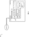
- FIG. 1 is a diagram of an example integrated protection system (IPS) 100, according to an implementation.
- the IPS 100 can provide a smart high integrity protection system for self-adjusting, self-diagnosis, and constantly monitoring the mechanical integrity of a piping system (for example, a pipeline or pipeline network).
- the IPS 100 can facilitate real-time adjustments to the trip set point of the protection layer used, for example, on a pipeline.
- the IPS 100 can be computer-implemented, including at least one computer interoperably coupled with a memory storage.
- the IPS 100 can be any feasible combination of components that are mechanical, electrical or computerized-implemented.
- the IPS 100 can be an integrated overpressure protection system, such as determining, managing and protecting against overpressure and related situations.
- the IPS can determine a trip set point adjustment and provide the trip set point adjustment as a threshold to actuate the final elements.
- the IPS 100 includes a computer-based corrosion/erosion module 112 communicatively coupled with a probe 110 that estimates corrosion/erosion rates in a pipeline based on metal loss measurements (for example, measures metal concentrations) due to a liquid (for example, oil or some other petroleum product) or a gas that passes through a pipeline 104 with erosive or corrosive elements.
- metal loss measurements for example, measures metal concentrations
- monitoring points for the corrosion/erosion module 112 can be at the wellhead or can be installed at a distance where the highest corrosion/erosion rates in the pipe network are expected. The monitoring points can communicate with the corrosion/erosion module 112 using any communication hardware, software, protocol, method, etc.
- the oil, gas, or other petroleum product can include (or be mixed with) amounts of natural components, such as produced water, sand, or soil, and can include (or be mixed with) man-made components, such as additives that facilitate the flow of material through a pipeline.
- a High Integrity Protection System (HIPS) 101 that is upstream of the computer-based corrosion/erosion module 112, includes at least two pressure-sensing elements 108 (connected to the pipeline 104) that capture pressure readings associated with inside pressures of the pipeline 104.
- the HIPS 101 also includes at least two final elements (for example, HIPS valves 106) configured to stop a flow of fluid through the pipeline 104.
- the HIPS 101 can be located at a wellhead or a location remote from the wellhead.
- the corrosion/erosion module 112 can receive metal concentration measurements 122 from the probe 110.
- the corrosion/erosion module 112 can use the received metal concentration measurements 122 to automatically determine and monitor, in real time, corrosion/erosion rates 122 in the pipeline 104.
- the at least one pressure-sensing element 108 connected to the pipeline 104, can capture pressure readings 116 associated with an inside pressure of the pipeline 104.
- multiple pressure-sensing elements 108 can be used, for example, three pressure-sensing elements 108 in a two-out-of-three voting configuration. Other quantities, configurations, and placements of the pressure-sensing elements 108 along the pipeline 104 are possible.
- At least one final element can be configured to stop flow of the liquid through the pipeline 104.
- multiple HIPS valves 106 can be used, for example, such as two HIPS valves 106 that are used, for example, in a one-out-of-two voting configuration.
- either valve is capable to stop the flow of fluid in the pipeline 104 when the pressure trip set point is reached and a logic solver, such as Logic Solver 102, sends a signal to close the HIPS valves 106.
- a logic solver such as Logic Solver 102
- Other quantities and arrangements of the HIPS valves 106 are possible.
- final elements can include valves, or other final elements consistent with this disclosure (for example, Electrical Submersible Pumps (ESPs)).
- ESPs Electrical Submersible Pumps
- Logic Solver 102 is coupled with the corrosion/erosion module 112 and the HIPS 101.
- Logic Solver 102 includes a built-in algorithm to process input from the corrosion/erosion module 112 and can execute logic (e.g., a calculation block) that modifies a high-pressure trip set point according to metal loss prediction.
- the logic solver is configured to automatically monitor mechanical integrity of the pipeline 104 in real time using the captured pressure readings and estimated metal loss measurements from the corrosion/erosion module 112. The logic solver can determine a trip set point adjustment using the estimated metal loss measurements and actuate the final elements when necessary under the new high pressure set point.
- the Logic Solver 102 can be configured to adjust a trip set point to trip the HIPS valves 106 based, at least in part, on various inputs that are received.
- inputs received by the Logic Solver 102 can include corrosion/erosion rates 120 and pressure readings 116 received from the pressure sensor elements 108.
- the Logic Solver 102 can be solid state or electronic (for example, an electronic programmable logic controller (e-PLC)).
- the signals received from the Logic Solver 102 by the HIPS valves 106 (or other final points) can include various commands.
- the IPS 100 can achieve a safe state when at least two values are met (for example, by the HIPS valves 106 closing), for example, when the logic solver is configured for two-out-of-three voting from sensing elements 108.
- varying types of final elements can be used, such as isolation valves, electrical switch gears to cut power to Electrical Submersible Pumps (ESPs), and Variable Frequency Drives (VFDs) to stop ESPs.
- ESPs Electrical Submersible Pumps
- VFDs Variable Frequency Drives
- Each of these example types of final elements can support the concept of modifying the HIPS trip set point based on mechanical integrity conditions being analyzed by the corrosion/erosion monitor module in one or multiple points within the piping network being protected by the HIPS.
- information associated with the conditions can constantly feed the Logic Solver 102 to modify, in real time, the HIPS trip set point regardless the type of the final element used for the system (for example, valves, pumps, compressors, and other components).
- commands and controls sent by the Logic Solver 102 to the HIPS valves 106 can include commands other than open/close, for example, to stop flow, such as by cutting a source of energy to cut power to electrical pumps, or closing valves to isolate the pressure.
- Other commands can be used, for example, as a result of monitoring the health of integrated protection system.
- other commands can be used to achieve an ultimate goal of protecting the downstream system from experiencing overpressure scenarios beyond the actual Maximum Allowable Operating Pressure (MAOP) of the piping network downstream.
- MAOP Maximum Allowable Operating Pressure
- the Logic Solver 102 can include custom hardware and software, for example, in an existing Logic Solver type hardware box.
- SIL Safety Integrity Level
- the Logic Solver 102 can include a custom-made solid state logic solvers to include/provide features described in this disclosure.
- an external Logic Solver can be added to the system.
- the external Logic Solver for example, can run algorithms and provide the solid-state logic solver with new trip set points.
- the external Logic Solver can trip the system due to a detected or suspected compromise of the mechanical integrity downstream.
- other HIPS applications can use Logic Solvers which can be modified, for example, by adding new logic to include the new capabilities described by his disclosure.
- software-only modifications to existing Logic Solvers may be sufficient, for example, if the available capacity of the Logic Solvers accept new inputs and outputs.
- the PLC can use special and proprietary algorithms in combination with basic threshold/comparisons and decision gates based on the comparisons.
- applications can be implemented in solid-state types of logic solvers, for example, using thresholds/comparisons and decision gates based on actual readings.
- the Logic Solver 102 can reside at a control facility of the oil company or some other location.
- HIPS applications can reside on offshore platforms, or in onshore environments (for example, wellheads in the middle of the desert) with standalone units.
- HIPS applications can communicate using supervisory control and data acquisition (SCADA) systems, for example, a control room for alarming or annunciation.
- SCADA supervisory control and data acquisition
- actions can be taken at a standalone unit independently of the communication link, for example, using hardwired connections for executive actions, to provide high integrity.
- the Logic Solver 102, HIPS 101, and corrosion/erosion modules 112 can use hard-wired communications.
- communications can include soft communication links, for example, using the Intranet and other network(s).
- the communication techniques that are chosen can depend, for example, on desired integrity levels, for example, for capturing the corrosion degradation at points far from the source of pressure. For example, depending on where the HIPS 101 is usually installed (for example, typically remotely), such configurations can potentially rely on soft links or any other communication protocol to feed the Logic Solver.
- monitoring that is done by the corrosion/erosion module 112 can include storing metal concentration measurements 122 that are received over time. For example, by analyzing stored metal concentration measurements 122, the corrosion/erosion module 112 can determine the corrosion/erosion rate 120 for the pipeline 104.
- stored metal concentration measurements 122 can include, in addition to quantitative and qualitative metal concentration information, a timestamp indicating when the measurement was taken, location information associated with the probe 110, and other information that is needed over time.
- the corrosion/erosion module 112 can receive signals and inputs from other reading points (for example, in addition to the probe 110) that collect corrosion/erosion data afar from the wellhead.
- monitoring that is done by the corrosion/erosion module 112 (or by other components of the IPS 100, such as the Logic Solver 102), can include storing, for example, a threshold metal concentration and a threshold corrosion/erosion rate associated with HIPS reporting requirements for the pipeline 104.
- Alarms can be provided, for example, if the corrosion/erosion rate 120 reaches the threshold corrosion/erosion rate or if the current metal concentration exceeds the threshold metal concentration.
- a trip set point can be automatically adjusted in the logic solver according to an analysis of the data, the preloaded thresholds, and trip set points. For example, the automatically adjusting can be based on degradation of a Maximum Allowable Working Pressure (MAWP) of the downstream piping network.
- MAWP Maximum Allowable Working Pressure
- the trip set point can be adjusted according real-time measurements of corrosion or erosion rates.
- An online corrosion/erosion monitoring system for example, provided by the corrosion/erosion module 112, can measure the corrosion/erosion rates and provide feedback to the Logic Solver 102.
- built-in logic of the Logic Solver 102 can correlate the material loss due to corrosion or erosion mechanisms with the actual MAWP of a piping system (for example, the pipeline 104). Losing material off of the wall of a piping system is generally directly correlated to the capacity of the equipment/piping to withstand pressures. Further, as more material is lost (for example, from the walls of the pipeline 104), less pressure can be withstand by the system.
- the IPS 100 can be used, for example, to monitor a pipeline over time, as conditions change, such as metal corrosion/erosion in a pipeline.
- corrosion/erosion monitoring systems can analyze the probe 110 readings within the internal module and provide the input to the Logic Solver 102 for adjusting the trip set point.
- electrical resistance probes can be used in conductive systems, as well as non-conductive environments such as oil, gas, and atmosphere. According to the present invention, such systems monitor and measure a change in resistance of the probe 110 as it is exposed to corrosive/erosive conditions. The information that is determined can be used as an electrical signal to the Logic Solver 102 that can use the information in a programmed logic/algorithm (such as, software or built-in solid state logic), to modify the trip set point.
- a programmed logic/algorithm such as, software or built-in solid state logic
- probes 110 can be spaced in different ways, such as scattered along a pipeline.
- one probe 110 can be positioned just downstream of the HIPS valves 106 as well as at multiple measuring points, depending on the length of the system and the weakest point(s) such as, those having a higher risk of corrosion/erosion (for example, produced water stagnation/accumulation is known to cause higher corrosion rates, hence low velocity sections of a pipeline or low points where water accumulation is possible may corrode the pipeline 104 faster).
- the HIPS' performance is improved by configuring the HIPS as a robust/strong layer of protection for the downstream system, even after years of operation exposed to a corrosive or erosive environment. Due to constant monitoring of equipment mechanical integrity, the HIPS will be capable of using input from the online corrosion/monitoring system to adjust the high-pressure trip set point accordingly.
- the logarithmic-based algorithm programmed as part of the PLC to support the corrosion/erosion online monitoring can support diagnosis features used with a Human-Machine interface for annunciation and time stamping of degradation of the conditions being monitored that are correlated to the integrity of the downstream system.
- the system can be programmed to detect considerable metal loss prior to reducing the trip set point in order to protect what could be the weakest link in the system.
- the disclosed subject matter is applicable not only to applications that require smart logic and a PLC, but also can be considered for stand-alone overpressure protection systems deployed in remote areas with hydraulic HIPS type systems.
- the hydraulic HIPS units deployed in remote areas are mandated to be tested with prescribed and mandatory frequencies to guarantee the integrity of the components and the availability of the HIPS.
- the test will prove the functionality of the HIPS, however typically the HIPS high-pressure trip set point is not modified to match the actual condition of the downstream system, and often there is a disconnection with the management of the mechanical integrity of the piping and the integrity of the HIPS systems.
- An integrated corrosion monitoring system is part of the disclosed HIPS design, permitting inspection on a regular basis to ascertain the actual condition of the piping system protected against overpressure. This information can be collected by the operators and be part of the lifecycle management of the safety function.
- the action adjusts the HIPS trip set point based on a prediction of degradation of downstream systems.
- Implementation of corrosion or erosion probe/s or a metal loss detection system is used to predict the potential metal loss of downstream piping with dedicated instruments to provide a verification element that will maintain a correlation with the HIPS trip set point and the current state of the piping system.
- the corrosion or erosion probe will be integrated with the HIPS skid equipment so it can be tracked, removed and inspected at a prescribed frequency as part of the testing and verification of the associated HIPS system.
- the disclosed subject matter provides information on a one-to-one basis regarding pipe conditions over time, which can be extrapolated to the metal loss that the system maybe experiencing downstream.
- Mechanical integrity of a piping network is an important design feature that could degrade due to corrosion/erosion mechanisms if not maintained. The corrosion/erosion may not be noticed in time to prevent degradation, rendering the HIPS as an ineffective layer of protection.
- HIPS trip setting As a fixed value that is not adjusted over time according to the metal loss that maybe experienced in the system.
- the disclosed subject matter provides real time critical information using proven technology that allows the correction of the HIPS trip set points protecting the weakest link in the system, in this case a corroded/eroded or degraded section of a vessel or piping network.
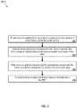
- FIG. 2 illustrates a method 200 for protecting a pipeline within an integrated protection system.
- Method 200 may be performed by any system, environment, software, and hardware, or a combination of systems, environments, software, and hardware as appropriate (for example, the computer system described in FIG. 3 below).
- various steps of method 200 can be ran in parallel, in combination, in loops, or in any order.
- pressure readings are received from at least one pressure-sensing element of a High Integrity Protection System (HIPS).
- HIPS High Integrity Protection System
- the Logic Solver 102 can receive pressure readings 116 from the pressure sensing elements 108. From 202, method 200 proceeds to 204.
- metal concentration measurements and corrosion/erosion rates are received from a computer-implemented corrosion/erosion module downstream of the HIPS.
- the Logic Solver 102 can receive the corrosion/erosion rates 120 and metal concentration measurements 122 from the corrosion/erosion module 112.
- the information can be received over time, for example, at regular or scheduled intervals.
- the information can be received whenever demanded by the Logic Solver 102.
- the information can be sent by the corrosion/erosion module 112, as needed, for example, when a spike in corrosion/erosion rates 120 is detected or when metal concentration measurements 122 reach a threshold level. From 204, method 200 proceeds to 206.
- a trip set point adjustment is determined using the metal concentration measurements, and the corrosion/erosion rates.
- the Logic Solver 102 can determine a trip set point adjustment using industry standard or innovative algorithms and specific guidelines associated with the pipeline 104. From 206, method 200 proceeds to 208.
- trip set point adjustments can be based, at least in part, on other factors, for example, current seismic or other geopolitical conditions, weather conditions, intelligence related to threats to the pipeline's operation, regulatory inputs, and inputs received from the pipeline's owners.
- the trip set point adjustment is provided to the at least one final element of the HIPS.
- the Logic Solver 102 can provide trip set point adjustments for actuating the final elements valves 106 when the pressure new trip set point is sensed by the sensing elements 108. From 208, method 200 terminates.
- FIG. 3 is a block diagram illustrating an Exemplary Distributed Computer System (EDCS) 300 used for providing integrated protection of a pipeline, according to an implementation.
- the EDCS 300 includes a computer 302 and network 330.
- the illustrated computer 302 includes a Logic Solver 307 (for example, the Logic Solver 102 or at least one other logic solver) that is coupled with a computer-based corrosion/erosion module and an HIPS.
- the Logic Solver 307 is configured to automatically monitor mechanical integrity of a pipeline in real time using captured pressure readings and estimated metal loss measurements from the computer-based corrosion/erosion module. Based on the received information, the Logic Solver 307 can determine (and provide to the HIPS) a trip set point adjustment using the estimated metal loss measurements and provide the trip set point adjustment to final elements of the HIPS.
- the illustrated computer 302 is intended to encompass a computing device such as a server, desktop computer, laptop/notebook computer, wireless data port, smart phone, personal data assistant (PDA), tablet computing device, one or more processors within these devices, or any other processing device, including either or both of both physical and virtual instances of the computing device.
- the computer 302 may comprise a computer that includes an input device, such as a keypad, keyboard, touch screen, or other device (not illustrated) that can accept user information, and an output device (not illustrated) that conveys information associated with the operation of the computer 302, including digital data, visual and audio information, or a user interface.
- the computer 302 can serve as a client or a server. In typical implementations, the computer 302 act as either a parallel processing node, a host for a software agent, or other application consistent with this disclosure (even if not illustrated).
- the illustrated computer 302 is communicably coupled with a network 330 for example that allows the computer 302 to communicate, for example, with the computer-based corrosion/erosion module 112 and the HIPS 101.
- one or more components of the computer 302 may be configured to operate within a parallel-processing or cloud-computing-based environment. Implementations of the computer 302 can also communicate using message passing interface (MPI) or other interface over network 330.
- MPI message passing interface
- the computer 302 is an electronic computing device operable to receive, transmit, process, store, or manage data and information associated with modeling of reservoir formations and lithofacies distribution.
- the computer 302 may also include or be communicably coupled with a simulation server, application server, e-mail server, web server, caching server, streaming data server, business intelligence (BI) server, or other server.
- a simulation server application server, e-mail server, web server, caching server, streaming data server, business intelligence (BI) server, or other server.
- BI business intelligence
- Each of the components of the computer 302 can communicate using a system bus 303.
- any or all the components of the computer 302, both hardware or software may interface with each other and the interface 304 over the system bus 303 using an application programming interface (API) 312 or a service layer 313.
- the API 312 may include specifications for routines, data structures, and object classes.
- the API 312 may be either computer-language independent or dependent and refer to a complete interface, a single function, or even a set of APIs.
- the service layer 313 provides software services to the computer 302 or system of which the computer 302 is a part. The functionality of the computer 302 may be accessible for all service consumers using this service layer.
- Software services such as those provided by the service layer 313, provide reusable, defined business functionalities through a defined interface.
- the interface may be software written in JAVA, C++, or other language providing data in extensible markup language (XML) format or other format.
- XML extensible markup language
- alternative implementations may illustrate the API 312 or the service layer 313 as stand-alone components in relation to other components of the computer 302.
- any or all parts of the API 312 or the service layer 313 may be implemented as child or sub-modules of another software module, enterprise application, or hardware module without departing from the scope of this disclosure.
- the computer 302 includes an interface 304. Although illustrated as a single interface 304 in FIG. 3 , two or more interfaces 304 may be used according to particular needs, desires, or particular implementations of the computer 302.
- the interface 304 is used by the computer 302 for communicating with other systems in a distributed environment - including a parallel processing environment- connected to the network 330 (whether illustrated or not).
- the interface 304 can facilitate communications with the computer-based corrosion/erosion module 112 and the HIPS 101.
- the interface 304 comprises logic encoded in software or hardware operable to communicate with the network 330. More specifically, the interface 304 may comprise software supporting one or more communication protocols associated with communications over network 330.
- the computer 302 includes a processor 305. Although illustrated as a single processor 305 in FIG. 3 , two or more processors may be used according to particular needs, desires, or particular implementations of the computer 302. Generally, the processor 305 executes instructions and manipulates data to perform the operations of the computer 302.
- the computer 302 also includes a memory 306 that holds data for the computer 302 or other components of a system of which the computer is a part. Although illustrated as a single memory 306 in FIG. 3 , two or more memories may be used according to particular needs, desires, or particular implementations of the computer 302. While memory 306 is illustrated as an integral component of the computer 302, in alternative implementations, memory 306 can be external to the computer 302. In some implementations, for example, memory 306 can hold algorithms 314 used for protecting a pipeline system.
- computers 302 there may be any number of computers 302 associated with a computer system performing functions consistent with this disclosure. Further, the term “client,” “user,” and other appropriate terminology may be used interchangeably as appropriate without departing from the scope of this disclosure. Moreover, this disclosure contemplates that many users/processes may use one computer 302, or that one user/process may use multiple computers 302.
- Implementations of the subject matter and the functional operations described in this specification can be implemented in digital electronic circuitry, in tangibly-embodied computer software or firmware, in computer hardware, including the structures disclosed in this specification and their structural equivalents, or in combinations of one or more of them.
- Implementations of the subject matter described in this specification can be implemented as one or more computer programs, i.e., one or more modules of computer program instructions encoded on a tangible, non-transitory computer-storage medium for execution by, or to control the operation of, data processing apparatus.
- the program instructions can be encoded on an artificially-generated propagated signal, for example, a machine-generated electrical, optical, or electromagnetic signal that is generated to encode information for transmission to receiver apparatus for execution by a data processing apparatus.
- the computer-storage medium can be a machine-readable storage device, a machine-readable storage substrate, a random or serial access memory device, or a combination of one or more of them.
- data processing apparatus refers to data processing hardware and encompasses all kinds of apparatus, devices, and machines for processing data, including by way of example, a programmable processor, a computer, or multiple processors or computers.
- the apparatus can also be or further include special purpose logic circuitry, for example, a central processing unit (CPU), a co-processor (for example, a graphics/visual processing unit (GPU/VPU)), a FPGA (field programmable gate array), or an ASIC (application-specific integrated circuit).
- the data processing apparatus or special purpose logic circuitry may be hardware-based or software-based.
- the apparatus can optionally include code that creates an execution environment for computer programs, for example, code that constitutes processor firmware, a protocol stack, a database management system, an operating system, or a combination of one or more of them.
- code that constitutes processor firmware for example, code that constitutes processor firmware, a protocol stack, a database management system, an operating system, or a combination of one or more of them.
- the present disclosure contemplates the use of data processing apparatuses with or without conventional operating systems, for example LINUX, UNIX, WINDOWS, MAC OS, ANDROID, IOS or any other conventional operating system.
- a computer program which may also be referred to or described as a program, software, a software application, a module, a software module, a script, or code, can be written in any form of programming language, including compiled or interpreted languages, or declarative or procedural languages, and it can be deployed in any form, including as a stand-alone program or as a module, component, subroutine, or other unit for use in a computing environment.
- a computer program may, but need not, correspond to a file in a file system.
- a program can be stored in a portion of a file that holds other programs or data, for example, one or more scripts stored in a markup language document, in a single file dedicated to the program in question, or in multiple coordinated files, for example, files that store one or more modules, sub-programs, or portions of code.
- a computer program can be deployed to be executed on one computer or on multiple computers that are located at one site or distributed across multiple sites and interconnected by a communication network. While portions of the programs illustrated in the various figures are shown as individual modules that implement the various features and functionality through various objects, methods, or other processes, the programs may instead include a number of sub-modules, third-party services, components, libraries, and such, as appropriate. Conversely, the features and functionality of various components can be combined into single components as appropriate.
- the processes and logic flows described in this specification can be performed by one or more programmable computers executing one or more computer programs to perform functions by operating on input data and generating output.
- the processes and logic flows can also be performed by, and apparatus can also be implemented as, special purpose logic circuitry, for example, a CPU, a FPGA, or an ASIC.
- Computers for executing a computer program can be based on general or special purpose microprocessors, both, or any other kind of CPU.
- a CPU will receive instructions and data from a read-only memory (ROM) or a random access memory (RAM) or both.
- the essential elements of a computer are a CPU for performing or executing instructions and one or more memory devices for storing instructions and data.
- a computer will also include, or be operatively coupled to, receive data from or transfer data to, or both, one or more mass storage devices for storing data, for example, magnetic, magneto-optical disks, or optical disks.
- mass storage devices for storing data, for example, magnetic, magneto-optical disks, or optical disks.
- a computer need not have such devices.
- a computer can be embedded in another device, for example, a mobile telephone, a personal digital assistant (PDA), a mobile audio or video player, a game console, a global positioning system (GPS) receiver, or a portable storage device, for example, a universal serial bus (USB) flash drive, to name just a few.
- PDA personal digital assistant
- GPS global positioning system
- USB universal serial bus
- Computer-readable media for storing computer program instructions and data include all forms of non-volatile memory, media and memory devices, including by way of example semiconductor memory devices, for example, erasable programmable read-only memory (EPROM), electrically-erasable programmable read-only memory (EEPROM), and flash memory devices; magnetic disks, for example, internal hard disks or removable disks; magneto-optical disks; and CD-ROM, DVD+/-R, DVD-RAM, and DVD-ROM disks.
- semiconductor memory devices for example, erasable programmable read-only memory (EPROM), electrically-erasable programmable read-only memory (EEPROM), and flash memory devices
- EPROM erasable programmable read-only memory
- EEPROM electrically-erasable programmable read-only memory
- flash memory devices for example, internal hard disks or removable disks
- magneto-optical disks for example, internal hard disks or removable disks
- the memory may store various objects or data, including caches, classes, frameworks, applications, backup data, jobs, web pages, web page templates, database tables, repositories storing business or dynamic information, and any other appropriate information including any parameters, variables, algorithms, instructions, rules, constraints, or references thereto. Additionally, the memory may include any other appropriate data, such as logs, policies, security or access data, reporting files, as well as others.
- the processor and the memory can be supplemented by, or incorporated in, special purpose logic circuitry.
- implementations of the subject matter described in this specification can be implemented on a computer having a display device, for example, a CRT (cathode ray tube), LCD (liquid crystal display), LED (Light Emitting Diode), or plasma monitor, for displaying information to the user and a keyboard and a pointing device, for example, a mouse, trackball, or trackpad by which the user can provide input to the computer.
- a display device for example, a CRT (cathode ray tube), LCD (liquid crystal display), LED (Light Emitting Diode), or plasma monitor
- a keyboard and a pointing device for example, a mouse, trackball, or trackpad by which the user can provide input to the computer.
- Input may also be provided to the computer using a touchscreen, such as a tablet computer surface with pressure sensitivity, a multi-touch screen using capacitive or electric sensing, or other type of touchscreen.
- a computer can interact with a user by sending documents to and receiving documents from a device that is used by the user; for example, by sending web pages to a web browser on a user's client device in response to requests received from the web browser.
- GUI graphical user interface
- GUI may be used in the singular or the plural to describe one or more graphical user interfaces and each of the displays of a particular graphical user interface. Therefore, a GUI may represent any graphical user interface, including but not limited to, a web browser, a touch screen, or a command line interface (CLI) that processes information and efficiently presents the information results to the user.
- a GUI may include a plurality of UI elements, some or all associated with a web browser, such as interactive fields, pull-down lists, and buttons operable by the business suite user. These and other UI elements may be related to or represent the functions of the web browser.
- Implementations of the subject matter described in this specification can be implemented in a computing system that includes a back-end component, for example, as a data server, or that includes a middleware component, for example, an application server, or that includes a front-end component, for example, a client computer having a graphical user interface or a Web browser through which a user can interact with an implementation of the subject matter described in this specification, or any combination of one or more such back-end, middleware, or front-end components.
- the components of the system can be interconnected by any form or medium of wireline or wireless digital data communication, for example, a communication network.
- Examples of communication networks include a local area network (LAN), a radio access network (RAN), a metropolitan area network (MAN), a wide area network (WAN), Worldwide Interoperability for Microwave Access (WIMAX), a wireless local area network (WLAN) using, for example, 802.11 a/b/g/n or 802.20, all or a portion of the Internet, or any other communication system or systems at one or more locations.
- the network may communicate with, for example, Internet Protocol (IP) packets, Frame Relay frames, Asynchronous Transfer Mode (ATM) cells, voice, video, data, or other information between network addresses.
- IP Internet Protocol
- ATM Asynchronous Transfer Mode
- the computing system can include clients and servers.
- a client and server are generally remote from each other and typically interact through a communication network.
- the relationship of client and server arises by virtue of computer programs running on the respective computers and having a client-server relationship to each other.
- any or all of the components of the computing system may interface with each other or the interface using an application programming interface (API) or a service layer.
- the API may include specifications for routines, data structures, and object classes.
- the API may be either computer language independent or dependent and refer to a complete interface, a single function, or even a set of APIs.
- the service layer provides software services to the computing system. The functionality of the various components of the computing system may be accessible for all service consumers using this service layer.
- Software services provide reusable, defined business functionalities through a defined interface.
- the interface may be software written in JAVA, C++, or other language providing data in extensible markup language (XML) or other format.
- the API and service layer may be an integral or a stand-alone component in relation to other components of the computing system. Moreover, any or all parts of the service layer may be implemented as child or sub-modules of another software module, enterprise application, or hardware module without departing from the scope of this disclosure.
Landscapes
- Life Sciences & Earth Sciences (AREA)
- Physics & Mathematics (AREA)
- Environmental & Geological Engineering (AREA)
- Engineering & Computer Science (AREA)
- Geology (AREA)
- Mining & Mineral Resources (AREA)
- Immunology (AREA)
- Biodiversity & Conservation Biology (AREA)
- Analytical Chemistry (AREA)
- Biochemistry (AREA)
- General Health & Medical Sciences (AREA)
- General Physics & Mathematics (AREA)
- Environmental Sciences (AREA)
- Pathology (AREA)
- Ecology (AREA)
- Chemical & Material Sciences (AREA)
- Health & Medical Sciences (AREA)
- Fluid Mechanics (AREA)
- General Life Sciences & Earth Sciences (AREA)
- Geochemistry & Mineralogy (AREA)
- Geophysics (AREA)
- Pipeline Systems (AREA)
- Testing Resistance To Weather, Investigating Materials By Mechanical Methods (AREA)
Claims (10)
- Integriertes Schutzsystem, umfassend:ein computerbasiertes Korrosions-/Erosionsmodul (112), das mit einer Sonde (110) kommunikativ gekoppelt ist, um Korrosions-/Erosionsraten in einer Rohrleitung (104) basierend auf Metallverlustmessungen zu schätzen, wobei die Sonde (110) eine elektrische Widerstandssonde ist, die so ausgelegt ist, dass sie den Widerstand ändert, wenn sie Korrosions-/Erosionsbedingungen in einer Flüssigkeit oder einem Gas ausgesetzt wird, die/das durch die Pipeline durchströmt,ein Schutzsystem mit hoher Integrität (101) stromaufwärts der Sonde, das mit dem computerbasierten Korrosions-/Erosionsmodul kommunikativ gekoppelt ist, wobei das Schutzsystem mit hoher Integrität umfasst:mindestens zwei Drucksensorelemente (108), die mit der Rohrleitung verbunden sind und Druckmesswerte erfassen, die mit Innendrücken der Rohrleitung assoziiert sind, undmindestens zwei Schlusselemente (106), die zum Stoppen eines Stroms von Fluid durch die Rohrleitung ausgelegt sind; undein Logiksystem (102), das mit dem computerbasierten Korrosions-/Erosionsmodul und dem HIPS gekoppelt ist, wobei das Logiksystem ausgelegt ist zum automatischen Überwachen der mechanischen Integrität der Rohrleitung in Echtzeit unter Verwendung der erfassten Druckmesswerte und der geschätzten Metallverlustmessungen vom computerbasierten Korrosions-/Erosionsmodul und zumBestimmen einer Abschaltpunkteinstellung unter Verwendung der geschätzten Metallverlustmessungen, undBereitstellen der Abschaltpunkteinstellung für die Schlusselemente.
- Integriertes Schutzsystem nach Anspruch 1, wobei das Fluid in der geschützten Rohrleitung ein Erdölprodukt ist, das Öl oder Gas umfasst.
- Integriertes Schutzsystem nach Anspruch 1, wobei das computerimplementierte integrierte Schutzsystem einen sicheren Zustand erreicht, wenn mindestens zwei für Zwei-aus-drei-Wahl im Logiksystem konfigurierte Druckwerte erfüllt werden oder wenn ein gemessener Druck für mindestens eines von zwei Drucksensorelementen in einer Ein-aus-zwei-Wahl-Konfiguration sicher ist.
- Integriertes Schutzsystem nach Anspruch 1, wobei das Schutzsystem mit hoher Integrität sich in einem Bohrlochkopf oder an einer vom Bohrlochkopf entfernten Stelle befindet.
- Integriertes Schutzsystem nach Anspruch 1, wobei die Schlusselemente Ventile des Schutzsystems mit hoher Integrität, elektrische Tauchpumpen oder Schalteinrichtungen umfassen.
- Integriertes Schutzsystem nach Anspruch 1, wobei das integrierte Schutzsystem mechanisch, elektrisch oder computerimplementiert ist.
- Computerimplementiertes Verfahren (200), das unter Verwendung des integrierten Schutzsystems nach Anspruch 1 durchgeführt wird, wobei die Sonde eine elektrische Widerstandssonde ist, die so ausgelegt ist, dass sie den Widerstand ändert, wenn sie Korrosions-/Erosionsbedingungen in einer Flüssigkeit oder einem Gas ausgesetzt wird, die/das durch die Pipeline durchströmt, wobei das Verfahren umfasst:Empfangen (202) von Druckmesswerten von mindestens einem der Drucksensorelemente (108) des Schutzsystems mit hoher Integrität;Empfangen (204) von Korrosions-/Erosionsraten in der Rohrleitung (104) basierend auf Metallverlustmessungen vom computerbasierten Korrosions-/Erosionsmodul, wobei das computerbasierte Korrosions-/Erosionsmodul stromabwärts des Schutzsystems mit hoher Integrität liegt;Bestimmen (206) einer Abschaltpunkteinstellung unter Verwendung der Korrosions-/Erosionsraten; undBereitstellen (208) der Abschaltpunkteinstellung für mindestens ein Ventil des Schutzsystems mit hoher Integrität.
- Computerimplementiertes Verfahren nach Anspruch 7, ferner umfassend:
automatisches Überwachen der mechanischen Integrität der Rohrleitung (104) in Echtzeit durch das Logiksystem (307) unter Verwendung von Druckmesswerten und der vom computerbasierten Korrosions-/Erosionsmodul empfangenen Korrosions-/Erosionsraten, wobei das automatische Überwachen umfasst:Speichern der empfangenen Metallverlustmessschätzungen im Zeitablauf; undBestimmen der Korrosions-/Erosionsrate für die Rohrleitung unter Verwendung der empfangenen und gespeicherten Metallverlustmessschätzungen. - Computerimplementiertes Verfahren nach Anspruch 7, wobei das Fluid in der geschützten Rohrleitung ein Erdölprodukt ist, das Öl oder Gas umfasst.
- Computerimplementiertes Verfahren nach Anspruch 7, wobei das computerimplementierte integrierte Schutzsystem einen sicheren Zustand erreicht, wenn mindestens zwei für Zwei-aus-drei-Wahl im Logiksystem konfigurierte Druckwerte erfüllt werden oder wenn ein gemessener Druck für mindestens eines von zwei Drucksensorelementen in einer Ein-aus-zwei-Wahl-Konfiguration sicher ist.
Applications Claiming Priority (2)
| Application Number | Priority Date | Filing Date | Title |
|---|---|---|---|
| US15/150,862 US10753852B2 (en) | 2016-05-10 | 2016-05-10 | Smart high integrity protection system |
| PCT/US2017/018048 WO2017196420A1 (en) | 2016-05-10 | 2017-02-16 | Smart high integrity protection system |
Publications (2)
| Publication Number | Publication Date |
|---|---|
| EP3455609A1 EP3455609A1 (de) | 2019-03-20 |
| EP3455609B1 true EP3455609B1 (de) | 2022-04-06 |
Family
ID=58192378
Family Applications (1)
| Application Number | Title | Priority Date | Filing Date |
|---|---|---|---|
| EP17708369.8A Active EP3455609B1 (de) | 2016-05-10 | 2017-02-16 | Intelligentes high-integrity-protection-system und zugehöriges verfahren |
Country Status (4)
| Country | Link |
|---|---|
| US (1) | US10753852B2 (de) |
| EP (1) | EP3455609B1 (de) |
| JP (1) | JP6973754B2 (de) |
| WO (1) | WO2017196420A1 (de) |
Families Citing this family (16)
| Publication number | Priority date | Publication date | Assignee | Title |
|---|---|---|---|---|
| US10753852B2 (en) | 2016-05-10 | 2020-08-25 | Saudi Arabian Oil Company | Smart high integrity protection system |
| US11261726B2 (en) | 2017-02-24 | 2022-03-01 | Saudi Arabian Oil Company | Safety integrity level (SIL) 3 high-integrity protection system (HIPS) fully-functional test configuration for hydrocarbon (gas) production systems |
| US10570712B2 (en) * | 2017-04-17 | 2020-02-25 | Saudi Arabian Oil Company | Protecting a hydrocarbon fluid piping system |
| US10663988B2 (en) | 2018-03-26 | 2020-05-26 | Saudi Arabian Oil Company | High integrity protection system for hydrocarbon flow lines |
| CN109138982B (zh) * | 2018-11-16 | 2023-09-26 | 美钻深海能源科技研发(上海)有限公司 | 水下装备生物腐蚀自动安全关井系统 |
| CN109403904B (zh) * | 2018-12-13 | 2023-12-15 | 美钻深海能源科技研发(上海)有限公司 | 水下装备电位腐蚀自动安全关井系统 |
| KR102239706B1 (ko) * | 2019-04-03 | 2021-04-13 | 한국조선해양 주식회사 | 액화가스 재기화 시스템 및 이를 구비하는 선박 |
| CN109765172A (zh) * | 2019-04-04 | 2019-05-17 | 中国船舶重工集团公司第七二五研究所 | 一种金属及涂层材料海洋大气腐蚀原位测量装置及方法 |
| US11143322B2 (en) * | 2019-05-06 | 2021-10-12 | Celeros Flow Technology, Llc | Systems and methods for providing surge relief |
| US11078755B2 (en) * | 2019-06-11 | 2021-08-03 | Saudi Arabian Oil Company | HIPS proof testing in offshore or onshore applications |
| US11377947B2 (en) * | 2019-10-16 | 2022-07-05 | Saudi Arabian Oil Company | Safety variable frequency drive for preventing over pressurization of a piping network |
| CN111151019B (zh) * | 2020-01-09 | 2021-07-20 | 四川点石能源股份有限公司 | 一种mvr技术用蒸发器循环管防堵塞系统 |
| CN111578150B (zh) * | 2020-05-27 | 2021-08-20 | 梁绘 | 一种油气输送管网安全在线实时监测与预警管理系统 |
| US20240044808A1 (en) * | 2022-08-03 | 2024-02-08 | Saudi Arabian Oil Company | System and method for detecting defects in pipelines |
| US20250257815A1 (en) * | 2024-02-08 | 2025-08-14 | Sri Energy, Inc. | Pressure relief valve with redundant pressure sensing |
| KR20250159976A (ko) * | 2024-05-03 | 2025-11-11 | 국립부경대학교 산학협력단 | 식수 공급 파이프의 부식 정도와 수질을 동시에 측정하는 다중 진단 시스템 및 방법 |
Family Cites Families (44)
| Publication number | Priority date | Publication date | Assignee | Title |
|---|---|---|---|---|
| US4215746A (en) | 1979-06-28 | 1980-08-05 | W-K-M Wellhead Systems, Inc. | Pressure responsive safety system for fluid lines |
| US5446369A (en) | 1992-10-09 | 1995-08-29 | Battelle Memorial Institute | Continuous, automatic and remote monitoring of corrosion |
| US5887657A (en) | 1995-02-09 | 1999-03-30 | Baker Hughes Incorporated | Pressure test method for permanent downhole wells and apparatus therefore |
| US6556027B2 (en) | 2001-01-12 | 2003-04-29 | Ondeo Nalco Company | Low cost, on-line corrosion monitor and smart corrosion probe |
| US6880567B2 (en) | 2001-11-01 | 2005-04-19 | Shell Oil Company | Over-pressure protection system |
| GB0213635D0 (en) | 2002-06-13 | 2002-07-24 | Alpha Thames Ltd | Pressure protection system |
| GB2401164B (en) | 2003-04-29 | 2006-01-18 | Abb Offshore Systems Ltd | Pipeline protection system |
| US7133727B2 (en) | 2003-08-01 | 2006-11-07 | Invensys Systems, Inc. | System and method for continuous online safety and reliability monitoring |
| US7034553B2 (en) * | 2003-12-05 | 2006-04-25 | Prodont, Inc. | Direct resistance measurement corrosion probe |
| JP2005308841A (ja) * | 2004-04-19 | 2005-11-04 | Hitachi Ltd | パイプライン管理データ処理装置、パイプライン管理データ処理方法、パイプライン管理データプログラム、及びパイプライン管理データ処理システム |
| JP4889734B2 (ja) * | 2006-05-12 | 2012-03-07 | 株式会社日立製作所 | 監視制御システム |
| GB2439552B (en) | 2006-05-20 | 2011-03-02 | Vetco Gray Controls Ltd | Pipeline protection system |
| WO2008008567A2 (en) * | 2006-07-12 | 2008-01-17 | Pepperl & Fuchs, Inc. | Corrosion measurement field device |
| US7905251B2 (en) | 2006-12-29 | 2011-03-15 | Saudi Arabian Oil Company | Method for wellhead high integrity protection system |
| US20110133942A1 (en) | 2006-12-29 | 2011-06-09 | Flanders Patrick S | Apparatus and method for clustered wellhead high integrity protection system |
| US8725434B2 (en) | 2006-12-29 | 2014-05-13 | Saudi Arabian Oil Company | Wellhead hips with automatic testing and self-diagnostics |
| GB0711843D0 (en) | 2007-06-19 | 2007-07-25 | Energy Equipment Corp | Method |
| US7823640B2 (en) | 2007-10-23 | 2010-11-02 | Saudi Arabian Oil Company | Wellhead flowline protection and testing system with ESP speed controller and emergency isolation valve |
| US8201624B2 (en) | 2007-10-23 | 2012-06-19 | Saudi Arabian Oil Company | Clustered wellhead trunkline protection and testing system with ESP speed controller and emergency isolation valve |
| WO2009146206A2 (en) | 2008-04-18 | 2009-12-03 | Schlumberger Canada Limited | Subsea tree safety control system |
| WO2009154874A1 (en) | 2008-06-16 | 2009-12-23 | Cameron International Corporation | Dual-acting multi-actuation mode gate valve |
| US8161993B2 (en) | 2008-09-23 | 2012-04-24 | Chevron U.S.A. Inc. | Subsea system and method for protecting equipment of a subsea system |
| US8776609B2 (en) | 2009-08-05 | 2014-07-15 | Shell Oil Company | Use of fiber optics to monitor cement quality |
| JP5297951B2 (ja) * | 2009-09-04 | 2013-09-25 | 株式会社日立製作所 | 防食データ解析システム |
| BR112013002186A2 (pt) | 2010-10-21 | 2016-05-31 | Saudi Arabian Oil Co | sistema automatizado para teste de segurança de um sistema de proteção instrumentado de linha-tronco e método para teste de segurança e falha de um sistema de proteção instrumentado de linha-tronco |
| BR112013018250A2 (pt) * | 2011-01-19 | 2016-11-08 | Saudi Arabian Oil Co | método para testar um sistema de proteção de alta integridade, sistema para prover diagnóstico de um sistema de proteção de alta integridade, sistema de proteção de alta integridade e método para operar um sistema de proteção de alta integridade |
| EP2592318B1 (de) | 2011-11-08 | 2014-10-22 | Vetco Gray Controls Limited | Pipelineschutzsysteme |
| WO2013126592A2 (en) | 2012-02-21 | 2013-08-29 | Cameron International Corporation | Well tree hub and interface for retrievable processing modules |
| AU2013263327B2 (en) | 2012-05-14 | 2015-08-20 | Landmark Graphics Corporation | Method and system of selecting hydrocarbon wells for well testing |
| EP2880602A4 (de) | 2012-08-01 | 2016-04-27 | Saudi Arabian Oil Co | System zur inspektion und wartung eines werks oder einer anderen anlage |
| EP2917127B1 (de) | 2013-01-25 | 2018-04-11 | Landmark Graphics Corporation | Bohrlochintegritätsverwaltung mithilfe einer gekoppelten technischen analyse |
| US9310288B2 (en) * | 2013-01-28 | 2016-04-12 | Fisher-Rosemount Systems, Inc. | Systems and methods to monitor operating processes |
| US20140261778A1 (en) | 2013-03-14 | 2014-09-18 | Pentair Valves & Controls UK Limited | High Integrity Pressure Protection System (HIPPS) Manifold System and Method |
| US9453386B2 (en) | 2013-12-31 | 2016-09-27 | Cameron International Corporation | Magnetorheological fluid locking system |
| PT3054203T (pt) | 2015-02-06 | 2017-08-28 | Mokveld Valves Bv | Colector de derivação de tubagem e método de operação do mesmo |
| GB2547675A (en) | 2016-02-25 | 2017-08-30 | Ge Oil & Gas Uk Ltd | Subsea high integrity pipeline protection system with bypass |
| US10753852B2 (en) | 2016-05-10 | 2020-08-25 | Saudi Arabian Oil Company | Smart high integrity protection system |
| US10248141B2 (en) | 2016-05-13 | 2019-04-02 | Cameron International Corporation | Non-invasive pressure measurement system |
| AU2017283494A1 (en) | 2016-06-13 | 2019-01-31 | Megamatter, Inc. | Modified graphite intercalated compounds and methods of making and using them |
| US10221645B2 (en) | 2016-06-15 | 2019-03-05 | Cameron International Corporation | High-integrity pressure protection system Christmas tree |
| NO342625B1 (en) | 2016-08-24 | 2018-06-25 | Fmc Kongsberg Subsea As | High-integrity pressure protection system and associated method |
| US20180156004A1 (en) | 2016-12-02 | 2018-06-07 | Onesubsea Ip Uk Limited | Integrated well system asset and high integrity pressure protection |
| US11261726B2 (en) | 2017-02-24 | 2022-03-01 | Saudi Arabian Oil Company | Safety integrity level (SIL) 3 high-integrity protection system (HIPS) fully-functional test configuration for hydrocarbon (gas) production systems |
| US10570712B2 (en) | 2017-04-17 | 2020-02-25 | Saudi Arabian Oil Company | Protecting a hydrocarbon fluid piping system |
-
2016
- 2016-05-10 US US15/150,862 patent/US10753852B2/en active Active
-
2017
- 2017-02-16 WO PCT/US2017/018048 patent/WO2017196420A1/en not_active Ceased
- 2017-02-16 JP JP2018559703A patent/JP6973754B2/ja active Active
- 2017-02-16 EP EP17708369.8A patent/EP3455609B1/de active Active
Also Published As
| Publication number | Publication date |
|---|---|
| US10753852B2 (en) | 2020-08-25 |
| EP3455609A1 (de) | 2019-03-20 |
| JP2019525076A (ja) | 2019-09-05 |
| WO2017196420A1 (en) | 2017-11-16 |
| JP6973754B2 (ja) | 2021-12-01 |
| US20170328827A1 (en) | 2017-11-16 |
Similar Documents
| Publication | Publication Date | Title |
|---|---|---|
| US10753852B2 (en) | Smart high integrity protection system | |
| US12359557B2 (en) | Safety integrity level (SIL) 3 high-integrity protection system (HIPS) fully-functional test configuration for hydrocarbon (gas) production systems | |
| AU2020325058B2 (en) | Method and system to monitor pipeline condition | |
| KR102332861B1 (ko) | 해저 제어 서브시스템 컴포넌트들에 대한 컴포넌트 건강상태 및 예방정비 요구들을 시각화하는 시스템들 및 방법들 | |
| US20170076209A1 (en) | Managing Performance of Systems at Industrial Sites | |
| US10590752B2 (en) | Automated preventive and predictive maintenance of downhole valves | |
| US10107932B2 (en) | Statistical methods for assessing downhole casing integrity and predicting casing leaks | |
| US20240402659A1 (en) | Real-Time Adaptive Control of Demulsifier Injection Using Self-Learning Artificial Intelligence Models | |
| EP4153952B1 (de) | Automatisierter algorithmus und echtzeit-system zur präventiven erkennung von wartungsbedarf von mehrphasen-durchflussmessgeräten | |
| EP4162329B1 (de) | Ein computer-implementiertes verfahren für ein prädiktives druckschutzsystem, nicht-transitorisches computer-lesbares medium und prädiktives druckschutzsystem | |
| EP3983642B1 (de) | Hips-abnahmeprüfung in offshore- oder onshore-anwendungen | |
| US20210400361A1 (en) | Fire water network leak detection system | |
| US12480401B2 (en) | Managing pipeline corrosion in oil and gas production | |
| US20250369819A1 (en) | Leak detection in transformers | |
| US20250369822A1 (en) | Water leak detection and repair | |
| US20250084841A1 (en) | Action-oriented monitoring system for rotating equipment | |
| Chen et al. | Adaptive Drilling Decision Support Using a Hybrid Physics-Data Approach: From Theory to Field Application | |
| Chze et al. | Optimising Data Processing for Subsea System Surveillance Through Subsea Condition Monitoring | |
| NEL | Paper 3.1 A Review of Pipeline Integrity Systems |
Legal Events
| Date | Code | Title | Description |
|---|---|---|---|
| STAA | Information on the status of an ep patent application or granted ep patent |
Free format text: STATUS: UNKNOWN |
|
| STAA | Information on the status of an ep patent application or granted ep patent |
Free format text: STATUS: THE INTERNATIONAL PUBLICATION HAS BEEN MADE |
|
| PUAI | Public reference made under article 153(3) epc to a published international application that has entered the european phase |
Free format text: ORIGINAL CODE: 0009012 |
|
| STAA | Information on the status of an ep patent application or granted ep patent |
Free format text: STATUS: REQUEST FOR EXAMINATION WAS MADE |
|
| 17P | Request for examination filed |
Effective date: 20181112 |
|
| AK | Designated contracting states |
Kind code of ref document: A1 Designated state(s): AL AT BE BG CH CY CZ DE DK EE ES FI FR GB GR HR HU IE IS IT LI LT LU LV MC MK MT NL NO PL PT RO RS SE SI SK SM TR |
|
| AX | Request for extension of the european patent |
Extension state: BA ME |
|
| DAV | Request for validation of the european patent (deleted) | ||
| DAX | Request for extension of the european patent (deleted) | ||
| STAA | Information on the status of an ep patent application or granted ep patent |
Free format text: STATUS: EXAMINATION IS IN PROGRESS |
|
| 17Q | First examination report despatched |
Effective date: 20210607 |
|
| RIC1 | Information provided on ipc code assigned before grant |
Ipc: G01N 17/00 20060101AFI20210709BHEP Ipc: E21B 34/06 20060101ALI20210709BHEP Ipc: E21B 43/00 20060101ALI20210709BHEP Ipc: F16L 58/00 20060101ALI20210709BHEP Ipc: F16L 57/06 20060101ALI20210709BHEP |
|
| GRAP | Despatch of communication of intention to grant a patent |
Free format text: ORIGINAL CODE: EPIDOSNIGR1 |
|
| STAA | Information on the status of an ep patent application or granted ep patent |
Free format text: STATUS: GRANT OF PATENT IS INTENDED |
|
| INTG | Intention to grant announced |
Effective date: 20210916 |
|
| GRAS | Grant fee paid |
Free format text: ORIGINAL CODE: EPIDOSNIGR3 |
|
| GRAA | (expected) grant |
Free format text: ORIGINAL CODE: 0009210 |
|
| STAA | Information on the status of an ep patent application or granted ep patent |
Free format text: STATUS: THE PATENT HAS BEEN GRANTED |
|
| AK | Designated contracting states |
Kind code of ref document: B1 Designated state(s): AL AT BE BG CH CY CZ DE DK EE ES FI FR GB GR HR HU IE IS IT LI LT LU LV MC MK MT NL NO PL PT RO RS SE SI SK SM TR |
|
| REG | Reference to a national code |
Ref country code: GB Ref legal event code: FG4D |
|
| REG | Reference to a national code |
Ref country code: CH Ref legal event code: EP |
|
| REG | Reference to a national code |
Ref country code: AT Ref legal event code: REF Ref document number: 1481780 Country of ref document: AT Kind code of ref document: T Effective date: 20220415 |
|
| REG | Reference to a national code |
Ref country code: IE Ref legal event code: FG4D |
|
| REG | Reference to a national code |
Ref country code: DE Ref legal event code: R096 Ref document number: 602017055502 Country of ref document: DE |
|
| REG | Reference to a national code |
Ref country code: LT Ref legal event code: MG9D |
|
| REG | Reference to a national code |
Ref country code: NL Ref legal event code: MP Effective date: 20220406 |
|
| REG | Reference to a national code |
Ref country code: AT Ref legal event code: MK05 Ref document number: 1481780 Country of ref document: AT Kind code of ref document: T Effective date: 20220406 |
|
| PG25 | Lapsed in a contracting state [announced via postgrant information from national office to epo] |
Ref country code: NL Free format text: LAPSE BECAUSE OF FAILURE TO SUBMIT A TRANSLATION OF THE DESCRIPTION OR TO PAY THE FEE WITHIN THE PRESCRIBED TIME-LIMIT Effective date: 20220406 |
|
| PG25 | Lapsed in a contracting state [announced via postgrant information from national office to epo] |
Ref country code: SE Free format text: LAPSE BECAUSE OF FAILURE TO SUBMIT A TRANSLATION OF THE DESCRIPTION OR TO PAY THE FEE WITHIN THE PRESCRIBED TIME-LIMIT Effective date: 20220406 Ref country code: PT Free format text: LAPSE BECAUSE OF FAILURE TO SUBMIT A TRANSLATION OF THE DESCRIPTION OR TO PAY THE FEE WITHIN THE PRESCRIBED TIME-LIMIT Effective date: 20220808 Ref country code: NO Free format text: LAPSE BECAUSE OF FAILURE TO SUBMIT A TRANSLATION OF THE DESCRIPTION OR TO PAY THE FEE WITHIN THE PRESCRIBED TIME-LIMIT Effective date: 20220706 Ref country code: LT Free format text: LAPSE BECAUSE OF FAILURE TO SUBMIT A TRANSLATION OF THE DESCRIPTION OR TO PAY THE FEE WITHIN THE PRESCRIBED TIME-LIMIT Effective date: 20220406 Ref country code: HR Free format text: LAPSE BECAUSE OF FAILURE TO SUBMIT A TRANSLATION OF THE DESCRIPTION OR TO PAY THE FEE WITHIN THE PRESCRIBED TIME-LIMIT Effective date: 20220406 Ref country code: GR Free format text: LAPSE BECAUSE OF FAILURE TO SUBMIT A TRANSLATION OF THE DESCRIPTION OR TO PAY THE FEE WITHIN THE PRESCRIBED TIME-LIMIT Effective date: 20220707 Ref country code: FI Free format text: LAPSE BECAUSE OF FAILURE TO SUBMIT A TRANSLATION OF THE DESCRIPTION OR TO PAY THE FEE WITHIN THE PRESCRIBED TIME-LIMIT Effective date: 20220406 Ref country code: ES Free format text: LAPSE BECAUSE OF FAILURE TO SUBMIT A TRANSLATION OF THE DESCRIPTION OR TO PAY THE FEE WITHIN THE PRESCRIBED TIME-LIMIT Effective date: 20220406 Ref country code: BG Free format text: LAPSE BECAUSE OF FAILURE TO SUBMIT A TRANSLATION OF THE DESCRIPTION OR TO PAY THE FEE WITHIN THE PRESCRIBED TIME-LIMIT Effective date: 20220706 Ref country code: AT Free format text: LAPSE BECAUSE OF FAILURE TO SUBMIT A TRANSLATION OF THE DESCRIPTION OR TO PAY THE FEE WITHIN THE PRESCRIBED TIME-LIMIT Effective date: 20220406 |
|
| PG25 | Lapsed in a contracting state [announced via postgrant information from national office to epo] |
Ref country code: RS Free format text: LAPSE BECAUSE OF FAILURE TO SUBMIT A TRANSLATION OF THE DESCRIPTION OR TO PAY THE FEE WITHIN THE PRESCRIBED TIME-LIMIT Effective date: 20220406 Ref country code: PL Free format text: LAPSE BECAUSE OF FAILURE TO SUBMIT A TRANSLATION OF THE DESCRIPTION OR TO PAY THE FEE WITHIN THE PRESCRIBED TIME-LIMIT Effective date: 20220406 Ref country code: LV Free format text: LAPSE BECAUSE OF FAILURE TO SUBMIT A TRANSLATION OF THE DESCRIPTION OR TO PAY THE FEE WITHIN THE PRESCRIBED TIME-LIMIT Effective date: 20220406 Ref country code: IS Free format text: LAPSE BECAUSE OF FAILURE TO SUBMIT A TRANSLATION OF THE DESCRIPTION OR TO PAY THE FEE WITHIN THE PRESCRIBED TIME-LIMIT Effective date: 20220806 |
|
| REG | Reference to a national code |
Ref country code: DE Ref legal event code: R097 Ref document number: 602017055502 Country of ref document: DE |
|
| PG25 | Lapsed in a contracting state [announced via postgrant information from national office to epo] |
Ref country code: SM Free format text: LAPSE BECAUSE OF FAILURE TO SUBMIT A TRANSLATION OF THE DESCRIPTION OR TO PAY THE FEE WITHIN THE PRESCRIBED TIME-LIMIT Effective date: 20220406 Ref country code: SK Free format text: LAPSE BECAUSE OF FAILURE TO SUBMIT A TRANSLATION OF THE DESCRIPTION OR TO PAY THE FEE WITHIN THE PRESCRIBED TIME-LIMIT Effective date: 20220406 Ref country code: RO Free format text: LAPSE BECAUSE OF FAILURE TO SUBMIT A TRANSLATION OF THE DESCRIPTION OR TO PAY THE FEE WITHIN THE PRESCRIBED TIME-LIMIT Effective date: 20220406 Ref country code: EE Free format text: LAPSE BECAUSE OF FAILURE TO SUBMIT A TRANSLATION OF THE DESCRIPTION OR TO PAY THE FEE WITHIN THE PRESCRIBED TIME-LIMIT Effective date: 20220406 Ref country code: DK Free format text: LAPSE BECAUSE OF FAILURE TO SUBMIT A TRANSLATION OF THE DESCRIPTION OR TO PAY THE FEE WITHIN THE PRESCRIBED TIME-LIMIT Effective date: 20220406 Ref country code: CZ Free format text: LAPSE BECAUSE OF FAILURE TO SUBMIT A TRANSLATION OF THE DESCRIPTION OR TO PAY THE FEE WITHIN THE PRESCRIBED TIME-LIMIT Effective date: 20220406 |
|
| PLBE | No opposition filed within time limit |
Free format text: ORIGINAL CODE: 0009261 |
|
| STAA | Information on the status of an ep patent application or granted ep patent |
Free format text: STATUS: NO OPPOSITION FILED WITHIN TIME LIMIT |
|
| 26N | No opposition filed |
Effective date: 20230110 |
|
| PG25 | Lapsed in a contracting state [announced via postgrant information from national office to epo] |
Ref country code: AL Free format text: LAPSE BECAUSE OF FAILURE TO SUBMIT A TRANSLATION OF THE DESCRIPTION OR TO PAY THE FEE WITHIN THE PRESCRIBED TIME-LIMIT Effective date: 20220406 |
|
| PG25 | Lapsed in a contracting state [announced via postgrant information from national office to epo] |
Ref country code: SI Free format text: LAPSE BECAUSE OF FAILURE TO SUBMIT A TRANSLATION OF THE DESCRIPTION OR TO PAY THE FEE WITHIN THE PRESCRIBED TIME-LIMIT Effective date: 20220406 |
|
| REG | Reference to a national code |
Ref country code: DE Ref legal event code: R119 Ref document number: 602017055502 Country of ref document: DE |
|
| PG25 | Lapsed in a contracting state [announced via postgrant information from national office to epo] |
Ref country code: MC Free format text: LAPSE BECAUSE OF FAILURE TO SUBMIT A TRANSLATION OF THE DESCRIPTION OR TO PAY THE FEE WITHIN THE PRESCRIBED TIME-LIMIT Effective date: 20220406 |
|
| REG | Reference to a national code |
Ref country code: CH Ref legal event code: PL |
|
| REG | Reference to a national code |
Ref country code: BE Ref legal event code: MM Effective date: 20230228 |
|
| GBPC | Gb: european patent ceased through non-payment of renewal fee |
Effective date: 20230216 |
|
| PG25 | Lapsed in a contracting state [announced via postgrant information from national office to epo] |
Ref country code: LU Free format text: LAPSE BECAUSE OF NON-PAYMENT OF DUE FEES Effective date: 20230216 Ref country code: LI Free format text: LAPSE BECAUSE OF NON-PAYMENT OF DUE FEES Effective date: 20230228 Ref country code: CH Free format text: LAPSE BECAUSE OF NON-PAYMENT OF DUE FEES Effective date: 20230228 |
|
| REG | Reference to a national code |
Ref country code: IE Ref legal event code: MM4A |
|
| PG25 | Lapsed in a contracting state [announced via postgrant information from national office to epo] |
Ref country code: GB Free format text: LAPSE BECAUSE OF NON-PAYMENT OF DUE FEES Effective date: 20230216 |
|
| PG25 | Lapsed in a contracting state [announced via postgrant information from national office to epo] |
Ref country code: IT Free format text: LAPSE BECAUSE OF FAILURE TO SUBMIT A TRANSLATION OF THE DESCRIPTION OR TO PAY THE FEE WITHIN THE PRESCRIBED TIME-LIMIT Effective date: 20220406 Ref country code: IE Free format text: LAPSE BECAUSE OF NON-PAYMENT OF DUE FEES Effective date: 20230216 Ref country code: GB Free format text: LAPSE BECAUSE OF NON-PAYMENT OF DUE FEES Effective date: 20230216 Ref country code: FR Free format text: LAPSE BECAUSE OF NON-PAYMENT OF DUE FEES Effective date: 20230228 Ref country code: DE Free format text: LAPSE BECAUSE OF NON-PAYMENT OF DUE FEES Effective date: 20230901 |
|
| PG25 | Lapsed in a contracting state [announced via postgrant information from national office to epo] |
Ref country code: BE Free format text: LAPSE BECAUSE OF NON-PAYMENT OF DUE FEES Effective date: 20230228 |
|
| PG25 | Lapsed in a contracting state [announced via postgrant information from national office to epo] |
Ref country code: BG Free format text: LAPSE BECAUSE OF FAILURE TO SUBMIT A TRANSLATION OF THE DESCRIPTION OR TO PAY THE FEE WITHIN THE PRESCRIBED TIME-LIMIT Effective date: 20220406 |
|
| PG25 | Lapsed in a contracting state [announced via postgrant information from national office to epo] |
Ref country code: BG Free format text: LAPSE BECAUSE OF FAILURE TO SUBMIT A TRANSLATION OF THE DESCRIPTION OR TO PAY THE FEE WITHIN THE PRESCRIBED TIME-LIMIT Effective date: 20220406 |
|
| PG25 | Lapsed in a contracting state [announced via postgrant information from national office to epo] |
Ref country code: CY Free format text: LAPSE BECAUSE OF FAILURE TO SUBMIT A TRANSLATION OF THE DESCRIPTION OR TO PAY THE FEE WITHIN THE PRESCRIBED TIME-LIMIT; INVALID AB INITIO Effective date: 20170216 |
|
| PG25 | Lapsed in a contracting state [announced via postgrant information from national office to epo] |
Ref country code: HU Free format text: LAPSE BECAUSE OF FAILURE TO SUBMIT A TRANSLATION OF THE DESCRIPTION OR TO PAY THE FEE WITHIN THE PRESCRIBED TIME-LIMIT; INVALID AB INITIO Effective date: 20170216 |
|
| PG25 | Lapsed in a contracting state [announced via postgrant information from national office to epo] |
Ref country code: TR Free format text: LAPSE BECAUSE OF FAILURE TO SUBMIT A TRANSLATION OF THE DESCRIPTION OR TO PAY THE FEE WITHIN THE PRESCRIBED TIME-LIMIT Effective date: 20220406 |