EP3455472B1 - Kohlenstoffabscheider - Google Patents
Kohlenstoffabscheider Download PDFInfo
- Publication number
- EP3455472B1 EP3455472B1 EP17795753.7A EP17795753A EP3455472B1 EP 3455472 B1 EP3455472 B1 EP 3455472B1 EP 17795753 A EP17795753 A EP 17795753A EP 3455472 B1 EP3455472 B1 EP 3455472B1
- Authority
- EP
- European Patent Office
- Prior art keywords
- cylinder
- wiper
- supporting structure
- disc
- structure assembly
- Prior art date
- Legal status (The legal status is an assumption and is not a legal conclusion. Google has not performed a legal analysis and makes no representation as to the accuracy of the status listed.)
- Active
Links
Images




Classifications
-
- F—MECHANICAL ENGINEERING; LIGHTING; HEATING; WEAPONS; BLASTING
- F01—MACHINES OR ENGINES IN GENERAL; ENGINE PLANTS IN GENERAL; STEAM ENGINES
- F01N—GAS-FLOW SILENCERS OR EXHAUST APPARATUS FOR MACHINES OR ENGINES IN GENERAL; GAS-FLOW SILENCERS OR EXHAUST APPARATUS FOR INTERNAL-COMBUSTION ENGINES
- F01N3/00—Exhaust or silencing apparatus having means for purifying, rendering innocuous, or otherwise treating exhaust
- F01N3/02—Exhaust or silencing apparatus having means for purifying, rendering innocuous, or otherwise treating exhaust for cooling, or for removing solid constituents of, exhaust
- F01N3/021—Exhaust or silencing apparatus having means for purifying, rendering innocuous, or otherwise treating exhaust for cooling, or for removing solid constituents of, exhaust by means of filters
- F01N3/023—Exhaust or silencing apparatus having means for purifying, rendering innocuous, or otherwise treating exhaust for cooling, or for removing solid constituents of, exhaust by means of filters using means for regenerating the filters, e.g. by burning trapped particles
- F01N3/027—Exhaust or silencing apparatus having means for purifying, rendering innocuous, or otherwise treating exhaust for cooling, or for removing solid constituents of, exhaust by means of filters using means for regenerating the filters, e.g. by burning trapped particles using electric or magnetic heating means
- F01N3/0275—Exhaust or silencing apparatus having means for purifying, rendering innocuous, or otherwise treating exhaust for cooling, or for removing solid constituents of, exhaust by means of filters using means for regenerating the filters, e.g. by burning trapped particles using electric or magnetic heating means using electric discharge means
-
- F—MECHANICAL ENGINEERING; LIGHTING; HEATING; WEAPONS; BLASTING
- F01—MACHINES OR ENGINES IN GENERAL; ENGINE PLANTS IN GENERAL; STEAM ENGINES
- F01N—GAS-FLOW SILENCERS OR EXHAUST APPARATUS FOR MACHINES OR ENGINES IN GENERAL; GAS-FLOW SILENCERS OR EXHAUST APPARATUS FOR INTERNAL-COMBUSTION ENGINES
- F01N3/00—Exhaust or silencing apparatus having means for purifying, rendering innocuous, or otherwise treating exhaust
- F01N3/01—Exhaust or silencing apparatus having means for purifying, rendering innocuous, or otherwise treating exhaust by means of electric or electrostatic separators
-
- F—MECHANICAL ENGINEERING; LIGHTING; HEATING; WEAPONS; BLASTING
- F01—MACHINES OR ENGINES IN GENERAL; ENGINE PLANTS IN GENERAL; STEAM ENGINES
- F01N—GAS-FLOW SILENCERS OR EXHAUST APPARATUS FOR MACHINES OR ENGINES IN GENERAL; GAS-FLOW SILENCERS OR EXHAUST APPARATUS FOR INTERNAL-COMBUSTION ENGINES
- F01N3/00—Exhaust or silencing apparatus having means for purifying, rendering innocuous, or otherwise treating exhaust
- F01N3/02—Exhaust or silencing apparatus having means for purifying, rendering innocuous, or otherwise treating exhaust for cooling, or for removing solid constituents of, exhaust
- F01N3/021—Exhaust or silencing apparatus having means for purifying, rendering innocuous, or otherwise treating exhaust for cooling, or for removing solid constituents of, exhaust by means of filters
-
- F—MECHANICAL ENGINEERING; LIGHTING; HEATING; WEAPONS; BLASTING
- F01—MACHINES OR ENGINES IN GENERAL; ENGINE PLANTS IN GENERAL; STEAM ENGINES
- F01N—GAS-FLOW SILENCERS OR EXHAUST APPARATUS FOR MACHINES OR ENGINES IN GENERAL; GAS-FLOW SILENCERS OR EXHAUST APPARATUS FOR INTERNAL-COMBUSTION ENGINES
- F01N3/00—Exhaust or silencing apparatus having means for purifying, rendering innocuous, or otherwise treating exhaust
- F01N3/02—Exhaust or silencing apparatus having means for purifying, rendering innocuous, or otherwise treating exhaust for cooling, or for removing solid constituents of, exhaust
- F01N3/021—Exhaust or silencing apparatus having means for purifying, rendering innocuous, or otherwise treating exhaust for cooling, or for removing solid constituents of, exhaust by means of filters
- F01N3/0214—Exhaust or silencing apparatus having means for purifying, rendering innocuous, or otherwise treating exhaust for cooling, or for removing solid constituents of, exhaust by means of filters with filters comprising movable parts, e.g. rotating filters
-
- F—MECHANICAL ENGINEERING; LIGHTING; HEATING; WEAPONS; BLASTING
- F01—MACHINES OR ENGINES IN GENERAL; ENGINE PLANTS IN GENERAL; STEAM ENGINES
- F01N—GAS-FLOW SILENCERS OR EXHAUST APPARATUS FOR MACHINES OR ENGINES IN GENERAL; GAS-FLOW SILENCERS OR EXHAUST APPARATUS FOR INTERNAL-COMBUSTION ENGINES
- F01N3/00—Exhaust or silencing apparatus having means for purifying, rendering innocuous, or otherwise treating exhaust
- F01N3/02—Exhaust or silencing apparatus having means for purifying, rendering innocuous, or otherwise treating exhaust for cooling, or for removing solid constituents of, exhaust
- F01N3/021—Exhaust or silencing apparatus having means for purifying, rendering innocuous, or otherwise treating exhaust for cooling, or for removing solid constituents of, exhaust by means of filters
- F01N3/0215—Exhaust or silencing apparatus having means for purifying, rendering innocuous, or otherwise treating exhaust for cooling, or for removing solid constituents of, exhaust by means of filters the filtering elements having the form of disks or plates
-
- F—MECHANICAL ENGINEERING; LIGHTING; HEATING; WEAPONS; BLASTING
- F01—MACHINES OR ENGINES IN GENERAL; ENGINE PLANTS IN GENERAL; STEAM ENGINES
- F01N—GAS-FLOW SILENCERS OR EXHAUST APPARATUS FOR MACHINES OR ENGINES IN GENERAL; GAS-FLOW SILENCERS OR EXHAUST APPARATUS FOR INTERNAL-COMBUSTION ENGINES
- F01N3/00—Exhaust or silencing apparatus having means for purifying, rendering innocuous, or otherwise treating exhaust
- F01N3/02—Exhaust or silencing apparatus having means for purifying, rendering innocuous, or otherwise treating exhaust for cooling, or for removing solid constituents of, exhaust
- F01N3/037—Exhaust or silencing apparatus having means for purifying, rendering innocuous, or otherwise treating exhaust for cooling, or for removing solid constituents of, exhaust by means of inertial or centrifugal separators, e.g. of cyclone type, optionally combined or associated with agglomerators
-
- F—MECHANICAL ENGINEERING; LIGHTING; HEATING; WEAPONS; BLASTING
- F01—MACHINES OR ENGINES IN GENERAL; ENGINE PLANTS IN GENERAL; STEAM ENGINES
- F01N—GAS-FLOW SILENCERS OR EXHAUST APPARATUS FOR MACHINES OR ENGINES IN GENERAL; GAS-FLOW SILENCERS OR EXHAUST APPARATUS FOR INTERNAL-COMBUSTION ENGINES
- F01N3/00—Exhaust or silencing apparatus having means for purifying, rendering innocuous, or otherwise treating exhaust
- F01N3/08—Exhaust or silencing apparatus having means for purifying, rendering innocuous, or otherwise treating exhaust for rendering innocuous
- F01N3/0892—Electric or magnetic treatment, e.g. dissociation of noxious components
-
- F—MECHANICAL ENGINEERING; LIGHTING; HEATING; WEAPONS; BLASTING
- F01—MACHINES OR ENGINES IN GENERAL; ENGINE PLANTS IN GENERAL; STEAM ENGINES
- F01N—GAS-FLOW SILENCERS OR EXHAUST APPARATUS FOR MACHINES OR ENGINES IN GENERAL; GAS-FLOW SILENCERS OR EXHAUST APPARATUS FOR INTERNAL-COMBUSTION ENGINES
- F01N3/00—Exhaust or silencing apparatus having means for purifying, rendering innocuous, or otherwise treating exhaust
- F01N3/08—Exhaust or silencing apparatus having means for purifying, rendering innocuous, or otherwise treating exhaust for rendering innocuous
- F01N3/10—Exhaust or silencing apparatus having means for purifying, rendering innocuous, or otherwise treating exhaust for rendering innocuous by thermal or catalytic conversion of noxious components of exhaust
- F01N3/24—Exhaust or silencing apparatus having means for purifying, rendering innocuous, or otherwise treating exhaust for rendering innocuous by thermal or catalytic conversion of noxious components of exhaust characterised by constructional aspects of converting apparatus
-
- B—PERFORMING OPERATIONS; TRANSPORTING
- B03—SEPARATION OF SOLID MATERIALS USING LIQUIDS OR USING PNEUMATIC TABLES OR JIGS; MAGNETIC OR ELECTROSTATIC SEPARATION OF SOLID MATERIALS FROM SOLID MATERIALS OR FLUIDS; SEPARATION BY HIGH-VOLTAGE ELECTRIC FIELDS
- B03C—MAGNETIC OR ELECTROSTATIC SEPARATION OF SOLID MATERIALS FROM SOLID MATERIALS OR FLUIDS; SEPARATION BY HIGH-VOLTAGE ELECTRIC FIELDS
- B03C3/00—Separating dispersed particles from gases or vapour, e.g. air, by electrostatic effect
- B03C3/34—Constructional details or accessories or operation thereof
- B03C3/74—Cleaning the electrodes
- B03C3/743—Cleaning the electrodes by using friction, e.g. by brushes or sliding elements
-
- F—MECHANICAL ENGINEERING; LIGHTING; HEATING; WEAPONS; BLASTING
- F01—MACHINES OR ENGINES IN GENERAL; ENGINE PLANTS IN GENERAL; STEAM ENGINES
- F01N—GAS-FLOW SILENCERS OR EXHAUST APPARATUS FOR MACHINES OR ENGINES IN GENERAL; GAS-FLOW SILENCERS OR EXHAUST APPARATUS FOR INTERNAL-COMBUSTION ENGINES
- F01N2470/00—Structure or shape of exhaust gas passages, pipes or tubes
- F01N2470/24—Concentric tubes or tubes being concentric to housing, e.g. telescopically assembled
-
- F—MECHANICAL ENGINEERING; LIGHTING; HEATING; WEAPONS; BLASTING
- F01—MACHINES OR ENGINES IN GENERAL; ENGINE PLANTS IN GENERAL; STEAM ENGINES
- F01N—GAS-FLOW SILENCERS OR EXHAUST APPARATUS FOR MACHINES OR ENGINES IN GENERAL; GAS-FLOW SILENCERS OR EXHAUST APPARATUS FOR INTERNAL-COMBUSTION ENGINES
- F01N2590/00—Exhaust or silencing apparatus adapted to particular use, e.g. for military applications, airplanes, submarines
- F01N2590/08—Exhaust or silencing apparatus adapted to particular use, e.g. for military applications, airplanes, submarines for heavy duty applications, e.g. trucks, buses, tractors, locomotives
-
- Y—GENERAL TAGGING OF NEW TECHNOLOGICAL DEVELOPMENTS; GENERAL TAGGING OF CROSS-SECTIONAL TECHNOLOGIES SPANNING OVER SEVERAL SECTIONS OF THE IPC; TECHNICAL SUBJECTS COVERED BY FORMER USPC CROSS-REFERENCE ART COLLECTIONS [XRACs] AND DIGESTS
- Y02—TECHNOLOGIES OR APPLICATIONS FOR MITIGATION OR ADAPTATION AGAINST CLIMATE CHANGE
- Y02A—TECHNOLOGIES FOR ADAPTATION TO CLIMATE CHANGE
- Y02A50/00—TECHNOLOGIES FOR ADAPTATION TO CLIMATE CHANGE in human health protection, e.g. against extreme weather
- Y02A50/20—Air quality improvement or preservation, e.g. vehicle emission control or emission reduction by using catalytic converters
Definitions
- the present invention relates to a device for control and reduction of air pollution. More particularly it relates to a device that can control and prevent the emission and discharge of carbon particles into the atmosphere from sources such as, for example, exhaust from vehicles including scooters, motorcycles, buses, trucks, cars, automobiles, trains, airplanes, ships, marine vessels, emissions from diesel generator sets, flue gases from chemical process plants and industries.
- sources such as, for example, exhaust from vehicles including scooters, motorcycles, buses, trucks, cars, automobiles, trains, airplanes, ships, marine vessels, emissions from diesel generator sets, flue gases from chemical process plants and industries.
- the invention is described in reference to emission from exhaust of a vehicle, by way of example. However it would be appreciated by a person skilled in the art that the invention can also be implemented in other applications where emission of carbon particles by combustion of hydrocarbons occurs and results in the problem of atmospheric pollution.
- Tier 1 and Tier 2 Indian cities have Particulate Matter (particles with a diameter ⁇ 10 ⁇ m) or PM10 ⁇ g/m 3 and Particulate Matter (particles with a diameter ⁇ 2.5 ⁇ m) or PM2.5 ⁇ g/m 3 direct current, consistent voltage followed by a spiked voltage, non-thermal plasma generation for the production of free radicals to oxidize toxic gases, and with the addition of a diesel oxidation catalyst to transform harmful molecular compounds in the exhaust gas into safe gases.
- This invention is also associated with high capital and operating costs and is not easy to implement.
- KR 100 865 152 B1 relates to a pollution reducing apparatus and a pollution reducing method using centrifugal and electrostatic forces.
- WO 00 30755 A2 relates to an electrostatic precipitator for droplet aerosol collection.
- KR 2014 0020397 A relates to a diesel particulate filtering system for filtering exhaust gas exhausted from a diesel engine using an electrostatic precipitation type diesel particulate filter.
- EP 2 868 880 A1 relates to an exhaust gas purifying equipment for a marine diesel engine which can achieve size reduction of a cyclon.
- Another known method in prior art uses chemical scrubbing to eliminate carbon particles in the gaseous emission.
- Another object of the present invention is to provide a device which does not involve high capital or operating costs and is economical for the manufacturer as well as the end user.
- a further object of the present invention is to provide a device that can be fitted as an add-on piece of equipment to existing vehicles and exhaust systems, are easy to install.
- Yet another object of the present invention is to provide a device that can be installed in a common open area for purification of polluted, air laden with carbon particulate matter.
- the present invention in an embodiment suited for vehicles, comprises a device which is configured to be placed directly and permanently in the exhaust pipeline of vehicles.
- the device is powered by electric supply from the battery which is already present within the vehicle.
- the device applies high voltage to a plurality of conducting surfaces to create a corona discharge and attract the ionized carbon particles. These are then swept off by wipers that results in agglomerated carbon particles which are then separable by gravity in devices such as a cyclone filter.
- This invention is also associated with high capital and operating costs and is not easy to implement.
- Another known method in prior art uses chemical scrubbing to eliminate carbon particles in the gaseous emission.
- Another object of the present invention is to provide a device which does not involve high capital or operating costs and is economical for the manufacturer as well as the end user.
- a further object of the present invention is to provide a device that can be fitted as an add-on piece of equipment to existing vehicles and exhaust systems, are easy to install.
- Yet another object of the present invention is to provide a device that can be installed in a common open area for purification of polluted, air laden with carbon particulate matter.
- the present invention in an embodiment suited for vehicles, comprises a device which is configured to be placed directly and permanently in the exhaust pipeline of vehicles.
- the device is powered by electric supply from the battery which is already present within the vehicle.
- the device applies high voltage to a plurality of conducting surfaces to create a corona discharge and attract the ionized carbon particles. These are then swept off by wipers that results in agglomerated carbon particles which are then separable by gravity in devices such as a cyclone filter.
- the carbon particles collect in a predetermined location, they agglomerate into a lump or layer. Due to higher weight of the lump as compared to the individual carbon particles, it does not fly away. This hardened lump is collected and separated as required and safely disposed off as land fill.
- the desired cleaning frequency and the size of the collection box determine when the collection box is to be emptied.
- the collection box may be removable or non-removable in different embodiments of the invention.
- the present invention performs the process of separation continuously as the vehicle is in the running condition.
- the invention does not use any consumable item such as porous filters or membranes which require cleaning or replacement and result in higher operating costs.
- the device is able to capture the carbon particulate matter in the range of 85 to 95%.
- the device On a prototype level, for a 2 wheeler, the device was manufactured at a cost of approximately Rs 5,000/- only, while for a 4 wheeler, the device was manufactured at a cost of Rs 10,000/- only.
- the price On a mass scale production, with higher economies of scale, it is expected that the price will be reduced further.
- CCM Carbon Cutter Machine
- a first embodiment of the CCM is referred to as the Coaxial Horizontal Double Cylindrical CCM.
- This embodiment is suitable for removal of carbon particulate matter from a source such as a vehicle exhaust or exhaust from a Diesel Generator (DG) set.
- DG Diesel Generator
- a second embodiment of the CCM is referred to as the Coaxial Vertical Double Cylindrical CCM.
- This embodiment is suitable for removal of carbon particulate matter from a source such as a vehicle exhaust or exhaust from a Diesel Generator (DG) set.
- DG Diesel Generator
- a third embodiment of the CCM is referred to as the Coaxial Horizontal Parallel Rotary Discs CCM.
- This embodiment is suitable for removal of carbon particulate matter from a source such as a vehicle exhaust or exhaust from a Diesel Generator (DG) set.
- DG Diesel Generator
- a fourth embodiment of the CCM is referred to as the Coaxial Vertical Parallel Rotary Discs CCM.
- This embodiment is suitable for removal of carbon particulate matter from a source such as a vehicle exhaust or exhaust from a Diesel Generator (DG) set.
- DG Diesel Generator
- a fifth embodiment of the CCM is for suitable for removal of carbon particulate matter from an open pollution source such as a traffic signal or an open field where organic matter is being burnt, and is referred to as the Sucking Tower CCM.
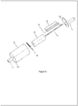
- the first embodiment is presently described with reference to Figures 1 , 2 and 3a, 3b and 4 .
- Carbon particulate matter laden exhaust gases C in enter the CCM through an exhaust inlet pipe 11, which leads into an enclosing chamber 12, provided with an exhaust outlet pipe 13 to discharge the cleaned exhaust gases C out .
- the enclosing chamber 12 is horizontally positioned and is shaped substantially as a hollow cylinder and is referred hereinafter as a first cylinder 14.
- the first cylinder 14 is provided with a downward slope towards the exhaust outlet pipe 13.
- the first cylinder 14 is provided with a front lid 31 and a back lid 32.
- the first cylinder 14 houses a second hollow cylinder 15, having a diameter lesser than the diameter of the first cylinder 14.
- the second cylinder 15 is disposed coaxially within the first cylinder 14. Both the first cylinder 14 and the second cylinder 15 are electrically conducting in nature and are charged with opposing polarities. Plurality of carbon brushes 16 (not shown in the figures) are in communication with the first cylinder 14 and the second cylinder 15 for supply of electric current.
- the first cylinder 14 is negatively charged on its internal surface and the second cylinder 15 is positively charged on its external surface.
- the second cylinder 15 is mounted on a supporting structure assembly 10 which rotates within the first cylinder 14.
- a stationary vertical support member 17 is non-removably attached to the first cylinder 14 and holds the supporting structure assembly 10 at one end.
- the supporting structure assembly 10 comprises of three parallel pipe members designated as an outer member 18, a central member 19 and an inner member 20.
- the central member 19 is disposed axially and non-removably within the second cylinder 15 and thereby provides support to the second cylinder 15.
- the central member 19 is also coupled to a motor 30 mounted on the exterior of the first cylinder 14.
- a wiper strip, designated as first wiper 21, made of a thermo elastomeric polymer material is non-removably affixed to a longitudinal edge of the outer member 18.
- a wiper strip, designated as second wiper 22, made of a thermo elastomeric polymer material is non-removably affixed to a longitudinal edge of the inner member 20.
- An annular space of approximately 1 inches to 3 inches is maintained between the pair of first cylinder 14 and second cylinder 15.
- the rotating supporting structure 10 is coupled to a 12 V DC power source 29 which is electrically connected with HV circuit 28.
- the annular space is charged with 25,000 V at half wave DC to generate a corona discharge between the oppositely charged first cylinder 14 and second cylinder 15, which causes the ionized carbon particles to get deposited on the cylinders. Layers of carbon particles deposited on the charged interior surface of the first cylinder 14 and the charged exterior surface of the second cylinder 15 are cleaned by action of the wipers brushing against them.
- the first wiper 21 gently scrapes off and cleans a layer of carbon particles deposited on the internal surface of the first cylinder 14.
- the second wiper 22 cleans a layer of carbon particles deposited on the external surface of the second cylinder 15.
- the accumulated carbon particles are thus dislodged from the internal surface of the first cylinder 14 and the external surface of the second cylinder 15 and fall to the bottom sloping floor of the enclosing chamber 12 as agglomerated carbon particles.
- the agglomerated carbon particles migrate towards the outlet slope and are discharged from an exhaust outlet pipe 13.
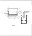
- the exhaust gases C out carrying the agglomerated carbon particles enter a second chamber, designated as separation chamber 23 through the exhaust outlet pipe 13, as depicted in Figure 4 .
- the separation chamber 23 comprises of a cyclone section 24, having a treated outlet pipe 27 to discharge the clean exhaust gases C c , and a collection section 25.
- the agglomerated carbon particles achieve sufficient mass and volume such that they are separated from the exhaust gases in the cyclone section 24.
- the collection section 25 is provided in the form a removable tray 26, and is positioned below the bottom portion of the cyclone section 24, onto which the agglomerated carbon particles get separated and are collected.
- An electronic control unit comprising of a microcontroller system (not shown in the accompanying drawings) is electrically linked to the motor 30 as well as power source 29 for control of the charging and cleaning cycle. After predetermined duration, say every 15 minutes, the charging and cleaning cycles can be alternately switched. It is also possible to programmatically control the cleaning cycle frequency depending on numerous factors such as - on the level of pollution control required, quality and purity of the fuel. Thus there is intermittent cleaning and charging of the cylinders. In alternate embodiments, only a partial surface of the cylinders may be cleaned by controlling the motion of the wipers.
- two coaxial cylinders are used.
- a plurality of pair of two coaxial cylinders may also be used.
- the number of cylinders must hence not be construed as a limiting factor for the present invention.
- the whole unit is of overall dimensions having approximate diameter 3 to 7 inches and approximate length of 7 to 10 inches and fits in a space near the muffler.
- the material of construction for outer and inner cylinders may be a thermally conductive material such as prefereably SS or MS, which can withstand high voltage and high temperature.
- the material of construction for the wipers may be an insulating elastomeric material that is capable of withstanding high temperature, such as Silicon rubber.
- the supporting structure assembly is characterized by a rigid but insulating material, such as a metal construction coated with rubber layer.
- the enclosing chamber 12 is vertically positioned and is shaped substantially as a hollow cylinder and is referred hereinafter as a first cylinder 14.
- the exhaust inlet pipe 11 is preferably positioned in the bottom portion of the first cylinder 14, and the exhaust outlet pipe 13 is positioned at the top portion of the first cylinder 14.
- the second cylinder 15 is disposed coaxially within the first cylinder 14. Both the first cylinder 14 and the second cylinder 15 are electrically conducting in nature and are charged with opposing polarities.
- Plurality of carbon brushes 16 are in communication with the first cylinder 14 and the second cylinder 15 for supply of electric current.
- the first cylinder 14 is negatively charged on its internal surface and the second cylinder 15 is positively charged on its external surface.
- the second cylinder 15 is mounted on a supporting structure assembly 10 which rotates within the first cylinder 14.
- a stationary vertical support member 17 is non-removably attached to the first cylinder 14 and holds the supporting structure assembly 10 at one end.
- the supporting structure assembly 10 comprises of three parallel pipe members designated as an outer member 18, a central member 19 and an inner member 20.
- the central member 19 is disposed axially and non-removably within the second cylinder 15 and thereby provides support to the second cylinder 15.
- the central member 19 is also coupled to a motor 30 mounted on the exterior of the first cylinder 14.
- a wiper strip, designated as first wiper 21, made of a thermo elastomeric polymer material is non-removably affixed to a longitudinal edge of the outer member 18.
- a wiper strip, designated as second wiper 22, made of a thermo elastomeric polymer material is non-removably affixed to a longitudinal edge of the inner member 20.
- An annular space of approximately 1 inches to 3 inches is maintained between the pair of first cylinder 14 and second cylinder 15.
- the rotating supporting structure 10 is coupled to a 12 V DC power source 29 which is electrically connected with HV circuit 28.
- the annular space is charged with 25,000 V at half wave DC to generate a corona discharge between the oppositely charged first cylinder 14 and second cylinder 15, which causes the ionized carbon particles to get deposited on the cylinders. Layers of carbon particles deposited on the charged interior surface of the first cylinder 14 and the charged exterior surface of the second cylinder 15 are cleaned by action of the wipers brushing against them.
- the first wiper 21 gently scrapes off and cleans a layer of carbon particles deposited on the internal surface of the first cylinder 14.
- the second wiper 22 cleans a layer of carbon particles deposited on the external surface of the second cylinder 15.
- the separation chamber 23 is directly integrated with the enclosing chamber 12 in this embodiment.
- the separation chamber 23 comprises of a cyclone section 24 and a collection section 25.
- the agglomerated carbon particles achieve sufficient mass and volume such that they are separated from the exhaust gases in the cyclone section 24.
- the collection section 25 is provided in the form a removable tray 26, and is positioned below the bottom portion of the cyclone section 24, onto which the agglomerated carbon particles get separated and are collected.
- only a partial surface of the cylinders may be cleaned by controlling the motion of the wipers.
- resilient members such as springs may be provided between the wipers.
- an alarm in the form of a visual, audio, or message alert is triggered and the driver of the vehicle is sensitized.
- a message can be sent by telecommunication means to a central server.
- the distribution pipes are housed in a stationary, horizontally positioned enclosing chamber 12, which encloses within it, a duality of rotary metallic discs or plates 33, of opposing polarities, mounted parallely and coaxially on a rotating supporting structure 10.
- the entry of C in into the enclosing chamber 12 is parallel to the discs 33.
- the rotating supporting structure is driven by means such as a pulley and is coupled to a motor 30 mounted on the exterior of the enclosing chamber 12.
- the pair of rotary discs are preferably circular in shape and parallel to each other with an approximate distance of 1 to 3 inches.
- Both the discs designated as a first disc 34 and a second disc 35, are electrically conducting in nature and are charged with opposing polarities.
- Plurality of carbon brushes 16 (not shown in the figure) are in communication with first disc 34 and second disc 35 for supply of electric current.
- the first disc 34 and the second disc 35 are centrally mounted on the rotating, supporting structure assembly 10.
- a wiper strip designated as a first wiper 21, and a wiper strip designated as a second wiper 22, are made of a thermo elastomeric polymer material and are non-removably affixed at a predetermined position of the enclosing chamber.
- the first and second wiper, 21 and 22, are positioned in close contact with the first and second discs, 34 and 35, respectively to scrape off the deposited agglomerated layer of carbon particles.
- the rotating supporting structure 10 is coupled to a 12 V DC motor mounted on the exterior of the enclosing chamber and the space between the rotating discs is charged with 25,000 V at half wave DC to generate a corona discharge between the discs, which causes the ionized carbon particles to agglomerate on the discs.
- the carbon particles that are wiped off from the discs 34 and 35 are collected and discharged in a removable collection box or tray and the exhaust gases may be optionally fed into a cyclone filter.
- the key difference as compared to first and second embodiments is that the charged discs are not stationary during the charging or cleaning cycle and rotate. On the other hand, the wipers do not rotate and are stationary.
- a plurality of discs can be provided.
- a pair of discs has been described as an illustrative example and should not be construed as a limiting factor for the present invention.
- the discs may be constructed of any thermally conducting metallic material that is capable of withstanding high voltage and temperature.
- the device is provided with a slight inclination or gentle downward sloping, such that the separation of agglomerated carbon particles happens due to gravity and there is no need for a cyclone filter.
- only a partial surface of the cylinders may be cleaned by controlling the motion of the discs.
- an alarm in the form of a visual, audio, or a message alert (such as Short Messaging Service SMS alert) is triggered and the driver of the vehicle is sensitized.
- a message can be sent by telecommunication means to a central server.
- the distribution pipes are housed in a stationary, vertically positioned enclosing chamber 12, which encloses within it, a duality of rotary metallic discs or plates 33, of opposing polarities, mounted parallely and coaxially on a rotating supporting structure 10. The entry of C in into the enclosing chamber 12 is perpendicular to the discs 33.
- the rotating supporting structure is driven by means such as a pulley and is coupled to a motor 30 mounted on the exterior of the enclosing chamber 12.
- the pair of rotary discs are preferably circular in shape and parallel to each other with an approximate distance of 1 to 3 inches.
- Both the discs designated as a first disc 34 and a second disc 35, are electrically conducting in nature and are charged with opposing polarities.
- Plurality of carbon brushes 16 are in communication with first disc 34 and second disc 35 for supply of electric current.
- the first disc 34 and the second disc 35 are centrally mounted on the rotating, supporting structure assembly 10.
- a wiper strip, designated as a first wiper 21, and a wiper strip, designated as second wiper 22, made of an thermo elastomeric polymer material are non-removably affixed at a predetermined position of the enclosing chamber 12.
- the first and second wiper, 21 and 22, are positioned in close contact with the first and second disc, 34 and 35, respectively to scrape off the deposited agglomerated layer of carbon particles.
- the rotating supporting structure 10 is coupled to a 12 V DC motor mounted on the exterior of the enclosing chamber and the space between the rotating discs is charged with 25,000 V at half wave DC to generate a corona discharge between the discs, which causes the ionized carbon particles to agglomerate on the discs.
- the carbon particles that are wiped off from the discs 34 and 35 are collected and discharged in a removable collection box or tray and the exhaust gases may be optionally fed into a cyclone filter.
- the key difference of the third and the fourth embodiments as compared to the first and the second embodiments is that the charged discs are not stationary during the charging or cleaning cycle and rotate. On the other hand, the wipers do not rotate and are stationary.
- only a partial surface of the cylinders may be cleaned by controlling the motion of the wipers.
- an alarm in the form of a visual, audio, or message alert is triggered and the driver of the vehicle is sensitized.
- a message can be sent by telecommunication means to a central server.
- the most preferred or the best mode of working the present invention includes the first and the second embodiments.
- the fifth embodiment is presently described with reference to Figure 6 .
- the fifth embodiment referred to as Sucking Tower CCM is suitable for removal of carbon particulate matter from open source pollution areas such as for example, traffic signals, open fields where remains of harvested crop are being burnt.
- a scaled up and modified version of the Coaxial Vertical Double Cylindrical CCM is used.
- the device comprises of the Coaxial Vertical Double Cylindrical CCM housed within in a vertical tower 36.
- An induced draft fan 37 is provided on the top portion of the vertical tower 36 to suck in the carbon particulate matter laden exhaust gases C in .
- a metallic inlet mesh 38 is provided at the entrance of the vertical tower 36 to keep away larger objects from entering the vertical tower 36.
- the carbon particulate matter laden exhaust gases C in are lead into a vertically positioned and substantially hollow cylinder referred hereinafter as a first cylinder 14.
- the second cylinder 15 is disposed coaxially within the first cylinder 14.
- Both the first cylinder 14 and the second cylinder 15 are electrically conducting in nature and are charged with opposing polarities.
- Plurality of carbon brushes 16 are in communication with the first cylinder 14 and the second cylinder 15 for supply of electric current.
- the first cylinder 14 is negatively charged on its internal surface and the second cylinder 15 is positively charged on its external surface.
- the second cylinder 15 is mounted on a supporting structure assembly 10 (not shown in the drawing) which rotates within the first cylinder 14.
- a stationary vertical support member 17 is non-removably attached to the first cylinder 14 and holds the supporting structure assembly 10 at one end.
- the supporting structure assembly 10 comprises of three parallel pipe members designated as an outer member 18, a central member 19 and an inner member 20.
- the central member 19 is disposed axially and non-removably within the second cylinder 15 and thereby provides support to the second cylinder 15.
- the central member 19 is also coupled to a motor 30 mounted on the exterior of the first cylinder 14.
- a wiper strip, designated as first wiper 21, made of a thermo elastomeric polymer material is non-removably affixed to a longitudinal edge of the outer member 18.
- a wiper strip, designated as second wiper 22, made of a thermo elastomeric polymer material is non-removably affixed to a longitudinal edge of the inner member 20.
- An annular space of approximately 1 inches to 3 inches is maintained between the pair of first cylinder 14 and second cylinder 15.
- the rotating supporting structure 10 is coupled to a 12 V DC power source 29 which is electrically connected with HV circuit 28.
- the annular space is charged with 25,000 V at half wave DC to generate a corona discharge between the oppositely charged first cylinder 14 and second cylinder 15, which causes the ionized carbon particles to get deposited on the cylinders. Layers of carbon particles deposited on the charged interior surface of the first cylinder 14 and the charged exterior surface of the second cylinder 15 are cleaned by action of the wipers brushing against them.
- the first wiper 21 gently scrapes off and cleans a layer of carbon particles deposited on the internal surface of the first cylinder 14.
- the second wiper 22 cleans a layer of carbon particles deposited on the external surface of the second cylinder 15.
- the separation chamber 23 is directly integrated with the enclosing chamber 12 in this embodiment.
- the separation chamber 23 comprises of a cyclone section 24 and a collection section 25.
- the agglomerated carbon particles achieve sufficient mass and volume such that they are separated from the exhaust gases in the cyclone section 24.
- the collection section 25 is provided in the form a removable tray 26, and is positioned below the bottom portion of the cyclone section 24, onto which the agglomerated carbon particles get separated and are collected.
- the induced draft fan 37 may be provided at the lower portion of the vertical tower 36.
- a solar power panel is provided on top of the vertical tower 36 to rotate the supporting structure assembly which is coupled to the wiper blades.
- the overall dimensions of the Sucking tower CCM had a height of 5 feet and diameter of 20 inches.
- the overall height of 4 feet included 1 feet at the top for the inlet portion and 1 feet at the lower end for the collection section.
- the Sucking tower CCM may house a plurality of CCMs in any combination and number, in accordance with any of the four embodiments, namely the Coaxial Horizontal Double Cylindrical CCM, the Coaxial Vertical Double Cylindrical CCM, the Coaxial Horizontal Parallel Rotary Discs CCM, or the Coaxial Vertical Parallel Rotary Discs CCM.
- the Sucking tower CCM may be provided in a horizontal configuration.
- Such a configuration may be located on a road divider, like a horizontal pipe, parallel to or along railway tracks.
- the vertical tower 36 itself may function as the first cylinder 14.
- a notification by way of an audio alert, a visual alert, a Short Messaging Service (SMS) alert, or a combination of an audio, visual and a Short Messaging Service (SMS) alert is generated and transmitted to a user or a communication device, when the weight of the agglomerated carbon particles in the collection section reaches a predetermined level.
- SMS Short Messaging Service
- SMS Short Messaging Service
- the communication device may be at least one of a mobile phone, a personal computer, a smart phone, a cellular phone, a personal digital assistant (PDA), a GPS device, a smartbook, a netbook, a notebook, an ultra-mobile personal computer and a wearable computing device.
- PDA personal digital assistant
- Table-2 below provides a summary of the experimental data based on the trials wherein the present invention was coupled with different sources such as vehicles and Diesel Generator (DG) sets.
- Experimental Data - Table - 2 S. No. Vehicle Year of manufacture Test condition Duration of test operation Emissions of heavy vehicle as per BS standards (in gm/km) Carbon particulate matter separated 1.
- the present invention has collected more than the expected quantity of the particulate matter so as to meet the BS standard emission norms for 50 kms.
Landscapes
- Engineering & Computer Science (AREA)
- Chemical & Material Sciences (AREA)
- Mechanical Engineering (AREA)
- General Engineering & Computer Science (AREA)
- Combustion & Propulsion (AREA)
- Chemical Kinetics & Catalysis (AREA)
- Toxicology (AREA)
- Health & Medical Sciences (AREA)
- Processes For Solid Components From Exhaust (AREA)
- Electrostatic Separation (AREA)
- Cyclones (AREA)
- Organic Low-Molecular-Weight Compounds And Preparation Thereof (AREA)
- Glass Compositions (AREA)
- Disintegrating Or Milling (AREA)
Claims (3)
- Vorrichtung für eine Luftreinhaltung, wobei Kohlenstofffeinstaub, der in Abgasen vorhanden ist, die durch die Verbrennung von Kohlenwasserstoffen erzeugt werden, während der Verbrennung agglomeriert, gesammelt und abgeschieden und daran gehindert wird, direkt in die Atmosphäre ausgestoßen zu werden, gekennzeichnet durch gesteuerte Schritte eines Aufladens und eines Reinigens mit einer zuvor bestimmten Dauer und Häufigkeit, die Folgendes umfasst:a) ein Abgaseinlassrohr (11), das in einen ersten Hohlzylinder (14) führt, wobei der erste Hohlzylinder (14) mit einem Abgasauslassrohr (13), einem vorderen Deckel (31), einem hinteren Deckel (32) versehen ist,
wobei der erste Hohlzylinder (14) eine elektrisch leitende Beschaffenheit aufweist;b) einen zweiten Zylinder (15), der innerhalb des ersten Hohlzylinders (14) koaxial eingerichtet ist, um einen ringförmigen Raum mit zuvor bestimmtem Abstand auszubilden,
wobei der Zylinder (15) eine elektrisch leitende Beschaffenheit aufweist;c) mehrere Kohlebürsten (16) in Verbindung mit dem ersten Zylinder (14) und dem zweiten Zylinder (15),d) eine Hochspannungsstromquelle (29), die mit den mehreren Kohlebürsten (16) verbunden ist, die in der Lage ist, eine vorgeschriebene Hochspannung zwischen dem ersten Zylinder (14) und dem zweiten Zylinder (15) anzulegen und den ersten Zylinder und den zweiten Zylinder mit entgegengesetzten Polaritäten aufzuladen, um eine Koronaentladung zu erzeugen,e) eine Stützstrukturanordnung (16), die innerhalb des ersten Zylinders (14) drehbar eingerichtet ist, wobei die Stützstrukturanordnung (16) ferner aus drei parallelen Rohrelementen besteht, die als ein äußeres Element (18), ein zentrales Element (19) und ein inneres Element (20) derart bezeichnet werden, dass das zentrale Element (19) innerhalb des zweiten Zylinders (15) axial und nicht lösbar eingerichtet ist,f) eine Stromquelle (Motor (30)), die an der Außenseite des ersten Zylinders montiert und mit dem zentralen Element (19) zum Antreiben der sich drehenden Bewegung der Stützstrukturanordnung (16) gekoppelt ist,g) ein stationäres vertikales Stützelement (17), das an dem ersten Zylinder (14) nicht lösbar befestigt und an einem Ende mit der Stützstrukturanordnung (16) verbunden ist,h) einen ersten Abstreifer (21), der an einer Längskante des äußeren Elements (18) nicht lösbar angebracht ist und in Berührung mit der Außenoberfläche des zweiten Zylinders steht,i) einen zweiten Abstreifer (22), der an einer Längskante des inneren Elements (20) nicht lösbar angebracht ist und in Berührung mit der Innenoberfläche des Zylinders steht,
wobei der erste Abstreifer (21) und der zweite Abstreifer (22) aus einem thermoelastomerischen Polymermaterial bestehen,j) eine Abscheidekammer (23), die mit dem ersten Zylinder (14) durch das Abgasauslassrohr (13) verbunden ist oder mit dem unteren Abschnitt des ersten Zylinders (14) einstückig gekoppelt ist, wobei die Abscheidekammer (23) ferner einen Zyklonbereich (24), einen Sammelbereich (25) und ein Auslassrohr (27) umfasst;
wobei der Sammelbereich (25) ferner aus einer lösbaren Schale (26) besteht, die an dem unteren Abschnitt positioniert und mit dem Zyklonbereich (24) gekoppelt ist, und wobei das Auslassrohr (27) mit dem oberen Abschnitt des Zyklonbereichs (24) zum Ablassen von sauberen Abgasen Cc verbunden ist;k) eine elektronische Steuereinheit, die aus einem Mikrocontrollersystem besteht, das mit dem Motor (30) und der Stromquelle (29) für eine Steuerung des Auflade- und Reinigungszyklus mit zuvor bestimmter Dauer und zuvor bestimmter Häufigkeit elektrisch verbunden ist;wobei die Umschließungskammer (12) horizontal und parallel zu dem Zufluss des Abgases positioniert ist, der erste Zylinder (14) und der zweite Zylinder (15) stationär sind und der erste Abstreifer (21) und der zweite Abstreifer (22) sich drehen. - Vorrichtung für die Luftreinhaltung,
wobei Kohlenstofffeinstaub, der in Abgasen vorhanden ist, die durch die Verbrennung von Kohlenwasserstoffen erzeugt werden, während der Verbrennung agglomeriert, gesammelt und abgeschieden und daran gehindert wird, direkt in die Atmosphäre ausgestoßen zu werden, geeignet dafür, dass sie durch gesteuerte Schritte des Aufladens und des Reinigens mit zuvor bestimmter Dauer und Häufigkeit gekennzeichnet ist, die Folgendes umfasst:a) eine stationäre, horizontal positionierte Umschließungskammer (12), die innerhalb derselben eine Dualität von Drehmetallscheiben 33 umschließt, die aus einer ersten Scheibe und einer zweiten Scheibe mit entgegengesetzten Polaritäten besteht, die auf einer sich drehenden Stützstruktur (10) parallel und koaxial montiert sind,
wobei die Dualität von Drehmetallscheiben 33 eine elektrisch leitende Beschaffenheit aufweist und die Dualität von Drehmetallscheiben 33 positioniert ist, um einen ringförmigen Raum mit zuvor bestimmtem Abstand auszubilden,b) mehrere Kohlebürsten (16) in Verbindung mit der ersten Scheibe und der zweiten Scheibe,c) eine Hochspannungsstromquelle (29), die mit den mehreren Kohlebürsten (16) verbunden ist, die in der Lage ist, eine vorgeschriebene Hochspannung zwischen der ersten Scheibe und der zweiten Scheibe anzulegen und die erste Scheibe und die zweite Scheibe mit entgegengesetzten Polaritäten aufzuladen, um eine Koronaentladung zu erzeugen,d) eine Stützstrukturanordnung (16), die innerhalb der Umschließungskammer (12) drehbar eingerichtet ist und ferner aus einer drehbaren Welle besteht, auf der die mehreren Drehscheiben 33 für eine Drehung in einer Ebene senkrecht zu der Welle fest montiert sind,e) eine Stromquelle (Motor (30)), die an der Außenseite der Umschließungskammer (12) zum Antreiben der sich drehenden Bewegung der Stützstrukturanordnung (16) montiert ist,f) ein stationäres vertikales Stützelement (17), das an einem Ende an der Stützstrukturanordnung (16) nicht lösbar befestigt ist,g) einen ersten Abstreifer (21), der an der Stützstrukturanordnung (16) nicht lösbar angebracht ist und mit einer Oberfläche einer ersten Scheibe in Berührung steht,h) einen zweiten Abstreifer (22), der an der Stützstrukturanordnung (16) nicht lösbar angebracht ist und mit einer Oberfläche einer zweiten Scheibe in Berührung steht,
wobei der erste Abstreifer (21) und der zweite Abstreifer (22) aus einem thermoelastomerischen Polymermaterial bestehen,i) eine Abscheidekammer (23), die mit der Umschließungskammer (12) durch das Abgasauslassrohr (13) verbunden ist oder mit dem unteren Abschnitt des ersten Zylinders (14) einstückig gekoppelt ist, wobei die Abscheidekammer (23) ferner einen Zyklonbereich (24), einen Sammelbereich (25) und ein Auslassrohr (26) umfasst;
wobei der Sammelbereich (25) ferner aus einer lösbaren Schale (26) besteht, die an dem unteren Abschnitt positioniert und mit dem Zyklonbereich (24) gekoppelt ist, und wobei das Auslassrohr (26) mit dem oberen Abschnitt des Zyklonbereichs (24) zum Ablassen von sauberen Abgasen Cc verbunden ist;j) eine elektronische Steuereinheit, die aus einem Mikrocontrollersystem besteht, das mit dem Motor (30) und der Stromquelle (29) für eine Steuerung des Auflade- und Reinigungszyklus mit zuvor bestimmter Dauer und zuvor bestimmter Häufigkeit elektrisch verbunden ist;wobei die Umschließungskammer (12) stationär und horizontal positioniert ist und die erste Scheibe und die zweite Scheibe sich in einer Ebene senkrecht zu dem Zufluss des Abgases drehen und der erste Abstreifer (21) und der zweite Abstreifer (22) stationär sind. - Vorrichtung für die Luftreinhaltung,
wobei Kohlenstofffeinstaub, der in Abgasen vorhanden ist, die in einer Verschmutzung durch eine öffentliche Quelle erzeugt werden, agglomeriert, gesammelt und abgeschieden wird und daran gehindert wird, direkt in die Atmosphäre ausgestoßen zu werden, gekennzeichnet durch gesteuerte Schritte des Aufladens und des Reinigens mit zuvor bestimmter Dauer und Häufigkeit, die Folgendes umfasst:a) einen vertikalen Turm (36), der mit einem Einlassgitter 38, einem Saugzugventilator 37 und einem ersten Hohlzylinder (14) versehen ist, wobei der erste Hohlzylinder (14) eine elektrisch leitende Beschaffenheit aufweist und in der zentralen Position des vertikalen Turms (36) untergebracht ist;b) einen zweiten Zylinder (15), der innerhalb des ersten Hohlzylinders (14) koaxial eingerichtet ist, um einen ringförmigen Raum mit zuvor bestimmtem Abstand auszubilden, wobei der Zylinder (15) eine elektrisch leitende Beschaffenheit aufweist;c) mehrere Kohlebürsten (16) in Verbindung mit dem ersten Zylinder (14) und dem zweiten Zylinder (15),d) eine Hochspannungsstromquelle (29), die mit den mehreren Kohlebürsten (16) verbunden ist, die in der Lage ist, eine vorgeschriebene Hochspannung zwischen dem ersten Zylinder (14) und dem zweiten Zylinder (15) anzulegen und den ersten Zylinder (14) und den zweiten Zylinder (15) mit entgegengesetzten Polaritäten aufzuladen, um eine Koronaentladung zu erzeugen,e) eine Stützstrukturanordnung (16), die innerhalb des ersten Zylinders (14) drehbar eingerichtet ist, wobei die Stützstrukturanordnung (16) ferner aus drei parallelen Rohrelementen besteht, die als ein äußeres Element (18), ein zentrales Element (19) und ein inneres Element (20) derart bezeichnet werden, dass das zentrale Element (19) innerhalb des zweiten Zylinders (15) axial und nicht lösbar eingerichtet ist,f) eine Stromquelle (Motor (30)), die mit dem zentralen Element (19) zum Antreiben der sich drehenden Bewegung der Stützstrukturanordnung (16) gekoppelt ist,g) ein stationäres vertikales Stützelement (17), das an dem ersten Zylinder (14) nicht lösbar befestigt und an einem Ende mit der Stützstrukturanordnung (16) verbunden ist,h) einen ersten Abstreifer (21), der an einer Längskante des äußeren Elements (18) nicht lösbar angebracht ist und in Berührung mit der Außenoberfläche des zweiten Zylinders steht,i) einen zweiten Abstreifer (22), der an einer Längskante des inneren Elements (20) nicht lösbar angebracht ist und in Berührung mit der Innenoberfläche des Zylinders steht, wobei der erste Abstreifer (21) und der zweite Abstreifer (22) aus einem thermoelastomerischen Polymermaterial bestehen,a) eine Abscheidekammer (23), die mit dem unteren Abschnitt des ersten Zylinders (14) einstückig gekoppelt ist, wobei die Abscheidekammer (23) ferner einen Zyklonbereich (24), einen Sammelbereich (25) und ein Auslassrohr (27) umfasst; wobei der Sammelbereich (25) ferner aus einer lösbaren Schale (26) besteht, die an dem unteren Abschnitt positioniert und mit dem Zyklonbereich (24) gekoppelt ist, und das Auslassrohr (27) mit dem oberen Abschnitt des Zyklonbereichs (24) zum Ablassen von sauberen Abgasen Cc verbunden ist;j) eine elektronische Steuereinheit, die aus einem Mikrocontrollersystem besteht, das mit dem Motor (30) und der Stromquelle (29) für eine Steuerung des Auflade- und Reinigungszyklus mit zuvor bestimmter Dauer und zuvor bestimmter Häufigkeit elektrisch verbunden ist;wobei der Ansaugturm (36) vertikal und senkrecht zu dem Zufluss des Abgases positioniert ist, der erste Zylinder (14) und der zweite Zylinder (15) stationär sind und der erste Abstreifer (21) und der zweite Abstreifer (22) sich drehen.
Priority Applications (3)
| Application Number | Priority Date | Filing Date | Title |
|---|---|---|---|
| HRP20210852TT HRP20210852T1 (hr) | 2016-05-13 | 2017-05-09 | Separator ugljika |
| PL17795753T PL3455472T3 (pl) | 2016-05-13 | 2017-05-09 | Separator węgla |
| RS20210680A RS61962B1 (sr) | 2016-05-13 | 2017-05-09 | Separator ugljenika |
Applications Claiming Priority (2)
| Application Number | Priority Date | Filing Date | Title |
|---|---|---|---|
| IN201621016689 | 2016-05-13 | ||
| PCT/IN2017/050168 WO2017195217A1 (en) | 2016-05-13 | 2017-05-09 | Carbon cutter machine |
Publications (3)
| Publication Number | Publication Date |
|---|---|
| EP3455472A1 EP3455472A1 (de) | 2019-03-20 |
| EP3455472A4 EP3455472A4 (de) | 2019-12-18 |
| EP3455472B1 true EP3455472B1 (de) | 2021-03-03 |
Family
ID=60266679
Family Applications (1)
| Application Number | Title | Priority Date | Filing Date |
|---|---|---|---|
| EP17795753.7A Active EP3455472B1 (de) | 2016-05-13 | 2017-05-09 | Kohlenstoffabscheider |
Country Status (14)
| Country | Link |
|---|---|
| US (1) | US10961885B2 (de) |
| EP (1) | EP3455472B1 (de) |
| JP (1) | JP2019516909A (de) |
| CN (1) | CN109072743B (de) |
| CY (1) | CY1124351T1 (de) |
| DK (1) | DK3455472T3 (de) |
| ES (1) | ES2874724T3 (de) |
| HR (1) | HRP20210852T1 (de) |
| HU (1) | HUE054651T2 (de) |
| PL (1) | PL3455472T3 (de) |
| PT (1) | PT3455472T (de) |
| RS (1) | RS61962B1 (de) |
| SG (1) | SG11201903423TA (de) |
| WO (1) | WO2017195217A1 (de) |
Families Citing this family (5)
| Publication number | Priority date | Publication date | Assignee | Title |
|---|---|---|---|---|
| CN110080857B (zh) * | 2019-05-22 | 2021-03-30 | 南通炜途汽车技术有限公司 | 一种汽车尾气除尘装置 |
| DE102019003684B4 (de) * | 2019-05-27 | 2024-09-12 | Siempelkamp Maschinen- Und Anlagenbau Gmbh | Vorrichtung und Verfahren zur Konfektionierung von Werkstoffplatten |
| CN111255544B (zh) * | 2020-02-14 | 2021-08-24 | 台州三元车辆净化器有限公司 | 一种车辆尾气净化防堵装置 |
| CN113217141A (zh) * | 2020-08-21 | 2021-08-06 | 李雨阳 | 柴油机尾气净化器 |
| CN113210379B (zh) * | 2021-05-23 | 2024-06-21 | 中广核新能源六安有限公司 | 用于滑环室碳粉的自动清洁装置 |
Family Cites Families (15)
| Publication number | Priority date | Publication date | Assignee | Title |
|---|---|---|---|---|
| CH437919A (de) * | 1966-05-06 | 1967-06-15 | G A Messen Jaschin Fa | Einrichtung zum Reinigen von Auspuffgas mittels Elektrofilter |
| US4362016A (en) * | 1979-10-15 | 1982-12-07 | Papadopulos Stephen C | Pollution control device for automobile exhaust |
| US4539022A (en) * | 1984-03-30 | 1985-09-03 | General Electric Company | Rotating disk electrostatic precipitator with removable uniform flow duct |
| DE3707938A1 (de) * | 1987-03-12 | 1988-09-22 | Paul J M Haufe | Vorrichtung zur aufbereitung, insbesondere filtrierung, der raumluft |
| US5429669A (en) * | 1994-07-12 | 1995-07-04 | Chang; Chin-Chu | Electrostatic precipitator |
| US5580368A (en) * | 1995-02-22 | 1996-12-03 | Su-Ying R. Lu | Exhaust gas cleaning device |
| US6221136B1 (en) | 1998-11-25 | 2001-04-24 | Msp Corporation | Compact electrostatic precipitator for droplet aerosol collection |
| CN2400580Y (zh) * | 1999-12-17 | 2000-10-11 | 薛晓峰 | 燃油设备尾气消音除尘装置 |
| EP1829614A1 (de) | 2006-03-02 | 2007-09-05 | Technische Universiteit Delft | Verfahren zur Entfernung von Rußflocken, Feinstaub und Brennkraftmaschinen-Abgaspartikel, Teilchensammelvorrichtung zur Verwendung in diesem Verfahren und Verwendung der Teilchensammelvorrichtung zur Erzeugung eines statischen elektrischen Felds |
| KR100865152B1 (ko) * | 2007-07-27 | 2008-10-24 | 한국기계연구원 | 원심력과 정전기력을 이용한 매연저감장치 및 이를 이용한매연저감방법 |
| CN101532412B (zh) * | 2008-03-10 | 2011-07-06 | 王凯 | 一种汽车尾气净化方法及其汽车尾气净化系统 |
| CN201265440Y (zh) * | 2008-10-11 | 2009-07-01 | 贾元华 | 高效组合柴油机微粒捕集器 |
| JP6062660B2 (ja) * | 2012-05-15 | 2017-01-18 | 臼井国際産業株式会社 | 重油より低質な燃料を使用する大排気量船舶用ディーゼルエンジン排ガス処理装置 |
| KR101383309B1 (ko) | 2012-08-08 | 2014-04-09 | 한국기계연구원 | 전기집진방식 매연여과장치를 이용한 디젤엔진의 매연여과시스템 |
| CN103585844B (zh) * | 2013-09-24 | 2015-06-10 | 何宗彦 | 多功能电子口罩 |
-
2017
- 2017-05-09 RS RS20210680A patent/RS61962B1/sr unknown
- 2017-05-09 ES ES17795753T patent/ES2874724T3/es active Active
- 2017-05-09 PL PL17795753T patent/PL3455472T3/pl unknown
- 2017-05-09 DK DK17795753.7T patent/DK3455472T3/da active
- 2017-05-09 US US16/300,952 patent/US10961885B2/en active Active
- 2017-05-09 PT PT177957537T patent/PT3455472T/pt unknown
- 2017-05-09 WO PCT/IN2017/050168 patent/WO2017195217A1/en not_active Ceased
- 2017-05-09 HU HUE17795753A patent/HUE054651T2/hu unknown
- 2017-05-09 JP JP2019512046A patent/JP2019516909A/ja active Pending
- 2017-05-09 CN CN201780027123.6A patent/CN109072743B/zh active Active
- 2017-05-09 SG SG11201903423TA patent/SG11201903423TA/en unknown
- 2017-05-09 HR HRP20210852TT patent/HRP20210852T1/hr unknown
- 2017-05-09 EP EP17795753.7A patent/EP3455472B1/de active Active
-
2021
- 2021-06-01 CY CY20211100474T patent/CY1124351T1/el unknown
Non-Patent Citations (1)
| Title |
|---|
| None * |
Also Published As
| Publication number | Publication date |
|---|---|
| HUE054651T2 (hu) | 2021-09-28 |
| EP3455472A4 (de) | 2019-12-18 |
| CN109072743A (zh) | 2018-12-21 |
| JP2019516909A (ja) | 2019-06-20 |
| RS61962B1 (sr) | 2021-07-30 |
| EP3455472A1 (de) | 2019-03-20 |
| HRP20210852T1 (hr) | 2021-07-09 |
| US20200318512A1 (en) | 2020-10-08 |
| PT3455472T (pt) | 2021-06-03 |
| ES2874724T3 (es) | 2021-11-05 |
| PL3455472T3 (pl) | 2022-02-28 |
| US10961885B2 (en) | 2021-03-30 |
| WO2017195217A1 (en) | 2017-11-16 |
| CY1124351T1 (el) | 2022-07-22 |
| DK3455472T3 (da) | 2021-06-07 |
| CN109072743B (zh) | 2021-03-30 |
| SG11201903423TA (en) | 2019-05-30 |
Similar Documents
| Publication | Publication Date | Title |
|---|---|---|
| US10961885B2 (en) | Carbon cutter machine | |
| US9488382B2 (en) | Electronic air cleaners and associated systems and methods | |
| US8771600B2 (en) | Electrostatic filter and non-thermal plasma system for air pollution control of hydrocarbon combustion engines | |
| CN113574324A (zh) | 塔式空气净化装置及其空气净化方法 | |
| CN203533744U (zh) | 中央空调、空气净化设备及空气净化系统 | |
| CN104501311A (zh) | 一种室内空气净化方法及其装置 | |
| CN205299689U (zh) | 一种环保油烟净化装置 | |
| CN104390271B (zh) | 等离子放电结合改性分子筛的空气净化装置及其使用方法 | |
| CN110022982A (zh) | 静电颗粒过滤 | |
| CN207599903U (zh) | 一种安装在楼宇中央新风机组内的ifd空气净化装置 | |
| JP2014522310A (ja) | 空気清浄装置及びその方法 | |
| CN101455929A (zh) | 高风速隧道空气电气集尘系统 | |
| CN109604062B (zh) | 静电除尘反应器设计方法及室内除尘设备 | |
| WO2020083174A1 (zh) | 车载尾气和空气除尘系统、车辆及方法 | |
| CN103615770A (zh) | 空气净化装置 | |
| KR100634490B1 (ko) | 양극성 복합 정전유전체 응집 방식 미세입자 포집 장치 | |
| CN207615020U (zh) | 大气悬浮颗粒物收集器 | |
| WO2014139051A1 (zh) | 大流量空气净化设备 | |
| CN106975351A (zh) | 一种基于静电除尘技术和光催化技术的空气净化装置 | |
| CN108939770B (zh) | 原位消除室外新风或室内空气静电除尘过程伴生臭氧的方法与装置 | |
| CN206556145U (zh) | 一种复合空气净化器 | |
| WO2020216370A1 (zh) | 一种VOCs气体处理装置及方法 | |
| CN201254070Y (zh) | 一种车内空气净化装置 | |
| KR20200108388A (ko) | 타워형 공기정화장치 및 이의 공기정화 방법 | |
| CN203240669U (zh) | 复合式空气净化除尘装置 |
Legal Events
| Date | Code | Title | Description |
|---|---|---|---|
| STAA | Information on the status of an ep patent application or granted ep patent |
Free format text: STATUS: THE INTERNATIONAL PUBLICATION HAS BEEN MADE |
|
| PUAI | Public reference made under article 153(3) epc to a published international application that has entered the european phase |
Free format text: ORIGINAL CODE: 0009012 |
|
| STAA | Information on the status of an ep patent application or granted ep patent |
Free format text: STATUS: REQUEST FOR EXAMINATION WAS MADE |
|
| 17P | Request for examination filed |
Effective date: 20181126 |
|
| AK | Designated contracting states |
Kind code of ref document: A1 Designated state(s): AL AT BE BG CH CY CZ DE DK EE ES FI FR GB GR HR HU IE IS IT LI LT LU LV MC MK MT NL NO PL PT RO RS SE SI SK SM TR |
|
| AX | Request for extension of the european patent |
Extension state: BA ME |
|
| DAV | Request for validation of the european patent (deleted) | ||
| DAX | Request for extension of the european patent (deleted) | ||
| A4 | Supplementary search report drawn up and despatched |
Effective date: 20191114 |
|
| RIC1 | Information provided on ipc code assigned before grant |
Ipc: F01N 3/021 20060101ALI20191108BHEP Ipc: F01N 3/00 20060101AFI20191108BHEP Ipc: F01N 3/24 20060101ALI20191108BHEP Ipc: F01N 3/01 20060101ALI20191108BHEP Ipc: F01N 3/08 20060101ALI20191108BHEP |
|
| GRAP | Despatch of communication of intention to grant a patent |
Free format text: ORIGINAL CODE: EPIDOSNIGR1 |
|
| STAA | Information on the status of an ep patent application or granted ep patent |
Free format text: STATUS: GRANT OF PATENT IS INTENDED |
|
| INTG | Intention to grant announced |
Effective date: 20200914 |
|
| GRAS | Grant fee paid |
Free format text: ORIGINAL CODE: EPIDOSNIGR3 |
|
| GRAA | (expected) grant |
Free format text: ORIGINAL CODE: 0009210 |
|
| STAA | Information on the status of an ep patent application or granted ep patent |
Free format text: STATUS: THE PATENT HAS BEEN GRANTED |
|
| AK | Designated contracting states |
Kind code of ref document: B1 Designated state(s): AL AT BE BG CH CY CZ DE DK EE ES FI FR GB GR HR HU IE IS IT LI LT LU LV MC MK MT NL NO PL PT RO RS SE SI SK SM TR |
|
| REG | Reference to a national code |
Ref country code: GB Ref legal event code: FG4D |
|
| REG | Reference to a national code |
Ref country code: AT Ref legal event code: REF Ref document number: 1367437 Country of ref document: AT Kind code of ref document: T Effective date: 20210315 Ref country code: CH Ref legal event code: EP |
|
| REG | Reference to a national code |
Ref country code: DE Ref legal event code: R096 Ref document number: 602017033941 Country of ref document: DE |
|
| REG | Reference to a national code |
Ref country code: IE Ref legal event code: FG4D |
|
| REG | Reference to a national code |
Ref country code: HR Ref legal event code: TUEP Ref document number: P20210852 Country of ref document: HR |
|
| REG | Reference to a national code |
Ref country code: RO Ref legal event code: EPE |
|
| REG | Reference to a national code |
Ref country code: PT Ref legal event code: SC4A Ref document number: 3455472 Country of ref document: PT Date of ref document: 20210603 Kind code of ref document: T Free format text: AVAILABILITY OF NATIONAL TRANSLATION Effective date: 20210531 |
|
| REG | Reference to a national code |
Ref country code: DK Ref legal event code: T3 Effective date: 20210601 |
|
| REG | Reference to a national code |
Ref country code: FI Ref legal event code: FGE |
|
| RAP2 | Party data changed (patent owner data changed or rights of a patent transferred) |
Owner name: PI GREEN INNOVATIONS PRIVATE LIMITED |
|
| REG | Reference to a national code |
Ref country code: NL Ref legal event code: FP |
|
| REG | Reference to a national code |
Ref country code: SE Ref legal event code: TRGR |
|
| REG | Reference to a national code |
Ref country code: NL Ref legal event code: PD Owner name: PI GREEN INNOVATIONS PRIVATE LIMITED; IN Free format text: DETAILS ASSIGNMENT: CHANGE OF OWNER(S), ASSIGNMENT; FORMER OWNER NAME: P I GREEN TECH SOLUTIONS Effective date: 20210602 |
|
| REG | Reference to a national code |
Ref country code: HR Ref legal event code: ODRP Ref document number: P20210852 Country of ref document: HR Payment date: 20210601 Year of fee payment: 5 |
|
| REG | Reference to a national code |
Ref country code: DE Ref legal event code: R081 Ref document number: 602017033941 Country of ref document: DE Owner name: PI GREEN INNOVATIONS PTE LTD, IN Free format text: FORMER OWNER: P I GREEN TECH SOLUTIONS, KALYANINAGAR, PUNE, IN |
|
| REG | Reference to a national code |
Ref country code: HR Ref legal event code: T1PR Ref document number: P20210852 Country of ref document: HR |
|
| REG | Reference to a national code |
Ref country code: LT Ref legal event code: MG9D |
|
| REG | Reference to a national code |
Ref country code: SK Ref legal event code: T3 Ref document number: E 37269 Country of ref document: SK |
|
| REG | Reference to a national code |
Ref country code: NO Ref legal event code: T2 Effective date: 20210303 |
|
| REG | Reference to a national code |
Ref country code: GR Ref legal event code: EP Ref document number: 20210401450 Country of ref document: GR Effective date: 20210709 |
|
| PG25 | Lapsed in a contracting state [announced via postgrant information from national office to epo] |
Ref country code: LT Free format text: LAPSE BECAUSE OF FAILURE TO SUBMIT A TRANSLATION OF THE DESCRIPTION OR TO PAY THE FEE WITHIN THE PRESCRIBED TIME-LIMIT Effective date: 20210303 |
|
| REG | Reference to a national code |
Ref country code: GB Ref legal event code: 732E Free format text: REGISTERED BETWEEN 20210708 AND 20210714 |
|
| REG | Reference to a national code |
Ref country code: HU Ref legal event code: AG4A Ref document number: E054651 Country of ref document: HU |
|
| PG25 | Lapsed in a contracting state [announced via postgrant information from national office to epo] |
Ref country code: SM Free format text: LAPSE BECAUSE OF FAILURE TO SUBMIT A TRANSLATION OF THE DESCRIPTION OR TO PAY THE FEE WITHIN THE PRESCRIBED TIME-LIMIT Effective date: 20210303 Ref country code: EE Free format text: LAPSE BECAUSE OF FAILURE TO SUBMIT A TRANSLATION OF THE DESCRIPTION OR TO PAY THE FEE WITHIN THE PRESCRIBED TIME-LIMIT Effective date: 20210303 |
|
| REG | Reference to a national code |
Ref country code: ES Ref legal event code: FG2A Ref document number: 2874724 Country of ref document: ES Kind code of ref document: T3 Effective date: 20211105 |
|
| REG | Reference to a national code |
Ref country code: BE Ref legal event code: PD Owner name: PI GREEN INNOVATIONS PRIVATE LIMITED; IN Free format text: DETAILS ASSIGNMENT: CHANGE OF OWNER(S), ASSIGNMENT Effective date: 20211012 |
|
| PG25 | Lapsed in a contracting state [announced via postgrant information from national office to epo] |
Ref country code: IS Free format text: LAPSE BECAUSE OF FAILURE TO SUBMIT A TRANSLATION OF THE DESCRIPTION OR TO PAY THE FEE WITHIN THE PRESCRIBED TIME-LIMIT Effective date: 20210703 |
|
| REG | Reference to a national code |
Ref country code: DE Ref legal event code: R097 Ref document number: 602017033941 Country of ref document: DE |
|
| PLBE | No opposition filed within time limit |
Free format text: ORIGINAL CODE: 0009261 |
|
| STAA | Information on the status of an ep patent application or granted ep patent |
Free format text: STATUS: NO OPPOSITION FILED WITHIN TIME LIMIT |
|
| REG | Reference to a national code |
Ref country code: BE Ref legal event code: PD Owner name: PI GREEN INNOVATIONS PRIVATE LIMITED; IN Free format text: DETAILS ASSIGNMENT: CHANGE OF OWNER(S), ASSIGNMENT; FORMER OWNER NAME: P I GREEN TECH SOLUTIONS Effective date: 20211012 |
|
| PG25 | Lapsed in a contracting state [announced via postgrant information from national office to epo] |
Ref country code: MC Free format text: LAPSE BECAUSE OF FAILURE TO SUBMIT A TRANSLATION OF THE DESCRIPTION OR TO PAY THE FEE WITHIN THE PRESCRIBED TIME-LIMIT Effective date: 20210303 Ref country code: AL Free format text: LAPSE BECAUSE OF FAILURE TO SUBMIT A TRANSLATION OF THE DESCRIPTION OR TO PAY THE FEE WITHIN THE PRESCRIBED TIME-LIMIT Effective date: 20210303 |
|
| 26N | No opposition filed |
Effective date: 20211206 |
|
| PG25 | Lapsed in a contracting state [announced via postgrant information from national office to epo] |
Ref country code: SI Free format text: LAPSE BECAUSE OF FAILURE TO SUBMIT A TRANSLATION OF THE DESCRIPTION OR TO PAY THE FEE WITHIN THE PRESCRIBED TIME-LIMIT Effective date: 20210303 |
|
| PG25 | Lapsed in a contracting state [announced via postgrant information from national office to epo] |
Ref country code: IS Free format text: LAPSE BECAUSE OF FAILURE TO SUBMIT A TRANSLATION OF THE DESCRIPTION OR TO PAY THE FEE WITHIN THE PRESCRIBED TIME-LIMIT Effective date: 20210703 |
|
| REG | Reference to a national code |
Ref country code: HR Ref legal event code: ODRP Ref document number: P20210852 Country of ref document: HR Payment date: 20220429 Year of fee payment: 6 |
|
| REG | Reference to a national code |
Ref country code: HR Ref legal event code: ODRP Ref document number: P20210852 Country of ref document: HR Payment date: 20230508 Year of fee payment: 7 |
|
| P01 | Opt-out of the competence of the unified patent court (upc) registered |
Effective date: 20230509 |
|
| P02 | Opt-out of the competence of the unified patent court (upc) changed |
Effective date: 20230602 |
|
| PG25 | Lapsed in a contracting state [announced via postgrant information from national office to epo] |
Ref country code: MK Free format text: LAPSE BECAUSE OF FAILURE TO SUBMIT A TRANSLATION OF THE DESCRIPTION OR TO PAY THE FEE WITHIN THE PRESCRIBED TIME-LIMIT Effective date: 20210303 |
|
| REG | Reference to a national code |
Ref country code: HR Ref legal event code: ODRP Ref document number: P20210852 Country of ref document: HR Payment date: 20240425 Year of fee payment: 8 |
|
| PG25 | Lapsed in a contracting state [announced via postgrant information from national office to epo] |
Ref country code: MT Free format text: LAPSE BECAUSE OF FAILURE TO SUBMIT A TRANSLATION OF THE DESCRIPTION OR TO PAY THE FEE WITHIN THE PRESCRIBED TIME-LIMIT Effective date: 20210303 |
|
| REG | Reference to a national code |
Ref country code: HR Ref legal event code: ODRP Ref document number: P20210852 Country of ref document: HR Payment date: 20250504 Year of fee payment: 9 |
|
| PGFP | Annual fee paid to national office [announced via postgrant information from national office to epo] |
Ref country code: NL Payment date: 20250521 Year of fee payment: 9 |
|
| PGFP | Annual fee paid to national office [announced via postgrant information from national office to epo] |
Ref country code: FI Payment date: 20250526 Year of fee payment: 9 |
|
| PGFP | Annual fee paid to national office [announced via postgrant information from national office to epo] |
Ref country code: PL Payment date: 20250505 Year of fee payment: 9 Ref country code: DE Payment date: 20250429 Year of fee payment: 9 |
|
| PGFP | Annual fee paid to national office [announced via postgrant information from national office to epo] |
Ref country code: GB Payment date: 20250527 Year of fee payment: 9 Ref country code: DK Payment date: 20250526 Year of fee payment: 9 |
|
| PGFP | Annual fee paid to national office [announced via postgrant information from national office to epo] |
Ref country code: RS Payment date: 20250505 Year of fee payment: 9 Ref country code: HU Payment date: 20250523 Year of fee payment: 9 Ref country code: NO Payment date: 20250523 Year of fee payment: 9 |
|
| PGFP | Annual fee paid to national office [announced via postgrant information from national office to epo] |
Ref country code: LU Payment date: 20250521 Year of fee payment: 9 Ref country code: BE Payment date: 20250521 Year of fee payment: 9 Ref country code: IT Payment date: 20250527 Year of fee payment: 9 |
|
| PGFP | Annual fee paid to national office [announced via postgrant information from national office to epo] |
Ref country code: HR Payment date: 20250504 Year of fee payment: 9 |
|
| PGFP | Annual fee paid to national office [announced via postgrant information from national office to epo] |
Ref country code: PT Payment date: 20250502 Year of fee payment: 9 Ref country code: LV Payment date: 20250514 Year of fee payment: 9 |
|
| PGFP | Annual fee paid to national office [announced via postgrant information from national office to epo] |
Ref country code: FR Payment date: 20250528 Year of fee payment: 9 |
|
| PGFP | Annual fee paid to national office [announced via postgrant information from national office to epo] |
Ref country code: GR Payment date: 20250523 Year of fee payment: 9 Ref country code: BG Payment date: 20250521 Year of fee payment: 9 |
|
| PGFP | Annual fee paid to national office [announced via postgrant information from national office to epo] |
Ref country code: CH Payment date: 20250601 Year of fee payment: 9 |
|
| PGFP | Annual fee paid to national office [announced via postgrant information from national office to epo] |
Ref country code: AT Payment date: 20250522 Year of fee payment: 9 Ref country code: RO Payment date: 20250505 Year of fee payment: 9 |
|
| PGFP | Annual fee paid to national office [announced via postgrant information from national office to epo] |
Ref country code: TR Payment date: 20250505 Year of fee payment: 9 Ref country code: SK Payment date: 20250505 Year of fee payment: 9 |
|
| PGFP | Annual fee paid to national office [announced via postgrant information from national office to epo] |
Ref country code: CZ Payment date: 20250505 Year of fee payment: 9 |
|
| PGFP | Annual fee paid to national office [announced via postgrant information from national office to epo] |
Ref country code: IE Payment date: 20250521 Year of fee payment: 9 |
|
| PGFP | Annual fee paid to national office [announced via postgrant information from national office to epo] |
Ref country code: SE Payment date: 20250521 Year of fee payment: 9 |
|
| PGFP | Annual fee paid to national office [announced via postgrant information from national office to epo] |
Ref country code: ES Payment date: 20250630 Year of fee payment: 9 |
|
| REG | Reference to a national code |
Ref country code: AT Ref legal event code: PC Ref document number: 1367437 Country of ref document: AT Kind code of ref document: T Owner name: PI GREEN INNOVATIONS PRIVATE LIMITED, IN Effective date: 20251029 |
|
| PGFP | Annual fee paid to national office [announced via postgrant information from national office to epo] |
Ref country code: CY Payment date: 20250502 Year of fee payment: 9 |
|
| REG | Reference to a national code |
Ref country code: AT Ref legal event code: UEP Ref document number: 1367437 Country of ref document: AT Kind code of ref document: T Effective date: 20210303 |