EP3454035A1 - Vorrichtung zur kontinuierlichen entnahme und aufbereitung einer fluidprobe aus einer flüssiggasführenden prozessleitung - Google Patents
Vorrichtung zur kontinuierlichen entnahme und aufbereitung einer fluidprobe aus einer flüssiggasführenden prozessleitung Download PDFInfo
- Publication number
- EP3454035A1 EP3454035A1 EP17189748.1A EP17189748A EP3454035A1 EP 3454035 A1 EP3454035 A1 EP 3454035A1 EP 17189748 A EP17189748 A EP 17189748A EP 3454035 A1 EP3454035 A1 EP 3454035A1
- Authority
- EP
- European Patent Office
- Prior art keywords
- line
- sample
- section
- evaporation section
- evaporation
- Prior art date
- Legal status (The legal status is an assumption and is not a legal conclusion. Google has not performed a legal analysis and makes no representation as to the accuracy of the status listed.)
- Granted
Links
Images


Classifications
-
- G—PHYSICS
- G01—MEASURING; TESTING
- G01N—INVESTIGATING OR ANALYSING MATERIALS BY DETERMINING THEIR CHEMICAL OR PHYSICAL PROPERTIES
- G01N1/00—Sampling; Preparing specimens for investigation
- G01N1/02—Devices for withdrawing samples
- G01N1/10—Devices for withdrawing samples in the liquid or fluent state
- G01N1/20—Devices for withdrawing samples in the liquid or fluent state for flowing or falling materials
- G01N1/2035—Devices for withdrawing samples in the liquid or fluent state for flowing or falling materials by deviating part of a fluid stream, e.g. by drawing-off or tapping
Definitions
- the present invention relates to a device for the continuous removal and preparation of a fluid sample from a liquid-gas-carrying process line having a sample line which has an open line end which can be inserted into the liquid gas line.
- Such devices are needed, for example, for the analysis of hydrocarbon mixtures conveyed through process lines of liquefaction plants and the like.
- a continuous analysis of hydrocarbon mixtures is particularly required in the field of liquefied gas handling, such as Liquefied Petroleum Gas (LPG) or Liquefied Natural Gas (LNG).
- LPG Liquefied Petroleum Gas
- LNG Liquefied Natural Gas
- the liquid sample After removal from the process line, the liquid sample must be continuously evaporated, so that a determination of the concentration of the components can be carried out by means of a gas analyzer.
- the problem here is that short-chain, lower-boiling components of the sample first pass into the gas phase, whereas the longer-chain, higher-boiling components remain in the liquid phase for a longer time. This phenomenon is called "fractionation". Fractionation occurs increasingly when the boiling points of the individual components of the liquid mixture are far apart. Due to the fractionation in practice fluctuating results on the analyzer. A reliable and reproducible analysis is often not guaranteed.
- heated pressure regulator In devices of the type mentioned heated pressure regulator can be used to evaporate the sample. However, such devices have high fractionation fractions which are unacceptable for many applications.
- heated pressure reducers without sampling probe as are commonly used on liquefied gas-carrying process lines, the problem of large time delay between actual sampling of the process stream and the analysis in the process analyzer.
- a device comprises an evaporator unit to be arranged outside the liquefied gas line for the at least partial evaporation of fluids flowing through the sample line, wherein the evaporator unit comprises at least one heatable body.
- a first evaporation section of the sample line runs in a downward screw and is in heat-conducting contact with the heatable body.
- the invention provides that a second evaporation section of the sample line located downstream of the first evaporation section extends in an upward screw and also in a thermally conductive contact with the heatable body.
- the helical cable routing in conjunction with the heat-conducting contact with the heatable body, ensures particularly effective and spatially defined transfer of thermal energy to the flowing sample medium and simultaneous reduction of the pressure.
- the fractionation fraction can be limited to a particularly low residual value.
- the invention thus enables a reliable continuous analysis of samples taken from liquid gas lines.
- the sample line may open into a port for a gas analyzer or be connected directly to a gas analyzer.
- at least one mixing container in particular an accumulator, can be integrated into the sample line downstream of the second evaporation section.
- the first evaporation section and / or the second evaporation section can rest on the heatable body, preferably along the entire downwards screw or along the entire upward screw.
- the heatable body may in particular be an electrically heatable body.
- a wire mesh is arranged in the first evaporation section of the sample line.
- the wire mesh promotes mixing of the liquid and gaseous components in the sample line, thus providing more effective evaporation of the liquid components, much as in multiple distillation.
- the reduction in the cross-section of the pipe caused by the wire mesh and possibly the generated one Turbulence the pressure drop in the sample line which also accommodates an effective evaporation.
- the wire mesh serves to maximize the effectiveness of the heat transfer.
- the wire mesh can be made in particular of steel wire. Since the wire mesh is in the immediate vicinity of the heatable body, it is heated by this and thus increases the transfer of thermal energy to the sample medium. If necessary, the wire mesh could also be heated directly, for example by electrical means.
- a special embodiment of the invention provides that the wire mesh is arranged centrally relative to the line cross-section of the first evaporation section and / or extends at least substantially along the entire downward screw. It is thus preferred that the wire mesh is elongate and coaxial with the sample line so that turbulence generation is uniform.
- the heatable body can have a cylindrical shape, so that the downwards screw and the upward screw can respectively fit well on the heatable body.
- a cylinder axis of the heatable body preferably coincides with a screw axis of the downward screw and / or with a screw axis of the upward screw.
- first evaporation section and / or the second evaporation section is guided around the heatable body / are.
- the heatable body can thus deliver energy in all radial directions to the sample line and the fluid flowing therein.
- thermoelectric body comprises a metal block, in particular an aluminum block.
- the metal block may have a recess into which an electrical heating element such as a heating cartridge can be inserted. This allows a particularly simple construction.
- the evaporator unit may further include a heating jacket that at least partially encloses the first evaporation section and the second evaporation section. This allows heating of the helical evaporation sections from the outside. In certain applications, it may even be sufficient to provide only a heating of the evaporation sections by means of a heating jacket. However, it is preferably provided that at least one metal block with vaporization sections guided around it and particularly preferably both a metal block with vaporization sections guided around it and a heating sleeve are provided. It is understood that heating the evaporation sections from outside and inside is particularly effective.
- a further embodiment of the invention provides that a separation device for separating residual liquid from the sample line is arranged between the first evaporation section and the second evaporation section.
- the unavoidable residual liquid collects in the depression formed by the transition from the downward spiral to the upward spiral and can be effectively removed from the sample conduit system at this point.
- the separation device may comprise a coalescing filter and preferably a needle valve.
- the coalescing filter may comprise a polar reticulated material which separates aerosols and liquid components from the gas phase.
- a needle valve allows partial discharge of gaseous sample material to avoid unwanted overcharging of the coalescing filter.
- the separation device can be switched on or off as needed, the fluid to be examined or the external conditions and needs.
- a device according to the invention may have a connection device that can be attached to the liquid gas line, via which the open end of the line can be inserted into the liquid gas line and removed from the liquid gas line.
- the removal device can be easily dismantled or replaced due to the connection device.
- connection device can comprise an operable shut-off device, in particular a ball valve.
- connection device may comprise a screw connection, in particular a graphite ring screw connection.
- a further embodiment of the invention provides that the open line end is formed at a removal section of the sample line, which has a reduced compared to the first evaporation section line cross-section. It is therefore preferred that the line cross-section of the sample line is increased before or at the entry into the evaporator unit. This provides sufficient volume for the gaseous phase sample material.
- the comparatively small line cross-section of the removal section is, however, chosen in its dimensions so that it provides for a pressure-reducing capillary effect, and is therefore also referred to as a capillary.
- the removal section has a line cross section of at most 1.5 mm and / or the first evaporation section has a line cross section of at least 3 mm.
- the capillary may be individually adapted to the specific requirements.
- a further embodiment of the invention provides that the removal section at least partially has a helical course and thus the length of the removal section can be selected individually within certain limits regardless of the space. Thus, a considerable part of the required pressure reduction can take place within the process line, where a temperature stabilization occurs due to the liquefied gas flowing around the removal section. Unwanted pre-evaporation, which increase the fractionation, can be effectively avoided or reduced.
- the removal section may be arranged in a housing which has at least one free inflow opening, at least one free outflow opening and a removal opening assigned to the open line end. This serves on the one hand to stabilize the process line and on the other hand to simplify the removal from the process line.
- the free inflow opening and the free outflow opening ensure a flow around the removal section through the process fluid and thus a desired cooling of the sample fluid, while the sample material is removed through the removal opening.
- the housing may in particular be tubular, so for example designed as a protective tube or support tube.
- the removal opening is designed such that it is aligned transversely to the free inlet opening, transversely to the free outlet opening and / or transversely to a main flow direction of the liquid gas line in the assembled state of the device.
- the flow rate and the pipe diameter For example, a desired pressure loss can be generated in the sampling section of the sample line. In this way, the removed sample can be transferred to a moderate pressure range.
- the removal section is flowed around by possibly cool process fluids in the process gas line carrying the liquid gas, as a result of which too early evaporation can be effectively reduced or avoided.
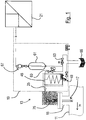
- liquefied gas line 11 is used to convey liquefied gases such as LPG or LNG along a main flow direction H and may for example be part of a liquefaction plant.
- a sampling device 13 In order to analyze the fluids flowing in the liquefied gas line 11, a sampling device 13 according to the invention is provided.
- the sampling device 13 comprises a sample tip 17 mounted on the liquid gas line 11 by means of a connection device 15, via which a sample of the fluids flowing through the liquid gas line 11 is led out of the liquid gas line 11, and an evaporator unit 19 for at least partial evaporation of the removed fluids.
- the evaporator unit 19 is arranged outside the liquefied gas line 11 in the immediate vicinity of the connection device 15. After passing through the evaporator unit 19, the sample fluids are fed to a gas analyzer 21 which comprises at least one gas concentration sensor (not shown individually).
- sample line 25 which is divided into a plurality of differently shaped sections, as described in more detail below. Overall, the sample line 25 may have a length of several meters.
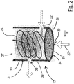
- Fig. 2 1 shows a removal section 27 of the sample line 25, which is located in the area of the sample tip 17 and extends from an upstream open end 29 of the sample line 25.
- the removal portion 27 has a helical course and is covered by a protective tube 30.
- the protective tube 30 has a jacket surface 31, in which an inflow opening 32 and an outflow opening 33 located opposite it are formed.
- On an end face 34 of the protective tube 30 also has a removal opening 35 is formed.
- the open end 29 of the sample line 15 is led out of the protective tube 30 through the removal opening 35 and projects transversely to the main flow direction H into the liquid gas line 11 (FIG. Fig. 1 ) into it.
- the removal section 27 has such a small line cross-section that due to the capillary effect, an entry of fluid into the sample line 15 takes place.
- the entry takes place transversely to the main flow direction H, as shown by the arrow 37.
- the inflow port 32 and the outflow port 33 cause the takeout section 27 of the sample line 25 to be kept cool during operation of the associated plant of cool process fluids, e.g. LPG or LNG flows around, as indicated by the arrows 38 and 39.
- the pressure of the sample fluids decreases, thereby facilitating subsequent evaporation.
- a desired predetermined pressure reduction can be achieved.
- a first evaporation section 40 of the sample line 25 assigned to the evaporator unit 19, which is guided around a heatable body 45 in a downward spiral.
- a second evaporation section 47 is arranged downstream of the first evaporation section 40 and guided around the heatable body 45 along an upward spiral.
- a separation device 49 for separating residual liquid from the sample line 25 is arranged.
- the separation device 49 comprises a coalescing filter (not shown) and a needle valve 50.
- the heatable body 45 is preferably an aluminum block having a cylindrical shape and provided with a central recess 51.
- an electric heating cartridge 53 is used in the central recess 51.
- an electric heating sleeve enclosing the first evaporation section 40 and the second evaporation section 47 may be provided, which in FIG Fig. 3 but not shown.
- Both the first evaporation section 40 and the second evaporation section 47 have a line cross section which is opposite to the line cross section of the removal section 27 (FIG. Fig. 2 ) is enlarged.
- the first evaporation section 40 and the second evaporation section 47 may have a line cross section of 6.35 mm.
- the removal portion 27 may have a wire cross section of about 1.5 mm.
- the first evaporation section 40 and the second evaporation section 47 are made of stainless steel tubes.
- the wire mesh 55 is made preferably made of steel wire and extends the course of the downward screw through the entire first evaporation section 40 therethrough.
- the fluid in the sample line 25 via an in Fig. 1 shown first valve 60 to an accumulator 61 and then fed to the gas analyzer 21.
- a second valve 63 arranged downstream of the first valve 60 serves to separate, if necessary, part of the sample fluid and to supply it to a drain 65. By means of the second valve 63, a flow adjustment can be made. In the drain 65 and the separation device 49 opens.
- the first evaporation section 40 a rectified transport of the components of the sample already transferred to the gas phase takes place together with the liquid constituents in the course of the downward movement.
- the pressure is gradually reduced.
- an effective partial evaporation of those sample components takes place which have a boiling point below the temperature of the heatable body 45.
- the gaseous sample in the second evaporation section 47 is guided upward around the heatable body 45. Due to the rising sample line 25 in the region of the second evaporation section 47 remaining liquid components, for example, go down due to gravity and can be deposited.
- the sample Prior to analysis, the sample passes through the accumulator 61, which acts as a mixing vessel to compensate for local concentration changes. For flow and evaporation adjustment, a portion of the gaseous sample by means of second valve 63 separated. The gaseous residual sample is pressure-reduced by means of a pressure regulator 67. Subsequently, the gaseous residual sample is fed to the gas analyzer 21. Isolation of the pipes located after the removal area is preferred.
- connection device 15 can be seen to comprise a flange 77, a ball valve 75 and a graphite ring connection 80.
- the graphite ring connection 80 is released slowly, whereupon the sample tip 17 is slowly pushed out of the liquid gas line 11 by the process pressure ( Fig. 6 ).
- the process pressure Fig. 6
- the ball valve 75 Once the sample tip 17 as in Fig. 7 has passed the ball valve 75, this can be closed and the probe tip 17 are completely pulled out.
- the re-introduction of the probe tip 17 in the liquefied gas line 11 should then take place at a process pressure of less than 5 bar.
- the graphite ferrule 80 is replaced after each use.
- Fig. 5 is a protective tube 30 in the inserted state enveloping guide 85 recognizable, which ensures in particular during insertion for mechanical safety.
- a sampling device 13 allows in the region of the sample tip 17 a pressure reduction without pre-evaporation and in the evaporator unit 19 a rapid, spatially limited and effective transmission of thermal energy to the sample taken to this for analysis prepare. This makes it possible to carry out continuous analyzes of liquefied gas lines of different types and to keep the proportion of unwanted fractionations low.
Landscapes
- Life Sciences & Earth Sciences (AREA)
- Hydrology & Water Resources (AREA)
- Physics & Mathematics (AREA)
- Health & Medical Sciences (AREA)
- Chemical & Material Sciences (AREA)
- Analytical Chemistry (AREA)
- Biochemistry (AREA)
- General Health & Medical Sciences (AREA)
- General Physics & Mathematics (AREA)
- Immunology (AREA)
- Pathology (AREA)
- Sampling And Sample Adjustment (AREA)
Abstract
Description
- Die vorliegende Erfindung betrifft eine Vorrichtung zur kontinuierlichen Entnahme und Aufbereitung einer Fluidprobe aus einer flüssiggasführenden Prozessleitung mit einer Probenleitung, die ein in die Flüssiggasleitung einführbares offenes Leitungsende aufweist.
- Solche Vorrichtungen werden beispielsweise für die Analyse von Kohlenwasserstoffgemischen benötigt, die durch Prozessleitungen von Verflüssigungsanlagen und dergleichen gefördert werden. Eine kontinuierliche Analyse von Kohlenwasserstoffgemischen ist insbesondere auf dem Gebiet der Handhabung von Flüssiggasen, welche beispielsweise als Liquefied Petroleum Gas (LPG) oder verflüssigtes Erdgas (Liquefied Natural Gas, LNG) vorkommen, erforderlich.
- Nach der Entnahme aus der Prozessleitung muss die flüssige Probe kontinuierlich verdampft werden, damit eine Konzentrationsbestimmung der Bestandteile mittels eines Gasanalysators erfolgen kann. Hierbei besteht das Problem, dass kurzkettige, leichter siedende Komponenten der Probe zuerst in die Gasphase übergehen, wohingegen die längerkettigen, schwerer siedenden Komponenten länger in der flüssigen Phase verbleiben. Dieses Phänomen wird als "Fraktionierung" bezeichnet. Fraktionierung tritt verstärkt auf, wenn die Siedepunkte der einzelnen Komponenten des Flüssigkeitsgemisches weit auseinander liegen. Aufgrund der Fraktionierung kommt es in der Praxis zu schwankenden Ergebnissen am Analysator. Eine zuverlässige und reproduzierbare Analyse ist häufig nicht gewährleistet.
- Um die Fraktionierungsanteile möglichst gering zu halten, ist eine effektive Energieübertragung in einem räumlich begrenzten Bereich innerhalb einer möglichst kurzen Zeit und unter gleichzeitiger Druckreduzierung wünschenswert. Aus Gründen des Explosionsschutzes und eventueller Wärmeleitungseffekte kann die der Probe zugeführte thermische Energie nicht beliebig groß gewählt werden, was zu einer Limitierung der möglichen Heizleistung führt.
- Bei Vorrichtungen der genannten Art können beheizte Druckregler zum Verdampfen der Probe eingesetzt werden. Solche Vorrichtungen weisen jedoch hohe Fraktionierungsanteile auf, die für viele Anwendungen nicht akzeptabel sind. Außerdem besteht bei der Verwendung von beheizten Druckminderern ohne Probenahmesonde, wie sie üblicherweise an flüssiggasführenden Prozessleitungen eingesetzt werden, das Problem der großen zeitlichen Verzögerung zwischen tatsächlicher Probenahme aus dem Prozessstrom und der Analyse im Prozessanalysator.
- Es besteht daher das Bedürfnis, bei der Entnahme und Aufbereitung von Proben aus Flüssiggasleitungen den Fraktionierungsanteil zu verringern und die zeitliche Verzögerung möglichst klein zu halten.
- Die Lösung der Aufgabe erfolgt durch eine Vorrichtung mit den Merkmalen des Anspruchs 1.
- Eine erfindungsgemäße Vorrichtung umfasst eine außerhalb der Flüssiggasleitung anzuordnende Verdampfer-Einheit zum wenigstens teilweisen Verdampfen von durch die Probenleitung strömenden Fluiden, wobei die Verdampfer-Einheit wenigstens einen beheizbaren Körper umfasst. Erfindungsgemäß ist vorgesehen, dass ein erster Verdampfungsabschnitt der Probenleitung in einer Abwärtsschraube verläuft und in einem wärmeleitenden Kontakt mit dem beheizbaren Körper steht. Weiterhin sieht die Erfindung vor, dass ein stromabwärts des ersten Verdampfungsabschnitts befindlicher zweiter Verdampfungsabschnitt der Probenleitung in einer Aufwärtsschraube verläuft und ebenfalls in einem wärmeleitenden Kontakt mit dem beheizbaren Körper steht.
- Die schraubenförmige Leitungsführung sorgt in Verbindung mit dem wärmeleitenden Kontakt zum beheizbaren Körper für eine besonders effektive und räumlich definierte Übertragung thermischer Energie auf das strömende Probenmedium sowie für eine gleichzeitige Reduzierung des Druckes. Dadurch kann der Fraktionierungsanteil auf einen besonders geringen Restwert begrenzt werden. Die Erfindung ermöglicht somit eine zuverlässige kontinuierliche Analyse von Stoffproben, die aus Flüssiggasleitungen entnommen wurden.
- Nach der Verdampfer-Einheit kann die Probenleitung in einen Anschluss für einen Gasanalysator münden oder direkt mit einem Gasanalysator verbunden sein. Um lokale Konzentrationsänderungen zu kompensieren, kann stromabwärts des zweiten Verdampfungsabschnitts wenigstens ein Mischbehälter, insbesondere ein Akkumulator, in die Probenleitung integriert sein.
- Um eine gleichmäßige Wärmeverteilung in der Rohrleitung sicherzustellen, kann/können der erste Verdampfungsabschnitt und/oder der zweite Verdampfungsabschnitt an dem beheizbaren Körper anliegen, vorzugsweise entlang der gesamten Abwärtsschraube bzw. entlang der gesamten Aufwärtsschraube. Bei dem beheizbaren Körper kann es sich insbesondere um einen elektrisch beheizbaren Körper handeln.
- Vorzugsweise ist in dem ersten Verdampfungsabschnitt der Probenleitung ein Drahtgeflecht angeordnet. Das Drahtgeflecht begünstigt eine Durchmischung der flüssigen und der gasförmigen Bestandteile in der Probenleitung und sorgt so in ähnlicher Weise wie bei einer Mehrfachdestillation für eine effektivere Verdampfung der flüssigen Bestandteile. Außerdem fördert die durch das Drahtgeflecht bewirkte Reduzierung des Leitungsquerschnitts und gegebenenfalls die erzeugte Turbulenz den Druckabfall in der Probenleitung, was einer effektiven Verdampfung ebenfalls entgegenkommt. Zusätzlich dient das Drahtgeflecht zur Effektivitätsmaximierung des Wärmeübertrages.
- Das Drahtgeflecht kann insbesondere aus Stahldraht gefertigt sein. Da sich das Drahtgeflecht in unmittelbarer Nähe zum beheizbaren Körper befindet, wird es durch diesen aufgeheizt und steigert so die Übertragung thermischer Energie auf das Probenmedium. Bei Bedarf könnte das Drahtgeflecht auch direkt beheizt werden, beispielsweise auf elektrischem Wege.
- Eine spezielle Ausgestaltung der Erfindung sieht vor, dass das Drahtgeflecht bezogen auf den Leitungsquerschnitt des ersten Verdampfungsabschnitts zentral angeordnet ist und/oder sich zumindest im Wesentlichen entlang der gesamten Abwärtsschraube erstreckt. Es ist also bevorzugt, dass das Drahtgeflecht länglich ist und koaxial zur Probenleitung verläuft, sodass die Turbulenzerzeugung gleichmäßig ist.
- Der beheizbare Körper kann eine zylindrische Form aufweisen, damit sich die Abwärtsschraube und die Aufwärtsschraube jeweils gut an den beheizbaren Körper anlegen können. Bevorzugt fällt hierbei eine Zylinderachse des beheizbaren Körpers mit einer Schraubenachse der Abwärtsschraube und/oder mit einer Schraubenachse der Aufwärtsschraube zusammen.
- Bevorzugt ist vorgesehen, dass der erste Verdampfungsabschnitt und/oder der zweite Verdampfungsabschnitt um den beheizbaren Körper herumgeführt ist/sind. Der beheizbare Körper kann somit in allen radialen Richtungen Energie auf die Probenleitung und das darin strömende Fluid abgeben.
- Eine besonders einfach herstellbare Ausführungsform der Erfindung sieht vor, dass der beheizbare Körper einen Metallblock, insbesondere einen Aluminiumblock, umfasst.
- Der Metallblock kann eine Aussparung aufweisen, in die ein elektrisches Heizelement wie zum Beispiel eine Heizpatrone einsetzbar ist. Dies ermöglicht eine besonders einfache Konstruktion.
- Die Verdampfer-Einheit kann außerdem eine Heizmanschette umfassen, die den ersten Verdampfungsabschnitt und den zweiten Verdampfungsabschnitt wenigstens teilweise umschließt. Dies ermöglicht eine Beheizung der schraubenförmigen Verdampfungsabschnitte von außen. Bei bestimmten Anwendungen könnte es sogar ausreichend sein, ausschließlich eine Heizung der Verdampfungsabschnitte mittels einer Heizmanschette vorzusehen. Bevorzugt ist es aber vorgesehen, dass zumindest ein Metallblock mit um diesen herumgeführten Verdampfungsabschnitten und besonders bevorzugt sowohl ein Metallblock mit um diesen herumgeführten Verdampfungsabschnitten als auch eine Heizmanschette bereitgestellt sind. Es versteht sich, dass eine Heizung der Verdampfungsabschnitte von außen und von innen besonders effektiv ist.
- Eine weitere Ausführungsform der Erfindung sieht vor, dass zwischen dem ersten Verdampfungsabschnitt und dem zweiten Verdampfungsabschnitt eine Abscheidevorrichtung zum Abscheiden von Restflüssigkeit aus der Probenleitung angeordnet ist. Die unvermeidliche Restflüssigkeit sammelt sich in der durch den Übergang von der Abwärtsspirale zur Aufwärtsspirale gebildeten Senke und kann an dieser Stelle effektiv aus dem Probenleitungssystem entfernt werden.
- Die Abscheidevorrichtung kann einen Koaleszenzfilter und bevorzugt ein Nadelventil umfassen. Der Koaleszenzfilter kann ein polares, netzartiges Material umfassen, welches Aerosole und flüssige Bestandteile von der Gasphase abtrennt. Ein Nadelventil ermöglicht ein partielles Ableiten von gasförmigem Probenmaterial, um eine unerwünschte Überladung des Koaleszenzfilters zu vermeiden.
- Die Abscheidevorrichtung kann je nach Bedarf, dem zu untersuchenden Fluid oder den äußeren Gegebenheiten und Notwendigkeiten zu- oder abgeschaltet werden.
- Eine erfindungsgemäße Vorrichtung kann eine an der Flüssiggasleitung anbringbare Anschlusseinrichtung aufweisen, über welche das offene Leitungsende in die Flüssiggasleitung einführbar und aus der Flüssiggasleitung entfernbar ist. Die Entnahmevorrichtung kann aufgrund der Anschlusseinrichtung leicht abgebaut oder ausgewechselt werden.
- Um ein Verschließen der Flüssiggasleitung nach einer Entnahme der Vorrichtung zu ermöglichen, kann die Anschlusseinrichtung eine bedienbare Absperrvorrichtung, insbesondere einen Kugelhahn, umfassen.
- Alternativ oder zusätzlich kann die Anschlusseinrichtung eine Verschraubung, insbesondere eine Graphitringverschraubung, umfassen.
- Eine weitere Ausführungsform der Erfindung sieht vor, dass das offene Leitungsende an einem Entnahmeabschnitt der Probenleitung ausgebildet ist, der einen gegenüber dem ersten Verdampfungsabschnitt verringerten Leitungsquerschnitt aufweist. Es ist also bevorzugt, dass der Leitungsquerschnitt der Probenleitung vor oder bei dem Eintritt in die Verdampfer-Einheit vergrößert wird. Dadurch wird ein ausreichendes Volumen für das in die Gasphase übergehende Probenmaterial zur Verfügung gestellt. Der vergleichsweise geringe Leitungsquerschnitt des Entnahmeabschnitts wird in seinen Dimensionen hingegen so gewählt, dass er für einen druckreduzierenden Kapillareffekt sorgt, und wird daher auch als Kapillare bezeichnet. Bei dieser weiteren Ausführungsform kann wirkungsvoll erreicht werden, dass die eigentliche Verdampfung erst während oder nach einer Druckreduktion erfolgt. Vorzugsweise ist vorgesehen, dass der Entnahmeabschnitt einen Leitungsquerschnitt von höchstens 1,5 mm aufweist und/oder der erste Verdampfungsabschnitt einen Leitungsquerschnitt von wenigstens 3 mm aufweist. Die Kapillare ist jedoch gegebenenfalls an die speziellen Anforderungen individuell angepasst.
- Eine weitere Ausführungsform der Erfindung sieht vor, dass der Entnahmeabschnitt zumindest bereichsweise einen schraubenförmigen Verlauf aufweist und somit die Länge des Entnahmeabschnittes innerhalb gewisser Grenzen unabhängig vom Bauraum individuell gewählt werden kann. Somit kann ein beträchtlicher Teil der erforderlichen Druckreduzierung innerhalb der Prozessleitung erfolgen, wo es aufgrund des den Entnahmeabschnitt umströmenden Flüssiggases zu einer Temperaturstabilisierung kommt. Unerwünschte Vorverdampfungen, welche die Fraktionierung erhöhen, können so wirkungsvoll vermieden bzw. verringert werden.
- Der Entnahmeabschnitt kann in einem Gehäuse angeordnet sein, das wenigstens eine freie Einströmöffnung, wenigstens eine freie Ausströmöffnung und eine dem offenen Leitungsende zugeordnete Entnahmeöffnung aufweist. Dies dient einerseits der Stabilisierung innerhalb der Prozessleitung und andererseits einer Vereinfachung der Entnahme aus der Prozessleitung. Die freie Einströmöffnung und die freie Ausströmöffnung gewährleisten eine Umströmung des Entnahmeabschnitts durch das Prozessfluid und somit eine erwünschte Kühlung des Probenfluids, während durch die Entnahmeöffnung das Probenmaterial abgeführt wird. Das Gehäuse kann insbesondere rohrförmig sein, also zum Beispiel als Schutzrohr oder Stützrohr ausgeführt sein.
- Bevorzugt ist die Entnahmeöffnung so ausgestaltet, dass sie im montierten Zustand der Vorrichtung quer zu der freien Einströmöffnung, quer zu der freien Ausströmöffnung und/oder quer zu einer Hauptströmungsrichtung der Flüssiggasleitung ausgerichtet ist. Durch Wahl der Durchflussgeschwindigkeit und des Rohrleitungsdurchmessers kann ein erwünschter Druckverlust im Entnahmeabschnitt der Probenleitung erzeugt werden. Auf diese Weise kann die entnommene Probe in einen moderaten Druckbereich überführt werden. Außerdem kann erreicht werden, dass der Entnahmeabschnitt von gegebenenfalls kühlen Prozessfluiden in der flüssiggasführenden Prozessleitung umströmt wird, wodurch ebenfalls eine zu frühzeitige Verdampfung wirkungsvoll verringert bzw. vermieden werden kann.
- Wie beschrieben entfalten die vorstehend angegebenen, auf den Entnahmeabschnitt bezogenen Merkmale auch vorteilhafte technische Wirkungen, die der Lösung der Aufgabe dienen aber unabhängig von der Ausgestaltung der Verdampfer-Einheit sind, so dass für diese Merkmale auch separat Schutz beansprucht wird (Anspruch 12 und entsprechende Unteransprüche).
- Weiterbildungen der Erfindung sind auch den abhängigen Ansprüchen, der Beschreibung sowie den beigefügten Zeichnungen zu entnehmen.
- Die Erfindung wird nachfolgend beispielhaft unter Bezugnahme auf die Zeichnungen beschrieben.
- Fig. 1
- ist eine schematische Darstellung einer erfindungsgemäßen Vorrichtung zur Entnahme und Aufbereitung einer Fluidprobe aus einer Flüssiggasleitung.
- Fig. 2
- zeigt einen Entnahmeabschnitt einer Probenleitung der in
Fig. 1 gezeigten Vorrichtung. - Fig. 3
- zeigt eine Verdampfer-Einheit der in
Fig. 1 dargestellten Vorrichtung. - Fig. 4
- zeigt ein in einer Probenleitung der Vorrichtung gemäß
Fig. 1 angeordnetes Drahtgeflecht. - Fig. 5
- ist eine vergrößerte Teildarstellung der in
Fig. 1 gezeigten Vorrichtung, welche eine an der Flüssiggasleitung angebrachte Anschlusseinrichtung genauer zeigt. - Fig. 6
- zeigt einen Abschnitt der Anschlusseinrichtung gemäß
Fig. 5 mit einem in die Flüssiggasleitung eingeführten Ende der Probenleitung. - Fig. 7
- zeigt die Anordnung gemäß
Fig. 6 während des Entfernens des Endes der Probenleitung aus der Flüssiggasleitung. - Die in
Fig. 1 nur teilweise dargestellte Flüssiggasleitung 11 dient zur Förderung von verflüssigten Gasen wie zum Beispiel LPG oder LNG entlang einer Hauptströmungsrichtung H und kann beispielsweise Bestandteil einer Verflüssigungsanlage sein. Um die in der Flüssiggasleitung 11 strömenden Fluide zu analysieren, ist eine erfindungsgemäße Probeentnahmevorrichtung 13 vorgesehen. Die Probenentnahmevorrichtung 13 umfasst eine mittels einer Anschlusseinrichtung 15 an der Flüssiggasleitung 11 montierte Probenspitze 17, über welche eine Probe der durch die Flüssiggasleitung 11 strömenden Fluide aus der Flüssiggasleitung 11 herausgeführt wird, sowie eine Verdampfer-Einheit 19 zum wenigstens teilweisen Verdampfen der entnommenen Fluide. Die Verdampfer-Einheit 19 ist außerhalb der Flüssiggasleitung 11 in unmittelbarer Nähe zur Anschlusseinrichtung 15 angeordnet. Nach Passieren der Verdampfer-Einheit 19 werden die Probenfluide einem Gasanalysator 21 zugeführt, der wenigstens einen nicht einzeln dargestellten Gaskonzentrationssensor umfasst. - Das Entnehmen und Aufbereiten der Probenfluide erfolgt in einer Probenleitung 25, die in mehrere unterschiedlich gestaltete Abschnitte unterteilt ist, wie nachfolgend näher ausgeführt ist. Insgesamt kann die Probenleitung 25 eine Länge von mehreren Metern aufweisen.
-
Fig. 2 zeigt einen Entnahmeabschnitt 27 der Probenleitung 25, der sich im Bereich der Probenspitze 17 befindet und sich ausgehend von einem stromaufwärtigen offenen Ende 29 der Probenleitung 25 erstreckt. Wie dargestellt weist der Entnahmeabschnitt 27 einen schraubenförmigen Verlauf auf und ist von einem Schutzrohr 30 umhüllt. Das Schutzrohr 30 weist eine Mantelfläche 31 auf, in welcher eine Einströmöffnung 32 sowie eine dieser gegenüberliegende Ausströmöffnung 33 ausgebildet ist. An einer Stirnfläche 34 des Schutzrohrs 30 ist außerdem eine Entnahmeöffnung 35 ausgebildet. Das offene Ende 29 der Probenleitung 15 ist durch die Entnahmeöffnung 35 aus dem Schutzrohr 30 herausgeführt und ragt quer zu der Hauptströmungsrichtung H in die Flüssiggasleitung 11 (Fig. 1 ) hinein. - Der Entnahmeabschnitt 27 weist einen derart geringen Leitungsquerschnitt auf, dass aufgrund des Kapillareffekts ein Eintreten von Fluid in die Probenleitung 15 erfolgt. Das Eintreten erfolgt quer zur Hauptströmungsrichtung H, wie durch den Pfeil 37 dargestellt ist. Die Einströmöffnung 32 und die Ausströmöffnung 33 bewirken, dass der Entnahmeabschnitt 27 der Probenleitung 25 während des Betriebs der zugehörigen Anlage von kühlen Prozessfluiden wie z.B. LPG oder LNG umströmt wird, wie durch die Pfeile 38 und 39 angegeben ist.
- Beim Durchströmen des Entnahmeabschnitts 27 verringert sich der Druck der Probenfluide, wodurch eine nachfolgende Verdampfung vereinfacht wird. Durch Anpassung der Leitungslänge, des Leitungsquerschnitts sowie der Oberflächenbeschaffenheit der Innenwand des Entnahmeabschnitts 27 kann eine gewünschte vorgegebene Druckverringerung erzielt werden.
- Wie in
Fig. 1 in Verbindung mitFig. 3 erkennbar gezeigt, befindet sich stromabwärts des Entnahmeabschnitts 27 ein der Verdampfer-Einheit 19 zugeordneter erster Verdampfungsabschnitt 40 der Probenleitung 25, der in einer Abwärtsspirale um einen beheizbaren Körper 45 herumgeführt ist. Ein zweiter Verdampfungsabschnitt 47 ist stromabwärts des ersten Verdampfungsabschnitts 40 angeordnet und entlang einer Aufwärtsspirale um den beheizbaren Körper 45 herumgeführt. Zwischen dem ersten Verdampfungsabschnitt 40 und dem zweiten Verdampfungsabschnitt 47 ist eine Abscheidevorrichtung 49 zum Abscheiden von Restflüssigkeit aus der Probenleitung 25 angeordnet. Die Abscheidevorrichtung 49 umfasst einen Koaleszenzfilter (nicht dargestellt) und ein Nadelventil 50. - Bei dem beheizbaren Körper 45 handelt es sich vorzugsweise um einen Aluminiumblock, der eine zylindrische Form aufweist und mit einer zentralen Aussparung 51 versehen ist. In die zentrale Aussparung 51 ist eine elektrische Heizpatrone 53 eingesetzt. Zusätzlich kann eine den ersten Verdampfungsabschnitt 40 und den zweiten Verdampfungsabschnitt 47 umschließende elektrische Heizmanschette vorgesehen sein, welche in
Fig. 3 jedoch nicht dargestellt ist. - Sowohl der erste Verdampfungsabschnitt 40 als auch der zweite Verdampfungsabschnitt 47 weisen einen Leitungsquerschnitt auf, der gegenüber dem Leitungsquerschnitt des Entnahmeabschnitts 27 (
Fig. 2 ) vergrößert ist. Beispielsweise können der erste Verdampfungsabschnitt 40 und der zweite Verdampfungsabschnitt 47 einen Leitungsquerschnitt von 6,35 mm aufweisen. Der Entnahmeabschnitt 27 kann einen Leitungsquerschnitt von etwa 1,5 mm aufweisen. Vorzugsweise sind der erste Verdampfungsabschnitt 40 und der zweite Verdampfungsabschnitt 47 als Edelstahlrohre ausgeführt. - In dem ersten Verdampfungsabschnitt 40 der Probenleitung 25 ist ein Drahtgeflecht 55 angeordnet, wie in
Fig. 4 dargestellt ist. Das Drahtgeflecht 55 besteht vorzugsweise aus Stahldraht und erstreckt sich dem Verlauf der Abwärtsschraube folgend durch den gesamten ersten Verdampfungsabschnitt 40 hindurch. - Nach Passieren des zweiten Verdampfungsabschnitts 47 wird das Fluid in der Probenleitung 25 über ein in
Fig. 1 gezeigtes erstes Ventil 60 einem Akkumulator 61 und anschließend dem Gasanalysator 21 zugeführt. Ein stromabwärts des ersten Ventils 60 angeordnetes zweites Ventil 63 dient dazu, bei Bedarf einen Teil des Probenfluids abzutrennen und einem Ablass 65 zuzuführen. Mittels des zweiten Ventils 63 kann eine Durchflussjustage vorgenommen werden. In den Ablass 65 mündet auch die Abscheidevorrichtung 49. - Im ersten Verdampfungsabschnitt 40 erfolgt ein gleichgerichteter Transport der bereits in die Gasphase übergegangenen Bestandteile der Probe zusammen mit den flüssigen Bestandteilen im Verlauf der Abwärtsbewegung. Dabei wird der Druck allmählich abgebaut. Durch das Drahtgeflecht 55 (
Fig. 4 ) findet eine Durchmischung der gasförmigen und flüssigen Bestandteile statt, woraus eine besonders effektive Verdampfung der sich noch in der flüssigen Phase befindlichen Bestandteile resultiert. Bis zum Ende des ersten Verdampfungsabschnitts 40 findet eine effektive Partialverdampfung derjenigen Probenbestandteile statt, welche einen Siedepunkt unterhalb der Temperatur des beheizbaren Körpers 45 aufweisen. Nach Abtrennung der verbliebenen flüssigen Probenbestandteile in der Abscheidevorrichtung 49 wird die gasförmige Probe im zweiten Verdampfungsabschnitt 47 aufwärts um den beheizbaren Körper 45 herumgeführt. Aufgrund der ansteigenden Probenleitung 25 im Bereich des zweiten Verdampfungsabschnitts 47 gelangen verbliebene flüssige Bestandteile zum Beispiel schwerkraftbedingt nach unten und können abgeschieden werden. - Vor der Analyse passiert die Probe den Akkumulator 61, welcher als Mischbehälter fungiert, um lokale Konzentrationsänderungen zu kompensieren. Zur Durchfluss- und Verdampfungsjustage wird ein Teil der gasförmigen Probe mittels des zweiten Ventils 63 abgetrennt. Die gasförmige Restprobe wird mittels eines Druckreglers 67 druckreduziert. Anschließend wird die gasförmige Restprobe dem Gasanalysator 21 zugeführt. Eine Isolierung der nach dem Entnahmebereich befindlichen Leitungen ist bevorzugt.
- Ein bedarfsweises Entnehmen der Probenspitze 17 aus der Flüssiggasleitung 11 wird nachfolgend unter Bezugnahme auf die
Fig. 5 bis 7 beschrieben. Wie inFig. 5 erkennbar umfasst die Anschlusseinrichtung 15 einen Flansch 77, einen Kugelhahn 75 sowie eine Graphitringverschraubung 80. Zum Entnehmen der Probenspitze 17 wird die Graphitringverschraubung 80 langsam gelöst, woraufhin die Probenspitze 17 durch den Prozessdruck langsam aus der Flüssiggasleitung 11 herausgedrückt wird (Fig. 6 ). Sobald die Probenspitze 17 wie inFig. 7 gezeigt den Kugelhahn 75 passiert hat, kann dieser geschlossen und die Probenspitze 17 vollständig herausgezogen werden. Die erneute Einführung der Probenspitze 17 in die Flüssiggasleitung 11 sollte dann bei einem Prozessdruck von weniger als 5 bar erfolgen. Vorzugsweise wird die Graphitringverschraubung 80 nach jeder Benutzung ersetzt. - In
Fig. 5 ist eine das Schutzrohr 30 im eingeführten Zustand umhüllende Führung 85 erkennbar, die insbesondere auch beim Einführen für mechanische Sicherheit sorgt. - Vorteilhafterweise wird zwischen dem Kugelhahn 75 und der Verdampfer-Einheit 19 ein die (im Schutzrohr 30 angeordnete) Probenleitung zumindest bereichsweise umschließendes Teflonrohr zur thermischen Isolation vorgesehen.
- Eine erfindungsgemäße Probenentnahmevorrichtung 13 ermöglicht im Bereich der Probenspitze 17 eine Druckreduzierung ohne Vorverdampfung und im Bereich der Verdampfer-Einheit 19 eine schnelle, räumlich begrenzte und effektive Übertragung thermischer Energie auf die entnommene Probe, um diese für eine Analyse aufzubereiten. Dadurch wird es möglich, an Flüssiggasleitungen unterschiedlicher Art kontinuierliche Analysen vorzunehmen und hierbei den Anteil unerwünschter Fraktionierungen gering zu halten.
-
- 11
- Flüssiggasleitung
- 13
- Probenentnahmevorrichtung
- 15
- Anschlusseinrichtung
- 17
- Probenspitze
- 19
- Verdampfer-Einheit
- 21
- Gasanalysator
- 25
- Probenleitung
- 27
- Entnahmeabschnitt
- 29
- offenes Ende
- 30
- Schutzrohr
- 31
- Mantelfläche
- 32
- Einströmöffnung
- 33
- Ausströmöffnung
- 34
- Stirnfläche
- 35
- Entnahmeöffnung
- 37
- Absaugrichtung
- 38
- Einströmrichtung
- 39
- Ausströmrichtung
- 40
- erster Verdampfungsabschnitt
- 45
- beheizbarer Körper
- 47
- zweiter Verdampfungsabschnitt
- 49
- Abscheidevorrichtung
- 50
- Nadelventil
- 51
- Aussparung
- 53
- Heizpatrone
- 55
- Drahtgeflecht
- 60
- erstes Ventil
- 61
- Akkumulator
- 63
- zweites Ventil
- 65
- Ablass
- 67
- Druckregler
- 75
- Kugelhahn
- 77
- Flansch
- 80
- Graphtringverschraubung
- 85
- Führung
- H
- Hauptströmungsrichtung
Claims (15)
- Vorrichtung (13) zur kontinuierlichen Entnahme und Aufbereitung einer Fluidprobe aus einer flüssiggasführenden Prozessleitung (11) mit einer Probenleitung (25), die ein in die Flüssiggasleitung (11) einführbares offenes Leitungsende (29) aufweist und
einer außerhalb der Flüssiggasleitung (11) anzuordnenden Verdampfer-Einheit (19) zum wenigstens teilweisen Verdampfen von durch die Probenleitung (25) strömenden Fluiden,
wobei die Verdampfer-Einheit (19) wenigstens einen beheizbaren Körper (45) umfasst,
wobei ein erster Verdampfungsabschnitt (40) der Probenleitung (25) in einer Abwärtsschraube verläuft und in einem wärmeleitenden Kontakt mit dem beheizbaren Körper (45) steht,
und wobei ein stromabwärts des ersten Verdampfungsabschnitts (40) befindlicher zweiter Verdampfungsabschnitt (47) der Probenleitung (25) in einer Aufwärtsschraube verläuft und ebenfalls in einem wärmeleitenden Kontakt mit dem beheizbaren Körper (45) steht. - Vorrichtung nach Anspruch 1,
dadurch gekennzeichnet, dass
zumindest in dem ersten Verdampfungsabschnitt (40) der Probenleitung (25) ein Drahtgeflecht (55) angeordnet ist. - Vorrichtung nach einem der vorstehenden Ansprüche,
dadurch gekennzeichnet, dass
der erste Verdampfungsabschnitt (40) und/oder der zweite Verdampfungsabschnitt (47) um den beheizbaren Körper (45) herumgeführt ist/sind. - Vorrichtung nach einem der vorstehenden Ansprüche,
dadurch gekennzeichnet, dass
der beheizbare Körper (45) einen Metallblock, insbesondere einen Aluminiumblock, umfasst. - Vorrichtung nach Anspruch 4,
dadurch gekennzeichnet, dass
der Metallblock eine Aussparung (51) aufweist, in die ein elektrisches Heizelement (53) wie z. B. eine Heizpatrone einsetzbar ist. - Vorrichtung nach einem der vorstehenden Ansprüche,
dadurch gekennzeichnet, dass
die Verdampfer-Einheit (19) eine Heizmanschette umfasst, die den ersten Verdampfungsabschnitt (40) und den zweiten Verdampfungsabschnitt (47) wenigstens teilweise umschließt. - Vorrichtung nach einem der vorstehenden Ansprüche,
dadurch gekennzeichnet, dass
zwischen dem ersten Verdampfungsabschnitt (40) und dem zweiten Verdampfungsabschnitt (47) eine Abscheidevorrichtung (49) zum Abscheiden von Restflüssigkeit aus der Probenleitung (25) angeordnet ist. - Vorrichtung nach Anspruch 7,
dadurch gekennzeichnet, dass
dass die Abscheidevorrichtung (49) einen Koaleszenzfilter und bevorzugt ein Nadelventil (50) umfasst. - Vorrichtung nach einem der vorstehenden Ansprüche,
dadurch gekennzeichnet, dass
eine an der Flüssiggasleitung (11) anbringbare Anschlusseinrichtung (15) vorgesehen ist, über welche das offene Leitungsende (29) in die Flüssiggasleitung (11) einführbar und aus der Flüssiggasleitung (11) entfernbar ist. - Vorrichtung nach Anspruch 9,
dadurch gekennzeichnet, dass
die Anschlusseinrichtung (15) eine bedienbare Absperrvorrichtung (75), insbesondere einen Kugelhahn, und/oder eine Verschraubung (80), insbesondere eine Graphitringverschraubung, umfasst. - Vorrichtung nach zumindest einem der vorstehenden Ansprüche,
dadurch gekennzeichnet, dass
das offene Leitungsende (29) an einem Entnahmeabschnitt (27) der Probenleitung (25) ausgebildet ist, der einen gegenüber dem ersten Verdampfungsabschnitt (40) verringerten Leitungsquerschnitt aufweist. - Vorrichtung (13) zur kontinuierlichen Entnahme und Aufbereitung einer Fluidprobe aus einer flüssiggasführenden Prozessleitung (11) mit
einer Probenleitung (25), die ein in die Flüssiggasleitung (11) einführbares offenes Leitungsende (29) aufweist und
einer außerhalb der Flüssiggasleitung (11) anzuordnenden Verdampfer-Einheit (19) zum wenigstens teilweisen Verdampfen von durch die Probenleitung (25) strömenden Fluiden,
wobei das offene Leitungsende (29) an einem Entnahmeabschnitt (27) der Probenleitung (25) ausgebildet ist, der einen gegenüber dem nachfolgenden Probenleitungsabschnitt verringerten Leitungsquerschnitt aufweist. - Vorrichtung nach einem der Ansprüche 11 oder 12,
dadurch gekennzeichnet, dass
der Entnahmeabschnitt (27) zumindest bereichsweise einen schraubenförmigen Verlauf aufweist. - Vorrichtung nach einem der Ansprüche 11 bis 13,
dadurch gekennzeichnet, dass
der Entnahmeabschnitt (27) in einem Gehäuse (30) angeordnet ist, das wenigstens eine freie Einströmöffnung (32), wenigstens eine freie Ausströmöffnung (33) und eine dem offenen Leitungsende (29) zugeordnete Entnahmeöffnung (35) aufweist. - Vorrichtung nach Anspruch 14,
dadurch gekennzeichnet, dass
die Entnahmeöffnung (35) im in die flüssiggasführende Prozessleitunug montierten Zustand der Vorrichtung (13) quer zu der freien Einströmöffnung (32), quer zu der freien Ausströmöffnung (33) und/oder quer zu einer Hauptströmungsrichtung (H) der Flüssiggasleitung (11) ausgerichtet ist.
Priority Applications (2)
| Application Number | Priority Date | Filing Date | Title |
|---|---|---|---|
| EP17189748.1A EP3454035B1 (de) | 2017-09-07 | 2017-09-07 | Vorrichtungen zur kontinuierlichen entnahme und aufbereitung einer fluidprobe aus einer flüssiggasführenden prozessleitung |
| PCT/EP2018/072860 WO2019048258A1 (de) | 2017-09-07 | 2018-08-24 | Vorrichtung zur kontinuierlichen entnahme und aufbereitung einer fluidprobe aus einer flüssiggasführenden prozessleitung |
Applications Claiming Priority (1)
| Application Number | Priority Date | Filing Date | Title |
|---|---|---|---|
| EP17189748.1A EP3454035B1 (de) | 2017-09-07 | 2017-09-07 | Vorrichtungen zur kontinuierlichen entnahme und aufbereitung einer fluidprobe aus einer flüssiggasführenden prozessleitung |
Publications (2)
| Publication Number | Publication Date |
|---|---|
| EP3454035A1 true EP3454035A1 (de) | 2019-03-13 |
| EP3454035B1 EP3454035B1 (de) | 2022-01-12 |
Family
ID=59895055
Family Applications (1)
| Application Number | Title | Priority Date | Filing Date |
|---|---|---|---|
| EP17189748.1A Active EP3454035B1 (de) | 2017-09-07 | 2017-09-07 | Vorrichtungen zur kontinuierlichen entnahme und aufbereitung einer fluidprobe aus einer flüssiggasführenden prozessleitung |
Country Status (2)
| Country | Link |
|---|---|
| EP (1) | EP3454035B1 (de) |
| WO (1) | WO2019048258A1 (de) |
Citations (6)
| Publication number | Priority date | Publication date | Assignee | Title |
|---|---|---|---|---|
| US3357256A (en) * | 1965-08-16 | 1967-12-12 | Air Reduction | Sampling line for cryogenic liquid mixtures |
| US5161381A (en) * | 1991-03-20 | 1992-11-10 | Praxair Technology, Inc. | Cryogenic liquid sampling system |
| WO2009114980A1 (zh) * | 2008-03-18 | 2009-09-24 | Xu Lihua | 空调热交换式冷凝器及喷淋蒸发冷却系统 |
| EP2163878A1 (de) * | 2008-09-11 | 2010-03-17 | Linde AG | Verfahren und Vorrichtung zur Probenahme kryogener Flüssigkeiten |
| US20120138268A1 (en) * | 2010-12-06 | 2012-06-07 | Saudi Arabian Oil Company | Combined Cooling of Lube/Seal Oil and Sample Coolers |
| US20140230521A1 (en) * | 2005-02-22 | 2014-08-21 | Mustang Sampling, Llc | Liquid gas vaporization and measurement system and method |
-
2017
- 2017-09-07 EP EP17189748.1A patent/EP3454035B1/de active Active
-
2018
- 2018-08-24 WO PCT/EP2018/072860 patent/WO2019048258A1/de not_active Ceased
Patent Citations (6)
| Publication number | Priority date | Publication date | Assignee | Title |
|---|---|---|---|---|
| US3357256A (en) * | 1965-08-16 | 1967-12-12 | Air Reduction | Sampling line for cryogenic liquid mixtures |
| US5161381A (en) * | 1991-03-20 | 1992-11-10 | Praxair Technology, Inc. | Cryogenic liquid sampling system |
| US20140230521A1 (en) * | 2005-02-22 | 2014-08-21 | Mustang Sampling, Llc | Liquid gas vaporization and measurement system and method |
| WO2009114980A1 (zh) * | 2008-03-18 | 2009-09-24 | Xu Lihua | 空调热交换式冷凝器及喷淋蒸发冷却系统 |
| EP2163878A1 (de) * | 2008-09-11 | 2010-03-17 | Linde AG | Verfahren und Vorrichtung zur Probenahme kryogener Flüssigkeiten |
| US20120138268A1 (en) * | 2010-12-06 | 2012-06-07 | Saudi Arabian Oil Company | Combined Cooling of Lube/Seal Oil and Sample Coolers |
Also Published As
| Publication number | Publication date |
|---|---|
| EP3454035B1 (de) | 2022-01-12 |
| WO2019048258A1 (de) | 2019-03-14 |
Similar Documents
| Publication | Publication Date | Title |
|---|---|---|
| DE69133114T2 (de) | Vorrichtung und Verfahren zur Extraktion mit superkritischen Fluiden | |
| EP0750746B1 (de) | Vorrichtung zur handhabung von flüssigkeiten für analytische zwecke | |
| DE2937278C2 (de) | Verfahren und Vorrichtung zur Einführung von Proben in gaschromatographische Säulen | |
| EP0292612B1 (de) | Gaschromatograph, Verzweigungsstück hierfür und Verfahren zur gaschromatographischen Trennung | |
| DE202006021311U1 (de) | Gassonden | |
| DE1138257B (de) | Vorrichtung zur Probenahme verfluessigter Gase zwecks analytischer Ermittlung ihrer Zusammensetzung | |
| DE2445124A1 (de) | Automatische massenspektrometrieanalysiervorrichtung | |
| DE1245998B (de) | Einrichtung zum Verflüssigen von Gasen wie Helium | |
| DE60307713T2 (de) | Verfahren und kryogene Flüssigkeiten Probenahmeeinrichtung, sowie Luftzerlegungsanlage mit solcher Einrichtung | |
| DE19543473C2 (de) | Vorrichtung und Verfahren zum Entfernen von Ablagerungen bei der Erdöl- und Erdgasförderung | |
| EP3454035B1 (de) | Vorrichtungen zur kontinuierlichen entnahme und aufbereitung einer fluidprobe aus einer flüssiggasführenden prozessleitung | |
| DE19850082B4 (de) | Anordnung einer Rauchgasentnahmesonde | |
| DE2004181A1 (de) | Vorsaeulen-Einlass fuer Chromatographen | |
| DE2239678C3 (de) | Verdampfungsapparat für flüssige Narkotika | |
| DE2444201A1 (de) | Verfahren und vorrichtung zur gasentnahme | |
| US20170122848A1 (en) | In-Line Thermal Isolator for Liquid Sample Conditioning | |
| EP2163878A1 (de) | Verfahren und Vorrichtung zur Probenahme kryogener Flüssigkeiten | |
| DE112019003012T5 (de) | ICP Spektroskopie-Brenner mit abnehmbarem, einteiligem Injektor | |
| DE1598056B2 (de) | Chromatographisches Analysengerät | |
| EP2394158A1 (de) | Vorrichtung und verfahren zum aufbereiten von proben für die gaschromatografie | |
| DE2507261A1 (de) | Narkosemittelverdunster mit einem der verdunsterkammer parallelgeschalteten bypass | |
| DE102009023320B3 (de) | Vorrichtungen und Verfahren zur Zuführung eines verflüssigten Gases in ein Gefäß | |
| WO2015121095A1 (de) | Vorrichtung zum bestimmen des massenflusses eines gases beziehungsweise gasgemisches mit ineinandergeschachtelten rohrförmigen filamentanordnungen | |
| EP1524883A1 (de) | Vorrichtung zum Beheizen von in rohrförmigen Transport-und/oder Förderleitungen transportierten fluiden Medien | |
| EP4251991B1 (de) | Vorrichtung für einen gaschromatographen, insbesondere einen temperaturgradienten-gaschromatographen, sowie gaschromatograph mit einer solchen vorrichtung |
Legal Events
| Date | Code | Title | Description |
|---|---|---|---|
| PUAI | Public reference made under article 153(3) epc to a published international application that has entered the european phase |
Free format text: ORIGINAL CODE: 0009012 |
|
| STAA | Information on the status of an ep patent application or granted ep patent |
Free format text: STATUS: THE APPLICATION HAS BEEN PUBLISHED |
|
| AK | Designated contracting states |
Kind code of ref document: A1 Designated state(s): AL AT BE BG CH CY CZ DE DK EE ES FI FR GB GR HR HU IE IS IT LI LT LU LV MC MK MT NL NO PL PT RO RS SE SI SK SM TR |
|
| AX | Request for extension of the european patent |
Extension state: BA ME |
|
| STAA | Information on the status of an ep patent application or granted ep patent |
Free format text: STATUS: REQUEST FOR EXAMINATION WAS MADE |
|
| 17P | Request for examination filed |
Effective date: 20190910 |
|
| RBV | Designated contracting states (corrected) |
Designated state(s): AL AT BE BG CH CY CZ DE DK EE ES FI FR GB GR HR HU IE IS IT LI LT LU LV MC MK MT NL NO PL PT RO RS SE SI SK SM TR |
|
| RAP1 | Party data changed (applicant data changed or rights of an application transferred) |
Owner name: LINDE AKTIENGESELLSCHAFT Owner name: SICK AG |
|
| RAP1 | Party data changed (applicant data changed or rights of an application transferred) |
Owner name: SICK AG |
|
| GRAP | Despatch of communication of intention to grant a patent |
Free format text: ORIGINAL CODE: EPIDOSNIGR1 |
|
| STAA | Information on the status of an ep patent application or granted ep patent |
Free format text: STATUS: GRANT OF PATENT IS INTENDED |
|
| INTG | Intention to grant announced |
Effective date: 20211019 |
|
| GRAS | Grant fee paid |
Free format text: ORIGINAL CODE: EPIDOSNIGR3 |
|
| GRAA | (expected) grant |
Free format text: ORIGINAL CODE: 0009210 |
|
| STAA | Information on the status of an ep patent application or granted ep patent |
Free format text: STATUS: THE PATENT HAS BEEN GRANTED |
|
| AK | Designated contracting states |
Kind code of ref document: B1 Designated state(s): AL AT BE BG CH CY CZ DE DK EE ES FI FR GB GR HR HU IE IS IT LI LT LU LV MC MK MT NL NO PL PT RO RS SE SI SK SM TR |
|
| REG | Reference to a national code |
Ref country code: GB Ref legal event code: FG4D Free format text: NOT ENGLISH |
|
| REG | Reference to a national code |
Ref country code: CH Ref legal event code: EP |
|
| REG | Reference to a national code |
Ref country code: DE Ref legal event code: R096 Ref document number: 502017012432 Country of ref document: DE |
|
| REG | Reference to a national code |
Ref country code: IE Ref legal event code: FG4D Free format text: LANGUAGE OF EP DOCUMENT: GERMAN |
|
| REG | Reference to a national code |
Ref country code: AT Ref legal event code: REF Ref document number: 1462697 Country of ref document: AT Kind code of ref document: T Effective date: 20220215 |
|
| REG | Reference to a national code |
Ref country code: LT Ref legal event code: MG9D |
|
| REG | Reference to a national code |
Ref country code: NL Ref legal event code: MP Effective date: 20220112 |
|
| PG25 | Lapsed in a contracting state [announced via postgrant information from national office to epo] |
Ref country code: NL Free format text: LAPSE BECAUSE OF FAILURE TO SUBMIT A TRANSLATION OF THE DESCRIPTION OR TO PAY THE FEE WITHIN THE PRESCRIBED TIME-LIMIT Effective date: 20220112 |
|
| PG25 | Lapsed in a contracting state [announced via postgrant information from national office to epo] |
Ref country code: SE Free format text: LAPSE BECAUSE OF FAILURE TO SUBMIT A TRANSLATION OF THE DESCRIPTION OR TO PAY THE FEE WITHIN THE PRESCRIBED TIME-LIMIT Effective date: 20220112 Ref country code: RS Free format text: LAPSE BECAUSE OF FAILURE TO SUBMIT A TRANSLATION OF THE DESCRIPTION OR TO PAY THE FEE WITHIN THE PRESCRIBED TIME-LIMIT Effective date: 20220112 Ref country code: PT Free format text: LAPSE BECAUSE OF FAILURE TO SUBMIT A TRANSLATION OF THE DESCRIPTION OR TO PAY THE FEE WITHIN THE PRESCRIBED TIME-LIMIT Effective date: 20220512 Ref country code: NO Free format text: LAPSE BECAUSE OF FAILURE TO SUBMIT A TRANSLATION OF THE DESCRIPTION OR TO PAY THE FEE WITHIN THE PRESCRIBED TIME-LIMIT Effective date: 20220412 Ref country code: LT Free format text: LAPSE BECAUSE OF FAILURE TO SUBMIT A TRANSLATION OF THE DESCRIPTION OR TO PAY THE FEE WITHIN THE PRESCRIBED TIME-LIMIT Effective date: 20220112 Ref country code: HR Free format text: LAPSE BECAUSE OF FAILURE TO SUBMIT A TRANSLATION OF THE DESCRIPTION OR TO PAY THE FEE WITHIN THE PRESCRIBED TIME-LIMIT Effective date: 20220112 Ref country code: ES Free format text: LAPSE BECAUSE OF FAILURE TO SUBMIT A TRANSLATION OF THE DESCRIPTION OR TO PAY THE FEE WITHIN THE PRESCRIBED TIME-LIMIT Effective date: 20220112 Ref country code: BG Free format text: LAPSE BECAUSE OF FAILURE TO SUBMIT A TRANSLATION OF THE DESCRIPTION OR TO PAY THE FEE WITHIN THE PRESCRIBED TIME-LIMIT Effective date: 20220412 |
|
| PG25 | Lapsed in a contracting state [announced via postgrant information from national office to epo] |
Ref country code: PL Free format text: LAPSE BECAUSE OF FAILURE TO SUBMIT A TRANSLATION OF THE DESCRIPTION OR TO PAY THE FEE WITHIN THE PRESCRIBED TIME-LIMIT Effective date: 20220112 Ref country code: LV Free format text: LAPSE BECAUSE OF FAILURE TO SUBMIT A TRANSLATION OF THE DESCRIPTION OR TO PAY THE FEE WITHIN THE PRESCRIBED TIME-LIMIT Effective date: 20220112 Ref country code: GR Free format text: LAPSE BECAUSE OF FAILURE TO SUBMIT A TRANSLATION OF THE DESCRIPTION OR TO PAY THE FEE WITHIN THE PRESCRIBED TIME-LIMIT Effective date: 20220413 Ref country code: FI Free format text: LAPSE BECAUSE OF FAILURE TO SUBMIT A TRANSLATION OF THE DESCRIPTION OR TO PAY THE FEE WITHIN THE PRESCRIBED TIME-LIMIT Effective date: 20220112 |
|
| PG25 | Lapsed in a contracting state [announced via postgrant information from national office to epo] |
Ref country code: IS Free format text: LAPSE BECAUSE OF FAILURE TO SUBMIT A TRANSLATION OF THE DESCRIPTION OR TO PAY THE FEE WITHIN THE PRESCRIBED TIME-LIMIT Effective date: 20220512 |
|
| REG | Reference to a national code |
Ref country code: DE Ref legal event code: R097 Ref document number: 502017012432 Country of ref document: DE |
|
| PG25 | Lapsed in a contracting state [announced via postgrant information from national office to epo] |
Ref country code: SM Free format text: LAPSE BECAUSE OF FAILURE TO SUBMIT A TRANSLATION OF THE DESCRIPTION OR TO PAY THE FEE WITHIN THE PRESCRIBED TIME-LIMIT Effective date: 20220112 Ref country code: SK Free format text: LAPSE BECAUSE OF FAILURE TO SUBMIT A TRANSLATION OF THE DESCRIPTION OR TO PAY THE FEE WITHIN THE PRESCRIBED TIME-LIMIT Effective date: 20220112 Ref country code: RO Free format text: LAPSE BECAUSE OF FAILURE TO SUBMIT A TRANSLATION OF THE DESCRIPTION OR TO PAY THE FEE WITHIN THE PRESCRIBED TIME-LIMIT Effective date: 20220112 Ref country code: EE Free format text: LAPSE BECAUSE OF FAILURE TO SUBMIT A TRANSLATION OF THE DESCRIPTION OR TO PAY THE FEE WITHIN THE PRESCRIBED TIME-LIMIT Effective date: 20220112 Ref country code: DK Free format text: LAPSE BECAUSE OF FAILURE TO SUBMIT A TRANSLATION OF THE DESCRIPTION OR TO PAY THE FEE WITHIN THE PRESCRIBED TIME-LIMIT Effective date: 20220112 Ref country code: CZ Free format text: LAPSE BECAUSE OF FAILURE TO SUBMIT A TRANSLATION OF THE DESCRIPTION OR TO PAY THE FEE WITHIN THE PRESCRIBED TIME-LIMIT Effective date: 20220112 |
|
| PLBE | No opposition filed within time limit |
Free format text: ORIGINAL CODE: 0009261 |
|
| STAA | Information on the status of an ep patent application or granted ep patent |
Free format text: STATUS: NO OPPOSITION FILED WITHIN TIME LIMIT |
|
| PG25 | Lapsed in a contracting state [announced via postgrant information from national office to epo] |
Ref country code: AL Free format text: LAPSE BECAUSE OF FAILURE TO SUBMIT A TRANSLATION OF THE DESCRIPTION OR TO PAY THE FEE WITHIN THE PRESCRIBED TIME-LIMIT Effective date: 20220112 |
|
| 26N | No opposition filed |
Effective date: 20221013 |
|
| PG25 | Lapsed in a contracting state [announced via postgrant information from national office to epo] |
Ref country code: SI Free format text: LAPSE BECAUSE OF FAILURE TO SUBMIT A TRANSLATION OF THE DESCRIPTION OR TO PAY THE FEE WITHIN THE PRESCRIBED TIME-LIMIT Effective date: 20220112 |
|
| PG25 | Lapsed in a contracting state [announced via postgrant information from national office to epo] |
Ref country code: MC Free format text: LAPSE BECAUSE OF FAILURE TO SUBMIT A TRANSLATION OF THE DESCRIPTION OR TO PAY THE FEE WITHIN THE PRESCRIBED TIME-LIMIT Effective date: 20220112 |
|
| PG25 | Lapsed in a contracting state [announced via postgrant information from national office to epo] |
Ref country code: LU Free format text: LAPSE BECAUSE OF NON-PAYMENT OF DUE FEES Effective date: 20220907 |
|
| PG25 | Lapsed in a contracting state [announced via postgrant information from national office to epo] |
Ref country code: IT Free format text: LAPSE BECAUSE OF FAILURE TO SUBMIT A TRANSLATION OF THE DESCRIPTION OR TO PAY THE FEE WITHIN THE PRESCRIBED TIME-LIMIT Effective date: 20220112 Ref country code: IE Free format text: LAPSE BECAUSE OF NON-PAYMENT OF DUE FEES Effective date: 20220907 |
|
| PG25 | Lapsed in a contracting state [announced via postgrant information from national office to epo] |
Ref country code: HU Free format text: LAPSE BECAUSE OF FAILURE TO SUBMIT A TRANSLATION OF THE DESCRIPTION OR TO PAY THE FEE WITHIN THE PRESCRIBED TIME-LIMIT; INVALID AB INITIO Effective date: 20170907 |
|
| PG25 | Lapsed in a contracting state [announced via postgrant information from national office to epo] |
Ref country code: CY Free format text: LAPSE BECAUSE OF FAILURE TO SUBMIT A TRANSLATION OF THE DESCRIPTION OR TO PAY THE FEE WITHIN THE PRESCRIBED TIME-LIMIT Effective date: 20220112 |
|
| PG25 | Lapsed in a contracting state [announced via postgrant information from national office to epo] |
Ref country code: MK Free format text: LAPSE BECAUSE OF FAILURE TO SUBMIT A TRANSLATION OF THE DESCRIPTION OR TO PAY THE FEE WITHIN THE PRESCRIBED TIME-LIMIT Effective date: 20220112 |
|
| PG25 | Lapsed in a contracting state [announced via postgrant information from national office to epo] |
Ref country code: TR Free format text: LAPSE BECAUSE OF FAILURE TO SUBMIT A TRANSLATION OF THE DESCRIPTION OR TO PAY THE FEE WITHIN THE PRESCRIBED TIME-LIMIT Effective date: 20220112 |
|
| PG25 | Lapsed in a contracting state [announced via postgrant information from national office to epo] |
Ref country code: MT Free format text: LAPSE BECAUSE OF FAILURE TO SUBMIT A TRANSLATION OF THE DESCRIPTION OR TO PAY THE FEE WITHIN THE PRESCRIBED TIME-LIMIT Effective date: 20220112 |
|
| REG | Reference to a national code |
Ref country code: CH Ref legal event code: U11 Free format text: ST27 STATUS EVENT CODE: U-0-0-U10-U11 (AS PROVIDED BY THE NATIONAL OFFICE) Effective date: 20251001 |
|
| PGFP | Annual fee paid to national office [announced via postgrant information from national office to epo] |
Ref country code: DE Payment date: 20250919 Year of fee payment: 9 |
|
| PGFP | Annual fee paid to national office [announced via postgrant information from national office to epo] |
Ref country code: BE Payment date: 20250919 Year of fee payment: 9 Ref country code: GB Payment date: 20250923 Year of fee payment: 9 |
|
| PGFP | Annual fee paid to national office [announced via postgrant information from national office to epo] |
Ref country code: FR Payment date: 20250926 Year of fee payment: 9 Ref country code: AT Payment date: 20250918 Year of fee payment: 9 |
|
| REG | Reference to a national code |
Ref country code: CH Ref legal event code: R14 Free format text: ST27 STATUS EVENT CODE: U-0-0-R10-R14 (AS PROVIDED BY THE NATIONAL OFFICE) Effective date: 20251216 |
|
| REG | Reference to a national code |
Ref country code: DE Ref legal event code: R081 Ref document number: 502017012432 Country of ref document: DE Owner name: ENDRESS+HAUSER SICK GMBH+CO. KG, DE Free format text: FORMER OWNER: SICK AG, 79183 WALDKIRCH, DE |
|
| PGFP | Annual fee paid to national office [announced via postgrant information from national office to epo] |
Ref country code: CH Payment date: 20251001 Year of fee payment: 9 |
|
| REG | Reference to a national code |
Ref country code: GB Ref legal event code: 732E Free format text: REGISTERED BETWEEN 20260102 AND 20260107 |
|
| REG | Reference to a national code |
Ref country code: AT Ref legal event code: PC Ref document number: 1462697 Country of ref document: AT Kind code of ref document: T Owner name: ENDRESS+HAUSER SICK GMBH+CO. KG, DE Effective date: 20260119 |
|
| REG | Reference to a national code |
Ref country code: BE Ref legal event code: PD Owner name: ENDRESS+HAUSER SICK GMBH+CO. KG; DE Free format text: DETAILS ASSIGNMENT: CHANGE OF OWNER(S), ASSIGNMENT; FORMER OWNER NAME: SICK AG Effective date: 20260121 |