EP3454009B1 - Laser level - Google Patents
Laser level Download PDFInfo
- Publication number
- EP3454009B1 EP3454009B1 EP18192818.5A EP18192818A EP3454009B1 EP 3454009 B1 EP3454009 B1 EP 3454009B1 EP 18192818 A EP18192818 A EP 18192818A EP 3454009 B1 EP3454009 B1 EP 3454009B1
- Authority
- EP
- European Patent Office
- Prior art keywords
- laser
- laser level
- pendulum
- lock
- housing
- Prior art date
- Legal status (The legal status is an assumption and is not a legal conclusion. Google has not performed a legal analysis and makes no representation as to the accuracy of the status listed.)
- Active
Links
Images



Classifications
-
- G—PHYSICS
- G01—MEASURING; TESTING
- G01C—MEASURING DISTANCES, LEVELS OR BEARINGS; SURVEYING; NAVIGATION; GYROSCOPIC INSTRUMENTS; PHOTOGRAMMETRY OR VIDEOGRAMMETRY
- G01C15/00—Surveying instruments or accessories not provided for in groups G01C1/00 - G01C13/00
- G01C15/002—Active optical surveying means
- G01C15/008—Active optical surveying means combined with inclination sensor
-
- G—PHYSICS
- G01—MEASURING; TESTING
- G01C—MEASURING DISTANCES, LEVELS OR BEARINGS; SURVEYING; NAVIGATION; GYROSCOPIC INSTRUMENTS; PHOTOGRAMMETRY OR VIDEOGRAMMETRY
- G01C15/00—Surveying instruments or accessories not provided for in groups G01C1/00 - G01C13/00
- G01C15/002—Active optical surveying means
-
- G—PHYSICS
- G01—MEASURING; TESTING
- G01C—MEASURING DISTANCES, LEVELS OR BEARINGS; SURVEYING; NAVIGATION; GYROSCOPIC INSTRUMENTS; PHOTOGRAMMETRY OR VIDEOGRAMMETRY
- G01C15/00—Surveying instruments or accessories not provided for in groups G01C1/00 - G01C13/00
- G01C15/002—Active optical surveying means
- G01C15/004—Reference lines, planes or sectors
-
- G—PHYSICS
- G01—MEASURING; TESTING
- G01P—MEASURING LINEAR OR ANGULAR SPEED, ACCELERATION, DECELERATION, OR SHOCK; INDICATING PRESENCE, ABSENCE, OR DIRECTION, OF MOVEMENT
- G01P15/00—Measuring acceleration; Measuring deceleration; Measuring shock, i.e. sudden change of acceleration
- G01P15/02—Measuring acceleration; Measuring deceleration; Measuring shock, i.e. sudden change of acceleration by making use of inertia forces using solid seismic masses
- G01P15/08—Measuring acceleration; Measuring deceleration; Measuring shock, i.e. sudden change of acceleration by making use of inertia forces using solid seismic masses with conversion into electric or magnetic values
- G01P15/0891—Measuring acceleration; Measuring deceleration; Measuring shock, i.e. sudden change of acceleration by making use of inertia forces using solid seismic masses with conversion into electric or magnetic values with indication of predetermined acceleration values
Definitions
- the present invention relates to laser generating devices in the form of laser levels, particularly "self-levelling" laser levels with a system for arresting the movement of a pendulum, which pendulum enables self-levelling with respect to gravity, as is well known.
- EP 3418687 A1 which is a document cited under Article 54(3) EPC, discloses a laser level having a pendulum lock and a MEM sensor, and the pendulum lock may be triggered when the MEM sensor detects the freefall of the laser level.
- EP 2306147 A2 discloses a laser level according to the preamble of Claim 1 of the appendant claims.
- the present invention provide a laser level according to Claim 1.
- the laser level may further include a lock actuator, the lock actuator being movable from a blocking position to a release position.
- the lock actuator may block the pendulum lock from moving to the locked position.
- the lock actuator may allow the pendulum to move to the locked position.
- the lock actuator may move from the blocking position to the released position in response to the sensor detecting a freefall condition.
- the sensor may be an accelerometer.
- the pendulum lock may include a biasing member which biases the pendulum lock towards the locked position.
- the laser level may further include a user actuated switch which moves the pendulum lock to the unlocked position.
- the biasing member may include a spring.
- the laser module assembly may produce at least one line which is configured to project against a surface outside the housing.
- the laser module assembly may produce a first line which projects against a surface outside the housing and a second line which projects against the surface.
- the first line is generally perpendicular to the second line.
- the laser level may projects multiple lines onto a surface remote from the laser level.
- the laser level may project one or more dots onto a surface remote from the laser level.
- the laser level may projects a rotating laser onto a surface remote from the laser level.
- the laser level housing may be made of plastic.
- the laser level housing may be made of multiple plastic housing parts attached together.
- the laser level may further include a controller housed in the housing and operatively connected to the sensor.
- the lock actuator may block the pendulum lock from moving from the unlocked position to the locked position.
- the lock actuator may allow the pendulum to move to the locked position.
- the lock actuator may include a solendoid for moving the lock actuator.
- the controller may control operation of the solenoid.
- the laser level may further include a wireless transmitter.
- the wireless transmitter may transmit a signal to a remote electronic device when the sensor detects a freefall condition.
- the remote electronic device may provide a display to a user in response to detection of the freefall condition.
- the remote electronic device may be a computing device.
- the laser level may further include a wireless receiver configured to receive wireless signals.
- the controller may be configured to move the lock actuator to the release position in response to receiving a lock actuation command through the wireless receiver from a remote electronic device.
- Another aspect of the invention provides a system comprising a said laser level and a said electronic device.
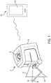
- Fig. 1 illustrates a laser generating device in the form of a laser level 12, preferably a cross-line laser level (although other types of laser levels, e.g. rotary laser levels, are possible).
- the laser level 12 includes a housing 20.
- Planar beams 50 and 52 project out of the housing 20 to form lines 54 and 56. At least when the housing 20 is placed on a flat, horizontal surface, planar beam 50 and line 54 are horizontal and planar beam 52 and line 56 are vertical.
- a laser module assembly 100 is housed inside of the housing 20, and shown in Figs. 2 and 3 .
- the laser module assembly 100 includes a pendulum 110.
- the pendulum 110 is designed to swing under the effects of gravity to provide a degree of self-leveling.
- a top of the pendulum 110 is attached to an inside of the housing 20 in a manner to allow such rotation. This may be done by a simple hinge, multiple axis hinge, wires, or in other manners, as is known in the art.
- Various self-leveling mechanisms are shown in U.S. Patent No. 6,763,595 ; U.S. Patent No. 6,763,596 and US. Patent No. 5,539,990 and the present disclosure could be applied to those configurations.
- a pair of laser modules 120 and 130 are held on the pendulum 110.
- the laser modules 120 and 130 are identical, except that they project laser beams at different orientations.
- the laser module 120 projects the beam 50 and line 54 and the laser module 130 projects the beam 52 and line 56.
- the laser modules 120, 130 are disposed on a pendulum 100 that is self-leveling, the laser modules 120, 130 project beams 50, 52 horizontally even when the housing 20 is not disposed on a perfectly flat horizontal surface. That is, if the housing 20 is held at a slight angle, the pendulum 110 rotates so that the laser modules 120, 130 maintain the appropriate orientations for projecting horizontally and vertically.
- Fig. 8 illustrates the laser modules 120 and 130.
- the laser modules 120, 130 are similar, except in orientation.
- the laser modules 120, 130 each have a laser diode 121, which generates a laser beam. They also have a collimator lens 122 and a prism 123, which convert the laser beams to lines.
- the laser module 130 is shown with a holding cylinder 124.
- the holding cylinder 124 holds the laser diode 121, collimator lens 122 and prism 123 in place and aligned properly.
- the holding cylinder 124 is omitted from the illustration of laser module 120 of Fig. 8 .
- an end of the holding cylinder 124 holding the prism 123 is shown in Figs. 2-5 .
- the laser modules may have more differences.
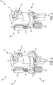
- Figs. 2 and 3 illustrate an internal structure of the laser level 12.
- the laser level 12 includes a pendulum lock 200.
- the pendulum lock 200 has a pair of arms 201 and 202. It also has a biasing spring 203 which biases the arms 201 and 202 in a direction of rotating towards one another.
- a setting projection 204 is connected to arm 201.
- the pendulum lock 200 is shown in an open (or unlocked) position in Fig. 2 and a closed (or locked) postion in Fig. 3 .
- the pendulum 110 In the open position of Fig. 2 , the pendulum 110 is able to swing to a self-leveled position. This allows the laser level 12 to project lines 54, 56 horizontally and vertically even when the housing 20 is tilted.
- the arms 201, 202 of the pendulum lock 200 clamp down on a lower portion 101 of the pendulum 110.
- the pendulum lock 200 limits movement of the pendulum 110.
- a user may wish to operate the laser level 12 with the pendulum lock 200 in the closed position in order to provide a fixed orientation for the projection laser lines 54, 56. That is, a user may simply wish for the laser lines 54, 56 to be at a fixed orientation with respect to the housing 20 rather than be free to rotate to a self-leveled position. Additionally, having the pendulum lock 200 in the closed position may provide protection for the laser module assembly 100.
- the arm 201 is operatively linked with the arm 202 through a linking section 210 so that the arms 201 and 202 move together.
- the linking section 210 includes a opening 211 which is integrally formed with the arm 201 and a pin 212 which is integrally formed with the arm 202.
- the arm 201 includes a pivot 221 about which the arm 201 pivots.
- the arm 202 includes a pivot 222, about which the arm 202 pivots.
- the biasing member in the form of a spring 203 is disposed at the pivot 222.
- the linking section 210 functions such that both arms move simultaneously between the opening and closed positions.
- the opening 211 acts as a cam, so that when the pin 212 moves, it moves along the opening 211 and causes the arm 201 to rotate. Conversely, when the arm 201 moves and the opening 211 moves along with it, the opening 211 pushes the pin 212 along the opening 211 so that the arm 202 which is connected to the pin 212 rotates.
- a lock actuator 300 is located inside the housing 20 of the laser level 12 and actuates the pendulum lock 200.
- the lock actuator 300 includes a blocking projection 301, a solenoid 302 and a biasing spring 303.
- the lock actuator 300 is in a blocking position in Fig. 2 . In the blocking position, the blocking projection 301 prevents the arm 202 of the pendulum lock 200 from moving to the closed position of Fig. 3 .
- the lock actuator 300 keeps the pendulum lock 200 in the open position shown in Fig. 2 and the pendulum 110 is able to move to self-leveling positions.
- the solenoid 302 of the lock actuator 300 is operable to move the blocking projection 301 to the release position shown in Fig. 3 .
- the blocking projection 301 is moved out of the way of the arm 202 of the pendulum lock.
- the arms 201 and 202 are moved to the closed position of Fig. 3 by the biasing spring 203 which biases the arms 201 and 202 towards the lower portion 101 of the pendulum 110 and each other.
- the arms 201 and 202 prevent movement of the pendulum 110 so that it does not rotate or self-level. As discussed above, this locked position of the pendulum 110 may be desirable for a user and may provide protection to the various parts of the laser module assembly 100.
- Figs. 4 and 5 illustrate a slide actuator 305 for opening the pendulum lock 200.
- Fig. 4 illustrates the pendulum lock 200 in a closed position where it clamps the lower portion 101 of the pendulum 110 to hold the pendulum 100 in place.
- Fig. 5 illustrates the pendulum lock 200 in the open position where the pendulum 100 may rotate.
- the slide actuator 305 can be moved, by sliding, so that it abuts against and pushes the setting projection 204.
- the slide actuator 305 pushes against the setting projector, it moves the setting projection 204.
- the setting pfojection 204 rotates about the pivot 221, the arms 201 and 202 also rotate back to the open position shown in Fig. 5 .
- the blocking projection 301 includes an end with a sloped surface 304.
- the arm 202 rotates from the closed position of Fig. 4 to the open position of Fig. 5 , the arm 202 contacts the sloped surface 304.
- the arm 202 moves against the sloped surface 304, it pushes the blocking projection 301 upwards so that the arm 202 can move past the blocking projection 301.
- the arm 202 moves past the blocking projection 301, it snaps back into a blocking position under the force of the biasing member, spring 303.
- the slide actuator 305 may project out of the housing 20 so that it may be moved by a user.
- the slide actuator 305 may be linked to a button, switch or other actuator a user may actuate to move the slide actuator 305.
- the lock actuator 300 may be engaged in multiple scenarios. As described below, it may be engaged by a user using a remote computing device 400, a button on the user interface 58 or automatically in response to a free-fall condition.
- FIG. 6 A schematic of the laser level 12 is shown in Fig. 6 .
- a battery 350 powers the various components and the solenoid 302.
- the sensor 360 is configured to detects when the laser level 12 is in a free-fall condition.
- the sensor 360 may be attached, for example, to the housing 20. In other emdobiments, the sensor 360 may be attached to the pendulum 110 or other parts of the laser level 12.
- the sensor 360 may be an accelerometer.
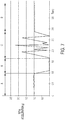
- Fig. 7 illustrates a graph of measured acceleration versus time, which may be measured by the sensor 360. Acceleration in the graph is measured on a g-force scale, in which 1.0 is typical gravity on earth. Time (t) on the scale is measured in seconds.
- the period of A shows the sensor 360 measuring a g-force of approximately 1.0.
- the laser level 12 is sitting still.
- time period B the measured g-force quickly falls to zero or near zero. This indicates that the laser level 12 is falling (under free-fall).
- time period C the measured g-force fluctuates greatly. This time period C indicates that the laser level 12 has hit the ground or other object and is bouncing.
- time period D the laser level 12 has come to rest and the sensor 360 again measures approximately 1.0 g.
- an accelerometer may determine that there is a free-fall condition when the measured g-force hits zero or near zero.
- the accelerometer may require that the measured acceleration be below a certain amount for a certain amount of time.
- the accelerometer determines that there is a free-fall condition when it measures a g-force of less than 0.1 for more than 0.1 seconds.
- the particulars of the required g-force or time can vary. It is contemplated that the free-fall may be detected by the sensor 360 in any of a variety of ways, including those described in U.S. Patent No. 8,933,801 ; U.S. Patent No. 7,328,615 or U.S. Patent No. 8,344,901 .
- the microprocessor 380 cause the lock actuator 300 to retract. Specifically, the solenoid 302 retracts the blocking projection 301 so that it moves away from the blocking position shown in Fig. 2 . This allows the arms 201 and 202 to clamp onto the bottom portion 101 of the pendulum 110, as shown in Fig. 3 and described above. Thus, when the laser level 12 falls, the laser module assembly 100 is held steady, which helps to prevent damage.
- the lock actuator 300 may retract the blocking projection 301 to activate the pendulum lock 200 when other events are detected.
- the pendulum lock 200 may be engaged automatically when the sensor detects that the laser level 12 has hit an object. This may be based on the sensor detecting a spike in g-force after a fall in g-force. For example, a spike in g-force above 1.0 after reaching near zero (0.2 or less).
- the pendulum lock 200 may also be activated by a user sending a signal to the laser level 12 through a wireless transmitter/receiver 370.
- the laser level 12 also includes a wireless transmitter/receiver 370.
- the wireless transmitter/receiver 370 is shown schematically as one component. In various embodiments it may be one or two components. Additionally, some embodiments may have only a receiver or only a transmitter and only the functionality associated therewith.
- the wireless transmitter/receiver 370 is configured to transmit and receiver wireless signals.
- the wireless signals may be received via a Bluetooth protocol, WiFi, Zigbee, infrared or other wireless transmission methods.
- the wireless transmitter/receiver 370 is connected to the microprocessor 380.
- a user may use a computing device 400 separate from the laser level 12 to send a wireless signal to the wireless transmitter/receiver 370.
- the wireless signal may be a command to activate the pendulum lock 200. As described above, this is done by retraction of the blocking projection 301 so that it moves away from the blocking position shown in Fig. 2 allowing the arms 201 and 202 clamp onto the bottom portion 101 of the pendulum 110, as shown in Fig. 3 . In this manner, a user can activate the pendulum lock 200 remotely.
- the computing device 400 may be a personal computer (PC), a tablet, a laptop, a smart phone or another computing device 400.
- the computing device may have an input so that users can input data and commands onto the computing device and a display, such as a screen 401 for displaying information to the user.
- the screen 401 may be a touch screen that functions as the input.
- Information from the sensor 360 may also be transmitted to the remote computing device 400 and displayed on the screen 401.
- the computing device 400 may display that the laser level 12 is in free-fall, that the laser level 12 has hit an object or that the laser level 12 is at rest.
- Other information to and from the laser level 12 may also be transmitted, including commands to the laser level 12 and information about the status of the laser level 12, such as whether it is on or off.
- the laser level 12 also includes a user interface 58.
- the user interface 58 includes a button which allows the user to actuate the pendulum lock 200. The user simply depresses the appropriate button on the user interface 58 and the pendulum lock 200 is activated according to the method described above.
- the laser diodes 121 of the laser modules may be powered by the battery 350.
- Switches 385 may be opened and closed to provide the appropriate connections between the battery 350, solenoid 302 and other components.
- the battery may be, for example, alkaline batteries or a power tool battery pack.
Landscapes
- Physics & Mathematics (AREA)
- Engineering & Computer Science (AREA)
- General Physics & Mathematics (AREA)
- Radar, Positioning & Navigation (AREA)
- Remote Sensing (AREA)
- Radiation-Therapy Devices (AREA)
Description
- The present invention relates to laser generating devices in the form of laser levels, particularly "self-levelling" laser levels with a system for arresting the movement of a pendulum, which pendulum enables self-levelling with respect to gravity, as is well known.
- There are various existing laser levels. It is desired to provide a laser level with a system for arresting the movement of a pendulum.
-
EP 3418687 A1 , which is a document cited under Article 54(3) EPC, discloses a laser level having a pendulum lock and a MEM sensor, and the pendulum lock may be triggered when the MEM sensor detects the freefall of the laser level. -
EP 2306147 A2 discloses a laser level according to the preamble of Claim 1 of the appendant claims. - The present invention provide a laser level according to Claim 1.
- Preferred, and other optional, features of the invention are described and defined in the dependent claims
- The laser level may further include a lock actuator, the lock actuator being movable from a blocking position to a release position.
- In the blocking position, the lock actuator may block the pendulum lock from moving to the locked position.
- In the release position, the lock actuator may allow the pendulum to move to the locked position.
- The lock actuator may move from the blocking position to the released position in response to the sensor detecting a freefall condition.
- The sensor may be an accelerometer.
- The pendulum lock may include a biasing member which biases the pendulum lock towards the locked position.
- The laser level may further include a user actuated switch which moves the pendulum lock to the unlocked position.
- The biasing member may include a spring.
- The laser module assembly may produce at least one line which is configured to project against a surface outside the housing.
- The laser module assembly may produce a first line which projects against a surface outside the housing and a second line which projects against the surface.
- The first line is generally perpendicular to the second line.
- The laser level may projects multiple lines onto a surface remote from the laser level.
- The laser level may project one or more dots onto a surface remote from the laser level.
- The laser level may projects a rotating laser onto a surface remote from the laser level.
- The laser level housing may be made of plastic.
- The laser level housing may be made of multiple plastic housing parts attached together.
- The laser level may further include a controller housed in the housing and operatively connected to the sensor.
- In the blocking position, the lock actuator may block the pendulum lock from moving from the unlocked position to the locked position.
- In the release position, the lock actuator may allow the pendulum to move to the locked position.
- The lock actuator may include a solendoid for moving the lock actuator.
- The controller may control operation of the solenoid.
- The laser level may further include a wireless transmitter.
- The wireless transmitter may transmit a signal to a remote electronic device when the sensor detects a freefall condition.
- The remote electronic device may provide a display to a user in response to detection of the freefall condition.
- The remote electronic device may be a computing device.
- The laser level may further include a wireless receiver configured to receive wireless signals.
- The controller may be configured to move the lock actuator to the release position in response to receiving a lock actuation command through the wireless receiver from a remote electronic device.
- Another aspect of the invention provides a system comprising a said laser level and a said electronic device.
- An embodiment of the invention will now be described, by way of example, with reference to the accompanying figures, of which:
-
Fig. 1 illustrates a perspective view of a laser level according to an exemplary embodiment of the invention; -
Fig. 2 is a perspective view of a laser module assembly of the laser level according to the exemplary embodiment; -
Fig. 3 is another perspective view of a laser module assembly of the laser level according to the exemplary embodiment; -
Fig. 4 is another perspective view of a laser module assembly of the laser level according to the exemplary embodiment; -
Fig. 5 is another perspective view of a laser module assembly of the laser level according to the exemplary embodiment;; -
Fig. 6 schematic circuit diagram of the laser level according to the exemplary embodiment; -
Fig. 7 is a graph of a sensor reading of a sensor of the laser level of the exemplary embodiment; and -
Fig. 8 are side views of laser modules of the laser level of the exemplary embodiment. - An exemplary embodiment of the invention is shown in
Figs. 1-8 .Fig. 1 illustrates a laser generating device in the form of alaser level 12, preferably a cross-line laser level (although other types of laser levels, e.g. rotary laser levels, are possible). Thelaser level 12 includes ahousing 20. Planar beams 50 and 52 project out of thehousing 20 to formlines housing 20 is placed on a flat, horizontal surface,planar beam 50 andline 54 are horizontal andplanar beam 52 andline 56 are vertical. - A
laser module assembly 100 is housed inside of thehousing 20, and shown inFigs. 2 and 3 . Thelaser module assembly 100 includes apendulum 110. Thependulum 110 is designed to swing under the effects of gravity to provide a degree of self-leveling. A top of thependulum 110 is attached to an inside of thehousing 20 in a manner to allow such rotation. This may be done by a simple hinge, multiple axis hinge, wires, or in other manners, as is known in the art. Various self-leveling mechanisms are shown inU.S. Patent No. 6,763,595 ;U.S. Patent No. 6,763,596 andUS. Patent No. 5,539,990 and the present disclosure could be applied to those configurations. - A pair of
laser modules pendulum 110. Thelaser modules laser module 120 projects thebeam 50 andline 54 and thelaser module 130 projects thebeam 52 andline 56. Since thelaser modules pendulum 100 that is self-leveling, thelaser modules project beams housing 20 is not disposed on a perfectly flat horizontal surface. That is, if thehousing 20 is held at a slight angle, thependulum 110 rotates so that thelaser modules -
Fig. 8 illustrates thelaser modules laser modules Fig. 8 , thelaser modules laser diode 121, which generates a laser beam. They also have acollimator lens 122 and aprism 123, which convert the laser beams to lines. Thelaser module 130 is shown with a holdingcylinder 124. The holdingcylinder 124 holds thelaser diode 121,collimator lens 122 andprism 123 in place and aligned properly. The holdingcylinder 124 is omitted from the illustration oflaser module 120 ofFig. 8 . Additionally, an end of the holdingcylinder 124 holding theprism 123 is shown inFigs. 2-5 . In other embodiments, the laser modules may have more differences. -
Figs. 2 and 3 illustrate an internal structure of thelaser level 12. As shown inFigs. 2 and 3 , thelaser level 12 includes apendulum lock 200. Thependulum lock 200 has a pair ofarms spring 203 which biases thearms projection 204 is connected toarm 201. - The
pendulum lock 200 is shown in an open (or unlocked) position inFig. 2 and a closed (or locked) postion inFig. 3 . In the open position ofFig. 2 , thependulum 110 is able to swing to a self-leveled position. This allows thelaser level 12 to project lines 54, 56 horizontally and vertically even when thehousing 20 is tilted. In the closed position shown inFig. 3 , thearms pendulum lock 200 clamp down on alower portion 101 of thependulum 110. Thus, in the closed position ofFig. 3 , thependulum lock 200 limits movement of thependulum 110. - A user may wish to operate the
laser level 12 with thependulum lock 200 in the closed position in order to provide a fixed orientation for theprojection laser lines laser lines housing 20 rather than be free to rotate to a self-leveled position. Additionally, having thependulum lock 200 in the closed position may provide protection for thelaser module assembly 100. - The
arm 201 is operatively linked with thearm 202 through a linkingsection 210 so that thearms section 210 includes aopening 211 which is integrally formed with thearm 201 and apin 212 which is integrally formed with thearm 202. Thearm 201 includes apivot 221 about which thearm 201 pivots. Similarly, thearm 202 includes a pivot 222, about which thearm 202 pivots. The biasing member in the form of aspring 203 is disposed at the pivot 222. - The linking
section 210 functions such that both arms move simultaneously between the opening and closed positions. In particular, the opening 211 acts as a cam, so that when thepin 212 moves, it moves along theopening 211 and causes thearm 201 to rotate. Conversely, when thearm 201 moves and theopening 211 moves along with it, theopening 211 pushes thepin 212 along theopening 211 so that thearm 202 which is connected to thepin 212 rotates. - As shown in
Figs. 2 and 3 , alock actuator 300 is located inside thehousing 20 of thelaser level 12 and actuates thependulum lock 200. Thelock actuator 300 includes a blockingprojection 301, asolenoid 302 and abiasing spring 303. Thelock actuator 300 is in a blocking position inFig. 2 . In the blocking position, the blockingprojection 301 prevents thearm 202 of thependulum lock 200 from moving to the closed position ofFig. 3 . Thus, thelock actuator 300 keeps thependulum lock 200 in the open position shown inFig. 2 and thependulum 110 is able to move to self-leveling positions. - The
solenoid 302 of thelock actuator 300 is operable to move the blockingprojection 301 to the release position shown inFig. 3 . In the release position, the blockingprojection 301 is moved out of the way of thearm 202 of the pendulum lock. This allows thelock arms lower portion 101 of thependulum 110. Thearms Fig. 3 by the biasingspring 203 which biases thearms lower portion 101 of thependulum 110 and each other. When thependulum lock 200 is in the closed position inFig. 3 , thearms pendulum 110 so that it does not rotate or self-level. As discussed above, this locked position of thependulum 110 may be desirable for a user and may provide protection to the various parts of thelaser module assembly 100. -
Figs. 4 and 5 illustrate aslide actuator 305 for opening thependulum lock 200.Fig. 4 illustrates thependulum lock 200 in a closed position where it clamps thelower portion 101 of thependulum 110 to hold thependulum 100 in place.Fig. 5 illustrates thependulum lock 200 in the open position where thependulum 100 may rotate. As shown inFigs. 4 and 5 , theslide actuator 305 can be moved, by sliding, so that it abuts against and pushes the settingprojection 204. As theslide actuator 305 pushes against the setting projector, it moves the settingprojection 204. As thesetting pfojection 204 rotates about thepivot 221, thearms Fig. 5 . - As shown in
Fig. 5 , the blockingprojection 301 includes an end with a sloped surface 304. As will be appreciated, as thearm 202 rotates from the closed position ofFig. 4 to the open position ofFig. 5 , thearm 202 contacts the sloped surface 304. As thearm 202 moves against the sloped surface 304, it pushes the blockingprojection 301 upwards so that thearm 202 can move past the blockingprojection 301. After thearm 202 moves past the blockingprojection 301, it snaps back into a blocking position under the force of the biasing member,spring 303. - The
slide actuator 305 may project out of thehousing 20 so that it may be moved by a user. In other embodiments, theslide actuator 305 may be linked to a button, switch or other actuator a user may actuate to move theslide actuator 305. - The
lock actuator 300 may be engaged in multiple scenarios. As described below, it may be engaged by a user using aremote computing device 400, a button on theuser interface 58 or automatically in response to a free-fall condition. - A schematic of the
laser level 12 is shown inFig. 6 . As shown inFig. 6 , there is abattery 350, asensor 360, a wireless receiver/transmitter 370 and amicroprocessor 380. Thebattery 350 powers the various components and thesolenoid 302. Thesensor 360 is configured to detects when thelaser level 12 is in a free-fall condition. Thesensor 360 may be attached, for example, to thehousing 20. In other emdobiments, thesensor 360 may be attached to thependulum 110 or other parts of thelaser level 12. Thesensor 360 may be an accelerometer. -
Fig. 7 illustrates a graph of measured acceleration versus time, which may be measured by thesensor 360. Acceleration in the graph is measured on a g-force scale, in which 1.0 is typical gravity on earth. Time (t) on the scale is measured in seconds. - In
Fig. 7 , the period of A shows thesensor 360 measuring a g-force of approximately 1.0. In this time period A, thelaser level 12 is sitting still. In time period B, the measured g-force quickly falls to zero or near zero. This indicates that thelaser level 12 is falling (under free-fall). In the time period C, the measured g-force fluctuates greatly. This time period C indicates that thelaser level 12 has hit the ground or other object and is bouncing. Finally, in time period D, thelaser level 12 has come to rest and thesensor 360 again measures approximately 1.0 g. - Various accelerometers or other sensors determine a free-fall condition in different ways. For example, an accelerometer may determine that there is a free-fall condition when the measured g-force hits zero or near zero. In some instances, the accelerometer may require that the measured acceleration be below a certain amount for a certain amount of time. For example, the accelerometer determines that there is a free-fall condition when it measures a g-force of less than 0.1 for more than 0.1 seconds. The particulars of the required g-force or time can vary. It is contemplated that the free-fall may be detected by the
sensor 360 in any of a variety of ways, including those described inU.S. Patent No. 8,933,801 ;U.S. Patent No. 7,328,615 orU.S. Patent No. 8,344,901 . - Once a free fall is detected by the
sensor 360, themicroprocessor 380 cause thelock actuator 300 to retract. Specifically, thesolenoid 302 retracts the blockingprojection 301 so that it moves away from the blocking position shown inFig. 2 . This allows thearms bottom portion 101 of thependulum 110, as shown inFig. 3 and described above. Thus, when thelaser level 12 falls, thelaser module assembly 100 is held steady, which helps to prevent damage. - In other embodiments, the
lock actuator 300 may retract the blockingprojection 301 to activate thependulum lock 200 when other events are detected. For example, alternatively or additionally, thependulum lock 200 may be engaged automatically when the sensor detects that thelaser level 12 has hit an object. This may be based on the sensor detecting a spike in g-force after a fall in g-force. For example, a spike in g-force above 1.0 after reaching near zero (0.2 or less). - The
pendulum lock 200 may also be activated by a user sending a signal to thelaser level 12 through a wireless transmitter/receiver 370. - As shown in
Fig. 6 , thelaser level 12 also includes a wireless transmitter/receiver 370. In the exemplary embodiment shown inFig. 6 , the wireless transmitter/receiver 370 is shown schematically as one component. In various embodiments it may be one or two components. Additionally, some embodiments may have only a receiver or only a transmitter and only the functionality associated therewith. - The wireless transmitter/
receiver 370 is configured to transmit and receiver wireless signals. The wireless signals may be received via a Bluetooth protocol, WiFi, Zigbee, infrared or other wireless transmission methods. As shown, the wireless transmitter/receiver 370 is connected to themicroprocessor 380. - A user may use a
computing device 400 separate from thelaser level 12 to send a wireless signal to the wireless transmitter/receiver 370. The wireless signal may be a command to activate thependulum lock 200. As described above, this is done by retraction of the blockingprojection 301 so that it moves away from the blocking position shown inFig. 2 allowing thearms bottom portion 101 of thependulum 110, as shown inFig. 3 . In this manner, a user can activate thependulum lock 200 remotely. - The
computing device 400 may be a personal computer (PC), a tablet, a laptop, a smart phone or anothercomputing device 400. The computing device may have an input so that users can input data and commands onto the computing device and a display, such as ascreen 401 for displaying information to the user. Thescreen 401 may be a touch screen that functions as the input. - Information from the
sensor 360 may also be transmitted to theremote computing device 400 and displayed on thescreen 401. For example, thecomputing device 400 may display that thelaser level 12 is in free-fall, that thelaser level 12 has hit an object or that thelaser level 12 is at rest. Other information to and from thelaser level 12 may also be transmitted, including commands to thelaser level 12 and information about the status of thelaser level 12, such as whether it is on or off. - As shown in
Figs. 1 and6 , thelaser level 12 also includes auser interface 58. Theuser interface 58 includes a button which allows the user to actuate thependulum lock 200. The user simply depresses the appropriate button on theuser interface 58 and thependulum lock 200 is activated according to the method described above. - As shown in
Fig. 6 , thelaser diodes 121 of the laser modules may be powered by thebattery 350.Switches 385 may be opened and closed to provide the appropriate connections between thebattery 350,solenoid 302 and other components. The battery may be, for example, alkaline batteries or a power tool battery pack.
Claims (15)
- A laser level (12), comprising:a housing (20);a laser module assembly (100) at least partially housed in the housing (20), the laser module assembly (100) comprising: a pendulum assembly (110) configured to rotate under the effect of gravity; and at least one laser module (120) disposed on the pendulum assembly (110), the laser module (120) comprising a laser generator which is configured to generate a laser beam (50, 52) emitted from the laser level (12) in use;a pendulum lock (200) at least partially housed in the housing (20) and movable from an unlocked position to a locked position, wherein when the pendulum lock (200) is in the locked position it substantially prevents the pendulum assembly (110) from rotating;characterized by a sensor (360) disposed in or on the housing (20) and configured to detect a freefall condition comprising a measured acceleration of no greater than 0.5g, wherein the laser level (12) is configured such that the pendulum lock (200) moves from the unlocked position to the locked position when the sensor (360) detects the freefall condition in use.
- A laser level (12) according to Claim 1, wherein the sensor (360) comprises at least one accelerometer.
- A laser level (12) according to Claim 1 or Claim 2, further comprising a lock actuator (300) configured to cause or enable the pendulum lock (200) to move from the unlocked position to the locked position when the sensor (360) detects the freefall condition.
- A laser level (12) according to Claim 3, wherein at least a part of the lock actuator (300) is movable from a blocking position to a release position; wherein, in the blocking position, the lock actuator (300) blocks the pendulum lock (200) from moving from the unlocked position to the locked position; and wherein, in the release position, the lock actuator (300) causes or enables the pendulum lock (200) to move to the locked position.
- A laser level (12) according to Claim 3 or Claim 4, further comprising a controller (380) housed in the housing (20) and operatively connected to the sensor (360) and to the lock actuator (300).
- A laser level (12) according to Claim 4, or Claim 5 when dependent on Claim 4, wherein the lock actuator (300) includes a solenoid (302) configured to move the movable part of the lock actuator (300) when the sensor (360) detects the freefall condition.
- A laser level (12) according to Claim 6 when dependent upon Claim 5, wherein the controller (380) is configured to operate the solenoid (302).
- A laser level (12) according to any preceding claim, wherein the pendulum lock (200) includes a biasing member (203), preferably a spring, which biases the pendulum lock (200) towards the locked position.
- A laser level (12) according to any preceding claim, further comprising a user actuated switch (305) configured to move the pendulum lock (200) to the unlocked position.
- A laser level (12) according to any preceding claim, wherein the laser module assembly (100) is configured to produce at least one laser beam line (54, 56) projected onto a wall or other surface exterior to the housing (20) of the laser level (12).
- A laser level (12) according to Claim 10, wherein the laser module assembly (100) is configured to produce first and second such laser beam lines (54, 56), wherein the second laser beam line is substantially perpendicular to the first laser beam line.
- A laser level (12) according to any preceding claim, wherein the laser module assembly (100) and/or the pendulum lock (200) is/are entirely housed in the housing (20).
- A laser level (12) according to any preceding claim, wherein the freefall condition comprises a measured acceleration of no greater than 0.3g, more preferably no greater than 0.1g, each preferably for at least 0.1 seconds.
- A laser level (12) according to any preceding claim, further comprising a wireless transmitter (370) configured to transmit a signal, containing information concerning the freefall condition, to the exterior of the housing (20), preferably to a remote electronic device (400), when the sensor (360) detects the freefall condition.
- A laser level (12) according to Claim 5 or any claim dependent thereon, further comprising a wireless receiver (370) configured to receive wireless signals from the exterior of the housing (20), preferably from a remote electronic device (400), and wherein the controller (380) is configured to move the lock actuator (300) to the release position in response to receiving a lock actuation command via the wireless receiver (370).
Applications Claiming Priority (2)
| Application Number | Priority Date | Filing Date | Title |
|---|---|---|---|
| US201762554740P | 2017-09-06 | 2017-09-06 | |
| US16/100,355 US10982958B2 (en) | 2017-09-06 | 2018-08-10 | Laser level pendulum arrest |
Publications (2)
| Publication Number | Publication Date |
|---|---|
| EP3454009A1 EP3454009A1 (en) | 2019-03-13 |
| EP3454009B1 true EP3454009B1 (en) | 2020-06-17 |
Family
ID=63517812
Family Applications (1)
| Application Number | Title | Priority Date | Filing Date |
|---|---|---|---|
| EP18192818.5A Active EP3454009B1 (en) | 2017-09-06 | 2018-09-05 | Laser level |
Country Status (3)
| Country | Link |
|---|---|
| US (1) | US10982958B2 (en) |
| EP (1) | EP3454009B1 (en) |
| CN (1) | CN209043319U (en) |
Families Citing this family (11)
| Publication number | Priority date | Publication date | Assignee | Title |
|---|---|---|---|---|
| DE102016205089A1 (en) * | 2016-03-29 | 2017-10-05 | Robert Bosch Gmbh | Leveling device with a pendulating light generating unit |
| US10881362B2 (en) * | 2018-11-20 | 2021-01-05 | General Electric Company | Systems for laser alignment |
| US11320263B2 (en) * | 2019-01-25 | 2022-05-03 | Stanley Black & Decker Inc. | Laser level system |
| USD929248S1 (en) * | 2019-10-10 | 2021-08-31 | Aukey Technology Co., Ltd | Laser level |
| CN112857332A (en) * | 2019-11-27 | 2021-05-28 | 苏州宝时得电动工具有限公司 | Laser level meter |
| US11307030B2 (en) * | 2020-02-10 | 2022-04-19 | Joseph Michaud | Laser detector mounting device |
| CN112033384A (en) * | 2020-09-03 | 2020-12-04 | 珠海镭沃科技有限公司 | Laser demarcation device with angle detection function |
| US12498221B2 (en) | 2021-08-10 | 2025-12-16 | Topcon Corporation | System, device, and control method |
| JP2023025466A (en) * | 2021-08-10 | 2023-02-22 | 株式会社トプコン | Survey system, survey device, and control method |
| JP2023025465A (en) * | 2021-08-10 | 2023-02-22 | 株式会社トプコン | Rotary laser system, rotary laser device, and control method |
| DE112023001190T5 (en) * | 2022-05-31 | 2024-12-24 | Milwaukee Electric Tool Corporation | ROTATIONAL LASER CORE |
Family Cites Families (32)
| Publication number | Priority date | Publication date | Assignee | Title |
|---|---|---|---|---|
| IT1275249B (en) * | 1995-02-22 | 1997-07-31 | Micro Italiana Spa | PROJECTOR DEVICE OF ONE OR MORE FLAT BANDS OF DIVERGENT SELF-LEVELING GRAVITY LASER BEAMS FOR THE PROJECTION OF ONE OR MORE HORIZONTAL AND / OR VERTICAL STRAIGHT ON WALL OR SIMILAR BODIES |
| US5539990A (en) * | 1995-05-30 | 1996-07-30 | Le; Mike | Three-dimensional optical levelling, plumbing and angle-calibrating instrument |
| US5680208A (en) * | 1996-03-01 | 1997-10-21 | Dwbh Ventures Ltd. | Gravity oriented laser scanner |
| US6914930B2 (en) | 2002-05-31 | 2005-07-05 | Black & Decker Inc. | Laser level |
| US6763595B1 (en) * | 2002-06-21 | 2004-07-20 | Pls - Pacific Laser Systems | Laser-based tool for indicating level, plumb and square |
| US6763596B1 (en) * | 2002-08-23 | 2004-07-20 | Chicago Steel Tape Co. | Laser alignment device |
| US7523558B2 (en) | 2002-10-22 | 2009-04-28 | Black And Decker | Tool incorporating a light line generating device |
| JP4198018B2 (en) | 2003-10-03 | 2008-12-17 | 三洋電機株式会社 | Laser line marker |
| EP1525962A3 (en) | 2003-10-20 | 2005-12-28 | Western Printing Machinery Company | Knife assembly for a rotary cutter |
| KR100618866B1 (en) | 2004-10-02 | 2006-08-31 | 삼성전자주식회사 | Free fall detection method and apparatus of electronic equipment |
| US7382567B2 (en) | 2005-05-09 | 2008-06-03 | Analog Devices, Inc. | Accelerometer-based differential free fall detection system, apparatus, and method and disk drive protection mechanism employing same |
| US7403131B2 (en) | 2005-06-21 | 2008-07-22 | The Boeing Company | Power tool movement monitor and operating system |
| US20070044331A1 (en) * | 2005-08-26 | 2007-03-01 | Billy Yung | Laser leveler with ultrasonic transmitter and receiver |
| JP4993554B2 (en) * | 2005-11-22 | 2012-08-08 | 株式会社オーディオテクニカ | Inking machine |
| US8814641B2 (en) | 2006-05-08 | 2014-08-26 | Nintendo Co., Ltd. | System and method for detecting moment of impact and/or strength of a swing based on accelerometer data |
| CN101078623B (en) | 2006-05-26 | 2010-05-12 | 南京德朔实业有限公司 | Self-leveling laser marking device and control method thereof |
| US7454839B2 (en) * | 2006-08-22 | 2008-11-25 | Robotoolz, Ltd. | Portable reference laser unit and attachment accessory |
| JP4197530B2 (en) * | 2006-11-01 | 2008-12-17 | 株式会社オーディオテクニカ | Laser marking machine |
| US7571546B1 (en) * | 2008-02-01 | 2009-08-11 | Black And Decker | Light line generating device |
| US8044818B2 (en) | 2009-01-27 | 2011-10-25 | Research In Motion Limited | Method and handheld electronic device for detecting and providing notification of a device drop |
| DE102009045324B3 (en) | 2009-10-05 | 2011-05-05 | Robert Bosch Gmbh | Pendulum laser device with lockable pendulum arrangement |
| JP5616174B2 (en) | 2010-09-14 | 2014-10-29 | 株式会社トプコン | Laser surveying equipment |
| FR2966238A1 (en) | 2010-10-13 | 2012-04-20 | Psp Outil | LASER LEVEL COMPRISING A MOTION DETECTION MODULE. |
| FR2966237A1 (en) | 2010-10-13 | 2012-04-20 | Psp Outil | ANGULAR INDICATION ON A REMOTE CONTROL AND QUICK SETTING OF A LASER LEVEL. |
| US8843345B2 (en) | 2011-06-20 | 2014-09-23 | Invensense, Inc. | Motion determination |
| US9441963B2 (en) * | 2012-02-17 | 2016-09-13 | Robert Bosch Company Limited | Multifunction laser leveling tool |
| US20140267703A1 (en) | 2013-03-15 | 2014-09-18 | Robert M. Taylor | Method and Apparatus of Mapping Landmark Position and Orientation |
| US8933801B2 (en) | 2013-04-19 | 2015-01-13 | Linear Llc | Fall detection system and method |
| US9441967B2 (en) * | 2013-05-31 | 2016-09-13 | Stanley Black & Decker Inc. | Laser level system |
| DE102015223643B4 (en) * | 2015-11-30 | 2018-02-22 | Robert Bosch Gmbh | Method for producing a pendulum arrangement of a pendulum laser device and pendulum laser device |
| CN109099897A (en) | 2017-06-20 | 2018-12-28 | 罗伯特·博世有限公司 | Laser level and its automatic locking method with automatic locking system |
| CN109211206A (en) | 2017-07-06 | 2019-01-15 | 罗伯特·博世有限公司 | Line laser line marker pendulum type with calibration defencive function |
-
2018
- 2018-08-10 US US16/100,355 patent/US10982958B2/en active Active
- 2018-09-05 EP EP18192818.5A patent/EP3454009B1/en active Active
- 2018-09-05 CN CN201821447807.XU patent/CN209043319U/en not_active Expired - Fee Related
Non-Patent Citations (1)
| Title |
|---|
| None * |
Also Published As
| Publication number | Publication date |
|---|---|
| CN209043319U (en) | 2019-06-28 |
| US10982958B2 (en) | 2021-04-20 |
| EP3454009A1 (en) | 2019-03-13 |
| US20190072385A1 (en) | 2019-03-07 |
Similar Documents
| Publication | Publication Date | Title |
|---|---|---|
| US10982958B2 (en) | Laser level pendulum arrest | |
| US7059182B1 (en) | Active impact protection system | |
| KR102183489B1 (en) | Device for detecting the state of a leaf of doors, gates and the like | |
| CN114246409A (en) | Dynamic latch for hinge assembly | |
| US8284162B2 (en) | Manual pointing device for a computer system with inertial click event detection and corresponding click event detection method | |
| US20180345498A1 (en) | Determining the movement of a machine to be secured | |
| CN108475458B (en) | Window sensing device with motion detection | |
| EP3878312B1 (en) | Unit for controlling safe operation of an electric table | |
| EP1926064B1 (en) | Method for setting a programmable allowed movement time on an asset protection device | |
| EP3020220B1 (en) | Device and method for controlling access to at least one machine | |
| JP2026031693A (en) | Surveying system and surveying system control method | |
| EP3418687A1 (en) | Laser levelling apparatus with auto locking system and auto locking method | |
| CN109899638A (en) | A kind of self hang down type photoelectric instrument | |
| JPH09115077A (en) | Photoelectric sensor | |
| TW202131144A (en) | Portable device | |
| WO2020154495A1 (en) | Motion sensing cable | |
| US10900993B2 (en) | Single axis accelerometer with inertial threshold | |
| KR102172180B1 (en) | Communication Cable Connection Router | |
| CN209638669U (en) | A kind of self hang down type photoelectric instrument | |
| CN212513020U (en) | Line projector | |
| US11937677B2 (en) | Luggage | |
| KR102172178B1 (en) | Indoor Internet Communication Router | |
| US3581577A (en) | Acceleration-sensitive actuator | |
| US20240418483A1 (en) | Target Positioning and Control System | |
| CN223180415U (en) | earthquake sensors |
Legal Events
| Date | Code | Title | Description |
|---|---|---|---|
| PUAI | Public reference made under article 153(3) epc to a published international application that has entered the european phase |
Free format text: ORIGINAL CODE: 0009012 |
|
| STAA | Information on the status of an ep patent application or granted ep patent |
Free format text: STATUS: THE APPLICATION HAS BEEN PUBLISHED |
|
| AK | Designated contracting states |
Kind code of ref document: A1 Designated state(s): AL AT BE BG CH CY CZ DE DK EE ES FI FR GB GR HR HU IE IS IT LI LT LU LV MC MK MT NL NO PL PT RO RS SE SI SK SM TR |
|
| AX | Request for extension of the european patent |
Extension state: BA ME |
|
| STAA | Information on the status of an ep patent application or granted ep patent |
Free format text: STATUS: REQUEST FOR EXAMINATION WAS MADE |
|
| 17P | Request for examination filed |
Effective date: 20190911 |
|
| RBV | Designated contracting states (corrected) |
Designated state(s): AL AT BE BG CH CY CZ DE DK EE ES FI FR GB GR HR HU IE IS IT LI LT LU LV MC MK MT NL NO PL PT RO RS SE SI SK SM TR |
|
| GRAP | Despatch of communication of intention to grant a patent |
Free format text: ORIGINAL CODE: EPIDOSNIGR1 |
|
| STAA | Information on the status of an ep patent application or granted ep patent |
Free format text: STATUS: GRANT OF PATENT IS INTENDED |
|
| RIC1 | Information provided on ipc code assigned before grant |
Ipc: G01P 15/08 20060101ALN20191220BHEP Ipc: G01C 15/00 20060101AFI20191220BHEP |
|
| INTG | Intention to grant announced |
Effective date: 20200122 |
|
| RIN1 | Information on inventor provided before grant (corrected) |
Inventor name: STERN, IDO Inventor name: EIDINGER, BRUCE Inventor name: LOMBARDI, KEITH M. |
|
| GRAS | Grant fee paid |
Free format text: ORIGINAL CODE: EPIDOSNIGR3 |
|
| GRAA | (expected) grant |
Free format text: ORIGINAL CODE: 0009210 |
|
| STAA | Information on the status of an ep patent application or granted ep patent |
Free format text: STATUS: THE PATENT HAS BEEN GRANTED |
|
| AK | Designated contracting states |
Kind code of ref document: B1 Designated state(s): AL AT BE BG CH CY CZ DE DK EE ES FI FR GB GR HR HU IE IS IT LI LT LU LV MC MK MT NL NO PL PT RO RS SE SI SK SM TR |
|
| REG | Reference to a national code |
Ref country code: GB Ref legal event code: FG4D |
|
| REG | Reference to a national code |
Ref country code: CH Ref legal event code: EP |
|
| REG | Reference to a national code |
Ref country code: IE Ref legal event code: FG4D |
|
| REG | Reference to a national code |
Ref country code: DE Ref legal event code: R096 Ref document number: 602018005338 Country of ref document: DE |
|
| REG | Reference to a national code |
Ref country code: AT Ref legal event code: REF Ref document number: 1281846 Country of ref document: AT Kind code of ref document: T Effective date: 20200715 |
|
| PG25 | Lapsed in a contracting state [announced via postgrant information from national office to epo] |
Ref country code: SE Free format text: LAPSE BECAUSE OF FAILURE TO SUBMIT A TRANSLATION OF THE DESCRIPTION OR TO PAY THE FEE WITHIN THE PRESCRIBED TIME-LIMIT Effective date: 20200617 Ref country code: FI Free format text: LAPSE BECAUSE OF FAILURE TO SUBMIT A TRANSLATION OF THE DESCRIPTION OR TO PAY THE FEE WITHIN THE PRESCRIBED TIME-LIMIT Effective date: 20200617 Ref country code: NO Free format text: LAPSE BECAUSE OF FAILURE TO SUBMIT A TRANSLATION OF THE DESCRIPTION OR TO PAY THE FEE WITHIN THE PRESCRIBED TIME-LIMIT Effective date: 20200917 Ref country code: GR Free format text: LAPSE BECAUSE OF FAILURE TO SUBMIT A TRANSLATION OF THE DESCRIPTION OR TO PAY THE FEE WITHIN THE PRESCRIBED TIME-LIMIT Effective date: 20200918 Ref country code: LT Free format text: LAPSE BECAUSE OF FAILURE TO SUBMIT A TRANSLATION OF THE DESCRIPTION OR TO PAY THE FEE WITHIN THE PRESCRIBED TIME-LIMIT Effective date: 20200617 |
|
| REG | Reference to a national code |
Ref country code: LT Ref legal event code: MG4D |
|
| REG | Reference to a national code |
Ref country code: NL Ref legal event code: MP Effective date: 20200617 |
|
| PG25 | Lapsed in a contracting state [announced via postgrant information from national office to epo] |
Ref country code: LV Free format text: LAPSE BECAUSE OF FAILURE TO SUBMIT A TRANSLATION OF THE DESCRIPTION OR TO PAY THE FEE WITHIN THE PRESCRIBED TIME-LIMIT Effective date: 20200617 Ref country code: RS Free format text: LAPSE BECAUSE OF FAILURE TO SUBMIT A TRANSLATION OF THE DESCRIPTION OR TO PAY THE FEE WITHIN THE PRESCRIBED TIME-LIMIT Effective date: 20200617 Ref country code: BG Free format text: LAPSE BECAUSE OF FAILURE TO SUBMIT A TRANSLATION OF THE DESCRIPTION OR TO PAY THE FEE WITHIN THE PRESCRIBED TIME-LIMIT Effective date: 20200917 Ref country code: HR Free format text: LAPSE BECAUSE OF FAILURE TO SUBMIT A TRANSLATION OF THE DESCRIPTION OR TO PAY THE FEE WITHIN THE PRESCRIBED TIME-LIMIT Effective date: 20200617 |
|
| REG | Reference to a national code |
Ref country code: AT Ref legal event code: MK05 Ref document number: 1281846 Country of ref document: AT Kind code of ref document: T Effective date: 20200617 |
|
| PG25 | Lapsed in a contracting state [announced via postgrant information from national office to epo] |
Ref country code: AL Free format text: LAPSE BECAUSE OF FAILURE TO SUBMIT A TRANSLATION OF THE DESCRIPTION OR TO PAY THE FEE WITHIN THE PRESCRIBED TIME-LIMIT Effective date: 20200617 Ref country code: NL Free format text: LAPSE BECAUSE OF FAILURE TO SUBMIT A TRANSLATION OF THE DESCRIPTION OR TO PAY THE FEE WITHIN THE PRESCRIBED TIME-LIMIT Effective date: 20200617 |
|
| PG25 | Lapsed in a contracting state [announced via postgrant information from national office to epo] |
Ref country code: CZ Free format text: LAPSE BECAUSE OF FAILURE TO SUBMIT A TRANSLATION OF THE DESCRIPTION OR TO PAY THE FEE WITHIN THE PRESCRIBED TIME-LIMIT Effective date: 20200617 Ref country code: RO Free format text: LAPSE BECAUSE OF FAILURE TO SUBMIT A TRANSLATION OF THE DESCRIPTION OR TO PAY THE FEE WITHIN THE PRESCRIBED TIME-LIMIT Effective date: 20200617 Ref country code: EE Free format text: LAPSE BECAUSE OF FAILURE TO SUBMIT A TRANSLATION OF THE DESCRIPTION OR TO PAY THE FEE WITHIN THE PRESCRIBED TIME-LIMIT Effective date: 20200617 Ref country code: SM Free format text: LAPSE BECAUSE OF FAILURE TO SUBMIT A TRANSLATION OF THE DESCRIPTION OR TO PAY THE FEE WITHIN THE PRESCRIBED TIME-LIMIT Effective date: 20200617 Ref country code: IT Free format text: LAPSE BECAUSE OF FAILURE TO SUBMIT A TRANSLATION OF THE DESCRIPTION OR TO PAY THE FEE WITHIN THE PRESCRIBED TIME-LIMIT Effective date: 20200617 Ref country code: AT Free format text: LAPSE BECAUSE OF FAILURE TO SUBMIT A TRANSLATION OF THE DESCRIPTION OR TO PAY THE FEE WITHIN THE PRESCRIBED TIME-LIMIT Effective date: 20200617 Ref country code: PT Free format text: LAPSE BECAUSE OF FAILURE TO SUBMIT A TRANSLATION OF THE DESCRIPTION OR TO PAY THE FEE WITHIN THE PRESCRIBED TIME-LIMIT Effective date: 20201019 Ref country code: ES Free format text: LAPSE BECAUSE OF FAILURE TO SUBMIT A TRANSLATION OF THE DESCRIPTION OR TO PAY THE FEE WITHIN THE PRESCRIBED TIME-LIMIT Effective date: 20200617 |
|
| PG25 | Lapsed in a contracting state [announced via postgrant information from national office to epo] |
Ref country code: SK Free format text: LAPSE BECAUSE OF FAILURE TO SUBMIT A TRANSLATION OF THE DESCRIPTION OR TO PAY THE FEE WITHIN THE PRESCRIBED TIME-LIMIT Effective date: 20200617 Ref country code: PL Free format text: LAPSE BECAUSE OF FAILURE TO SUBMIT A TRANSLATION OF THE DESCRIPTION OR TO PAY THE FEE WITHIN THE PRESCRIBED TIME-LIMIT Effective date: 20200617 Ref country code: IS Free format text: LAPSE BECAUSE OF FAILURE TO SUBMIT A TRANSLATION OF THE DESCRIPTION OR TO PAY THE FEE WITHIN THE PRESCRIBED TIME-LIMIT Effective date: 20201017 |
|
| REG | Reference to a national code |
Ref country code: DE Ref legal event code: R097 Ref document number: 602018005338 Country of ref document: DE |
|
| PLBE | No opposition filed within time limit |
Free format text: ORIGINAL CODE: 0009261 |
|
| STAA | Information on the status of an ep patent application or granted ep patent |
Free format text: STATUS: NO OPPOSITION FILED WITHIN TIME LIMIT |
|
| PG25 | Lapsed in a contracting state [announced via postgrant information from national office to epo] |
Ref country code: DK Free format text: LAPSE BECAUSE OF FAILURE TO SUBMIT A TRANSLATION OF THE DESCRIPTION OR TO PAY THE FEE WITHIN THE PRESCRIBED TIME-LIMIT Effective date: 20200617 |
|
| 26N | No opposition filed |
Effective date: 20210318 |
|
| PG25 | Lapsed in a contracting state [announced via postgrant information from national office to epo] |
Ref country code: SI Free format text: LAPSE BECAUSE OF FAILURE TO SUBMIT A TRANSLATION OF THE DESCRIPTION OR TO PAY THE FEE WITHIN THE PRESCRIBED TIME-LIMIT Effective date: 20200617 |
|
| REG | Reference to a national code |
Ref country code: BE Ref legal event code: MM Effective date: 20200930 |
|
| PG25 | Lapsed in a contracting state [announced via postgrant information from national office to epo] |
Ref country code: LU Free format text: LAPSE BECAUSE OF NON-PAYMENT OF DUE FEES Effective date: 20200905 |
|
| PG25 | Lapsed in a contracting state [announced via postgrant information from national office to epo] |
Ref country code: FR Free format text: LAPSE BECAUSE OF NON-PAYMENT OF DUE FEES Effective date: 20200930 |
|
| PG25 | Lapsed in a contracting state [announced via postgrant information from national office to epo] |
Ref country code: BE Free format text: LAPSE BECAUSE OF NON-PAYMENT OF DUE FEES Effective date: 20200930 Ref country code: IE Free format text: LAPSE BECAUSE OF NON-PAYMENT OF DUE FEES Effective date: 20200905 |
|
| REG | Reference to a national code |
Ref country code: CH Ref legal event code: PL |
|
| PG25 | Lapsed in a contracting state [announced via postgrant information from national office to epo] |
Ref country code: TR Free format text: LAPSE BECAUSE OF FAILURE TO SUBMIT A TRANSLATION OF THE DESCRIPTION OR TO PAY THE FEE WITHIN THE PRESCRIBED TIME-LIMIT Effective date: 20200617 Ref country code: MT Free format text: LAPSE BECAUSE OF FAILURE TO SUBMIT A TRANSLATION OF THE DESCRIPTION OR TO PAY THE FEE WITHIN THE PRESCRIBED TIME-LIMIT Effective date: 20200617 Ref country code: CY Free format text: LAPSE BECAUSE OF FAILURE TO SUBMIT A TRANSLATION OF THE DESCRIPTION OR TO PAY THE FEE WITHIN THE PRESCRIBED TIME-LIMIT Effective date: 20200617 |
|
| PG25 | Lapsed in a contracting state [announced via postgrant information from national office to epo] |
Ref country code: MK Free format text: LAPSE BECAUSE OF FAILURE TO SUBMIT A TRANSLATION OF THE DESCRIPTION OR TO PAY THE FEE WITHIN THE PRESCRIBED TIME-LIMIT Effective date: 20200617 Ref country code: MC Free format text: LAPSE BECAUSE OF FAILURE TO SUBMIT A TRANSLATION OF THE DESCRIPTION OR TO PAY THE FEE WITHIN THE PRESCRIBED TIME-LIMIT Effective date: 20200617 |
|
| PG25 | Lapsed in a contracting state [announced via postgrant information from national office to epo] |
Ref country code: LI Free format text: LAPSE BECAUSE OF NON-PAYMENT OF DUE FEES Effective date: 20210930 Ref country code: CH Free format text: LAPSE BECAUSE OF NON-PAYMENT OF DUE FEES Effective date: 20210930 |
|
| PGFP | Annual fee paid to national office [announced via postgrant information from national office to epo] |
Ref country code: DE Payment date: 20250919 Year of fee payment: 8 |
|
| PGFP | Annual fee paid to national office [announced via postgrant information from national office to epo] |
Ref country code: GB Payment date: 20250923 Year of fee payment: 8 |