EP3453965A1 - Cooling configuration for combustor attachment feature - Google Patents
Cooling configuration for combustor attachment feature Download PDFInfo
- Publication number
- EP3453965A1 EP3453965A1 EP18192574.4A EP18192574A EP3453965A1 EP 3453965 A1 EP3453965 A1 EP 3453965A1 EP 18192574 A EP18192574 A EP 18192574A EP 3453965 A1 EP3453965 A1 EP 3453965A1
- Authority
- EP
- European Patent Office
- Prior art keywords
- combustor
- attachment feature
- passage
- offshoot
- panel
- Prior art date
- Legal status (The legal status is an assumption and is not a legal conclusion. Google has not performed a legal analysis and makes no representation as to the accuracy of the status listed.)
- Granted
Links
- 238000001816 cooling Methods 0.000 title claims description 43
- 238000000034 method Methods 0.000 claims description 16
- 238000004519 manufacturing process Methods 0.000 claims description 8
- 239000000654 additive Substances 0.000 claims description 3
- 230000000996 additive effect Effects 0.000 claims description 3
- 238000005266 casting Methods 0.000 claims description 3
- 238000009760 electrical discharge machining Methods 0.000 claims description 3
- 239000007789 gas Substances 0.000 description 20
- 239000000567 combustion gas Substances 0.000 description 9
- 230000008901 benefit Effects 0.000 description 6
- PXHVJJICTQNCMI-UHFFFAOYSA-N Nickel Chemical compound [Ni] PXHVJJICTQNCMI-UHFFFAOYSA-N 0.000 description 4
- 239000000463 material Substances 0.000 description 4
- 239000000446 fuel Substances 0.000 description 3
- 230000008569 process Effects 0.000 description 3
- 238000002485 combustion reaction Methods 0.000 description 2
- 239000002826 coolant Substances 0.000 description 2
- 230000008878 coupling Effects 0.000 description 2
- 238000010168 coupling process Methods 0.000 description 2
- 238000005859 coupling reaction Methods 0.000 description 2
- 239000003607 modifier Substances 0.000 description 2
- 229910052759 nickel Inorganic materials 0.000 description 2
- 230000003647 oxidation Effects 0.000 description 2
- 238000007254 oxidation reaction Methods 0.000 description 2
- 230000036961 partial effect Effects 0.000 description 2
- 230000002829 reductive effect Effects 0.000 description 2
- 230000003068 static effect Effects 0.000 description 2
- 229910000531 Co alloy Inorganic materials 0.000 description 1
- 229910001080 W alloy Inorganic materials 0.000 description 1
- HNYSBSMSUWPWOM-UHFFFAOYSA-N [Ni].[W].[Cr].[Co] Chemical compound [Ni].[W].[Cr].[Co] HNYSBSMSUWPWOM-UHFFFAOYSA-N 0.000 description 1
- 230000006978 adaptation Effects 0.000 description 1
- 229910045601 alloy Inorganic materials 0.000 description 1
- 239000000956 alloy Substances 0.000 description 1
- 239000011153 ceramic matrix composite Substances 0.000 description 1
- 238000004891 communication Methods 0.000 description 1
- 230000006835 compression Effects 0.000 description 1
- 238000007906 compression Methods 0.000 description 1
- 238000010276 construction Methods 0.000 description 1
- 238000005336 cracking Methods 0.000 description 1
- 238000010586 diagram Methods 0.000 description 1
- 239000000284 extract Substances 0.000 description 1
- 230000009931 harmful effect Effects 0.000 description 1
- 238000009434 installation Methods 0.000 description 1
- 229910052751 metal Inorganic materials 0.000 description 1
- 239000002184 metal Substances 0.000 description 1
- 229910001092 metal group alloy Inorganic materials 0.000 description 1
- 239000000203 mixture Substances 0.000 description 1
- 230000001681 protective effect Effects 0.000 description 1
- 230000009467 reduction Effects 0.000 description 1
- 230000004044 response Effects 0.000 description 1
- 230000000717 retained effect Effects 0.000 description 1
- 238000004904 shortening Methods 0.000 description 1
- 229910000601 superalloy Inorganic materials 0.000 description 1
Images


Classifications
-
- F—MECHANICAL ENGINEERING; LIGHTING; HEATING; WEAPONS; BLASTING
- F23—COMBUSTION APPARATUS; COMBUSTION PROCESSES
- F23R—GENERATING COMBUSTION PRODUCTS OF HIGH PRESSURE OR HIGH VELOCITY, e.g. GAS-TURBINE COMBUSTION CHAMBERS
- F23R3/00—Continuous combustion chambers using liquid or gaseous fuel
- F23R3/42—Continuous combustion chambers using liquid or gaseous fuel characterised by the arrangement or form of the flame tubes or combustion chambers
- F23R3/60—Support structures; Attaching or mounting means
-
- F—MECHANICAL ENGINEERING; LIGHTING; HEATING; WEAPONS; BLASTING
- F23—COMBUSTION APPARATUS; COMBUSTION PROCESSES
- F23M—CASINGS, LININGS, WALLS OR DOORS SPECIALLY ADAPTED FOR COMBUSTION CHAMBERS, e.g. FIREBRIDGES; DEVICES FOR DEFLECTING AIR, FLAMES OR COMBUSTION PRODUCTS IN COMBUSTION CHAMBERS; SAFETY ARRANGEMENTS SPECIALLY ADAPTED FOR COMBUSTION APPARATUS; DETAILS OF COMBUSTION CHAMBERS, NOT OTHERWISE PROVIDED FOR
- F23M5/00—Casings; Linings; Walls
- F23M5/04—Supports for linings
-
- F—MECHANICAL ENGINEERING; LIGHTING; HEATING; WEAPONS; BLASTING
- F23—COMBUSTION APPARATUS; COMBUSTION PROCESSES
- F23R—GENERATING COMBUSTION PRODUCTS OF HIGH PRESSURE OR HIGH VELOCITY, e.g. GAS-TURBINE COMBUSTION CHAMBERS
- F23R3/00—Continuous combustion chambers using liquid or gaseous fuel
- F23R3/002—Wall structures
-
- F—MECHANICAL ENGINEERING; LIGHTING; HEATING; WEAPONS; BLASTING
- F23—COMBUSTION APPARATUS; COMBUSTION PROCESSES
- F23R—GENERATING COMBUSTION PRODUCTS OF HIGH PRESSURE OR HIGH VELOCITY, e.g. GAS-TURBINE COMBUSTION CHAMBERS
- F23R2900/00—Special features of, or arrangements for continuous combustion chambers; Combustion processes therefor
- F23R2900/03041—Effusion cooled combustion chamber walls or domes
Landscapes
- Engineering & Computer Science (AREA)
- Chemical & Material Sciences (AREA)
- Combustion & Propulsion (AREA)
- Mechanical Engineering (AREA)
- General Engineering & Computer Science (AREA)
- Turbine Rotor Nozzle Sealing (AREA)
Abstract
Description
- The present disclosure relates to combustors, and more specifically, to providing cooling air to and around combustor attachment features.
- A gas turbine engine typically includes a fan section, a compressor section, a combustor section, and a turbine section. A fan section may drive air along a bypass flowpath while a compressor section may drive air along a core flowpath. In general, during operation, air is pressurized in the compressor section and is mixed with fuel and burned in the combustor section to generate hot combustion gases. The hot combustion gases flow through the turbine section, which extracts energy from the hot combustion gases to power the compressor section and other gas turbine engine loads. The compressor section typically includes low pressure and high pressure compressors, and the turbine section includes low pressure and high pressure turbines.
- Combustors used in gas turbine engines generally rely on combustor panels, attached to a combustor shell, to interface with hot combustion gases and guide the combustion gases into the turbine. Combustor panel attachment features are generally utilized to couple the combustor panels to the combustor shell. However, conventional combustors often have reduced cooling airflow in the vicinity of the combustor panel attachment features, and thus such areas in the combustor may be susceptible to structural damage and/or oxidation caused by the high temperature of the combustion gases.
- In various embodiments, the present disclosure provides a combustor panel having an attachment feature having a central longitudinal axis and extending from a cold side of the combustor panel. The attachment feature includes a tip portion and a base portion, according to various embodiments. The attachment feature may be configured to extend through a combustor shell such that the tip portion is disposed outward of a diffuser-facing side of the combustor shell. The base portion is configured to be disposed between the cold side of the combustor panel and the diffuser-facing side of the combustor shell, according to various embodiments. In various embodiments, the attachment feature defines a core passage and an offshoot passage. The core passage may extend from an inlet opening defined on the tip portion and may extend partially through the attachment feature to terminate within the attachment feature. In various embodiments, the offshoot passage extends from the core passage to an outlet opening defined on the base portion.
- In various embodiments, the attachment feature is integrally formed with the combustor panel. In various embodiments, the core passage extends parallel to the central longitudinal axis. In various embodiments, the core passage is coaxial with the central longitudinal axis. In various embodiments, the offshoot passage is one offshoot passage of a plurality of offshoot passages. The plurality of offshoot passages may be circumferentially distributed about and may extend radially from, relative to the central longitudinal axis of the attachment feature, the core passage. The plurality of offshoot passages may include 3 or 4 offshoot passages, according to various embodiments. In various embodiments, an angle between the central longitudinal axis and each offshoot passage of the plurality of offshoot passages is between about 15 degrees and about 85 degrees. In various embodiments, the angle is between about 30 degrees and about 60 degrees. In various embodiments, the angle is about 45 degrees.
- Also disclosed herein, according to various embodiments, is a gas turbine engine. The gas turbine engine may include a combustor shell having a diffuser-facing side and a combustor-facing side. The gas turbine engine may also include a combustor panel comprising a cold side and a hot side. The combustor panel may be coupled to the combustor shell via an attachment feature integrally formed with and extending from the cold side of the combustor panel. The attachment feature may have a central longitudinal axis and the attachment feature may extend through a hole in the combustor shell. An annular cooling cavity is defined between the combustor shell and the combustor panel, according to various embodiments. A cooling airflow conduit may extend through the attachment feature and may include an inlet opening for receiving cooling air from a diffuser chamber that is at least partially defined by the diffuser-facing side of the combustor shell and an outlet opening for delivering the cooling air to the annular cooling cavity adjacent the attachment feature.
- In various embodiments, a tip portion of the attachment feature is disposed outward of the hole in the combustor shell and a base portion of the attachment feature is disposed between the cold side of the combustor panel and the diffuser-facing side of the combustor shell. In various embodiments, the cooling airflow conduit includes a core passage and an offshoot passage. The core passage may extend from the inlet opening defined on the tip portion and may extend partially through the attachment feature to terminate within the attachment feature. The offshoot passage may extend from the core passage to the outlet opening defined on the base portion.
- In various embodiments, the tip portion of the attachment feature includes a threaded circumference for engaging a nut, wherein a washer is disposed between the nut and the diffuser-facing side of the combustor shell. In various embodiments, the outlet opening of the offshoot passage is disposed inward of the washer. In various embodiments, the outlet opening of the offshoot passage is at least partially disposed within the hole in the combustor shell. In various embodiments, the hole in the combustor shell includes a chamfered inward edge or a filleted inward edge. In various embodiments, the combustor panel includes a plurality of standoffs extending from the cold side of the combustor panel and circumferentially disposed around the base portion of the attachment feature. In such embodiments, the outlet opening of the offshoot passage may be configured to deliver impingement cooling air to an interconnected volume defined between the standoffs and the attachment feature.
- Also disclosed herein, according to various embodiments, is a method of manufacturing a combustor panel. The method may include forming an attachment feature extending from a cold side of the combustor panel, forming a core passage extending from a tip portion of the attachment feature, partially through a length of the attachment feature, and terminating within the attachment feature, and forming an offshoot passage extending from the core passage to an outlet opening defined on a base portion of the attachment feature. In various embodiments, forming the core passage and forming the offshoot passage are performed via at least one of electrical discharge machining, additive manufacturing, or core casting.
- The forgoing features and elements may be combined in various combinations without exclusivity, unless expressly indicated herein otherwise. These features and elements as well as the operation of the disclosed embodiments will become more apparent in light of the following description and accompanying drawings.
-
-
FIG. 1 is a cross-sectional view of an exemplary gas turbine engine, in accordance with various embodiments; -
FIG. 2 is a cross-sectional view of a combustor of a gas turbine engine, in accordance with various embodiments; -
FIG. 3 is a perspective cross-sectional view of an attachment feature of a combustor panel extending through a combustor shell, in accordance with various embodiments; -
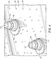
FIG. 4 is perspective view from outside a combustor chamber of an attachment feature of a combustor panel extending through a combustor shell, in accordance with various embodiments; -
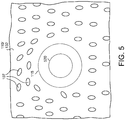
FIG. 5 is a view from within the combustor chamber of a combustor panel, in accordance with various embodiments; and -
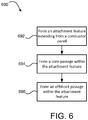
FIG. 6 is a schematic flow chart diagram of a method of manufacturing a combustor panel, in accordance with various embodiments. - The subject matter of the present disclosure is particularly pointed out and distinctly claimed in the concluding portion of the specification. A more complete understanding of the present disclosure, however, may best be obtained by referring to the detailed description and claims when considered in connection with the drawing figures, wherein like numerals denote like elements.
- The detailed description of exemplary embodiments herein makes reference to the accompanying drawings, which show exemplary embodiments by way of illustration. While these exemplary embodiments are described in sufficient detail to enable those skilled in the art to practice the disclosure, it should be understood that other embodiments may be realized and that logical changes and adaptations in design and construction may be made in accordance with this disclosure and the teachings herein without departing from the scope of the disclosure. Thus, the detailed description herein is presented for purposes of illustration only and not of limitation.
- As used herein, "aft" refers to the direction associated with the exhaust (e.g., the back end) of a gas turbine engine. As used herein, "forward" refers to the direction associated with the intake (e.g., the front end) of a gas turbine engine. A first component that is "radially outward" of a second component means that the first component is positioned at a greater distance away from the engine central longitudinal axis than the second component. A first component that is "radially inward" of a second component means that the first component is positioned closer to the engine central longitudinal axis than the second component. In the case of components that rotate circumferentially about the engine central longitudinal axis, a first component that is radially inward of a second component rotates through a circumferentially shorter path than the second component. The terminology "radially outward" and "radially inward" may also be used relative to references other than the engine central longitudinal axis. For example, a first component of a combustor that is radially inward or radially outward of a second component of a combustor is positioned relative to the central longitudinal axis of the combustor. The term "axial," as used herein, refers to a direction along or parallel to the engine central longitudinal axis.
- In various embodiments and with reference to
FIG. 1 , agas turbine engine 20 is provided.Gas turbine engine 20 may be a two-spool turbofan that generally incorporates afan section 22, acompressor section 24, acombustor section 26 and aturbine section 28. Alternative engines may include, for example, an augmentor section among other systems or features. In operation,fan section 22 can drive coolant (e.g., air) along a bypass flow-path B whilecompressor section 24 can drive coolant along a core flow-path C for compression and communication intocombustor section 26 then expansion throughturbine section 28. Although depicted as a turbofangas turbine engine 20 herein, it should be understood that the concepts described herein are not limited to use with turbofans as the teachings may be applied to other types of turbine engines including three-spool architectures. -
Gas turbine engine 20 may generally comprise alow speed spool 30 and ahigh speed spool 32 mounted for rotation about an engine central longitudinal axis A-A' relative to an enginestatic structure 36 or engine case viaseveral bearing systems 38, 38-1, and 38-2. Engine central longitudinal axis A-A' is oriented in the z direction on the provided xyz axis. It should be understood that various bearingsystems 38 at various locations may alternatively or additionally be provided, including for example, bearingsystem 38, bearing system 38-1, and bearing system 38-2. -
Low speed spool 30 may generally comprise aninner shaft 40 that interconnects afan 42, alow pressure compressor 44 and alow pressure turbine 46.Inner shaft 40 may be connected to fan 42 through a gearedarchitecture 48 that can drivefan 42 at a lower speed thanlow speed spool 30.Geared architecture 48 may comprise agear assembly 60 enclosed within agear housing 62.Gear assembly 60 couplesinner shaft 40 to a rotating fan structure.High speed spool 32 may comprise anouter shaft 50 that interconnects ahigh pressure compressor 52 andhigh pressure turbine 54. - A
combustor 56 may be located betweenhigh pressure compressor 52 andhigh pressure turbine 54. Thecombustor section 26 may have an annular wall assembly having inner and outer shells that support respective inner and outer heat shielding liners. The heat shield liners may include a plurality of combustor panels that collectively define the annular combustion chamber of thecombustor 56. An annular cooling cavity is defined between the respective shells and combustor panels for supplying cooling air. Impingement holes are located in the shell to supply the cooling air from an outer air plenum and into the annular cooling cavity. - A
mid-turbine frame 57 of enginestatic structure 36 may be located generally betweenhigh pressure turbine 54 andlow pressure turbine 46.Mid-turbine frame 57 may support one ormore bearing systems 38 inturbine section 28.Inner shaft 40 andouter shaft 50 may be concentric and rotate via bearingsystems 38 about the engine central longitudinal axis A-A', which is collinear with their longitudinal axes. As used herein, a "high pressure" compressor or turbine experiences a higher pressure than a corresponding "low pressure" compressor or turbine. - The core airflow C may be compressed by
low pressure compressor 44 thenhigh pressure compressor 52, mixed and burned with fuel incombustor 56, then expanded overhigh pressure turbine 54 andlow pressure turbine 46.Turbines low speed spool 30 andhigh speed spool 32 in response to the expansion. - In various embodiments, geared
architecture 48 may be an epicyclic gear train, such as a star gear system (sun gear in meshing engagement with a plurality of star gears supported by a carrier and in meshing engagement with a ring gear) or other gear system.Geared architecture 48 may have a gear reduction ratio of greater than about 2.3 andlow pressure turbine 46 may have a pressure ratio that is greater than about five (5). In various embodiments, the bypass ratio ofgas turbine engine 20 is greater than about ten (10:1). In various embodiments, the diameter offan 42 may be significantly larger than that of thelow pressure compressor 44, and thelow pressure turbine 46 may have a pressure ratio that is greater than about five (5:1).Low pressure turbine 46 pressure ratio may be measured prior to inlet oflow pressure turbine 46 as related to the pressure at the outlet oflow pressure turbine 46 prior to an exhaust nozzle. It should be understood, however, that the above parameters are exemplary of various embodiments of a suitable geared architecture engine and that the present disclosure contemplates other gas turbine engines including direct drive turbofans. A gas turbine engine may comprise an industrial gas turbine (IGT) or a geared aircraft engine, such as a geared turbofan, or non-geared aircraft engine, such as a turbofan, or may comprise any gas turbine engine as desired. - With reference to
FIG. 2 , an in accordance with various embodiments, one or more combustor panels 110 (e.g., thermal shields, combustor liners) may be positioned incombustor 56 to protect various features of the combustor 56 from the high temperature flames and/or combustion gases. Thecombustor 56, in various embodiments, may have acombustor chamber 102 defined by a combustorouter shell 104 and a combustorinner shell 184. Adiffuser chamber 101 is external thecombustor 56 and cooling air may be configured to flow through thediffuser chamber 101 around thecombustor 56. Thecombustor chamber 102 may form a region of mixing of core airflow C (with brief reference toFIG. 1 ) and fuel, and may direct the high-speed exhaust gases produced by the ignition of this mixture inside thecombustor 56. The combustorouter shell 104 and the combustorinner shell 184 may provide structural support to thecombustor 56 and its components. For example, a combustorouter shell 104 and a combustorinner shell 184 may comprise a substantially cylindrical or a substantially conical canister portion defining an inner area comprising thecombustor chamber 102. - As mentioned above, it may be desirable to protect the combustor
outer shell 104 and the combustorinner shell 184 from the harmful effects of high temperatures. Accordingly, one or morecombustor panels 110 may be disposed inside thecombustor chamber 102 and may provide such protection. Thecombustor panels 110 may comprise a partial cylindrical or conical surface section. An outer combustor thermal panel may be arranged radially inward of the combustorouter shell 104, for example, circumferentially about the inner surface of the combustorouter shell 104 and one or more inner combustor panels may also be arranged radially outward of the combustorinner shell 184. Thus, while the terms "radially outward" and "radially inward" are defined above as being relative to the engine central longitudinal axis A-A', the terms "outward" and "inward," without the modifier "radially," refer to positions relative to thecombustor chamber 102. That is, thecombustor shells combustor panels 110, and vice versa. Thecombustor panels 110 may comprise a variety of materials, such as metal, metal alloys, and/or ceramic matrix composites, among others - With continued reference to
FIG. 2 , thecombustor panels 110 may be mounted and/or coupled to thecombustor shell 104/184 via one or more attachment features 106. Thecombustor panels 110 may be made of any suitable heat tolerant material. In this manner, thecombustor panels 110 may be substantially resistant to thermal mechanical fatigue in order to inhibit cracking of thecombustor panels 110 and/or to inhibit liberation of portions of thecombustor panels 110. In various embodiments, thecombustor panels 110 may be made from a nickel based alloy and/or a cobalt based alloy, among others. For example, thecombustor panels 110 may be made from a high performance nickel-based super alloy. In various embodiments, thecombustor panels 110 may be made from a cobalt-nickel-chromium-tungsten alloy. - In various embodiments, and with reference to
FIG. 3 , anannular cooling cavity 117 is formed and/or defined between thecombustor shell 104 and thecombustor panel 110. As mentioned above, cooling air in thediffuser chamber 101 may enter theannular cooling cavity 117 via impingement holes 105 formed in thecombustor shell 104. That is, impingement holes 105 may extend from a diffuser-facingside 141 of thecombustor shell 104 to a combustor-facingside 142 of thecombustor shell 104 and may supply cooling air to theannular cooling cavity 117. The cooling air in theannular cooling cavity 117 may enter thecombustor chamber 102 via effusion holes 107 formed in the combustor panel. That is, effusion holes 107 may extend from a cooling surface or "cold side" 131 of the combustor panel to a combustion facing surface or "hot side" 132 of the combustor panel that is opposite thecold side 131. In various embodiments, the effusion holes 107 are generally oriented to create a protective "blanket" of air film over thehot side 132 of the combustor panel thereby protecting the combustor panel from the hot combustion gases in thecombustor chamber 102. - The one or more attachment features 106 facilitate coupling and/or mounting the
combustor panels 110 to therespective shells combustor 56. In various embodiments, theattachment feature 106 may be a boss or a stud extending from thecombustor panels 110, as described in greater detail below. The high operating temperatures and pressure ratios of the combustion gases in thecombustor section 26 may create operating environments that can damage various components of the combustor. A conventional combustor may cause hotspots to form in the vicinity of the attachment features and thus potentially shortening the operational life of the combustor because such areas of the assembly are prone to oxidation (e.g., "burnthrough") of the combustor panel. In various embodiments, and with reference to bothFIGS. 3 and5 , area 115 (which generally marks and refers to a region of the combustor panel, the combustor shell, and the volume there-between), in a conventional combustor, may lack sufficient cooling airflow. This insufficient airflow in a conventional combustor is due in part because of the lack of effusion holes and/or impingement holes inarea 115. It may be imprudent to have cooling holes inarea 115 due to concerns regarding the structural integrity of the combustor panel if effusion holes are placed too close to the attachment feature, a projected footprint of which (i.e., projected attachment feature footprint 520) is shown inFIG. 5 . Additionally, impingement holes may not be operative if positioned too close to the attachment feature, as the washer 154 (see alsoFIG. 4 ) would cover such impingement holes. Therefore, disclosed herein, according to various embodiments, is a cooling configuration for anattachment feature 106 that provides cooling airflow to theattachment feature 106 itself and cooling airflow toarea 115. - In various embodiments, and with continued reference to
FIG. 3 , acombustor panel 110 having anattachment feature 106 extending therefrom is provided. Theattachment feature 106, according to various embodiments, has a centrallongitudinal axis 125 and extends from thecold side 131 of thecombustor panel 110. Theattachment feature 106 may include abase portion 121 and atip portion 122. Thebase portion 121 of theattachment feature 106 is generally defined, according to various embodiments, as the section of theattachment feature 106 disposed between thecold side 131 of thecombustor panel 110 and the diffuser-facingside 141 of the combustor shell 140. Thetip portion 122 of theattachment feature 106 is generally defined, according to various embodiments, as the section of theattachment feature 106 disposed outward of the diffuser-facingside 141 of thecombustor shell 104. Once again, as established above, the terms "outward" and "inward," without the modifier "radially", refer to positions relative to thecombustor chamber 102. That is, thecombustor shell 104 is outward of thecombustor panel 110. - In various embodiments, the
attachment feature 106 defines acore passage 124 and one ormore offshoot passages 126. Thecore passage 124 extends from aninlet opening 123 defined on thetip portion 122 of theattachment feature 106 and extends partially through a length of theattachment feature 106. That is, thecore passage 124 terminates (i.e., has a closed, terminating end) within theattachment feature 106 and thus does not extend entirely through theattachment feature 106 or thecombustor panel 110 to thecombustor chamber 102. The closed end of thecore passage 124 may be in thetip portion 122 or thebase portion 121. Theoffshoot passage 126 extends from thecore passage 124 to anoutlet opening 127 defined on thebase portion 121 of theattachment feature 106. Said differently, the outlet opening 127 of theoffshoot passage 126 is defined on a circumference of thebase portion 121 of the attachment feature and extends to intersect thecore passage 124. Thus, thecore passage 124 and theoffshoot passage 126 collectively form a cooling airflow conduit from thediffuser chamber 101, through thetip portion 122 of theattachment feature 106, and into theannular cooling cavity 117. Accordingly, thecore passage 124 and theoffshoot passage 126 provide cooling airflow to theattachment feature 106 and provide impingement cooling to thecold side 131 of thecombustor panel 110 inarea 115. - In various embodiments, and with continued reference to
FIG. 3 , thecore passage 124 extends parallel to the centrallongitudinal axis 125. In various embodiments, thecore passage 124 is coaxial with the centrallongitudinal axis 125. In various embodiments, the offshoot passage(s) 124 may be circumferentially distributed around and may extend radially, relative to the centrallongitudinal axis 125 of theattachment feature 106, from thecore passage 124. In various embodiments, theattachment feature 106 may define a plurality ofoffshoot passages 126. For example, theattachment feature 106 may define between 2 and 5offshoot passages 126. In various embodiments, theattachment feature 106 defines 3 offshoot passages. In various embodiments, theattachment feature 106 defines 4 offshoot passages. - In various embodiments, an
angle 128 between the centrallongitudinal axis 125 and eachoffshoot passage 126 is between about 15 degrees and about 85 degrees. As used in this context only, the term "about" refers to plus or minus 5 degrees. In various embodiments, theangle 128 is between about 30 degrees and about 60 degrees. In various embodiments, theangle 128 is about 45 degrees. - In various embodiments, and with reference to
FIGS. 3 and4 , theattachment feature 106 is a cylindrical boss, such as a pin with a threaded circumference, or may be a rectangular boss, such as for receiving a clip, or may be any other apparatus whereby thecombustor panel 110 is mounted to thecombustor shell 104. Theattachment feature 106 may be integrally formed with thecombustor panel 110. In various embodiments, theattachment feature 106 comprises a threaded stud that extends throughhole 144 in thecombustor shell 104. Theattachment feature 106 may be retained in position by anut 152 disposed outward of thecombustor shell 104 and engaged onto the attachment feature and torqued so that theattachment feature 106 is preloaded with a retaining force and securely affixes thecombustor panel 110 in a substantially fixed position relative to thecombustor shell 104. In various embodiments, awasher 154 may be disposed between thenut 152 and the diffuser-facingside 141 of thecombustor shell 104. In various embodiments, thehole 144 in thecombustor shell 104 through which theattachment feature 106 extends may be oval, obround, or some other elongated shape (e.g., a slot) to provide clearance/tolerance during assembly/installation of thecombustor panel 110. Accordingly, thewasher 154 may have a corresponding elongated shape (FIG. 4 ). - In various embodiments, and with continued reference to
FIGS. 3 and4 , thecombustor panel 110 includes a plurality ofstandoffs 112 extending from thecold side 131 of thecombustor panel 110 that are circumferentially distributed around thebase portion 121 of theattachment feature 106. In various embodiments, the outlet opening 127 of the offshoot passage(s) 126 is configured to deliver impingement cooling air to an interconnected volume defined between thestandoffs 112 and theattachment feature 106. That is, the offshoot passage(s) 126 are configured for delivering cooling airflow to the portion of theannular cooling cavity 117 adjacent theattachment feature 106. In various embodiments, the outlet opening 127 of the offshoot passage(s) 126 is disposed inward of thewasher 154. In various embodiments, theoutlet opening 127 is at least partially disposed within thehole 144 defined in thecombustor shell 104. In such embodiments, thehole 144 may have a chamferedinward edge 145 or a filleted inward edge. The chamfered or filletedinward edge 145 of thehole 144 may facilitate the flow of cooling airflow exiting the outlet opening 127 (i.e., may prevent thecombustor shell 104 from obstructing all or a portion of the outlet opening 127). In various embodiments, theoutlet opening 127 is disposed inward of the combustor-facingside 142 of thecombustor shell 104. - In various embodiments, and with reference to
FIG. 6 , amethod 690 of manufacturing thecombustor panel 110 is provided. Themethod 690 may include forming theattachment feature 106 extending from thecombustor panel 110 atstep 692, forming thecore passage 124 within theattachment feature 106 atstep 694, and forming at least oneoffshoot passage 126 within theattachment feature 106 atstep 696. Themethod 690 may be performed using various manufacturing techniques. In various embodiments, atleast steps - Benefits, other advantages, and solutions to problems have been described herein with regard to specific embodiments. Furthermore, the connecting lines shown in the various figures contained herein are intended to represent exemplary functional relationships and/or physical couplings between the various elements. It should be noted that many alternative or additional functional relationships or physical connections may be present in a practical system. However, the benefits, advantages, solutions to problems, and any elements that may cause any benefit, advantage, or solution to occur or become more pronounced are not to be construed as critical, required, or essential features or elements of the disclosure.
- The scope of the disclosure is accordingly to be limited by nothing other than the appended claims, in which reference to an element in the singular is not intended to mean "one and only one" unless explicitly so stated, but rather "one or more." It is to be understood that unless specifically stated otherwise, references to "a," "an," and/or "the" may include one or more than one and that reference to an item in the singular may also include the item in the plural. All ranges and ratio limits disclosed herein may be combined.
- Moreover, where a phrase similar to "at least one of A, B, and C" is used in the claims, it is intended that the phrase be interpreted to mean that A alone may be present in an embodiment, B alone may be present in an embodiment, C alone may be present in an embodiment, or that any combination of the elements A, B and C may be present in a single embodiment; for example, A and B, A and C, B and C, or A and B and C. Different cross-hatching is used throughout the figures to denote different parts but not necessarily to denote the same or different materials.
- The steps recited in any of the method or process descriptions may be executed in any order and are not necessarily limited to the order presented. Furthermore, any reference to singular includes plural embodiments, and any reference to more than one component or step may include a singular embodiment or step. Elements and steps in the figures are illustrated for simplicity and clarity and have not necessarily been rendered according to any particular sequence. For example, steps that may be performed concurrently or in different order are illustrated in the figures to help to improve understanding of embodiments of the present disclosure.
- Any reference to attached, fixed, connected or the like may include permanent, removable, temporary, partial, full and/or any other possible attachment option. Additionally, any reference to without contact (or similar phrases) may also include reduced contact or minimal contact. Surface shading lines may be used throughout the figures to denote different parts or areas but not necessarily to denote the same or different materials. In some cases, reference coordinates may be specific to each figure.
- Systems, methods and apparatus are provided herein. In the detailed description herein, references to "one embodiment," "an embodiment," "various embodiments," etc., indicate that the embodiment described may include a particular feature, structure, or characteristic, but every embodiment may not necessarily include the particular feature, structure, or characteristic. Moreover, such phrases are not necessarily referring to the same embodiment. Further, when a particular feature, structure, or characteristic is described in connection with an embodiment, it is submitted that it is within the knowledge of one skilled in the art to affect such feature, structure, or characteristic in connection with other embodiments whether or not explicitly described. After reading the description, it will be apparent to one skilled in the relevant art(s) how to implement the disclosure in alternative embodiments.
- Furthermore, no element, component, or method step in the present disclosure is intended to be dedicated to the public regardless of whether the element, component, or method step is explicitly recited in the claims. No claim element is intended to invoke 35 U.S.C. 112(f) unless the element is expressly recited using the phrase "means for." As used herein, the terms "comprises," "comprising," or any other variation thereof, are intended to cover a non-exclusive inclusion, such that a process, method, article, or apparatus that comprises a list of elements does not include only those elements but may include other elements not expressly listed or inherent to such process, method, article, or apparatus.
Claims (15)
- A combustor panel comprising:an attachment feature having a central longitudinal axis and extending from a cold side of the combustor panel, the attachment feature comprising a tip portion and a base portion, wherein the attachment feature is configured to extend through a combustor shell such that the tip portion is disposed outward of a diffuser-facing side of the combustor shell, wherein the base portion is configured to be disposed between the cold side of the combustor panel and the diffuser-facing side of the combustor shell, the attachment feature defining:a core passage extending from an inlet opening defined on the tip portion and extending partially through the attachment feature to terminate within the attachment feature; andan offshoot passage extending from the core passage to an outlet opening defined on the base portion.
- The combustor panel of claim 1, wherein the attachment feature is integrally formed with the combustor panel.
- The combustor panel of claim 1 or 2, wherein the core passage extends parallel to the central longitudinal axis.
- The combustor panel of claim 3, wherein the core passage is coaxial with the central longitudinal axis.
- The combustor panel of claim 4, wherein the offshoot passage is one offshoot passage of a plurality of offshoot passages.
- The combustor panel of claim 5, wherein the plurality of offshoot passages are circumferentially distributed and extend radially, relative to the central longitudinal axis of the attachment feature, from the core passage.
- The combustor panel of claim 6, wherein the plurality of offshoot passages comprises a first offshoot passage, a second offshoot passage and a third offshoot passage, or
wherein the plurality of offshoot passages comprises a first offshoot passage, a second offshoot passage, a third offshoot passage, and a fourth offshoot passage. - The combustor panel of claim 6 or 7, wherein an angle between the central longitudinal axis and each offshoot passage of the plurality of offshoot passages is between about 15 degrees and about 85 degrees,
wherein, optionally, the angle is between about 30 degrees and about 60 degrees, wherein, optionally, the angle is about 45 degrees. - A gas turbine engine comprising
a combustor shell comprising a diffuser-facing side and a combustor-facing side; and
a combustor panel comprising a cold side and a hot side, the combustor panel coupled to the combustor shell via an attachment feature integrally formed with and extending from the cold side of the combustor panel, the attachment feature having a central longitudinal axis and extending through a hole in the combustor shell, wherein an annular cooling cavity is defined between the combustor shell and the combustor panel, wherein a cooling airflow conduit extends through the attachment feature and comprises an inlet opening for receiving cooling air from a diffuser chamber that is at least partially defined by the diffuser-facing side of the combustor shell and an outlet opening for delivering the cooling air to the annular cooling cavity adjacent the attachment feature. - The gas turbine engine of claim 9, wherein a tip portion of the attachment feature is disposed outward of the hole in the combustor shell and a base portion of the attachment feature is disposed between the cold side of the combustor panel and the diffuser-facing side of the combustor shell, wherein the cooling airflow conduit comprises:a core passag98e extending from the inlet opening defined on the tip portion and extending partially through the attachment feature to terminate within the attachment feature; andan offshoot passage extending from the core passage to the outlet opening defined on the base portion.
- The gas turbine engine of claim 10, wherein the tip portion of the attachment feature comprises a threaded circumference for engaging a nut, wherein a washer is disposed between the nut and the diffuser-facing side of the combustor shell,
wherein, optionally, the outlet opening of the offshoot passage is disposed inward of the washer. - The gas turbine engine of claim 10 or 11, wherein the outlet opening of the offshoot passage is at least partially disposed within the hole in the combustor shell,
wherein, optionally, the hole in the combustor shell comprises a chamfered inward edge or a filleted inward edge. - The gas turbine engine of claim 10, 11 or 12, wherein the combustor panel comprises a plurality of standoffs extending from the cold side of the combustor panel and circumferentially disposed around the base portion of the attachment feature, wherein the outlet opening of the offshoot passage is configured to deliver impingement cooling air to an interconnected volume defined between the standoffs and the attachment feature.
- A method of manufacturing a combustor panel, the method comprising:forming an attachment feature extending from a cold side of the combustor panel;forming a core passage extending from a tip portion of the attachment feature, partially through a length of the attachment feature, and terminating within the attachment feature; andforming an offshoot passage extending from the core passage to an outlet opening defined on a base portion of the attachment feature.
- The method of claim 14, wherein forming the core passage and forming the offshoot passage are performed via at least one of electrical discharge machining, additive manufacturing, or core casting.
Applications Claiming Priority (1)
| Application Number | Priority Date | Filing Date | Title |
|---|---|---|---|
| US15/699,838 US10619857B2 (en) | 2017-09-08 | 2017-09-08 | Cooling configuration for combustor attachment feature |
Publications (2)
| Publication Number | Publication Date |
|---|---|
| EP3453965A1 true EP3453965A1 (en) | 2019-03-13 |
| EP3453965B1 EP3453965B1 (en) | 2021-10-27 |
Family
ID=63517690
Family Applications (1)
| Application Number | Title | Priority Date | Filing Date |
|---|---|---|---|
| EP18192574.4A Active EP3453965B1 (en) | 2017-09-08 | 2018-09-04 | Cooling configuration for combustor attachment feature |
Country Status (2)
| Country | Link |
|---|---|
| US (1) | US10619857B2 (en) |
| EP (1) | EP3453965B1 (en) |
Families Citing this family (6)
| Publication number | Priority date | Publication date | Assignee | Title |
|---|---|---|---|---|
| US10428676B2 (en) * | 2017-06-13 | 2019-10-01 | Rolls-Royce Corporation | Tip clearance control with variable speed blower |
| US11359810B2 (en) * | 2017-12-22 | 2022-06-14 | Raytheon Technologies Corporation | Apparatus and method for mitigating particulate accumulation on a component of a gas turbine |
| US11209162B2 (en) * | 2019-01-04 | 2021-12-28 | Raytheon Technologies Corporation | Combustor panel stud cooling effusion through heat transfer augmentors |
| FR3128007A1 (en) * | 2021-10-12 | 2023-04-14 | Safran Aircraft Engines | turbomachine combustion chamber |
| CN116772238A (en) | 2022-03-08 | 2023-09-19 | 通用电气公司 | Dome-deflector joint cooling arrangement |
| CN116928697A (en) | 2022-04-06 | 2023-10-24 | 通用电气公司 | Burner deflector assembly |
Citations (5)
| Publication number | Priority date | Publication date | Assignee | Title |
|---|---|---|---|---|
| EP1389690A1 (en) * | 2002-08-16 | 2004-02-18 | Siemens Aktiengesellschaft | Screw interiorly cooled |
| US20150096302A1 (en) * | 2013-10-08 | 2015-04-09 | Pratt & Whitney Canada Corp. | Combustor heat-shield cooling via integrated channel |
| US20150260400A1 (en) * | 2014-03-11 | 2015-09-17 | Rolls-Royce Deutschland Ltd & Co Kg | Combustion chamber shingle of a gas turbine |
| US20160273770A1 (en) * | 2013-11-05 | 2016-09-22 | United Technologies Corporation | Cooled combustor floatwall panel |
| US20160313005A1 (en) * | 2015-04-23 | 2016-10-27 | United Technologies Corporation | Additive manufactured combustor heat shield with cooled attachment stud |
Family Cites Families (30)
| Publication number | Priority date | Publication date | Assignee | Title |
|---|---|---|---|---|
| US4423000A (en) | 1980-10-17 | 1983-12-27 | Syoichi Teraoka | Method for molding hollow plastic articles |
| US4422300A (en) * | 1981-12-14 | 1983-12-27 | United Technologies Corporation | Prestressed combustor liner for gas turbine engine |
| US4749298A (en) | 1987-04-30 | 1988-06-07 | United Technologies Corporation | Temperature resistant fastener arrangement |
| US4820097A (en) | 1988-03-18 | 1989-04-11 | United Technologies Corporation | Fastener with airflow opening |
| US5019079A (en) | 1989-11-20 | 1991-05-28 | Zimmer, Inc. | Bone screw |
| GB2356041A (en) | 1999-11-05 | 2001-05-09 | Rolls Royce Plc | Wall element for combustion apparatus |
| GB2380236B (en) | 2001-09-29 | 2005-01-19 | Rolls Royce Plc | A wall structure for a combustion chamber of a gas turbine engine |
| US7967562B2 (en) | 2006-06-06 | 2011-06-28 | United Technologies Corporation | Ceramic matrix composite capped bolt attachment |
| US7681398B2 (en) | 2006-11-17 | 2010-03-23 | Pratt & Whitney Canada Corp. | Combustor liner and heat shield assembly |
| US20100263386A1 (en) | 2009-04-16 | 2010-10-21 | General Electric Company | Turbine engine having a liner |
| US8800298B2 (en) | 2009-07-17 | 2014-08-12 | United Technologies Corporation | Washer with cooling passage for a turbine engine combustor |
| DE102010027204A1 (en) | 2010-07-06 | 2012-01-12 | Newfrey Llc | Nut, mounting arrangement and mounting method |
| CN202418176U (en) | 2011-12-22 | 2012-09-05 | 中航商用航空发动机有限责任公司 | Bolt |
| EP2711630A1 (en) * | 2012-09-21 | 2014-03-26 | Siemens Aktiengesellschaft | Device for cooling a support structure of a heat shield and heat shield |
| US10107497B2 (en) | 2012-10-04 | 2018-10-23 | United Technologies Corporation | Gas turbine engine combustor liner |
| DE102012022199A1 (en) | 2012-11-13 | 2014-05-28 | Rolls-Royce Deutschland Ltd & Co Kg | Combustor shingle of a gas turbine |
| GB201222311D0 (en) * | 2012-12-12 | 2013-01-23 | Rolls Royce Plc | A combusiton chamber |
| EP3027869B1 (en) | 2013-08-01 | 2018-05-02 | United Technologies Corporation | Attachment scheme for a bulkhead panel |
| US10240790B2 (en) | 2013-11-04 | 2019-03-26 | United Technologies Corporation | Turbine engine combustor heat shield with multi-height rails |
| DE102013222932A1 (en) * | 2013-11-11 | 2015-05-28 | Rolls-Royce Deutschland Ltd & Co Kg | Gas turbine combustion chamber with shingle for carrying out a spark plug |
| DE102013223258A1 (en) | 2013-11-14 | 2015-06-03 | Rolls-Royce Deutschland Ltd & Co Kg | Combustion heat shield element of a gas turbine |
| WO2015122950A2 (en) | 2013-11-21 | 2015-08-20 | United Technologies Corporation | Turbine engine multi-walled structure with internal cooling element(s) |
| WO2015147938A2 (en) | 2014-01-03 | 2015-10-01 | United Technologies Corporation | A cooled grommet for a combustor wall assembly |
| US9625152B2 (en) | 2014-06-03 | 2017-04-18 | Pratt & Whitney Canada Corp. | Combustor heat shield for a gas turbine engine |
| GB201418042D0 (en) | 2014-10-13 | 2014-11-26 | Rolls Royce Plc | A liner element for a combustor, and a related method |
| US10935240B2 (en) | 2015-04-23 | 2021-03-02 | Raytheon Technologies Corporation | Additive manufactured combustor heat shield |
| GB201600760D0 (en) | 2016-01-15 | 2016-03-02 | Rolls Royce Plc | A combustion chamber arrangement |
| US10533747B2 (en) * | 2017-03-30 | 2020-01-14 | General Electric Company | Additively manufactured mechanical fastener with cooling fluid passageways |
| US20180292089A1 (en) | 2017-04-05 | 2018-10-11 | United Technologies Corporation | Combustor attachment cooling |
| US10247419B2 (en) | 2017-08-01 | 2019-04-02 | United Technologies Corporation | Combustor liner panel with a multiple of heat transfer ribs for a gas turbine engine combustor |
-
2017
- 2017-09-08 US US15/699,838 patent/US10619857B2/en active Active
-
2018
- 2018-09-04 EP EP18192574.4A patent/EP3453965B1/en active Active
Patent Citations (5)
| Publication number | Priority date | Publication date | Assignee | Title |
|---|---|---|---|---|
| EP1389690A1 (en) * | 2002-08-16 | 2004-02-18 | Siemens Aktiengesellschaft | Screw interiorly cooled |
| US20150096302A1 (en) * | 2013-10-08 | 2015-04-09 | Pratt & Whitney Canada Corp. | Combustor heat-shield cooling via integrated channel |
| US20160273770A1 (en) * | 2013-11-05 | 2016-09-22 | United Technologies Corporation | Cooled combustor floatwall panel |
| US20150260400A1 (en) * | 2014-03-11 | 2015-09-17 | Rolls-Royce Deutschland Ltd & Co Kg | Combustion chamber shingle of a gas turbine |
| US20160313005A1 (en) * | 2015-04-23 | 2016-10-27 | United Technologies Corporation | Additive manufactured combustor heat shield with cooled attachment stud |
Also Published As
| Publication number | Publication date |
|---|---|
| US10619857B2 (en) | 2020-04-14 |
| US20190078789A1 (en) | 2019-03-14 |
| EP3453965B1 (en) | 2021-10-27 |
Similar Documents
| Publication | Publication Date | Title |
|---|---|---|
| US10473331B2 (en) | Combustor panel endrail interface | |
| EP3453965B1 (en) | Cooling configuration for combustor attachment feature | |
| EP3404330B1 (en) | Redundant endrail for combustor panel | |
| EP3330612B1 (en) | Systems and methods for combustor panel | |
| US10837635B2 (en) | Fuel swirler with anti-rotation features | |
| EP3453967B1 (en) | Combustor panel with cooling configuration for combustor panel attachment feature | |
| EP3587928B1 (en) | Combustor shell | |
| EP3453968B1 (en) | Cooling configurations for combustor attachment features | |
| EP3431874A1 (en) | Combustor panel standoffs with cooling holes | |
| EP3453966B1 (en) | Combustor panel | |
| US11175041B2 (en) | Systems and methods for combustor panel | |
| EP3382278A1 (en) | Combustor panel heat transfer pins with varying geometric specifications and method of manufacturing the panel | |
| EP3453969B1 (en) | Combustor panel with attachment feature |
Legal Events
| Date | Code | Title | Description |
|---|---|---|---|
| PUAI | Public reference made under article 153(3) epc to a published international application that has entered the european phase |
Free format text: ORIGINAL CODE: 0009012 |
|
| STAA | Information on the status of an ep patent application or granted ep patent |
Free format text: STATUS: THE APPLICATION HAS BEEN PUBLISHED |
|
| AK | Designated contracting states |
Kind code of ref document: A1 Designated state(s): AL AT BE BG CH CY CZ DE DK EE ES FI FR GB GR HR HU IE IS IT LI LT LU LV MC MK MT NL NO PL PT RO RS SE SI SK SM TR |
|
| AX | Request for extension of the european patent |
Extension state: BA ME |
|
| STAA | Information on the status of an ep patent application or granted ep patent |
Free format text: STATUS: REQUEST FOR EXAMINATION WAS MADE |
|
| 17P | Request for examination filed |
Effective date: 20190912 |
|
| RBV | Designated contracting states (corrected) |
Designated state(s): AL AT BE BG CH CY CZ DE DK EE ES FI FR GB GR HR HU IE IS IT LI LT LU LV MC MK MT NL NO PL PT RO RS SE SI SK SM TR |
|
| RAP1 | Party data changed (applicant data changed or rights of an application transferred) |
Owner name: RAYTHEON TECHNOLOGIES CORPORATION |
|
| GRAP | Despatch of communication of intention to grant a patent |
Free format text: ORIGINAL CODE: EPIDOSNIGR1 |
|
| STAA | Information on the status of an ep patent application or granted ep patent |
Free format text: STATUS: GRANT OF PATENT IS INTENDED |
|
| INTG | Intention to grant announced |
Effective date: 20210507 |
|
| GRAS | Grant fee paid |
Free format text: ORIGINAL CODE: EPIDOSNIGR3 |
|
| GRAA | (expected) grant |
Free format text: ORIGINAL CODE: 0009210 |
|
| STAA | Information on the status of an ep patent application or granted ep patent |
Free format text: STATUS: THE PATENT HAS BEEN GRANTED |
|
| AK | Designated contracting states |
Kind code of ref document: B1 Designated state(s): AL AT BE BG CH CY CZ DE DK EE ES FI FR GB GR HR HU IE IS IT LI LT LU LV MC MK MT NL NO PL PT RO RS SE SI SK SM TR |
|
| REG | Reference to a national code |
Ref country code: GB Ref legal event code: FG4D |
|
| REG | Reference to a national code |
Ref country code: CH Ref legal event code: EP |
|
| REG | Reference to a national code |
Ref country code: DE Ref legal event code: R096 Ref document number: 602018025584 Country of ref document: DE |
|
| REG | Reference to a national code |
Ref country code: AT Ref legal event code: REF Ref document number: 1442117 Country of ref document: AT Kind code of ref document: T Effective date: 20211115 |
|
| REG | Reference to a national code |
Ref country code: IE Ref legal event code: FG4D |
|
| REG | Reference to a national code |
Ref country code: LT Ref legal event code: MG9D |
|
| REG | Reference to a national code |
Ref country code: NL Ref legal event code: MP Effective date: 20211027 |
|
| REG | Reference to a national code |
Ref country code: AT Ref legal event code: MK05 Ref document number: 1442117 Country of ref document: AT Kind code of ref document: T Effective date: 20211027 |
|
| PG25 | Lapsed in a contracting state [announced via postgrant information from national office to epo] |
Ref country code: RS Free format text: LAPSE BECAUSE OF FAILURE TO SUBMIT A TRANSLATION OF THE DESCRIPTION OR TO PAY THE FEE WITHIN THE PRESCRIBED TIME-LIMIT Effective date: 20211027 Ref country code: LT Free format text: LAPSE BECAUSE OF FAILURE TO SUBMIT A TRANSLATION OF THE DESCRIPTION OR TO PAY THE FEE WITHIN THE PRESCRIBED TIME-LIMIT Effective date: 20211027 Ref country code: FI Free format text: LAPSE BECAUSE OF FAILURE TO SUBMIT A TRANSLATION OF THE DESCRIPTION OR TO PAY THE FEE WITHIN THE PRESCRIBED TIME-LIMIT Effective date: 20211027 Ref country code: BG Free format text: LAPSE BECAUSE OF FAILURE TO SUBMIT A TRANSLATION OF THE DESCRIPTION OR TO PAY THE FEE WITHIN THE PRESCRIBED TIME-LIMIT Effective date: 20220127 Ref country code: AT Free format text: LAPSE BECAUSE OF FAILURE TO SUBMIT A TRANSLATION OF THE DESCRIPTION OR TO PAY THE FEE WITHIN THE PRESCRIBED TIME-LIMIT Effective date: 20211027 |
|
| PG25 | Lapsed in a contracting state [announced via postgrant information from national office to epo] |
Ref country code: IS Free format text: LAPSE BECAUSE OF FAILURE TO SUBMIT A TRANSLATION OF THE DESCRIPTION OR TO PAY THE FEE WITHIN THE PRESCRIBED TIME-LIMIT Effective date: 20220227 Ref country code: SE Free format text: LAPSE BECAUSE OF FAILURE TO SUBMIT A TRANSLATION OF THE DESCRIPTION OR TO PAY THE FEE WITHIN THE PRESCRIBED TIME-LIMIT Effective date: 20211027 Ref country code: PT Free format text: LAPSE BECAUSE OF FAILURE TO SUBMIT A TRANSLATION OF THE DESCRIPTION OR TO PAY THE FEE WITHIN THE PRESCRIBED TIME-LIMIT Effective date: 20220228 Ref country code: PL Free format text: LAPSE BECAUSE OF FAILURE TO SUBMIT A TRANSLATION OF THE DESCRIPTION OR TO PAY THE FEE WITHIN THE PRESCRIBED TIME-LIMIT Effective date: 20211027 Ref country code: NO Free format text: LAPSE BECAUSE OF FAILURE TO SUBMIT A TRANSLATION OF THE DESCRIPTION OR TO PAY THE FEE WITHIN THE PRESCRIBED TIME-LIMIT Effective date: 20220127 Ref country code: NL Free format text: LAPSE BECAUSE OF FAILURE TO SUBMIT A TRANSLATION OF THE DESCRIPTION OR TO PAY THE FEE WITHIN THE PRESCRIBED TIME-LIMIT Effective date: 20211027 Ref country code: LV Free format text: LAPSE BECAUSE OF FAILURE TO SUBMIT A TRANSLATION OF THE DESCRIPTION OR TO PAY THE FEE WITHIN THE PRESCRIBED TIME-LIMIT Effective date: 20211027 Ref country code: HR Free format text: LAPSE BECAUSE OF FAILURE TO SUBMIT A TRANSLATION OF THE DESCRIPTION OR TO PAY THE FEE WITHIN THE PRESCRIBED TIME-LIMIT Effective date: 20211027 Ref country code: GR Free format text: LAPSE BECAUSE OF FAILURE TO SUBMIT A TRANSLATION OF THE DESCRIPTION OR TO PAY THE FEE WITHIN THE PRESCRIBED TIME-LIMIT Effective date: 20220128 Ref country code: ES Free format text: LAPSE BECAUSE OF FAILURE TO SUBMIT A TRANSLATION OF THE DESCRIPTION OR TO PAY THE FEE WITHIN THE PRESCRIBED TIME-LIMIT Effective date: 20211027 |
|
| REG | Reference to a national code |
Ref country code: DE Ref legal event code: R097 Ref document number: 602018025584 Country of ref document: DE |
|
| PG25 | Lapsed in a contracting state [announced via postgrant information from national office to epo] |
Ref country code: SM Free format text: LAPSE BECAUSE OF FAILURE TO SUBMIT A TRANSLATION OF THE DESCRIPTION OR TO PAY THE FEE WITHIN THE PRESCRIBED TIME-LIMIT Effective date: 20211027 Ref country code: SK Free format text: LAPSE BECAUSE OF FAILURE TO SUBMIT A TRANSLATION OF THE DESCRIPTION OR TO PAY THE FEE WITHIN THE PRESCRIBED TIME-LIMIT Effective date: 20211027 Ref country code: RO Free format text: LAPSE BECAUSE OF FAILURE TO SUBMIT A TRANSLATION OF THE DESCRIPTION OR TO PAY THE FEE WITHIN THE PRESCRIBED TIME-LIMIT Effective date: 20211027 Ref country code: EE Free format text: LAPSE BECAUSE OF FAILURE TO SUBMIT A TRANSLATION OF THE DESCRIPTION OR TO PAY THE FEE WITHIN THE PRESCRIBED TIME-LIMIT Effective date: 20211027 Ref country code: DK Free format text: LAPSE BECAUSE OF FAILURE TO SUBMIT A TRANSLATION OF THE DESCRIPTION OR TO PAY THE FEE WITHIN THE PRESCRIBED TIME-LIMIT Effective date: 20211027 Ref country code: CZ Free format text: LAPSE BECAUSE OF FAILURE TO SUBMIT A TRANSLATION OF THE DESCRIPTION OR TO PAY THE FEE WITHIN THE PRESCRIBED TIME-LIMIT Effective date: 20211027 |
|
| PLBE | No opposition filed within time limit |
Free format text: ORIGINAL CODE: 0009261 |
|
| STAA | Information on the status of an ep patent application or granted ep patent |
Free format text: STATUS: NO OPPOSITION FILED WITHIN TIME LIMIT |
|
| 26N | No opposition filed |
Effective date: 20220728 |
|
| PG25 | Lapsed in a contracting state [announced via postgrant information from national office to epo] |
Ref country code: AL Free format text: LAPSE BECAUSE OF FAILURE TO SUBMIT A TRANSLATION OF THE DESCRIPTION OR TO PAY THE FEE WITHIN THE PRESCRIBED TIME-LIMIT Effective date: 20211027 |
|
| PG25 | Lapsed in a contracting state [announced via postgrant information from national office to epo] |
Ref country code: SI Free format text: LAPSE BECAUSE OF FAILURE TO SUBMIT A TRANSLATION OF THE DESCRIPTION OR TO PAY THE FEE WITHIN THE PRESCRIBED TIME-LIMIT Effective date: 20211027 |
|
| PG25 | Lapsed in a contracting state [announced via postgrant information from national office to epo] |
Ref country code: MC Free format text: LAPSE BECAUSE OF FAILURE TO SUBMIT A TRANSLATION OF THE DESCRIPTION OR TO PAY THE FEE WITHIN THE PRESCRIBED TIME-LIMIT Effective date: 20211027 |
|
| REG | Reference to a national code |
Ref country code: CH Ref legal event code: PL |
|
| REG | Reference to a national code |
Ref country code: BE Ref legal event code: MM Effective date: 20220930 |
|
| PG25 | Lapsed in a contracting state [announced via postgrant information from national office to epo] |
Ref country code: IT Free format text: LAPSE BECAUSE OF FAILURE TO SUBMIT A TRANSLATION OF THE DESCRIPTION OR TO PAY THE FEE WITHIN THE PRESCRIBED TIME-LIMIT Effective date: 20211027 |
|
| P01 | Opt-out of the competence of the unified patent court (upc) registered |
Effective date: 20230521 |
|
| PG25 | Lapsed in a contracting state [announced via postgrant information from national office to epo] |
Ref country code: LU Free format text: LAPSE BECAUSE OF NON-PAYMENT OF DUE FEES Effective date: 20220904 |
|
| PG25 | Lapsed in a contracting state [announced via postgrant information from national office to epo] |
Ref country code: LI Free format text: LAPSE BECAUSE OF NON-PAYMENT OF DUE FEES Effective date: 20220930 Ref country code: IE Free format text: LAPSE BECAUSE OF NON-PAYMENT OF DUE FEES Effective date: 20220904 Ref country code: CH Free format text: LAPSE BECAUSE OF NON-PAYMENT OF DUE FEES Effective date: 20220930 |
|
| PG25 | Lapsed in a contracting state [announced via postgrant information from national office to epo] |
Ref country code: BE Free format text: LAPSE BECAUSE OF NON-PAYMENT OF DUE FEES Effective date: 20220930 |
|
| PGFP | Annual fee paid to national office [announced via postgrant information from national office to epo] |
Ref country code: GB Payment date: 20230823 Year of fee payment: 6 |
|
| PGFP | Annual fee paid to national office [announced via postgrant information from national office to epo] |
Ref country code: FR Payment date: 20230822 Year of fee payment: 6 Ref country code: DE Payment date: 20230822 Year of fee payment: 6 |
|
| PG25 | Lapsed in a contracting state [announced via postgrant information from national office to epo] |
Ref country code: HU Free format text: LAPSE BECAUSE OF FAILURE TO SUBMIT A TRANSLATION OF THE DESCRIPTION OR TO PAY THE FEE WITHIN THE PRESCRIBED TIME-LIMIT; INVALID AB INITIO Effective date: 20180904 |
|
| PG25 | Lapsed in a contracting state [announced via postgrant information from national office to epo] |
Ref country code: CY Free format text: LAPSE BECAUSE OF FAILURE TO SUBMIT A TRANSLATION OF THE DESCRIPTION OR TO PAY THE FEE WITHIN THE PRESCRIBED TIME-LIMIT Effective date: 20211027 |