EP3453910A1 - Vibration isolation structure - Google Patents
Vibration isolation structure Download PDFInfo
- Publication number
- EP3453910A1 EP3453910A1 EP18191944.0A EP18191944A EP3453910A1 EP 3453910 A1 EP3453910 A1 EP 3453910A1 EP 18191944 A EP18191944 A EP 18191944A EP 3453910 A1 EP3453910 A1 EP 3453910A1
- Authority
- EP
- European Patent Office
- Prior art keywords
- protruding portion
- protruding
- contact
- face
- main load
- Prior art date
- Legal status (The legal status is an assumption and is not a legal conclusion. Google has not performed a legal analysis and makes no representation as to the accuracy of the status listed.)
- Pending
Links
Images





Classifications
-
- F—MECHANICAL ENGINEERING; LIGHTING; HEATING; WEAPONS; BLASTING
- F16—ENGINEERING ELEMENTS AND UNITS; GENERAL MEASURES FOR PRODUCING AND MAINTAINING EFFECTIVE FUNCTIONING OF MACHINES OR INSTALLATIONS; THERMAL INSULATION IN GENERAL
- F16F—SPRINGS; SHOCK-ABSORBERS; MEANS FOR DAMPING VIBRATION
- F16F1/00—Springs
- F16F1/36—Springs made of rubber or other material having high internal friction, e.g. thermoplastic elastomers
- F16F1/371—Springs made of rubber or other material having high internal friction, e.g. thermoplastic elastomers characterised by inserts or auxiliary extension or exterior elements, e.g. for rigidification
-
- B—PERFORMING OPERATIONS; TRANSPORTING
- B60—VEHICLES IN GENERAL
- B60K—ARRANGEMENT OR MOUNTING OF PROPULSION UNITS OR OF TRANSMISSIONS IN VEHICLES; ARRANGEMENT OR MOUNTING OF PLURAL DIVERSE PRIME-MOVERS IN VEHICLES; AUXILIARY DRIVES FOR VEHICLES; INSTRUMENTATION OR DASHBOARDS FOR VEHICLES; ARRANGEMENTS IN CONNECTION WITH COOLING, AIR INTAKE, GAS EXHAUST OR FUEL SUPPLY OF PROPULSION UNITS IN VEHICLES
- B60K5/00—Arrangement or mounting of internal-combustion or jet-propulsion units
- B60K5/12—Arrangement of engine supports
- B60K5/1208—Resilient supports
-
- F—MECHANICAL ENGINEERING; LIGHTING; HEATING; WEAPONS; BLASTING
- F16—ENGINEERING ELEMENTS AND UNITS; GENERAL MEASURES FOR PRODUCING AND MAINTAINING EFFECTIVE FUNCTIONING OF MACHINES OR INSTALLATIONS; THERMAL INSULATION IN GENERAL
- F16F—SPRINGS; SHOCK-ABSORBERS; MEANS FOR DAMPING VIBRATION
- F16F1/00—Springs
- F16F1/36—Springs made of rubber or other material having high internal friction, e.g. thermoplastic elastomers
- F16F1/373—Springs made of rubber or other material having high internal friction, e.g. thermoplastic elastomers characterised by having a particular shape
-
- F—MECHANICAL ENGINEERING; LIGHTING; HEATING; WEAPONS; BLASTING
- F16—ENGINEERING ELEMENTS AND UNITS; GENERAL MEASURES FOR PRODUCING AND MAINTAINING EFFECTIVE FUNCTIONING OF MACHINES OR INSTALLATIONS; THERMAL INSULATION IN GENERAL
- F16F—SPRINGS; SHOCK-ABSORBERS; MEANS FOR DAMPING VIBRATION
- F16F13/00—Units comprising springs of the non-fluid type as well as vibration-dampers, shock-absorbers, or fluid springs
- F16F13/04—Units comprising springs of the non-fluid type as well as vibration-dampers, shock-absorbers, or fluid springs comprising both a plastics spring and a damper, e.g. a friction damper
- F16F13/06—Units comprising springs of the non-fluid type as well as vibration-dampers, shock-absorbers, or fluid springs comprising both a plastics spring and a damper, e.g. a friction damper the damper being a fluid damper, e.g. the plastics spring not forming a part of the wall of the fluid chamber of the damper
- F16F13/08—Units comprising springs of the non-fluid type as well as vibration-dampers, shock-absorbers, or fluid springs comprising both a plastics spring and a damper, e.g. a friction damper the damper being a fluid damper, e.g. the plastics spring not forming a part of the wall of the fluid chamber of the damper the plastics spring forming at least a part of the wall of the fluid chamber of the damper
- F16F13/10—Units comprising springs of the non-fluid type as well as vibration-dampers, shock-absorbers, or fluid springs comprising both a plastics spring and a damper, e.g. a friction damper the damper being a fluid damper, e.g. the plastics spring not forming a part of the wall of the fluid chamber of the damper the plastics spring forming at least a part of the wall of the fluid chamber of the damper the wall being at least in part formed by a flexible membrane or the like
- F16F13/101—Units comprising springs of the non-fluid type as well as vibration-dampers, shock-absorbers, or fluid springs comprising both a plastics spring and a damper, e.g. a friction damper the damper being a fluid damper, e.g. the plastics spring not forming a part of the wall of the fluid chamber of the damper the plastics spring forming at least a part of the wall of the fluid chamber of the damper the wall being at least in part formed by a flexible membrane or the like characterised by buffering features or stoppers
-
- F—MECHANICAL ENGINEERING; LIGHTING; HEATING; WEAPONS; BLASTING
- F16—ENGINEERING ELEMENTS AND UNITS; GENERAL MEASURES FOR PRODUCING AND MAINTAINING EFFECTIVE FUNCTIONING OF MACHINES OR INSTALLATIONS; THERMAL INSULATION IN GENERAL
- F16F—SPRINGS; SHOCK-ABSORBERS; MEANS FOR DAMPING VIBRATION
- F16F13/00—Units comprising springs of the non-fluid type as well as vibration-dampers, shock-absorbers, or fluid springs
- F16F13/04—Units comprising springs of the non-fluid type as well as vibration-dampers, shock-absorbers, or fluid springs comprising both a plastics spring and a damper, e.g. a friction damper
- F16F13/06—Units comprising springs of the non-fluid type as well as vibration-dampers, shock-absorbers, or fluid springs comprising both a plastics spring and a damper, e.g. a friction damper the damper being a fluid damper, e.g. the plastics spring not forming a part of the wall of the fluid chamber of the damper
- F16F13/08—Units comprising springs of the non-fluid type as well as vibration-dampers, shock-absorbers, or fluid springs comprising both a plastics spring and a damper, e.g. a friction damper the damper being a fluid damper, e.g. the plastics spring not forming a part of the wall of the fluid chamber of the damper the plastics spring forming at least a part of the wall of the fluid chamber of the damper
- F16F13/10—Units comprising springs of the non-fluid type as well as vibration-dampers, shock-absorbers, or fluid springs comprising both a plastics spring and a damper, e.g. a friction damper the damper being a fluid damper, e.g. the plastics spring not forming a part of the wall of the fluid chamber of the damper the plastics spring forming at least a part of the wall of the fluid chamber of the damper the wall being at least in part formed by a flexible membrane or the like
- F16F13/108—Units comprising springs of the non-fluid type as well as vibration-dampers, shock-absorbers, or fluid springs comprising both a plastics spring and a damper, e.g. a friction damper the damper being a fluid damper, e.g. the plastics spring not forming a part of the wall of the fluid chamber of the damper the plastics spring forming at least a part of the wall of the fluid chamber of the damper the wall being at least in part formed by a flexible membrane or the like characterised by features of plastics springs, e.g. attachment arrangements
-
- F—MECHANICAL ENGINEERING; LIGHTING; HEATING; WEAPONS; BLASTING
- F16—ENGINEERING ELEMENTS AND UNITS; GENERAL MEASURES FOR PRODUCING AND MAINTAINING EFFECTIVE FUNCTIONING OF MACHINES OR INSTALLATIONS; THERMAL INSULATION IN GENERAL
- F16F—SPRINGS; SHOCK-ABSORBERS; MEANS FOR DAMPING VIBRATION
- F16F1/00—Springs
- F16F1/36—Springs made of rubber or other material having high internal friction, e.g. thermoplastic elastomers
- F16F1/373—Springs made of rubber or other material having high internal friction, e.g. thermoplastic elastomers characterised by having a particular shape
- F16F1/376—Springs made of rubber or other material having high internal friction, e.g. thermoplastic elastomers characterised by having a particular shape having projections, studs, serrations or the like on at least one surface
-
- F—MECHANICAL ENGINEERING; LIGHTING; HEATING; WEAPONS; BLASTING
- F16—ENGINEERING ELEMENTS AND UNITS; GENERAL MEASURES FOR PRODUCING AND MAINTAINING EFFECTIVE FUNCTIONING OF MACHINES OR INSTALLATIONS; THERMAL INSULATION IN GENERAL
- F16F—SPRINGS; SHOCK-ABSORBERS; MEANS FOR DAMPING VIBRATION
- F16F2224/00—Materials; Material properties
- F16F2224/02—Materials; Material properties solids
- F16F2224/025—Elastomers
-
- F—MECHANICAL ENGINEERING; LIGHTING; HEATING; WEAPONS; BLASTING
- F16—ENGINEERING ELEMENTS AND UNITS; GENERAL MEASURES FOR PRODUCING AND MAINTAINING EFFECTIVE FUNCTIONING OF MACHINES OR INSTALLATIONS; THERMAL INSULATION IN GENERAL
- F16F—SPRINGS; SHOCK-ABSORBERS; MEANS FOR DAMPING VIBRATION
- F16F2230/00—Purpose; Design features
- F16F2230/0052—Physically guiding or influencing
- F16F2230/007—Physically guiding or influencing with, or used as an end stop or buffer; Limiting excessive axial separation
Definitions
- the present disclosure relates to a vibration isolation structure.
- An example of a typical vibration isolation structure of this type includes a liquid-filled type vibration isolation device including a main spring portion in which an attachment metal fitting (a second attachment member) attached to a vehicle body side (a vibration receiving side) and a cylindrical body are connected together by a rubber elastic body, and an engine bracket in which a substantially cylindrical casing portion (a first attachment member) having a through hole is integrated with an attachment portion for attaching the casing portion to an engine side (a vibration origin side). Then, the cylindrical body is press-fitted into the through hole to form a liquid chamber which includes a wall portion partially comprised of the rubber elastic body and an inner peripheral surface of the casing portion, and of which the volume is variable.
- the liquid-filled type vibration isolation device of this type might include the casing portion having a stopper rubber (a stopper part). Then, for example, when a large driving reaction force acts at the time of a rapid acceleration of the vehicle and then the engine or the like is forced to be vibrated, the stopper rubber comes into contact with a member (a contact member) on the vehicle body side to restrict the deformation of the rubber elastic body in the longitudinal direction (the main load input direction) of the vehicle.
- Japanese Patent No. 5610972 paragraph [0055] and FIG. 12(a) discloses a liquid-filled vibration isolation device in which a rubber elastic body and a stopper rubber are simultaneously molded on an engine bracket.
- the stopper portion in the contact state is required to have a small dynamic spring constant in the vertical direction.
- the stopper rubber has a deformable thick shape so as to exhibit soft spring characteristics.
- the rubber elastic body considerably deforms, and the displacement of an engine cannot be reduced.
- the present disclosure is directed to a vibration isolation structure including a first attachment member attached to a vibration origin side; a second attachment member attached to a vibration receiving side; a rubber elastic body provided between the first attachment member and the second attachment member; a stopper portion made of rubber, provided on an end face of the first attachment member closer to an outside in a main load input direction, and restricting deformation of the rubber elastic body in the main load input direction; and a contact member provided on the vibration receiving side and having a contact surface which faces the stopper portion in the main load input direction and which the stopper portion comes into contact with at a time of input of a load in the main load input direction.
- the stopper portion includes a first protruding portion protruding from the end face of the first attachment portion closer to the outside in the main load input direction toward the outside in the main load input direction, and a second protruding portion protruding from the end face of the first attachment portion closer to the outside in the main load input direction toward the outside in the main load input direction, being spaced apart from the first protruding portion so as to be in a non-contact state with the first protruding portion, being thinner than the first protruding portion in the main load input direction, and having a protruding end in which a distance between the protruding end and the contact surface is longer in the main load input direction than a distance between a protruding end of the first protruding portion and the contact surface.
- the non-contact state between the first protruding portion and the second protruding portion is maintained at least until the second protruding portion comes into contact with the contact surface.
- the distance between the protruding end of the first protruding portion and the contact surface of the contact member is shorter in the main load input direction than the distance between the protruding end of the second protruding portion and the contact surface in the main load input direction.
- the first protruding portion is thicker than the second protruding portion in the main load input direction.
- the first protruding portion has a rubber volume and exhibits soft spring characteristics. Accordingly, the first protruding portion is considerably deformed. Even if the first protruding portion is deformed by coming into contact with the contact surface of the contact member at a time of input of a load in the main load input direction, the non-contact state between the first protruding portion and the second protruding portion is maintained at least until the second protruding portion comes into contact with the contact surface. Thus, the deformation of the first protruding portion continues. Accordingly, a stopper portion being in contact with the contact member can have a small dynamic spring constant in a direction orthogonal to the main load input direction.
- the second protruding portion also comes into contact with the contact surface of the contact member.
- the second protruding portion is thinner than the first protruding portion in the main load input direction.
- the second protruding portion does not have a rubber volume and exhibits hard spring characteristics. Accordingly, even when a heavy load is input in the main input load direction, the second protruding portion, and hence the rubber elastic body, do not considerably deform, and the displacement of the vibration origin can be reduced.
- the stopper portion being in contact with the contact member has a small dynamic spring constant in a direction orthogonal to the main load input direction, whereas, even when a heavy load is input in the main load input direction, the rubber elastic body does not considerably deform, and the displacement of the vibration origin can be reduced.
- the non-contact state between the first protruding portion and the second protruding portion is maintained at all times.
- the non-contact state between the first protruding portion and the second protruding portion is maintained at all times.
- the first protruding portion does not deform so as to escape in a direction orthogonal to the main load input direction.
- the stopper portion exhibits hard spring characteristics. Accordingly, even when a heavy load is input in the main load input direction, the displacement of the vibration origin can be reliably reduced.
- the end face, of the first attachment member closer to the outside in the main load input direction, on which the stopper portion is formed includes a first end face on which the first protruding portion is formed, and a second end face which is located in an outer side with respect to the main load input direction than the first end face, and on which the second protruding portion is formed.
- the first end face on which the first protruding portion is formed is located in an inner side with respect to the main load input direction than the second end face on which the second protruding portion is formed.
- the thickness in the main load input direction, and hence the rubber volume, of the first protruding portion are maintained, whereas the protruding end of the first protruding portion can be located in an inner side with respect to the main load input direction, compared with the case in which the first end face is set in substantially the same position as that of the second end face.
- the space saving can be achieved while keeping a state in which the first protruding portion exhibits soft spring characteristics.
- the contact surface is a plane extending in a direction orthogonal to the main load input direction.
- the contact surface of the contact member is a plane extending in a direction orthogonal to the main load input direction.
- the configuration of the contact surface can be simplified.
- the contact member includes a member provided on the vibration receiving side and including a formation surface facing the stopper portion in the main load input direction, and a stopper rubber formed on the formation surface. It is also preferable that the stopper rubber includes a protruding end face which serves as the contact surface.
- the contact member includes the member provided on the vibration receiving side and including the formation surface facing the stopper portion in the main load input direction, and the stopper rubber formed on the formation surface.
- the thickness in the main load input direction, and hence the rubber volume, of the stopper portion can be made smaller compared with the case in which the contact member does not include the stopper rubber.
- the durability of the stopper portion (in particular, the first protruding portion) can be improved.
- the vibration origin side is an engine side
- the vibration receiving side is a vehicle body side
- the main load input direction is a longitudinal direction of a vehicle
- the stopper portion is provided on the end face of the first attachment member closer to a rear of the vehicle.
- the stopper portion being in contact with the contact member can have a small dynamic spring constant in the vertical direction.
- a muffled sound can be restricted which is generated, for example, when gear noise vibrations from the engine in the vertical direction is transmitted to the vehicle body in a state in which the stopper portion is in contact with the contact member at the time of rapid acceleration of the vehicle.
- a stopper portion being in contact with a contact member has a small dynamic spring constant in a direction orthogonal to a main load input direction, whereas, even when a heavy load is input in the main load input direction, the rubber elastic body does not considerably deform, and the displacement of the vibration origin can be reduced.
- FIGS. 1 to 4 illustrate a vibration isolation structure of this embodiment.
- This vibration isolation structure V is configured by fixing a liquid-filled type vibration isolation device 1 to an attachment bracket 21 (an attachment member, a member on the vibration receiving side).
- This liquid-filled type vibration isolation device 1 includes: an engine bracket 3 having a hollow portion 11 and attached on a power plant (not shown) (on the vibration origin side, namely on the engine side) configured by coupling an engine and a transmission; a main spring portion 5 attached to a lower side (on one side in the cylinder axis direction) of the hollow portion 11; an orifice plate 7 inserted into the hollow portion 11 from the upper side (the other side in the cylinder axis direction); a diaphragm 9 press-fitted into the hollow portion 11 from the upper side to overlap the orifice plate 7; a front stopper rubber 13 attached to a front portion (a portion on one side in the cylinder radial direction) of the engine bracket 3; a rear stopper rubber (a stopper portion) 15 attached
- the main spring portion 5 includes a metal inner plate (a second attachment member) 25 coupled to the vehicle body side (the vibration receiving side), and a rubber elastic body 35 vulcanized to bond and couple the hollow portion 11 and the inner plate 25.
- the main spring portion 5 is attached to the engine bracket 3.
- the liquid-filled type vibration isolation device 1 of this embodiment is attached to the power plant and the vehicle body so that the cylinder axis direction of the core portion 45 described later is directed in the vertical direction, and that the pair of front and rear stopper rubbers 13, 15 face each other in the longitudinal direction of the vehicle (hereinafter referred to as the longitudinal direction).
- the pair of front and rear stopper rubbers 13, 15, the upper and lower stopper rubbers 17, and the rubber elastic body 35 are simultaneously molded on the engine bracket 3.
- a cavity defined by an inner peripheral surface of the engine bracket 3, the main spring portion 5 (specifically, the rubber elastic body 35), and the diaphragm 9 is filled with a buffer solution such as ethylene glycol.
- This cavity serves as a liquid chamber 31 for absorbing and alleviating vibration, of the power plant, which is input to the rubber elastic body 35.
- the inside of this liquid chamber 31 is partitioned into an upper side and lower side by the orifice plate 7.
- the lower side serves as a pressure receiving chamber 31a of which the volume increases or decreases according to deformation of the rubber elastic body 35.
- the upper side of the liquid chamber 31 serves as an equilibrium chamber 31b of which the volume increases or decreases according to deformation of the diaphragm 9 and which absorbs the volume variation in the pressure receiving chamber 31a.
- This liquid-filled type vibration isolation device 1 is attached to the vehicle body via the substantially inverted U-shaped attachment bracket 21 attached to a vehicle body side frame (not shown) so as to straddle the liquid-filled type vibration isolation device 1 in the longitudinal direction above the liquid-filled type vibration isolation device 1, thereby elastically supporting the power plant.
- This attachment bracket 21 includes an upper beam portion 21a extending substantially horizontally in the longitudinal direction above the liquid-filled vibration isolation device 1; a pair of front and rear leg portions 21b extending downward from front and rear end portions of the upper beam portion 21a, respectively; and a lower beam portion 21c extending substantially horizontally in the longitudinal direction below the liquid-filled type vibration isolation device 1 to couple the legs 21b.
- the pair of front and rear leg portions 21b each includes an inner surface.
- All or part of the inner surface serves as a contact surface 21d facing a respective one of the pair of front and rear stopper rubbers 13, 15 in the longitudinal direction (the main load input direction).
- the contact surface 21d is a plane extending in the vertical direction (the direction orthogonal to the main load input direction).
- the pair of front and rear leg portions 21b each include a lower end portion 21e fastened on the side frame.
- the liquid-filled type vibration isolation device 1 is attached to the attachment bracket 21 because the inner plate 25 of the main spring portion 5 is fixed to the lower beam portion 21c.
- the rubber elastic body 35 in this liquid-filled type vibration isolation device 1 absorbs low-frequency idling vibrations caused by torque fluctuation or the like, thereby reducing vibration transmission to the vehicle body.
- a large driving reaction force torque
- the pair of front and rear stopper rubbers 13, 15 come into contact with the front leg portion 21b and the rear leg portion 21b of the attachment bracket 21, respectively, and the longitudinal deformation of the rubber elastic body 35 is restricted.
- the upper and lower stopper rubbers 17 come into contact with the upper beam portion 21a and the lower beam portion 21c of the attachment bracket 21, respectively, and the vertical deformation of the rubber elastic body 35 is restricted.
- the engine bracket 3 is made of an aluminum alloy, and the engine bracket 3 includes the hollow portion 11 that extends in the vertical direction and to which the main spring portion 5 etc. is attached as described above.
- this engine bracket 3 is shaped so that a substantially cylindrical casing portion (first attachment member) 3a having the hollow portion 11 is integrated with an attachment portion 3b for attaching the casing portion 3a to the power plant.
- the casing portion 3a includes a pair of attachment base portions 3c, each projecting outward in the longitudinal direction from the outer peripheral surface of the casing portion 3a and having an end face that extends in the vertical direction and faces outward in the longitudinal direction.
- the pair of attachment base portions 3c is for attaching the pair of front and rear stopper rubbers 13, 15, and face each other in the longitudinal direction.
- the rear attachment base portion 3c includes a rear end face 3d having: a first rear end face (first end face) 3e being flat and extending in the vertical direction; and a second rear end face (second end face) 3e being continuous with a lower end portion of the first rear end face 3e via a step portion 3f, located behind the first rear end face 3e (located closer to the outside in the longitudinal direction), being flat, and extending in the vertical direction.
- the attachment base portion 3c includes an upper surface and a lower surface on which upper and lower stopper rubbers 17 are formed, respectively.
- the hollow portion 11 of the casing portion 3a includes an upper hollow portion 11a into which the orifice plate 7 and the diaphragm 9 are inserted, and a lower hollow portion 11c which is continuous with the upper hollow portion 11a via a step portion 11b and to which the main spring portion 5 is attached. Then, the inner diameter of the upper hollow portion 11a is larger than that of the lower hollow portion 11c.
- the disc-shaped orifice plate 7 is disposed on and above the step portion 11b, and the substantially hat-shaped rubber diaphragm 9 is disposed to cover the entirety of the orifice plate 7 from thereabove.
- An outer peripheral portion of this diaphragm 9 is press-fitted into the upper hollow portion 11a from above such that the diaphragm 9 is fitted and fixed into the engine bracket 3.
- the orifice plate 7 includes a circular orifice passage (not shown) extending in the circumferential direction.
- One end of the orifice passage faces and opens to the pressure receiving chamber 31a on the lower side of the liquid chamber 31, whereas the other end of the orifice passage faces and opens to the equilibrium chamber 31b on the upper side of the liquid chamber 31. Then, the buffer liquid flows between the pressure receiving chamber 31a and the equilibrium chamber 31b via the orifice passage such that the vibration having a low frequency and acting on the pressure receiving chamber 31a from the rubber elastic body 35 is attenuated.
- the inner plate 25 of the main spring portion 5 includes an attachment plate portion 55 having a substantially L-shaped cross section and having a substantially rectangular bottom plate portion 55b and a side plate portion 55a extending downward from a side edge on one side in the longer direction of the bottom plate portion 55b, and a core portion 45 having a substantially closed-top cylindrical shape in which the bottom plate portion 55b of the attachment plate portion 55 bulges upward.
- the rubber elastic body 35 is interposed between the outer peripheral surface of the core portion 45 and the inner peripheral surface of the lower hollow portion 11c corresponding to the outer peripheral surface.
- the attachment plate portion 55 is attached to the lower beam portion 21c from above so as to laterally sandwich the lower beam portion 21c of the attachment bracket 21 together with the side plate portion 55a.
- a mortar-shaped recess portion 35a is formed on the lower inner peripheral side of the rubber elastic body 35, and the peripheral surface of the recess portion 35a is bonded to the outer peripheral surface of the core portion 45.
- the rubber elastic body 35 expands radially outward from the entire periphery of the core portion 45 and has a substantially truncated cone shape extending obliquely upward.
- the outer peripheral surface of the upper portion thereof is bonded to the inner peripheral surface of the lower hollow portion 11c.
- the upper portion of the rubber elastic body 35 bonded and fixed to the inner periphery of the lower hollow portion 11c in this manner has a comparatively thick cylindrical shape which opens upward.
- the liquid-filled type vibration isolation device 1 contains the liquid chamber 31 which includes a wall portion partially comprised of the rubber elastic body 35 and the inner peripheral surface of the lower hollow portion 11c and of which the volume is variable.
- the rear stopper rubber 15 includes a first protruding portion 15a protruding rearward (toward the outside in the main load input direction) from the first rear end face 3e of the rear attachment base portion 3c and having a substantially rectangular cross section extending in a direction (hereinafter referred to as the lateral direction) orthogonal to the vertical direction and the longitudinal direction; and a second protruding portion 15a being continuous with a lower end portion of the first protruding portion 15a via a covered portion 15b, protruding rearward from the second rear end face 3g of the rear attachment base portion 3c, and having a substantially rectangular cross section extending in the lateral direction.
- Three ridge portions 15e extending in the lateral direction are formed on a protruding end face (a rear end face) of the first protruding portion 15a extending in the vertical direction so as to form two groove portions 15d.
- the presence of the groove portions 15d reduces the contact area between the protruding end face of the first protruding portion 15a and the contact surface 21d of the rear leg portion 21b at the time of input of the load in the longitudinal direction. Consequently, noises are reduced which are generated by repeated separation and contact between the protruding end face of the first protruding portion 15a and the contact surface 21d.
- the second protruding portion 15c serves as a displacement regulating portion for reducing displacement of the power plant (this detail will be described later).
- the second protruding portion 15c is spaced apart in the vertical direction from the first protruding portion 15a so as to be in a non-contact state with the first protruding portion 15a.
- the second protruding portion 15c is disposed so that a groove portion 19 extending in the lateral direction is formed between the second protruding portion 15c and the first protruding portion 15a.
- the non-contact state between the first protruding portion 15a and the second protruding portion 15c is maintained at all times even if the first protruding portion 15a and the second protruding portion 15c are deformed by coming into contact with the contact surface 21d of the rear leg portion 21b at the time of input of the load in the longitudinal direction.
- the second protruding portion 15c is thinner than the first protruding portion 15a in the longitudinal direction and has a smaller cross-sectional area than the first protruding portion 15a. That is, the first protruding portion 15a is relatively greater in the thickness in the longitudinal direction and in the cross-sectional area. Thus, the first protruding portion 15a has a rubber volume and exhibits soft spring characteristics. In other words, the first protruding portion 15a is a large block having a rubber volume. In contrast, the second protruding portion 15c is relatively smaller in the thickness in the longitudinal direction and in the cross-sectional area. Thus, the second protruding portion 15c does not have a rubber volume and exhibits hard spring characteristics. In other words, the second protruding portion 15c is a small block (small protrusion) not having a rubber volume.
- the protruding end face, of the second protruding portion 15c, extending in the vertical direction is located in front of the protruding end face of the first protruding portion 15a.
- the distance between the protruding end face of the second protruding portion 15c and the contact surface 21d of the rear leg portion 21b is longer than the distance between the protruding end face of the first protruding portion 15a and the contact surface 21d.
- Three ridge portions 15g extending in the lateral direction are formed on the protruding end face of the second protruding portion 15c so as to form two groove portions 15f.
- the presence of the groove portions 15f reduces the contact area between the protruding end face of the second protruding portion 15c and the contact surface 21d of the rear leg portion 21b at the time of input of the load in the longitudinal direction. Consequently, noises are reduced which are generated by repeated separation and contact between the second protruding portion 15c and the contact surface 21d.
- the first protruding portion 15a and the second protruding portion 15c do not come into contact with the contact surface 21d of the rear leg portion 21b until the input load exceeds a first predetermined load (see FIG. 5 ).
- the first protruding portion 15a When the input load increases and exceeds the first predetermined load, only the first protruding portion 15a comes into contact with the contact surface 21d of the rear leg portion 21b.
- the first protruding portion 15a exhibits soft spring characteristics, and thus is considerably deformed.
- the non-contact state between the first protruding portion 15a and the second protruding portion 15c is maintained (the groove 19 between the first protruding portion 15a and the second protruding portion 15c is not filled) even after the input load exceeds the first predetermined load, and thus the deformation of the first protruding portion 15a continues.
- the second protruding portion 15c does not come into contact with the contact surface 21d of the rear leg portion 21b until the input load exceeds a second predetermined load larger than the first predetermined load (e.g., approximately 2000 N; see FIG. 5 ).
- the second predetermined load is set to the maximum load required to restrict a muffled sound caused by the transmission of the gear noise vibration to the vehicle body. This maximum load depends on the weight of the engine etc.
- the second protruding portion 15c When the input load increases and exceeds the second predetermined load, the second protruding portion 15c also comes into contact with the contact surface 21d of the rear leg portion 21b before the first protruding portion 15a is deformed too much (completely crushed). In other words, the second protruding portion 15c also comes into contact with the contact surface 21d of the rear leg portion 21b after an appropriate degree of deformation of the first protruding portion 15a.
- the second protruding portion 15c exhibits hard spring characteristics, and thus is not considerably deformed.
- the non-contact state between the first protruding portion 15a and the second protruding portion 15c is maintained even after the input load exceeds the second predetermined load, and thus the first protruding portion 15a does not deform so as to escape in the vertical direction.
- the rear stopper rubber 15 exhibits hard spring characteristics.
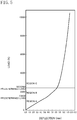
- FIG. 5 is a graph showing a load-deflection curve of the liquid-filled type vibration isolation device 1 obtained from the results of actual product measurements.
- the solid line in this figure shows a load-deflection curve obtained when a load is applied to the liquid-filled type vibration isolation device 1 of this embodiment.
- the first protruding portion 15a and the second protruding portion 15c neither come into contact nor deform in a region (a region A) where the input load is small, thereby exhibiting soft spring characteristics; only the first protruding portion 15a comes into contact and deforms as the input load increases (a region B), thereby exhibiting soft spring characteristics; and the second protruding portion 15c also comes into contact and deforms as the input load further increases (a region C), thereby exhibiting hard spring characteristics.
- Table 1 shows a relation, obtained from a simulation in which the load is applied to the liquid-filled type vibration isolation device 1 of this embodiment, between the input load and the compressive distortion (deformation amount / thickness) of the first protruding portion 15a. It has been found that the compression distortion of the first protruding portion 15a is 0.16 on average when the input load exceeds the first predetermined load and only the first protruding portion 15a comes into contact; 0.22 on average when the input load exceeds the second predetermined load and the second protruding portion 15c also starts to come into contact; and 0.55 on average when the input load further increases to approximately 10000 N.
- the liquid-filled type vibration isolation device 1 having the following three-step stopper characteristics can be achieved: the region (the region A) where, even when a load is input, the first protruding portion 15a and the second protruding portion 15c do not deform and the rubber elastic body 35 absorbs the impact; the region (the region B) where the first protruding portion 15a deforms appropriately to absorb the impact when a load is input; and the region (the region C) where the second protruding portion 15c does not considerably deform even when a load is input.
- FIG. 6 is a graph showing a relation between the dynamic spring constant in the vertical direction of the stopper rubber 15 in the contact state and the frequency, obtained from the actual product measurement result.
- the solid line in this figure shows the dynamic spring constant in the vertical direction obtained when only the first protruding portion 15a of the stopper rubber 15 of this embodiment comes into contact.
- the broken line in the figure shows the dynamic spring constant in the vertical direction obtained when a typical stopper rubber (see BACKGROUND ART) simultaneously molded on the engine bracket comes brought into contact. From the figure, it has been found that the stopper rubber 15 of this embodiment has a smaller dynamic spring constant than the typical stopper rubber.
- the stopper rubber 15 having a small dynamic spring constant in the vertical direction in the contact state can be achieved.
- the distance between the protruding end face of the first protruding portion 15a and the contact surface 21d of the rear leg portion 21b is shorter in the longitudinal direction than the distance between the protruding end face of the second protruding portion 15c and the contact surface 21d in the longitudinal direction.
- the first protruding portion 15a is thicker in the longitudinal direction than the second protruding portion 15c.
- the first protruding portion 15a has a rubber volume and exhibits soft spring characteristics. Accordingly, the first protruding portion 15a is considerably deformed. Even if the first protruding portion 15a is deformed by coming into contact with the contact surface 21d of the rear leg portion 21b at the time of input of the load in the longitudinal direction, the non-contact state between the first protruding portion 15a and the second protruding portion 15c is maintained until the second protruding portion 15c comes into contact with the contact surface 21d. Thus, the deformation of the first protruding portion 15a continues. Accordingly, the stopper rubber 15 being in contact with the rear leg portion 21b can have a small dynamic spring constant in the vertical direction.
- the second protruding portion 15c also comes into contact with the contact surface 21d of the rear leg portion 21b.
- the second protruding portion 15c is thinner in the longitudinal direction than the first protruding portion 15a.
- the second protruding portion 15c does not have a rubber volume and exhibits hard spring characteristics. Accordingly, even when a heavy load is input in the longitudinal direction, the second protruding portion 15c, and hence the rubber elastic body 35, do not considerably deform, and the displacement of the power plant can be reduced.
- the rear stopper rubber 15 being in contact with the rear leg portion 21b can have a small dynamic spring constant in the vertical direction, whereas , even when a heavy load is input in the longitudinal direction, the rubber elastic body 35 does not considerably deform, and the displacement of the power plant can be reduced.
- the non-contact state between the first protruding portion 15a and the second protruding portion 15c is maintained at all times.
- the first protruding portion 15a does not deform so as to escape in the vertical direction.
- the rear stopper rubber 15 exhibits hard spring characteristics. Accordingly, even when a heavy load is input in the longitudinal direction, the displacement of the power plant can be reliably reduced.
- the first rear end face 3e on which the first protruding portion 15a is formed is located in front of the second rear end face 3g on which the second protruding portion 15c is formed.
- the thickness in the longitudinal direction, and hence the rubber volume, of the first protruding portion 15a are maintained, whereas the protruding end face of the first protruding portion 15a can be in a more front position, compared with the case in which the first rear end face 3e is set in substantially the same position as that of the second rear end face 3g in the longitudinal direction.
- the space saving can be achieved while keeping a state in which the first protruding portion 15a exhibits soft spring characteristics.
- the contact surface 21d of the rear leg portion 21b is a plane extending in the vertical direction, and thus the configuration of the contact surface 21d can be simplified.
- the stopper rubber 15 being in contact with the rear leg portion 21b can have a small dynamic spring constant in the vertical direction.
- a muffled sound can be reduced which is generated, for example, when gear noise vibrations from the power plant in the vertical direction is transmitted to the vehicle body in a state in which the rear stopper rubber 15 is in contact with the rear leg portion 21b at the time of rapid acceleration of the vehicle.
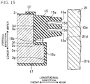
- the rear attachment base portion 3c includes a rear end face 3d having: a first rear end face 3h being flat and extending in the vertical direction; a second rear end face 3j being continuous with a lower end portion of the first rear end face 3h via a step portion 3i, located in front of the first rear end face 3h, being flat, and extending in the vertical direction; and a third rear end face 31 being continuous with a lower end portion of the second rear end face 3j via a step portion 3k, located in substantially the same position as the first rear end face 3h in the longitudinal direction, being flat, and extending in the vertical direction.
- a first protruding portion 15a has a substantially trapezoidal cross section protruding rearward from the second rear end face 3j of the rear attachment base portion 3c.
- Second protruding portions 15c each have a substantially rectangular cross section protruding rearward from the respective one of the first rear end face 3h and the second rear end face 31 of the rear attachment base portion 3c.
- the second protruding portions 15c include protruding end faces that are located in substantially the same position in the longitudinal direction. That is, the second protruding portions 15c come into contact with the contact surface 21d of the rear leg portion 21b substantially at the same time.
- the second protruding portion 15c is spaced apart in the vertical direction from the first protruding portion 15a so as to be in a non-contact state with the first protruding portion 15a.
- the second protruding portion 15c is disposed so that a groove portion 19 extending in the lateral direction is formed between the second protruding portion 15c and the first protruding portion 15a.
- the rear attachment base portion 3c includes a rear end face 3d having: a first rear end face 3m being flat and extending in the vertical direction; and a second rear end face 3o being continuous with a lower end portion of the first rear end face 3m via a step portion 3n, located in front of the first rear end face 3m, being flat, and extending in the vertical direction.
- a first protruding portion 15a has a substantially trapezoidal cross section protruding rearward from the second rear end face 3o of the rear attachment base portion 3c.
- a second protruding portion 15c has a substantially rectangular cross section protruding rearward from the first rear end face 3m of the rear attachment base portion 3c.
- the rear attachment base portion 3c includes a rear end face 3d having: a first rear end face 3p being flat and extending in the vertical direction; a second rear end face 3r being continuous with a lower end portion of the first rear end face 3p via a step portion 3q, located behind the first rear end face 3p, being flat, and extending in the vertical direction; and a third rear end face 3t being continuous with a lower end portion of the second rear end face 3r via a step portion 3s, located in substantially the same position as the first rear end face 3p in the longitudinal direction, being flat, and extending in the vertical direction.
- First protruding portions 15a each have a substantially rectangular cross section protruding rearward from the respective one of the first rear end face 3p and the third rear end face 3t of the rear attachment base portion 3c.
- the first protruding portions 15a include protruding end faces that are located in substantially the same position in the longitudinal direction. That is, the first protruding portions 15a come into contact with the contact surface 21d of the rear leg portion 21b substantially at the same time.
- a second protruding portion 15c has a substantially rectangular cross section protruding rearward from the second rear end face 3r of the rear attachment base portion 3c.
- the second protruding portion 15c is spaced apart in the vertical direction from the first protruding portion 15a so as to be in a non-contact state with the first protruding portion 15a.
- the second protruding portion 15c is disposed so that a groove portion 19 extending in the lateral direction is formed between the second protruding portion 15c and the first protruding portion 15a.
- the rear leg portion 21b includes a contact surface 21d having a first contact surface 21f being flat and extending in the vertical direction; and a second contact surface 21h being continuous with a lower end portion of the first contact surface 21f via a step portion 21g, located in front of the first contact surface 21f, being flat, and extending in the vertical direction.
- the rear attachment base portion 3c includes a rear end face 3d that is a plane extending in the vertical direction.
- a first protruding portion 15a has a substantially trapezoidal cross section protruding rearward from an upper portion of the rear face 3d of the rear attachment base portion 3c.
- a second protruding portion 15c has a substantially rectangular cross section protruding rearward from a lower portion of the rear face 3d of the rear attachment base portion 3c.
- the rear attachment base portion 3c includes a rear end face 3d that is a plane extending in the vertical direction.
- a first protruding portion 15a has a substantially trapezoidal cross section protruding rearward from an upper portion of the rear end face 3d of the rear attachment base portion 3c.
- a second protruding portion 15c is a large block having a substantially rectangular cross section protruding rearward from a lower portion of the rear end face 3d of the rear attachment base portion 3c.
- a metallic reinforcement member 27 having a substantially rectangular cross section is embedded in the second protruding portion 15c.
- the second protruding portion 15c exhibits hard spring characteristics while having a rubber volume.
- the durability of the second protruding portion 15c can be improved.
- the rear attachment base portion 3c includes a rear end face 3d that is a plane extending in the vertical direction (not shown).
- a first protruding portion 15a has a substantially cone shape protruding rearward from a center portion of the rear end face 3d of the rear attachment base portion 3c.
- a second protruding portion 15c has a substantially cylindrical shape being continuous with an end portion (a front end portion) on a side opposite to the protruding side of the first protruding portion 15a via a covered portion 15b, protruding rearward from the rear end face 3d of the rear attachment base portion 3c, and surrounding the first protruding portion 15a.
- the second protruding portion 15c is disposed substantially coaxially with the first protruding portion 15a.
- the second protruding portion 15c is spaced apart in the radial direction from the first protruding portion 15a so as to be in a non-contact state with the first protruding portion 15a.
- the second protruding portion 15c is disposed so that a circular groove portion 19 is formed between the second protruding portion 15c and the first protruding portion 15a.
- the rear leg portion 21b includes an inner surface. All or part of the inner surface serves as a formation surface 21i facing the rear stopper rubber 15 in the longitudinal direction.
- This formation surface 21i is a plane extending in the vertical direction.
- a stopper rubber 29 is formed on the formation surface 21i.
- This stopper rubber 29 includes a first protruding portion 29a protruding frontward from an upper portion of the formation surface 21i and having a substantially trapezoidal cross section extending in the lateral direction, and a second protruding portion 29b protruding frontward from a lower portion of the formation surface 21i and having a substantially rectangular cross section extending in the lateral direction.
- the second protruding portion 29b is thinner in the longitudinal direction than the first protruding portion 29a and has a smaller cross-sectional area than the first protruding portion 29a. That is, the first protruding portion 29a is relatively thicker and has a relatively larger cross-sectional area. Thus, the first protruding portion 29a has a rubber volume and exhibits soft spring characteristics. In contrast, the second protruding portion 29b is relatively thinner and has a relatively smaller cross-sectional area. Thus, the second protruding portion 29b does not have a rubber volume and exhibits hard spring characteristics.
- a protruding end face (a front end face), of the first protruding portion 29a, extending in the vertical direction is located, in the longitudinal direction, in front of a protruding end face, of the first protruding portion 29b, extending in the vertical direction.
- a first protruding portion 15a of the rear stopper rubber 15 has a substantially trapezoidal cross section facing the first protruding portion 29a of the stopper rubber 29 in the longitudinal direction.
- a second protruding portion 15c of the rear stopper rubber 15 is disposed to face the second protruding portion 29b of the stopper rubber 29 in the longitudinal direction.
- the second protruding portions 15c include a protruding end face that is located in substantially the same position in the longitudinal direction as that of the first protruding end 15a.
- the distance between the protruding end face of the second protruding portion 15c of the rear stopper rubber 15 and the protruding end face of the second protruding portion 29b of the stopper rubber 29 is longer in the longitudinal direction than the distance between the protruding end face of the first protruding portion 15a of the rear stopper rubber 15 and the protruding end face of the first protruding portion 29a of the stopper rubber 29.
- the attachment bracket 21 and the stopper rubber 29 constitute a contact member on the vehicle body side
- the protruding end faces of the first protruding portion 29a and the second protruding portion 29b of the stopper rubber 29 constitute a contact surface, of the contact member, with which the first protruding portion 15a and the second protruding portion 15c of the rear stopper rubber 15 come into contact when the load is input in the longitudinal direction.
- the contact member on the vehicle body side includes the rear leg portion 21b having the formation surface 21i facing the rear stopper rubber 15 in the longitudinal direction, and the stopper rubber 29 formed on the formation surface 21i.
- the thickness in the longitudinal direction and also the rubber volume of the rear stopper rubber 15 can be made smaller compared with the case in which the contact member does not include the stopper rubber 29.
- the durability of the rear stopper rubber 15 in particular, the fist protruding portion 15a) can be improved.
- a first protruding portion 15a includes upper and lower surfaces on each of which a groove portion 15h extending in the lateral direction is formed.
- a first protruding portion 15a has a substantially trapezoidal cross section.
- the first protruding portion 15a include a protruding end face having groove portions 15d each having a bottom portion that is located in substantially the same position in the longitudinal direction as that of a protruding end face of the second protruding portion 15c.
- the vibration isolation structure V is adopted for the liquid-filled type vibration isolation device 1, but alternatively, may be adopted for an engine mount other than the liquid-filled type vibration isolation device 1.
- the main load input direction is the longitudinal direction, but alternatively, may be the lateral direction.
- the stopper rubbers 13, 15, 17 and the rubber elastic body 35 are simultaneously molded on the engine bracket 3, but alternatively, for example, the stopper rubbers 13, 15, 17 may be attached on the engine bracket 3 later.
- the first protruding portion 15a and the second protruding portion 15c are formed on the rear end face 3d of the rear attachment base portion 3c, but alternatively, for example, may be formed on the front end face of the front attachment portion 3c instead of or in addition to the rear end face 3d of the rear attachment base portion 3c, in order to restrict the longitudinal deformation of the rubber elastic body 35 at the time of a rapid acceleration of the vehicle.
- the first protruding portion 15a and the second protruding portion 15c have a substantially rectangular or trapezoidal cross section, but alternatively, for example, the second protruding portion 15c may have a substantially semicircular cross section.
- the non-contact state between the first protruding portion 15a and the second protruding portion 15c is maintained at all times, but this non-contact state only has to be maintained until the input load in the longitudinal direction exceeds the second predetermined load and the second protruding portion 15c comes into contact with the contact surface 21d etc.
- the first protruding portion 15a and the second protruding portion 15c are integrated via the covered portion 15b, but alternatively, for example, may be separated.
- the first protrusion 15a and the second protrusion 15c of the stopper rubber 15 are formed on the rear end face 3d of the rear attachment base portion 3c, and the contact surface 21d with which the first protruding portion 15a and the second protruding portion 15c come into contact when the load is input in the longitudinal direction is formed on the inner surface of the rear leg portion 21b.
- the first protruding portion and the second protruding portion may be formed only on an inner surface of at least one of the pair of front and rear legs 21b of the attachment bracket 21, and the contact surface with which the first protruding portion and the second protruding portion come into contact when the load is input in the longitudinal direction may be formed on the outer surface, in the longitudinal direction, of the attachment base portion 3c facing that inner surface in the longitudinal direction.
- the present disclosure is applicable to a vibration isolation structure or the like.
Landscapes
- Engineering & Computer Science (AREA)
- General Engineering & Computer Science (AREA)
- Mechanical Engineering (AREA)
- Chemical & Material Sciences (AREA)
- Combustion & Propulsion (AREA)
- Transportation (AREA)
- Combined Devices Of Dampers And Springs (AREA)
- Arrangement Or Mounting Of Propulsion Units For Vehicles (AREA)
- Vibration Prevention Devices (AREA)
Abstract
Description
- The present disclosure relates to a vibration isolation structure.
- An example of a typical vibration isolation structure of this type includes a liquid-filled type vibration isolation device including a main spring portion in which an attachment metal fitting (a second attachment member) attached to a vehicle body side (a vibration receiving side) and a cylindrical body are connected together by a rubber elastic body, and an engine bracket in which a substantially cylindrical casing portion (a first attachment member) having a through hole is integrated with an attachment portion for attaching the casing portion to an engine side (a vibration origin side). Then, the cylindrical body is press-fitted into the through hole to form a liquid chamber which includes a wall portion partially comprised of the rubber elastic body and an inner peripheral surface of the casing portion, and of which the volume is variable.
- In addition, the liquid-filled type vibration isolation device of this type might include the casing portion having a stopper rubber (a stopper part). Then, for example, when a large driving reaction force acts at the time of a rapid acceleration of the vehicle and then the engine or the like is forced to be vibrated, the stopper rubber comes into contact with a member (a contact member) on the vehicle body side to restrict the deformation of the rubber elastic body in the longitudinal direction (the main load input direction) of the vehicle. For example, Japanese Patent No.
5610972 FIG. 12(a) ) discloses a liquid-filled vibration isolation device in which a rubber elastic body and a stopper rubber are simultaneously molded on an engine bracket. - To restrict vibration in the vertical direction (a direction orthogonal to the main load input direction) from the vibration origin side to the vibration receiving side in a state in which a stopper portion is in contact with the contact member, the stopper portion in the contact state is required to have a small dynamic spring constant in the vertical direction.
- On the other hand, even when a heavy load is input, a rubber elastic body is required not to considerably deform, and the displacement of a vibration origin is required to be reduced.
- Here, in Japanese Patent No.
5610972 - Thus, it is conceivable that the the stopper rubber has a deformable thick shape so as to exhibit soft spring characteristics. However, in such a case, when a heavy load is input in the longitudinal direction, the rubber elastic body considerably deforms, and the displacement of an engine cannot be reduced.
- It is an object of the present disclosure to provide a technique in which a stopper portion being in contact with a contact member has a small dynamic spring constant in a direction orthogonal to a main load input direction, whereas, even when a heavy load is input in the main load input direction, a rubber elastic body does not considerably deform, and the displacement of a vibration origin is reduced.
- The present disclosure is directed to a vibration isolation structure including a first attachment member attached to a vibration origin side; a second attachment member attached to a vibration receiving side; a rubber elastic body provided between the first attachment member and the second attachment member; a stopper portion made of rubber, provided on an end face of the first attachment member closer to an outside in a main load input direction, and restricting deformation of the rubber elastic body in the main load input direction; and a contact member provided on the vibration receiving side and having a contact surface which faces the stopper portion in the main load input direction and which the stopper portion comes into contact with at a time of input of a load in the main load input direction. The stopper portion includes a first protruding portion protruding from the end face of the first attachment portion closer to the outside in the main load input direction toward the outside in the main load input direction, and a second protruding portion protruding from the end face of the first attachment portion closer to the outside in the main load input direction toward the outside in the main load input direction, being spaced apart from the first protruding portion so as to be in a non-contact state with the first protruding portion, being thinner than the first protruding portion in the main load input direction, and having a protruding end in which a distance between the protruding end and the contact surface is longer in the main load input direction than a distance between a protruding end of the first protruding portion and the contact surface. Even if the first protruding portion is deformed by coming into contact with the contact surface at a time of input of a load in the main load input direction, the non-contact state between the first protruding portion and the second protruding portion is maintained at least until the second protruding portion comes into contact with the contact surface.
- Accordingly, the distance between the protruding end of the first protruding portion and the contact surface of the contact member is shorter in the main load input direction than the distance between the protruding end of the second protruding portion and the contact surface in the main load input direction. Thus, when the input load in the main load input direction increases and exceeds the first predetermined load, only the first protruding portion comes into contact with the contact surface.
- Here, the first protruding portion is thicker than the second protruding portion in the main load input direction. Thus, the first protruding portion has a rubber volume and exhibits soft spring characteristics. Accordingly, the first protruding portion is considerably deformed. Even if the first protruding portion is deformed by coming into contact with the contact surface of the contact member at a time of input of a load in the main load input direction, the non-contact state between the first protruding portion and the second protruding portion is maintained at least until the second protruding portion comes into contact with the contact surface. Thus, the deformation of the first protruding portion continues. Accordingly, a stopper portion being in contact with the contact member can have a small dynamic spring constant in a direction orthogonal to the main load input direction.
- Then, when the input load in the main load input direction increases and exceeds the second predetermined load larger than the first predetermined load, the second protruding portion also comes into contact with the contact surface of the contact member.
- Here, the second protruding portion is thinner than the first protruding portion in the main load input direction. Thus, the second protruding portion does not have a rubber volume and exhibits hard spring characteristics. Accordingly, even when a heavy load is input in the main input load direction, the second protruding portion, and hence the rubber elastic body, do not considerably deform, and the displacement of the vibration origin can be reduced.
- Thus, the stopper portion being in contact with the contact member has a small dynamic spring constant in a direction orthogonal to the main load input direction, whereas, even when a heavy load is input in the main load input direction, the rubber elastic body does not considerably deform, and the displacement of the vibration origin can be reduced.
- It is preferable that in the stopper portion, the non-contact state between the first protruding portion and the second protruding portion is maintained at all times.
- Accordingly, the non-contact state between the first protruding portion and the second protruding portion is maintained at all times. Thus, even when the input load in the main load input direction exceeds the second predetermined load, the first protruding portion does not deform so as to escape in a direction orthogonal to the main load input direction. Thus, the stopper portion exhibits hard spring characteristics. Accordingly, even when a heavy load is input in the main load input direction, the displacement of the vibration origin can be reliably reduced.
- It is preferable that the end face, of the first attachment member closer to the outside in the main load input direction, on which the stopper portion is formed includes a first end face on which the first protruding portion is formed, and a second end face which is located in an outer side with respect to the main load input direction than the first end face, and on which the second protruding portion is formed.
- Accordingly, the first end face on which the first protruding portion is formed is located in an inner side with respect to the main load input direction than the second end face on which the second protruding portion is formed. Thus, the thickness in the main load input direction, and hence the rubber volume, of the first protruding portion are maintained, whereas the protruding end of the first protruding portion can be located in an inner side with respect to the main load input direction, compared with the case in which the first end face is set in substantially the same position as that of the second end face. Thus, the space saving can be achieved while keeping a state in which the first protruding portion exhibits soft spring characteristics.
- It is preferable that the contact surface is a plane extending in a direction orthogonal to the main load input direction.
- Accordingly, the contact surface of the contact member is a plane extending in a direction orthogonal to the main load input direction. Thus, the configuration of the contact surface can be simplified.
- It is preferable that the contact member includes a member provided on the vibration receiving side and including a formation surface facing the stopper portion in the main load input direction, and a stopper rubber formed on the formation surface. It is also preferable that the stopper rubber includes a protruding end face which serves as the contact surface.
- Accordingly, the contact member includes the member provided on the vibration receiving side and including the formation surface facing the stopper portion in the main load input direction, and the stopper rubber formed on the formation surface. Thus, the thickness in the main load input direction, and hence the rubber volume, of the stopper portion (in particular, the first protruding portion) can be made smaller compared with the case in which the contact member does not include the stopper rubber. Thus, the durability of the stopper portion (in particular, the first protruding portion) can be improved.
- It is preferable that the vibration origin side is an engine side, the vibration receiving side is a vehicle body side, the main load input direction is a longitudinal direction of a vehicle, and the stopper portion is provided on the end face of the first attachment member closer to a rear of the vehicle.
- Meanwhile, for example, when gear noise vibrations from the engine in the vertical direction is transmitted to the vehicle body in a state in which the stopper portion is in contact with the contact member at the time of rapid acceleration of the vehicle, a muffled sound is generated.
- Here, according to the above configuration, the stopper portion being in contact with the contact member can have a small dynamic spring constant in the vertical direction. Thus, a muffled sound can be restricted which is generated, for example, when gear noise vibrations from the engine in the vertical direction is transmitted to the vehicle body in a state in which the stopper portion is in contact with the contact member at the time of rapid acceleration of the vehicle.
- According to the present disclosure, a stopper portion being in contact with a contact member has a small dynamic spring constant in a direction orthogonal to a main load input direction, whereas, even when a heavy load is input in the main load input direction, the rubber elastic body does not considerably deform, and the displacement of the vibration origin can be reduced.
-
-
FIG. 1 is a plan view showing a vibration isolation structure according to an exemplary embodiment. -
FIG. 2 is a cross-sectional view taken along the line II-II ofFIG. 1 . -
FIG. 3 is a front view showing the vibration isolation structure. -
FIG. 4 is an enlarged view of a portion surrounded by a broken line inFIG. 2 . -
FIG. 5 is a graph showing a load-deflection curve of a liquid-filled type vibration isolation device. -
FIG. 6 is a graph showing a relation between the dynamic spring constant in the vertical direction of a rear stopper rubber in the contact state and the frequency. -
FIG. 7 is a view corresponding toFIG. 4 and schematically shows a vibration isolation structure according to a first variation. -
FIG. 8 is a view corresponding toFIG. 4 and schematically shows a vibration isolation structure according to a second variation. -
FIG. 9 is a view corresponding toFIG. 4 and schematically shows a vibration isolation structure according to a third variation. -
FIG. 10 is a view corresponding toFIG. 4 and schematically shows a vibration isolation structure according to a fourth variation. -
FIG. 11 is a view corresponding toFIG. 4 and schematically shows a vibration isolation structure according to a fifth variation. -
FIG. 12 is a perspective view showing a rear stopper rubber of a vibration isolation structure according to a sixth variation. -
FIG. 13 is a view corresponding toFIG. 4 and schematically shows a vibration isolation structure according to a seventh variation. -
FIG. 14 is a view corresponding toFIG. 4 and schematically shows a vibration isolation structure according to an eighth variation. -
FIG. 15 is a view corresponding toFIG. 4 and schematically shows a vibration isolation structure according to a ninth variation. - Exemplary embodiments will now be described in detail with reference to the drawings. The following description of exemplary embodiments is only an example in nature, and is not intended to limit the scope, applications or use of the present disclosure.
-
FIGS. 1 to 4 illustrate a vibration isolation structure of this embodiment. This vibration isolation structure V is configured by fixing a liquid-filled typevibration isolation device 1 to an attachment bracket 21 (an attachment member, a member on the vibration receiving side). This liquid-filled typevibration isolation device 1 includes: anengine bracket 3 having ahollow portion 11 and attached on a power plant (not shown) (on the vibration origin side, namely on the engine side) configured by coupling an engine and a transmission; a main spring portion 5 attached to a lower side (on one side in the cylinder axis direction) of thehollow portion 11; anorifice plate 7 inserted into thehollow portion 11 from the upper side (the other side in the cylinder axis direction); adiaphragm 9 press-fitted into thehollow portion 11 from the upper side to overlap theorifice plate 7; afront stopper rubber 13 attached to a front portion (a portion on one side in the cylinder radial direction) of theengine bracket 3; a rear stopper rubber (a stopper portion) 15 attached to a rear portion (a portion on the other side in the cylinder radial direction) of theengine bracket 3; and upper andlower stopper rubbers 17 attached to upper and lower portions of theengine bracket 3, respectively. - The main spring portion 5 includes a metal inner plate (a second attachment member) 25 coupled to the vehicle body side (the vibration receiving side), and a rubber
elastic body 35 vulcanized to bond and couple thehollow portion 11 and theinner plate 25. The main spring portion 5 is attached to theengine bracket 3. Then, the liquid-filled typevibration isolation device 1 of this embodiment is attached to the power plant and the vehicle body so that the cylinder axis direction of thecore portion 45 described later is directed in the vertical direction, and that the pair of front andrear stopper rubbers rear stopper rubbers lower stopper rubbers 17, and the rubberelastic body 35 are simultaneously molded on theengine bracket 3. - In this liquid-filled type
vibration isolation device 1, a cavity defined by an inner peripheral surface of theengine bracket 3, the main spring portion 5 (specifically, the rubber elastic body 35), and thediaphragm 9 is filled with a buffer solution such as ethylene glycol. This cavity serves as aliquid chamber 31 for absorbing and alleviating vibration, of the power plant, which is input to the rubberelastic body 35. Then, the inside of thisliquid chamber 31 is partitioned into an upper side and lower side by theorifice plate 7. The lower side serves as apressure receiving chamber 31a of which the volume increases or decreases according to deformation of the rubberelastic body 35. The upper side of theliquid chamber 31 serves as anequilibrium chamber 31b of which the volume increases or decreases according to deformation of thediaphragm 9 and which absorbs the volume variation in thepressure receiving chamber 31a. - This liquid-filled type
vibration isolation device 1 is attached to the vehicle body via the substantially invertedU-shaped attachment bracket 21 attached to a vehicle body side frame (not shown) so as to straddle the liquid-filled typevibration isolation device 1 in the longitudinal direction above the liquid-filled typevibration isolation device 1, thereby elastically supporting the power plant. Thisattachment bracket 21 includes anupper beam portion 21a extending substantially horizontally in the longitudinal direction above the liquid-filledvibration isolation device 1; a pair of front andrear leg portions 21b extending downward from front and rear end portions of theupper beam portion 21a, respectively; and alower beam portion 21c extending substantially horizontally in the longitudinal direction below the liquid-filled typevibration isolation device 1 to couple thelegs 21b. The pair of front andrear leg portions 21b each includes an inner surface. All or part of the inner surface serves as acontact surface 21d facing a respective one of the pair of front andrear stopper rubbers contact surface 21d is a plane extending in the vertical direction (the direction orthogonal to the main load input direction). The pair of front andrear leg portions 21b each include alower end portion 21e fastened on the side frame. The liquid-filled typevibration isolation device 1 is attached to theattachment bracket 21 because theinner plate 25 of the main spring portion 5 is fixed to thelower beam portion 21c. - Thus, for example, when the car is stopped and the engine is in an idling state, the rubber
elastic body 35 in this liquid-filled typevibration isolation device 1 absorbs low-frequency idling vibrations caused by torque fluctuation or the like, thereby reducing vibration transmission to the vehicle body. On the other hand, for example, when a large driving reaction force (torque) acts at the time of a rapid acceleration of the vehicle and then the power plant is forced to be vibrated longitudinally, the pair of front andrear stopper rubbers front leg portion 21b and therear leg portion 21b of theattachment bracket 21, respectively, and the longitudinal deformation of the rubberelastic body 35 is restricted. When the power plant is forced to be vibrated vertically, the upper andlower stopper rubbers 17 come into contact with theupper beam portion 21a and thelower beam portion 21c of theattachment bracket 21, respectively, and the vertical deformation of the rubberelastic body 35 is restricted. - The
engine bracket 3 is made of an aluminum alloy, and theengine bracket 3 includes thehollow portion 11 that extends in the vertical direction and to which the main spring portion 5 etc. is attached as described above. In other words, thisengine bracket 3 is shaped so that a substantially cylindrical casing portion (first attachment member) 3a having thehollow portion 11 is integrated with anattachment portion 3b for attaching thecasing portion 3a to the power plant. Thecasing portion 3a includes a pair ofattachment base portions 3c, each projecting outward in the longitudinal direction from the outer peripheral surface of thecasing portion 3a and having an end face that extends in the vertical direction and faces outward in the longitudinal direction. The pair ofattachment base portions 3c is for attaching the pair of front andrear stopper rubbers attachment base portion 3c includes arear end face 3d having: a first rear end face (first end face) 3e being flat and extending in the vertical direction; and a second rear end face (second end face) 3e being continuous with a lower end portion of the firstrear end face 3e via astep portion 3f, located behind the firstrear end face 3e (located closer to the outside in the longitudinal direction), being flat, and extending in the vertical direction. Theattachment base portion 3c includes an upper surface and a lower surface on which upper andlower stopper rubbers 17 are formed, respectively. - The
hollow portion 11 of thecasing portion 3a includes an upper hollow portion 11a into which theorifice plate 7 and thediaphragm 9 are inserted, and a lower hollow portion 11c which is continuous with the upper hollow portion 11a via a step portion 11b and to which the main spring portion 5 is attached. Then, the inner diameter of the upper hollow portion 11a is larger than that of the lower hollow portion 11c. - The disc-shaped
orifice plate 7 is disposed on and above the step portion 11b, and the substantially hat-shapedrubber diaphragm 9 is disposed to cover the entirety of theorifice plate 7 from thereabove. An outer peripheral portion of thisdiaphragm 9 is press-fitted into the upper hollow portion 11a from above such that thediaphragm 9 is fitted and fixed into theengine bracket 3. - The
orifice plate 7 includes a circular orifice passage (not shown) extending in the circumferential direction. One end of the orifice passage faces and opens to thepressure receiving chamber 31a on the lower side of theliquid chamber 31, whereas the other end of the orifice passage faces and opens to theequilibrium chamber 31b on the upper side of theliquid chamber 31. Then, the buffer liquid flows between thepressure receiving chamber 31a and theequilibrium chamber 31b via the orifice passage such that the vibration having a low frequency and acting on thepressure receiving chamber 31a from the rubberelastic body 35 is attenuated. - The
inner plate 25 of the main spring portion 5 includes anattachment plate portion 55 having a substantially L-shaped cross section and having a substantially rectangularbottom plate portion 55b and aside plate portion 55a extending downward from a side edge on one side in the longer direction of thebottom plate portion 55b, and acore portion 45 having a substantially closed-top cylindrical shape in which thebottom plate portion 55b of theattachment plate portion 55 bulges upward. The rubberelastic body 35 is interposed between the outer peripheral surface of thecore portion 45 and the inner peripheral surface of the lower hollow portion 11c corresponding to the outer peripheral surface. On the other hand, by folding the side edge portion on the other side in the longer direction of thebottom plate portion 55b, theattachment plate portion 55 is attached to thelower beam portion 21c from above so as to laterally sandwich thelower beam portion 21c of theattachment bracket 21 together with theside plate portion 55a. - A mortar-shaped
recess portion 35a is formed on the lower inner peripheral side of the rubberelastic body 35, and the peripheral surface of therecess portion 35a is bonded to the outer peripheral surface of thecore portion 45. The rubberelastic body 35 expands radially outward from the entire periphery of thecore portion 45 and has a substantially truncated cone shape extending obliquely upward. The outer peripheral surface of the upper portion thereof is bonded to the inner peripheral surface of the lower hollow portion 11c. The upper portion of the rubberelastic body 35 bonded and fixed to the inner periphery of the lower hollow portion 11c in this manner has a comparatively thick cylindrical shape which opens upward. Then, the liquid-filled typevibration isolation device 1 contains theliquid chamber 31 which includes a wall portion partially comprised of the rubberelastic body 35 and the inner peripheral surface of the lower hollow portion 11c and of which the volume is variable. - The
rear stopper rubber 15 includes a first protrudingportion 15a protruding rearward (toward the outside in the main load input direction) from the firstrear end face 3e of the rearattachment base portion 3c and having a substantially rectangular cross section extending in a direction (hereinafter referred to as the lateral direction) orthogonal to the vertical direction and the longitudinal direction; and a second protrudingportion 15a being continuous with a lower end portion of the first protrudingportion 15a via a coveredportion 15b, protruding rearward from the secondrear end face 3g of the rearattachment base portion 3c, and having a substantially rectangular cross section extending in the lateral direction. - Three
ridge portions 15e extending in the lateral direction are formed on a protruding end face (a rear end face) of the first protrudingportion 15a extending in the vertical direction so as to form twogroove portions 15d. The presence of thegroove portions 15d reduces the contact area between the protruding end face of the first protrudingportion 15a and thecontact surface 21d of therear leg portion 21b at the time of input of the load in the longitudinal direction. Consequently, noises are reduced which are generated by repeated separation and contact between the protruding end face of the first protrudingportion 15a and thecontact surface 21d. - The second protruding
portion 15c serves as a displacement regulating portion for reducing displacement of the power plant (this detail will be described later). The second protrudingportion 15c is spaced apart in the vertical direction from the first protrudingportion 15a so as to be in a non-contact state with the first protrudingportion 15a. In other words, the second protrudingportion 15c is disposed so that agroove portion 19 extending in the lateral direction is formed between the second protrudingportion 15c and the first protrudingportion 15a. The non-contact state between the first protrudingportion 15a and the second protrudingportion 15c is maintained at all times even if the first protrudingportion 15a and the second protrudingportion 15c are deformed by coming into contact with thecontact surface 21d of therear leg portion 21b at the time of input of the load in the longitudinal direction. - The second protruding
portion 15c is thinner than the first protrudingportion 15a in the longitudinal direction and has a smaller cross-sectional area than the first protrudingportion 15a. That is, the first protrudingportion 15a is relatively greater in the thickness in the longitudinal direction and in the cross-sectional area. Thus, the first protrudingportion 15a has a rubber volume and exhibits soft spring characteristics. In other words, the first protrudingportion 15a is a large block having a rubber volume. In contrast, the second protrudingportion 15c is relatively smaller in the thickness in the longitudinal direction and in the cross-sectional area. Thus, the second protrudingportion 15c does not have a rubber volume and exhibits hard spring characteristics. In other words, the second protrudingportion 15c is a small block (small protrusion) not having a rubber volume. - The protruding end face, of the second protruding
portion 15c, extending in the vertical direction is located in front of the protruding end face of the first protrudingportion 15a. In other words, in the longitudinal direction, the distance between the protruding end face of the second protrudingportion 15c and thecontact surface 21d of therear leg portion 21b is longer than the distance between the protruding end face of the first protrudingportion 15a and thecontact surface 21d. - Three
ridge portions 15g extending in the lateral direction are formed on the protruding end face of the second protrudingportion 15c so as to form twogroove portions 15f. The presence of thegroove portions 15f reduces the contact area between the protruding end face of the second protrudingportion 15c and thecontact surface 21d of therear leg portion 21b at the time of input of the load in the longitudinal direction. Consequently, noises are reduced which are generated by repeated separation and contact between the second protrudingportion 15c and thecontact surface 21d. - Here, for example, when the load is input in the longitudinal direction at the time of rapid acceleration of the vehicle, the first protruding
portion 15a and the second protrudingportion 15c do not come into contact with thecontact surface 21d of therear leg portion 21b until the input load exceeds a first predetermined load (seeFIG. 5 ). - When the input load increases and exceeds the first predetermined load, only the first protruding
portion 15a comes into contact with thecontact surface 21d of therear leg portion 21b. The first protrudingportion 15a exhibits soft spring characteristics, and thus is considerably deformed. The non-contact state between the first protrudingportion 15a and the second protrudingportion 15c is maintained (thegroove 19 between the first protrudingportion 15a and the second protrudingportion 15c is not filled) even after the input load exceeds the first predetermined load, and thus the deformation of the first protrudingportion 15a continues. The second protrudingportion 15c does not come into contact with thecontact surface 21d of therear leg portion 21b until the input load exceeds a second predetermined load larger than the first predetermined load (e.g., approximately 2000 N; seeFIG. 5 ). The second predetermined load is set to the maximum load required to restrict a muffled sound caused by the transmission of the gear noise vibration to the vehicle body. This maximum load depends on the weight of the engine etc. - When the input load increases and exceeds the second predetermined load, the second protruding
portion 15c also comes into contact with thecontact surface 21d of therear leg portion 21b before the first protrudingportion 15a is deformed too much (completely crushed). In other words, the second protrudingportion 15c also comes into contact with thecontact surface 21d of therear leg portion 21b after an appropriate degree of deformation of the first protrudingportion 15a. The second protrudingportion 15c exhibits hard spring characteristics, and thus is not considerably deformed. The non-contact state between the first protrudingportion 15a and the second protrudingportion 15c is maintained even after the input load exceeds the second predetermined load, and thus the first protrudingportion 15a does not deform so as to escape in the vertical direction. Thus, therear stopper rubber 15 exhibits hard spring characteristics. -
FIG. 5 is a graph showing a load-deflection curve of the liquid-filled typevibration isolation device 1 obtained from the results of actual product measurements. The solid line in this figure shows a load-deflection curve obtained when a load is applied to the liquid-filled typevibration isolation device 1 of this embodiment. From this figure, it has been found that in the liquid-filled typevibration isolation device 1 of this embodiment, the first protrudingportion 15a and the second protrudingportion 15c neither come into contact nor deform in a region (a region A) where the input load is small, thereby exhibiting soft spring characteristics; only the first protrudingportion 15a comes into contact and deforms as the input load increases (a region B), thereby exhibiting soft spring characteristics; and the second protrudingportion 15c also comes into contact and deforms as the input load further increases (a region C), thereby exhibiting hard spring characteristics. - Table 1 shows a relation, obtained from a simulation in which the load is applied to the liquid-filled type
vibration isolation device 1 of this embodiment, between the input load and the compressive distortion (deformation amount / thickness) of the first protrudingportion 15a. It has been found that the compression distortion of the first protrudingportion 15a is 0.16 on average when the input load exceeds the first predetermined load and only the first protrudingportion 15a comes into contact; 0.22 on average when the input load exceeds the second predetermined load and the second protrudingportion 15c also starts to come into contact; and 0.55 on average when the input load further increases to approximately 10000 N. - Accordingly, the liquid-filled type
vibration isolation device 1 having the following three-step stopper characteristics can be achieved: the region (the region A) where, even when a load is input, the first protrudingportion 15a and the second protrudingportion 15c do not deform and the rubberelastic body 35 absorbs the impact; the region (the region B) where the first protrudingportion 15a deforms appropriately to absorb the impact when a load is input; and the region (the region C) where the second protrudingportion 15c does not considerably deform even when a load is input. -
FIG. 6 is a graph showing a relation between the dynamic spring constant in the vertical direction of thestopper rubber 15 in the contact state and the frequency, obtained from the actual product measurement result. The solid line in this figure shows the dynamic spring constant in the vertical direction obtained when only the first protrudingportion 15a of thestopper rubber 15 of this embodiment comes into contact. The broken line in the figure shows the dynamic spring constant in the vertical direction obtained when a typical stopper rubber (see BACKGROUND ART) simultaneously molded on the engine bracket comes brought into contact. From the figure, it has been found that thestopper rubber 15 of this embodiment has a smaller dynamic spring constant than the typical stopper rubber. - Accordingly, the
stopper rubber 15 having a small dynamic spring constant in the vertical direction in the contact state can be achieved. - Thus, according to this embodiment, the distance between the protruding end face of the first protruding
portion 15a and thecontact surface 21d of therear leg portion 21b is shorter in the longitudinal direction than the distance between the protruding end face of the second protrudingportion 15c and thecontact surface 21d in the longitudinal direction. Thus, when the input load in the longitudinal direction increases and exceeds the first predetermined load, only the first protrudingportion 15a comes into contact with thecontact surface 21d. - Here, the first protruding
portion 15a is thicker in the longitudinal direction than the second protrudingportion 15c. Thus, the first protrudingportion 15a has a rubber volume and exhibits soft spring characteristics. Accordingly, the first protrudingportion 15a is considerably deformed. Even if the first protrudingportion 15a is deformed by coming into contact with thecontact surface 21d of therear leg portion 21b at the time of input of the load in the longitudinal direction, the non-contact state between the first protrudingportion 15a and the second protrudingportion 15c is maintained until the second protrudingportion 15c comes into contact with thecontact surface 21d. Thus, the deformation of the first protrudingportion 15a continues. Accordingly, thestopper rubber 15 being in contact with therear leg portion 21b can have a small dynamic spring constant in the vertical direction. - Then, when the input load in the longitudinal direction increases and exceeds the second predetermined load larger than the first predetermined load, the second protruding
portion 15c also comes into contact with thecontact surface 21d of therear leg portion 21b. - Here, the second protruding
portion 15c is thinner in the longitudinal direction than the first protrudingportion 15a. Thus, the second protrudingportion 15c does not have a rubber volume and exhibits hard spring characteristics. Accordingly, even when a heavy load is input in the longitudinal direction, the second protrudingportion 15c, and hence the rubberelastic body 35, do not considerably deform, and the displacement of the power plant can be reduced. - Thus, the
rear stopper rubber 15 being in contact with therear leg portion 21b can have a small dynamic spring constant in the vertical direction, whereas , even when a heavy load is input in the longitudinal direction, the rubberelastic body 35 does not considerably deform, and the displacement of the power plant can be reduced. - In addition, the non-contact state between the first protruding
portion 15a and the second protrudingportion 15c is maintained at all times. Thus, even when the input load in the longitudinal direction exceeds the second predetermined load, the first protrudingportion 15a does not deform so as to escape in the vertical direction. Thus, therear stopper rubber 15 exhibits hard spring characteristics. Accordingly, even when a heavy load is input in the longitudinal direction, the displacement of the power plant can be reliably reduced. - In addition, the first
rear end face 3e on which the first protrudingportion 15a is formed is located in front of the secondrear end face 3g on which the second protrudingportion 15c is formed. Thus, the thickness in the longitudinal direction, and hence the rubber volume, of the first protrudingportion 15a are maintained, whereas the protruding end face of the first protrudingportion 15a can be in a more front position, compared with the case in which the firstrear end face 3e is set in substantially the same position as that of the secondrear end face 3g in the longitudinal direction. Thus, the space saving can be achieved while keeping a state in which the first protrudingportion 15a exhibits soft spring characteristics. - In addition, the
contact surface 21d of therear leg portion 21b is a plane extending in the vertical direction, and thus the configuration of thecontact surface 21d can be simplified. - Meanwhile, for example, when gear noise vibrations from the power plant in the vertical direction is transmitted to the vehicle body in a state in which the
rear stopper rubber 15 is in contact with therear leg portion 21b at the time of rapid acceleration of the vehicle, a muffled sound is generated. - Here, according to this embodiment, the
stopper rubber 15 being in contact with therear leg portion 21b can have a small dynamic spring constant in the vertical direction. Thus, a muffled sound can be reduced which is generated, for example, when gear noise vibrations from the power plant in the vertical direction is transmitted to the vehicle body in a state in which therear stopper rubber 15 is in contact with therear leg portion 21b at the time of rapid acceleration of the vehicle. - The configurations of the rear
attachment base portion 3c and therear stopper rubber 15 of this variation are different from those of the above-described exemplary embodiment, but the other configurations are the same as those of the above-described exemplary embodiment. Thus, in the following, the overlapping descriptions of the same components as those of the above-described exemplary embodiment might be omitted. - As shown in
FIG. 7 , the rearattachment base portion 3c includes arear end face 3d having: a firstrear end face 3h being flat and extending in the vertical direction; a secondrear end face 3j being continuous with a lower end portion of the firstrear end face 3h via astep portion 3i, located in front of the firstrear end face 3h, being flat, and extending in the vertical direction; and a third rear end face 31 being continuous with a lower end portion of the secondrear end face 3j via astep portion 3k, located in substantially the same position as the firstrear end face 3h in the longitudinal direction, being flat, and extending in the vertical direction. - A first protruding
portion 15a has a substantially trapezoidal cross section protruding rearward from the secondrear end face 3j of the rearattachment base portion 3c. Second protrudingportions 15c each have a substantially rectangular cross section protruding rearward from the respective one of the firstrear end face 3h and the second rear end face 31 of the rearattachment base portion 3c. The second protrudingportions 15c include protruding end faces that are located in substantially the same position in the longitudinal direction. That is, the second protrudingportions 15c come into contact with thecontact surface 21d of therear leg portion 21b substantially at the same time. The second protrudingportion 15c is spaced apart in the vertical direction from the first protrudingportion 15a so as to be in a non-contact state with the first protrudingportion 15a. In other words, the second protrudingportion 15c is disposed so that agroove portion 19 extending in the lateral direction is formed between the second protrudingportion 15c and the first protrudingportion 15a. - The configurations of the rear
attachment base portion 3c and therear stopper rubber 15 of this variation are different from those of the above-described exemplary embodiment, but the other configurations are the same as those of the above-described exemplary embodiment. Thus, in the following, the overlapping descriptions of the same components as those of the above-described exemplary embodiment might be omitted. - As shown in
FIG. 8 , the rearattachment base portion 3c includes arear end face 3d having: a firstrear end face 3m being flat and extending in the vertical direction; and a second rear end face 3o being continuous with a lower end portion of the firstrear end face 3m via astep portion 3n, located in front of the firstrear end face 3m, being flat, and extending in the vertical direction. A first protrudingportion 15a has a substantially trapezoidal cross section protruding rearward from the second rear end face 3o of the rearattachment base portion 3c. A second protrudingportion 15c has a substantially rectangular cross section protruding rearward from the firstrear end face 3m of the rearattachment base portion 3c. - The configurations of the rear
attachment base portion 3c and therear stopper rubber 15 of this variation are different from those of the above-described exemplary embodiment, but the other configurations are the same as those of the above-described exemplary embodiment. Thus, in the following, the overlapping descriptions of the same components as those of the above-described exemplary embodiment might be omitted. - As shown in
FIG. 9 , the rearattachment base portion 3c includes arear end face 3d having: a firstrear end face 3p being flat and extending in the vertical direction; a secondrear end face 3r being continuous with a lower end portion of the firstrear end face 3p via astep portion 3q, located behind the firstrear end face 3p, being flat, and extending in the vertical direction; and a third rear end face 3t being continuous with a lower end portion of the secondrear end face 3r via astep portion 3s, located in substantially the same position as the firstrear end face 3p in the longitudinal direction, being flat, and extending in the vertical direction. - First protruding
portions 15a each have a substantially rectangular cross section protruding rearward from the respective one of the firstrear end face 3p and the third rear end face 3t of the rearattachment base portion 3c. The first protrudingportions 15a include protruding end faces that are located in substantially the same position in the longitudinal direction. That is, the first protrudingportions 15a come into contact with thecontact surface 21d of therear leg portion 21b substantially at the same time. A second protrudingportion 15c has a substantially rectangular cross section protruding rearward from the secondrear end face 3r of the rearattachment base portion 3c. The second protrudingportion 15c is spaced apart in the vertical direction from the first protrudingportion 15a so as to be in a non-contact state with the first protrudingportion 15a. In other words, the second protrudingportion 15c is disposed so that agroove portion 19 extending in the lateral direction is formed between the second protrudingportion 15c and the first protrudingportion 15a. - The configurations of the
rear leg portion 21b, the rearattachment base portion 3c, and therear stopper rubber 15 of this variation are different from those of the above-described exemplary embodiment, but the other configurations are the same as those of the above-described exemplary embodiment. Thus, in the following, the overlapping descriptions of the same components as those of the above-described exemplary embodiment might be omitted. - As shown in
FIG. 10 , therear leg portion 21b includes acontact surface 21d having afirst contact surface 21f being flat and extending in the vertical direction; and asecond contact surface 21h being continuous with a lower end portion of thefirst contact surface 21f via astep portion 21g, located in front of thefirst contact surface 21f, being flat, and extending in the vertical direction. The rearattachment base portion 3c includes arear end face 3d that is a plane extending in the vertical direction. A first protrudingportion 15a has a substantially trapezoidal cross section protruding rearward from an upper portion of therear face 3d of the rearattachment base portion 3c. A second protrudingportion 15c has a substantially rectangular cross section protruding rearward from a lower portion of therear face 3d of the rearattachment base portion 3c. - The configurations of the
rear leg portion 21b, the rearattachment base portion 3c, and therear stopper rubber 15 of this variation are different from those of the above-described exemplary embodiment, but the other configurations are the same as those of the above-described exemplary embodiment. Thus, in the following, the overlapping descriptions of the same components as those of the above-described exemplary embodiment might be omitted. - As shown in
FIG. 11 , the rearattachment base portion 3c includes arear end face 3d that is a plane extending in the vertical direction. A first protrudingportion 15a has a substantially trapezoidal cross section protruding rearward from an upper portion of therear end face 3d of the rearattachment base portion 3c. A second protrudingportion 15c is a large block having a substantially rectangular cross section protruding rearward from a lower portion of therear end face 3d of the rearattachment base portion 3c. Ametallic reinforcement member 27 having a substantially rectangular cross section is embedded in the second protrudingportion 15c. Thus, the second protrudingportion 15c exhibits hard spring characteristics while having a rubber volume. In addition, the durability of the second protrudingportion 15c can be improved. - The configurations of the rear
attachment base portion 3c and therear stopper rubber 15 of this variation are different from those of the above-described exemplary embodiment, but the other configurations are the same as those of the above-described exemplary embodiment. Thus, in the following, the overlapping descriptions of the same components as those of the above-described exemplary embodiment might be omitted. - The rear
attachment base portion 3c includes arear end face 3d that is a plane extending in the vertical direction (not shown). As shown inFIG. 12 , a first protrudingportion 15a has a substantially cone shape protruding rearward from a center portion of therear end face 3d of the rearattachment base portion 3c. A second protrudingportion 15c has a substantially cylindrical shape being continuous with an end portion (a front end portion) on a side opposite to the protruding side of the first protrudingportion 15a via a coveredportion 15b, protruding rearward from therear end face 3d of the rearattachment base portion 3c, and surrounding the first protrudingportion 15a. The second protrudingportion 15c is disposed substantially coaxially with the first protrudingportion 15a. The second protrudingportion 15c is spaced apart in the radial direction from the first protrudingportion 15a so as to be in a non-contact state with the first protrudingportion 15a. In other words, the second protrudingportion 15c is disposed so that acircular groove portion 19 is formed between the second protrudingportion 15c and the first protrudingportion 15a. - The configurations of the
rear leg portion 21b and therear stopper rubber 15 of this variation are different from those of the above-described exemplary embodiment, but the other configurations are the same as those of the above-described exemplary embodiment. Thus, in the following, the overlapping descriptions of the same components as those of the above-described exemplary embodiment might be omitted. - As shown in
FIG. 13 , therear leg portion 21b includes an inner surface. All or part of the inner surface serves as a formation surface 21i facing therear stopper rubber 15 in the longitudinal direction. This formation surface 21i is a plane extending in the vertical direction. Astopper rubber 29 is formed on the formation surface 21i. Thisstopper rubber 29 includes a first protrudingportion 29a protruding frontward from an upper portion of the formation surface 21i and having a substantially trapezoidal cross section extending in the lateral direction, and a second protrudingportion 29b protruding frontward from a lower portion of the formation surface 21i and having a substantially rectangular cross section extending in the lateral direction. The second protrudingportion 29b is thinner in the longitudinal direction than the first protrudingportion 29a and has a smaller cross-sectional area than the first protrudingportion 29a. That is, the first protrudingportion 29a is relatively thicker and has a relatively larger cross-sectional area. Thus, the first protrudingportion 29a has a rubber volume and exhibits soft spring characteristics. In contrast, the second protrudingportion 29b is relatively thinner and has a relatively smaller cross-sectional area. Thus, the second protrudingportion 29b does not have a rubber volume and exhibits hard spring characteristics. A protruding end face (a front end face), of the first protrudingportion 29a, extending in the vertical direction is located, in the longitudinal direction, in front of a protruding end face, of the first protrudingportion 29b, extending in the vertical direction. - A first protruding
portion 15a of therear stopper rubber 15 has a substantially trapezoidal cross section facing the first protrudingportion 29a of thestopper rubber 29 in the longitudinal direction. A second protrudingportion 15c of therear stopper rubber 15 is disposed to face the second protrudingportion 29b of thestopper rubber 29 in the longitudinal direction. The second protrudingportions 15c include a protruding end face that is located in substantially the same position in the longitudinal direction as that of the firstprotruding end 15a. - The distance between the protruding end face of the second protruding
portion 15c of therear stopper rubber 15 and the protruding end face of the second protrudingportion 29b of thestopper rubber 29 is longer in the longitudinal direction than the distance between the protruding end face of the first protrudingportion 15a of therear stopper rubber 15 and the protruding end face of the first protrudingportion 29a of thestopper rubber 29. In other words, theattachment bracket 21 and thestopper rubber 29 constitute a contact member on the vehicle body side, and the protruding end faces of the first protrudingportion 29a and the second protrudingportion 29b of thestopper rubber 29 constitute a contact surface, of the contact member, with which the first protrudingportion 15a and the second protrudingportion 15c of therear stopper rubber 15 come into contact when the load is input in the longitudinal direction. - Thus, according to this variation, the contact member on the vehicle body side includes the
rear leg portion 21b having the formation surface 21i facing therear stopper rubber 15 in the longitudinal direction, and thestopper rubber 29 formed on the formation surface 21i. Thus, the thickness in the longitudinal direction and also the rubber volume of the rear stopper rubber 15 (in particular, the first protrudingportion 15a) can be made smaller compared with the case in which the contact member does not include thestopper rubber 29. Thus, the durability of the rear stopper rubber 15 (in particular, thefist protruding portion 15a) can be improved. - The configuration of the
rear stopper rubber 15 of this variation is different from that of the above-described exemplary embodiment, but the other configurations are the same as those of the above-described exemplary embodiment. Thus, in the following, the overlapping descriptions of the same components as those of the above-described exemplary embodiment might be omitted. As shown inFIG. 14 , a first protrudingportion 15a includes upper and lower surfaces on each of which agroove portion 15h extending in the lateral direction is formed. - The configuration of the
rear stopper rubber 15 of this variation is different from that of the above-described exemplary embodiment, but the other configurations are the same as those of the above-described exemplary embodiment. Thus, in the following, the overlapping descriptions of the same components as those of the above-described exemplary embodiment might be omitted. As shown inFIG. 15 , a first protrudingportion 15a has a substantially trapezoidal cross section. The first protrudingportion 15a include a protruding end face havinggroove portions 15d each having a bottom portion that is located in substantially the same position in the longitudinal direction as that of a protruding end face of the second protrudingportion 15c. - In the above-described exemplary embodiment and the above-described variations, the vibration isolation structure V is adopted for the liquid-filled type
vibration isolation device 1, but alternatively, may be adopted for an engine mount other than the liquid-filled typevibration isolation device 1. - In the above-described exemplary embodiment and the above-described variations, the main load input direction is the longitudinal direction, but alternatively, may be the lateral direction.
- In the above-described exemplary embodiment and the above-described variations, the stopper rubbers 13, 15, 17 and the rubber
elastic body 35 are simultaneously molded on theengine bracket 3, but alternatively, for example, the stopper rubbers 13, 15, 17 may be attached on theengine bracket 3 later. - In the above-described exemplary embodiment and the above-described variations, the first protruding
portion 15a and the second protrudingportion 15c are formed on therear end face 3d of the rearattachment base portion 3c, but alternatively, for example, may be formed on the front end face of thefront attachment portion 3c instead of or in addition to therear end face 3d of the rearattachment base portion 3c, in order to restrict the longitudinal deformation of the rubberelastic body 35 at the time of a rapid acceleration of the vehicle. - In the above-described exemplary embodiment and the above-described variations, the first protruding
portion 15a and the second protrudingportion 15c have a substantially rectangular or trapezoidal cross section, but alternatively, for example, the second protrudingportion 15c may have a substantially semicircular cross section. - In the above-described exemplary embodiment and the above-described variations, the non-contact state between the first protruding
portion 15a and the second protrudingportion 15c is maintained at all times, but this non-contact state only has to be maintained until the input load in the longitudinal direction exceeds the second predetermined load and the second protrudingportion 15c comes into contact with thecontact surface 21d etc. - In the above-described exemplary embodiment and the above-described variations, the first protruding
portion 15a and the second protrudingportion 15c are integrated via the coveredportion 15b, but alternatively, for example, may be separated. - In addition, the above-described exemplary embodiments and the above-described variations can be combined as appropriate unless departing from the concept of the present disclosure.
- In the above-described exemplary embodiment and the above-described variations, the
first protrusion 15a and thesecond protrusion 15c of thestopper rubber 15 are formed on therear end face 3d of the rearattachment base portion 3c, and thecontact surface 21d with which the first protrudingportion 15a and the second protrudingportion 15c come into contact when the load is input in the longitudinal direction is formed on the inner surface of therear leg portion 21b. Alternatively, for example, the first protruding portion and the second protruding portion may be formed only on an inner surface of at least one of the pair of front andrear legs 21b of theattachment bracket 21, and the contact surface with which the first protruding portion and the second protruding portion come into contact when the load is input in the longitudinal direction may be formed on the outer surface, in the longitudinal direction, of theattachment base portion 3c facing that inner surface in the longitudinal direction. - As described above, the present disclosure is applicable to a vibration isolation structure or the like.
Claims (6)
- A vibration isolation structure, comprising:a first attachment member attached to a vibration origin side;a second attachment member attached to a vibration receiving side;a rubber elastic body provided between the first attachment member and the second attachment member;a stopper portionmade of rubber,provided on an end face of the first attachment member closer to an outside in a main load input direction, andrestricting deformation of the rubber elastic body in the main load input direction; anda contact memberwhereinprovided on the vibration receiving side andhaving a contact surfacewhich faces the stopper portion in the main load input direction andwhich the stopper portion comes into contact with at a time of input of a load in the main load input direction,the stopper portion includesa first protruding portionprotruding from the end face of the first attachment portion closer to the outside in the main load input direction toward the outside in the main load input direction, anda second protruding portionprotruding from the end face of the first attachment portion closer to the outside in the main load input direction toward the outside in the main load input direction,being spaced apart from the first protruding portion so as to be in a non-contact state with the first protruding portion,being thinner than the first protruding portion in the main load input direction, andhaving a protruding end in which a distance between the protruding end and the contact surface is longer in the main load input direction than a distance between a protruding end of the first protruding portion and the contact surface, andeven if the first protruding portion is deformed by coming into contact with the contact surface at a time of input of a load in the main load input direction, the non-contact state between the first protruding portion and the second protruding portion is maintained at least until the second protruding portion comes into contact with the contact surface.
- The vibration isolation structure of claim 1, wherein
in the stopper portion, the non-contact state between the first protruding portion and the second protruding portion is maintained at all times. - The vibration isolation structure of claim 1 or 2, wherein
the end face, of the first attachment member closer to the outside in the main load input direction, on which the stopper portion is formed includesa first end face on which the first protruding portion is formed, anda second end face which is located in an outer side with respect to the main load input direction than the first end face, and on which the second protruding portion is formed. - The vibration isolation structure of any one of claims 1 to 3, wherein the contact surface is a plane extending in a direction orthogonal to the main load input direction.
- The vibration isolation structure of any one of claims 1 to 4, wherein the contact member includes a member provided on the vibration receiving side and including a formation surface facing the stopper portion in the main load input direction, and a stopper rubber formed on the formation surface, and
the stopper rubber includes a protruding end face which serves as the contact surface. - The vibration isolation structure of any one of claims 1 to 5, wherein the vibration origin side is an engine side,
the vibration receiving side is a vehicle body side,
the main load input direction is a longitudinal direction of a vehicle, and
the stopper portion is provided on the end face of the first attachment member closer to a rear of the vehicle.
Applications Claiming Priority (1)
| Application Number | Priority Date | Filing Date | Title |
|---|---|---|---|
| JP2017168802A JP7023642B2 (en) | 2017-09-01 | 2017-09-01 | Anti-vibration structure |
Publications (1)
| Publication Number | Publication Date |
|---|---|
| EP3453910A1 true EP3453910A1 (en) | 2019-03-13 |
Family
ID=63452518
Family Applications (1)
| Application Number | Title | Priority Date | Filing Date |
|---|---|---|---|
| EP18191944.0A Pending EP3453910A1 (en) | 2017-09-01 | 2018-08-31 | Vibration isolation structure |
Country Status (4)
| Country | Link |
|---|---|
| US (1) | US10807454B2 (en) |
| EP (1) | EP3453910A1 (en) |
| JP (1) | JP7023642B2 (en) |
| CN (1) | CN109424680B (en) |
Families Citing this family (6)
| Publication number | Priority date | Publication date | Assignee | Title |
|---|---|---|---|---|
| JP6579164B2 (en) * | 2017-07-26 | 2019-09-25 | マツダ株式会社 | Vehicle powertrain mount structure |
| JP7361503B2 (en) * | 2019-06-14 | 2023-10-16 | 株式会社プロスパイラ | Vibration isolator |
| CN112248786A (en) * | 2020-10-22 | 2021-01-22 | 东风汽车集团有限公司 | An engine mount bracket resonance suppression mechanism |
| DE102020216384A1 (en) * | 2020-12-21 | 2022-06-23 | Contitech Vibration Control Gmbh | Bearings, preferably engine bearings or transmission bearings |
| JP2024038695A (en) * | 2022-09-08 | 2024-03-21 | 倉敷化工株式会社 | Vibration isolator |
| FR3158918A1 (en) * | 2024-02-06 | 2025-08-08 | Stellantis Auto Sas | MOTOR VEHICLE COMPRISING A COMPRESSION-STABILIZED POWERTRAIN ATTACHMENT ANTI-TORQUE ROD |
Citations (7)
| Publication number | Priority date | Publication date | Assignee | Title |
|---|---|---|---|---|
| JPS5610972B2 (en) | 1974-12-02 | 1981-03-11 | ||
| EP1961988A2 (en) * | 2007-02-21 | 2008-08-27 | Toyota Jidosha Kabushiki Kaisha | Stopper structure and vibration-proofing structure for vehicle |
| EP2019227A1 (en) * | 2006-04-12 | 2009-01-28 | Bridgestone Corporation | Vibration damping support apparatus |
| FR2971459A1 (en) * | 2011-02-14 | 2012-08-17 | Peugeot Citroen Automobiles Sa | CONNECTING INSERT BETWEEN A MOTOR SUPPORT AND A MOTOR POWERTRAIN EQUIPPING A MOTOR VEHICLE |
| US20150252871A1 (en) * | 2014-03-06 | 2015-09-10 | Kurashiki Kako Co., Ltd. | Vibration isolator |
| US20160053848A1 (en) * | 2014-03-28 | 2016-02-25 | Sumitomo Riko Company Limited | Tubular vibration-damping device used for vibration-damping connecting rod, vibration-damping connecting rod using the same, and method of manufacturing vibration-damping connecting rod |
| EP3184853A1 (en) * | 2014-10-03 | 2017-06-28 | Bridgestone Corporation | Vibration isolation device |
Family Cites Families (24)
| Publication number | Priority date | Publication date | Assignee | Title |
|---|---|---|---|---|
| DE7417627U (en) * | 1974-05-21 | 1974-10-03 | Imexin Sa Nv | Vibration damper |
| JPS59142529U (en) * | 1983-03-15 | 1984-09-22 | 三菱自動車工業株式会社 | Engine roll stopper structure |
| JPS6192329A (en) | 1984-10-11 | 1986-05-10 | Toyo Tire & Rubber Co Ltd | Engine supporter |
| US5039170A (en) * | 1990-06-20 | 1991-08-13 | Reno Salvage Co. | Resonant beam suspension pads |
| FR2831630B1 (en) * | 2001-10-29 | 2004-01-30 | Hutchinson | HYDRAULIC ANTI-VIBRATION SUPPORT COMPRISING A CLIPSE DECOUPLING VALVE |
| JP4135719B2 (en) * | 2004-08-31 | 2008-08-20 | 東海ゴム工業株式会社 | Engine mount |
| JP2006097741A (en) * | 2004-09-28 | 2006-04-13 | Toyo Tire & Rubber Co Ltd | Engine mount |
| WO2006067849A1 (en) | 2004-12-24 | 2006-06-29 | Toyo Tire & Rubber Co., Ltd. | Liquid-sealed vibration-isolating device unit, liquid-sealed vibration-isolating device, and vehicle body side bracket |
| JP2006250209A (en) | 2005-03-09 | 2006-09-21 | Kurashiki Kako Co Ltd | Vibration isolator |
| JP4356641B2 (en) | 2005-03-31 | 2009-11-04 | 東海ゴム工業株式会社 | Torque rod |
| FR2895052B1 (en) | 2005-12-21 | 2012-06-15 | Eads Astrium Sas | MODULAR DEVICE FOR MULTI-AXIS ISOLATION OF VIBRATION AND SHOCK, BASED ON ELASOMER. |
| JP4622979B2 (en) * | 2006-09-29 | 2011-02-02 | 東海ゴム工業株式会社 | Cylindrical anti-vibration device stopper and cylindrical anti-vibration assembly |
| JP4718500B2 (en) | 2007-02-22 | 2011-07-06 | 東洋ゴム工業株式会社 | Liquid-filled vibration isolator |
| JP5186138B2 (en) | 2007-06-19 | 2013-04-17 | 東海ゴム工業株式会社 | Anti-vibration rubber stopper for railway vehicles |
| JP4755147B2 (en) | 2007-07-03 | 2011-08-24 | 東洋ゴム工業株式会社 | Vibration isolator |
| JP4583471B2 (en) | 2008-04-25 | 2010-11-17 | 東洋ゴム工業株式会社 | Liquid-filled vibration isolator unit |
| EP2345827B1 (en) * | 2008-10-09 | 2017-01-04 | Bridgestone Corporation | Anti-Vibration Device |
| JP5244244B2 (en) * | 2010-07-02 | 2013-07-24 | 東海ゴム工業株式会社 | Vibration isolator |
| JP5610972B2 (en) | 2010-10-20 | 2014-10-22 | 倉敷化工株式会社 | Liquid filled vibration isolator |
| JP6207320B2 (en) * | 2013-09-25 | 2017-10-04 | 住友理工株式会社 | Vibration isolator |
| JP6209114B2 (en) * | 2014-03-26 | 2017-10-04 | 株式会社ショーワ | Steering device |
| JP6452951B2 (en) * | 2014-05-07 | 2019-01-16 | 東洋ゴム工業株式会社 | Vibration isolator |
| JP6339472B2 (en) * | 2014-09-30 | 2018-06-06 | 山下ゴム株式会社 | Vibration isolator |
| JP6358747B2 (en) * | 2014-10-03 | 2018-07-18 | 株式会社ブリヂストン | Vibration isolator |
-
2017
- 2017-09-01 JP JP2017168802A patent/JP7023642B2/en active Active
-
2018
- 2018-08-30 CN CN201811000705.8A patent/CN109424680B/en active Active
- 2018-08-31 EP EP18191944.0A patent/EP3453910A1/en active Pending
- 2018-08-31 US US16/118,903 patent/US10807454B2/en active Active
Patent Citations (7)
| Publication number | Priority date | Publication date | Assignee | Title |
|---|---|---|---|---|
| JPS5610972B2 (en) | 1974-12-02 | 1981-03-11 | ||
| EP2019227A1 (en) * | 2006-04-12 | 2009-01-28 | Bridgestone Corporation | Vibration damping support apparatus |
| EP1961988A2 (en) * | 2007-02-21 | 2008-08-27 | Toyota Jidosha Kabushiki Kaisha | Stopper structure and vibration-proofing structure for vehicle |
| FR2971459A1 (en) * | 2011-02-14 | 2012-08-17 | Peugeot Citroen Automobiles Sa | CONNECTING INSERT BETWEEN A MOTOR SUPPORT AND A MOTOR POWERTRAIN EQUIPPING A MOTOR VEHICLE |
| US20150252871A1 (en) * | 2014-03-06 | 2015-09-10 | Kurashiki Kako Co., Ltd. | Vibration isolator |
| US20160053848A1 (en) * | 2014-03-28 | 2016-02-25 | Sumitomo Riko Company Limited | Tubular vibration-damping device used for vibration-damping connecting rod, vibration-damping connecting rod using the same, and method of manufacturing vibration-damping connecting rod |
| EP3184853A1 (en) * | 2014-10-03 | 2017-06-28 | Bridgestone Corporation | Vibration isolation device |
Also Published As
| Publication number | Publication date |
|---|---|
| US20190070945A1 (en) | 2019-03-07 |
| JP2019044871A (en) | 2019-03-22 |
| CN109424680A (en) | 2019-03-05 |
| US10807454B2 (en) | 2020-10-20 |
| CN109424680B (en) | 2021-09-28 |
| JP7023642B2 (en) | 2022-02-22 |
Similar Documents
| Publication | Publication Date | Title |
|---|---|---|
| US10807454B2 (en) | Vibration isolation structure | |
| CN105339703B (en) | Vibration isolation device | |
| CN107250600B (en) | Vibration isolator and damper | |
| US20150240901A1 (en) | Vibration damping device | |
| JP5016495B2 (en) | Liquid-filled mount and its assembly method | |
| JP5610972B2 (en) | Liquid filled vibration isolator | |
| JP5313764B2 (en) | Vibration isolator | |
| US11067146B2 (en) | Composite vibration-damping body and metal-spring-equipped composite vibration-damping body using the same | |
| JP2004232824A (en) | Strut mount | |
| JP5546415B2 (en) | Liquid filled vibration isolator | |
| JP2023159960A (en) | cylindrical mount | |
| JP2004291795A (en) | Cab mount | |
| JP5702250B2 (en) | Liquid-filled vibration isolator | |
| JP4603014B2 (en) | Liquid-filled vibration isolator | |
| JP2009144845A (en) | Vibration control device | |
| JP6452951B2 (en) | Vibration isolator | |
| JP4328589B2 (en) | Vibration isolator | |
| JP4680150B2 (en) | Vibration isolator | |
| JP5336299B2 (en) | Vibration isolator | |
| CN110050143A (en) | Antihunting device | |
| CN205715430U (en) | A kind of automobile sealed leather cup structure | |
| JP2007255530A (en) | Anti-vibration mount | |
| JP2002340080A (en) | Liquid filing type mount | |
| JP2022062338A (en) | Vibration control device | |
| JP2002286081A (en) | Liquid filled vibration damping device |
Legal Events
| Date | Code | Title | Description |
|---|---|---|---|
| PUAI | Public reference made under article 153(3) epc to a published international application that has entered the european phase |
Free format text: ORIGINAL CODE: 0009012 |
|
| STAA | Information on the status of an ep patent application or granted ep patent |
Free format text: STATUS: THE APPLICATION HAS BEEN PUBLISHED |
|
| AK | Designated contracting states |
Kind code of ref document: A1 Designated state(s): AL AT BE BG CH CY CZ DE DK EE ES FI FR GB GR HR HU IE IS IT LI LT LU LV MC MK MT NL NO PL PT RO RS SE SI SK SM TR |
|
| AX | Request for extension of the european patent |
Extension state: BA ME |
|
| STAA | Information on the status of an ep patent application or granted ep patent |
Free format text: STATUS: REQUEST FOR EXAMINATION WAS MADE |
|
| 17P | Request for examination filed |
Effective date: 20190814 |
|
| STAA | Information on the status of an ep patent application or granted ep patent |
Free format text: STATUS: EXAMINATION IS IN PROGRESS |
|
| 17Q | First examination report despatched |
Effective date: 20220407 |