EP3453858B1 - Powertrain system - Google Patents
Powertrain system Download PDFInfo
- Publication number
- EP3453858B1 EP3453858B1 EP17792641.7A EP17792641A EP3453858B1 EP 3453858 B1 EP3453858 B1 EP 3453858B1 EP 17792641 A EP17792641 A EP 17792641A EP 3453858 B1 EP3453858 B1 EP 3453858B1
- Authority
- EP
- European Patent Office
- Prior art keywords
- temperature
- fuel
- catalyst
- methane conversion
- internal combustion
- Prior art date
- Legal status (The legal status is an assumption and is not a legal conclusion. Google has not performed a legal analysis and makes no representation as to the accuracy of the status listed.)
- Not-in-force
Links
Images




Classifications
-
- F—MECHANICAL ENGINEERING; LIGHTING; HEATING; WEAPONS; BLASTING
- F02—COMBUSTION ENGINES; HOT-GAS OR COMBUSTION-PRODUCT ENGINE PLANTS
- F02D—CONTROLLING COMBUSTION ENGINES
- F02D41/00—Electrical control of supply of combustible mixture or its constituents
- F02D41/0025—Controlling engines characterised by use of non-liquid fuels, pluralities of fuels, or non-fuel substances added to the combustible mixtures
-
- F—MECHANICAL ENGINEERING; LIGHTING; HEATING; WEAPONS; BLASTING
- F02—COMBUSTION ENGINES; HOT-GAS OR COMBUSTION-PRODUCT ENGINE PLANTS
- F02B—INTERNAL-COMBUSTION PISTON ENGINES; COMBUSTION ENGINES IN GENERAL
- F02B31/00—Modifying induction systems for imparting a rotation to the charge in the cylinder
-
- F—MECHANICAL ENGINEERING; LIGHTING; HEATING; WEAPONS; BLASTING
- F02—COMBUSTION ENGINES; HOT-GAS OR COMBUSTION-PRODUCT ENGINE PLANTS
- F02B—INTERNAL-COMBUSTION PISTON ENGINES; COMBUSTION ENGINES IN GENERAL
- F02B31/00—Modifying induction systems for imparting a rotation to the charge in the cylinder
- F02B31/04—Modifying induction systems for imparting a rotation to the charge in the cylinder by means within the induction channel, e.g. deflectors
- F02B31/06—Movable means, e.g. butterfly valves
-
- F—MECHANICAL ENGINEERING; LIGHTING; HEATING; WEAPONS; BLASTING
- F02—COMBUSTION ENGINES; HOT-GAS OR COMBUSTION-PRODUCT ENGINE PLANTS
- F02D—CONTROLLING COMBUSTION ENGINES
- F02D19/00—Controlling engines characterised by their use of non-liquid fuels, pluralities of fuels, or non-fuel substances added to the combustible mixtures
- F02D19/06—Controlling engines characterised by their use of non-liquid fuels, pluralities of fuels, or non-fuel substances added to the combustible mixtures peculiar to engines working with pluralities of fuels, e.g. alternatively with light and heavy fuel oil, other than engines indifferent to the fuel consumed
- F02D19/08—Controlling engines characterised by their use of non-liquid fuels, pluralities of fuels, or non-fuel substances added to the combustible mixtures peculiar to engines working with pluralities of fuels, e.g. alternatively with light and heavy fuel oil, other than engines indifferent to the fuel consumed simultaneously using pluralities of fuels
-
- F—MECHANICAL ENGINEERING; LIGHTING; HEATING; WEAPONS; BLASTING
- F02—COMBUSTION ENGINES; HOT-GAS OR COMBUSTION-PRODUCT ENGINE PLANTS
- F02D—CONTROLLING COMBUSTION ENGINES
- F02D21/00—Controlling engines characterised by their being supplied with non-airborne oxygen or other non-fuel gas
- F02D21/06—Controlling engines characterised by their being supplied with non-airborne oxygen or other non-fuel gas peculiar to engines having other non-fuel gas added to combustion air
- F02D21/08—Controlling engines characterised by their being supplied with non-airborne oxygen or other non-fuel gas peculiar to engines having other non-fuel gas added to combustion air the other gas being the exhaust gas of engine
-
- F—MECHANICAL ENGINEERING; LIGHTING; HEATING; WEAPONS; BLASTING
- F02—COMBUSTION ENGINES; HOT-GAS OR COMBUSTION-PRODUCT ENGINE PLANTS
- F02D—CONTROLLING COMBUSTION ENGINES
- F02D41/00—Electrical control of supply of combustible mixture or its constituents
- F02D41/0025—Controlling engines characterised by use of non-liquid fuels, pluralities of fuels, or non-fuel substances added to the combustible mixtures
- F02D41/0027—Controlling engines characterised by use of non-liquid fuels, pluralities of fuels, or non-fuel substances added to the combustible mixtures the fuel being gaseous
-
- F—MECHANICAL ENGINEERING; LIGHTING; HEATING; WEAPONS; BLASTING
- F02—COMBUSTION ENGINES; HOT-GAS OR COMBUSTION-PRODUCT ENGINE PLANTS
- F02D—CONTROLLING COMBUSTION ENGINES
- F02D41/00—Electrical control of supply of combustible mixture or its constituents
- F02D41/0025—Controlling engines characterised by use of non-liquid fuels, pluralities of fuels, or non-fuel substances added to the combustible mixtures
- F02D41/0047—Controlling exhaust gas recirculation [EGR]
-
- F—MECHANICAL ENGINEERING; LIGHTING; HEATING; WEAPONS; BLASTING
- F02—COMBUSTION ENGINES; HOT-GAS OR COMBUSTION-PRODUCT ENGINE PLANTS
- F02D—CONTROLLING COMBUSTION ENGINES
- F02D43/00—Conjoint electrical control of two or more functions, e.g. ignition, fuel-air mixture, recirculation, supercharging or exhaust-gas treatment
-
- F—MECHANICAL ENGINEERING; LIGHTING; HEATING; WEAPONS; BLASTING
- F02—COMBUSTION ENGINES; HOT-GAS OR COMBUSTION-PRODUCT ENGINE PLANTS
- F02D—CONTROLLING COMBUSTION ENGINES
- F02D45/00—Electrical control not provided for in groups F02D41/00 - F02D43/00
-
- F—MECHANICAL ENGINEERING; LIGHTING; HEATING; WEAPONS; BLASTING
- F02—COMBUSTION ENGINES; HOT-GAS OR COMBUSTION-PRODUCT ENGINE PLANTS
- F02M—SUPPLYING COMBUSTION ENGINES IN GENERAL WITH COMBUSTIBLE MIXTURES OR CONSTITUENTS THEREOF
- F02M25/00—Engine-pertinent apparatus for adding non-fuel substances or small quantities of secondary fuel to combustion-air, main fuel or fuel-air mixture
-
- F—MECHANICAL ENGINEERING; LIGHTING; HEATING; WEAPONS; BLASTING
- F02—COMBUSTION ENGINES; HOT-GAS OR COMBUSTION-PRODUCT ENGINE PLANTS
- F02M—SUPPLYING COMBUSTION ENGINES IN GENERAL WITH COMBUSTIBLE MIXTURES OR CONSTITUENTS THEREOF
- F02M26/00—Engine-pertinent apparatus for adding exhaust gases to combustion-air, main fuel or fuel-air mixture, e.g. by exhaust gas recirculation [EGR] systems
- F02M26/13—Arrangement or layout of EGR passages, e.g. in relation to specific engine parts or for incorporation of accessories
- F02M26/17—Arrangement or layout of EGR passages, e.g. in relation to specific engine parts or for incorporation of accessories in relation to the intake system
-
- F—MECHANICAL ENGINEERING; LIGHTING; HEATING; WEAPONS; BLASTING
- F02—COMBUSTION ENGINES; HOT-GAS OR COMBUSTION-PRODUCT ENGINE PLANTS
- F02M—SUPPLYING COMBUSTION ENGINES IN GENERAL WITH COMBUSTIBLE MIXTURES OR CONSTITUENTS THEREOF
- F02M37/00—Apparatus or systems for feeding liquid fuel from storage containers to carburettors or fuel-injection apparatus; Arrangements for purifying liquid fuel specially adapted for, or arranged on, internal-combustion engines
-
- F—MECHANICAL ENGINEERING; LIGHTING; HEATING; WEAPONS; BLASTING
- F02—COMBUSTION ENGINES; HOT-GAS OR COMBUSTION-PRODUCT ENGINE PLANTS
- F02P—IGNITION, OTHER THAN COMPRESSION IGNITION, FOR INTERNAL-COMBUSTION ENGINES; TESTING OF IGNITION TIMING IN COMPRESSION-IGNITION ENGINES
- F02P5/00—Advancing or retarding ignition; Control therefor
- F02P5/04—Advancing or retarding ignition; Control therefor automatically, as a function of the working conditions of the engine or vehicle or of the atmospheric conditions
- F02P5/145—Advancing or retarding ignition; Control therefor automatically, as a function of the working conditions of the engine or vehicle or of the atmospheric conditions using electrical means
- F02P5/15—Digital data processing
- F02P5/1502—Digital data processing using one central computing unit
-
- F—MECHANICAL ENGINEERING; LIGHTING; HEATING; WEAPONS; BLASTING
- F02—COMBUSTION ENGINES; HOT-GAS OR COMBUSTION-PRODUCT ENGINE PLANTS
- F02P—IGNITION, OTHER THAN COMPRESSION IGNITION, FOR INTERNAL-COMBUSTION ENGINES; TESTING OF IGNITION TIMING IN COMPRESSION-IGNITION ENGINES
- F02P5/00—Advancing or retarding ignition; Control therefor
- F02P5/04—Advancing or retarding ignition; Control therefor automatically, as a function of the working conditions of the engine or vehicle or of the atmospheric conditions
- F02P5/145—Advancing or retarding ignition; Control therefor automatically, as a function of the working conditions of the engine or vehicle or of the atmospheric conditions using electrical means
- F02P5/15—Digital data processing
- F02P5/1502—Digital data processing using one central computing unit
- F02P5/1506—Digital data processing using one central computing unit with particular means during starting
-
- Y—GENERAL TAGGING OF NEW TECHNOLOGICAL DEVELOPMENTS; GENERAL TAGGING OF CROSS-SECTIONAL TECHNOLOGIES SPANNING OVER SEVERAL SECTIONS OF THE IPC; TECHNICAL SUBJECTS COVERED BY FORMER USPC CROSS-REFERENCE ART COLLECTIONS [XRACs] AND DIGESTS
- Y02—TECHNOLOGIES OR APPLICATIONS FOR MITIGATION OR ADAPTATION AGAINST CLIMATE CHANGE
- Y02T—CLIMATE CHANGE MITIGATION TECHNOLOGIES RELATED TO TRANSPORTATION
- Y02T10/00—Road transport of goods or passengers
- Y02T10/10—Internal combustion engine [ICE] based vehicles
- Y02T10/40—Engine management systems
Definitions
- the present invention relates to a power train system, and more particularly, to a power train system including a fuel reforming device for synthesizing methane from exhaust gas using a methane conversion catalyst.
- JP 2009-269983 A discloses a power train system which mixes carbon dioxide emitted from an internal combustion engine with hydrogen obtained by water decomposition or the like, applies predetermined pressure and heat in a reaction chamber to produce methane, and using the thus-obtained methane as a fuel for the internal combustion engine.
- US 2012/0145096 A1 shows an engine system with a reformer, wherein an unreformed fuel is reformed by the reformer mounted in an exhaust pipe and wherein a reformed fuel containing hydrogen is supplied to an engine.
- the engine system with a reformer includes a controller which, when the hydrogen generated by the reformer is supplied to the engine, determines a target heat generation beginning timing in accordance with load applied to an engine, an engine speed, and an air excess ratio of an air-fuel mixture, and which controls an ignition timing of the engine so that difference between a current heat generation beginning timing and the target heat generation beginning timing of the engine is within a predetermined range.
- a component ratio of a mixed fuel of synthesized methane and hydrogen (hereinafter, referred to as an auxiliary fuel) is changed by an activated state based on a temperature of a methane conversion catalyst. Therefore, there is a possibility that, in a case where the synthesized auxiliary fuel is reused as the fuel of the internal combustion engine, an optimum operating condition of the internal combustion engine is changed by the components of the auxiliary fuel. Thus, if the components of the auxiliary fuel are changed, the thermal efficiency deteriorates, which has an adverse effect on fuel economy.
- the above-described PTL 1 does not disclose or consider these points at all. Therefore, a need exists for a more practical control technology.
- An object of the present invention is to provide a novel power train system capable of improving fuel economy by adjusting an operating state of an internal combustion engine depending on components of an auxiliary fuel to be synthesized from hydrogen and carbon dioxide emitted from the internal combustion engine.
- a feature of the present invention is that an auxiliary fuel containing methane as a main component is synthesized from hydrogen and carbon dioxide which has been separated from exhaust gas using a methane conversion catalyst, and this auxiliary fuel is mixed with a main fuel and burned by an internal combustion engine (spark ignition type) and a combustion start timing or a combustion period of the internal combustion engine is adjusted depending on a temperature of the methane conversion catalyst.
- an internal combustion engine spark ignition type
- the operation of the internal combustion engine is appropriately controlled depending on the components of the auxiliary fuel to be synthesized to improve the thermal efficiency, thereby making it possible to improve the fuel economy.
- FIG. 1 shows an example of a configuration of a power train system.
- reference numeral 20 denotes a spark ignition type internal combustion engine (hereinafter, referred to as an internal combustion engine) which injects a fuel into an intake pipe
- reference numeral 21 denotes a CO2 separating means which separates carbon dioxide (hereinafter, referred to as CO2) from exhaust gas
- reference numeral 22 denotes a H2 supplying means which supplies hydrogen (hereinafter, referred to as H2)
- reference numeral 23 denotes a mixer which mixes CO2 with H2
- reference numeral 24 denotes a methane conversion catalyst
- reference numeral 25 denotes a condenser
- reference numeral 27 denotes a temperature measuring device
- reference numeral 28 denotes a controller.
- the exhaust gas from the internal combustion engine 20 is separated into a mixed gas of CO2 with moisture (hereinafter, referred to as H2O) and nitrogen (hereinafter, referred to as N 2 ) by the CO2 separating means 21.
- the mixed gas of the separated CO2 with H2O and the H2 supplied from the H2 supplying means (for example, a hydrogen cylinder) 22 are uniformly mixed by the mixer 23 and are supplied to the methane conversion catalyst 24.
- An auxiliary fuel using methane hereinafter, written by CH4 as a main component is synthesized by the methane conversion catalyst 24, and a mixed gas of the auxiliary fuel (mainly CH4) with the H2O is supplied to the condenser 25.
- the auxiliary fuel and the H2O are separated by the condenser 25, and the auxiliary fuel is used as a fuel for the internal combustion engine 20.
- An inlet temperature of the methane conversion catalyst 24 is measured by the temperature measuring device 27, and temperature data is transmitted to the controller 28.
- the controller 28 determines various control parameter values such as an ignition timing of the internal combustion engine 20 to control an operating state of the internal combustion engine 20.
- the CO2 separating means 21 can be realized by adsorbing CO2 and H2O in the exhaust gas into a CO2 capturing means 10 such as activated carbon, zeolite, and solid oxide.
- the operation process is performed by sequentially repeating a capturing process of CO2 and a desorption process of CO2.
- the inflow of the exhaust gas into the CO2 capturing means 10 is stopped and the temperature of the CO2 capturing means 10 is increased to desorb CO2 and H2O from the CO2 capturing means 10, thereby making it possible to recover CO2 and H2O.
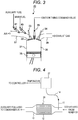
- FIG. 3 shows a combustion chamber and an intake/exhaust passage of a four-cycle type internal combustion engine.
- a piston 35 is slidably disposed in a cylinder 31, and the cylinder 31 is provided with a combustion chamber 36 of the internal combustion engine by an intake valve 33, an exhaust valve 34, and a cylinder head 32.
- Reference numeral 37 denotes an intake passage which supplies air and fuel
- reference numeral 38 denotes an exhaust passage which exhausts exhaust gas.
- reference numeral 40 denotes a main fuel injector which supplies a main fuel into the intake passage 37
- reference numeral 41 denotes an auxiliary fuel injector which supplies an auxiliary fuel to the intake passage 37
- reference numeral 39 denotes an ignition plug.
- the ignition timing by the ignition plug 39 is set by an ignition timing signal from a controller 28 (not shown) .
- the main fuel for example, a hydrocarbon fuel having a low cetane number such as gasoline, ethanol, methane, and propane is used.
- auxiliary fuel a synthetic fuel of CH4 and H2 obtained from the condenser 25 shown in FIG. 1 is used.
- the mixing ratio of CH4 and H2 of the auxiliary fuel depends on the temperature of the methane conversion catalyst 24.
- an air-fuel mixture formed by the air supplied from the intake passage 37, the main fuel supplied from the main fuel injector 40, and the auxiliary fuel supplied from the auxiliary fuel injector 41 is introduced into the combustion chamber 36.
- the air-fuel mixture in the combustion chamber compressed by the piston 35 is ignited by the ignition plug 39 at a predetermined ignition timing and burned, and therefore the piston 35 is pushed down by the explosive force of the air-fuel mixture to obtain power from the internal combustion engine 20.
- the methane conversion catalyst 24 is a catalyst that promotes a methanation reaction of CO2 and H2 shown below.
- CO2 + 4H2 > CH4 + 2H2O
- a catalyst carrier 12 is installed inside a catalyst case 13.
- the catalyst carrier 12 is a porous body made of Al, Ce, La, Ti, Zr or the like, and has Pt, Pd, Rh, Ni or the like as a catalytic active component supported on a surface thereof.
- the specific surface area of the porous carrier used in the first embodiment is preferably in the range of 30 to 800 m 2 / g, and particularly preferably in the range of 50 to 400 m 2 / g.
- the total supported amount of the catalytic active components of Pt, Pd, Rh and Ni is preferably 0.0003 parts by mol to 1. 0 part by mol with respect to 2 parts by mol of the porous carrier in terms of element. If the total supported amount of Pt, Pd, Rh and Ni is less than 0.0003 parts by mol, the supporting effect becomes insufficient. On the other hand, if the total supported amount exceeds 1.0 part by mol, the specific surface area of the active component itself is decreased, and the catalyst cost is increased.
- part by mol means a content ratio of each component in terms of mol number.
- the fact that the supported amount of “component B” is 1 part by mol with respect to 2 parts by mol of “component A” means that the “component B” is supported at a ratio of "1" to "2" of "component A” in terms of mol number irrespective of the absolute amount of "component A”.
- reference numeral 11 denotes a thermocouple whose temperature measuring portion is inserted into an exhaust passage upstream of the catalyst case 13.
- a signal of the thermocouple 11 is taken in the temperature measuring device 27 through a temperature compensation conductor 14.
- the temperature measuring device 27 obtains the catalyst temperature from the signal of the thermocouple and transmits the temperature information to the controller 28.
- the temperature of the catalyst carrier is measured by inserting the thermocouple into the inside of the catalyst carrier 12, and the measured temperature of the catalyst carrier may be used as the catalyst temperature.
- the thermocouple may be inserted into the gas passage of the catalyst outlet to measure the gas temperature at the catalyst outlet, and the measured gas temperature may be used as the catalyst temperature.
- the ignition timing by the ignition plug 39 of the internal combustion engine 20 is adjusted depending on the temperature of the methane conversion catalyst 24 measured by the temperature measuring device 27, thereby controlling the combustion start timing. If the ignition timing is shifted in an advance direction or a retard direction, a combustion start timing at which the combustion of the air-fuel mixture is started due to the ignition of the ignition plug 39.
- the catalyst temperature is decreased in a predetermined temperature range (the range of TA to TB in FIG. 11 )
- an advance amount of the ignition timing is decreased (the ignition timing is delayed) .
- the ignition timing is before the top dead center. Therefore, as the catalyst temperature is decreased, the ignition timing approaches the top dead center.
- the ignition timing is obtained by the number of revolutions, load, temperature, and the like of the internal combustion engine, but as a correction factor of the ignition timing thus obtained, the temperature of the methane conversion catalyst 24 described above may be reflected.
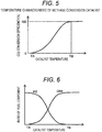
- FIG. 5 is a characteristic diagram showing the conversion efficiency of CO2 into methane in relation to the catalyst temperature.
- the conversion efficiency of the methane conversion catalyst 24 strongly depends on the catalyst temperature.
- the catalyst temperature is lower than an activation temperature TA, the function as the catalyst hardly works and the conversion rate is almost "0%”.
- the catalyst temperature exceeds the activation temperature TA, the conversion of CO2 into methane is started, and the higher the catalyst temperature, the higher the conversion efficiency.
- the conversion efficiency reaches "100% (or the upper limit conversion rate of the methane conversion catalyst)"
- the catalyst temperature when the conversion efficiency reaches "100% (or the upper limit conversion rate of the methane conversion catalyst)" is TB.
- the catalyst temperature TA and the catalyst temperature TB are variously changed depending on the supported components of the catalyst, or the like. For example, the TA is about 100 °C and the TB is about 200 °C.
- FIG. 6 is a characteristic diagram showing the ratio of the fuel component in the catalyst effluent gas in relation to the catalyst temperature.
- the conversion efficiency of the catalyst is substantially "0%", so H2 flowing into the catalyst flows out from the catalyst without reacting.
- the catalyst effluent gas almost exclusively consists of H2 fuel component.
- the conversion efficiency of the catalyst is substantially "100% (or the upper limit conversion rate of the methane conversion catalyst)", so the gas flowing out from the catalyst almost exclusively consists of CH4 fuel component.
- the conversion efficiency is decreased as the catalyst temperature is decreased, so the ratio of H2 is increased and the ratio of CH4 is decreased.
- the auxiliary fuel produced by the catalyst is a mixed fuel of CH4 and H2, and the component ratio thereof is set so that the ratio of H2 is increased as the catalyst temperature is decreased.
- FIG. 7 is a characteristic diagram showing laminar flow burning velocities of CH4 and H2.
- the laminar flow burning velocity represents a velocity at which an unburnt air-fuel mixture ahead of a flame surface is burned when the air-fuel mixture is stopped or flows in a laminar flow.
- H2 has a characteristic that the laminar flow burning velocity is much faster than that of CH4. Even in the auxiliary fuel in which H2 and CH4 are mixed, the difference in the laminar flow burning velocities of H2 and CH4 is reflected, and the higher the ratio of H2, the higher the laminar flow burning velocity of the auxiliary fuel.
- the laminar flow burning velocity of the auxiliary fuel is changed, which has a correlation as shown in FIG. 8 to the catalyst temperature. That is, in the range of the catalyst temperature from the TA to the TB, the laminar flow burning velocity of the auxiliary fuel is increased as the catalyst temperature is decreased.
- the combustion period (heat generation period) in a premix combustion is substantially inversely proportional to the laminar flow combustion velocity. Therefore, the relationship between the combustion period (heat generation period) and the catalyst temperature is as shown in FIG. 9 , and in the range of the catalyst temperature from the TA to the TB, the combustion period (heat generation period) is short as the catalyst temperature is decreased.
- FIG. 10 shows a comparison of the mass fraction burned (MFB) when two operating states in the case in which the catalyst temperature is the TA and the TB are assumed and the ignition timings thereof are the same.
- the mass fraction burned represents the ratio of the burned fuel in the fuel flowing into the combustion chamber.
- the combustion period (heat generation period) is shorter than that in the case in which the catalyst temperature is the TB, so ⁇ 50A which is the combustion timing (MFB 50) of 50% which is a combustion center when the catalyst temperature is the TA becomes an advance side as compared with ⁇ 50B which is the combustion timing (MFB 50) of 50% when the catalyst temperature is the TB.
- the MFB 50 combustion center
- the ignition timing is preset so that the air-fuel mixture is ignited to be burnt and the MFB 50 (combustion center) becomes 10 to 15 °CA after the compression top dead center.
- the ignition timing is preset so that ⁇ 50B, which is the MFB 50 (combustion center) in a state in which the conversion efficiency of the methane conversion catalyst 24 is sufficiently high, is 10 to 15 °CA after the compression top dead center. Therefore, if the temperature of the methane conversion catalyst 24 is decreased, the amount of H2 is increased to shorten the combustion period (heat generation period), so the MFB 50 (combustion center) is shifted in an advance direction more than an optimum value, and as a result, the thermal efficiency is decreased.
- the internal combustion engine is controlled so that the advance amount of the ignition timing becomes smaller as the catalyst temperature becomes lower in the range of the catalyst temperature from the TA to the TB.
- FIG. 12 shows the comparison of the mass fraction burned when the ignition timing control is performed according to the first embodiment.
- the ignition timing is controlled to be shifted to the retard side with respect to the TB as indicated by the arrow, and the heat generation period is shifted to the retard side.
- the MFB 50 combustion center
- the thermal efficiency can be increased and the fuel economy can be improved as compared with the case in which the ignition timing is not changed depending on the catalyst temperature.
- the combustion start timing is controlled by adjusting the ignition timing depending on the temperature of the methane conversion catalyst 24, but the second embodiment is different from the first embodiment in that the combustion period (heat generation period) of the air-fuel mixture is controlled depending on the temperature of the methane conversion catalyst 24.
- FIGS. 13 and 14 show a configuration of an internal combustion engine 20 according to the second embodiment.
- FIG. 13 shows a longitudinal section of the internal combustion engine 20 according to the second embodiment
- FIG. 14 shows a plane of the internal combustion engine 20 shown in FIG. 13 .
- a tumble reinforcing means which reinforces a tumble (longitudinal vortex) in a combustion chamber is provided in a passage of an intake passage 37, and other configurations of the internal combustion engine 20 are the same as the first embodiment, and therefore a description thereof will be omitted.
- the tumble reinforcing means which reinforces the tumble includes a partition wall 42 formed in a part of the passage of the intake passage 37, a rotating shaft 44 which is provided on the partition wall 42, a tumble generation valve 43 which is fixed to the rotating shaft 44, and disposed in a passage formed by the partition wall 42 and a wall surface of the intake passage 37, and an actuator 45 which drives the rotating shaft 44.
- the partition wall 42 is a plate-like member which divides a passage cross section of the intake passage 37 into upper and lower passages.
- the tumble generation valve 43 is configured to be attached to the rotating shaft 44 and rotated about the rotating shaft 44 by the actuator 45. By rotating the tumble generation valve 43, the amount of air flowing into the lower passage of the intake passage 37 divided by the partition wall 42 can be adjusted, and this adjustment amount (rotation angle) is controlled by the controller 28.
- this adjustment amount is controlled by the controller 28.
- the greater the amount of air passing through the tumble generation valve 43 the weaker the strength of the tumble.
- an opening of the tumble generation valve 43 of the internal combustion engine 20 is adjusted depending on a temperature the methane conversion catalyst 24 measured by a temperature measuring device 27. That is, the combustion period (heat generation period) is controlled by adjusting the strength of the tumble in the combustion chamber 36.
- the combustion period (heat generation period) becomes shorter as the strength of the tumble is increased, the larger the amount of H2 with a fast burning velocity, the weaker the tumble and the longer the combustion period (heat generation period) .
- a catalyst temperature is in a predetermined temperature range (the range of TA to TB in FIG. 19 )
- the opening of the tumble generation valve 43 is increased in a direction in which a flow of air passing through the tumble generation valve 43 is increased.
- FIG. 15 shows the air flow when the tumble generation valve 43 is in a fully closed state (the state in which a flow rate of air is the minimum)
- FIG. 16 shows the air flow when the tumble generation valve 43 is in a fully opened state (the state in which the flow rate of air is the maximum).
- FIG. 17 shows the change in the strength of the turbulence at a top dead center of the compression stroke in relation to the opening of the tumble generation valve 43.
- the strength of the turbulence generated by the collapse of the tumble is substantially proportional to the strength (air velocity) of the tumble generated in the combustion chamber 36. Therefore, the strength of the turbulence is decreased as the opening of the tumble generation valve 43 is increased.
- a turbulent combustion velocity of premixed gas flame is substantially proportional to the strength of the turbulence, as shown in FIG. 18 , the turbulent combustion velocity is retarded as the opening of the tumble generation valve 43 is increased. Further, it can be seen that the combustion period (heat generation period) in the premixed combustion is substantially proportional to the turbulent combustion velocity and therefore the combustion period (heat generation period) is retarded as the opening of the tumble generation valve is increased.
- FIG. 20 shows a comparison of mass fraction burned when two operating states in the case in which the catalyst temperature is TA and TB are assumed, the ignition timings in the two operating states are constant, and the tumble generation valve is fully closed.
- the catalyst temperature is the TA
- a ratio of H2 in an auxiliary fuel is higher than that in the case in which the catalyst temperature is the TB and the combustion period (heat generation period) is short
- ⁇ 50A which is MFB 50 (combustion center) when the catalyst temperature is the TA becomes an advance side as compared with ⁇ 50B which is MFB 50 (combustion center) when the catalyst temperature is the TB. Therefore, when the temperature of the methane conversion catalyst 24 is decreased, the MFB 50 (combustion center) is further shifted in an advance direction more than an optimum value, so the thermal efficiency is decreased.
- the opening of the tumble generation valve 43 is controlled to be increased as the catalyst temperature is decreased.
- FIG. 21 shows the comparison of the mass fraction burned when the opening of the tumble generation valve is controlled according to the second embodiment.
- the opening of the tumble generation valve 43 is increased to decrease the turbulent combustion velocity, so the combustion period (heat generation period) is shifted to a retard side.
- the MFB 50 combustion center
- the thermal efficiency can be further increased as compared with the case in which the opening of the tumble generation valve 43 is not changed depending on the catalyst temperature.
- the first embodiment with the second embodiment to simultaneously adjust both the opening of the tumble generation valve 43 and the ignition timing of the ignition plug 39 depending on the catalyst temperature.
- the opening of the tumble generation valve 43 may be adjusted to be increased.
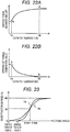
- FIG. 23 shows the change in the mass fraction burned in the case in which both the ignition timing of the ignition plug 39 and the opening of the tumble generation valve 43 are adjusted depending on the catalyst temperature.
- the catalyst temperature is low like the TA
- the combustion start timing at which heat is generated by the combustion of the air-fuel mixture is retarded, and the opening of the tumble generation valve 43 is increased, so the combustion period (heat generation period) is continued for a long time.
- ⁇ 50A which is the MFB 50 (combustion center) when the catalyst temperature is low like TA is retarded and approaches ⁇ 50B which is an optimum point, thereby making it possible to increase the thermal efficiency when the catalyst temperature is decreased.
- the amount of change in the ignition timing and the opening of the tumble generation valve can be further decreased in the case in which both the ignition timing of the ignition plug 39 and the opening of the tumble generation valve 43 are adjusted depending on the catalyst temperature than in the case in which the ignition timing of the ignition plug 39 and the opening of the tumble generation valve 43 are controlled independently.
- the component ratio of the auxiliary fuel is changed depending on the temperature of the methane conversion catalyst 24, and the MFB 50 (combustion center) deviating from the optimum point of the thermal efficiency is corrected by adjusting the combustion start timing according to the ignition timing or adjusting the combusting period (heat generation period) according to the strength of the tumble.
- the third embodiment proposes adjusting the combustion start timing or the combustion period (heat generation period) by a control parameter different from the ignition timing and the strength of the tumble.
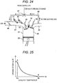
- an EGR passage 46 connecting an intake passage 37 and an exhaust pipe 38 is provided, and the amount of re-circulating gas flowing through the EGR passage 46 is adjusted by an EGR valve 47.
- an opening of the EGR valve 47 may be adjusted depending on a temperature of a methane conversion catalyst 24.
- a controller 28 may control the opening of the EGR valve 47 to be increased so as to adjust the re-circulating gas.
- the first embodiment it is also possible to combine the first embodiment with the third embodiment to simultaneously adjust both the opening of the EGR valve 47 and the ignition timing of the ignition plug 39 depending on the catalyst temperature.
- the catalyst temperature ranges from TA to TB which is a predetermined temperature range, as the catalyst temperature is decreased, an advance amount of the ignition timing may be decreased and the opening of the EGR valve may be adjusted to be increased.
- ⁇ 50A which is the MFB 50 (combustion center) when the catalyst temperature is low like TA is retarded and approaches ⁇ 50B which is an optimum point, thereby making it possible to increase the thermal efficiency when the catalyst temperature is decreased.
- the amount of change in the ignition timing and the opening of the EGR valve 47 can be further decreased in the case in which both the ignition timing of the ignition plug 39 and the opening of the EGR valve 47 are adjusted depending on the catalyst temperature than in the case in which the ignition timing of the ignition plug 39 and the opening of the EGR valve 47 are controlled independently.
- the present invention is configured to synthesize the auxiliary fuel containing methane as the main component from hydrogen and carbon dioxide which has been separated from exhaust gas using a methane conversion catalyst, mix the auxiliary fuel with the main fuel, and combust the mixed fuel in the internal combustion engine, and adjust the combustion start timing or the combustion period of the internal combustion engine depending on the temperature of the methane conversion catalyst.
- the operation of the internal combustion engine is appropriately controlled depending on the components of the auxiliary fuel to be synthesized to improve the thermal efficiency, thereby improving the fuel economy.
Landscapes
- Engineering & Computer Science (AREA)
- Chemical & Material Sciences (AREA)
- Combustion & Propulsion (AREA)
- Mechanical Engineering (AREA)
- General Engineering & Computer Science (AREA)
- Theoretical Computer Science (AREA)
- Signal Processing (AREA)
- Oil, Petroleum & Natural Gas (AREA)
- Combined Controls Of Internal Combustion Engines (AREA)
- Electrical Control Of Ignition Timing (AREA)
- Output Control And Ontrol Of Special Type Engine (AREA)
- Electrical Control Of Air Or Fuel Supplied To Internal-Combustion Engine (AREA)
Description
- The present invention relates to a power train system, and more particularly, to a power train system including a fuel reforming device for synthesizing methane from exhaust gas using a methane conversion catalyst.
- In order to suppress global warming, various' technical efforts to reduce the amount of carbon dioxide emitted from an internal combustion engine have been made. For example, attempts have been made to reduce the amount of carbon dioxide by improving thermal efficiency of the internal combustion engine by a lean-burn control for burning an air-fuel mixture thinner than a theoretical air fuel ratio or a high compression ratio control for increasing a compression ratio.
- In addition to the above attempts, a technology of providing a fuel reforming device in an internal combustion engine and synthesizing methane from carbon dioxide in exhaust gas by using a methane conversion catalyst to produce the methane as a fuel has been proposed. For example,
JP 2009-269983 A
US 2012/0145096 A1 (PTL2) shows an engine system with a reformer, wherein an unreformed fuel is reformed by the reformer mounted in an exhaust pipe and wherein a reformed fuel containing hydrogen is supplied to an engine. The engine system with a reformer includes a controller which, when the hydrogen generated by the reformer is supplied to the engine, determines a target heat generation beginning timing in accordance with load applied to an engine, an engine speed, and an air excess ratio of an air-fuel mixture, and which controls an ignition timing of the engine so that difference between a current heat generation beginning timing and the target heat generation beginning timing of the engine is within a predetermined range. -
- PTL 1:
JP 2009-269983 A - PTL 2:
US 2012/0145096 A1 - As disclosed in
PTL 1, in the method of synthesizing methane using a methane conversion catalyst, a component ratio of a mixed fuel of synthesized methane and hydrogen (hereinafter, referred to as an auxiliary fuel) is changed by an activated state based on a temperature of a methane conversion catalyst. Therefore, there is a possibility that, in a case where the synthesized auxiliary fuel is reused as the fuel of the internal combustion engine, an optimum operating condition of the internal combustion engine is changed by the components of the auxiliary fuel. Thus, if the components of the auxiliary fuel are changed, the thermal efficiency deteriorates, which has an adverse effect on fuel economy. However, the above-describedPTL 1 does not disclose or consider these points at all. Therefore, a need exists for a more practical control technology. - An object of the present invention is to provide a novel power train system capable of improving fuel economy by adjusting an operating state of an internal combustion engine depending on components of an auxiliary fuel to be synthesized from hydrogen and carbon dioxide emitted from the internal combustion engine.
- The above problem is solved by the subject matter of the appended claims. In particular, a feature of the present invention is that an auxiliary fuel containing methane as a main component is synthesized from hydrogen and carbon dioxide which has been separated from exhaust gas using a methane conversion catalyst, and this auxiliary fuel is mixed with a main fuel and burned by an internal combustion engine (spark ignition type) and a combustion start timing or a combustion period of the internal combustion engine is adjusted depending on a temperature of the methane conversion catalyst.
- According to the present invention, the operation of the internal combustion engine is appropriately controlled depending on the components of the auxiliary fuel to be synthesized to improve the thermal efficiency, thereby making it possible to improve the fuel economy.
-
- [
FIG. 1] FIG. 1 is a configuration diagram of a power train system including a reforming device according to a first embodiment of the present invention. - [
FIG. 2] FIG. 2 is a configuration diagram showing an example of a configuration of a carbon dioxide separating means shown inFIG. 1 . - [
FIG. 3] FIG. 3 is a configuration diagram showing a configuration of a spark ignition type internal combustion engine according to the first embodiment of the present invention. - [
FIG. 4] FIG. 4 is a configuration diagram showing a configuration of a methane conversion catalyst and a temperature measuring device. - [
FIG. 5] FIG. 5 is a characteristic diagram showing a temperature characteristic of the methane conversion catalyst and conversion efficiency. - [
FIG. 6] FIG. 6 is a characteristic diagram showing a ratio of a fuel component in a catalyst effluent gas in relation to a catalyst temperature. - [
FIG. 7] FIG. 7 is a characteristic diagram showing a laminar flow burning velocity of methane and hydrogen. - [
FIG. 8] FIG. 8 is a characteristic diagram showing a relationship between a catalyst temperature and a laminar flow burning velocity of an auxiliary fuel. - [
FIG. 9] FIG. 9 is a characteristic diagram showing a relationship between a combustion period (heat generation period) and the catalyst temperature. - [
FIG. 10] FIG. 10 is a characteristic diagram showing a mass fraction burned in a case in which an ignition timing is the same in an operating state in which the catalyst temperature is different. - [
FIG. 11] FIG. 11 is a characteristic diagram showing a method of setting an ignition timing in relation to a catalyst temperature. - [
FIG. 12] FIG. 12 is a characteristic diagram showing the mass fraction burned in the case in which an ignition timing control of the present invention is performed. - [
FIG. 13] FIG. 13 is a configuration diagram showing a configuration of a spark ignition type internal combustion engine according to a second embodiment of the present invention. - [
FIG. 14] FIG. 14 is a plan view of a spark ignition type internal combustion engine shown inFIG. 13 . - [
FIG. 15] FIG. 15 is an explanatory diagram showing an air flow when a tumble control valve shown inFIG. 13 is fully closed. - [
FIG. 16] FIG. 16 is an explanatory diagram showing the air flow when the tumble control valve shown inFIG. 13 is fully opened. - [
FIG. 17] FIG. 17 is a characteristic diagram showing a change in a turbulence intensity of an air-fuel mixture at a top dead center of a compression stroke in relation to an opening of a tumble generation valve. - [
FIG. 18] FIG. 18 is a characteristic diagram showing a change in a turbulent burning velocity in relation to the opening of the tumble generation valve. - [
FIG. 19] FIG. 19 is an explanatory diagram showing a method of setting a tumble generation valve in relation to a catalyst temperature. - [
FIG. 20] FIG. 20 is a characteristic diagram showing mass fraction burned in a case in which an ignition timing is constant and the tumble generation valve is fully opened in an operating state in which the catalyst temperature is different. - [
FIG. 21] FIG. 21 is a characteristic diagram showing the mass fraction burned in the case in which an opening control of the tumble generation valve is performed. - [
FIG. 22A] FIG. 22A is an explanatory diagram showing a method of setting an ignition timing in a case in which both the ignition timing and the opening of the tumble generation valve are changed depending on the catalyst temperature. - [
FIG. 22B] FIG. 22B is an explanatory diagram showing a method of setting an opening of a tumble generation valve in the case in which both the ignition timing and the opening of the tumble generation valve are changed depending on the catalyst temperature. - [
FIG. 23] FIG. 23 is a characteristic diagram showing the mass fraction burned in the case in which the ignition timing and the opening of the tumble generation valve are controlled according to the present invention. - [
FIG. 24] FIG. 24 is a configuration diagram showing a configuration of a spark ignition type internal combustion engine according to a third embodiment of the present invention. - [
FIG. 25] FIG. 25 is an explanatory diagram showing a method of setting an EGR valve in relation to a catalyst temperature. - [
FIG. 26] FIG. 26 is a characteristic diagram showing a relationship between an opening of the EGR value and a laminar flow burning velocity. - Hereinafter, embodiments of the present invention will be described in detail with reference to the drawings . However, the present invention is not limited to the embodiments described below, and various modifications are possible without departing from the scope of the appended claims.
- First, a power train system according to a first embodiment of the present invention will be described in detail with reference to
FIGS. 1 to 4 . -
FIG. 1 shows an example of a configuration of a power train system. InFIG. 1 ,reference numeral 20 denotes a spark ignition type internal combustion engine (hereinafter, referred to as an internal combustion engine) which injects a fuel into an intake pipe,reference numeral 21 denotes a CO2 separating means which separates carbon dioxide (hereinafter, referred to as CO2) from exhaust gas,reference numeral 22 denotes a H2 supplying means which supplies hydrogen (hereinafter, referred to as H2),reference numeral 23 denotes a mixer which mixes CO2 with H2,reference numeral 24 denotes a methane conversion catalyst, andreference numeral 25 denotes a condenser,reference numeral 27 denotes a temperature measuring device, andreference numeral 28 denotes a controller. - The exhaust gas from the
internal combustion engine 20 is separated into a mixed gas of CO2 with moisture (hereinafter, referred to as H2O) and nitrogen (hereinafter, referred to as N2) by the CO2 separating means 21. The mixed gas of the separated CO2 with H2O and the H2 supplied from the H2 supplying means (for example, a hydrogen cylinder) 22 are uniformly mixed by themixer 23 and are supplied to themethane conversion catalyst 24. An auxiliary fuel using methane (hereinafter, written by CH4) as a main component is synthesized by themethane conversion catalyst 24, and a mixed gas of the auxiliary fuel (mainly CH4) with the H2O is supplied to thecondenser 25. - The auxiliary fuel and the H2O are separated by the
condenser 25, and the auxiliary fuel is used as a fuel for theinternal combustion engine 20. An inlet temperature of themethane conversion catalyst 24 is measured by thetemperature measuring device 27, and temperature data is transmitted to thecontroller 28. Thecontroller 28 determines various control parameter values such as an ignition timing of theinternal combustion engine 20 to control an operating state of theinternal combustion engine 20. - Next, an example of the configuration of the CO2 separating means 21 will be described with reference to
FIG. 2 . The CO2 separating means 21 can be realized by adsorbing CO2 and H2O in the exhaust gas into a CO2 capturing means 10 such as activated carbon, zeolite, and solid oxide. The operation process is performed by sequentially repeating a capturing process of CO2 and a desorption process of CO2. - It is possible to alternately repeat the CO2 capturing process and the CO2 desorption process by installing two or more CO2 capturing means 10. In the case in which one CO2 capturing means 10 is installed in an exhaust gas flow path, if a CO2 capturing reaction by the CO2 capturing means 10 continues, the capturing capacity of CO2 and H2O of the CO2 capturing means 10 will be exceeded. In such a case, as shown in
FIG. 2 , the flow of the exhaust gas is switched by a three-way valve 11 to introduce the exhaust gas into the other CO2 capturing means 10, CO2 and H2O in the exhaust gas can be continuously supplied. - On the other hand, with regard to the CO2 capturing means 10 which sufficiently captures CO2 and H2O, the inflow of the exhaust gas into the CO2 capturing means 10 is stopped and the temperature of the CO2 capturing means 10 is increased to desorb CO2 and H2O from the CO2 capturing means 10, thereby making it possible to recover CO2 and H2O.
- By using heat discharged from the internal combustion engine to increase the temperature of the CO2 capturing means 10, it is possible to efficiently desorb CO2 and H2O in terms of energy. For example, it is possible to raise the temperature of the CO2 capturing means 10 by taking out a part of the exhaust gas of the internal combustion engine and applying the heat of the taken-out exhaust gas to the CO2 capturing means 10 via a heat medium. Alternatively, it is also possible to repeat the CO2 capturing process and the CO2 desorption process by rotating the CO2 capturing means 10.
- Next, the configuration of the
internal combustion engine 20 will be described with reference toFIG. 3. FIG. 3 shows a combustion chamber and an intake/exhaust passage of a four-cycle type internal combustion engine. Apiston 35 is slidably disposed in acylinder 31, and thecylinder 31 is provided with acombustion chamber 36 of the internal combustion engine by anintake valve 33, anexhaust valve 34, and acylinder head 32.Reference numeral 37 denotes an intake passage which supplies air and fuel, andreference numeral 38 denotes an exhaust passage which exhausts exhaust gas. - In addition,
reference numeral 40 denotes a main fuel injector which supplies a main fuel into theintake passage 37,reference numeral 41 denotes an auxiliary fuel injector which supplies an auxiliary fuel to theintake passage 37, andreference numeral 39 denotes an ignition plug. The ignition timing by theignition plug 39 is set by an ignition timing signal from a controller 28 (not shown) . As the main fuel, for example, a hydrocarbon fuel having a low cetane number such as gasoline, ethanol, methane, and propane is used. As the auxiliary fuel, a synthetic fuel of CH4 and H2 obtained from thecondenser 25 shown inFIG. 1 is used. Here, the mixing ratio of CH4 and H2 of the auxiliary fuel depends on the temperature of themethane conversion catalyst 24. - In the
internal combustion engine 20, an air-fuel mixture formed by the air supplied from theintake passage 37, the main fuel supplied from themain fuel injector 40, and the auxiliary fuel supplied from theauxiliary fuel injector 41 is introduced into thecombustion chamber 36. The air-fuel mixture in the combustion chamber compressed by thepiston 35 is ignited by theignition plug 39 at a predetermined ignition timing and burned, and therefore thepiston 35 is pushed down by the explosive force of the air-fuel mixture to obtain power from theinternal combustion engine 20. - Next, the configuration of the
methane conversion catalyst 24 and thetemperature measuring device 27 will be described with reference toFIG. 4 . Here, themethane conversion catalyst 24 is a catalyst that promotes a methanation reaction of CO2 and H2 shown below.
CO2 + 4H2 => CH4 + 2H2O
- In
FIG. 4 , acatalyst carrier 12 is installed inside acatalyst case 13. Thecatalyst carrier 12 is a porous body made of Al, Ce, La, Ti, Zr or the like, and has Pt, Pd, Rh, Ni or the like as a catalytic active component supported on a surface thereof. - By using an oxide having a high specific surface area as the porous carrier of the
methane conversion catalyst 24, Pt, Pd, Rh, and Ni are highly dispersed and the methanation performance is enhanced. In particular, if the oxide containing Al is used as the porous carrier, the high methanation performance can be obtained stably. The specific surface area of the porous carrier used in the first embodiment is preferably in the range of 30 to 800 m2 / g, and particularly preferably in the range of 50 to 400 m2 / g. - In addition, two or more kinds selected from Pt, Pd, Rh and Ni may be contained as the catalytic active component. The total supported amount of the catalytic active components of Pt, Pd, Rh and Ni is preferably 0.0003 parts by mol to 1. 0 part by mol with respect to 2 parts by mol of the porous carrier in terms of element. If the total supported amount of Pt, Pd, Rh and Ni is less than 0.0003 parts by mol, the supporting effect becomes insufficient. On the other hand, if the total supported amount exceeds 1.0 part by mol, the specific surface area of the active component itself is decreased, and the catalyst cost is increased.
- Here, "part by mol" means a content ratio of each component in terms of mol number. For example, the fact that the supported amount of "component B" is 1 part by mol with respect to 2 parts by mol of "component A" means that the "component B" is supported at a ratio of "1" to "2" of "component A" in terms of mol number irrespective of the absolute amount of "component A".
- In
FIG. 4 ,reference numeral 11 denotes a thermocouple whose temperature measuring portion is inserted into an exhaust passage upstream of thecatalyst case 13. A signal of thethermocouple 11 is taken in thetemperature measuring device 27 through atemperature compensation conductor 14. Thetemperature measuring device 27 obtains the catalyst temperature from the signal of the thermocouple and transmits the temperature information to thecontroller 28. - Although the example in which the gas temperature at the catalyst inlet is used as the catalyst temperature is shown in the first embodiment, the temperature of the catalyst carrier is measured by inserting the thermocouple into the inside of the
catalyst carrier 12, and the measured temperature of the catalyst carrier may be used as the catalyst temperature. Alternatively, the thermocouple may be inserted into the gas passage of the catalyst outlet to measure the gas temperature at the catalyst outlet, and the measured gas temperature may be used as the catalyst temperature. - In the first embodiment, in the power train system shown in
FIGS. 1 to 4 , the ignition timing by the ignition plug 39 of theinternal combustion engine 20 is adjusted depending on the temperature of themethane conversion catalyst 24 measured by thetemperature measuring device 27, thereby controlling the combustion start timing. If the ignition timing is shifted in an advance direction or a retard direction, a combustion start timing at which the combustion of the air-fuel mixture is started due to the ignition of theignition plug 39. - In other words, as shown in
FIG. 11 , as the catalyst temperature is decreased in a predetermined temperature range (the range of TA to TB inFIG. 11 ), an advance amount of the ignition timing is decreased (the ignition timing is delayed) . In this case, it is assumed that the ignition timing is before the top dead center. Therefore, as the catalyst temperature is decreased, the ignition timing approaches the top dead center. As is known well, the ignition timing is obtained by the number of revolutions, load, temperature, and the like of the internal combustion engine, but as a correction factor of the ignition timing thus obtained, the temperature of themethane conversion catalyst 24 described above may be reflected. - Operations, actions and effects of the first embodiment will be described with reference to
FIGS. 5 to 12 . First, the temperature characteristics of themethane conversion catalyst 24 will be described with reference toFIG. 5 . -
FIG. 5 is a characteristic diagram showing the conversion efficiency of CO2 into methane in relation to the catalyst temperature. In general, the conversion efficiency of themethane conversion catalyst 24 strongly depends on the catalyst temperature. When the catalyst temperature is lower than an activation temperature TA, the function as the catalyst hardly works and the conversion rate is almost "0%". On the other hand, when the catalyst temperature exceeds the activation temperature TA, the conversion of CO2 into methane is started, and the higher the catalyst temperature, the higher the conversion efficiency. When the conversion efficiency reaches "100% (or the upper limit conversion rate of the methane conversion catalyst)", the conversion rate becomes substantially constant against the increase in the catalyst temperature. The catalyst temperature when the conversion efficiency reaches "100% (or the upper limit conversion rate of the methane conversion catalyst)" is TB. The catalyst temperature TA and the catalyst temperature TB are variously changed depending on the supported components of the catalyst, or the like. For example, the TA is about 100 °C and the TB is about 200 °C. - As described above, the conversion efficiency is changed between the TA and the TB depending on the catalyst temperature, so the fuel components of the gas flowing out from the catalyst are changed depending on the catalyst temperature.
FIG. 6 is a characteristic diagram showing the ratio of the fuel component in the catalyst effluent gas in relation to the catalyst temperature. When the catalyst temperature is lower than the TA, the conversion efficiency of the catalyst is substantially "0%", so H2 flowing into the catalyst flows out from the catalyst without reacting. - Therefore, when the catalyst temperature is lower than the TA, the catalyst effluent gas almost exclusively consists of H2 fuel component. On the other hand, when the catalyst temperature is higher than the TB, the conversion efficiency of the catalyst is substantially "100% (or the upper limit conversion rate of the methane conversion catalyst)", so the gas flowing out from the catalyst almost exclusively consists of CH4 fuel component. In the range of the catalyst temperature from the TA to the TB, the conversion efficiency is decreased as the catalyst temperature is decreased, so the ratio of H2 is increased and the ratio of CH4 is decreased.
- That is, in the range of the catalyst temperature from the TA to the TB, the auxiliary fuel produced by the catalyst is a mixed fuel of CH4 and H2, and the component ratio thereof is set so that the ratio of H2 is increased as the catalyst temperature is decreased.
-
FIG. 7 is a characteristic diagram showing laminar flow burning velocities of CH4 and H2. Here, the laminar flow burning velocity represents a velocity at which an unburnt air-fuel mixture ahead of a flame surface is burned when the air-fuel mixture is stopped or flows in a laminar flow. H2 has a characteristic that the laminar flow burning velocity is much faster than that of CH4. Even in the auxiliary fuel in which H2 and CH4 are mixed, the difference in the laminar flow burning velocities of H2 and CH4 is reflected, and the higher the ratio of H2, the higher the laminar flow burning velocity of the auxiliary fuel. - As described above, since the laminar flow burning velocity is changed depending on a mixing ratio of H2 and CH4, when the ratio of H2 and CH4 of the auxiliary fuel is changed depending on the catalyst temperature, the laminar flow burning velocity of the auxiliary fuel is changed, which has a correlation as shown in
FIG. 8 to the catalyst temperature. That is, in the range of the catalyst temperature from the TA to the TB, the laminar flow burning velocity of the auxiliary fuel is increased as the catalyst temperature is decreased. - In addition, the combustion period (heat generation period) in a premix combustion is substantially inversely proportional to the laminar flow combustion velocity. Therefore, the relationship between the combustion period (heat generation period) and the catalyst temperature is as shown in
FIG. 9 , and in the range of the catalyst temperature from the TA to the TB, the combustion period (heat generation period) is short as the catalyst temperature is decreased.FIG. 10 shows a comparison of the mass fraction burned (MFB) when two operating states in the case in which the catalyst temperature is the TA and the TB are assumed and the ignition timings thereof are the same. Here, the mass fraction burned represents the ratio of the burned fuel in the fuel flowing into the combustion chamber. - In the case in which the catalyst temperature is the TA, the combustion period (heat generation period) is shorter than that in the case in which the catalyst temperature is the TB, so θ50A which is the combustion timing (MFB 50) of 50% which is a combustion center when the catalyst temperature is the TA becomes an advance side as compared with θ50B which is the combustion timing (MFB 50) of 50% when the catalyst temperature is the TB. In general, it is known that in the internal combustion engine, if the MFB 50 (combustion center) is set to be 10 to 15 °CA after the compression top dead center, the thermal efficiency becomes the best. Therefore, the ignition timing is preset so that the air-fuel mixture is ignited to be burnt and the MFB 50 (combustion center) becomes 10 to 15 °CA after the compression top dead center.
- Specifically, the ignition timing is preset so that θ50B, which is the MFB 50 (combustion center) in a state in which the conversion efficiency of the
methane conversion catalyst 24 is sufficiently high, is 10 to 15 °CA after the compression top dead center. Therefore, if the temperature of themethane conversion catalyst 24 is decreased, the amount of H2 is increased to shorten the combustion period (heat generation period), so the MFB 50 (combustion center) is shifted in an advance direction more than an optimum value, and as a result, the thermal efficiency is decreased. - Therefore, in the first embodiment, as shown in
FIG. 11 , the internal combustion engine is controlled so that the advance amount of the ignition timing becomes smaller as the catalyst temperature becomes lower in the range of the catalyst temperature from the TA to the TB. -
FIG. 12 shows the comparison of the mass fraction burned when the ignition timing control is performed according to the first embodiment. In the case of the TA in which the catalyst temperature is decreased and the combustion period (heat generation period) is short, the ignition timing is controlled to be shifted to the retard side with respect to the TB as indicated by the arrow, and the heat generation period is shifted to the retard side. As a result, even when the catalyst temperature is decreased, the MFB 50 (combustion center) can approach the optimum position, and the thermal efficiency can be increased and the fuel economy can be improved as compared with the case in which the ignition timing is not changed depending on the catalyst temperature. - Next, a second embodiment of the present invention will be described with reference to
FIGS. 13 to 23 . In the first embodiment, the combustion start timing is controlled by adjusting the ignition timing depending on the temperature of themethane conversion catalyst 24, but the second embodiment is different from the first embodiment in that the combustion period (heat generation period) of the air-fuel mixture is controlled depending on the temperature of themethane conversion catalyst 24. - A configuration of a power train system according to the second embodiment is the same as that of the first embodiment, and therefore a detailed description thereof will be omitted. Here,
FIGS. 13 and14 show a configuration of aninternal combustion engine 20 according to the second embodiment.FIG. 13 shows a longitudinal section of theinternal combustion engine 20 according to the second embodiment, andFIG. 14 shows a plane of theinternal combustion engine 20 shown inFIG. 13 . - In the configuration of the
internal combustion engine 20 according to the second embodiment, a tumble reinforcing means which reinforces a tumble (longitudinal vortex) in a combustion chamber is provided in a passage of anintake passage 37, and other configurations of theinternal combustion engine 20 are the same as the first embodiment, and therefore a description thereof will be omitted. - The tumble reinforcing means which reinforces the tumble includes a
partition wall 42 formed in a part of the passage of theintake passage 37, a rotatingshaft 44 which is provided on thepartition wall 42, atumble generation valve 43 which is fixed to therotating shaft 44, and disposed in a passage formed by thepartition wall 42 and a wall surface of theintake passage 37, and anactuator 45 which drives the rotatingshaft 44. - As shown in
FIGS. 13 and14 , thepartition wall 42 is a plate-like member which divides a passage cross section of theintake passage 37 into upper and lower passages. Thetumble generation valve 43 is configured to be attached to therotating shaft 44 and rotated about the rotatingshaft 44 by theactuator 45. By rotating thetumble generation valve 43, the amount of air flowing into the lower passage of theintake passage 37 divided by thepartition wall 42 can be adjusted, and this adjustment amount (rotation angle) is controlled by thecontroller 28. Here, the greater the amount of air passing through thetumble generation valve 43, the weaker the strength of the tumble. - In the second embodiment, in the power train system shown in
FIGS. 1, 2 ,4 ,13 , and14 , an opening of thetumble generation valve 43 of theinternal combustion engine 20 is adjusted depending on a temperature themethane conversion catalyst 24 measured by atemperature measuring device 27. That is, the combustion period (heat generation period) is controlled by adjusting the strength of the tumble in thecombustion chamber 36. - Since the combustion period (heat generation period) becomes shorter as the strength of the tumble is increased, the larger the amount of H2 with a fast burning velocity, the weaker the tumble and the longer the combustion period (heat generation period) . For this reason, as shown in
FIG. 19 , when a catalyst temperature is in a predetermined temperature range (the range of TA to TB inFIG. 19 ), as the catalyst temperature at which H2 is increased is decreased, the opening of thetumble generation valve 43 is increased in a direction in which a flow of air passing through thetumble generation valve 43 is increased. - Operations, actions and effects of the second embodiment will be described with reference to
FIGS. 15 to 21 , but first, a difference in the air flow in the combustion chamber due to a difference in the opening of thetumble generation valve 43 will be described by usingFIGS. 15 and16 .FIG. 15 shows the air flow when thetumble generation valve 43 is in a fully closed state (the state in which a flow rate of air is the minimum), andFIG. 16 shows the air flow when thetumble generation valve 43 is in a fully opened state (the state in which the flow rate of air is the maximum). - As shown in
FIG. 15 , when thetumble generation valve 43 is fully closed, air does not flow into the passage under thepartition wall 42 of theintake passage 37, but mainly flows in thecombustion chamber 36 through an upper side of the opening portion of theintake valve 33. Therefore, a strong tumble is generated in thecombustion chamber 36. - On the other hand, as shown in
FIG. 16 , when thetumble generation valve 43 is in the fully opened state, air equally flows in the upper and lower passages of thepartition wall 42 of theintake passage 37, and thus substantially equally flows in thecombustion chamber 36 from upper and lower sides of the opening portion of theintake valve 33. For this reason, the tumble generated in thecombustion chamber 36 is weaker (the air velocity is retarded) than the tumble generated when thetumble generation valve 43 is in the fully closed state. - The tumble generated in the
combustion chamber 36 collapses in a later stage of a compression stroke to generate turbulence (turbulent flow) in thecombustion chamber 36.FIG. 17 shows the change in the strength of the turbulence at a top dead center of the compression stroke in relation to the opening of thetumble generation valve 43. The strength of the turbulence generated by the collapse of the tumble is substantially proportional to the strength (air velocity) of the tumble generated in thecombustion chamber 36. Therefore, the strength of the turbulence is decreased as the opening of thetumble generation valve 43 is increased. - Since a turbulent combustion velocity of premixed gas flame is substantially proportional to the strength of the turbulence, as shown in
FIG. 18 , the turbulent combustion velocity is retarded as the opening of thetumble generation valve 43 is increased. Further, it can be seen that the combustion period (heat generation period) in the premixed combustion is substantially proportional to the turbulent combustion velocity and therefore the combustion period (heat generation period) is retarded as the opening of the tumble generation valve is increased. -
FIG. 20 shows a comparison of mass fraction burned when two operating states in the case in which the catalyst temperature is TA and TB are assumed, the ignition timings in the two operating states are constant, and the tumble generation valve is fully closed. - In the case in which the catalyst temperature is the TA, a ratio of H2 in an auxiliary fuel is higher than that in the case in which the catalyst temperature is the TB and the combustion period (heat generation period) is short, so θ50A which is MFB 50 (combustion center) when the catalyst temperature is the TA becomes an advance side as compared with θ50B which is MFB 50 (combustion center) when the catalyst temperature is the TB. Therefore, when the temperature of the
methane conversion catalyst 24 is decreased, the MFB 50 (combustion center) is further shifted in an advance direction more than an optimum value, so the thermal efficiency is decreased. - In the second embodiment, as shown in
FIG. 19 , in the range of the catalyst temperature from the TA to TB, the opening of thetumble generation valve 43 is controlled to be increased as the catalyst temperature is decreased. -
FIG. 21 shows the comparison of the mass fraction burned when the opening of the tumble generation valve is controlled according to the second embodiment. In the case of the TA in which the catalyst temperature is decreased and the combustion period (heat generation period) is short, the opening of thetumble generation valve 43 is increased to decrease the turbulent combustion velocity, so the combustion period (heat generation period) is shifted to a retard side. As a result, even in the case in which the catalyst temperature is decreased, the MFB 50 (combustion center) can approach the optimum position, and the thermal efficiency can be further increased as compared with the case in which the opening of thetumble generation valve 43 is not changed depending on the catalyst temperature. - In addition, it is also possible to combine the first embodiment with the second embodiment to simultaneously adjust both the opening of the
tumble generation valve 43 and the ignition timing of theignition plug 39 depending on the catalyst temperature. In the range of the catalyst temperature from the predetermined temperature range of TA to TB, as shown inFIG. 22A , as the catalyst temperature is decreased, the advance amount of the ignition timing is decreased, and as shown inFIG. 22B , the opening of thetumble generation valve 43 may be adjusted to be increased. -
FIG. 23 shows the change in the mass fraction burned in the case in which both the ignition timing of theignition plug 39 and the opening of thetumble generation valve 43 are adjusted depending on the catalyst temperature. In the case in which the catalyst temperature is low like the TA, by retarding the ignition timing of theignition plug 39, the combustion start timing at which heat is generated by the combustion of the air-fuel mixture is retarded, and the opening of thetumble generation valve 43 is increased, so the combustion period (heat generation period) is continued for a long time. - By both the effects, θ50A which is the MFB 50 (combustion center) when the catalyst temperature is low like TA is retarded and approaches θ50B which is an optimum point, thereby making it possible to increase the thermal efficiency when the catalyst temperature is decreased. In this way, the amount of change in the ignition timing and the opening of the tumble generation valve can be further decreased in the case in which both the ignition timing of the
ignition plug 39 and the opening of thetumble generation valve 43 are adjusted depending on the catalyst temperature than in the case in which the ignition timing of theignition plug 39 and the opening of thetumble generation valve 43 are controlled independently. - When the amount of change in the control parameter value of the internal combustion engine is increased, there is a problem that the combustion becomes unstable in transition or transient followability deteriorates. However, the above-described method can reduce the changes in each control amount, and therefore has an advantage over these problems.
- Next, a third embodiment of the present invention will be described with reference to
FIGS. 24 to 26 . In the first embodiment and the second embodiment, the component ratio of the auxiliary fuel is changed depending on the temperature of themethane conversion catalyst 24, and the MFB 50 (combustion center) deviating from the optimum point of the thermal efficiency is corrected by adjusting the combustion start timing according to the ignition timing or adjusting the combusting period (heat generation period) according to the strength of the tumble. On the other hand, the third embodiment proposes adjusting the combustion start timing or the combustion period (heat generation period) by a control parameter different from the ignition timing and the strength of the tumble. - In an internal combustion engine shown in
FIG. 24 , anEGR passage 46 connecting anintake passage 37 and anexhaust pipe 38 is provided, and the amount of re-circulating gas flowing through theEGR passage 46 is adjusted by anEGR valve 47. In this manner, in a power train system that can control the amount of re-circulating gas amount, an opening of theEGR valve 47 may be adjusted depending on a temperature of amethane conversion catalyst 24. - Specifically, as shown in
FIG. 25 , in the range of the catalyst temperature from TA to TB, as the catalyst temperature is decreased, acontroller 28 may control the opening of theEGR valve 47 to be increased so as to adjust the re-circulating gas. - When the opening of the
EGR valve 47 is increased, a large amount of re-circulating gas is introduced into acombustion chamber 36, so an air-fuel mixture in thecombustion chamber 36 is diluted and a laminar flow burning velocity is decreased as shown inFIG. 26 . When the catalyst temperature is decreased and the combustion period (heat generation period) is short, a large amount of re-circulating gas is introduced to reduce the combustion velocity and shift the heat generation period to a retard side. As a result, even in the case in which the catalyst temperature is decreased, MFB 50 (combustion center) can approach an optimum position, and the thermal efficiency can be further increased as compared with the case in which the opening of theEGR valve 47 is not changed depending on the catalyst temperature. - In addition, it is also possible to combine the first embodiment with the third embodiment to simultaneously adjust both the opening of the
EGR valve 47 and the ignition timing of theignition plug 39 depending on the catalyst temperature. When the catalyst temperature ranges from TA to TB which is a predetermined temperature range, as the catalyst temperature is decreased, an advance amount of the ignition timing may be decreased and the opening of the EGR valve may be adjusted to be increased. - In the case in which the catalyst temperature is low like the TA, by retarding the ignition timing of the
ignition plug 39, a combustion start timing at which heat is generated by the combustion of the air-fuel mixture is retarded, and the opening of theEGR valve 47 is increased, so the combustion period (heat generation period) is continued for a long time. - By both the effects, θ50A which is the MFB 50 (combustion center) when the catalyst temperature is low like TA is retarded and approaches θ50B which is an optimum point, thereby making it possible to increase the thermal efficiency when the catalyst temperature is decreased. In this way, the amount of change in the ignition timing and the opening of the
EGR valve 47 can be further decreased in the case in which both the ignition timing of theignition plug 39 and the opening of theEGR valve 47 are adjusted depending on the catalyst temperature than in the case in which the ignition timing of theignition plug 39 and the opening of theEGR valve 47 are controlled independently. - As described above, the present invention is configured to synthesize the auxiliary fuel containing methane as the main component from hydrogen and carbon dioxide which has been separated from exhaust gas using a methane conversion catalyst, mix the auxiliary fuel with the main fuel, and combust the mixed fuel in the internal combustion engine, and adjust the combustion start timing or the combustion period of the internal combustion engine depending on the temperature of the methane conversion catalyst. As a result, the operation of the internal combustion engine is appropriately controlled depending on the components of the auxiliary fuel to be synthesized to improve the thermal efficiency, thereby improving the fuel economy.
- The present invention is not limited to the above-mentioned embodiments, instead it is defined by the appended claims.
-
- 11
- thermocouple
- 12
- catalyst carrier
- 13
- catalyst case
- 14
- temperature compensation conductor
- 20
- spark ignition type internal combustion engine
- 21
- CO2 separating means
- 22
- H2 supplying means
- 23
- mixer
- 24
- methane conversion catalyst
- 25
- condenser
- 27
- temperature measuring device
- 28
- controller
- 31
- cylinder
- 35
- piston
- 33
- intake valve
- 34
- exhaust valve
- 32
- cylinder head
- 36
- combustion chamber
- 37
- intake passage
- 38
- exhaust passage
- 39
- ignition plug
- 40
- main fuel injector
- 41
- auxiliary fuel injector
- 42
- partition wall
- 43
- tumble generation valve
- 44
- rotating shaft
- 45
- actuator
- 46
- EGR passage
- 47
- EGR valve
- 48
- throttle valve
Claims (8)
- A power train system comprising:an internal combustion engine (20); a fuel reforming means which introduces carbon dioxide and hydrogen into a methane conversion catalyst (24) to synthesize an auxiliary fuel, the carbon dioxide having been separated from exhaust gas emitted from the internal combustion engine (20);a fuel supplying means which supplies the auxiliary fuel, together with a main fuel, to the internal combustion engine;an ignition means which ignites an air-fuel mixture supplied to the internal combustion engine (20); anda control means (28) which controls the fuel supplying means and the ignition means,wherein the control means (28) includes an ignition timing correction means which adjusts a combustion start timing of the air-fuel mixture by the ignition means depending on a temperature of the methane conversion catalyst (24).
- The power train system according to claim 1,
wherein the ignition timing correction means has a function of retarding the combustion start timing by shifting an ignition timing in a retard direction as the temperature of the methane conversion catalyst (24) is decreased. - The power train system according to claim 1 or 2, the power train system further comprising:an air flow control means which changes a strength of an air flow generated in a combustion chamber (36) of the internal combustion engine (20); andthe control means (28) is configured to control the fuel supplying means, the ignition means, and the air flow control means,wherein the control means (28) includes an air flow correction means which adjusts a combustion period of the air-fuel mixture based on the air flow depending on a temperature of the methane conversion catalyst (24).
- The power train system according to claim 3,
wherein the air flow correction means has a function of shortening the combustion period by shifting the combustion period in a direction in which the air flow generated in the combustion chamber (36) is stronger as the temperature of the methane conversion catalyst (24) is decreased. - The power train system according to claim 1 or 2, the power system further comprising:an EGR control means which re-circulates the exhaust gas from the internal combustion engine (20) to an intake passage (37) of the internal combustion engine (20); andthe control means (28) configured to control the fuel supplying means, the ignition means, and the EGR control means,wherein the control means (28) includes an EGR correction means which adjusts a combustion period of the air-fuel mixture based on a recirculation of the exhaust gas depending on a temperature of the methane conversion catalyst (24).
- The power train system according to claim 5,
wherein the EGR correction means has a function of shortening the combustion period by shifting the combustion period in a direction in which a recirculation amount is increased as the temperature of the methane conversion catalyst (24) is decreased. - The power train system according to claim 3,
wherein the air flow correction means is configured to adjust a combustion period of the air-fuel mixture based on a recirculation of the exhaust gas depending on the temperature of the methane conversion catalyst (24). - The power train system according to claim 7,wherein the ignition timing correction means has a function of retarding the combustion start timing by shifting an ignition timing in a retard direction as the temperature of the methane conversion catalyst (24) is decreased, andthe EGR correction means has a function of shortening the combustion period by shifting the combustion period in a direction in which a recirculation amount is increased as the temperature of the methane conversion catalyst (24) is decreased.
Applications Claiming Priority (2)
| Application Number | Priority Date | Filing Date | Title |
|---|---|---|---|
| JP2016092943 | 2016-05-06 | ||
| PCT/JP2017/009347 WO2017191708A1 (en) | 2016-05-06 | 2017-03-08 | Powertrain system |
Publications (3)
| Publication Number | Publication Date |
|---|---|
| EP3453858A1 EP3453858A1 (en) | 2019-03-13 |
| EP3453858A4 EP3453858A4 (en) | 2019-12-04 |
| EP3453858B1 true EP3453858B1 (en) | 2021-11-17 |
Family
ID=60202873
Family Applications (1)
| Application Number | Title | Priority Date | Filing Date |
|---|---|---|---|
| EP17792641.7A Not-in-force EP3453858B1 (en) | 2016-05-06 | 2017-03-08 | Powertrain system |
Country Status (3)
| Country | Link |
|---|---|
| EP (1) | EP3453858B1 (en) |
| JP (1) | JP6527639B2 (en) |
| WO (1) | WO2017191708A1 (en) |
Families Citing this family (1)
| Publication number | Priority date | Publication date | Assignee | Title |
|---|---|---|---|---|
| DE102019203065A1 (en) * | 2019-03-06 | 2020-09-10 | Thyssenkrupp Ag | Process for the production of methanol or methane |
Family Cites Families (5)
| Publication number | Priority date | Publication date | Assignee | Title |
|---|---|---|---|---|
| JP2009174526A (en) * | 2007-12-29 | 2009-08-06 | Masaru Ichikawa | Internal combustion engine for combined use of a plurality of fuels |
| JP2009269983A (en) * | 2008-05-02 | 2009-11-19 | Yoshiro Nakamatsu | Fuel-cost-saving apparatus of eliminating carbon dioxide |
| JP5307899B2 (en) * | 2009-09-30 | 2013-10-02 | 株式会社日立製作所 | Engine system with reformer |
| JP2014125980A (en) * | 2012-12-26 | 2014-07-07 | Nissan Motor Co Ltd | Control device and control method for engine |
| JP6303884B2 (en) * | 2014-07-16 | 2018-04-04 | 日産自動車株式会社 | Engine and control method thereof |
-
2017
- 2017-03-08 WO PCT/JP2017/009347 patent/WO2017191708A1/en not_active Ceased
- 2017-03-08 EP EP17792641.7A patent/EP3453858B1/en not_active Not-in-force
- 2017-03-08 JP JP2018515400A patent/JP6527639B2/en not_active Expired - Fee Related
Also Published As
| Publication number | Publication date |
|---|---|
| EP3453858A4 (en) | 2019-12-04 |
| JPWO2017191708A1 (en) | 2019-01-17 |
| EP3453858A1 (en) | 2019-03-13 |
| WO2017191708A1 (en) | 2017-11-09 |
| JP6527639B2 (en) | 2019-06-05 |
Similar Documents
| Publication | Publication Date | Title |
|---|---|---|
| US8453433B2 (en) | Exhaust gas purification device for internal combustion engine | |
| EP2048339B1 (en) | Internal combustion engine | |
| CN102472177B (en) | Engine system with reformer | |
| KR101784021B1 (en) | Reformed ethanol engines | |
| US9874193B2 (en) | Dedicated exhaust gas recirculation engine fueling control | |
| US8549845B2 (en) | Exhaust purification device for internal combustion engine | |
| WO2009057711A1 (en) | Internal combustion engine | |
| JP2009216041A (en) | Control device for internal combustion engine | |
| US20100287917A1 (en) | Exhaust purification device for internal combustion engine | |
| US7691160B2 (en) | Fuel reformer and methods for using the same | |
| WO2016127254A1 (en) | Reducing unburned hydrocarbon emissions in gaseous fuelled lean-burn engines | |
| JP5094539B2 (en) | Exhaust gas purification device for internal combustion engine | |
| KR20180068194A (en) | Fuel reforming system and method of controlling flow rate of exhaust gas recirculation gas in a fuel reformer | |
| EP3453858A1 (en) | Powertrain system | |
| JP4470724B2 (en) | Sub-chamber internal combustion engine | |
| JP7276357B2 (en) | INTERNAL COMBUSTION SYSTEM AND METHOD OF CONTROLLING INTERNAL COMBUSTION ENGINE SYSTEM | |
| JP2000274285A (en) | Pre-mix compression self-ignition engine and control method therefor | |
| JP2019052607A (en) | Ozone addition system | |
| JP2025154291A (en) | Engine system and cogeneration facility equipped with the same | |
| JP5510237B2 (en) | Control device for internal combustion engine | |
| KR101136535B1 (en) | Control apparatus of engine using reformed gas and method for the same | |
| JP2025145737A (en) | Control device and method for internal combustion engine | |
| JP2004332743A (en) | Catalyst heating method and control device for controlling the catalyst heating method | |
| EP3441595A1 (en) | Method to adjust a control parameter of a fuel combustion engine | |
| JP2006299831A (en) | Internal combustion engine and operation control device for internal combustion engine |
Legal Events
| Date | Code | Title | Description |
|---|---|---|---|
| STAA | Information on the status of an ep patent application or granted ep patent |
Free format text: STATUS: THE INTERNATIONAL PUBLICATION HAS BEEN MADE |
|
| PUAI | Public reference made under article 153(3) epc to a published international application that has entered the european phase |
Free format text: ORIGINAL CODE: 0009012 |
|
| STAA | Information on the status of an ep patent application or granted ep patent |
Free format text: STATUS: REQUEST FOR EXAMINATION WAS MADE |
|
| 17P | Request for examination filed |
Effective date: 20181206 |
|
| AK | Designated contracting states |
Kind code of ref document: A1 Designated state(s): AL AT BE BG CH CY CZ DE DK EE ES FI FR GB GR HR HU IE IS IT LI LT LU LV MC MK MT NL NO PL PT RO RS SE SI SK SM TR |
|
| AX | Request for extension of the european patent |
Extension state: BA ME |
|
| DAV | Request for validation of the european patent (deleted) | ||
| DAX | Request for extension of the european patent (deleted) | ||
| A4 | Supplementary search report drawn up and despatched |
Effective date: 20191031 |
|
| RIC1 | Information provided on ipc code assigned before grant |
Ipc: F02D 45/00 20060101ALI20191025BHEP Ipc: F02M 26/17 20160101ALI20191025BHEP Ipc: F02D 21/08 20060101ALI20191025BHEP Ipc: F02B 31/06 20060101ALI20191025BHEP Ipc: F02M 25/00 20060101ALI20191025BHEP Ipc: F02M 37/00 20060101ALI20191025BHEP Ipc: F02D 41/00 20060101ALI20191025BHEP Ipc: F02D 19/08 20060101AFI20191025BHEP Ipc: F02P 5/04 20060101ALI20191025BHEP Ipc: F02D 43/00 20060101ALI20191025BHEP Ipc: F02P 5/15 20060101ALI20191025BHEP Ipc: F02B 31/00 20060101ALI20191025BHEP |
|
| GRAP | Despatch of communication of intention to grant a patent |
Free format text: ORIGINAL CODE: EPIDOSNIGR1 |
|
| STAA | Information on the status of an ep patent application or granted ep patent |
Free format text: STATUS: GRANT OF PATENT IS INTENDED |
|
| INTG | Intention to grant announced |
Effective date: 20210730 |
|
| GRAS | Grant fee paid |
Free format text: ORIGINAL CODE: EPIDOSNIGR3 |
|
| GRAA | (expected) grant |
Free format text: ORIGINAL CODE: 0009210 |
|
| STAA | Information on the status of an ep patent application or granted ep patent |
Free format text: STATUS: THE PATENT HAS BEEN GRANTED |
|
| AK | Designated contracting states |
Kind code of ref document: B1 Designated state(s): AL AT BE BG CH CY CZ DE DK EE ES FI FR GB GR HR HU IE IS IT LI LT LU LV MC MK MT NL NO PL PT RO RS SE SI SK SM TR |
|
| REG | Reference to a national code |
Ref country code: GB Ref legal event code: FG4D |
|
| REG | Reference to a national code |
Ref country code: DE Ref legal event code: R096 Ref document number: 602017049509 Country of ref document: DE |
|
| REG | Reference to a national code |
Ref country code: IE Ref legal event code: FG4D |
|
| REG | Reference to a national code |
Ref country code: AT Ref legal event code: REF Ref document number: 1448235 Country of ref document: AT Kind code of ref document: T Effective date: 20211215 |
|
| REG | Reference to a national code |
Ref country code: LT Ref legal event code: MG9D |
|
| REG | Reference to a national code |
Ref country code: NL Ref legal event code: MP Effective date: 20211117 |
|
| REG | Reference to a national code |
Ref country code: AT Ref legal event code: MK05 Ref document number: 1448235 Country of ref document: AT Kind code of ref document: T Effective date: 20211117 |
|
| PG25 | Lapsed in a contracting state [announced via postgrant information from national office to epo] |
Ref country code: RS Free format text: LAPSE BECAUSE OF FAILURE TO SUBMIT A TRANSLATION OF THE DESCRIPTION OR TO PAY THE FEE WITHIN THE PRESCRIBED TIME-LIMIT Effective date: 20211117 Ref country code: LT Free format text: LAPSE BECAUSE OF FAILURE TO SUBMIT A TRANSLATION OF THE DESCRIPTION OR TO PAY THE FEE WITHIN THE PRESCRIBED TIME-LIMIT Effective date: 20211117 Ref country code: FI Free format text: LAPSE BECAUSE OF FAILURE TO SUBMIT A TRANSLATION OF THE DESCRIPTION OR TO PAY THE FEE WITHIN THE PRESCRIBED TIME-LIMIT Effective date: 20211117 Ref country code: BG Free format text: LAPSE BECAUSE OF FAILURE TO SUBMIT A TRANSLATION OF THE DESCRIPTION OR TO PAY THE FEE WITHIN THE PRESCRIBED TIME-LIMIT Effective date: 20220217 Ref country code: AT Free format text: LAPSE BECAUSE OF FAILURE TO SUBMIT A TRANSLATION OF THE DESCRIPTION OR TO PAY THE FEE WITHIN THE PRESCRIBED TIME-LIMIT Effective date: 20211117 |
|
| PG25 | Lapsed in a contracting state [announced via postgrant information from national office to epo] |
Ref country code: IS Free format text: LAPSE BECAUSE OF FAILURE TO SUBMIT A TRANSLATION OF THE DESCRIPTION OR TO PAY THE FEE WITHIN THE PRESCRIBED TIME-LIMIT Effective date: 20220317 Ref country code: SE Free format text: LAPSE BECAUSE OF FAILURE TO SUBMIT A TRANSLATION OF THE DESCRIPTION OR TO PAY THE FEE WITHIN THE PRESCRIBED TIME-LIMIT Effective date: 20211117 Ref country code: PT Free format text: LAPSE BECAUSE OF FAILURE TO SUBMIT A TRANSLATION OF THE DESCRIPTION OR TO PAY THE FEE WITHIN THE PRESCRIBED TIME-LIMIT Effective date: 20220317 Ref country code: PL Free format text: LAPSE BECAUSE OF FAILURE TO SUBMIT A TRANSLATION OF THE DESCRIPTION OR TO PAY THE FEE WITHIN THE PRESCRIBED TIME-LIMIT Effective date: 20211117 Ref country code: NO Free format text: LAPSE BECAUSE OF FAILURE TO SUBMIT A TRANSLATION OF THE DESCRIPTION OR TO PAY THE FEE WITHIN THE PRESCRIBED TIME-LIMIT Effective date: 20220217 Ref country code: NL Free format text: LAPSE BECAUSE OF FAILURE TO SUBMIT A TRANSLATION OF THE DESCRIPTION OR TO PAY THE FEE WITHIN THE PRESCRIBED TIME-LIMIT Effective date: 20211117 Ref country code: LV Free format text: LAPSE BECAUSE OF FAILURE TO SUBMIT A TRANSLATION OF THE DESCRIPTION OR TO PAY THE FEE WITHIN THE PRESCRIBED TIME-LIMIT Effective date: 20211117 Ref country code: HR Free format text: LAPSE BECAUSE OF FAILURE TO SUBMIT A TRANSLATION OF THE DESCRIPTION OR TO PAY THE FEE WITHIN THE PRESCRIBED TIME-LIMIT Effective date: 20211117 Ref country code: GR Free format text: LAPSE BECAUSE OF FAILURE TO SUBMIT A TRANSLATION OF THE DESCRIPTION OR TO PAY THE FEE WITHIN THE PRESCRIBED TIME-LIMIT Effective date: 20220218 Ref country code: ES Free format text: LAPSE BECAUSE OF FAILURE TO SUBMIT A TRANSLATION OF THE DESCRIPTION OR TO PAY THE FEE WITHIN THE PRESCRIBED TIME-LIMIT Effective date: 20211117 |
|
| PG25 | Lapsed in a contracting state [announced via postgrant information from national office to epo] |
Ref country code: SM Free format text: LAPSE BECAUSE OF FAILURE TO SUBMIT A TRANSLATION OF THE DESCRIPTION OR TO PAY THE FEE WITHIN THE PRESCRIBED TIME-LIMIT Effective date: 20211117 Ref country code: SK Free format text: LAPSE BECAUSE OF FAILURE TO SUBMIT A TRANSLATION OF THE DESCRIPTION OR TO PAY THE FEE WITHIN THE PRESCRIBED TIME-LIMIT Effective date: 20211117 Ref country code: RO Free format text: LAPSE BECAUSE OF FAILURE TO SUBMIT A TRANSLATION OF THE DESCRIPTION OR TO PAY THE FEE WITHIN THE PRESCRIBED TIME-LIMIT Effective date: 20211117 Ref country code: EE Free format text: LAPSE BECAUSE OF FAILURE TO SUBMIT A TRANSLATION OF THE DESCRIPTION OR TO PAY THE FEE WITHIN THE PRESCRIBED TIME-LIMIT Effective date: 20211117 Ref country code: DK Free format text: LAPSE BECAUSE OF FAILURE TO SUBMIT A TRANSLATION OF THE DESCRIPTION OR TO PAY THE FEE WITHIN THE PRESCRIBED TIME-LIMIT Effective date: 20211117 Ref country code: CZ Free format text: LAPSE BECAUSE OF FAILURE TO SUBMIT A TRANSLATION OF THE DESCRIPTION OR TO PAY THE FEE WITHIN THE PRESCRIBED TIME-LIMIT Effective date: 20211117 |
|
| REG | Reference to a national code |
Ref country code: DE Ref legal event code: R097 Ref document number: 602017049509 Country of ref document: DE |
|
| PLBE | No opposition filed within time limit |
Free format text: ORIGINAL CODE: 0009261 |
|
| STAA | Information on the status of an ep patent application or granted ep patent |
Free format text: STATUS: NO OPPOSITION FILED WITHIN TIME LIMIT |
|
| 26N | No opposition filed |
Effective date: 20220818 |
|
| PG25 | Lapsed in a contracting state [announced via postgrant information from national office to epo] |
Ref country code: MC Free format text: LAPSE BECAUSE OF FAILURE TO SUBMIT A TRANSLATION OF THE DESCRIPTION OR TO PAY THE FEE WITHIN THE PRESCRIBED TIME-LIMIT Effective date: 20211117 Ref country code: AL Free format text: LAPSE BECAUSE OF FAILURE TO SUBMIT A TRANSLATION OF THE DESCRIPTION OR TO PAY THE FEE WITHIN THE PRESCRIBED TIME-LIMIT Effective date: 20211117 |
|
| REG | Reference to a national code |
Ref country code: CH Ref legal event code: PL |
|
| GBPC | Gb: european patent ceased through non-payment of renewal fee |
Effective date: 20220308 |
|
| PG25 | Lapsed in a contracting state [announced via postgrant information from national office to epo] |
Ref country code: SI Free format text: LAPSE BECAUSE OF FAILURE TO SUBMIT A TRANSLATION OF THE DESCRIPTION OR TO PAY THE FEE WITHIN THE PRESCRIBED TIME-LIMIT Effective date: 20211117 |
|
| REG | Reference to a national code |
Ref country code: BE Ref legal event code: MM Effective date: 20220331 |
|
| PG25 | Lapsed in a contracting state [announced via postgrant information from national office to epo] |
Ref country code: LU Free format text: LAPSE BECAUSE OF NON-PAYMENT OF DUE FEES Effective date: 20220308 Ref country code: LI Free format text: LAPSE BECAUSE OF NON-PAYMENT OF DUE FEES Effective date: 20220331 Ref country code: IE Free format text: LAPSE BECAUSE OF NON-PAYMENT OF DUE FEES Effective date: 20220308 Ref country code: GB Free format text: LAPSE BECAUSE OF NON-PAYMENT OF DUE FEES Effective date: 20220308 Ref country code: FR Free format text: LAPSE BECAUSE OF NON-PAYMENT OF DUE FEES Effective date: 20220331 Ref country code: CH Free format text: LAPSE BECAUSE OF NON-PAYMENT OF DUE FEES Effective date: 20220331 |
|
| PG25 | Lapsed in a contracting state [announced via postgrant information from national office to epo] |
Ref country code: BE Free format text: LAPSE BECAUSE OF NON-PAYMENT OF DUE FEES Effective date: 20220331 |
|
| PG25 | Lapsed in a contracting state [announced via postgrant information from national office to epo] |
Ref country code: IT Free format text: LAPSE BECAUSE OF FAILURE TO SUBMIT A TRANSLATION OF THE DESCRIPTION OR TO PAY THE FEE WITHIN THE PRESCRIBED TIME-LIMIT Effective date: 20211117 |
|
| PGFP | Annual fee paid to national office [announced via postgrant information from national office to epo] |
Ref country code: DE Payment date: 20230131 Year of fee payment: 7 |
|
| PG25 | Lapsed in a contracting state [announced via postgrant information from national office to epo] |
Ref country code: HU Free format text: LAPSE BECAUSE OF FAILURE TO SUBMIT A TRANSLATION OF THE DESCRIPTION OR TO PAY THE FEE WITHIN THE PRESCRIBED TIME-LIMIT; INVALID AB INITIO Effective date: 20170308 |
|
| PG25 | Lapsed in a contracting state [announced via postgrant information from national office to epo] |
Ref country code: MK Free format text: LAPSE BECAUSE OF FAILURE TO SUBMIT A TRANSLATION OF THE DESCRIPTION OR TO PAY THE FEE WITHIN THE PRESCRIBED TIME-LIMIT Effective date: 20211117 Ref country code: CY Free format text: LAPSE BECAUSE OF FAILURE TO SUBMIT A TRANSLATION OF THE DESCRIPTION OR TO PAY THE FEE WITHIN THE PRESCRIBED TIME-LIMIT Effective date: 20211117 |
|
| PG25 | Lapsed in a contracting state [announced via postgrant information from national office to epo] |
Ref country code: MT Free format text: LAPSE BECAUSE OF FAILURE TO SUBMIT A TRANSLATION OF THE DESCRIPTION OR TO PAY THE FEE WITHIN THE PRESCRIBED TIME-LIMIT Effective date: 20211117 |
|
| REG | Reference to a national code |
Ref country code: DE Ref legal event code: R119 Ref document number: 602017049509 Country of ref document: DE |
|
| PG25 | Lapsed in a contracting state [announced via postgrant information from national office to epo] |
Ref country code: DE Free format text: LAPSE BECAUSE OF NON-PAYMENT OF DUE FEES Effective date: 20241001 |
|
| PG25 | Lapsed in a contracting state [announced via postgrant information from national office to epo] |
Ref country code: DE Free format text: LAPSE BECAUSE OF NON-PAYMENT OF DUE FEES Effective date: 20241001 |
|
| PG25 | Lapsed in a contracting state [announced via postgrant information from national office to epo] |
Ref country code: TR Free format text: LAPSE BECAUSE OF FAILURE TO SUBMIT A TRANSLATION OF THE DESCRIPTION OR TO PAY THE FEE WITHIN THE PRESCRIBED TIME-LIMIT Effective date: 20211117 |