EP3453328B1 - Mesh fitting algorithm - Google Patents
Mesh fitting algorithm Download PDFInfo
- Publication number
- EP3453328B1 EP3453328B1 EP18192728.6A EP18192728A EP3453328B1 EP 3453328 B1 EP3453328 B1 EP 3453328B1 EP 18192728 A EP18192728 A EP 18192728A EP 3453328 B1 EP3453328 B1 EP 3453328B1
- Authority
- EP
- European Patent Office
- Prior art keywords
- vertices
- heart
- mesh
- electrodes
- position map
- Prior art date
- Legal status (The legal status is an assumption and is not a legal conclusion. Google has not performed a legal analysis and makes no representation as to the accuracy of the status listed.)
- Active
Links
- 239000011159 matrix material Substances 0.000 claims description 10
- 239000013598 vector Substances 0.000 claims description 5
- 238000004590 computer program Methods 0.000 claims description 3
- 239000000523 sample Substances 0.000 claims description 3
- 238000003780 insertion Methods 0.000 claims description 2
- 230000037431 insertion Effects 0.000 claims description 2
- 238000003860 storage Methods 0.000 claims description 2
- 238000000034 method Methods 0.000 description 30
- 238000002679 ablation Methods 0.000 description 18
- 210000001519 tissue Anatomy 0.000 description 15
- 238000002595 magnetic resonance imaging Methods 0.000 description 11
- 238000010586 diagram Methods 0.000 description 10
- 238000005259 measurement Methods 0.000 description 9
- FAPWRFPIFSIZLT-UHFFFAOYSA-M Sodium chloride Chemical compound [Na+].[Cl-] FAPWRFPIFSIZLT-UHFFFAOYSA-M 0.000 description 8
- 230000000747 cardiac effect Effects 0.000 description 7
- 230000000694 effects Effects 0.000 description 6
- 206010003119 arrhythmia Diseases 0.000 description 5
- 238000013507 mapping Methods 0.000 description 5
- 238000012545 processing Methods 0.000 description 5
- 239000012530 fluid Substances 0.000 description 4
- 230000006870 function Effects 0.000 description 4
- 239000012212 insulator Substances 0.000 description 4
- 230000002262 irrigation Effects 0.000 description 4
- 238000003973 irrigation Methods 0.000 description 4
- 230000004913 activation Effects 0.000 description 3
- 230000006793 arrhythmia Effects 0.000 description 3
- 210000005242 cardiac chamber Anatomy 0.000 description 3
- 238000006073 displacement reaction Methods 0.000 description 3
- 210000005003 heart tissue Anatomy 0.000 description 3
- 230000037361 pathway Effects 0.000 description 3
- 230000008569 process Effects 0.000 description 3
- 206010003658 Atrial Fibrillation Diseases 0.000 description 2
- 230000002159 abnormal effect Effects 0.000 description 2
- 239000000853 adhesive Substances 0.000 description 2
- 230000001070 adhesive effect Effects 0.000 description 2
- 210000003484 anatomy Anatomy 0.000 description 2
- 239000008280 blood Substances 0.000 description 2
- 210000004369 blood Anatomy 0.000 description 2
- 229910003460 diamond Inorganic materials 0.000 description 2
- 239000010432 diamond Substances 0.000 description 2
- 238000003384 imaging method Methods 0.000 description 2
- 230000003902 lesion Effects 0.000 description 2
- 239000000203 mixture Substances 0.000 description 2
- 239000011780 sodium chloride Substances 0.000 description 2
- 239000000758 substrate Substances 0.000 description 2
- 238000004861 thermometry Methods 0.000 description 2
- 230000002792 vascular Effects 0.000 description 2
- 206010001497 Agitation Diseases 0.000 description 1
- 241000228740 Procrustes Species 0.000 description 1
- 238000004458 analytical method Methods 0.000 description 1
- 238000002583 angiography Methods 0.000 description 1
- 230000015572 biosynthetic process Effects 0.000 description 1
- 238000009529 body temperature measurement Methods 0.000 description 1
- 230000002802 cardiorespiratory effect Effects 0.000 description 1
- 239000013065 commercial product Substances 0.000 description 1
- 238000013170 computed tomography imaging Methods 0.000 description 1
- 239000007933 dermal patch Substances 0.000 description 1
- 238000002405 diagnostic procedure Methods 0.000 description 1
- 238000010292 electrical insulation Methods 0.000 description 1
- 238000011156 evaluation Methods 0.000 description 1
- 238000010438 heat treatment Methods 0.000 description 1
- 238000002847 impedance measurement Methods 0.000 description 1
- 238000007689 inspection Methods 0.000 description 1
- 238000005304 joining Methods 0.000 description 1
- 238000004519 manufacturing process Methods 0.000 description 1
- 239000002184 metal Substances 0.000 description 1
- 210000004165 myocardium Anatomy 0.000 description 1
- 230000003071 parasitic effect Effects 0.000 description 1
- 230000000241 respiratory effect Effects 0.000 description 1
- 230000033764 rhythmic process Effects 0.000 description 1
- 238000002560 therapeutic procedure Methods 0.000 description 1
- 230000009466 transformation Effects 0.000 description 1
- 238000002604 ultrasonography Methods 0.000 description 1
Images


Classifications
-
- A—HUMAN NECESSITIES
- A61—MEDICAL OR VETERINARY SCIENCE; HYGIENE
- A61B—DIAGNOSIS; SURGERY; IDENTIFICATION
- A61B34/00—Computer-aided surgery; Manipulators or robots specially adapted for use in surgery
- A61B34/10—Computer-aided planning, simulation or modelling of surgical operations
-
- A—HUMAN NECESSITIES
- A61—MEDICAL OR VETERINARY SCIENCE; HYGIENE
- A61B—DIAGNOSIS; SURGERY; IDENTIFICATION
- A61B18/00—Surgical instruments, devices or methods for transferring non-mechanical forms of energy to or from the body
- A61B18/04—Surgical instruments, devices or methods for transferring non-mechanical forms of energy to or from the body by heating
- A61B18/12—Surgical instruments, devices or methods for transferring non-mechanical forms of energy to or from the body by heating by passing a current through the tissue to be heated, e.g. high-frequency current
- A61B18/14—Probes or electrodes therefor
- A61B18/1492—Probes or electrodes therefor having a flexible, catheter-like structure, e.g. for heart ablation
-
- A—HUMAN NECESSITIES
- A61—MEDICAL OR VETERINARY SCIENCE; HYGIENE
- A61B—DIAGNOSIS; SURGERY; IDENTIFICATION
- A61B34/00—Computer-aided surgery; Manipulators or robots specially adapted for use in surgery
- A61B34/20—Surgical navigation systems; Devices for tracking or guiding surgical instruments, e.g. for frameless stereotaxis
-
- A—HUMAN NECESSITIES
- A61—MEDICAL OR VETERINARY SCIENCE; HYGIENE
- A61B—DIAGNOSIS; SURGERY; IDENTIFICATION
- A61B5/00—Measuring for diagnostic purposes; Identification of persons
- A61B5/24—Detecting, measuring or recording bioelectric or biomagnetic signals of the body or parts thereof
- A61B5/25—Bioelectric electrodes therefor
- A61B5/279—Bioelectric electrodes therefor specially adapted for particular uses
- A61B5/28—Bioelectric electrodes therefor specially adapted for particular uses for electrocardiography [ECG]
- A61B5/283—Invasive
- A61B5/287—Holders for multiple electrodes, e.g. electrode catheters for electrophysiological study [EPS]
-
- A—HUMAN NECESSITIES
- A61—MEDICAL OR VETERINARY SCIENCE; HYGIENE
- A61B—DIAGNOSIS; SURGERY; IDENTIFICATION
- A61B5/00—Measuring for diagnostic purposes; Identification of persons
- A61B5/24—Detecting, measuring or recording bioelectric or biomagnetic signals of the body or parts thereof
- A61B5/316—Modalities, i.e. specific diagnostic methods
- A61B5/318—Heart-related electrical modalities, e.g. electrocardiography [ECG]
- A61B5/339—Displays specially adapted therefor
-
- A—HUMAN NECESSITIES
- A61—MEDICAL OR VETERINARY SCIENCE; HYGIENE
- A61B—DIAGNOSIS; SURGERY; IDENTIFICATION
- A61B5/00—Measuring for diagnostic purposes; Identification of persons
- A61B5/24—Detecting, measuring or recording bioelectric or biomagnetic signals of the body or parts thereof
- A61B5/316—Modalities, i.e. specific diagnostic methods
- A61B5/318—Heart-related electrical modalities, e.g. electrocardiography [ECG]
- A61B5/346—Analysis of electrocardiograms
- A61B5/349—Detecting specific parameters of the electrocardiograph cycle
- A61B5/35—Detecting specific parameters of the electrocardiograph cycle by template matching
-
- A—HUMAN NECESSITIES
- A61—MEDICAL OR VETERINARY SCIENCE; HYGIENE
- A61B—DIAGNOSIS; SURGERY; IDENTIFICATION
- A61B5/00—Measuring for diagnostic purposes; Identification of persons
- A61B5/68—Arrangements of detecting, measuring or recording means, e.g. sensors, in relation to patient
- A61B5/6846—Arrangements of detecting, measuring or recording means, e.g. sensors, in relation to patient specially adapted to be brought in contact with an internal body part, i.e. invasive
- A61B5/6847—Arrangements of detecting, measuring or recording means, e.g. sensors, in relation to patient specially adapted to be brought in contact with an internal body part, i.e. invasive mounted on an invasive device
- A61B5/6852—Catheters
- A61B5/6858—Catheters with a distal basket, e.g. expandable basket
-
- A—HUMAN NECESSITIES
- A61—MEDICAL OR VETERINARY SCIENCE; HYGIENE
- A61B—DIAGNOSIS; SURGERY; IDENTIFICATION
- A61B5/00—Measuring for diagnostic purposes; Identification of persons
- A61B5/68—Arrangements of detecting, measuring or recording means, e.g. sensors, in relation to patient
- A61B5/6846—Arrangements of detecting, measuring or recording means, e.g. sensors, in relation to patient specially adapted to be brought in contact with an internal body part, i.e. invasive
- A61B5/6867—Arrangements of detecting, measuring or recording means, e.g. sensors, in relation to patient specially adapted to be brought in contact with an internal body part, i.e. invasive specially adapted to be attached or implanted in a specific body part
- A61B5/6869—Heart
-
- A—HUMAN NECESSITIES
- A61—MEDICAL OR VETERINARY SCIENCE; HYGIENE
- A61B—DIAGNOSIS; SURGERY; IDENTIFICATION
- A61B5/00—Measuring for diagnostic purposes; Identification of persons
- A61B5/68—Arrangements of detecting, measuring or recording means, e.g. sensors, in relation to patient
- A61B5/6846—Arrangements of detecting, measuring or recording means, e.g. sensors, in relation to patient specially adapted to be brought in contact with an internal body part, i.e. invasive
- A61B5/6885—Monitoring or controlling sensor contact pressure
-
- A—HUMAN NECESSITIES
- A61—MEDICAL OR VETERINARY SCIENCE; HYGIENE
- A61B—DIAGNOSIS; SURGERY; IDENTIFICATION
- A61B5/00—Measuring for diagnostic purposes; Identification of persons
- A61B5/72—Signal processing specially adapted for physiological signals or for diagnostic purposes
- A61B5/7271—Specific aspects of physiological measurement analysis
- A61B5/7285—Specific aspects of physiological measurement analysis for synchronising or triggering a physiological measurement or image acquisition with a physiological event or waveform, e.g. an ECG signal
-
- A—HUMAN NECESSITIES
- A61—MEDICAL OR VETERINARY SCIENCE; HYGIENE
- A61B—DIAGNOSIS; SURGERY; IDENTIFICATION
- A61B6/00—Apparatus for radiation diagnosis, e.g. combined with radiation therapy equipment
- A61B6/02—Devices for diagnosis sequentially in different planes; Stereoscopic radiation diagnosis
- A61B6/03—Computerised tomographs
- A61B6/032—Transmission computed tomography [CT]
-
- A—HUMAN NECESSITIES
- A61—MEDICAL OR VETERINARY SCIENCE; HYGIENE
- A61B—DIAGNOSIS; SURGERY; IDENTIFICATION
- A61B6/00—Apparatus for radiation diagnosis, e.g. combined with radiation therapy equipment
- A61B6/46—Apparatus for radiation diagnosis, e.g. combined with radiation therapy equipment with special arrangements for interfacing with the operator or the patient
- A61B6/461—Displaying means of special interest
- A61B6/463—Displaying means of special interest characterised by displaying multiple images or images and diagnostic data on one display
-
- A—HUMAN NECESSITIES
- A61—MEDICAL OR VETERINARY SCIENCE; HYGIENE
- A61B—DIAGNOSIS; SURGERY; IDENTIFICATION
- A61B6/00—Apparatus for radiation diagnosis, e.g. combined with radiation therapy equipment
- A61B6/50—Clinical applications
- A61B6/503—Clinical applications involving diagnosis of heart
-
- A—HUMAN NECESSITIES
- A61—MEDICAL OR VETERINARY SCIENCE; HYGIENE
- A61B—DIAGNOSIS; SURGERY; IDENTIFICATION
- A61B6/00—Apparatus for radiation diagnosis, e.g. combined with radiation therapy equipment
- A61B6/52—Devices using data or image processing specially adapted for radiation diagnosis
- A61B6/5211—Devices using data or image processing specially adapted for radiation diagnosis involving processing of medical diagnostic data
- A61B6/5229—Devices using data or image processing specially adapted for radiation diagnosis involving processing of medical diagnostic data combining image data of a patient, e.g. combining a functional image with an anatomical image
- A61B6/5247—Devices using data or image processing specially adapted for radiation diagnosis involving processing of medical diagnostic data combining image data of a patient, e.g. combining a functional image with an anatomical image combining images from an ionising-radiation diagnostic technique and a non-ionising radiation diagnostic technique, e.g. X-ray and ultrasound
-
- A—HUMAN NECESSITIES
- A61—MEDICAL OR VETERINARY SCIENCE; HYGIENE
- A61B—DIAGNOSIS; SURGERY; IDENTIFICATION
- A61B90/00—Instruments, implements or accessories specially adapted for surgery or diagnosis and not covered by any of the groups A61B1/00 - A61B50/00, e.g. for luxation treatment or for protecting wound edges
- A61B90/36—Image-producing devices or illumination devices not otherwise provided for
- A61B90/37—Surgical systems with images on a monitor during operation
-
- A—HUMAN NECESSITIES
- A61—MEDICAL OR VETERINARY SCIENCE; HYGIENE
- A61N—ELECTROTHERAPY; MAGNETOTHERAPY; RADIATION THERAPY; ULTRASOUND THERAPY
- A61N7/00—Ultrasound therapy
- A61N7/02—Localised ultrasound hyperthermia
- A61N7/022—Localised ultrasound hyperthermia intracavitary
-
- G—PHYSICS
- G06—COMPUTING; CALCULATING OR COUNTING
- G06T—IMAGE DATA PROCESSING OR GENERATION, IN GENERAL
- G06T7/00—Image analysis
- G06T7/0002—Inspection of images, e.g. flaw detection
- G06T7/0012—Biomedical image inspection
-
- A—HUMAN NECESSITIES
- A61—MEDICAL OR VETERINARY SCIENCE; HYGIENE
- A61B—DIAGNOSIS; SURGERY; IDENTIFICATION
- A61B18/00—Surgical instruments, devices or methods for transferring non-mechanical forms of energy to or from the body
- A61B18/04—Surgical instruments, devices or methods for transferring non-mechanical forms of energy to or from the body by heating
- A61B18/12—Surgical instruments, devices or methods for transferring non-mechanical forms of energy to or from the body by heating by passing a current through the tissue to be heated, e.g. high-frequency current
- A61B18/1206—Generators therefor
-
- A—HUMAN NECESSITIES
- A61—MEDICAL OR VETERINARY SCIENCE; HYGIENE
- A61B—DIAGNOSIS; SURGERY; IDENTIFICATION
- A61B18/00—Surgical instruments, devices or methods for transferring non-mechanical forms of energy to or from the body
- A61B18/18—Surgical instruments, devices or methods for transferring non-mechanical forms of energy to or from the body by applying electromagnetic radiation, e.g. microwaves
- A61B18/20—Surgical instruments, devices or methods for transferring non-mechanical forms of energy to or from the body by applying electromagnetic radiation, e.g. microwaves using laser
-
- A—HUMAN NECESSITIES
- A61—MEDICAL OR VETERINARY SCIENCE; HYGIENE
- A61B—DIAGNOSIS; SURGERY; IDENTIFICATION
- A61B18/00—Surgical instruments, devices or methods for transferring non-mechanical forms of energy to or from the body
- A61B2018/00053—Mechanical features of the instrument of device
- A61B2018/00214—Expandable means emitting energy, e.g. by elements carried thereon
- A61B2018/0022—Balloons
-
- A—HUMAN NECESSITIES
- A61—MEDICAL OR VETERINARY SCIENCE; HYGIENE
- A61B—DIAGNOSIS; SURGERY; IDENTIFICATION
- A61B18/00—Surgical instruments, devices or methods for transferring non-mechanical forms of energy to or from the body
- A61B2018/00053—Mechanical features of the instrument of device
- A61B2018/00214—Expandable means emitting energy, e.g. by elements carried thereon
- A61B2018/00267—Expandable means emitting energy, e.g. by elements carried thereon having a basket shaped structure
-
- A—HUMAN NECESSITIES
- A61—MEDICAL OR VETERINARY SCIENCE; HYGIENE
- A61B—DIAGNOSIS; SURGERY; IDENTIFICATION
- A61B18/00—Surgical instruments, devices or methods for transferring non-mechanical forms of energy to or from the body
- A61B2018/00315—Surgical instruments, devices or methods for transferring non-mechanical forms of energy to or from the body for treatment of particular body parts
- A61B2018/00345—Vascular system
- A61B2018/00351—Heart
-
- A—HUMAN NECESSITIES
- A61—MEDICAL OR VETERINARY SCIENCE; HYGIENE
- A61B—DIAGNOSIS; SURGERY; IDENTIFICATION
- A61B18/00—Surgical instruments, devices or methods for transferring non-mechanical forms of energy to or from the body
- A61B2018/00571—Surgical instruments, devices or methods for transferring non-mechanical forms of energy to or from the body for achieving a particular surgical effect
- A61B2018/00577—Ablation
-
- A—HUMAN NECESSITIES
- A61—MEDICAL OR VETERINARY SCIENCE; HYGIENE
- A61B—DIAGNOSIS; SURGERY; IDENTIFICATION
- A61B18/00—Surgical instruments, devices or methods for transferring non-mechanical forms of energy to or from the body
- A61B2018/00636—Sensing and controlling the application of energy
- A61B2018/00773—Sensed parameters
- A61B2018/00791—Temperature
- A61B2018/00815—Temperature measured by a thermistor
-
- A—HUMAN NECESSITIES
- A61—MEDICAL OR VETERINARY SCIENCE; HYGIENE
- A61B—DIAGNOSIS; SURGERY; IDENTIFICATION
- A61B18/00—Surgical instruments, devices or methods for transferring non-mechanical forms of energy to or from the body
- A61B2018/00636—Sensing and controlling the application of energy
- A61B2018/00773—Sensed parameters
- A61B2018/00791—Temperature
- A61B2018/00821—Temperature measured by a thermocouple
-
- A—HUMAN NECESSITIES
- A61—MEDICAL OR VETERINARY SCIENCE; HYGIENE
- A61B—DIAGNOSIS; SURGERY; IDENTIFICATION
- A61B18/00—Surgical instruments, devices or methods for transferring non-mechanical forms of energy to or from the body
- A61B2018/00636—Sensing and controlling the application of energy
- A61B2018/00773—Sensed parameters
- A61B2018/00839—Bioelectrical parameters, e.g. ECG, EEG
-
- A—HUMAN NECESSITIES
- A61—MEDICAL OR VETERINARY SCIENCE; HYGIENE
- A61B—DIAGNOSIS; SURGERY; IDENTIFICATION
- A61B18/00—Surgical instruments, devices or methods for transferring non-mechanical forms of energy to or from the body
- A61B2018/00636—Sensing and controlling the application of energy
- A61B2018/00773—Sensed parameters
- A61B2018/00875—Resistance or impedance
-
- A—HUMAN NECESSITIES
- A61—MEDICAL OR VETERINARY SCIENCE; HYGIENE
- A61B—DIAGNOSIS; SURGERY; IDENTIFICATION
- A61B18/00—Surgical instruments, devices or methods for transferring non-mechanical forms of energy to or from the body
- A61B2018/0091—Handpieces of the surgical instrument or device
- A61B2018/00916—Handpieces of the surgical instrument or device with means for switching or controlling the main function of the instrument or device
-
- A—HUMAN NECESSITIES
- A61—MEDICAL OR VETERINARY SCIENCE; HYGIENE
- A61B—DIAGNOSIS; SURGERY; IDENTIFICATION
- A61B34/00—Computer-aided surgery; Manipulators or robots specially adapted for use in surgery
- A61B34/10—Computer-aided planning, simulation or modelling of surgical operations
- A61B2034/101—Computer-aided simulation of surgical operations
- A61B2034/105—Modelling of the patient, e.g. for ligaments or bones
-
- A—HUMAN NECESSITIES
- A61—MEDICAL OR VETERINARY SCIENCE; HYGIENE
- A61B—DIAGNOSIS; SURGERY; IDENTIFICATION
- A61B34/00—Computer-aided surgery; Manipulators or robots specially adapted for use in surgery
- A61B34/20—Surgical navigation systems; Devices for tracking or guiding surgical instruments, e.g. for frameless stereotaxis
- A61B2034/2046—Tracking techniques
- A61B2034/2051—Electromagnetic tracking systems
- A61B2034/2053—Tracking an applied voltage gradient
-
- A—HUMAN NECESSITIES
- A61—MEDICAL OR VETERINARY SCIENCE; HYGIENE
- A61B—DIAGNOSIS; SURGERY; IDENTIFICATION
- A61B90/00—Instruments, implements or accessories specially adapted for surgery or diagnosis and not covered by any of the groups A61B1/00 - A61B50/00, e.g. for luxation treatment or for protecting wound edges
- A61B90/06—Measuring instruments not otherwise provided for
- A61B2090/064—Measuring instruments not otherwise provided for for measuring force, pressure or mechanical tension
-
- A—HUMAN NECESSITIES
- A61—MEDICAL OR VETERINARY SCIENCE; HYGIENE
- A61B—DIAGNOSIS; SURGERY; IDENTIFICATION
- A61B90/00—Instruments, implements or accessories specially adapted for surgery or diagnosis and not covered by any of the groups A61B1/00 - A61B50/00, e.g. for luxation treatment or for protecting wound edges
- A61B90/36—Image-producing devices or illumination devices not otherwise provided for
- A61B2090/364—Correlation of different images or relation of image positions in respect to the body
- A61B2090/365—Correlation of different images or relation of image positions in respect to the body augmented reality, i.e. correlating a live optical image with another image
-
- A—HUMAN NECESSITIES
- A61—MEDICAL OR VETERINARY SCIENCE; HYGIENE
- A61B—DIAGNOSIS; SURGERY; IDENTIFICATION
- A61B90/00—Instruments, implements or accessories specially adapted for surgery or diagnosis and not covered by any of the groups A61B1/00 - A61B50/00, e.g. for luxation treatment or for protecting wound edges
- A61B90/36—Image-producing devices or illumination devices not otherwise provided for
- A61B90/37—Surgical systems with images on a monitor during operation
- A61B2090/374—NMR or MRI
-
- A—HUMAN NECESSITIES
- A61—MEDICAL OR VETERINARY SCIENCE; HYGIENE
- A61B—DIAGNOSIS; SURGERY; IDENTIFICATION
- A61B90/00—Instruments, implements or accessories specially adapted for surgery or diagnosis and not covered by any of the groups A61B1/00 - A61B50/00, e.g. for luxation treatment or for protecting wound edges
- A61B90/36—Image-producing devices or illumination devices not otherwise provided for
- A61B90/37—Surgical systems with images on a monitor during operation
- A61B2090/376—Surgical systems with images on a monitor during operation using X-rays, e.g. fluoroscopy
- A61B2090/3762—Surgical systems with images on a monitor during operation using X-rays, e.g. fluoroscopy using computed tomography systems [CT]
-
- A—HUMAN NECESSITIES
- A61—MEDICAL OR VETERINARY SCIENCE; HYGIENE
- A61B—DIAGNOSIS; SURGERY; IDENTIFICATION
- A61B2218/00—Details of surgical instruments, devices or methods for transferring non-mechanical forms of energy to or from the body
- A61B2218/001—Details of surgical instruments, devices or methods for transferring non-mechanical forms of energy to or from the body having means for irrigation and/or aspiration of substances to and/or from the surgical site
- A61B2218/002—Irrigation
-
- A—HUMAN NECESSITIES
- A61—MEDICAL OR VETERINARY SCIENCE; HYGIENE
- A61B—DIAGNOSIS; SURGERY; IDENTIFICATION
- A61B2576/00—Medical imaging apparatus involving image processing or analysis
- A61B2576/02—Medical imaging apparatus involving image processing or analysis specially adapted for a particular organ or body part
- A61B2576/023—Medical imaging apparatus involving image processing or analysis specially adapted for a particular organ or body part for the heart
-
- A—HUMAN NECESSITIES
- A61—MEDICAL OR VETERINARY SCIENCE; HYGIENE
- A61N—ELECTROTHERAPY; MAGNETOTHERAPY; RADIATION THERAPY; ULTRASOUND THERAPY
- A61N7/00—Ultrasound therapy
- A61N7/02—Localised ultrasound hyperthermia
-
- G—PHYSICS
- G06—COMPUTING; CALCULATING OR COUNTING
- G06T—IMAGE DATA PROCESSING OR GENERATION, IN GENERAL
- G06T2207/00—Indexing scheme for image analysis or image enhancement
- G06T2207/30—Subject of image; Context of image processing
- G06T2207/30004—Biomedical image processing
- G06T2207/30048—Heart; Cardiac
Definitions
- This invention relates to image data processing. More particularly, this invention relates to modeling and registration of 3-dimensional images of the heart.
- Procedures for treating arrhythmia include surgically disrupting the origin of the signals causing the arrhythmia, as well as disrupting the conducting pathway for such signals.
- energy e.g., radiofrequency energy
- the ablation process destroys the unwanted electrical pathways by formation of non-conducting lesions. It is desirable in such procedures to provide a convenient representations of the cardiac anatomy to the operator.
- Catheters containing position sensors may be used to determine the trajectory of points on the cardiac surface. These trajectories may be used to infer motion characteristics such as the contractility of the tissue. As disclosed in U.S. Pat. No. 5,738,096 , issued to Ben Haim, maps depicting such motion characteristics may be constructed when the trajectory information is sampled at a sufficient number of points in the heart.
- Electrical activity at a point in the heart is typically measured by advancing a catheter containing an electrical sensor at or near its distal tip to that point in the heart, contacting the tissue with the sensor and acquiring data at that point.
- One drawback with mapping a cardiac chamber using a catheter containing only a single, distal tip electrode is the long period of time required to accumulate data on a point-by-point basis over the requisite number of points required for a detailed map of the chamber as a whole.
- multiple-electrode catheters have been developed to simultaneously measure electrical activity, such as local activation times (LAT) at multiple sampled points in the heart chamber.
- LAT local activation times
- 3-dimensional cardiac reconstruction is carried out by catheterizing a heart using a probe with a mapping electrode, and acquiring electrical data from respective locations in regionsof interest in the heart, representing the locations of the electrical data as a point cloud, reconstructing a model of the heart from the point cloud, applying a set of filters to the model to produce a filtered volume, segmenting the filtered volume to define components of the heart, and reporting the segmented filtered volume.
- U.S. Patent No. 8,428,700 to Harley et al. proposes generating an electroanatomic representation of a patient's heart based on the signals measured at the electrodes and information about the positions of the electrodes.
- the method includes performing a catheter registration procedure with other imaging modalities, such as MRI, annotating the measured signals, and adjusting the annotations for other measured signals in spatial proximity to the specified measured signal.
- Martino Alessandrini et al's An Automatic Framework for the Non-rigid Alignment of Electroanatomical Maps and Preoperative Anatomical Scans in Atrial Fibrillation” (2016 Computing in Cardiology Conference, vol. 43, XP055541776, ISSN: 2325-887X ) discloses a framework for the non-rigid alignment of electro-anatomical maps (EAMs) and anatomical scans.
- EAMs electro-anatomical maps
- MRA magnetic resonance angiography
- the EAM was provided as a triangular surface mesh. The two geometries were first aligned rigidly by using Procrustes analysis and five anatomical landmarks as control points. The transformation was then finalized by matching the full surfaces. Five techniques for point-cloud registration were contrasted.
- a typical catheterization session involves registration of a scanned CT/MRI image with a 3-dimensional electroanatomic map. However, after registration there are still differences between the CT/MRI image and the real time anatomy determined in a current position map. During the procedure real-time catheter positions are established, and it is verified that the catheter electrodes are in contact with the heart wall, for example by a force threshold measurement or by tissue proximity indications. The current position map is registered with a CT/MRI image.
- a mesh fitting algorithm to identify and resolve the differences in real-time A 3-dimensional matrix is constructed to model the current position map. Points on the matrix are then adjusted to more closely approximate points on the current position map.
- an apparatus including a multi-electrode probe adapted for insertion into a heart of a living subject, and a processor, which is configured to receive an electrical signal from the electrodes and an acquired image of the heart and to perform the steps of: constructing a position map of the electrodes, simulating a 3-dimensional surface of the heart, placing the position map in registration with acquired image of the heart, constructing, based on the position map, a mesh that models the 3-dimensional surface of the heart, and adjusting positions of vertices of the mesh relative to mapped points on the position map to improve a registration of the mesh with the acquired image.
- Adjusting positions of the vertices comprises the steps of identifying all vertices of the mesh that are within a predetermined distance from a selected mapped point; calculating respective weight factors based on distances between the identified vertices and the selected mapped point; calculating new positions for the identified vertices comprising a shift toward the selected mapped point according to the respective weight factors; and defining a new mesh based on the new positions.
- a computer software product including a non-transitory computer-readable storage medium in which computer program instructions are stored, which instructions, when executed by a computer, cause the computer to perform the steps of: receiving an electrical signal from a plurality of electrodes in a heart and an acquired image of the heart, constructing a position map of the electrodes, simulating a 3-dimensional surface of the heart, placing the position map in registration with the acquired image of the heart, constructing, based on the position map, a mesh that models the 3-dimensional surface of the heart, and adjusting positions of vertices of the mesh relative to mapped points on the position map to improve a registration of the mesh with the acquired image.
- Adjusting positions of the vertices comprises the steps of identifying all vertices of the mesh that are within a predetermined distance from a selected mapped point; calculating respective weight factors based on distances between the identified vertices and the selected mapped point; calculating new positions for the identified vertices comprising a shift toward the selected mapped point according to the respective weight factors; and defining a new mesh based on the new positions.
- Fig. 1 is a pictorial illustration of a system 10 for performing diagnostic and therapeutic procedures on a heart 12 of a living subject, which is constructed and operative in accordance with a disclosed embodiment of the invention.
- the system comprises a catheter 14, which is percutaneously inserted by an operator 16 through the patient's vascular system into a chamber or vascular structure of the heart 12.
- the operator 16 who is typically a physician, brings the catheter's distal tip 18 into contact with the heart wall, for example, at an ablation target site.
- Electrical activation maps may be prepared, according to the methods disclosed in U.S. Patent Nos. 6,226,542 , and 6,301,496 , and in commonly assigned U.S. Patent No. 6,892,091 .
- the system 10 may comprise a general purpose or embedded computer processor, which is programmed with suitable software for carrying out the functions described hereinbelow.
- portions of the system 10 shown in other drawing figures herein are shown as comprising a number of separate functional blocks, these blocks are not necessarily separate physical entities, but rather may represent, for example, different computing tasks or data objects stored in a memory that is accessible to the processor. These tasks may be carried out in software running on a single processor, or on multiple processors.
- the software may be provided to the processor or processors on tangible non-transitory media, such as CD-ROM or non-volatile memory.
- the system 10 may comprise a digital signal processor or hard-wired logic.
- CARTO® 3 System available from Biosense Webster, Inc., 3333 Diamond Canyon Road, Diamond Bar, CA 91765. This system may be modified by those skilled in the art to embody the principles of the invention described herein.
- Areas determined to be abnormal can be ablated by application of thermal energy, e.g., by passage of radiofrequency electrical current through wires in the catheter to one or more electrodes at the distal tip 18, which apply the radiofrequency energy to the myocardium.
- the energy is absorbed in the tissue, heating it to a point (typically above 50°C) at which it permanently loses its electrical excitability.
- this procedure creates non-conducting lesions in the cardiac tissue, which disrupt the abnormal electrical pathway causing the arrhythmia.
- the principles of the invention can be applied to different heart chambers to diagnose and treat many different cardiac arrhythmias.
- the catheter 14 typically comprises a handle 20, having suitable controls on the handle to enable the operator 16 to steer, position and orient the distal end of the catheter as desired for the ablation.
- the distal portion of the catheter 14 contains position sensors (not shown) that provide signals to a processor 22, located in a console 24.
- the processor 22 may fulfill several processing functions as described below.
- the catheter 14 is a multi-electrode catheter, which can be a balloon or basket catheter as shown in the right portion of balloon 37, or a spline catheter as shown in the left portion.
- multiple electrodes 32 which are used as sensing electrodes and have known locations on the basket or spline, and known relationships to one another.
- the catheter is located in the heart, for example by constructing a current position map, the location of each of the electrodes 32 in the heart is known.
- One method for generation of a current position map is described in commonly assigned U.S. Patent No. 8,478,383 to Bar-Tal et al. .
- Electrodes 32 located at or near the distal tip 18 of the catheter 14 via cable 34 to the console 24.
- Pacing signals and other control signals may be conveyed from the console 24 through the cable 34 and the electrodes 32 to the heart 12.
- Wire connections 35 link the console 24 with body surface electrodes 30 and other components of a positioning sub-system for measuring location and orientation coordinates of the catheter 14.
- the processor 22 or another processor may be an element of the positioning subsystem.
- the electrodes 32 and the body surface electrodes 30 may be used to measure tissue impedance at the ablation site as taught in U.S. Patent No. 7,536,218, issued to Govari et al. .
- a temperature sensor (not shown), typically a thermocouple or thermistor, may be mounted near the distal tip 18 of the catheter 14.
- the console 24 typically contains one or more ablation power generators 25.
- the catheter 14 may be adapted to conduct ablative energy to the heart using any known ablation technique, e.g., radiofrequency energy, ultrasound energy, and laser-produced light energy. Such methods are disclosed in commonly assigned U.S. Patent Nos. 6,814,733 , 6,997,924 , and 7,156,816 .
- the positioning subsystem comprises a magnetic position tracking arrangement that determines the position and orientation of the catheter 14 by generating magnetic fields in a predefined working volume and sensing these fields at the catheter, using field generating coils 28.
- a suitable positioning subsystem is described in U.S. Patent No. 7,756,576 and in the above-noted U.S. Patent No. 7,536,218 .
- the catheter 14 is coupled to the console 24, which enables the operator 16 to observe and regulate the functions of the catheter 14.
- Console 24 includes a processor, preferably a computer with appropriate signal processing circuits.
- the processor is coupled to drive a monitor 29.
- the signal processing circuits typically receive, amplify, filter and digitize signals from the catheter 14, including signals generated by the above-noted sensors and a plurality of location sensing electrodes (not shown) located distally in the catheter 14.
- the digitized signals are received and used by the console 24 and the positioning system to compute the position and orientation of the catheter 14 and to analyze the electrical signals from the electrodes as described in further detail below.
- the system 10 includes other elements, which are not shown in the figures for the sake of simplicity.
- the system 10 may include an electrocardiogram (ECG) monitor, coupled to receive signals from one or more body surface electrodes, so as to provide an ECG synchronization signal to the console 24.
- ECG electrocardiogram
- the system 10 typically also includes a reference position sensor, either on an externally applied reference patch attached to the exterior of the subject's body, or on an internally-placed catheter, which is inserted into the heart 12 and maintained in a fixed position relative to the heart 12.
- the system 10 may receive image data from an external imaging modality, such as an MRI unit or the like and includes image processors that can be incorporated in or invoked by the processor 22 for generating and displaying images.
- Fig. 2 is a schematic diagram of an ablation and active current location (ACL) circuit for use with the system shown in Fig. 1 .
- ACL ablation and active current location
- a plurality of body surface electrodes 42 which can be adhesive skin patches, are coupled to a body surface 44 (e.g., the skin) of subject 46.
- the body surface electrodes 42 are sometimes referred to herein as "patches". In cardiac applications the body surface electrodes 42 are usually distributed so as to surround the heart, three on the chest of the subject and three on the back. However, the number of the body surface electrodes 42 is not critical, and they may be placed at convenient locations on the body surface 44 in the general vicinity of the site of the medical procedure.
- a control unit 48 normally disposed in the console 24 ( Fig. 1 ), includes current measurement circuitry 50 and one or more catheter electrode transmitters 52 for driving a current through one or more of the electrodes 42 to one or more of the body surface electrodes 42 at respective working frequencies.
- the control unit 48 is linked to a positioning processor ( Fig. 1 ).
- the control unit 48 is linked to an ablator 54, which comprises at least one ablation generator 56.
- Currents through the body surface electrodes 42 and an ablator body surface electrode 58 flow in a circuit with the ablation generator 56 and are measured by respective current measurement circuits that are disposed within body electrode receivers 60, sometimes referred to herein as "patch measurement circuits".
- the body electrode receivers 60 are typically incorporated in the control unit 48.
- Catheter electrodes are represented as measurement electrodes 62 (circles) and a dual-purpose electrode 64 (ellipse).
- the dual-purpose electrode 64 functions as an ablation electrode and also serves as one of the measurement electrodes.
- the body surface electrodes 42 are connected to the body electrode receivers 60 via a patch box 66, which protects the system from ablation and defibrillation currents.
- a patch box 66 which protects the system from ablation and defibrillation currents.
- the system is configured with six body electrode receivers 60.
- the patch box parasitic impedances 68 (Z) are measured during production and thus known a priori. These impedances are discussed below.
- measurement electrodes 62 typically, although only two measurement electrodes 62 are shown for convenience, about 80 measurement electrodes are used for impedance measurements. Typically there are one or two ablation electrodes.
- the coordinates of a catheter inside the body are determined in the positioning system by passing currents between electrodes on the catheter and the body surface electrodes 42.
- the control unit 48 may also control an ablation circuit, comprising ablator 54, and the dual-purpose electrode 64.
- the ablator 54 is typically disposed externally to the control unit 48 and incorporates the ablation generator 56. It connects with the ablator body surface electrode 58 and to an ablator filter 70, which in this example is shown within the control unit 48. However this location is not essential.
- a switch 72 configures the ablator circuit for different modes of operation as described below.
- Voltage measurement circuitry is provided for determining the output of the catheter electrode transmitters 52. It will be noted from inspection that the ablation circuit is connected to one of the catheter electrode transmitters 52.
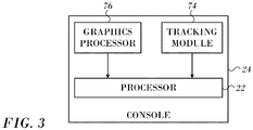
- Fig. 3 is a block diagram of aspects of the processor 22 in accordance with an embodiment of the invention.
- the processor 22 is located in the console 24 ( Fig. 1 ), but it can be remote or distributed among several sites.
- the processor 22 may use a tracking module, such as tracking module 74, to convert signals from the above-noted location-sensing devices to location coordinates in a 3-dimensional frame of reference defined by the field generating coils 28 ( Fig. 1 ).
- Processor 22 is linked to a graphics processor 76.
- the graphics processor 76 is a parallel processing unit that usually has approximately 2,000 processors.
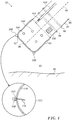
- Fig. 4 is a sectional view along the length of distal segment 78 of a cardiac catheter in accordance with an embodiment of the invention.
- the distal segment 78 is in proximity to tissue 80, and is assumed to be immersed in fluid 82, so that tissue 80 has a surface 29 contacting the fluid.
- Fluid 82 typically comprises a mixture of blood and saline solution.
- distal segment 78 is assumed herein to be formed from an insulating substrate 84 in the shape of a cylinder 86 closed by a generally flat surface 88 at one end.
- Cylinder 86 has an axis of symmetry 90.
- a curved section 92 joins flat surface 88 and cylinder 86.
- a typical diameter of cylinder 86 is 2.5 mm, and a typical radius of the curved section 92 is 0.5 mm.
- Distal segment 78 comprises three electrodes 94, 96, 98, the electrodes being insulated from each other.
- the electrodes 94, 96, 98 typically comprise thin metal layers formed over insulating substrate 84.
- the distal tip has other electrodes, insulated from the electrodes 94, 96, 98, which for simplicity are not shown in the diagram.
- Tip electrode 94 has the shape of a cup with a flat base, and is herein also referred to as the cup electrode.
- Cup electrode 94 typically has a thickness in a range from approximately 0.1 mm to approximately 0.2 30 mm.
- Second and third electrodes 94, 96 are usually in the form of rings, and are also known as ring electrodes.
- Electrodes 94, 96, 98 are connected to a controller in console 24 ( Fig. 1 ) by wires (not shown). At least one of the electrodes is used to ablate tissue 80. Typically, during ablation, heat is generated in the ablating electrode and in the surrounding region. In order to dissipate the heat, small irrigation apertures 100 in the cup electrode. The apertures 100 typically have diameters in an approximate range 0.1 - 0.2 mm. An irrigation tube 102 supplies saline solution to the apertures 100, and the rate of flow of the saline solution through the apertures 100 (causing fluid 82 to be a mixture of blood and saline solution) is controlled by an irrigation module (not shown) in the console 24 ( Fig. 1 ). The saline rate of flow is typically in the range of approximately 2 - 20 cc/minute, but may be higher or lower than this range.
- a saline temperature sensor 104 is located in tube 102, and provides a signal to circuitry in the console 24 ( Fig. 1 ) module 56 enabling the console 24 to measure a temperature of the saline solution input to apertures 100. While the saline solution may be provided at room ambient temperature, e.g., in a range of approximately 19 - 25°C, the solution may be heated slightly during its flow through the catheter, so that the final irrigation temperature may be slightly higher.
- one or more location sensing devices 106 are incorporated in the distal tip. Devices 106 are configured to provide signals to the processor 22 ( Fig. 1 ) enabling the system to ascertain the position and/or orientation of distal segment 78,
- distal segment 78 comprises one or more generally similar temperature sensors 108 (by way of example, two are shown in the diagram), which are fixedly connected, by an insulator, to the outer surface of cup electrode 94, so as to protrude from the surface.
- Sensors 108 have a typical diameter of approximately 0.3 mm and a length of 10 approximately 1.5 mm.
- sensors 108 are thermistors NTC Type AB6, produced by General Electric Company of Schenectady, New York.
- sensors 108 comprise "F" type thermistors produced by Semitec USA Corporation of Torrance, 15 California.
- Curved section 110 of the cup electrode overlays curved section 92 of the 20 distal tip.
- Curved section 110 is in the shape of a partial toroid, typically a partial torus having a tube radius of approximately 0.5 mm.
- a magnified section 112 of Fig. 4 illustrates one of sensors 108 in more detail.
- an insulator 114 separates sensors 108 from curved section 110 of the cup electrode 94.
- Insulator 114 is selected to provide good thermal and electrical insulation, and in some embodiments insulator 114 may comprise an adhesive that bonds sensors 108 to curved section 110.
- Wires 116 connect sensors 108 to the console 24 ( Fig. 1 ).
- the sensors 108 are able to intimately contact tissue 80.
- the processor 22 ( Fig. 1 ) is thus able to use signals from the sensors 108 to provide direct temperature measurements of the tissue 80
- the sensors 108 protrude from the outer surface of the electrode 94 by no more than 0.7 mm, and typically by approximately 0.5 mm.
- tissue contact can be determined using a contact force sensor as described, for example, in commonly assigned U.S. Patent Application Publication No. 20170127974 .
- tissue contact can be determined using impedance-based methods as described U.S. Patent Application Publication Nos. 2008/0288038 and 2008/0275465 , both by Sauarav et al., or using ultrasonic transducers, as described in copending, commonly assigned Application No. 15637191 .
- the methods may be combined with other filters, for example respiratory gating to exclude artefacts.
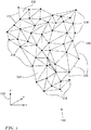
- FIG. 5 is a schematic illustration of points 118 of a mesh in accordance with an embodiment of the invention.
- Points are registered by electrodes 32 ( Fig. 1 ), when in contact with the endocardial surface of the heart 12.
- processor 22 initially stores 3-dimensional coordinates of points 118 as measured in a 3-dimensional frame of reference 120 defined by the field generating coils 28.
- the processor 22 then connects 3-dimensional coordinates of points 118, herein also termed 3-dimensional vertices, by line segments 122 to produce a set of connected 3-dimensional triangles, e.g., triangles 124, 126, 128.
- 3-dimensional coordinates e.g., triangles 124, 126, 128.
- 20150164356 entitled Dynamic Feature Rich Anatomical Reconstruction from a Point Cloud, may be used to produce a mesh 130.
- Other suitable algorithms include the ball-pivoting algorithm to produce the mesh 130.
- a size of the ball is set to correspond to the size of the voxels referred to below.
- the mesh may be generated as a Delaunay triangulation. Elements of the mesh each have 3-dimensional coordinates.
- the triangular mesh 130 models the endocardial surface.
- the processor 22 uses the graphics processor 76 to render the mesh 130 into an image for display on the monitor 29 ( Fig. 1 ).
- realtime positions on the mesh 130 are placed in registration with an image of the heart that was obtained by other modalities, such as computed tomography or magnetic resonance imaging (referred to herein as a "CT/MRI image"). Once this is done points of interest may be transformed from coordinates of the image to coordinates of the mesh 130.
- CT/MRI image computed tomography or magnetic resonance imaging
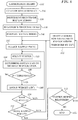
- Fig. 6 is a flow chart of a method of fitting a 3-dimensional model of a heart to a CT/MRI image in accordance with an embodiment of the invention.
- the process steps are shown in a particular linear sequence for clarity of presentation. However, it will be evident that many of them can be performed in parallel, asynchronously, or in different orders. Those skilled in the art will also appreciate that a process could alternatively be represented as a number of interrelated states or events, e.g., in a state diagram. Moreover, not all illustrated process steps may be required to implement the method.
- the algorithm comprises:
- the heart is catheterized conventionally, typically with a multi-electrode mapping catheter, such as a balloon or basket catheter in which the electrodes have known locations on the basket or spline, and have known relationships to one another.
- a multi-electrode mapping catheter such as a balloon or basket catheter in which the electrodes have known locations on the basket or spline, and have known relationships to one another.
- step 134 it is ascertained that the electrodes are in contact with the wall of the heart, using one of the above-described methods.
- current readings are taken at step 136 to determine the locations of the electrodes in current position map in order to construct a current position map that identifies the location of each of the electrodes 32 in the heart.
- One method for generation of a current position map employs the circuitry shown in Fig. 2 . Details are described in the above-noted U.S. Patent No. 8,478,383 .
- step 138 the current position map is placed in registration with a CT/MRI image.
- the CARTOMERGETM module and other facilities of the above-noted CARTO system can accomplish this step using images of the heart prepared at the same or a different session.
- a 3-dimensional model for example the triangular mesh 130 ( Fig. 5 ) is prepared based on the ACL readings and the current position map. This can be accomplished using the teachings of the above-noted U.S. Patent Application Publication No. 20150164356 . Vertices of the matrix are assigned mapping coordinates corresponding to the electrodes of the catheter 14.
- a mesh-fitting algorithm is performed. For each vertex in the mesh all mapped points within a geodesic distance GD are identified and respective weights for the mapped points (1/GD ⁇ 2) assigned with respect to that vertex.
- a mapped point may lie within an influence radius of a more than one vertex, in which case respective weights for the vertices are assigned for that mapped point.
- the vertices are shifted toward mapped points within respective influence radii in accordance with the assigned weights.
- the actual shift of a vertex can be represented as a 3-dimensional vector sum.
- the algorithm is repeated so long as significant changes in the vertices continue to occur, or some other termination criterion is reached.
- a mapped point is selected. All original vertices within a predefined distance, typically 2-15 mm, of the current mapped point will be evaluated in the following steps. "Original vertices" refers to the positions of the vertices at the beginning of the current iteration of the algorithm.
- an original vertex of the mesh 130 is chosen. Then, at step 144 a geodesic distance to the closest corresponding map location (in an appropriately transposed 3-dimensional coordinate system) is determined.
- step 146 it is determined if the distance determined in step 144 is less than the predetermined distance. If the determination at step 144 is affirmative, then control proceeds to step 148. Weights are assigned according to the inverse square of the distance between the vertex and the map location.
- step 150 After performing step 148 or if the determination at decision step 146 is negative, then at decision step 150, it is determined if more vertices need to be adjusted. If the determination at decision step 150 is affirmative, then control returns to step 143 to iterate the loop.
- step 150 determines if more mapped points remain to be evaluated. If the determination at decision step 151 is affirmative, then control returns to step 142.
- vertex shifts are required, i.e., whether the algorithm has converged so that all required shifts are less than some minimal value, or some other termination condition has occurred, e.g., a given number of iterations have been performed.
- step 153 If the determination at decision step 153 is negative then, the procedure ends at final step 152. Otherwise, the calculated shifts are carried out at step 155.
- the mesh 130 is adjusted by shifting the vertices toward the corresponding map locations in accordance with the assigned weights. Control then returns to step 142 to iterate the algorithm using the new mesh positions.
- Fig. 7 is a schematic diagram of a portion of a triangular mesh can be processed in accordance with an embodiment of the invention.
- the mesh as originally constructed in step 140 has vertices 154, 156, 158.
- Mapped points according to the ACL, which has been placed in registration with a CT/MRI image are indicated as points 160, 162, 164, 166.
- the radii of identical circles 168, 170, 172 centered on the vertices 154, 156, 158 represent the maximum distance between the vertices and the mapped points that produce a shift in the vertices.
- Points 162, 164 and vertex 154 lie within circle 172. However, point 162 is closer than point 164 to vertex 154. Accordingly vertex 154 is shifted toward point 162 a distance D1, and vertex 154 assumes a first new position. Point 164 is also within the circle 172. Therefore a new weighting is calculated based on the original distance between the point 164 and vertex 154. A second shift in the direction of point 164 is performed. The final position 174 is equivalent to the sum of weighted vectors directed from vertex 154 toward point 162 and from vertex 154 toward point 164 as indicated by vector diagram 165.
- vertex 156 is therefore not shifted.
- Vertex 158 and point 166 lie within circle 170. It will be noted that point 166 is nearly at the boundary of circle 170, while the point 162 is relatively closer to the vertex 154, being approximately half-way between the vertex 154 and the boundary of circle 172. Vertex 158 is shifted toward point 166 by a distance D2 to a position 176. The distances D1 and D2 are aligned at the left of the figure. It is evident that distance D2 is less that than distance D1.
- the adjusted matrix is indicated by broken lines joining the positions 174, 176 and the vertex 156.
- Fig. 8 and Fig. 9 show a portion of a matrix 178 that simulates a portion of a 3-dimensional surface of a heart in registration with a mapped point 180.
- Vertex 182 is the closest vertex to the mapped point 180.
- Fig. 8 illustrates the relationship between the mapped point 180 and vertex 182 prior to the first vertex shift in step 155 ( Fig. 6 ).
- Fig. 9 shows matrix 178 after performance of step 155 (the effects are intentionally exaggerated for clarity).
- Vertex 182 has now been displaced toward mapped point 180.
- Neighboring vertices 184, 186, 188 are also influenced by proximity to mapped point 180 and hence are displaced toward mapped point 180. The displacements of vertices 184, 186, 188 are less than that of vertex 182, as they are more distant from the mapped point 180, and their assigned weights in step 148 ( Fig. 6 ) are correspondingly lower than that of vertex 182.
- An effect of the displacements is to draw vertices 184, 186, 188 away from vertices that are even more distant from mapped point 180, as evidenced by the difference in relationship between vertex 184 and distant vertex 196 in Fig. 8 and Fig. 9 , and also by distortion of areas 190, 192, 194 in Fig. 9 .
- Vertex 196 is unaffected by mapped point 180 and would be ignored in decision step 146 ( Fig. 6 ).
Description
- This invention relates to image data processing. More particularly, this invention relates to modeling and registration of 3-dimensional images of the heart.
- Medical catheterizations are routinely carried out today, for example, in cases of cardiac arrhythmias, such as atrial fibrillation, which occur when regions of cardiac tissue abnormally conduct electric signals to adjacent tissue, thereby disrupting the normal cardiac cycle and causing asynchronous rhythm. Procedures for treating arrhythmia include surgically disrupting the origin of the signals causing the arrhythmia, as well as disrupting the conducting pathway for such signals. By selectively ablating cardiac tissue by application of energy, e.g., radiofrequency energy via a catheter, it is sometimes possible to cease or modify the propagation of unwanted electrical signals from one portion of the heart to another. The ablation process destroys the unwanted electrical pathways by formation of non-conducting lesions. It is desirable in such procedures to provide a convenient representations of the cardiac anatomy to the operator.
- Catheters containing position sensors may be used to determine the trajectory of points on the cardiac surface. These trajectories may be used to infer motion characteristics such as the contractility of the tissue. As disclosed in
U.S. Pat. No. 5,738,096 , issued to Ben Haim, maps depicting such motion characteristics may be constructed when the trajectory information is sampled at a sufficient number of points in the heart. - Electrical activity at a point in the heart is typically measured by advancing a catheter containing an electrical sensor at or near its distal tip to that point in the heart, contacting the tissue with the sensor and acquiring data at that point. One drawback with mapping a cardiac chamber using a catheter containing only a single, distal tip electrode is the long period of time required to accumulate data on a point-by-point basis over the requisite number of points required for a detailed map of the chamber as a whole. Accordingly, multiple-electrode catheters have been developed to simultaneously measure electrical activity, such as local activation times (LAT) at multiple sampled points in the heart chamber.
- For example, commonly assigned
U.S. Patent Application Publication No. 2017/0103570 to Zar et al. , discloses 3-dimensional cardiac reconstruction is carried out by catheterizing a heart using a probe with a mapping electrode, and acquiring electrical data from respective locations in regionsof interest in the heart, representing the locations of the electrical data as a point cloud, reconstructing a model of the heart from the point cloud, applying a set of filters to the model to produce a filtered volume, segmenting the filtered volume to define components of the heart, and reporting the segmented filtered volume. -
U.S. Patent No. 8,428,700 to Harley et al. , proposes generating an electroanatomic representation of a patient's heart based on the signals measured at the electrodes and information about the positions of the electrodes. The method includes performing a catheter registration procedure with other imaging modalities, such as MRI, annotating the measured signals, and adjusting the annotations for other measured signals in spatial proximity to the specified measured signal. - Martino Alessandrini et al's" An Automatic Framework for the Non-rigid Alignment of Electroanatomical Maps and Preoperative Anatomical Scans in Atrial Fibrillation" (2016 Computing in Cardiology Conference, vol. 43, XP055541776, ISSN: 2325-887X) discloses a framework for the non-rigid alignment of electro-anatomical maps (EAMs) and anatomical scans. In particular, data included, for each patient, one pre-operative magnetic resonance angiography (MRA) scan (average pixel spacing 0.7 x 0/7 mm, slice spacing 1.5 mm) and one electro anatomical map acquired during the ablation procedure. The EAM was provided as a triangular surface mesh. The two geometries were first aligned rigidly by using Procrustes analysis and five anatomical landmarks as control points. The transformation was then finalized by matching the full surfaces. Five techniques for point-cloud registration were contrasted.
- A typical catheterization session involves registration of a scanned CT/MRI image with a 3-dimensional electroanatomic map. However, after registration there are still differences between the CT/MRI image and the real time anatomy determined in a current position map. During the procedure real-time catheter positions are established, and it is verified that the catheter electrodes are in contact with the heart wall, for example by a force threshold measurement or by tissue proximity indications. The current position map is registered with a CT/MRI image.
- A mesh fitting algorithm to identify and resolve the differences in real-time. A 3-dimensional matrix is constructed to model the current position map. Points on the matrix are then adjusted to more closely approximate points on the current position map.
- There is provided according to embodiments of the invention an apparatus, including a multi-electrode probe adapted for insertion into a heart of a living subject, and a processor, which is configured to receive an electrical signal from the electrodes and an acquired image of the heart and to perform the steps of: constructing a position map of the electrodes, simulating a 3-dimensional surface of the heart, placing the position map in registration with acquired image of the heart, constructing, based on the position map, a mesh that models the 3-dimensional surface of the heart, and adjusting positions of vertices of the mesh relative to mapped points on the position map to improve a registration of the mesh with the acquired image. Adjusting positions of the vertices comprises the steps of identifying all vertices of the mesh that are within a predetermined distance from a selected mapped point; calculating respective weight factors based on distances between the identified vertices and the selected mapped point; calculating new positions for the identified vertices comprising a shift toward the selected mapped point according to the respective weight factors; and defining a new mesh based on the new positions.
- There is further provided according to embodiments of the invention a computer software product including a non-transitory computer-readable storage medium in which computer program instructions are stored, which instructions, when executed by a computer, cause the computer to perform the steps of: receiving an electrical signal from a plurality of electrodes in a heart and an acquired image of the heart, constructing a position map of the electrodes, simulating a 3-dimensional surface of the heart, placing the position map in registration with the acquired image of the heart, constructing, based on the position map, a mesh that models the 3-dimensional surface of the heart, and adjusting positions of vertices of the mesh relative to mapped points on the position map to improve a registration of the mesh with the acquired image. Adjusting positions of the vertices comprises the steps of identifying all vertices of the mesh that are within a predetermined distance from a selected mapped point; calculating respective weight factors based on distances between the identified vertices and the selected mapped point; calculating new positions for the identified vertices comprising a shift toward the selected mapped point according to the respective weight factors; and defining a new mesh based on the new positions.
- For a better understanding of the present invention, reference is made to the detailed description of the invention, by way of example, which is to be read in conjunction with the following drawings, wherein like elements are given like reference numerals, and wherein:
-
Fig. 1 is a pictorial illustration of a system for evaluating electrical activity in a heart of a living subject in accordance with an embodiment of the invention; -
Fig. 2 is a schematic diagram of an ablation and active current location (ACL) circuit in accordance with an embodiment of the invention; -
Fig. 3 is a block diagram of aspects of a processor in accordance with an embodiment of the invention; -
Fig. 4 is a sectional view along the length of the distal segment of a cardiac catheter, in accordance with an embodiment of the invention; -
Fig. 5 is a schematic illustration of a mesh in accordance with an embodiment of the invention; -
Fig. 6 is a flow chart of a method of fitting a 3-dimensional model of a heart to a CT/MRI image in accordance with an embodiment of the invention; -
Fig. 7 is a schematic diagram of a portion of a triangular mesh can be processed in accordance with an embodiment of the invention; -
Fig. 8 shows a simulated matrix in registration with a mapped point in accordance with an embodiment of the invention; and -
Fig. 9 shows the matrix ofFig. 8 following a displacement of vertices in accordance with an embodiment of the invention. - In the following description, numerous specific details are set forth in order to provide a thorough understanding of the various principles of the present invention. It will be apparent to one skilled in the art, however, that not all these details are necessarily needed for practicing the present invention. In this instance, well-known circuits, control logic, and the details of computer program instructions for conventional algorithms and processes have not been shown in detail in order not to obscure the general concepts unnecessarily.
- Turning now to the drawings, reference is initially made to
Fig. 1 , which is a pictorial illustration of asystem 10 for performing diagnostic and therapeutic procedures on aheart 12 of a living subject, which is constructed and operative in accordance with a disclosed embodiment of the invention. The system comprises acatheter 14, which is percutaneously inserted by anoperator 16 through the patient's vascular system into a chamber or vascular structure of theheart 12. Theoperator 16, who is typically a physician, brings the catheter'sdistal tip 18 into contact with the heart wall, for example, at an ablation target site. Electrical activation maps may be prepared, according to the methods disclosed inU.S. Patent Nos. 6,226,542 , and6,301,496 , and in commonly assignedU.S. Patent No. 6,892,091 . - The
system 10 may comprise a general purpose or embedded computer processor, which is programmed with suitable software for carrying out the functions described hereinbelow. Thus, although portions of thesystem 10 shown in other drawing figures herein are shown as comprising a number of separate functional blocks, these blocks are not necessarily separate physical entities, but rather may represent, for example, different computing tasks or data objects stored in a memory that is accessible to the processor. These tasks may be carried out in software running on a single processor, or on multiple processors. The software may be provided to the processor or processors on tangible non-transitory media, such as CD-ROM or non-volatile memory. Alternatively or additionally, thesystem 10 may comprise a digital signal processor or hard-wired logic. One commercial product embodying elements of thesystem 10 is available as the CARTO® 3 System, available from Biosense Webster, Inc., 3333 Diamond Canyon Road, Diamond Bar, CA 91765. This system may be modified by those skilled in the art to embody the principles of the invention described herein. - Areas determined to be abnormal, for example by evaluation of the electrical activation maps, can be ablated by application of thermal energy, e.g., by passage of radiofrequency electrical current through wires in the catheter to one or more electrodes at the
distal tip 18, which apply the radiofrequency energy to the myocardium. The energy is absorbed in the tissue, heating it to a point (typically above 50°C) at which it permanently loses its electrical excitability. When successful, this procedure creates non-conducting lesions in the cardiac tissue, which disrupt the abnormal electrical pathway causing the arrhythmia. The principles of the invention can be applied to different heart chambers to diagnose and treat many different cardiac arrhythmias. - The
catheter 14 typically comprises ahandle 20, having suitable controls on the handle to enable theoperator 16 to steer, position and orient the distal end of the catheter as desired for the ablation. To aid theoperator 16, the distal portion of thecatheter 14 contains position sensors (not shown) that provide signals to aprocessor 22, located in aconsole 24. Theprocessor 22 may fulfill several processing functions as described below. - The
catheter 14 is a multi-electrode catheter, which can be a balloon or basket catheter as shown in the right portion ofballoon 37, or a spline catheter as shown in the left portion. In any case there aremultiple electrodes 32, which are used as sensing electrodes and have known locations on the basket or spline, and known relationships to one another. Thus, once the catheter is located in the heart, for example by constructing a current position map, the location of each of theelectrodes 32 in the heart is known. One method for generation of a current position map is described in commonly assignedU.S. Patent No. 8,478,383 to Bar-Tal et al. . - Electrical signals can be conveyed to and from the
heart 12 from theelectrodes 32 located at or near thedistal tip 18 of thecatheter 14 via cable 34 to theconsole 24. Pacing signals and other control signals may be conveyed from theconsole 24 through the cable 34 and theelectrodes 32 to theheart 12. -
Wire connections 35 link theconsole 24 withbody surface electrodes 30 and other components of a positioning sub-system for measuring location and orientation coordinates of thecatheter 14. Theprocessor 22 or another processor (not shown) may be an element of the positioning subsystem. Theelectrodes 32 and thebody surface electrodes 30 may be used to measure tissue impedance at the ablation site as taught inU.S. Patent No. 7,536,218, issued to Govari et al. . A temperature sensor (not shown), typically a thermocouple or thermistor, may be mounted near thedistal tip 18 of thecatheter 14. - The
console 24 typically contains one or moreablation power generators 25. Thecatheter 14 may be adapted to conduct ablative energy to the heart using any known ablation technique, e.g., radiofrequency energy, ultrasound energy, and laser-produced light energy. Such methods are disclosed in commonly assignedU.S. Patent Nos. 6,814,733 ,6,997,924 , and7,156,816 . - In one embodiment, the positioning subsystem comprises a magnetic position tracking arrangement that determines the position and orientation of the
catheter 14 by generating magnetic fields in a predefined working volume and sensing these fields at the catheter, using field generating coils 28. A suitable positioning subsystem is described inU.S. Patent No. 7,756,576 and in the above-notedU.S. Patent No. 7,536,218 . - As noted above, the
catheter 14 is coupled to theconsole 24, which enables theoperator 16 to observe and regulate the functions of thecatheter 14.Console 24 includes a processor, preferably a computer with appropriate signal processing circuits. The processor is coupled to drive amonitor 29. The signal processing circuits typically receive, amplify, filter and digitize signals from thecatheter 14, including signals generated by the above-noted sensors and a plurality of location sensing electrodes (not shown) located distally in thecatheter 14. The digitized signals are received and used by theconsole 24 and the positioning system to compute the position and orientation of thecatheter 14 and to analyze the electrical signals from the electrodes as described in further detail below. - Typically, the
system 10 includes other elements, which are not shown in the figures for the sake of simplicity. For example, thesystem 10 may include an electrocardiogram (ECG) monitor, coupled to receive signals from one or more body surface electrodes, so as to provide an ECG synchronization signal to theconsole 24. As mentioned above, thesystem 10 typically also includes a reference position sensor, either on an externally applied reference patch attached to the exterior of the subject's body, or on an internally-placed catheter, which is inserted into theheart 12 and maintained in a fixed position relative to theheart 12. Thesystem 10 may receive image data from an external imaging modality, such as an MRI unit or the like and includes image processors that can be incorporated in or invoked by theprocessor 22 for generating and displaying images. - Reference is now made to
Fig. 2 , which is a schematic diagram of an ablation and active current location (ACL) circuit for use with the system shown inFig. 1 . This arrangement is similar to that described inU.S. Patent Application Publications 2006/0173251, to Govari et al. , and2007/0038078, to Osadchy . The arrangement can be modified to operate in accordance with the principles of the present invention. A brief description follows for convenience of presentation. - A plurality of
body surface electrodes 42, which can be adhesive skin patches, are coupled to a body surface 44 (e.g., the skin) ofsubject 46. Thebody surface electrodes 42 are sometimes referred to herein as "patches". In cardiac applications thebody surface electrodes 42 are usually distributed so as to surround the heart, three on the chest of the subject and three on the back. However, the number of thebody surface electrodes 42 is not critical, and they may be placed at convenient locations on thebody surface 44 in the general vicinity of the site of the medical procedure. - A
control unit 48, normally disposed in the console 24 (Fig. 1 ), includescurrent measurement circuitry 50 and one or morecatheter electrode transmitters 52 for driving a current through one or more of theelectrodes 42 to one or more of thebody surface electrodes 42 at respective working frequencies. Thecontrol unit 48 is linked to a positioning processor (Fig. 1 ). Thecontrol unit 48 is linked to anablator 54, which comprises at least oneablation generator 56. Currents through thebody surface electrodes 42 and an ablatorbody surface electrode 58 flow in a circuit with theablation generator 56 and are measured by respective current measurement circuits that are disposed withinbody electrode receivers 60, sometimes referred to herein as "patch measurement circuits". Thebody electrode receivers 60 are typically incorporated in thecontrol unit 48. Alternatively, they may be affixed to thebody surface electrodes 42. Catheter electrodes are represented as measurement electrodes 62 (circles) and a dual-purpose electrode 64 (ellipse). The dual-purpose electrode 64 functions as an ablation electrode and also serves as one of the measurement electrodes. - The
body surface electrodes 42 are connected to thebody electrode receivers 60 via apatch box 66, which protects the system from ablation and defibrillation currents. Typically the system is configured with sixbody electrode receivers 60. The patch box parasitic impedances 68 (Z), are measured during production and thus known a priori. These impedances are discussed below. - Typically, although only two
measurement electrodes 62 are shown for convenience, about 80 measurement electrodes are used for impedance measurements. Typically there are one or two ablation electrodes. The coordinates of a catheter inside the body are determined in the positioning system by passing currents between electrodes on the catheter and thebody surface electrodes 42. - The
control unit 48 may also control an ablation circuit, comprisingablator 54, and the dual-purpose electrode 64. Theablator 54 is typically disposed externally to thecontrol unit 48 and incorporates theablation generator 56. It connects with the ablatorbody surface electrode 58 and to an ablator filter 70, which in this example is shown within thecontrol unit 48. However this location is not essential. Aswitch 72 configures the ablator circuit for different modes of operation as described below. Voltage measurement circuitry is provided for determining the output of thecatheter electrode transmitters 52. It will be noted from inspection that the ablation circuit is connected to one of thecatheter electrode transmitters 52. - Reference is now made to
Fig. 3 , which is a block diagram of aspects of theprocessor 22 in accordance with an embodiment of the invention. Typically theprocessor 22 is located in the console 24 (Fig. 1 ), but it can be remote or distributed among several sites. Theprocessor 22 may use a tracking module, such astracking module 74, to convert signals from the above-noted location-sensing devices to location coordinates in a 3-dimensional frame of reference defined by the field generating coils 28 (Fig. 1 ).Processor 22 is linked to agraphics processor 76. Thegraphics processor 76 is a parallel processing unit that usually has approximately 2,000 processors. - In order determine the location of the electrodes with respect to the wall of the heart, it is necessary to ascertain tissue contact. One useful technique is a thermometry-based method as shown in
Fig. 4 , which is a sectional view along the length ofdistal segment 78 of a cardiac catheter in accordance with an embodiment of the invention. Thedistal segment 78 is in proximity totissue 80, and is assumed to be immersed influid 82, so thattissue 80 has asurface 29 contacting the fluid.Fluid 82 typically comprises a mixture of blood and saline solution. By way of example,distal segment 78 is assumed herein to be formed from an insulatingsubstrate 84 in the shape of acylinder 86 closed by a generallyflat surface 88 at one end.Cylinder 86 has an axis ofsymmetry 90. Acurved section 92 joinsflat surface 88 andcylinder 86. A typical diameter ofcylinder 86 is 2.5 mm, and a typical radius of thecurved section 92 is 0.5 mm. -
Distal segment 78 comprises threeelectrodes electrodes substrate 84. Typically, the distal tip has other electrodes, insulated from theelectrodes Tip electrode 94 has the shape of a cup with a flat base, and is herein also referred to as the cup electrode.Cup electrode 94 typically has a thickness in a range from approximately 0.1 mm to approximately 0.2 30 mm. Second andthird electrodes -
Electrodes Fig. 1 ) by wires (not shown). At least one of the electrodes is used to ablatetissue 80. Typically, during ablation, heat is generated in the ablating electrode and in the surrounding region. In order to dissipate the heat,small irrigation apertures 100 in the cup electrode. Theapertures 100 typically have diameters in an approximate range 0.1 - 0.2 mm. Anirrigation tube 102 supplies saline solution to theapertures 100, and the rate of flow of the saline solution through the apertures 100 (causingfluid 82 to be a mixture of blood and saline solution) is controlled by an irrigation module (not shown) in the console 24 (Fig. 1 ). The saline rate of flow is typically in the range of approximately 2 - 20 cc/minute, but may be higher or lower than this range. - A
saline temperature sensor 104, typically a thermocouple, is located intube 102, and provides a signal to circuitry in the console 24 (Fig. 1 )module 56 enabling theconsole 24 to measure a temperature of the saline solution input to apertures 100. While the saline solution may be provided at room ambient temperature, e.g., in a range of approximately 19 - 25°C, the solution may be heated slightly during its flow through the catheter, so that the final irrigation temperature may be slightly higher. - Typically, one or more
location sensing devices 106 are incorporated in the distal tip.Devices 106 are configured to provide signals to the processor 22 (Fig. 1 ) enabling the system to ascertain the position and/or orientation ofdistal segment 78, - In one embodiment
distal segment 78 comprises one or more generally similar temperature sensors 108 (by way of example, two are shown in the diagram), which are fixedly connected, by an insulator, to the outer surface ofcup electrode 94, so as to protrude from the surface.Sensors 108 have a typical diameter of approximately 0.3 mm and a length of 10 approximately 1.5 mm. In oneembodiment sensors 108 are thermistors NTC Type AB6, produced by General Electric Company of Schenectady, New York. In an alternative embodiment,sensors 108 comprise "F" type thermistors produced by Semitec USA Corporation of Torrance, 15 California. By way of example, the following description assumes there are threesensors 108 symmetrically distributed with respect to axis 51, and located on acurved section 110 of the cup electrode.Curved section 110 of the cup electrode overlayscurved section 92 of the 20 distal tip.Curved section 110 is in the shape of a partial toroid, typically a partial torus having a tube radius of approximately 0.5 mm. - A magnified
section 112 ofFig. 4 illustrates one ofsensors 108 in more detail. As shown insection 112, aninsulator 114separates sensors 108 fromcurved section 110 of thecup electrode 94.Insulator 114 is selected to provide good thermal and electrical insulation, and in some embodiments insulator 114 may comprise an adhesive that bondssensors 108 tocurved section 110.Wires 116 connectsensors 108 to the console 24 (Fig. 1 ). - By having
sensors 108 protrude from the outer surface ofcup electrode 94, thesensors 108 are able to intimately contacttissue 80. The processor 22 (Fig. 1 ) is thus able to use signals from thesensors 108 to provide direct temperature measurements of thetissue 80 In one embodiment thesensors 108 protrude from the outer surface of theelectrode 94 by no more than 0.7 mm, and typically by approximately 0.5 mm. - Additional details of thermometry based determination of tissue contact are found in commonly assigned
U.S. Patent Application Publication No. 20170079738 . Alternatively, tissue contact can be determined using a contact force sensor as described, for example, in commonly assignedU.S. Patent Application Publication No. 20170127974 . Further alternatively tissue contact can be determined using impedance-based methods as describedU.S. Patent Application Publication Nos. 2008/0288038 and2008/0275465 , both by Sauarav et al., or using ultrasonic transducers, as described in copending, commonly assigned Application No.15637191 - Reference is now made to
Fig. 5 , which is a schematic illustration ofpoints 118 of a mesh in accordance with an embodiment of the invention. Points are registered by electrodes 32 (Fig. 1 ), when in contact with the endocardial surface of theheart 12. Typically during the mapping referred to above,processor 22 initially stores 3-dimensional coordinates ofpoints 118 as measured in a 3-dimensional frame ofreference 120 defined by the field generating coils 28. Theprocessor 22 then connects 3-dimensional coordinates ofpoints 118, herein also termed 3-dimensional vertices, byline segments 122 to produce a set of connected 3-dimensional triangles, e.g.,triangles U.S. Patent Application Publication No. 20150164356 , entitled Dynamic Feature Rich Anatomical Reconstruction from a Point Cloud, may be used to produce amesh 130. Other suitable algorithms include the ball-pivoting algorithm to produce themesh 130. Typically, if the ball-pivoting algorithm is used, a size of the ball is set to correspond to the size of the voxels referred to below. Alternatively, the mesh may be generated as a Delaunay triangulation. Elements of the mesh each have 3-dimensional coordinates. - In one application the
triangular mesh 130 models the endocardial surface. The processor 22 (Fig. 3 ) uses thegraphics processor 76 to render themesh 130 into an image for display on the monitor 29 (Fig. 1 ). - Initially, realtime positions on the
mesh 130 are placed in registration with an image of the heart that was obtained by other modalities, such as computed tomography or magnetic resonance imaging (referred to herein as a "CT/MRI image"). Once this is done points of interest may be transformed from coordinates of the image to coordinates of themesh 130. - Nevertheless, residual differences between the CT/MRI image and the mesh remain after the registration procedure. These differences are reduced according to embodiments of the invention. Reference is now made to
Fig. 6 , which is a flow chart of a method of fitting a 3-dimensional model of a heart to a CT/MRI image in accordance with an embodiment of the invention. The process steps are shown in a particular linear sequence for clarity of presentation. However, it will be evident that many of them can be performed in parallel, asynchronously, or in different orders. Those skilled in the art will also appreciate that a process could alternatively be represented as a number of interrelated states or events, e.g., in a state diagram. Moreover, not all illustrated process steps may be required to implement the method. The algorithm comprises: - For each mapped point, preferably filtered by cardiorespiratory gating:
- 1. Identify all the vertices in the original mesh that are within a specified radius from the filtered point.
- 2. For each identified vertex calculate a weight factor based on its distance to the filtered point. In one embodiment the weight factor is the inverse square of the distance
- 3. Shift each identified vertex towards the filtered point by the weight calculated in step 2.
- At
initial step 132 the heart is catheterized conventionally, typically with a multi-electrode mapping catheter, such as a balloon or basket catheter in which the electrodes have known locations on the basket or spline, and have known relationships to one another. - Next, at
step 134 it is ascertained that the electrodes are in contact with the wall of the heart, using one of the above-described methods. After completion ofstep 134 current readings are taken atstep 136 to determine the locations of the electrodes in current position map in order to construct a current position map that identifies the location of each of theelectrodes 32 in the heart. One method for generation of a current position map employs the circuitry shown inFig. 2 . Details are described in the above-notedU.S. Patent No. 8,478,383 . - Next, at
step 138 the current position map is placed in registration with a CT/MRI image. The teachings ofU.S. Patent Nos. 7517318 and8320711 and inU.S. Patent Application Publication No. 20160120426 , all of which are commonly assigned, may be used to accomplish this step. Alternatively, the CARTOMERGE™ module and other facilities of the above-noted CARTO system can accomplish this step using images of the heart prepared at the same or a different session. - Next, at step 140 a 3-dimensional model, for example the triangular mesh 130 (
Fig. 5 ), is prepared based on the ACL readings and the current position map. This can be accomplished using the teachings of the above-notedU.S. Patent Application Publication No. 20150164356 . Vertices of the matrix are assigned mapping coordinates corresponding to the electrodes of thecatheter 14. - Next a mesh-fitting algorithm is performed. For each vertex in the mesh all mapped points within a geodesic distance GD are identified and respective weights for the mapped points (1/GD^2) assigned with respect to that vertex. A mapped point may lie within an influence radius of a more than one vertex, in which case respective weights for the vertices are assigned for that mapped point. The vertices are shifted toward mapped points within respective influence radii in accordance with the assigned weights. The actual shift of a vertex can be represented as a 3-dimensional vector sum.
- The algorithm is repeated so long as significant changes in the vertices continue to occur, or some other termination criterion is reached.
- At step 142 a mapped point is selected. All original vertices within a predefined distance, typically 2-15 mm, of the current mapped point will be evaluated in the following steps. "Original vertices" refers to the positions of the vertices at the beginning of the current iteration of the algorithm.
- At
step 143 an original vertex of themesh 130 is chosen. Then, at step 144 a geodesic distance to the closest corresponding map location (in an appropriately transposed 3-dimensional coordinate system) is determined. - Next, at
decision step 146, it is determined if the distance determined instep 144 is less than the predetermined distance. If the determination atstep 144 is affirmative, then control proceeds to step 148. Weights are assigned according to the inverse square of the distance between the vertex and the map location. - After performing
step 148 or if the determination atdecision step 146 is negative, then atdecision step 150, it is determined if more vertices need to be adjusted. If the determination atdecision step 150 is affirmative, then control returns to step 143 to iterate the loop. - If the determination at
decision step 150 is negative then, atdecision step 151 it is determined if more mapped points remain to be evaluated. If the determination atdecision step 151 is affirmative, then control returns to step 142. - If the determination at
decision step 151 is negative, then atdecision step 153 it is determined if vertex shifts are required, i.e., whether the algorithm has converged so that all required shifts are less than some minimal value, or some other termination condition has occurred, e.g., a given number of iterations have been performed. - If the determination at
decision step 153 is negative then, the procedure ends atfinal step 152. Otherwise, the calculated shifts are carried out atstep 155. Themesh 130 is adjusted by shifting the vertices toward the corresponding map locations in accordance with the assigned weights. Control then returns to step 142 to iterate the algorithm using the new mesh positions. - Reference is now made to
Fig. 7 , which is a schematic diagram of a portion of a triangular mesh can be processed in accordance with an embodiment of the invention. The mesh as originally constructed in step 140 (Fig. 6 ) hasvertices points identical circles vertices -
Points vertex 154 lie withincircle 172. However,point 162 is closer thanpoint 164 tovertex 154. Accordinglyvertex 154 is shifted toward point 162 a distance D1, andvertex 154 assumes a first new position.Point 164 is also within thecircle 172. Therefore a new weighting is calculated based on the original distance between thepoint 164 andvertex 154. A second shift in the direction ofpoint 164 is performed. Thefinal position 174 is equivalent to the sum of weighted vectors directed fromvertex 154 towardpoint 162 and fromvertex 154 towardpoint 164 as indicated by vector diagram 165. - The distance between
vertex 156 and the closest mappedpoint 160 exceeds the radius ofcircle 168.Vertex 156 is therefore not shifted. - Vertex 158 and
point 166 lie withincircle 170. It will be noted thatpoint 166 is nearly at the boundary ofcircle 170, while thepoint 162 is relatively closer to thevertex 154, being approximately half-way between thevertex 154 and the boundary ofcircle 172. Vertex 158 is shifted towardpoint 166 by a distance D2 to aposition 176. The distances D1 and D2 are aligned at the left of the figure. It is evident that distance D2 is less that than distance D1. - The adjusted matrix is indicated by broken lines joining the
positions vertex 156. - It will be apparent that when a vertex is shifted, its neighbors are also affected. This effect can be seen in
Fig. 8 and Fig. 9 , which show a portion of amatrix 178 that simulates a portion of a 3-dimensional surface of a heart in registration with a mappedpoint 180.Vertex 182 is the closest vertex to the mappedpoint 180. -
Fig. 8 illustrates the relationship between the mappedpoint 180 andvertex 182 prior to the first vertex shift in step 155 (Fig. 6 ).Fig. 9 showsmatrix 178 after performance of step 155 (the effects are intentionally exaggerated for clarity).Vertex 182 has now been displaced toward mappedpoint 180. Neighboringvertices point 180 and hence are displaced toward mappedpoint 180. The displacements ofvertices vertex 182, as they are more distant from the mappedpoint 180, and their assigned weights in step 148 (Fig. 6 ) are correspondingly lower than that ofvertex 182. - An effect of the displacements is to draw
vertices point 180, as evidenced by the difference in relationship betweenvertex 184 anddistant vertex 196 inFig. 8 and Fig. 9 , and also by distortion ofareas Fig. 9 .Vertex 196 is unaffected by mappedpoint 180 and would be ignored in decision step 146 (Fig. 6 ).
Claims (10)
- An apparatus, comprising:a probe (14) having a plurality ofelectrodes (32) and adapted for insertion into a heart of a living subject; anda processor (22), which is configured to receive an electrical signal from the electrodes (32), and to receive an acquired image of the heart and to perform the steps of:constructing a position map of the electrodes (32), the position map having mapped points and simulating a 3-dimensional surface of the heart;placing the position map in registration with the acquired image of the heart;constructing, based on the position map, a mesh (130) that models the 3-dimensional surface of the heart, the mesh (130) having vertices; andadjusting positions of the vertices (154, 156, 158) relative to the mapped points (160, 162, 164, 166) to improve a registration of the mesh (130) with the acquired image of the heart; wherein adjusting positions of the vertices comprises the steps of:identifying all vertices of the mesh (130) that are within a predetermined distance from a selected mapped point;calculating respective weight factors based on distances between the identified vertices and the selected mapped point;calculating new positions for the identified vertices comprising a shift toward the selected mapped point according to the respective weight factors; anddefining a new mesh based on the new positions.
- The apparatus according to claim 1, wherein the mesh (130) is a triangular matrix.
- The apparatus according to claim 1, wherein the respective weight factors are calculated according to an inverse square of the distances between the identified vertices and the selected mapped point.
- The apparatus according to claim 1, wherein the new positions are determined as vector sums of shifts toward respective mapped points determined in performances of the steps of identifying all vertices and calculating new positions.
- The apparatus according to claim 1, wherein the distances between the identified vertices and the selected mapped point are geodesic distances.
- A computer software product including a non-transitory computer-readable storage medium in which computer program instructions are stored, which instructions, when executed by a computer, cause the computer to perform the steps of:receiving an electrical signal from a plurality of electrodes (32) in a heart;receiving an acquired image of the heart and to perform the steps of:constructing a position map of the electrodes (32), the position map having mapped points and simulating a 3-dimensional surface of the heart;placing the position map in registration with the acquired image of the heart;constructing, based on the position map, a mesh (130) that models the 3-dimensional surface of the heart, the mesh (130) having vertices; andadjusting positions of the vertices (154, 156, 158) relative to the mapped points (160, 162, 164, 166) to improve a registration of the mesh (130) with the acquired image of the heart; wherein adjusting positions of the vertices comprises the steps of:identifying all vertices of the mesh that are within a predetermined distance from a selected mapped point;calculating respective weight factors based on distances between the identified vertices and the selected mapped point;calculating new positions for the identified vertices comprising a shift toward the selected mapped point according to the respective weight factors; anddefining a new mesh based on the new positions.
- The computer software product according to claim 6, wherein the mesh (130) is a triangular matrix.
- The computer software product according to claim 6, wherein the respective weight factors are calculated according to an inverse square of the distances between the identified vertices and the selected mapped point.
- The computer software product according to claim 6, wherein the new positions are determined as vector sums of shifts toward respective mapped points determined in performances of the steps of identifying all vertices and calculating new positions.
- The computer software product according to claim 6, wherein the distances between the identified vertices and the selected mapped point are geodesic distances.
Applications Claiming Priority (1)
| Application Number | Priority Date | Filing Date | Title |
|---|---|---|---|
| US15/696,975 US10682181B2 (en) | 2017-09-06 | 2017-09-06 | Methods and systems for modeling and registration of 3-dimensional images of the heart |
Publications (2)
| Publication Number | Publication Date |
|---|---|
| EP3453328A1 EP3453328A1 (en) | 2019-03-13 |
| EP3453328B1 true EP3453328B1 (en) | 2020-12-23 |
Family
ID=63682972
Family Applications (1)
| Application Number | Title | Priority Date | Filing Date |
|---|---|---|---|
| EP18192728.6A Active EP3453328B1 (en) | 2017-09-06 | 2018-09-05 | Mesh fitting algorithm |
Country Status (11)
| Country | Link |
|---|---|
| US (1) | US10682181B2 (en) |
| EP (1) | EP3453328B1 (en) |
| JP (1) | JP7166848B2 (en) |
| KR (1) | KR20190027326A (en) |
| CN (1) | CN109452948B (en) |
| AU (1) | AU2018220134A1 (en) |
| BR (1) | BR102018067920A2 (en) |
| CA (1) | CA3015087A1 (en) |
| IL (1) | IL261386B (en) |
| MX (1) | MX2018010706A (en) |
| RU (1) | RU2018130839A (en) |
Families Citing this family (16)
| Publication number | Priority date | Publication date | Assignee | Title |
|---|---|---|---|---|
| WO2019111180A1 (en) * | 2017-12-05 | 2019-06-13 | Navix International Limited | Electrophysiology procedure without ionizing radiation imaging |
| US11213235B2 (en) * | 2018-12-04 | 2022-01-04 | Biosense Webster (Israel) Ltd. | Coronary sinus (CS) catheter movement detection |
| US11045628B2 (en) | 2018-12-11 | 2021-06-29 | Biosense Webster (Israel) Ltd. | Balloon catheter with high articulation |
| US11510627B2 (en) | 2019-01-15 | 2022-11-29 | Apn Health, Llc | Cardiac catheter contact force determination |
| US11850051B2 (en) | 2019-04-30 | 2023-12-26 | Biosense Webster (Israel) Ltd. | Mapping grid with high density electrode array |
| CN110251225B (en) * | 2019-05-08 | 2020-10-27 | 首都医科大学宣武医院 | Method for establishing three-dimensional cross damage grid and focus damage system |
| US11950930B2 (en) | 2019-12-12 | 2024-04-09 | Biosense Webster (Israel) Ltd. | Multi-dimensional acquisition of bipolar signals from a catheter |
| US11517218B2 (en) | 2019-12-20 | 2022-12-06 | Biosense Webster (Israel) Ltd. | Selective graphical presentation of electrophysiological parameters |
| US11950841B2 (en) | 2020-09-22 | 2024-04-09 | Biosense Webster (Israel) Ltd. | Basket catheter having insulated ablation electrodes and diagnostic electrodes |
| US11950840B2 (en) | 2020-09-22 | 2024-04-09 | Biosense Webster (Israel) Ltd. | Basket catheter having insulated ablation electrodes |
| CN112362732B (en) * | 2020-10-21 | 2023-03-28 | 南京理工大学 | Free-form surface defect detection method and system based on laser ultrasonic elliptical imaging |
| US11321934B1 (en) * | 2020-11-19 | 2022-05-03 | Neucures Inc. | System and method for generating and electro-anatomical map with a user control mechanism to dynamically adjust a color scale associated said map |
| CN112489216B (en) * | 2020-11-27 | 2023-07-28 | 北京百度网讯科技有限公司 | Evaluation method, device and equipment of facial reconstruction model and readable storage medium |
| US11918383B2 (en) | 2020-12-21 | 2024-03-05 | Biosense Webster (Israel) Ltd. | Visualizing performance of catheter electrodes |
| EP4202846A1 (en) * | 2021-12-23 | 2023-06-28 | Koninklijke Philips N.V. | Adaptive 3d modelling of an anatomical cavity |
| KR20230147467A (en) * | 2022-04-14 | 2023-10-23 | 연세대학교 산학협력단 | Apparatus and method for predicting atrial fibrillation recurrence |
Family Cites Families (38)
| Publication number | Priority date | Publication date | Assignee | Title |
|---|---|---|---|---|
| US5738096A (en) | 1993-07-20 | 1998-04-14 | Biosense, Inc. | Cardiac electromechanics |
| US6106466A (en) * | 1997-04-24 | 2000-08-22 | University Of Washington | Automated delineation of heart contours from images using reconstruction-based modeling |
| US6226542B1 (en) * | 1998-07-24 | 2001-05-01 | Biosense, Inc. | Three-dimensional reconstruction of intrabody organs |
| US6301496B1 (en) | 1998-07-24 | 2001-10-09 | Biosense, Inc. | Vector mapping of three-dimensionally reconstructed intrabody organs and method of display |
| US6892091B1 (en) | 2000-02-18 | 2005-05-10 | Biosense, Inc. | Catheter, method and apparatus for generating an electrical map of a chamber of the heart |
| US6650927B1 (en) * | 2000-08-18 | 2003-11-18 | Biosense, Inc. | Rendering of diagnostic imaging data on a three-dimensional map |
| US6814733B2 (en) | 2002-01-31 | 2004-11-09 | Biosense, Inc. | Radio frequency pulmonary vein isolation |
| US6997924B2 (en) | 2002-09-17 | 2006-02-14 | Biosense Inc. | Laser pulmonary vein isolation |
| US7001383B2 (en) * | 2002-10-21 | 2006-02-21 | Biosense, Inc. | Real-time monitoring and mapping of ablation lesion formation in the heart |
| US7156816B2 (en) | 2002-11-26 | 2007-01-02 | Biosense, Inc. | Ultrasound pulmonary vein isolation |
| US7869865B2 (en) | 2005-01-07 | 2011-01-11 | Biosense Webster, Inc. | Current-based position sensing |
| US7715604B2 (en) | 2005-01-18 | 2010-05-11 | Siemens Medical Solutions Usa, Inc. | System and method for automatically registering three dimensional cardiac images with electro-anatomical cardiac mapping data |
| US7517318B2 (en) | 2005-04-26 | 2009-04-14 | Biosense Webster, Inc. | Registration of electro-anatomical map with pre-acquired image using ultrasound |
| US7848787B2 (en) | 2005-07-08 | 2010-12-07 | Biosense Webster, Inc. | Relative impedance measurement |
| US7536218B2 (en) | 2005-07-15 | 2009-05-19 | Biosense Webster, Inc. | Hybrid magnetic-based and impedance-based position sensing |
| US7756576B2 (en) | 2005-08-26 | 2010-07-13 | Biosense Webster, Inc. | Position sensing and detection of skin impedance |
| US20070049817A1 (en) * | 2005-08-30 | 2007-03-01 | Assaf Preiss | Segmentation and registration of multimodal images using physiological data |
| AU2006321918B2 (en) | 2005-12-06 | 2011-08-25 | St. Jude Medical, Atrial Fibrillation Division Inc. | Assessment of electrode coupling for tissue ablation |
| US7855723B2 (en) * | 2006-03-21 | 2010-12-21 | Biosense Webster, Inc. | Image registration using locally-weighted fitting |
| JP4923706B2 (en) * | 2006-04-28 | 2012-04-25 | 三菱電機株式会社 | Topographic data correction apparatus and topographic data correction method |
| CN101443792A (en) * | 2006-05-17 | 2009-05-27 | 圣朱德医疗有限公司房颤分公司 | System and method for mapping electrophysiology information onto complex geometry |
| CA2670261A1 (en) | 2006-11-16 | 2008-05-29 | Vanderbilt University | Apparatus and methods of compensating for organ deformation, registration of internal structures to images, and applications of same |
| US8320711B2 (en) | 2007-12-05 | 2012-11-27 | Biosense Webster, Inc. | Anatomical modeling from a 3-D image and a surface mapping |
| JP5072625B2 (en) * | 2008-01-31 | 2012-11-14 | 株式会社東芝 | Image processing apparatus and method |
| US8819591B2 (en) | 2009-10-30 | 2014-08-26 | Accuray Incorporated | Treatment planning in a virtual environment |
| US8478383B2 (en) | 2010-12-14 | 2013-07-02 | Biosense Webster (Israel), Ltd. | Probe tracking using multiple tracking methods |
| EP2627243B1 (en) * | 2010-12-30 | 2020-01-22 | St. Jude Medical, Atrial Fibrillation Division, Inc. | System for diagnosing arrhythmias and directing catheter therapies |
| US8948837B2 (en) | 2011-01-13 | 2015-02-03 | Rhythmia Medical, Inc. | Electroanatomical mapping |
| US9572535B2 (en) * | 2013-12-05 | 2017-02-21 | Biosense Webster (Israel) Ltd. | Dynamic mapping point filtering using a pre-acquired image |
| US9265434B2 (en) | 2013-12-18 | 2016-02-23 | Biosense Webster (Israel) Ltd. | Dynamic feature rich anatomical reconstruction from a point cloud |
| US10980439B2 (en) * | 2014-08-06 | 2021-04-20 | Biosense Webster (Israel) Ltd | Wavefront analysis based on ablation parameters |
| US9723204B2 (en) * | 2014-08-27 | 2017-08-01 | Adobe Systems Incorporated | Dynamic motion path blur kernel |
| US9955889B2 (en) | 2014-11-03 | 2018-05-01 | Biosense Webster (Israel) Ltd. | Registration maps using intra-cardiac signals |
| US10327859B2 (en) | 2015-09-21 | 2019-06-25 | Biosense Webster (Israel) Ltd. | Catheter stability indication |
| US9875578B2 (en) * | 2015-10-13 | 2018-01-23 | Biosense Webster (Israel) Ltd. | Voxelization of a mesh |
| US10383543B2 (en) | 2015-11-11 | 2019-08-20 | Biosense Webster (Israel) Ltd. | Symmetric short contact force sensor with four coils |
| US10282888B2 (en) | 2016-01-28 | 2019-05-07 | Biosense Webster (Israel) Ltd. | High definition coloring of heart chambers |
| CN105796094B (en) * | 2016-05-13 | 2018-07-06 | 浙江大学 | A kind of extremely exciting independent positioning method of the ventricular premature beat based on ECGI |
-
2017
- 2017-09-06 US US15/696,975 patent/US10682181B2/en active Active
-
2018
- 2018-08-23 CA CA3015087A patent/CA3015087A1/en not_active Abandoned
- 2018-08-24 AU AU2018220134A patent/AU2018220134A1/en not_active Abandoned
- 2018-08-27 IL IL261386A patent/IL261386B/en active IP Right Grant
- 2018-08-27 RU RU2018130839A patent/RU2018130839A/en not_active Application Discontinuation
- 2018-09-04 KR KR1020180105156A patent/KR20190027326A/en not_active Application Discontinuation
- 2018-09-05 JP JP2018165864A patent/JP7166848B2/en active Active
- 2018-09-05 MX MX2018010706A patent/MX2018010706A/en unknown
- 2018-09-05 BR BR102018067920-1A patent/BR102018067920A2/en not_active IP Right Cessation
- 2018-09-05 EP EP18192728.6A patent/EP3453328B1/en active Active
- 2018-09-06 CN CN201811040838.8A patent/CN109452948B/en active Active
Non-Patent Citations (1)
| Title |
|---|
| None * |
Also Published As
| Publication number | Publication date |
|---|---|
| US10682181B2 (en) | 2020-06-16 |
| CN109452948A (en) | 2019-03-12 |
| MX2018010706A (en) | 2019-03-07 |
| CN109452948B (en) | 2024-04-09 |
| BR102018067920A2 (en) | 2019-05-07 |
| IL261386B (en) | 2021-04-29 |
| JP2019042514A (en) | 2019-03-22 |
| CA3015087A1 (en) | 2019-03-06 |
| RU2018130839A (en) | 2020-02-28 |
| JP7166848B2 (en) | 2022-11-08 |
| KR20190027326A (en) | 2019-03-14 |
| IL261386A (en) | 2019-02-28 |
| US20190069954A1 (en) | 2019-03-07 |
| EP3453328A1 (en) | 2019-03-13 |
| AU2018220134A1 (en) | 2019-03-21 |
Similar Documents
| Publication | Publication Date | Title |
|---|---|---|
| EP3453328B1 (en) | Mesh fitting algorithm | |
| US10893820B2 (en) | Registration maps using intra-cardiac signals | |
| CN108074276B (en) | Marking sparse regions on map | |
| US10441188B2 (en) | Automatic display of earliest LAT point | |
| EP3449821B1 (en) | Advanced current location (acl) automatic map rotation to detect holes in current position map (cpm) mapping | |
| CA2987760A1 (en) | Real time electroanatomical coloring of the heart | |
| JP7366535B2 (en) | Graphical user interface (GUI) for displaying the estimated proximity of the cardiac catheter to the esophagus | |
| JP7051291B2 (en) | Device | |
| EP3184070B1 (en) | Global mapping catheter contact optimization | |
| JP2020192325A (en) | Determining occurrence of focal and/or rotor arrhythmogenic activity in cardiac tissue regions | |
| JP6727936B2 (en) | Registration of coronary sinus catheter images | |
| JP7366534B2 (en) | Estimating the proximity of the cardiac catheter to the esophagus | |
| EP4122413A1 (en) | Accurate tissue proximity | |
| US20230404676A1 (en) | Visualizing a quality index indicative of ablation stability at ablation site | |
| JP2023099354A (en) | intuitive mapping system |
Legal Events
| Date | Code | Title | Description |
|---|---|---|---|
| PUAI | Public reference made under article 153(3) epc to a published international application that has entered the european phase |
Free format text: ORIGINAL CODE: 0009012 |
|
| STAA | Information on the status of an ep patent application or granted ep patent |
Free format text: STATUS: THE APPLICATION HAS BEEN PUBLISHED |
|
| AK | Designated contracting states |
Kind code of ref document: A1 Designated state(s): AL AT BE BG CH CY CZ DE DK EE ES FI FR GB GR HR HU IE IS IT LI LT LU LV MC MK MT NL NO PL PT RO RS SE SI SK SM TR |
|
| AX | Request for extension of the european patent |
Extension state: BA ME |
|
| STAA | Information on the status of an ep patent application or granted ep patent |
Free format text: STATUS: REQUEST FOR EXAMINATION WAS MADE |
|
| 17P | Request for examination filed |
Effective date: 20190912 |
|
| RBV | Designated contracting states (corrected) |
Designated state(s): AL AT BE BG CH CY CZ DE DK EE ES FI FR GB GR HR HU IE IS IT LI LT LU LV MC MK MT NL NO PL PT RO RS SE SI SK SM TR |
|
| GRAP | Despatch of communication of intention to grant a patent |
Free format text: ORIGINAL CODE: EPIDOSNIGR1 |
|
| STAA | Information on the status of an ep patent application or granted ep patent |
Free format text: STATUS: GRANT OF PATENT IS INTENDED |
|
| RIC1 | Information provided on ipc code assigned before grant |
Ipc: A61B 6/03 20060101ALN20200608BHEP Ipc: A61B 6/00 20060101AFI20200608BHEP Ipc: A61B 5/042 20060101ALI20200608BHEP Ipc: G06T 7/30 20170101ALI20200608BHEP Ipc: A61B 90/00 20160101ALI20200608BHEP Ipc: A61B 18/14 20060101ALI20200608BHEP |
|
| RIC1 | Information provided on ipc code assigned before grant |
Ipc: A61B 18/14 20060101ALI20200625BHEP Ipc: A61B 90/00 20160101ALI20200625BHEP Ipc: A61B 6/00 20060101AFI20200625BHEP Ipc: G06T 7/30 20170101ALI20200625BHEP Ipc: A61B 5/042 20060101ALI20200625BHEP Ipc: A61B 6/03 20060101ALN20200625BHEP |
|
| INTG | Intention to grant announced |
Effective date: 20200708 |
|
| GRAJ | Information related to disapproval of communication of intention to grant by the applicant or resumption of examination proceedings by the epo deleted |
Free format text: ORIGINAL CODE: EPIDOSDIGR1 |
|
| STAA | Information on the status of an ep patent application or granted ep patent |
Free format text: STATUS: REQUEST FOR EXAMINATION WAS MADE |
|
| GRAP | Despatch of communication of intention to grant a patent |
Free format text: ORIGINAL CODE: EPIDOSNIGR1 |
|
| STAA | Information on the status of an ep patent application or granted ep patent |
Free format text: STATUS: GRANT OF PATENT IS INTENDED |
|
| INTC | Intention to grant announced (deleted) | ||
| INTG | Intention to grant announced |
Effective date: 20200901 |
|
| GRAS | Grant fee paid |
Free format text: ORIGINAL CODE: EPIDOSNIGR3 |
|
| GRAA | (expected) grant |
Free format text: ORIGINAL CODE: 0009210 |
|
| STAA | Information on the status of an ep patent application or granted ep patent |
Free format text: STATUS: THE PATENT HAS BEEN GRANTED |
|
| AK | Designated contracting states |
Kind code of ref document: B1 Designated state(s): AL AT BE BG CH CY CZ DE DK EE ES FI FR GB GR HR HU IE IS IT LI LT LU LV MC MK MT NL NO PL PT RO RS SE SI SK SM TR |
|
| REG | Reference to a national code |
Ref country code: GB Ref legal event code: FG4D |
|
| REG | Reference to a national code |
Ref country code: DE Ref legal event code: R096 Ref document number: 602018011036 Country of ref document: DE |
|
| REG | Reference to a national code |
Ref country code: AT Ref legal event code: REF Ref document number: 1346905 Country of ref document: AT Kind code of ref document: T Effective date: 20210115 |
|
| REG | Reference to a national code |
Ref country code: IE Ref legal event code: FG4D |
|
| REG | Reference to a national code |
Ref country code: NL Ref legal event code: FP |
|
| PG25 | Lapsed in a contracting state [announced via postgrant information from national office to epo] |
Ref country code: GR Free format text: LAPSE BECAUSE OF FAILURE TO SUBMIT A TRANSLATION OF THE DESCRIPTION OR TO PAY THE FEE WITHIN THE PRESCRIBED TIME-LIMIT Effective date: 20210324 Ref country code: NO Free format text: LAPSE BECAUSE OF FAILURE TO SUBMIT A TRANSLATION OF THE DESCRIPTION OR TO PAY THE FEE WITHIN THE PRESCRIBED TIME-LIMIT Effective date: 20210323 Ref country code: FI Free format text: LAPSE BECAUSE OF FAILURE TO SUBMIT A TRANSLATION OF THE DESCRIPTION OR TO PAY THE FEE WITHIN THE PRESCRIBED TIME-LIMIT Effective date: 20201223 Ref country code: RS Free format text: LAPSE BECAUSE OF FAILURE TO SUBMIT A TRANSLATION OF THE DESCRIPTION OR TO PAY THE FEE WITHIN THE PRESCRIBED TIME-LIMIT Effective date: 20201223 |
|
| REG | Reference to a national code |
Ref country code: AT Ref legal event code: MK05 Ref document number: 1346905 Country of ref document: AT Kind code of ref document: T Effective date: 20201223 |
|
| PG25 | Lapsed in a contracting state [announced via postgrant information from national office to epo] |
Ref country code: BG Free format text: LAPSE BECAUSE OF FAILURE TO SUBMIT A TRANSLATION OF THE DESCRIPTION OR TO PAY THE FEE WITHIN THE PRESCRIBED TIME-LIMIT Effective date: 20210323 Ref country code: SE Free format text: LAPSE BECAUSE OF FAILURE TO SUBMIT A TRANSLATION OF THE DESCRIPTION OR TO PAY THE FEE WITHIN THE PRESCRIBED TIME-LIMIT Effective date: 20201223 Ref country code: LV Free format text: LAPSE BECAUSE OF FAILURE TO SUBMIT A TRANSLATION OF THE DESCRIPTION OR TO PAY THE FEE WITHIN THE PRESCRIBED TIME-LIMIT Effective date: 20201223 |
|
| PG25 | Lapsed in a contracting state [announced via postgrant information from national office to epo] |
Ref country code: HR Free format text: LAPSE BECAUSE OF FAILURE TO SUBMIT A TRANSLATION OF THE DESCRIPTION OR TO PAY THE FEE WITHIN THE PRESCRIBED TIME-LIMIT Effective date: 20201223 |
|
| REG | Reference to a national code |
Ref country code: LT Ref legal event code: MG9D |
|
| PG25 | Lapsed in a contracting state [announced via postgrant information from national office to epo] |
Ref country code: PT Free format text: LAPSE BECAUSE OF FAILURE TO SUBMIT A TRANSLATION OF THE DESCRIPTION OR TO PAY THE FEE WITHIN THE PRESCRIBED TIME-LIMIT Effective date: 20210423 Ref country code: SK Free format text: LAPSE BECAUSE OF FAILURE TO SUBMIT A TRANSLATION OF THE DESCRIPTION OR TO PAY THE FEE WITHIN THE PRESCRIBED TIME-LIMIT Effective date: 20201223 Ref country code: RO Free format text: LAPSE BECAUSE OF FAILURE TO SUBMIT A TRANSLATION OF THE DESCRIPTION OR TO PAY THE FEE WITHIN THE PRESCRIBED TIME-LIMIT Effective date: 20201223 Ref country code: LT Free format text: LAPSE BECAUSE OF FAILURE TO SUBMIT A TRANSLATION OF THE DESCRIPTION OR TO PAY THE FEE WITHIN THE PRESCRIBED TIME-LIMIT Effective date: 20201223 Ref country code: SM Free format text: LAPSE BECAUSE OF FAILURE TO SUBMIT A TRANSLATION OF THE DESCRIPTION OR TO PAY THE FEE WITHIN THE PRESCRIBED TIME-LIMIT Effective date: 20201223 Ref country code: EE Free format text: LAPSE BECAUSE OF FAILURE TO SUBMIT A TRANSLATION OF THE DESCRIPTION OR TO PAY THE FEE WITHIN THE PRESCRIBED TIME-LIMIT Effective date: 20201223 Ref country code: CZ Free format text: LAPSE BECAUSE OF FAILURE TO SUBMIT A TRANSLATION OF THE DESCRIPTION OR TO PAY THE FEE WITHIN THE PRESCRIBED TIME-LIMIT Effective date: 20201223 |
|
| PG25 | Lapsed in a contracting state [announced via postgrant information from national office to epo] |
Ref country code: PL Free format text: LAPSE BECAUSE OF FAILURE TO SUBMIT A TRANSLATION OF THE DESCRIPTION OR TO PAY THE FEE WITHIN THE PRESCRIBED TIME-LIMIT Effective date: 20201223 Ref country code: AT Free format text: LAPSE BECAUSE OF FAILURE TO SUBMIT A TRANSLATION OF THE DESCRIPTION OR TO PAY THE FEE WITHIN THE PRESCRIBED TIME-LIMIT Effective date: 20201223 |
|
| REG | Reference to a national code |
Ref country code: DE Ref legal event code: R097 Ref document number: 602018011036 Country of ref document: DE |
|
| PG25 | Lapsed in a contracting state [announced via postgrant information from national office to epo] |
Ref country code: IS Free format text: LAPSE BECAUSE OF FAILURE TO SUBMIT A TRANSLATION OF THE DESCRIPTION OR TO PAY THE FEE WITHIN THE PRESCRIBED TIME-LIMIT Effective date: 20210423 |
|
| PG25 | Lapsed in a contracting state [announced via postgrant information from national office to epo] |
Ref country code: AL Free format text: LAPSE BECAUSE OF FAILURE TO SUBMIT A TRANSLATION OF THE DESCRIPTION OR TO PAY THE FEE WITHIN THE PRESCRIBED TIME-LIMIT Effective date: 20201223 |
|
| PLBE | No opposition filed within time limit |
Free format text: ORIGINAL CODE: 0009261 |
|
| STAA | Information on the status of an ep patent application or granted ep patent |
Free format text: STATUS: NO OPPOSITION FILED WITHIN TIME LIMIT |
|
| PG25 | Lapsed in a contracting state [announced via postgrant information from national office to epo] |
Ref country code: DK Free format text: LAPSE BECAUSE OF FAILURE TO SUBMIT A TRANSLATION OF THE DESCRIPTION OR TO PAY THE FEE WITHIN THE PRESCRIBED TIME-LIMIT Effective date: 20201223 |
|
| 26N | No opposition filed |
Effective date: 20210924 |
|
| PG25 | Lapsed in a contracting state [announced via postgrant information from national office to epo] |
Ref country code: ES Free format text: LAPSE BECAUSE OF FAILURE TO SUBMIT A TRANSLATION OF THE DESCRIPTION OR TO PAY THE FEE WITHIN THE PRESCRIBED TIME-LIMIT Effective date: 20201223 |
|
| PG25 | Lapsed in a contracting state [announced via postgrant information from national office to epo] |
Ref country code: SI Free format text: LAPSE BECAUSE OF FAILURE TO SUBMIT A TRANSLATION OF THE DESCRIPTION OR TO PAY THE FEE WITHIN THE PRESCRIBED TIME-LIMIT Effective date: 20201223 |
|
| REG | Reference to a national code |
Ref country code: CH Ref legal event code: PL |
|
| REG | Reference to a national code |
Ref country code: BE Ref legal event code: MM Effective date: 20210930 |
|
| PG25 | Lapsed in a contracting state [announced via postgrant information from national office to epo] |
Ref country code: IS Free format text: LAPSE BECAUSE OF FAILURE TO SUBMIT A TRANSLATION OF THE DESCRIPTION OR TO PAY THE FEE WITHIN THE PRESCRIBED TIME-LIMIT Effective date: 20210423 Ref country code: MC Free format text: LAPSE BECAUSE OF FAILURE TO SUBMIT A TRANSLATION OF THE DESCRIPTION OR TO PAY THE FEE WITHIN THE PRESCRIBED TIME-LIMIT Effective date: 20201223 |
|
| PG25 | Lapsed in a contracting state [announced via postgrant information from national office to epo] |
Ref country code: LU Free format text: LAPSE BECAUSE OF NON-PAYMENT OF DUE FEES Effective date: 20210905 Ref country code: IE Free format text: LAPSE BECAUSE OF NON-PAYMENT OF DUE FEES Effective date: 20210905 Ref country code: BE Free format text: LAPSE BECAUSE OF NON-PAYMENT OF DUE FEES Effective date: 20210930 |
|
| PG25 | Lapsed in a contracting state [announced via postgrant information from national office to epo] |
Ref country code: LI Free format text: LAPSE BECAUSE OF NON-PAYMENT OF DUE FEES Effective date: 20210930 Ref country code: CH Free format text: LAPSE BECAUSE OF NON-PAYMENT OF DUE FEES Effective date: 20210930 |
|
| PGFP | Annual fee paid to national office [announced via postgrant information from national office to epo] |
Ref country code: NL Payment date: 20220819 Year of fee payment: 5 |
|
| PG25 | Lapsed in a contracting state [announced via postgrant information from national office to epo] |
Ref country code: CY Free format text: LAPSE BECAUSE OF FAILURE TO SUBMIT A TRANSLATION OF THE DESCRIPTION OR TO PAY THE FEE WITHIN THE PRESCRIBED TIME-LIMIT Effective date: 20201223 |
|
| PG25 | Lapsed in a contracting state [announced via postgrant information from national office to epo] |
Ref country code: HU Free format text: LAPSE BECAUSE OF FAILURE TO SUBMIT A TRANSLATION OF THE DESCRIPTION OR TO PAY THE FEE WITHIN THE PRESCRIBED TIME-LIMIT; INVALID AB INITIO Effective date: 20180905 |
|
| PGFP | Annual fee paid to national office [announced via postgrant information from national office to epo] |
Ref country code: IT Payment date: 20230810 Year of fee payment: 6 Ref country code: GB Payment date: 20230803 Year of fee payment: 6 |
|
| PGFP | Annual fee paid to national office [announced via postgrant information from national office to epo] |
Ref country code: FR Payment date: 20230808 Year of fee payment: 6 Ref country code: DE Payment date: 20230802 Year of fee payment: 6 |