EP3451701A1 - Hörgerät mit antenne - Google Patents
Hörgerät mit antenne Download PDFInfo
- Publication number
- EP3451701A1 EP3451701A1 EP17188504.9A EP17188504A EP3451701A1 EP 3451701 A1 EP3451701 A1 EP 3451701A1 EP 17188504 A EP17188504 A EP 17188504A EP 3451701 A1 EP3451701 A1 EP 3451701A1
- Authority
- EP
- European Patent Office
- Prior art keywords
- antenna
- hearing aid
- branch
- antenna branch
- distal end
- Prior art date
- Legal status (The legal status is an assumption and is not a legal conclusion. Google has not performed a legal analysis and makes no representation as to the accuracy of the status listed.)
- Withdrawn
Links
Images


Classifications
-
- H—ELECTRICITY
- H04—ELECTRIC COMMUNICATION TECHNIQUE
- H04R—LOUDSPEAKERS, MICROPHONES, GRAMOPHONE PICK-UPS OR LIKE ACOUSTIC ELECTROMECHANICAL TRANSDUCERS; DEAF-AID SETS; PUBLIC ADDRESS SYSTEMS
- H04R25/00—Deaf-aid sets, i.e. electro-acoustic or electro-mechanical hearing aids; Electric tinnitus maskers providing an auditory perception
- H04R25/55—Deaf-aid sets, i.e. electro-acoustic or electro-mechanical hearing aids; Electric tinnitus maskers providing an auditory perception using an external connection, either wireless or wired
- H04R25/554—Deaf-aid sets, i.e. electro-acoustic or electro-mechanical hearing aids; Electric tinnitus maskers providing an auditory perception using an external connection, either wireless or wired using a wireless connection, e.g. between microphone and amplifier or using Tcoils
-
- H—ELECTRICITY
- H01—ELECTRIC ELEMENTS
- H01Q—ANTENNAS, i.e. RADIO AERIALS
- H01Q1/00—Details of, or arrangements associated with, antennas
- H01Q1/12—Supports; Mounting means
- H01Q1/22—Supports; Mounting means by structural association with other equipment or articles
-
- H—ELECTRICITY
- H01—ELECTRIC ELEMENTS
- H01Q—ANTENNAS, i.e. RADIO AERIALS
- H01Q1/00—Details of, or arrangements associated with, antennas
- H01Q1/27—Adaptation for use in or on movable bodies
- H01Q1/273—Adaptation for carrying or wearing by persons or animals
-
- H—ELECTRICITY
- H01—ELECTRIC ELEMENTS
- H01Q—ANTENNAS, i.e. RADIO AERIALS
- H01Q21/00—Antenna arrays or systems
-
- H—ELECTRICITY
- H01—ELECTRIC ELEMENTS
- H01Q—ANTENNAS, i.e. RADIO AERIALS
- H01Q5/00—Arrangements for simultaneous operation of antennas on two or more different wavebands, e.g. dual-band or multi-band arrangements
- H01Q5/30—Arrangements for providing operation on different wavebands
- H01Q5/307—Individual or coupled radiating elements, each element being fed in an unspecified way
- H01Q5/342—Individual or coupled radiating elements, each element being fed in an unspecified way for different propagation modes
- H01Q5/357—Individual or coupled radiating elements, each element being fed in an unspecified way for different propagation modes using a single feed point
- H01Q5/364—Creating multiple current paths
- H01Q5/371—Branching current paths
-
- H—ELECTRICITY
- H04—ELECTRIC COMMUNICATION TECHNIQUE
- H04R—LOUDSPEAKERS, MICROPHONES, GRAMOPHONE PICK-UPS OR LIKE ACOUSTIC ELECTROMECHANICAL TRANSDUCERS; DEAF-AID SETS; PUBLIC ADDRESS SYSTEMS
- H04R2225/00—Details of deaf aids covered by H04R25/00, not provided for in any of its subgroups
- H04R2225/023—Completely in the canal [CIC] hearing aids
-
- H—ELECTRICITY
- H04—ELECTRIC COMMUNICATION TECHNIQUE
- H04R—LOUDSPEAKERS, MICROPHONES, GRAMOPHONE PICK-UPS OR LIKE ACOUSTIC ELECTROMECHANICAL TRANSDUCERS; DEAF-AID SETS; PUBLIC ADDRESS SYSTEMS
- H04R2225/00—Details of deaf aids covered by H04R25/00, not provided for in any of its subgroups
- H04R2225/025—In the ear hearing aids [ITE] hearing aids
-
- H—ELECTRICITY
- H04—ELECTRIC COMMUNICATION TECHNIQUE
- H04R—LOUDSPEAKERS, MICROPHONES, GRAMOPHONE PICK-UPS OR LIKE ACOUSTIC ELECTROMECHANICAL TRANSDUCERS; DEAF-AID SETS; PUBLIC ADDRESS SYSTEMS
- H04R2225/00—Details of deaf aids covered by H04R25/00, not provided for in any of its subgroups
- H04R2225/51—Aspects of antennas or their circuitry in or for hearing aids
Definitions
- the present disclosure relates to a hearing aid having an antenna that provides the hearing aid with wireless communication capabilities.
- Hearing aids are very delicate devices and comprise many mechanic and electronic components. This presents considerable challenges for hearing aid developers. Developing miniature hearing aids that are completely wearable in the ear, e.g. in-the-ear hearing aid (ITE) or completely-in-the-canal hearing aid (CIC), presents even greater challenges. Further and as the industry evolves, the hearing aids are continuously being provided with increased functionality. For instance, for user's having a hearing aid in each ear, it is beneficial if the two hearing aids are able to wirelessly communicate with each other. Considering all of the above, integration of a suitable antenna into a hearing aid clearly imposes extremely high design constraints. This is particularly true for the hearing aids that are completely wearable in the ear.
- ITE in-the-ear hearing aid
- CIC completely-in-the-canal hearing aid
- the present invention provides a hearing aid for placement in the ear, such as In-The-Canal (ITC) or In-The-Ear (ITE) hearing aid, with an assembly, the assembly comprising a microphone for reception of sound and conversion of the received sound into a corresponding first audio signal, a signal processor for processing the first audio signal into a second audio signal compensating a hearing loss of a user of the hearing aid, and a wireless communication unit configured for wireless communication, connected with an antenna configured for electromagnetic field emission and/or electromagnetic field reception at a wavelength lambda (A).
- the antenna comprises a differential transmission line carrying a first and a second antenna feed signals and leading to a first and a second antenna feed point, wherein the first and the second antenna feed signals are out of phase.
- a first antenna branch extends away from the first antenna feed point and has a first distal end
- a second antenna branch extends away from the second antenna feed point and has a second distal end
- the first antenna branch and the second antenna branch have the same electrical length, the electrical length of the first and the second branch being in the range 3 ⁇ /8 to 5 ⁇ /8.
- a third antenna branch extends between the first distal end and the second distal end so as to connect the first and the second branch, wherein ratio of the electrical length of the third antenna branch to the first or the second antenna branch is at least 0.1.
- the term electrical length is to be construed as the amount of degrees or radians of phase-shift that a signal undergoes when it travels along a transmission line or antenna branch.
- the electrical length is linearly proportional to the wavelength, such that 1 wavelength is 360 degrees (or 2n radians) of phase shift, and 0.5 wavelength is 180 degrees (or n radians).
- distal has its ordinary meaning, i.e. it denotes a point situated away from the antenna feed point.
- the solution at hand affords a hearing aid with an improved performance.
- the antenna feed signals reaching a first and a second antenna feed points are carried by means of a differential transmission line.
- the entire antenna structure thus becomes less dependent on the ground plane so that the properties of the antenna may more easily be adjusted.
- first and the second antenna branches have the same electrical length renders the antenna structure electrically symmetrical. This is necessary to balance the currents in the first and the second antenna branches. More specifically, when the antenna of the hearing aid is in use, a current in the first antenna branch flows in a first direction whereas a current in the second antenna branch flows in a second direction. A current in the first branch and a current in the second branch typically have the same magnitude but run in opposite directions, whereby the radiation of the electromagnetic field, as generated by these currents, in this direction is kept at a minimum. Said direction is substantially parallel to the lateral surface of the head of the user, when the hearing aid is worn in its operational position. This is only possible if the two antenna branches are positioned sufficiently close with respect to each other.
- ratio of the electrical length of the third antenna branch to any one of the first or the second antenna branches is at least 0.1. This entails that sufficient radiation efficiency of the antenna structure may be obtained without creating a prohibitively large antenna structure.
- the current distribution in the third antenna branch reaches a maximum.
- the dipole moment radiated by the third antenna branch is maximized.
- the third antenna branch is normally oriented substantially perpendicular to the lateral surface of the head of the user, when the hearing aid is worn in its operational position.
- the maximized current flowing in the third antenna branch contributes to a strong electromagnetic field that travels around the head of the user, passing also by the top of the head.
- efficient wireless communication between the two hearing aids worn in the ear is enabled.
- a robust and powerful antenna solution for the hearing aid is hereby provided that in addition experiences low losses.
- At least a first section of the first antenna branch may be parallel to at least a first section of the second antenna branch.
- the third antenna branch may be perpendicular to at least one of the first and the second antenna branches.
- the first distal end may be located opposite with respect to the second distal end.
- the hearing aid may comprise a face plate. At least a section of the first antenna branch and/or at least a section of the second antenna branch may be positioned adjacent the face plate.
- the third antenna branch may be perpendicular to a plane of the face plate, when the hearing aid is worn according to the use.
- the first antenna branch may comprise one or more bends and/or the second antenna branch may comprise one or more bends.
- the hearing aid may comprise a battery, wherein only one of the first and the second antenna branches surrounds the battery, when the battery is positioned according to the use.
- the differential transmission line may be a balanced transmission line.
- At least one of the first, second and third antenna branches may comprise a curved section, when the antenna is positioned according to the use.
- Fig. 1 is a head model of a user seen from above together with the ordinary, two-dimensional coordinate system.
- the human head can be approximated by a rounded enclosure with sensory organs, such as the nose, ears, mouth and eyes attached thereto.
- a rounded enclosure 10 is illustrated in Fig. 1 .
- the head model 10 is shown from above together with an ordinary two-dimensional coordinate system with an x, and y axis for defining orientations with relation to the head and for defining the geometrical anatomy of the head of the user.
- the user modelled with the head of Fig. 1 is standing on the ground (not shown in the figure), and the ground plane is parallel to the xy-plane.
- the head model 10 comprises a left ear 11 and a right ear 12.
- the left ear 11 has a left ear canal 13.
- the right ear 12 has a right ear canal 14.
- An in-the-ear hearing aid is to be placed with at least a part going into the ear canal 13, 14.
- the axis 15 going from an opening of the right ear canal 14 to an opening of the left ear canal 13 is parallel to the x-axis of Fig. 1 .
- the axis 15 is an ear-to-ear axis or an ear axis.
- the axis 15 is thus orthogonal to the surface of the head at the points where it leaves the surface of the head.
- the ear-to-ear axis as well as the surface of the head will in the following be used as reference when describing specific configurations of the present disclosure.
- Every point of the surface of the head has a normal and tangential vector.
- the normal vector is orthogonal to the surface of the head while the tangential vector is parallel to the surface of the head.
- An element extending along the surface of the head is said to be parallel to the surface of the head, likewise a plane extending along the surface of the head is said to be parallel to the surface of the head, while an object or a plane extending from a point on the surface of the head and radially outward from the head into the surrounding space is said to be orthogonal or perpendicular to the surface of the head.
- the auricle pinna, outer ear
- the ear-to-ear axis also functions as the normal to the ear.
- the plane of the auricle is parallel to the surface of the head.
- the hearing aid may be an in-the-ear type hearing aid.
- the in-the-ear type hearing aid has an elongated housing shaped to fit in the ear canal.
- a partition axis in this type of hearing aid is parallel to the ear axis 15, whereas the face plate of the in-the-ear type hearing aid typically is in a plane orthogonal to the ear axis 15.
- a partition axis in this type of hearing aid is in a plane orthogonal to a surface of a head of a user, whereas the face plate of the in-the-ear type hearing aid typically is parallel to a surface of a head of a user.
- An in-the-ear type hearing aid will be more thoroughly discussed in connection with Figs. 3 and 4 .
- Fig. 2 shows a block-diagram of a typical hearing aid.
- the hearing aid 20 comprises a microphone 21 for receiving incoming sound and converting it into an audio signal, i.e. a first audio signal.
- the first audio signal is provided to a signal processor 22 for processing the first audio signal into a second audio signal compensating for the hearing loss of a user of the hearing aid.
- a receiver may be connected to an output of the signal processor 22 for converting the second audio signal into an output sound signal, e.g. a signal modified to compensate for user's hearing impairment, and provides the output sound to a speaker 23.
- the hearing instrument signal processor 22 may comprise elements such as amplifiers, compressors and noise reduction systems etc.
- the hearing aid may further have a feedback loop for optimizing the output signal.
- the hearing aid comprises a wireless communication unit 24 (e.g. a transceiver) for wireless communication connected with an antenna 25 for emission and reception of an electromagnetic field.
- the wireless communication unit 24 may connect to the hearing aid signal processor 22 and to the antenna 25, for communicating with e.g. external devices, or with another hearing aid, located at another ear, in a binaural hearing aid system.
- the components 21, 22, 23, 24, 25 are placed in a housing of the hearing aid (shown in Fig. 3 ).
- the wireless communications unit may be configured for wireless data communication, and in this respect connected with the antenna for emission and/or reception of an electromagnetic field.
- the wireless communications unit may comprise a transmitter, a receiver, a transmitter-receiver pair, such as a transceiver, a radio unit, etc.
- the wireless communications unit may be configured for communication using any protocol as known for a person skilled in the art, including Bluetooth, WLAN, standards, manufacture specific protocols, such as tailored proximity antenna protocols, such as proprietary protocols, such as low-power wireless communication protocols, etc.
- the specific wavelength (A), and thus the frequency of the emitted electromagnetic field, is of importance when considering communication involving an obstacle.
- the obstacle is user's head.
- the hearing aid comprising an antenna is typically located in the ear canal. If the wavelength is too long, for frequencies of 1 GHz and below, greater parts of the head will be located in the near field region. This results in a different diffraction making it more difficult for the electromagnetic field to travel around the head. If on the other hand the wavelength (A) is too short, the head will appear as being too large an obstacle which also makes it difficult for electromagnetic waves to travel around the head. An optimum between long and short wavelengths is therefore preferred.
- the ear-to-ear communication is to take place in the dedicated frequency band for wireless communication for industrial and scientific applications. This frequency band is centered around 2.4 GHz. The corresponding wavelength (A) is then 12.49 cm / 4.9 inches.
- Fig. 3 shows an exemplary in-the-ear hearing aid 30 having an antenna 33 according to one embodiment of the present disclosure.
- the hearing aid 30 comprises an assembly.
- the assembly comprises a wireless communication unit 32 for wireless communication interconnected with an antenna 33 for emission and/or reception of an electromagnetic field.
- the wireless communication unit 32 may connect to a hearing aid signal processor.
- the wireless communication unit 32 is connected to the antenna 33, for communicating with e.g. external devices, or with another hearing aid, located at another ear, in a binaural hearing aid configuration.
- the connection may be realized by means of a differential transmission line 321, 322.
- said differential transmission line is a balanced transmission line. In this way, the impedance of each transmission line to ground and to all other conductors is the same.
- the antenna 33 of the hearing aid 30 comprises a first feed point 310 connected to the wireless communication unit 32 and a second feed point 311.
- the antenna 33 of the hearing aid 30 comprises a first antenna branch 34 connected to the first feed point 310 and a second antenna branch 35 connected to the second feed point 311.
- the first antenna branch 34 comprises a first distal end 36.
- the second antenna branch 35 comprises a second distal end 38.
- at least a section of the first antenna branch 33 is parallel to the second antenna branch 34.
- the first and the second antenna branches comprise a curved section, when the antenna is positioned according to the use.
- the antenna 33 has a partition plane 301, such as a plane of intersection, extending between the first antenna branch 34 and the second antenna branch 35.
- the partition plane 301 may be a symmetry plane of the antenna 33.
- the first distal end 36 is located across from the second distal end 38 with respect to the partition plane 301. In other words, the first distal end 36 is located opposite with respect to the second distal end 38.
- a third antenna branch 37 extends between the first distal end 36 and the second distal end 38 so as to connect the first and the second branch 34, 35.
- ratio of the electrical length of the third antenna branch 37 to the first or the second antenna branch is at least 0.1.
- the third antenna branch 37 is perpendicular to a plane of the face plate 31, when the hearing aid is worn according to the use. Further, the third antenna branch 37 is substantially perpendicular to at least one of the first and the second antenna branches 33, 34.
- the hearing aid 30 further comprises a face plate 31.
- the hearing aid 30 is to be inserted in the ear of a user with the deep end in the ear canal.
- the surface of the inserted hearing aid that faces away from the ear drum and which is often directly visible from the outside is called the front plate or the face plate.
- the face plate is the one that is least concealed by the ear.
- the face plate has an opening such that sound can reach a microphone arranged in the device.
- At least a section of the first antenna branch 34 and/or at least a part of the second antenna branch 35 is/are positioned adjacent the face plate 31.
- a part of the face plate extends in a front plane, and the first plane and/or the second plane may be parallel with the front plane.
- the front plane may be orthogonal (or normal +/-25 degrees) to an ear-to-ear axis.
- the front plane may be parallel or substantially parallel to a surface of a head of a user, when the hearing aid is worn in its operational position on the head of the user.
- the first plane and/or the second plane may be parallel to a section of the face plate 31, or to a surface of a head of a user, when the hearing aid is worn in its operational position on the head of the user.
- a section of the first antenna branch 34 and/or a section of the second antenna branch 35 may be parallel with the front plane to a part of the face plate 31, or to a surface of a head of a user, when the hearing aid is worn in its operational position on the head of the user.
- Another section of the first antenna branch 34 is orthogonal (or normal +/-25 degrees) to the front plane.
- another section of the second antenna branch is orthogonal (or normal +/-25 degrees) to the front plane.
- a shortest physical distance between the curved section 341, 342 and the corresponding curved section 351, 352 is between 1.5 mm and 6.5 mm.
- a shortest physical distance between the first distal end 36 and the second distal end 38 may also be between 1.5 mm and 6.5 mm.
- the second feed point may be connected to a ground plane.
- any of the first and the second antenna branches comprises one or more bends.
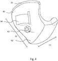
- Fig. 4 shows an exemplary in-the-ear hearing aid 60 according to one embodiment of the present invention.
- the shell 61 of the hearing aid 60 is customized to the ear of the user.
- the hearing aid 60 comprises a front plate 62.
- the front plate 62 has a button 63 for turning the volume up and down and a battery door 64 that can be opened for removing and/or inserting a battery.
- the deep end of the hearing aid goes a little bit into the ear canal.
- the depth of the hearing aid 60 is measured from the front plate to the deepest end, such as along length L1.
- the width is measured as the width of the front plate, such as along length L2.
- the width is often greater than the depth. Thereby, the ITE-axis may not correspond to the longitudinal axis of the hearing aid.
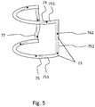
- Fig. 5 shows schematically a direction of the currents flowing in an exemplary antenna 73 of a hearing aid according to the present invention.
- the antenna 73 comprises a first antenna branch 74, a second antenna branch 75 and a third antenna branch 77.
- the first antenna branch 74 comprises a first, rectilinear section 741 and a second, curved section 742.
- the second antenna branch 75 also comprises a first, rectilinear section 751 and a second, curved section 752.
- the second antenna branch 75 is a mirror of the first antenna branch 74.
- the current distribution in the third antenna branch 77 reaches a maximum. In consequence, the dipole moment radiated by the third antenna branch 77 is maximized.
- the third antenna branch 77 is normally oriented substantially perpendicular to the face plate (not shown in Fig. 5 ) and to the lateral surface of the head of the user, when the hearing aid is worn in its operational position.
- the maximized current flowing in the third antenna branch 77 contributes to a strong electromagnetic field that travels around the head of the user, passing also by the top of the head. In other words, wireless communication between the two hearing aids worn in the ear is enabled.
- a robust and powerful antenna solution for the hearing aid is hereby provided that in addition experiences low losses.
- only one of the first and the second antenna branches surrounds the battery, when the battery is positioned according to the use.
- the two branches then cannot be short-circuited, as they are not in proximity to the same piece of metal, here battery.
- the capacitive coupling between parallel plates, i.e. the battery surface and the antenna trace becomes an increasingly advantageous connection for the high frequency signals, to the point where they might as well have been connected directly. Therefore, it is preferred to avoid designing all antenna traces at a close distance to the same conductive object.
- the antenna and/or the wireless communication unit are comprised in a substrate.
- the substrate allows bending the antenna to fit inside the hearing aid.
- a first segment of the first branch of the antenna may be placed on a first side of the substrate while another segment of the first branch of the antenna may be placed on a second side of the substrate.
- a second segment of the second branch of the antenna may be placed on a first side of a substrate while another segment of the second branch of the antenna may be placed on a second side of the same substrate.
- first, second, and the like does not imply any particular order, but they are included to identify individual elements. Moreover, the use of the terms first, second, etc. does not denote any order or importance, but rather the terms first, second, etc. are used to distinguish one element from another. Note that the words first and second are used here and elsewhere for labelling purposes only and are not intended to denote any specific spatial or temporal ordering. Furthermore, the labelling of a first element does not imply the presence of a second element.
Landscapes
- Engineering & Computer Science (AREA)
- Computer Networks & Wireless Communication (AREA)
- Health & Medical Sciences (AREA)
- General Health & Medical Sciences (AREA)
- Neurosurgery (AREA)
- Otolaryngology (AREA)
- Physics & Mathematics (AREA)
- Acoustics & Sound (AREA)
- Signal Processing (AREA)
- Support Of Aerials (AREA)
- Headphones And Earphones (AREA)
- Transceivers (AREA)
- Details Of Aerials (AREA)
Priority Applications (4)
| Application Number | Priority Date | Filing Date | Title |
|---|---|---|---|
| EP17188504.9A EP3451701A1 (de) | 2017-08-30 | 2017-08-30 | Hörgerät mit antenne |
| US16/101,297 US10834511B2 (en) | 2017-08-30 | 2018-08-10 | Hearing aid with an antenna |
| JP2018153298A JP2019050557A (ja) | 2017-08-30 | 2018-08-16 | アンテナを備える補聴器 |
| CN201810985513.0A CN109429163A (zh) | 2017-08-30 | 2018-08-28 | 具有天线的助听器 |
Applications Claiming Priority (1)
| Application Number | Priority Date | Filing Date | Title |
|---|---|---|---|
| EP17188504.9A EP3451701A1 (de) | 2017-08-30 | 2017-08-30 | Hörgerät mit antenne |
Publications (1)
| Publication Number | Publication Date |
|---|---|
| EP3451701A1 true EP3451701A1 (de) | 2019-03-06 |
Family
ID=59829162
Family Applications (1)
| Application Number | Title | Priority Date | Filing Date |
|---|---|---|---|
| EP17188504.9A Withdrawn EP3451701A1 (de) | 2017-08-30 | 2017-08-30 | Hörgerät mit antenne |
Country Status (4)
| Country | Link |
|---|---|
| US (1) | US10834511B2 (de) |
| EP (1) | EP3451701A1 (de) |
| JP (1) | JP2019050557A (de) |
| CN (1) | CN109429163A (de) |
Families Citing this family (8)
| Publication number | Priority date | Publication date | Assignee | Title |
|---|---|---|---|---|
| DK3471200T3 (da) * | 2017-10-16 | 2020-04-27 | Widex As | Antenne til en høreunderstøttelsesindretning |
| EP3499913B1 (de) | 2017-12-14 | 2020-12-02 | GN Hearing A/S | Mehrarmige dipolantenne für hörinstrumente |
| US10547957B1 (en) | 2018-09-27 | 2020-01-28 | Starkey Laboratories, Inc. | Hearing aid antenna for high-frequency data communication |
| EP3780267A1 (de) | 2019-08-16 | 2021-02-17 | Sonova AG | Hörgerät und verfahren zur herstellung davon |
| DE102019219484B4 (de) * | 2019-12-12 | 2021-08-26 | Sivantos Pte. Ltd. | Leiterplatte eines Hörgeräts |
| DE102020201479A1 (de) * | 2020-02-06 | 2021-08-12 | Sivantos Pte. Ltd. | Hörgerät |
| DE102020201480A1 (de) * | 2020-02-06 | 2021-08-12 | Sivantos Pte. Ltd. | Hörgerät |
| CN113410615B (zh) * | 2021-05-26 | 2023-01-20 | 潍坊歌尔电子有限公司 | 线控蓝牙耳机天线和蓝牙耳机 |
Citations (4)
| Publication number | Priority date | Publication date | Assignee | Title |
|---|---|---|---|---|
| US20140010392A1 (en) * | 2012-07-06 | 2014-01-09 | Gn Resound A/S | Bte hearing aid having two driven antennas |
| US20150036854A1 (en) * | 2013-05-01 | 2015-02-05 | Starkey Laboratories, Inc. | Hearing assistance device with balanced feed-line for antenna |
| EP2871861A1 (de) * | 2013-11-11 | 2015-05-13 | GN Resound A/S | Hörgerät mit Antenne |
| EP2986030A1 (de) * | 2014-08-15 | 2016-02-17 | GN Resound A/S | Hörgerät mit Antenne |
Family Cites Families (10)
| Publication number | Priority date | Publication date | Assignee | Title |
|---|---|---|---|---|
| US20130343586A1 (en) * | 2012-06-25 | 2013-12-26 | Gn Resound A/S | Hearing aid having a slot antenna |
| US8878735B2 (en) * | 2012-06-25 | 2014-11-04 | Gn Resound A/S | Antenna system for a wearable computing device |
| CN103457454B (zh) * | 2013-08-21 | 2016-08-24 | 华为技术有限公司 | 一种电压变换器和共模噪声阻抗调整方法 |
| US9237405B2 (en) * | 2013-11-11 | 2016-01-12 | Gn Resound A/S | Hearing aid with an antenna |
| EP2871862B1 (de) * | 2013-11-11 | 2022-05-04 | GN Hearing A/S | Hörgerät mit Antenne |
| US10187734B2 (en) * | 2014-08-15 | 2019-01-22 | Gn Hearing A/S | Hearing aid with an antenna |
| US10595138B2 (en) * | 2014-08-15 | 2020-03-17 | Gn Hearing A/S | Hearing aid with an antenna |
| EP3101916B1 (de) * | 2015-06-03 | 2019-05-01 | GN Hearing A/S | Hörgeräteschale mit führungsstruktur |
| DK3103511T3 (da) * | 2015-06-11 | 2019-06-03 | Oticon As | Cochlear høreanordning med kabelantenne |
| US10277996B2 (en) * | 2015-12-01 | 2019-04-30 | Gn Hearing A/S | Hearing aid with a flexible carrier antenna and related method |
-
2017
- 2017-08-30 EP EP17188504.9A patent/EP3451701A1/de not_active Withdrawn
-
2018
- 2018-08-10 US US16/101,297 patent/US10834511B2/en active Active
- 2018-08-16 JP JP2018153298A patent/JP2019050557A/ja active Pending
- 2018-08-28 CN CN201810985513.0A patent/CN109429163A/zh active Pending
Patent Citations (4)
| Publication number | Priority date | Publication date | Assignee | Title |
|---|---|---|---|---|
| US20140010392A1 (en) * | 2012-07-06 | 2014-01-09 | Gn Resound A/S | Bte hearing aid having two driven antennas |
| US20150036854A1 (en) * | 2013-05-01 | 2015-02-05 | Starkey Laboratories, Inc. | Hearing assistance device with balanced feed-line for antenna |
| EP2871861A1 (de) * | 2013-11-11 | 2015-05-13 | GN Resound A/S | Hörgerät mit Antenne |
| EP2986030A1 (de) * | 2014-08-15 | 2016-02-17 | GN Resound A/S | Hörgerät mit Antenne |
Also Published As
| Publication number | Publication date |
|---|---|
| CN109429163A (zh) | 2019-03-05 |
| US20190069101A1 (en) | 2019-02-28 |
| JP2019050557A (ja) | 2019-03-28 |
| US10834511B2 (en) | 2020-11-10 |
Similar Documents
| Publication | Publication Date | Title |
|---|---|---|
| US10834511B2 (en) | Hearing aid with an antenna | |
| US10187734B2 (en) | Hearing aid with an antenna | |
| US9237405B2 (en) | Hearing aid with an antenna | |
| US11172315B2 (en) | Hearing aid having combined antennas | |
| US9369813B2 (en) | BTE hearing aid having two driven antennas | |
| EP2723101B1 (de) | BTE-Hörgerät mit ausgeglichener Antenne | |
| US9554219B2 (en) | BTE hearing aid having a balanced antenna | |
| JP6514152B2 (ja) | 複合アンテナを有する耳内補聴器 | |
| US9402141B2 (en) | BTE hearing aid with an antenna partition plane | |
| EP2986030B1 (de) | Hörgerät mit Antenne | |
| JP2016178676A (ja) | アンテナを備える補聴器 | |
| EP2871861B1 (de) | Hörgerät mit Antenne | |
| DK201470487A1 (en) | A hearing aid with an antenna | |
| EP3110170B1 (de) | Hörgerät mit kombinierten antennen | |
| DK201370665A1 (en) | A hearing aid with an antenna |
Legal Events
| Date | Code | Title | Description |
|---|---|---|---|
| PUAI | Public reference made under article 153(3) epc to a published international application that has entered the european phase |
Free format text: ORIGINAL CODE: 0009012 |
|
| STAA | Information on the status of an ep patent application or granted ep patent |
Free format text: STATUS: THE APPLICATION HAS BEEN PUBLISHED |
|
| AK | Designated contracting states |
Kind code of ref document: A1 Designated state(s): AL AT BE BG CH CY CZ DE DK EE ES FI FR GB GR HR HU IE IS IT LI LT LU LV MC MK MT NL NO PL PT RO RS SE SI SK SM TR |
|
| AX | Request for extension of the european patent |
Extension state: BA ME |
|
| STAA | Information on the status of an ep patent application or granted ep patent |
Free format text: STATUS: REQUEST FOR EXAMINATION WAS MADE |
|
| 17P | Request for examination filed |
Effective date: 20190906 |
|
| RBV | Designated contracting states (corrected) |
Designated state(s): AL AT BE BG CH CY CZ DE DK EE ES FI FR GB GR HR HU IE IS IT LI LT LU LV MC MK MT NL NO PL PT RO RS SE SI SK SM TR |
|
| STAA | Information on the status of an ep patent application or granted ep patent |
Free format text: STATUS: EXAMINATION IS IN PROGRESS |
|
| STAA | Information on the status of an ep patent application or granted ep patent |
Free format text: STATUS: EXAMINATION IS IN PROGRESS |
|
| 17Q | First examination report despatched |
Effective date: 20210719 |
|
| STAA | Information on the status of an ep patent application or granted ep patent |
Free format text: STATUS: THE APPLICATION IS DEEMED TO BE WITHDRAWN |
|
| 18D | Application deemed to be withdrawn |
Effective date: 20211130 |