EP3451421A1 - Electrode for secondary battery, and lithium secondary battery comprising same - Google Patents
Electrode for secondary battery, and lithium secondary battery comprising same Download PDFInfo
- Publication number
- EP3451421A1 EP3451421A1 EP17813592.7A EP17813592A EP3451421A1 EP 3451421 A1 EP3451421 A1 EP 3451421A1 EP 17813592 A EP17813592 A EP 17813592A EP 3451421 A1 EP3451421 A1 EP 3451421A1
- Authority
- EP
- European Patent Office
- Prior art keywords
- active material
- electrode active
- electrode
- material layer
- secondary battery
- Prior art date
- Legal status (The legal status is an assumption and is not a legal conclusion. Google has not performed a legal analysis and makes no representation as to the accuracy of the status listed.)
- Granted
Links
Images


Classifications
-
- H—ELECTRICITY
- H01—ELECTRIC ELEMENTS
- H01M—PROCESSES OR MEANS, e.g. BATTERIES, FOR THE DIRECT CONVERSION OF CHEMICAL ENERGY INTO ELECTRICAL ENERGY
- H01M10/00—Secondary cells; Manufacture thereof
- H01M10/05—Accumulators with non-aqueous electrolyte
- H01M10/052—Li-accumulators
-
- H—ELECTRICITY
- H01—ELECTRIC ELEMENTS
- H01M—PROCESSES OR MEANS, e.g. BATTERIES, FOR THE DIRECT CONVERSION OF CHEMICAL ENERGY INTO ELECTRICAL ENERGY
- H01M4/00—Electrodes
- H01M4/02—Electrodes composed of, or comprising, active material
- H01M4/13—Electrodes for accumulators with non-aqueous electrolyte, e.g. for lithium-accumulators; Processes of manufacture thereof
- H01M4/131—Electrodes based on mixed oxides or hydroxides, or on mixtures of oxides or hydroxides, e.g. LiCoOx
-
- H—ELECTRICITY
- H01—ELECTRIC ELEMENTS
- H01M—PROCESSES OR MEANS, e.g. BATTERIES, FOR THE DIRECT CONVERSION OF CHEMICAL ENERGY INTO ELECTRICAL ENERGY
- H01M10/00—Secondary cells; Manufacture thereof
- H01M10/42—Methods or arrangements for servicing or maintenance of secondary cells or secondary half-cells
- H01M10/48—Accumulators combined with arrangements for measuring, testing or indicating the condition of cells, e.g. the level or density of the electrolyte
-
- H—ELECTRICITY
- H01—ELECTRIC ELEMENTS
- H01M—PROCESSES OR MEANS, e.g. BATTERIES, FOR THE DIRECT CONVERSION OF CHEMICAL ENERGY INTO ELECTRICAL ENERGY
- H01M4/00—Electrodes
- H01M4/02—Electrodes composed of, or comprising, active material
- H01M4/04—Processes of manufacture in general
- H01M4/0402—Methods of deposition of the material
- H01M4/0404—Methods of deposition of the material by coating on electrode collectors
-
- H—ELECTRICITY
- H01—ELECTRIC ELEMENTS
- H01M—PROCESSES OR MEANS, e.g. BATTERIES, FOR THE DIRECT CONVERSION OF CHEMICAL ENERGY INTO ELECTRICAL ENERGY
- H01M4/00—Electrodes
- H01M4/02—Electrodes composed of, or comprising, active material
- H01M4/13—Electrodes for accumulators with non-aqueous electrolyte, e.g. for lithium-accumulators; Processes of manufacture thereof
- H01M4/139—Processes of manufacture
- H01M4/1391—Processes of manufacture of electrodes based on mixed oxides or hydroxides, or on mixtures of oxides or hydroxides, e.g. LiCoOx
-
- H—ELECTRICITY
- H01—ELECTRIC ELEMENTS
- H01M—PROCESSES OR MEANS, e.g. BATTERIES, FOR THE DIRECT CONVERSION OF CHEMICAL ENERGY INTO ELECTRICAL ENERGY
- H01M4/00—Electrodes
- H01M4/02—Electrodes composed of, or comprising, active material
- H01M4/36—Selection of substances as active materials, active masses, active liquids
- H01M4/48—Selection of substances as active materials, active masses, active liquids of inorganic oxides or hydroxides
- H01M4/50—Selection of substances as active materials, active masses, active liquids of inorganic oxides or hydroxides of manganese
- H01M4/505—Selection of substances as active materials, active masses, active liquids of inorganic oxides or hydroxides of manganese of mixed oxides or hydroxides containing manganese for inserting or intercalating light metals, e.g. LiMn2O4 or LiMn2OxFy
-
- H—ELECTRICITY
- H01—ELECTRIC ELEMENTS
- H01M—PROCESSES OR MEANS, e.g. BATTERIES, FOR THE DIRECT CONVERSION OF CHEMICAL ENERGY INTO ELECTRICAL ENERGY
- H01M4/00—Electrodes
- H01M4/02—Electrodes composed of, or comprising, active material
- H01M4/36—Selection of substances as active materials, active masses, active liquids
- H01M4/48—Selection of substances as active materials, active masses, active liquids of inorganic oxides or hydroxides
- H01M4/52—Selection of substances as active materials, active masses, active liquids of inorganic oxides or hydroxides of nickel, cobalt or iron
- H01M4/525—Selection of substances as active materials, active masses, active liquids of inorganic oxides or hydroxides of nickel, cobalt or iron of mixed oxides or hydroxides containing iron, cobalt or nickel for inserting or intercalating light metals, e.g. LiNiO2, LiCoO2 or LiCoOxFy
-
- H—ELECTRICITY
- H01—ELECTRIC ELEMENTS
- H01M—PROCESSES OR MEANS, e.g. BATTERIES, FOR THE DIRECT CONVERSION OF CHEMICAL ENERGY INTO ELECTRICAL ENERGY
- H01M4/00—Electrodes
- H01M4/02—Electrodes composed of, or comprising, active material
- H01M4/36—Selection of substances as active materials, active masses, active liquids
- H01M4/58—Selection of substances as active materials, active masses, active liquids of inorganic compounds other than oxides or hydroxides, e.g. sulfides, selenides, tellurides, halogenides or LiCoFy; of polyanionic structures, e.g. phosphates, silicates or borates
- H01M4/583—Carbonaceous material, e.g. graphite-intercalation compounds or CFx
-
- H—ELECTRICITY
- H01—ELECTRIC ELEMENTS
- H01M—PROCESSES OR MEANS, e.g. BATTERIES, FOR THE DIRECT CONVERSION OF CHEMICAL ENERGY INTO ELECTRICAL ENERGY
- H01M4/00—Electrodes
- H01M4/02—Electrodes composed of, or comprising, active material
- H01M4/62—Selection of inactive substances as ingredients for active masses, e.g. binders, fillers
- H01M4/621—Binders
- H01M4/622—Binders being polymers
- H01M4/623—Binders being polymers fluorinated polymers
-
- H—ELECTRICITY
- H01—ELECTRIC ELEMENTS
- H01M—PROCESSES OR MEANS, e.g. BATTERIES, FOR THE DIRECT CONVERSION OF CHEMICAL ENERGY INTO ELECTRICAL ENERGY
- H01M10/00—Secondary cells; Manufacture thereof
- H01M10/05—Accumulators with non-aqueous electrolyte
- H01M10/052—Li-accumulators
- H01M10/0525—Rocking-chair batteries, i.e. batteries with lithium insertion or intercalation in both electrodes; Lithium-ion batteries
-
- H—ELECTRICITY
- H01—ELECTRIC ELEMENTS
- H01M—PROCESSES OR MEANS, e.g. BATTERIES, FOR THE DIRECT CONVERSION OF CHEMICAL ENERGY INTO ELECTRICAL ENERGY
- H01M4/00—Electrodes
- H01M4/02—Electrodes composed of, or comprising, active material
- H01M2004/021—Physical characteristics, e.g. porosity, surface area
-
- H—ELECTRICITY
- H01—ELECTRIC ELEMENTS
- H01M—PROCESSES OR MEANS, e.g. BATTERIES, FOR THE DIRECT CONVERSION OF CHEMICAL ENERGY INTO ELECTRICAL ENERGY
- H01M4/00—Electrodes
- H01M4/02—Electrodes composed of, or comprising, active material
- H01M2004/026—Electrodes composed of, or comprising, active material characterised by the polarity
- H01M2004/027—Negative electrodes
-
- H—ELECTRICITY
- H01—ELECTRIC ELEMENTS
- H01M—PROCESSES OR MEANS, e.g. BATTERIES, FOR THE DIRECT CONVERSION OF CHEMICAL ENERGY INTO ELECTRICAL ENERGY
- H01M4/00—Electrodes
- H01M4/02—Electrodes composed of, or comprising, active material
- H01M2004/026—Electrodes composed of, or comprising, active material characterised by the polarity
- H01M2004/028—Positive electrodes
-
- H—ELECTRICITY
- H01—ELECTRIC ELEMENTS
- H01M—PROCESSES OR MEANS, e.g. BATTERIES, FOR THE DIRECT CONVERSION OF CHEMICAL ENERGY INTO ELECTRICAL ENERGY
- H01M4/00—Electrodes
- H01M4/02—Electrodes composed of, or comprising, active material
- H01M4/64—Carriers or collectors
- H01M4/66—Selection of materials
- H01M4/661—Metal or alloys, e.g. alloy coatings
-
- Y—GENERAL TAGGING OF NEW TECHNOLOGICAL DEVELOPMENTS; GENERAL TAGGING OF CROSS-SECTIONAL TECHNOLOGIES SPANNING OVER SEVERAL SECTIONS OF THE IPC; TECHNICAL SUBJECTS COVERED BY FORMER USPC CROSS-REFERENCE ART COLLECTIONS [XRACs] AND DIGESTS
- Y02—TECHNOLOGIES OR APPLICATIONS FOR MITIGATION OR ADAPTATION AGAINST CLIMATE CHANGE
- Y02E—REDUCTION OF GREENHOUSE GAS [GHG] EMISSIONS, RELATED TO ENERGY GENERATION, TRANSMISSION OR DISTRIBUTION
- Y02E60/00—Enabling technologies; Technologies with a potential or indirect contribution to GHG emissions mitigation
- Y02E60/10—Energy storage using batteries
Definitions
- the present invention relates to an electrode for a secondary battery and a lithium secondary battery including the same, and particularly, to an electrode for a secondary battery which has high capacity and also ensures stability, and a lithium secondary battery including the same.
- a secondary battery having a higher capacity per unit area is preferable.
- a secondary battery needs to also ensure high stability to prevent damage or fire caused by an external impact or a rapid change in internal temperature or pressure.
- a nail penetration test As one item for evaluating the stability of a secondary battery, there is a nail penetration test. In the nail penetration test, whether or not heat-generation, ignition, explosion and the like of a secondary battery occur when a sharp material such as a nail or the like damages a secondary battery is tested. In order to pass the nail penetration test, when a sharp material damages a secondary battery through collisions therebetween, an electrode should be broken and thus short-circuited. This is because ignition or explosion does not occur when the electrode is broken.
- a nickel-cobalt-manganese-based lithium oxide is frequently used as an electrode active material of a lithium secondary battery.
- a high-concentration nickel-cobalt-manganese-based lithium oxide including a large amount of nickel among transition metals realizes high energy density per unit volume, and thus is frequently used in medium- to large-sized batteries requiring high capacity.
- an electrode using a high-concentration nickel-cobalt-manganese-based lithium oxide as an electrode active material is not easily broken by an external impact due to its high elongation, which causes explosion or ignition of the electrode.
- elongation refers to a ratio at which a material is stretched in a tension test.
- the present invention is designed to solve the problems of the prior art, and it is an aspect of the present invention to provide an electrode for a secondary battery which has high capacity and is also able to get an excellent evaluation in a nail penetration test, and a lithium secondary battery including the same.
- an electrode for a secondary battery which includes an electrode current collector; a first electrode active material layer formed on the electrode current collector; and a second electrode active material layer formed on the first electrode active material layer, wherein a layer composed of the electrode current collector and the first electrode active material layer has a tensile strain of 1.2% or less.
- the second electrode active material layer may have a higher energy density per unit volume than that of the first electrode active material layer.
- each of the first electrode active material layer and the second electrode active material layer may include a lithium-transition metal oxide as an active material, and particularly, the lithium-transition metal oxide may be represented by Chemical Formula 1 below.
- Chemical Formula 1 Li 1+x [Ni a CO b Mn c ] 1-x O 2
- the lithium-transition metal oxides included in the first electrode active material layer and the second electrode active material layer may have the same or different compositions.
- the first electrode active material layer and the second electrode active material layer may have an energy density per unit area of 1 to 6 mAh/cm 2 .
- the first electrode active material layer may have a thickness of 15 to 150 ⁇ m, and the second electrode active material layer may have a thickness of 15 to 100 ⁇ m.
- the electrode according to the present invention may further include, as necessary, a lithium ion-conductive layer laminated on the second electrode active material layer and containing a lithium ion-conductive gel swollen with a non-aqueous electrolyte; and a heat-resistant porous layer laminated on a surface of the lithium ion-conductive layer and containing insulating metal oxide particles.
- the electrode is a positive electrode.
- a lithium secondary battery including the electrode according to the present invention.
- An electrode according to the present invention includes two electrode active material layers, and thus can include a relatively large amount of active material compared to a conventional electrode including one electrode active material layer, and can prevent peeling from a current collector and migration of a binder so that high capacity can be stably realized.
- an active material layer having low elongation is formed as a first electrode active material layer provided closer to a current collector so that a fracture property of the electrode increases when an external impact is applied, and thus excellent stability can be realized.
- FIG. 1 is a diagram of an electrode for a secondary battery according to an embodiment of the present invention.
- an electrode for a secondary battery E includes an electrode current collector 10, a first electrode active material layer 20 formed on the electrode current collector 10, and a second electrode active material layer 30 formed on the first electrode active material layer.
- an electrode active material layer is laminated on only one surface of the electrode current collector 10, but the present invention is not limited thereto.
- an electrode active material layer may be laminated on both surfaces of the electrode current collector 10.
- the electrode current collector 10 may be an electrode current collector generally used in the art, and types thereof are not particularly limited as long as it does not cause a chemical change in the battery and has conductivity.
- the electrode current collector 10 is copper, stainless steel, aluminum, nickel, titanium, calcined carbon, or copper or stainless steel whose surface is treated with carbon, nickel, titanium, silver or the like, an aluminum-cadmium alloy or the like.
- the electrode current collector may have fine irregularities at a surface thereof to increase adhesion to an active material layer, may be used in any of various forms such as a film, a sheet, a foil, a net, a porous material, a foam, a non-woven fabric and the like, and may have a thickness of 3 to 500 ⁇ m.
- a layer composed of the electrode current collector and the first electrode active material layer 20 has an elongation of 1.2% or less, preferably, 1.0% or less.
- elongation refers to a ratio at which a material is stretched in a tension test, and a material having high elongation is more likely to be stretched without being broken by an external impact. That is, elongation is used as a measure of the fracture performance of a material. Therefore, a material having low elongation tends to be broken by an external impact, and a material having high elongation tends to be stretched without being broken by an external impact.
- elongation is affected by the material and thickness of a current collector, the thickness of a first electrode active material layer, a composition of a slurry constituting a first electrode active material layer, the type of active material used, a particle diameter of an active material, and the like. Therefore, when the above-described factors are appropriately adjusted, a layer composed of the electrode current collector and the first electrode active material layer may have an elongation within a desired range.
- the elongation of a layer composed of the electrode current collector and the first electrode active material layer may be measured by the following method.
- a slurry for forming a first electrode active material layer is applied on an electrode current collector and dried to prepare a sample with a size of 15 mm (W) X 150 mm (L).
- the sample is mounted in a sample-gripping part of an elongation measurement device (e.g., Instron 3345 UTM) as shown in FIG. 6 , and then pulled at a rate of 5 mm/min to measure tensile strain. In this case, tensile strain immediately before the sample is broken is determined as elongation.
- an elongation measurement device e.g., Instron 3345 UTM
- the current collector and the first electrode active material layer are easily broken and short-circuited when an external impact caused by a sharp material is applied, and thus ignition or explosion of the battery may be effectively prevented.
- FIG. 2 is a diagram illustrating that an electrode for a secondary battery according to an embodiment of the present invention is subjected to a nail penetration test
- FIG. 3 is a diagram of an electrode after an electrode for a secondary battery according to an embodiment of the present invention has been subjected to a nail penetration test.
- a secondary battery needs to ensure high stability to prevent damage or fire caused by an external impact or a rapid change in internal temperature or pressure.
- a nail penetration test As one of the measures for evaluating the stability of a secondary battery, there is a nail penetration test. In the nail penetration test, whether or not heat-generation, ignition, explosion and the like of a secondary battery occur when a sharp material such as a nail or the like damages a secondary battery is tested. In order to pass the nail penetration test, when a sharp material damages a secondary battery by penetrating the secondary battery, an electrode should be broken. This is because ignition or explosion does not occur when the electrode is broken.
- an electrode active material layer or an electrode current collector needs to be easily broken. Therefore, in order to pass the nail penetration test, an electrode active material layer having lower elongation is preferable. This is because an electrode is easily broken as elongation is lower.
- the first electrode active material layer 20 having low elongation is laminated adjacent onto the electrode current collector 10 so that a layer composed of the electrode current collector 10 and the first electrode active material layer 20 has an elongation of 1.2% or less, and thus an electrode can be easily broken in a nail penetration test or real life as shown in FIG. 3 . That is, when a nail 100 penetrates the electrode E according to an embodiment of the present invention in a nail penetration test or real life, all of the electrode active material layers and the electrode current collector are broken as shown in FIG. 3 , and thus a risk of heat-generation, fire, or explosion of a secondary battery may be prevented.
- the second electrode active material layer 30 formed on the first electrode active material layer 20 does not affect the fracturing of the electrode, and thus a material having high elongation compared to the first electrode active material layer 20 may be used. Therefore, when the electrode according to the present invention includes two electrode active material layers, a selection range for a material that may be used as the second electrode active material layer 30 is widened, and thus a degree of freedom of design of the electrode may be improved.
- the second electrode active material layer 30 may have a higher energy density per unit area than that of the first electrode active material layer 20.
- a secondary battery having more excellent capacity with respect to the same volume compared to the case of an electrode including one electrode active material layer may be manufactured. That is, in the present invention, an electrode having both high capacity and excellent stability may be manufactured by forming an electrode active material layer with a two-layer structure, adjusting the elongation of a layer composed of an electrode current collector and a first electrode active material layer formed on the electrode current collector, which affects fracturing of the electrode, to a specific range, and forming an active material layer having excellent capacity as a second electrode active material layer.
- the first electrode active material layer may have an energy density per unit area of 1 to 6 mAh/cm 2 , preferably 1 to 5 mAh/cm 2 , and more preferably 1 to 4 mAh/cm 2 .
- the second electrode active material layer may have an energy density per unit area of 1 to 6 mAh/cm 2 , preferably 2 to 6 mAh/cm 2 , and more preferably, 3 to 6 mAh/cm 2 .
- the electrode according to the present invention may be appropriately used in medium- to large-sized high-capacity battery cells, and a thickness of the electrode may be reduced due to a decrease in a loading amount per electrode weight.
- each of the first electrode active material layer and the second electrode active material layer preferably includes a lithium-transition metal oxide as an active material.
- the lithium-transition metal oxide may be a nickel-cobalt-manganese-based lithium metal oxide represented by Chemical Formula 1 below. [Chemical Formula 1] Li 1+x [Ni a CO b Mn c ] 1-x O 2
- the nickel-cobalt-manganese-based lithium metal oxide represented by Chemical Formula 1 as an active material is a nickel-cobalt-manganese-based electrode active material including nickel among transition metals at 50 mol% or more.
- the lithium-transition metal oxide may be Li[Ni 0.6 CO 0.2 Mn 0.2 ]O 2 , Li[Ni 0.8 CO 0.1 Mn 0.1 ]O 2 , or the like, but the present invention is not limited thereto.
- the lithium-transition metal oxides included in the first electrode active material layer and the second electrode active material layer may have the same or different compositions.
- all of the active materials included in the first electrode active material layer and the second electrode active material layer may be nickel-cobalt-manganese-based lithium metal oxides.
- contents of nickel, cobalt, and manganese included in the lithium-transition metal oxide may be the same or different from each other.
- operating voltage is in an equal range, and thus a loss caused by a difference in operating voltage, which may occur when heterogeneous active materials are used, may be minimized.
- active materials included in the first electrode active material layer and the second electrode active material layer are only required to have homogeneous components, and contents of each component do not need to be the same.
- first electrode active material layer and the second electrode active material layer may further include, as necessary, a binder, a conductive material, a dispersant, or the like.
- any of various types of binder polymers such as a polyvinylidene fluoride-hexafluoropropylene copolymer (PVDF-co-HFP), polyvinylidene fluoride (PVDF), polyacrylonitrile, polymethyl methacrylate, polyvinyl alcohol, carboxymethyl cellulose (CMC), starches, hydroxypropyl cellulose, regenerated cellulose, polyvinyl pyrrolidone, tetrafluoroethylene, polyethylene, polypropylene, polyacrylic acid, an ethylene-propylene-diene monomer (EPDM), sulfonated EPDM, styrene-butadiene rubber (SBR), fluororubber, polyacrylic acid, a polymer in which hydrogen atoms of the above polymers are substituted with Li, Na, Ca or the like, various copolymers, and the like may be used.
- PVDF-co-HFP polyvinylidene fluoride-hexaflu
- the conductive material is not particularly limited as long as it does not cause a chemical change in the battery and has conductivity.
- the conductive material is graphite such as natural graphite, artificial graphite or the like; carbon black such as acetylene black, Ketjen black, channel black, furnace black, lamp black, thermal black or the like; a conductive fiber such as carbon fiber, metallic fiber or the like; a conductive tube such as carbon nanotubes or the like; metallic powder such as carbon fluoride powder, aluminum powder, nickel powder or the like; a conductive whisker such as zinc oxide, potassium titanate or the like; a conductive metal oxide such as titanium oxide or the like; or a conductive material such as a polyphenylene derivative or the like.
- the dispersant may be an aqueous dispersant or an organic dispersant such as N-methyl-2-pyrrolidone or the like.
- the first electrode active material layer may have a thickness of 15 to 150 ⁇ m
- the second electrode active material layer may have a thickness of 15 to 100 ⁇ m.
- the electrode according to the present invention may further include, as necessary, a lithium ion-conductive layer and a heat-resistant porous layer on the second electrode active material layer.
- FIG. 4 is a diagram of an electrode for a secondary battery according to another embodiment of the present invention.
- an electrode for a secondary battery E may include configurations further laminated on a plurality of electrode active material layers. That is, the electrode for a secondary battery E may include a lithium ion-conductive layer 40 laminated on a surface of the electrode active material layer and containing a lithium ion-conductive gel swollen with a non-aqueous electrolyte and a heat-resistant porous layer 50 laminated on a surface of the lithium ion-conductive layer 40 and containing insulating metal oxide particles.
- the heat-resistant porous layer 50 serves to prevent an increase in a temperature when an internal short-circuit occurs in a secondary battery to which the electrode according to an embodiment of the present invention is applied.
- the heat-resistant porous layer 50 when the heat-resistant porous layer 50 is laminated so as to directly come in contact with the electrode active material layer, several problems may occur. That is, when the heat-resistant porous layer 50 is laminated so as to directly come in contact with the electrode active material layer, insulating particles constituting the heat-resistant porous layer 50 may be introduced into pores in the electrode active material layer, and thus electrolyte permeability into the electrode active material layer may be degraded, which results in a degradation of ion conductivity of the electrode active material layer. Also, since conductivity between particles in the electrode active material layer may be degraded, load characteristics of a secondary battery in which an electrode is mounted may be degraded. In addition, since a pinhole is easily generated in the heat-resistant porous layer due to irregularities at a surface of the electrode active material layer formed by electrode active material particles, stability of a secondary battery may be degraded.
- a configuration for solving the problems is the lithium ion-conductive layer 40. That is, the lithium ion-conductive layer 40 is laminated on the electrode active material layer, and then the heat-resistant porous layer 50 is laminated thereon to prevent the generation of a pinhole in the heat-resistant porous layer 50 and also prevent the introduction of insulating particles into pores between electrode active material particles.
- the electrode according to the present invention may be used as an electrode for a lithium secondary battery, and particularly, may be usefully used as a positive electrode for a lithium secondary battery.
- the lithium secondary battery includes a positive electrode, a negative electrode disposed at a position facing the positive electrode, a separator interposed between the positive electrode and the negative electrode, and an electrolyte.
- the positive electrode may be the electrode according to the present invention.
- the secondary battery may optionally further include a battery container accommodating an electrode assembly composed of the positive electrode, the negative electrode and the separator, and a sealing member for sealing the battery container. Since description of the positive electrode is the same as described above, a detailed description thereof is omitted.
- the negative electrode includes a negative electrode current collector and a negative electrode active material layer disposed on at least one surface of the negative electrode current collector.
- the negative electrode current collector is not particularly limited as long as it does not cause a chemical change in the battery and has high conductivity.
- the negative electrode current collector is copper, stainless steel, aluminum, nickel, titanium, calcined carbon, or copper or stainless steel whose surface is treated with carbon, nickel, titanium, silver or the like, an aluminum-cadmium alloy or the like.
- the negative electrode current collector may commonly have a thickness of 3 to 500 ⁇ m, and, like the positive electrode current collector, may have fine irregularities at a surface thereof to increase adhesion of a negative electrode active material.
- the negative electrode current collector may be used in any of various forms such as a film, a sheet, a foil, a net, a porous material, a foam, a non-woven fabric and the like.
- the negative electrode active material layer includes a negative electrode active material, and, as necessary, optionally further includes at least one of a binder, a conductive material, and a dispersant.
- the negative electrode active material may be a compound capable of reversible intercalation and deintercalation of lithium ions.
- the negative electrode active material is any one or a mixture of two or more of a carbon material such as artificial graphite, natural graphite, graphitized carbon fiber, amorphous carbon or the like; a metal compound capable of alloying with lithium such as Si, Al, Sn, Pb, Zn, Bi, In, Mg, Ga, Cd, a Si alloy, a Sn alloy, an Al alloy or the like; a metal oxide capable of doping and dedoping lithium ions such as SiO v (0 ⁇ v ⁇ 2), SnO 2 , vanadium oxide or lithium vanadium oxide; and a composite including the metal compound and the carbon material such as a Si-C composite or a Sn-C composite.
- the negative electrode active material may be a lithium metal thin-film.
- low-crystallinity carbon, high-crystallinity carbon and the like all may be used as the carbon material.
- a representative example of the low-crystallinity carbon is soft carbon or hard carbon
- a representative example of the high-crystallinity carbon is high-temperature calcined carbon such as amorphous, platy, flake, spherical or fibrous natural graphite or artificial graphite, kish graphite, pyrolytic carbon, mesophase pitch-based carbon fiber, meso-carbon microbeads, mesophase pitches, petroleum or coal tar pitch-derived cokes or the like.
- the binder, the conductive material, and the dispersant may be the same as described above.
- the separator serves to separate the negative electrode and the positive electrode and to provide a flow passage for lithium ions.
- the separator is not particularly limited as long as it is used as a separator in a common lithium secondary battery, and particularly, a separator which exhibits low resistance to migration of electrolyte ions and has an excellent ability of absorbing an electrolyte solution is preferable.
- the separator may be, for example, a porous polymer film made of a polyolefin-based polymer such as an ethylene homopolymer, a propylene homopolymer, an ethylene/butene copolymer, an ethylene/hexene copolymer, an ethylene/methacrylate copolymer or the like, or a stacked structure having two or more layers made thereof.
- the separator may be a common porous non-woven fabric, for example, a non-woven fabric made of glass fiber with a high melting point, polyethylene terephthalate fiber or the like.
- the separator may be a coated separator including ceramic components or polymer materials, and optionally, may be used in a single-layer or multi-layer structure.
- the electrolyte used in the present invention may be an organic liquid electrolyte, an inorganic liquid electrolyte, a solid polymer electrolyte, a gel polymer electrolyte, an inorganic solid electrolyte, a molten-type inorganic electrolyte or the like, which may be used in the manufacture of a lithium secondary battery, but the present invention is not limited thereto.
- the electrolyte may include an organic solvent and a lithium salt.
- the organic solvent is not particularly limited as long as it may act as a medium capable of migrating ions involved in an electrochemical reaction of a battery.
- the organic solvent may be an ester-based solvent such as methyl acetate, ethyl acetate, ⁇ -butyrolactone, ⁇ -caprolactone or the like; an ether-based solvent such as dibutyl ether, tetrahydrofuran or the like; a ketone-based solvent such as cyclohexanone or the like; an aromatic hydrocarbon-based solvent such as benzene, fluorobenzene or the like; a carbonate-based solvent such as dimethyl carbonate (DMC), diethyl carbonate (DEC), methyl ethyl carbonate (MEC), ethyl methyl carbonate (EMC), ethylene carbonate (EC), propylene carbonate (PC) or the like; an alcohol-based solvent such as ethyl alcohol, isopropyl alcohol or the like;
- the carbonate-based solvent is preferable, and a mixture of a cyclic carbonate having high ionic conductivity and a high dielectric constant, which are capable of increasing the charging and discharging performance of a battery (e.g., EC, PC or the like) and a linear carbonate-based compound with low viscosity (e.g., EMC, DMC, DEC or the like) is more preferable.
- a battery e.g., EC, PC or the like
- a linear carbonate-based compound with low viscosity e.g., EMC, DMC, DEC or the like
- the lithium salt is not particularly limited as long as it can provide a lithium ion used in a lithium secondary battery.
- the lithium salt may be LiPF 6 , LiClO 4 , LiAsF 6 , LiBF 4 , LiSbF 6 , LiAlO 4 , LiAlCl 4 , LiCF 3 SO 3 , LiC 4 F 9 SO 3 , LiN(C 2 F 5 SO 3 ) 2 , LiN(C 2 F 5 SO 2 ) 2 , LiN(CF 3 SO 2 ) 2 .
- the concentration of the lithium salt preferably is within a range of 0.1 to 2.0 M. When the concentration of the lithium salt is within the above range, an electrolyte has appropriate conductivity and viscosity, and thus excellent performance of the electrolyte may be exhibited and lithium ions may be effectively migrated.
- the electrolyte may further include one or more additives such as a haloalkylene carbonate-based compound such as difluoroethylene carbonate or the like, pyridine, triethyl phosphite, triethanolamine, a cyclic ether, ethylene diamine, n-glyme, hexaphosphoric triamide, nitrobenzene derivatives, sulfur, quinoneimine dyes, N-substituted oxazolidinone, N,N-substituted imidazolidine, ethylene glycol dialkyl ethers, ammonium salts, pyrrole, 2-methoxyethanol, aluminum trichloride and the like.
- the additives may be included at 0.1 to 5 wt% with respect to the total weight of the electrolyte.
- the secondary battery according to the present invention may be usefully used in portable devices such as mobile phones, notebook PCs, digital cameras and the like and the electric vehicles such as a hybrid electric vehicle (HEV) and the like.
- portable devices such as mobile phones, notebook PCs, digital cameras and the like
- the electric vehicles such as a hybrid electric vehicle (HEV) and the like.
- HEV hybrid electric vehicle
- the positive electrode active material slurry A was applied on one surface of an aluminum current collector having a thickness of 70 ⁇ m, and then dried at 130 °C to form an electrode active material layer.
- the positive electrode active material slurry B was applied on one surface of an aluminum current collector having a thickness of 70 ⁇ m, and then dried at 130 °C to form an electrode active material layer.
- the positive electrode active material slurry C was applied on one surface of an aluminum current collector having a thickness of 65 ⁇ m, and then dried at 130 °C to form an electrode active material layer.
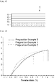
- Each current collector on which each of electrode active material layers according to Preparation Examples 1 to 3 was formed was cut to prepare a sample with a size of 15 mm (W) X 150 mm (L). Afterward, the sample was mounted in a sample-gripping part of an elongation measurement device (Instron 3345 UTM), and then pulled at a rate of 5 mm/min to measure tensile strain. The results thereof are shown in FIG. 5 .
- a layer composed of the current collector and the electrode active material layer prepared using the positive electrode active material slurry A had an elongation of 1.25%
- a layer composed of the current collector and the electrode active material layer prepared using the positive electrode active material slurry B had an elongation of 0.9%
- a layer composed of the current collector and the electrode active material layer prepared using the positive electrode active material slurry C had an elongation of 1.47%.
- the positive electrode active material slurry B according to Preparation Example 2 and the positive electrode active material slurry C according to Preparation Example 3 were applied on an aluminum current collector, dried at 130 °C, and then rolled to manufacture a positive electrode including a first electrode active material layer formed by the positive electrode active material slurry B and a second electrode active material layer formed by the positive electrode active material slurry C.
- the positive electrode active material slurry B according to Preparation Example 2 and the positive electrode active material slurry A according to Preparation Example 1 were applied on an aluminum current collector, dried at 130 °C, and then rolled to manufacture a positive electrode including a first electrode active material layer formed by the positive electrode active material slurry B and a second electrode active material layer formed by the positive electrode active material slurry A.
- the positive electrode active material slurry B according to Preparation Example 2 was applied in two layers on an aluminum current collector, dried at 130 °C, and then rolled to manufacture a positive electrode including a first electrode active material layer formed by the positive electrode active material slurry B and a second electrode active material layer formed by the positive electrode active material slurry B.
- the positive electrode active material slurry A according to Preparation Example 1 and the positive electrode active material slurry C according to Preparation Example 3 were applied on an aluminum current collector, dried at 130 °C, and then rolled to manufacture a positive electrode including a first electrode active material layer formed by the positive electrode active material slurry A and a second electrode active material layer formed by the positive electrode active material slurry C.
- the positive electrode active material slurry A according to Preparation Example 1 and the positive electrode active material slurry B according to Preparation Example 2 were applied on an aluminum current collector, dried at 130 °C, and then rolled to manufacture a positive electrode including a first electrode active material layer formed by the positive electrode active material slurry A and a second electrode active material layer formed by the positive electrode active material slurry B.
- the positive electrode active material slurry A according to Preparation Example 1 was applied in two layers on an aluminum current collector, dried at 130 °C, and then rolled to manufacture a positive electrode including a first electrode active material layer formed by the positive electrode active material slurry A and a second electrode active material layer formed by the positive electrode active material slurry A.
- the positive electrode active material slurry C according to Preparation Example 3 and the positive electrode active material slurry A according to Preparation Example 1 were applied on an aluminum current collector, dried at 130 °C, and then rolled to manufacture a positive electrode including a first electrode active material layer formed by the positive electrode active material slurry C and a second electrode active material layer formed by the positive electrode active material slurry A.
- the positive electrode active material slurry C according to Preparation Example 3 and the positive electrode active material slurry B according to Preparation Example 2 were applied on an aluminum current collector, dried at 130 °C, and then rolled to manufacture a positive electrode including a first electrode active material layer formed by the positive electrode active material slurry C and a second electrode active material layer formed by the positive electrode active material slurry B.
- the positive electrode active material slurry C according to Preparation Example 3 was applied in two layers on an aluminum current collector, dried at 130 °C, and then rolled to manufacture a positive electrode including a first electrode active material layer formed by the positive electrode active material slurry C and a second electrode active material layer formed by the positive electrode active material slurry C.
- a porous polyethylene separator was interposed between each positive electrode according to Examples 1 to 3 and Comparative Examples 1 to 6 and a negative electrode to manufacture an electrode assembly.
- the negative electrode was manufactured by mixing natural graphite as a negative electrode active material, carbon black as a conductive material, and PVDF as a binder in a weight ratio of 85:10:5 in NMP as a solvent to prepare a composition for forming a negative electrode active material layer and applying the composition on one surface of a copper current collector.
- the electrode assembly thus manufactured was disposed in a case, and then an electrolyte was injected into the inside of the case to manufacture a lithium secondary battery.
Landscapes
- Chemical & Material Sciences (AREA)
- Chemical Kinetics & Catalysis (AREA)
- Electrochemistry (AREA)
- General Chemical & Material Sciences (AREA)
- Engineering & Computer Science (AREA)
- Inorganic Chemistry (AREA)
- Manufacturing & Machinery (AREA)
- Materials Engineering (AREA)
- Battery Electrode And Active Subsutance (AREA)
- Secondary Cells (AREA)
Abstract
Description
- This application claims priority to and the benefit of Korean Patent Application No.
10-2016-0073967, filed on June 14, 2016 10-2017-0074716, filed on June 14, 2017 - The present invention relates to an electrode for a secondary battery and a lithium secondary battery including the same, and particularly, to an electrode for a secondary battery which has high capacity and also ensures stability, and a lithium secondary battery including the same.
- In order to use electronic devices in which a secondary battery capable of repetitive charging and discharging is installed for a long time, a secondary battery having a higher capacity per unit area is preferable. However, a secondary battery needs to also ensure high stability to prevent damage or fire caused by an external impact or a rapid change in internal temperature or pressure.
- As one item for evaluating the stability of a secondary battery, there is a nail penetration test. In the nail penetration test, whether or not heat-generation, ignition, explosion and the like of a secondary battery occur when a sharp material such as a nail or the like damages a secondary battery is tested. In order to pass the nail penetration test, when a sharp material damages a secondary battery through collisions therebetween, an electrode should be broken and thus short-circuited. This is because ignition or explosion does not occur when the electrode is broken.
- Meanwhile, in recent years, a nickel-cobalt-manganese-based lithium oxide is frequently used as an electrode active material of a lithium secondary battery. Among them, a high-concentration nickel-cobalt-manganese-based lithium oxide including a large amount of nickel among transition metals realizes high energy density per unit volume, and thus is frequently used in medium- to large-sized batteries requiring high capacity. However, an electrode using a high-concentration nickel-cobalt-manganese-based lithium oxide as an electrode active material is not easily broken by an external impact due to its high elongation, which causes explosion or ignition of the electrode. In this case, elongation refers to a ratio at which a material is stretched in a tension test.
- Therefore, the need for a secondary battery which has high capacity per unit area and simultaneously exhibits high safety is increasing.
- Korean Patent No.
10-0557714 - The present invention is designed to solve the problems of the prior art, and it is an aspect of the present invention to provide an electrode for a secondary battery which has high capacity and is also able to get an excellent evaluation in a nail penetration test, and a lithium secondary battery including the same.
- According to an embodiment of the present invention, there is provided an electrode for a secondary battery which includes an electrode current collector; a first electrode active material layer formed on the electrode current collector; and a second electrode active material layer formed on the first electrode active material layer, wherein a layer composed of the electrode current collector and the first electrode active material layer has a tensile strain of 1.2% or less.
- In this case, the second electrode active material layer may have a higher energy density per unit volume than that of the first electrode active material layer.
- In addition, each of the first electrode active material layer and the second electrode active material layer may include a lithium-transition metal oxide as an active material, and particularly, the lithium-transition metal oxide may be represented by Chemical Formula 1 below.
[Chemical Formula 1] Li1+x[NiaCObMnc]1-xO2
- In Chemical Formula 1, -0.2<x<0.2, 0.5≤a≤0.98, 0.01≤b≤0.4, and 0.01≤c≤0.4.
- Meanwhile, the lithium-transition metal oxides included in the first electrode active material layer and the second electrode active material layer may have the same or different compositions.
- The first electrode active material layer and the second electrode active material layer may have an energy density per unit area of 1 to 6 mAh/cm2.
- The first electrode active material layer may have a thickness of 15 to 150 µm, and the second electrode active material layer may have a thickness of 15 to 100 µm.
- In addition, the electrode according to the present invention may further include, as necessary, a lithium ion-conductive layer laminated on the second electrode active material layer and containing a lithium ion-conductive gel swollen with a non-aqueous electrolyte; and a heat-resistant porous layer laminated on a surface of the lithium ion-conductive layer and containing insulating metal oxide particles.
- Preferably, the electrode is a positive electrode.
- According to an embodiment of the present invention, there is provided a lithium secondary battery including the electrode according to the present invention.
- An electrode according to the present invention includes two electrode active material layers, and thus can include a relatively large amount of active material compared to a conventional electrode including one electrode active material layer, and can prevent peeling from a current collector and migration of a binder so that high capacity can be stably realized.
- In addition, in the electrode according to the present invention, an active material layer having low elongation is formed as a first electrode active material layer provided closer to a current collector so that a fracture property of the electrode increases when an external impact is applied, and thus excellent stability can be realized.
-
-
FIG. 1 is a diagram of an electrode for a secondary battery according to an embodiment of the present invention. -
FIG. 2 is a diagram illustrating that an electrode for a secondary battery according to an embodiment of the present invention is subjected to a nail penetration test. -
FIG. 3 is a diagram of an electrode after an electrode for a secondary battery according to an embodiment of the present invention has been subjected to a nail penetration test. -
FIG. 4 is a diagram of an electrode for a secondary battery according to another embodiment of the present invention. -
FIG. 5 is a graph illustrating an elongation of each of layers composed of current collectors and first electrode active material layers according to Preparation Examples 1 to 3. -
FIG. 6 is a diagram of an elongation measurement device of the present invention. - Hereinafter, the present invention will be described in detail with reference to the accompanying drawings.
-
FIG. 1 is a diagram of an electrode for a secondary battery according to an embodiment of the present invention. - As shown in
FIG. 1 , an electrode for a secondary battery E according to an embodiment of the present invention includes anelectrode current collector 10, a first electrodeactive material layer 20 formed on theelectrode current collector 10, and a second electrodeactive material layer 30 formed on the first electrode active material layer. InFIG. 1 , an electrode active material layer is laminated on only one surface of the electrodecurrent collector 10, but the present invention is not limited thereto. In the electrode E according to an embodiment of the present invention, an electrode active material layer may be laminated on both surfaces of theelectrode current collector 10. - The electrode
current collector 10 may be an electrode current collector generally used in the art, and types thereof are not particularly limited as long as it does not cause a chemical change in the battery and has conductivity. For example, the electrodecurrent collector 10 is copper, stainless steel, aluminum, nickel, titanium, calcined carbon, or copper or stainless steel whose surface is treated with carbon, nickel, titanium, silver or the like, an aluminum-cadmium alloy or the like. Also, the electrode current collector may have fine irregularities at a surface thereof to increase adhesion to an active material layer, may be used in any of various forms such as a film, a sheet, a foil, a net, a porous material, a foam, a non-woven fabric and the like, and may have a thickness of 3 to 500 µm. - Meanwhile, in the electrode according to an embodiment of the present invention, a layer composed of the electrode current collector and the first electrode
active material layer 20 has an elongation of 1.2% or less, preferably, 1.0% or less. - In this case, elongation refers to a ratio at which a material is stretched in a tension test, and a material having high elongation is more likely to be stretched without being broken by an external impact. That is, elongation is used as a measure of the fracture performance of a material. Therefore, a material having low elongation tends to be broken by an external impact, and a material having high elongation tends to be stretched without being broken by an external impact. Generally, elongation is affected by the material and thickness of a current collector, the thickness of a first electrode active material layer, a composition of a slurry constituting a first electrode active material layer, the type of active material used, a particle diameter of an active material, and the like. Therefore, when the above-described factors are appropriately adjusted, a layer composed of the electrode current collector and the first electrode active material layer may have an elongation within a desired range.
- In the present invention, the elongation of a layer composed of the electrode current collector and the first electrode active material layer may be measured by the following method. First, a slurry for forming a first electrode active material layer is applied on an electrode current collector and dried to prepare a sample with a size of 15 mm (W) X 150 mm (L). Afterward, the sample is mounted in a sample-gripping part of an elongation measurement device (e.g., Instron 3345 UTM) as shown in
FIG. 6 , and then pulled at a rate of 5 mm/min to measure tensile strain. In this case, tensile strain immediately before the sample is broken is determined as elongation. - As in the present invention, when a layer composed of a current collector and a first electrode active material layer has an elongation of 1.2% or less, the current collector and the first electrode active material layer are easily broken and short-circuited when an external impact caused by a sharp material is applied, and thus ignition or explosion of the battery may be effectively prevented.
-
FIG. 2 is a diagram illustrating that an electrode for a secondary battery according to an embodiment of the present invention is subjected to a nail penetration test, andFIG. 3 is a diagram of an electrode after an electrode for a secondary battery according to an embodiment of the present invention has been subjected to a nail penetration test. With reference toFIGS. 2 and 3 , a technical effect of the electrode for a secondary battery according to an embodiment of the present invention in the nail penetration test will be described. - A secondary battery needs to ensure high stability to prevent damage or fire caused by an external impact or a rapid change in internal temperature or pressure.
- As one of the measures for evaluating the stability of a secondary battery, there is a nail penetration test. In the nail penetration test, whether or not heat-generation, ignition, explosion and the like of a secondary battery occur when a sharp material such as a nail or the like damages a secondary battery is tested. In order to pass the nail penetration test, when a sharp material damages a secondary battery by penetrating the secondary battery, an electrode should be broken. This is because ignition or explosion does not occur when the electrode is broken.
- Therefore, in order for a secondary battery to pass the nail penetration test, when a sharp material penetrates an electrode from the outside, an electrode active material layer or an electrode current collector needs to be easily broken. Therefore, in order to pass the nail penetration test, an electrode active material layer having lower elongation is preferable. This is because an electrode is easily broken as elongation is lower.
- In the electrode according to the present invention, the first electrode
active material layer 20 having low elongation is laminated adjacent onto the electrodecurrent collector 10 so that a layer composed of the electrodecurrent collector 10 and the first electrodeactive material layer 20 has an elongation of 1.2% or less, and thus an electrode can be easily broken in a nail penetration test or real life as shown inFIG. 3 . That is, when anail 100 penetrates the electrode E according to an embodiment of the present invention in a nail penetration test or real life, all of the electrode active material layers and the electrode current collector are broken as shown inFIG. 3 , and thus a risk of heat-generation, fire, or explosion of a secondary battery may be prevented. - Meanwhile, the second electrode
active material layer 30 formed on the first electrodeactive material layer 20 does not affect the fracturing of the electrode, and thus a material having high elongation compared to the first electrodeactive material layer 20 may be used. Therefore, when the electrode according to the present invention includes two electrode active material layers, a selection range for a material that may be used as the second electrodeactive material layer 30 is widened, and thus a degree of freedom of design of the electrode may be improved. - For example, but the present invention is not limited thereto, the second electrode
active material layer 30 may have a higher energy density per unit area than that of the first electrodeactive material layer 20. In this case, a secondary battery having more excellent capacity with respect to the same volume compared to the case of an electrode including one electrode active material layer may be manufactured. That is, in the present invention, an electrode having both high capacity and excellent stability may be manufactured by forming an electrode active material layer with a two-layer structure, adjusting the elongation of a layer composed of an electrode current collector and a first electrode active material layer formed on the electrode current collector, which affects fracturing of the electrode, to a specific range, and forming an active material layer having excellent capacity as a second electrode active material layer. - For example, in the electrode according to the present invention, the first electrode active material layer may have an energy density per unit area of 1 to 6 mAh/cm2, preferably 1 to 5 mAh/cm2, and more preferably 1 to 4 mAh/cm2. Also, the second electrode active material layer may have an energy density per unit area of 1 to 6 mAh/cm2, preferably 2 to 6 mAh/cm2, and more preferably, 3 to 6 mAh/cm2. When the first electrode active material layer and the second electrode active material layer have energy densities within the above ranges, the electrode according to the present invention may be appropriately used in medium- to large-sized high-capacity battery cells, and a thickness of the electrode may be reduced due to a decrease in a loading amount per electrode weight.
- Meanwhile, in the electrode according to an embodiment of the present invention, each of the first electrode active material layer and the second electrode active material layer preferably includes a lithium-transition metal oxide as an active material. Specifically, the lithium-transition metal oxide may be a nickel-cobalt-manganese-based lithium metal oxide represented by
Chemical Formula 1 below.
[Chemical Formula 1] Li1+x[NiaCObMnc]1-xO2
- In
Chemical Formula 1, -0.2≤x≤0.2, 0.5≤a≤0.98, 0.01≤b≤0.4, and 0.01≤c≤0.4. - The nickel-cobalt-manganese-based lithium metal oxide represented by
Chemical Formula 1 as an active material is a nickel-cobalt-manganese-based electrode active material including nickel among transition metals at 50 mol% or more. As such, as a larger amount of nickel is included in an electrode active material, the energy density per unit volume is higher, and thus a battery having high electric capacity may be manufactured. Specifically, the lithium-transition metal oxide may be Li[Ni0.6CO0.2Mn0.2]O2, Li[Ni0.8CO0.1Mn0.1]O2, or the like, but the present invention is not limited thereto. - In this case, the lithium-transition metal oxides included in the first electrode active material layer and the second electrode active material layer may have the same or different compositions. Specifically, all of the active materials included in the first electrode active material layer and the second electrode active material layer may be nickel-cobalt-manganese-based lithium metal oxides. In this case, contents of nickel, cobalt, and manganese included in the lithium-transition metal oxide may be the same or different from each other. As such, when lithium-transition metal oxides including the same elements are used as active materials in the first electrode active material layer and the second electrode active material layer, operating voltage is in an equal range, and thus a loss caused by a difference in operating voltage, which may occur when heterogeneous active materials are used, may be minimized. However, active materials included in the first electrode active material layer and the second electrode active material layer are only required to have homogeneous components, and contents of each component do not need to be the same.
- In addition, the first electrode active material layer and the second electrode active material layer may further include, as necessary, a binder, a conductive material, a dispersant, or the like.
- As the binder, any of various types of binder polymers such as a polyvinylidene fluoride-hexafluoropropylene copolymer (PVDF-co-HFP), polyvinylidene fluoride (PVDF), polyacrylonitrile, polymethyl methacrylate, polyvinyl alcohol, carboxymethyl cellulose (CMC), starches, hydroxypropyl cellulose, regenerated cellulose, polyvinyl pyrrolidone, tetrafluoroethylene, polyethylene, polypropylene, polyacrylic acid, an ethylene-propylene-diene monomer (EPDM), sulfonated EPDM, styrene-butadiene rubber (SBR), fluororubber, polyacrylic acid, a polymer in which hydrogen atoms of the above polymers are substituted with Li, Na, Ca or the like, various copolymers, and the like may be used.
- The conductive material is not particularly limited as long as it does not cause a chemical change in the battery and has conductivity. For example, the conductive material is graphite such as natural graphite, artificial graphite or the like; carbon black such as acetylene black, Ketjen black, channel black, furnace black, lamp black, thermal black or the like; a conductive fiber such as carbon fiber, metallic fiber or the like; a conductive tube such as carbon nanotubes or the like; metallic powder such as carbon fluoride powder, aluminum powder, nickel powder or the like; a conductive whisker such as zinc oxide, potassium titanate or the like; a conductive metal oxide such as titanium oxide or the like; or a conductive material such as a polyphenylene derivative or the like.
- The dispersant may be an aqueous dispersant or an organic dispersant such as N-methyl-2-pyrrolidone or the like.
- Meanwhile, in the electrode according to the present invention, the first electrode active material layer may have a thickness of 15 to 150 µm, and the second electrode active material layer may have a thickness of 15 to 100 µm.
- The electrode according to the present invention may further include, as necessary, a lithium ion-conductive layer and a heat-resistant porous layer on the second electrode active material layer.
-
FIG. 4 is a diagram of an electrode for a secondary battery according to another embodiment of the present invention. - As shown in
FIG. 4 , an electrode for a secondary battery E according to the modification of an embodiment of the present invention may include configurations further laminated on a plurality of electrode active material layers. That is, the electrode for a secondary battery E may include a lithium ion-conductive layer 40 laminated on a surface of the electrode active material layer and containing a lithium ion-conductive gel swollen with a non-aqueous electrolyte and a heat-resistantporous layer 50 laminated on a surface of the lithium ion-conductive layer 40 and containing insulating metal oxide particles. - The heat-resistant
porous layer 50 serves to prevent an increase in a temperature when an internal short-circuit occurs in a secondary battery to which the electrode according to an embodiment of the present invention is applied. - Meanwhile, when the heat-resistant
porous layer 50 is laminated so as to directly come in contact with the electrode active material layer, several problems may occur. That is, when the heat-resistantporous layer 50 is laminated so as to directly come in contact with the electrode active material layer, insulating particles constituting the heat-resistantporous layer 50 may be introduced into pores in the electrode active material layer, and thus electrolyte permeability into the electrode active material layer may be degraded, which results in a degradation of ion conductivity of the electrode active material layer. Also, since conductivity between particles in the electrode active material layer may be degraded, load characteristics of a secondary battery in which an electrode is mounted may be degraded. In addition, since a pinhole is easily generated in the heat-resistant porous layer due to irregularities at a surface of the electrode active material layer formed by electrode active material particles, stability of a secondary battery may be degraded. - A configuration for solving the problems is the lithium ion-
conductive layer 40. That is, the lithium ion-conductive layer 40 is laminated on the electrode active material layer, and then the heat-resistantporous layer 50 is laminated thereon to prevent the generation of a pinhole in the heat-resistantporous layer 50 and also prevent the introduction of insulating particles into pores between electrode active material particles. - The electrode according to the present invention may be used as an electrode for a lithium secondary battery, and particularly, may be usefully used as a positive electrode for a lithium secondary battery.
- Specifically, the lithium secondary battery includes a positive electrode, a negative electrode disposed at a position facing the positive electrode, a separator interposed between the positive electrode and the negative electrode, and an electrolyte. Here, the positive electrode may be the electrode according to the present invention. Also, the secondary battery may optionally further include a battery container accommodating an electrode assembly composed of the positive electrode, the negative electrode and the separator, and a sealing member for sealing the battery container. Since description of the positive electrode is the same as described above, a detailed description thereof is omitted.
- In the lithium secondary battery, the negative electrode includes a negative electrode current collector and a negative electrode active material layer disposed on at least one surface of the negative electrode current collector.
- The negative electrode current collector is not particularly limited as long as it does not cause a chemical change in the battery and has high conductivity. For example, the negative electrode current collector is copper, stainless steel, aluminum, nickel, titanium, calcined carbon, or copper or stainless steel whose surface is treated with carbon, nickel, titanium, silver or the like, an aluminum-cadmium alloy or the like. Also, the negative electrode current collector may commonly have a thickness of 3 to 500 µm, and, like the positive electrode current collector, may have fine irregularities at a surface thereof to increase adhesion of a negative electrode active material. For example, the negative electrode current collector may be used in any of various forms such as a film, a sheet, a foil, a net, a porous material, a foam, a non-woven fabric and the like.
- The negative electrode active material layer includes a negative electrode active material, and, as necessary, optionally further includes at least one of a binder, a conductive material, and a dispersant.
- The negative electrode active material may be a compound capable of reversible intercalation and deintercalation of lithium ions. As a specific example, the negative electrode active material is any one or a mixture of two or more of a carbon material such as artificial graphite, natural graphite, graphitized carbon fiber, amorphous carbon or the like; a metal compound capable of alloying with lithium such as Si, Al, Sn, Pb, Zn, Bi, In, Mg, Ga, Cd, a Si alloy, a Sn alloy, an Al alloy or the like; a metal oxide capable of doping and dedoping lithium ions such as SiOv (0<v<2), SnO2, vanadium oxide or lithium vanadium oxide; and a composite including the metal compound and the carbon material such as a Si-C composite or a Sn-C composite. Also, the negative electrode active material may be a lithium metal thin-film. In addition, low-crystallinity carbon, high-crystallinity carbon and the like all may be used as the carbon material. A representative example of the low-crystallinity carbon is soft carbon or hard carbon, and a representative example of the high-crystallinity carbon is high-temperature calcined carbon such as amorphous, platy, flake, spherical or fibrous natural graphite or artificial graphite, kish graphite, pyrolytic carbon, mesophase pitch-based carbon fiber, meso-carbon microbeads, mesophase pitches, petroleum or coal tar pitch-derived cokes or the like.
- In addition, the binder, the conductive material, and the dispersant may be the same as described above.
- Meanwhile, in the lithium secondary battery, the separator serves to separate the negative electrode and the positive electrode and to provide a flow passage for lithium ions. The separator is not particularly limited as long as it is used as a separator in a common lithium secondary battery, and particularly, a separator which exhibits low resistance to migration of electrolyte ions and has an excellent ability of absorbing an electrolyte solution is preferable. Specifically, the separator may be, for example, a porous polymer film made of a polyolefin-based polymer such as an ethylene homopolymer, a propylene homopolymer, an ethylene/butene copolymer, an ethylene/hexene copolymer, an ethylene/methacrylate copolymer or the like, or a stacked structure having two or more layers made thereof. Alternatively, the separator may be a common porous non-woven fabric, for example, a non-woven fabric made of glass fiber with a high melting point, polyethylene terephthalate fiber or the like. Also, in order to ensure heat resistance or mechanical strength, the separator may be a coated separator including ceramic components or polymer materials, and optionally, may be used in a single-layer or multi-layer structure.
- In addition, the electrolyte used in the present invention may be an organic liquid electrolyte, an inorganic liquid electrolyte, a solid polymer electrolyte, a gel polymer electrolyte, an inorganic solid electrolyte, a molten-type inorganic electrolyte or the like, which may be used in the manufacture of a lithium secondary battery, but the present invention is not limited thereto.
- Specifically, the electrolyte may include an organic solvent and a lithium salt.
- The organic solvent is not particularly limited as long as it may act as a medium capable of migrating ions involved in an electrochemical reaction of a battery. Specifically, the organic solvent may be an ester-based solvent such as methyl acetate, ethyl acetate, γ-butyrolactone, ε-caprolactone or the like; an ether-based solvent such as dibutyl ether, tetrahydrofuran or the like; a ketone-based solvent such as cyclohexanone or the like; an aromatic hydrocarbon-based solvent such as benzene, fluorobenzene or the like; a carbonate-based solvent such as dimethyl carbonate (DMC), diethyl carbonate (DEC), methyl ethyl carbonate (MEC), ethyl methyl carbonate (EMC), ethylene carbonate (EC), propylene carbonate (PC) or the like; an alcohol-based solvent such as ethyl alcohol, isopropyl alcohol or the like; nitriles such as Ra-CN (Ra is a C2 to C20 hydrocarbon group with a linear, branched or cyclic structure and may include a double-bond aromatic ring or an ether linkage) or the like; amides such as dimethylformamide or the like; dioxolane such as 1,3-dioxolane or the like; or sulfolane. Among these compounds, the carbonate-based solvent is preferable, and a mixture of a cyclic carbonate having high ionic conductivity and a high dielectric constant, which are capable of increasing the charging and discharging performance of a battery (e.g., EC, PC or the like) and a linear carbonate-based compound with low viscosity (e.g., EMC, DMC, DEC or the like) is more preferable. In this case, when the cyclic carbonate and chain carbonate are mixed at a volume ratio of about 1:1 to 9 for use, excellent performance of the electrolyte solution may be exhibited.
- The lithium salt is not particularly limited as long as it can provide a lithium ion used in a lithium secondary battery. Specifically, the lithium salt may be LiPF6, LiClO4, LiAsF6, LiBF4, LiSbF6, LiAlO4, LiAlCl4, LiCF3SO3, LiC4F9SO3, LiN(C2F5SO3)2, LiN(C2F5SO2)2, LiN(CF3SO2)2. LiCl, LiI, LiB(C2O4)2 or the like. The concentration of the lithium salt preferably is within a range of 0.1 to 2.0 M. When the concentration of the lithium salt is within the above range, an electrolyte has appropriate conductivity and viscosity, and thus excellent performance of the electrolyte may be exhibited and lithium ions may be effectively migrated.
- In addition to the electrolyte components, for the purpose of improving lifespan characteristics of the battery, suppressing a decrease in battery capacity, improving discharge capacity of the battery and the like, the electrolyte may further include one or more additives such as a haloalkylene carbonate-based compound such as difluoroethylene carbonate or the like, pyridine, triethyl phosphite, triethanolamine, a cyclic ether, ethylene diamine, n-glyme, hexaphosphoric triamide, nitrobenzene derivatives, sulfur, quinoneimine dyes, N-substituted oxazolidinone, N,N-substituted imidazolidine, ethylene glycol dialkyl ethers, ammonium salts, pyrrole, 2-methoxyethanol, aluminum trichloride and the like. In this case, the additives may be included at 0.1 to 5 wt% with respect to the total weight of the electrolyte.
- The secondary battery according to the present invention may be usefully used in portable devices such as mobile phones, notebook PCs, digital cameras and the like and the electric vehicles such as a hybrid electric vehicle (HEV) and the like.
- Hereinafter, the present invention will be described in detail with reference to embodiments so that those skilled in the art can easily carry out the present invention. However, the present invention may be implemented in several different forms, and therefore, is not limited to embodiments described herein.
- 97.5 parts by weight of Li[Ni0.6Co0.2Mn0.2]O2 having an average particle size of 13 µm as a positive electrode active material, 1 part by weight of Denka black as a conductive material, and 1.5 parts by weight of PVDF as a binder were mixed with N-methyl pyrrolidone (NMP) to prepare a positive electrode active material slurry A.
- The positive electrode active material slurry A was applied on one surface of an aluminum current collector having a thickness of 70 µm, and then dried at 130 °C to form an electrode active material layer.
- 97.5 parts by weight of Li[Ni0.6Co0.2Mn0.2]O2 having an average particle size of 7 µm as a positive electrode active material, 1 part by weight of Denka black as a conductive material, and 1.5 parts by weight of PVDF as a binder were mixed with NMP to prepare a positive electrode active material slurry B.
- The positive electrode active material slurry B was applied on one surface of an aluminum current collector having a thickness of 70 µm, and then dried at 130 °C to form an electrode active material layer.
- 97.5 parts by weight of Li[Ni0.8Co0.1Mn0.1]O2 having an average particle size of 11 µm as a positive electrode active material, 1 part by weight of Denka black as a conductive material, and 1.5 parts by weight of PVDF as a binder were mixed with NMP to prepare a positive electrode active material slurry C.
- The positive electrode active material slurry C was applied on one surface of an aluminum current collector having a thickness of 65 µm, and then dried at 130 °C to form an electrode active material layer.
- Each current collector on which each of electrode active material layers according to Preparation Examples 1 to 3 was formed was cut to prepare a sample with a size of 15 mm (W) X 150 mm (L). Afterward, the sample was mounted in a sample-gripping part of an elongation measurement device (Instron 3345 UTM), and then pulled at a rate of 5 mm/min to measure tensile strain. The results thereof are shown in
FIG. 5 . - As shown in
FIG. 5 , a layer composed of the current collector and the electrode active material layer prepared using the positive electrode active material slurry A had an elongation of 1.25%, a layer composed of the current collector and the electrode active material layer prepared using the positive electrode active material slurry B had an elongation of 0.9%, and a layer composed of the current collector and the electrode active material layer prepared using the positive electrode active material slurry C had an elongation of 1.47%. - The positive electrode active material slurry B according to Preparation Example 2 and the positive electrode active material slurry C according to Preparation Example 3 were applied on an aluminum current collector, dried at 130 °C, and then rolled to manufacture a positive electrode including a first electrode active material layer formed by the positive electrode active material slurry B and a second electrode active material layer formed by the positive electrode active material slurry C.
- The positive electrode active material slurry B according to Preparation Example 2 and the positive electrode active material slurry A according to Preparation Example 1 were applied on an aluminum current collector, dried at 130 °C, and then rolled to manufacture a positive electrode including a first electrode active material layer formed by the positive electrode active material slurry B and a second electrode active material layer formed by the positive electrode active material slurry A.
- The positive electrode active material slurry B according to Preparation Example 2 was applied in two layers on an aluminum current collector, dried at 130 °C, and then rolled to manufacture a positive electrode including a first electrode active material layer formed by the positive electrode active material slurry B and a second electrode active material layer formed by the positive electrode active material slurry B.
- The positive electrode active material slurry A according to Preparation Example 1 and the positive electrode active material slurry C according to Preparation Example 3 were applied on an aluminum current collector, dried at 130 °C, and then rolled to manufacture a positive electrode including a first electrode active material layer formed by the positive electrode active material slurry A and a second electrode active material layer formed by the positive electrode active material slurry C.
- The positive electrode active material slurry A according to Preparation Example 1 and the positive electrode active material slurry B according to Preparation Example 2 were applied on an aluminum current collector, dried at 130 °C, and then rolled to manufacture a positive electrode including a first electrode active material layer formed by the positive electrode active material slurry A and a second electrode active material layer formed by the positive electrode active material slurry B.
- The positive electrode active material slurry A according to Preparation Example 1 was applied in two layers on an aluminum current collector, dried at 130 °C, and then rolled to manufacture a positive electrode including a first electrode active material layer formed by the positive electrode active material slurry A and a second electrode active material layer formed by the positive electrode active material slurry A.
- The positive electrode active material slurry C according to Preparation Example 3 and the positive electrode active material slurry A according to Preparation Example 1 were applied on an aluminum current collector, dried at 130 °C, and then rolled to manufacture a positive electrode including a first electrode active material layer formed by the positive electrode active material slurry C and a second electrode active material layer formed by the positive electrode active material slurry A.
- The positive electrode active material slurry C according to Preparation Example 3 and the positive electrode active material slurry B according to Preparation Example 2 were applied on an aluminum current collector, dried at 130 °C, and then rolled to manufacture a positive electrode including a first electrode active material layer formed by the positive electrode active material slurry C and a second electrode active material layer formed by the positive electrode active material slurry B.
- The positive electrode active material slurry C according to Preparation Example 3 was applied in two layers on an aluminum current collector, dried at 130 °C, and then rolled to manufacture a positive electrode including a first electrode active material layer formed by the positive electrode active material slurry C and a second electrode active material layer formed by the positive electrode active material slurry C.
- A porous polyethylene separator was interposed between each positive electrode according to Examples 1 to 3 and Comparative Examples 1 to 6 and a negative electrode to manufacture an electrode assembly.
- In this case, the negative electrode was manufactured by mixing natural graphite as a negative electrode active material, carbon black as a conductive material, and PVDF as a binder in a weight ratio of 85:10:5 in NMP as a solvent to prepare a composition for forming a negative electrode active material layer and applying the composition on one surface of a copper current collector.
- The electrode assembly thus manufactured was disposed in a case, and then an electrolyte was injected into the inside of the case to manufacture a lithium secondary battery. In this case, the electrolyte was prepared by dissolving 1.0 M lithium hexafluorophosphate (LiPF6) in an organic solvent composed of ethylene carbonate/dimethyl carbonate/ethyl methyl carbonate (volume mixing ratio of EC/DMC/EMC=3/4/3).
- The lithium secondary battery thus manufactured was charged to 100% SOC, and then subjected to a nail penetration test in which a 3 mm nail penetrated the battery at a penetration rate of 80 mm/sec to measure whether or not ignition occurs. The measurement results thereof are shown in Table 1 below. A case where ignition occurs was indicated as "○", and a case where ignition does not occur was indicated as "X".
[Table 1] Classification Ignition Example 1 X Example 2 X Example 3 X Comparative Example 1 ○ Comparative Example 2 ○ Comparative Example 3 ○ Comparative Example 4 ○ Comparative Example 5 ○ Comparative Example 6 ○ - As shown in Table 1, it can be confirmed that, in the case of the lithium secondary batteries using the electrodes according to Examples 1 to 3 in which a layer composed of a current collector and a first electrode active material layer had an elongation of 1.2% or less, ignition did not occur in the nail penetration test, which indicates that stability of the battery is excellent. In comparison, in the case of the secondary batteries using the electrodes according to Comparative Examples 1 to 6 in which a layer composed of a current collector and a first electrode active material layer had an elongation of greater than 1.2%, ignition occurred in the nail penetration test.
- As described above, while the present invention has been described with reference to specific embodiments and drawings, the present invention is not limited thereto. It should be clear to those skilled in the art that various modifications and alterations may be made without departing from the spirit and scope of the present invention and equivalents of the appended claims.
Claims (8)
- An electrode for a secondary battery comprising:an electrode current collector;a first electrode active material layer formed on the electrode current collector; anda second electrode active material layer formed on the first electrode active material layer,wherein a layer composed of the electrode current collector and the first electrode active material layer has an elongation of 1.2% or less.
- The electrode of claim 1, wherein the second electrode active material layer has a higher energy density per unit area than that of the first electrode active material layer.
- The electrode of claim 1, wherein each of the first electrode active material layer and the second electrode active material layer includes a lithium-transition metal oxide as an active material.
- The electrode of claim 3, wherein the lithium-transition metal oxide is represented by Chemical Formula 1 below,
[Chemical Formula 1] Li1+x[NiaCObMnc]1-xO2,
wherein -0.2≤x≤0.2, 0.5≤a≤0.98, 0.01≤b≤0.4, and 0.01≤c≤0.4. - The electrode of claim 3, wherein the lithium-transition metal oxides included in the first electrode active material layer and the second electrode active material layer have the same or different compositions.
- The electrode of claim 1, wherein the first electrode active material layer and the second electrode active material layer each independently have an energy density per unit area of 1 to 6 mAh/cm2.
- The electrode of claim 1, further comprising:a lithium ion-conductive layer laminated on the second electrode active material layer and containing a lithium ion-conductive gel swollen with a non-aqueous electrolyte; anda heat-resistant porous layer laminated on a surface of the lithium ion-conductive layer and containing insulating metal oxide particles.
- A lithium secondary battery comprising the electrode of any one of claims 1 to 7.
Priority Applications (1)
| Application Number | Priority Date | Filing Date | Title |
|---|---|---|---|
| PL17813592T PL3451421T3 (en) | 2016-06-14 | 2017-06-14 | Electrode for secondary battery and lithium secondary battery including same |
Applications Claiming Priority (2)
| Application Number | Priority Date | Filing Date | Title |
|---|---|---|---|
| KR20160073967 | 2016-06-14 | ||
| PCT/KR2017/006213 WO2017217769A1 (en) | 2016-06-14 | 2017-06-14 | Electrode for secondary battery, and lithium secondary battery comprising same |
Publications (3)
| Publication Number | Publication Date |
|---|---|
| EP3451421A1 true EP3451421A1 (en) | 2019-03-06 |
| EP3451421A4 EP3451421A4 (en) | 2019-07-31 |
| EP3451421B1 EP3451421B1 (en) | 2021-11-24 |
Family
ID=60936499
Family Applications (1)
| Application Number | Title | Priority Date | Filing Date |
|---|---|---|---|
| EP17813592.7A Active EP3451421B1 (en) | 2016-06-14 | 2017-06-14 | Electrode for secondary battery and lithium secondary battery including same |
Country Status (6)
| Country | Link |
|---|---|
| US (1) | US10873105B2 (en) |
| EP (1) | EP3451421B1 (en) |
| JP (2) | JP2019501492A (en) |
| KR (1) | KR102135284B1 (en) |
| CN (1) | CN108352504B (en) |
| PL (1) | PL3451421T3 (en) |
Families Citing this family (22)
| Publication number | Priority date | Publication date | Assignee | Title |
|---|---|---|---|---|
| US11094997B2 (en) | 2017-05-29 | 2021-08-17 | Sumitomo Chemical Company, Limited | Nonaqueous electrolyte secondary battery |
| JP6430623B1 (en) | 2017-12-19 | 2018-11-28 | 住友化学株式会社 | Non-aqueous electrolyte secondary battery |
| JP6430618B1 (en) * | 2017-12-19 | 2018-11-28 | 住友化学株式会社 | Non-aqueous electrolyte secondary battery |
| US11205799B2 (en) | 2017-12-19 | 2021-12-21 | Sumitomo Chemical Company, Limited | Nonaqueous electrolyte secondary battery |
| JP6430621B1 (en) * | 2017-12-19 | 2018-11-28 | 住友化学株式会社 | Non-aqueous electrolyte secondary battery |
| JP6430617B1 (en) | 2017-12-19 | 2018-11-28 | 住友化学株式会社 | Non-aqueous electrolyte secondary battery |
| US11158907B2 (en) * | 2017-12-19 | 2021-10-26 | Sumitomo Chemical Company, Limited | Nonaqueous electrolyte secondary battery |
| EP3796453B1 (en) * | 2018-05-17 | 2022-11-09 | Honda Motor Co., Ltd. | Lithium ion secondary battery |
| KR102869519B1 (en) * | 2019-02-01 | 2025-10-14 | 삼성에스디아이 주식회사 | An electrode and lithium secondary battery comprising the same |
| US12211994B2 (en) * | 2019-02-01 | 2025-01-28 | Samsung Sdi Co., Ltd. | Electrode and lithium secondary battery comprising same |
| KR102821611B1 (en) * | 2019-11-29 | 2025-06-16 | 주식회사 엘지에너지솔루션 | Positive Electrode for Secondary Battery Comprising Flake Graphite And Secondary Battery Comprising the Same |
| CN111129428A (en) * | 2019-12-31 | 2020-05-08 | 曙鹏科技(深圳)有限公司 | Multilayer positive plate electrode structure, preparation method thereof and positive and negative battery structure |
| KR102932972B1 (en) | 2020-01-29 | 2026-02-27 | 에스케이온 주식회사 | Lithium secondary battery |
| CN113839028B (en) * | 2020-06-24 | 2023-02-10 | 比亚迪股份有限公司 | Positive plate and battery |
| CN116391298A (en) * | 2020-10-19 | 2023-07-04 | 株式会社Lg新能源 | Separator and lithium secondary battery including same |
| CN112510215B (en) * | 2020-10-28 | 2021-10-12 | 中天超容科技有限公司 | Electrode pole piece, method for making electrode pole piece, and electrochemical energy storage device |
| CN114512678B (en) * | 2020-11-16 | 2025-08-01 | Oppo广东移动通信有限公司 | Current collector, battery and electronic equipment |
| KR102744761B1 (en) * | 2020-11-16 | 2024-12-20 | 주식회사 엘지에너지솔루션 | Positive electrode and lithium secondary battery |
| CN116325213A (en) * | 2021-01-08 | 2023-06-23 | 株式会社Lg新能源 | Positive electrode and lithium secondary battery containing the positive electrode |
| KR20220162960A (en) * | 2021-06-02 | 2022-12-09 | 주식회사 엘지에너지솔루션 | Positive electrode including positive electrode additives, manufacturing method of the same, and lithium secondary battery including the same |
| JP7701120B2 (en) | 2021-08-05 | 2025-07-01 | エルジー エナジー ソリューション リミテッド | Electrode laminate for lithium secondary battery and lithium secondary battery including the same |
| US20250183380A1 (en) * | 2022-09-29 | 2025-06-05 | Lg Energy Solution, Ltd. | Lithium Secondary Battery |
Family Cites Families (24)
| Publication number | Priority date | Publication date | Assignee | Title |
|---|---|---|---|---|
| JP4848577B2 (en) * | 2000-05-25 | 2011-12-28 | ソニー株式会社 | Non-aqueous electrolyte battery |
| KR100557714B1 (en) | 2003-03-26 | 2006-03-07 | 한국전기연구원 | Electrode manufacturing method of lithium secondary battery and lithium secondary battery using same |
| WO2005117169A1 (en) | 2004-05-27 | 2005-12-08 | Matsushita Electric Industrial Co., Ltd. | Wound nonaqueous secondary battery and electrode plate used therein |
| JP2006210003A (en) * | 2005-01-25 | 2006-08-10 | Nissan Motor Co Ltd | Battery electrode |
| JP5032800B2 (en) | 2005-07-14 | 2012-09-26 | パナソニック株式会社 | Positive electrode for lithium secondary battery and lithium secondary battery using the same |
| KR101048226B1 (en) | 2007-01-25 | 2011-07-08 | 에스케이이노베이션 주식회사 | Lithium secondary battery |
| JP2008186704A (en) * | 2007-01-30 | 2008-08-14 | Matsushita Electric Ind Co Ltd | Positive electrode plate for non-aqueous secondary battery and non-aqueous secondary battery |
| JP5258228B2 (en) * | 2007-08-21 | 2013-08-07 | 日立マクセル株式会社 | Non-aqueous secondary battery |
| JP5323837B2 (en) | 2007-09-12 | 2013-10-23 | エルジー・ケム・リミテッド | Non-aqueous electrolyte lithium secondary battery |
| JP5400304B2 (en) | 2008-01-31 | 2014-01-29 | 株式会社オハラ | Assembled battery |
| JP5506663B2 (en) * | 2008-04-01 | 2014-05-28 | パナソニック株式会社 | Nonaqueous electrolyte secondary battery and manufacturing method thereof |
| JP2010010094A (en) | 2008-06-30 | 2010-01-14 | Panasonic Corp | Method for manufacturing of nonaqueous electrolyte secondary battery electrode, and manufacturing method of nonaqueous electrolyte secondary battery electrode group |
| JP2010267475A (en) * | 2009-05-14 | 2010-11-25 | Panasonic Corp | Lithium ion secondary battery |
| KR101062690B1 (en) * | 2009-09-01 | 2011-09-06 | 주식회사 엘지화학 | Lithium Secondary Battery with Improved Penetration Safety |
| KR101580698B1 (en) | 2010-03-25 | 2015-12-29 | 주식회사 엘지화학 | Lithium secondary battery electrodes and cells comprising thereof |
| JP2013131330A (en) | 2011-12-20 | 2013-07-04 | Toyota Motor Corp | Battery and electrode plate |
| JP6026823B2 (en) * | 2012-08-30 | 2016-11-16 | トヨタ自動車株式会社 | Method for manufacturing electrode for secondary battery |
| JP2016510941A (en) * | 2013-03-15 | 2016-04-11 | アプライド マテリアルズ インコーポレイテッドApplied Materials,Incorporated | Multi-layer battery electrode design to enable thicker electrode manufacturing |
| KR20140137660A (en) | 2013-05-23 | 2014-12-03 | 주식회사 엘지화학 | Electrode for secondary battery and secondary battery comprising the same |
| JP6469450B2 (en) | 2014-02-27 | 2019-02-13 | パナソニック株式会社 | Positive electrode for non-aqueous electrolyte secondary battery and non-aqueous electrolyte secondary battery |
| JP2016024898A (en) | 2014-07-17 | 2016-02-08 | 日本電気株式会社 | Positive electrode, secondary battery using the same and method of manufacturing them |
| JP6287707B2 (en) | 2014-09-08 | 2018-03-07 | トヨタ自動車株式会社 | Nonaqueous electrolyte secondary battery |
| KR102022582B1 (en) * | 2015-09-21 | 2019-09-18 | 주식회사 엘지화학 | Electrode with improved safety and secondary battery comprising the same |
| CN105098193A (en) | 2015-09-24 | 2015-11-25 | 宁德时代新能源科技有限公司 | Positive plate and lithium ion battery comprising same |
-
2017
- 2017-06-14 KR KR1020170074716A patent/KR102135284B1/en active Active
- 2017-06-14 US US15/768,987 patent/US10873105B2/en active Active
- 2017-06-14 CN CN201780003721.XA patent/CN108352504B/en active Active
- 2017-06-14 JP JP2018528989A patent/JP2019501492A/en active Pending
- 2017-06-14 EP EP17813592.7A patent/EP3451421B1/en active Active
- 2017-06-14 PL PL17813592T patent/PL3451421T3/en unknown
-
2021
- 2021-11-04 JP JP2021180200A patent/JP7540988B2/en active Active
Also Published As
| Publication number | Publication date |
|---|---|
| KR20170141141A (en) | 2017-12-22 |
| JP2019501492A (en) | 2019-01-17 |
| PL3451421T3 (en) | 2022-03-21 |
| EP3451421B1 (en) | 2021-11-24 |
| CN108352504A (en) | 2018-07-31 |
| CN108352504B (en) | 2021-03-30 |
| JP2022010000A (en) | 2022-01-14 |
| EP3451421A4 (en) | 2019-07-31 |
| US10873105B2 (en) | 2020-12-22 |
| US20180301740A1 (en) | 2018-10-18 |
| JP7540988B2 (en) | 2024-08-27 |
| KR102135284B1 (en) | 2020-07-17 |
Similar Documents
| Publication | Publication Date | Title |
|---|---|---|
| EP3451421B1 (en) | Electrode for secondary battery and lithium secondary battery including same | |
| EP3396746B1 (en) | Positive electrode for secondary battery, manufacturing method thereof, and lithium secondary battery including same | |
| US12368160B2 (en) | Positive electrode for lithium secondary battery and lithium secondary battery including the same | |
| US10686215B2 (en) | Positive electrode for secondary battery, and lithium secondary battery including same | |
| EP3525270B1 (en) | Positive electrode active material pre-dispersion composition, positive electrode for secondary battery, and lithium secondary battery including the positive electrode | |
| EP3696894A1 (en) | Cathode material for lithium secondary battery, and cathode and lithium secondary battery which comprise same | |
| KR102270113B1 (en) | Method for preparing positive electrode, positive electrode for secondary battery prepared by the same and lithium secondary battery comprising the same | |
| KR102609884B1 (en) | Multi-layer Electrode for Secondary Battery Comprising Binder with High Crystallinity | |
| JP7387916B2 (en) | Positive electrode for lithium secondary battery and lithium secondary battery | |
| KR102646711B1 (en) | Multi-layer Electrode for Secondary Battery Comprising Binder with High Crystallinity | |
| US20210328213A1 (en) | Positive Electrolyte Active Material for Secondary Battery, Preparation Method Thereof, and Lithium Secondary Battery Including Same | |
| KR102952514B1 (en) | Positive electrod for secondary battery having the second-layered structure comprising electrode active material having different property in each layer | |
| CN115244733B (en) | Positive electrode for lithium secondary battery and lithium secondary battery | |
| KR20230051104A (en) | Positive electrode and secondary battery comprising the same | |
| US12021228B2 (en) | Method of producing positive electrode material for secondary battery | |
| US12512479B2 (en) | Positive electrode for lithium secondary battery and lithium secondary battery including the same | |
| US20220223861A1 (en) | Positive Electrode with Increased Hardness for Improving the Safety, Production Method Thereof, and Secondary Battery Comprising the Same | |
| KR20210156574A (en) | Positive electrode for secondary battery, method for preparing thereof and lithium secondary battery comprising the same |
Legal Events
| Date | Code | Title | Description |
|---|---|---|---|
| STAA | Information on the status of an ep patent application or granted ep patent |
Free format text: STATUS: THE INTERNATIONAL PUBLICATION HAS BEEN MADE |
|
| PUAI | Public reference made under article 153(3) epc to a published international application that has entered the european phase |
Free format text: ORIGINAL CODE: 0009012 |
|
| STAA | Information on the status of an ep patent application or granted ep patent |
Free format text: STATUS: REQUEST FOR EXAMINATION WAS MADE |
|
| 17P | Request for examination filed |
Effective date: 20180328 |
|
| AK | Designated contracting states |
Kind code of ref document: A1 Designated state(s): AL AT BE BG CH CY CZ DE DK EE ES FI FR GB GR HR HU IE IS IT LI LT LU LV MC MK MT NL NO PL PT RO RS SE SI SK SM TR |
|
| AX | Request for extension of the european patent |
Extension state: BA ME |
|
| RIN1 | Information on inventor provided before grant (corrected) |
Inventor name: MIN, JI WON Inventor name: YOON, JONG KEON Inventor name: YOON, YEO KYUNG Inventor name: HAH, HOE JIN Inventor name: DOELLE, JANIS Inventor name: KIM, SEOK KOO |
|
| A4 | Supplementary search report drawn up and despatched |
Effective date: 20190628 |
|
| RIC1 | Information provided on ipc code assigned before grant |
Ipc: H01M 4/02 20060101ALI20190624BHEP Ipc: H01M 10/0525 20100101ALI20190624BHEP Ipc: H01M 4/131 20100101AFI20190624BHEP Ipc: H01M 4/525 20100101ALI20190624BHEP |
|
| DAV | Request for validation of the european patent (deleted) | ||
| DAX | Request for extension of the european patent (deleted) | ||
| STAA | Information on the status of an ep patent application or granted ep patent |
Free format text: STATUS: EXAMINATION IS IN PROGRESS |
|
| 17Q | First examination report despatched |
Effective date: 20200420 |
|
| GRAP | Despatch of communication of intention to grant a patent |
Free format text: ORIGINAL CODE: EPIDOSNIGR1 |
|
| STAA | Information on the status of an ep patent application or granted ep patent |
Free format text: STATUS: GRANT OF PATENT IS INTENDED |
|
| INTG | Intention to grant announced |
Effective date: 20210901 |
|
| GRAS | Grant fee paid |
Free format text: ORIGINAL CODE: EPIDOSNIGR3 |
|
| GRAA | (expected) grant |
Free format text: ORIGINAL CODE: 0009210 |
|
| STAA | Information on the status of an ep patent application or granted ep patent |
Free format text: STATUS: THE PATENT HAS BEEN GRANTED |
|
| AK | Designated contracting states |
Kind code of ref document: B1 Designated state(s): AL AT BE BG CH CY CZ DE DK EE ES FI FR GB GR HR HU IE IS IT LI LT LU LV MC MK MT NL NO PL PT RO RS SE SI SK SM TR |
|
| REG | Reference to a national code |
Ref country code: GB Ref legal event code: FG4D |
|
| REG | Reference to a national code |
Ref country code: AT Ref legal event code: REF Ref document number: 1450543 Country of ref document: AT Kind code of ref document: T Effective date: 20211215 |
|
| REG | Reference to a national code |
Ref country code: DE Ref legal event code: R096 Ref document number: 602017049901 Country of ref document: DE |
|
| REG | Reference to a national code |
Ref country code: IE Ref legal event code: FG4D |
|
| RAP2 | Party data changed (patent owner data changed or rights of a patent transferred) |
Owner name: LG ENERGY SOLUTION LTD. |
|
| REG | Reference to a national code |
Ref country code: LT Ref legal event code: MG9D |
|
| RAP4 | Party data changed (patent owner data changed or rights of a patent transferred) |
Owner name: LG ENERGY SOLUTION, LTD. |
|
| REG | Reference to a national code |
Ref country code: NL Ref legal event code: MP Effective date: 20211124 |
|
| REG | Reference to a national code |
Ref country code: AT Ref legal event code: MK05 Ref document number: 1450543 Country of ref document: AT Kind code of ref document: T Effective date: 20211124 |
|
| PG25 | Lapsed in a contracting state [announced via postgrant information from national office to epo] |
Ref country code: RS Free format text: LAPSE BECAUSE OF FAILURE TO SUBMIT A TRANSLATION OF THE DESCRIPTION OR TO PAY THE FEE WITHIN THE PRESCRIBED TIME-LIMIT Effective date: 20211124 Ref country code: LT Free format text: LAPSE BECAUSE OF FAILURE TO SUBMIT A TRANSLATION OF THE DESCRIPTION OR TO PAY THE FEE WITHIN THE PRESCRIBED TIME-LIMIT Effective date: 20211124 Ref country code: FI Free format text: LAPSE BECAUSE OF FAILURE TO SUBMIT A TRANSLATION OF THE DESCRIPTION OR TO PAY THE FEE WITHIN THE PRESCRIBED TIME-LIMIT Effective date: 20211124 Ref country code: BG Free format text: LAPSE BECAUSE OF FAILURE TO SUBMIT A TRANSLATION OF THE DESCRIPTION OR TO PAY THE FEE WITHIN THE PRESCRIBED TIME-LIMIT Effective date: 20220224 Ref country code: AT Free format text: LAPSE BECAUSE OF FAILURE TO SUBMIT A TRANSLATION OF THE DESCRIPTION OR TO PAY THE FEE WITHIN THE PRESCRIBED TIME-LIMIT Effective date: 20211124 |
|
| PG25 | Lapsed in a contracting state [announced via postgrant information from national office to epo] |
Ref country code: IS Free format text: LAPSE BECAUSE OF FAILURE TO SUBMIT A TRANSLATION OF THE DESCRIPTION OR TO PAY THE FEE WITHIN THE PRESCRIBED TIME-LIMIT Effective date: 20220324 Ref country code: SE Free format text: LAPSE BECAUSE OF FAILURE TO SUBMIT A TRANSLATION OF THE DESCRIPTION OR TO PAY THE FEE WITHIN THE PRESCRIBED TIME-LIMIT Effective date: 20211124 Ref country code: PT Free format text: LAPSE BECAUSE OF FAILURE TO SUBMIT A TRANSLATION OF THE DESCRIPTION OR TO PAY THE FEE WITHIN THE PRESCRIBED TIME-LIMIT Effective date: 20220324 Ref country code: NO Free format text: LAPSE BECAUSE OF FAILURE TO SUBMIT A TRANSLATION OF THE DESCRIPTION OR TO PAY THE FEE WITHIN THE PRESCRIBED TIME-LIMIT Effective date: 20220224 Ref country code: NL Free format text: LAPSE BECAUSE OF FAILURE TO SUBMIT A TRANSLATION OF THE DESCRIPTION OR TO PAY THE FEE WITHIN THE PRESCRIBED TIME-LIMIT Effective date: 20211124 Ref country code: LV Free format text: LAPSE BECAUSE OF FAILURE TO SUBMIT A TRANSLATION OF THE DESCRIPTION OR TO PAY THE FEE WITHIN THE PRESCRIBED TIME-LIMIT Effective date: 20211124 Ref country code: HR Free format text: LAPSE BECAUSE OF FAILURE TO SUBMIT A TRANSLATION OF THE DESCRIPTION OR TO PAY THE FEE WITHIN THE PRESCRIBED TIME-LIMIT Effective date: 20211124 Ref country code: GR Free format text: LAPSE BECAUSE OF FAILURE TO SUBMIT A TRANSLATION OF THE DESCRIPTION OR TO PAY THE FEE WITHIN THE PRESCRIBED TIME-LIMIT Effective date: 20220225 Ref country code: ES Free format text: LAPSE BECAUSE OF FAILURE TO SUBMIT A TRANSLATION OF THE DESCRIPTION OR TO PAY THE FEE WITHIN THE PRESCRIBED TIME-LIMIT Effective date: 20211124 |
|
| PG25 | Lapsed in a contracting state [announced via postgrant information from national office to epo] |
Ref country code: SM Free format text: LAPSE BECAUSE OF FAILURE TO SUBMIT A TRANSLATION OF THE DESCRIPTION OR TO PAY THE FEE WITHIN THE PRESCRIBED TIME-LIMIT Effective date: 20211124 Ref country code: SK Free format text: LAPSE BECAUSE OF FAILURE TO SUBMIT A TRANSLATION OF THE DESCRIPTION OR TO PAY THE FEE WITHIN THE PRESCRIBED TIME-LIMIT Effective date: 20211124 Ref country code: RO Free format text: LAPSE BECAUSE OF FAILURE TO SUBMIT A TRANSLATION OF THE DESCRIPTION OR TO PAY THE FEE WITHIN THE PRESCRIBED TIME-LIMIT Effective date: 20211124 Ref country code: EE Free format text: LAPSE BECAUSE OF FAILURE TO SUBMIT A TRANSLATION OF THE DESCRIPTION OR TO PAY THE FEE WITHIN THE PRESCRIBED TIME-LIMIT Effective date: 20211124 Ref country code: DK Free format text: LAPSE BECAUSE OF FAILURE TO SUBMIT A TRANSLATION OF THE DESCRIPTION OR TO PAY THE FEE WITHIN THE PRESCRIBED TIME-LIMIT Effective date: 20211124 Ref country code: CZ Free format text: LAPSE BECAUSE OF FAILURE TO SUBMIT A TRANSLATION OF THE DESCRIPTION OR TO PAY THE FEE WITHIN THE PRESCRIBED TIME-LIMIT Effective date: 20211124 |
|
| REG | Reference to a national code |
Ref country code: DE Ref legal event code: R097 Ref document number: 602017049901 Country of ref document: DE |
|
| PLBE | No opposition filed within time limit |
Free format text: ORIGINAL CODE: 0009261 |
|
| STAA | Information on the status of an ep patent application or granted ep patent |
Free format text: STATUS: NO OPPOSITION FILED WITHIN TIME LIMIT |
|
| PG25 | Lapsed in a contracting state [announced via postgrant information from national office to epo] |
Ref country code: AL Free format text: LAPSE BECAUSE OF FAILURE TO SUBMIT A TRANSLATION OF THE DESCRIPTION OR TO PAY THE FEE WITHIN THE PRESCRIBED TIME-LIMIT Effective date: 20211124 |
|
| 26N | No opposition filed |
Effective date: 20220825 |
|
| PG25 | Lapsed in a contracting state [announced via postgrant information from national office to epo] |
Ref country code: SI Free format text: LAPSE BECAUSE OF FAILURE TO SUBMIT A TRANSLATION OF THE DESCRIPTION OR TO PAY THE FEE WITHIN THE PRESCRIBED TIME-LIMIT Effective date: 20211124 |
|
| PG25 | Lapsed in a contracting state [announced via postgrant information from national office to epo] |
Ref country code: MC Free format text: LAPSE BECAUSE OF FAILURE TO SUBMIT A TRANSLATION OF THE DESCRIPTION OR TO PAY THE FEE WITHIN THE PRESCRIBED TIME-LIMIT Effective date: 20211124 |
|
| REG | Reference to a national code |
Ref country code: CH Ref legal event code: PL |
|
| REG | Reference to a national code |
Ref country code: BE Ref legal event code: MM Effective date: 20220630 |
|
| PG25 | Lapsed in a contracting state [announced via postgrant information from national office to epo] |
Ref country code: LU Free format text: LAPSE BECAUSE OF NON-PAYMENT OF DUE FEES Effective date: 20220614 Ref country code: LI Free format text: LAPSE BECAUSE OF NON-PAYMENT OF DUE FEES Effective date: 20220630 Ref country code: IE Free format text: LAPSE BECAUSE OF NON-PAYMENT OF DUE FEES Effective date: 20220614 Ref country code: CH Free format text: LAPSE BECAUSE OF NON-PAYMENT OF DUE FEES Effective date: 20220630 |
|
| REG | Reference to a national code |
Ref country code: DE Ref legal event code: R081 Ref document number: 602017049901 Country of ref document: DE Owner name: LG ENERGY SOLUTION, LTD., KR Free format text: FORMER OWNER: LG CHEM, LTD., SEOUL, KR |
|
| PG25 | Lapsed in a contracting state [announced via postgrant information from national office to epo] |
Ref country code: IT Free format text: LAPSE BECAUSE OF FAILURE TO SUBMIT A TRANSLATION OF THE DESCRIPTION OR TO PAY THE FEE WITHIN THE PRESCRIBED TIME-LIMIT Effective date: 20211124 Ref country code: BE Free format text: LAPSE BECAUSE OF NON-PAYMENT OF DUE FEES Effective date: 20220630 |
|
| P01 | Opt-out of the competence of the unified patent court (upc) registered |
Effective date: 20230323 |
|
| REG | Reference to a national code |
Ref country code: GB Ref legal event code: 732E Free format text: REGISTERED BETWEEN 20230901 AND 20230906 |
|
| PG25 | Lapsed in a contracting state [announced via postgrant information from national office to epo] |
Ref country code: HU Free format text: LAPSE BECAUSE OF FAILURE TO SUBMIT A TRANSLATION OF THE DESCRIPTION OR TO PAY THE FEE WITHIN THE PRESCRIBED TIME-LIMIT; INVALID AB INITIO Effective date: 20170614 |
|
| PG25 | Lapsed in a contracting state [announced via postgrant information from national office to epo] |
Ref country code: MK Free format text: LAPSE BECAUSE OF FAILURE TO SUBMIT A TRANSLATION OF THE DESCRIPTION OR TO PAY THE FEE WITHIN THE PRESCRIBED TIME-LIMIT Effective date: 20211124 Ref country code: CY Free format text: LAPSE BECAUSE OF FAILURE TO SUBMIT A TRANSLATION OF THE DESCRIPTION OR TO PAY THE FEE WITHIN THE PRESCRIBED TIME-LIMIT Effective date: 20211124 |
|
| PG25 | Lapsed in a contracting state [announced via postgrant information from national office to epo] |
Ref country code: MT Free format text: LAPSE BECAUSE OF FAILURE TO SUBMIT A TRANSLATION OF THE DESCRIPTION OR TO PAY THE FEE WITHIN THE PRESCRIBED TIME-LIMIT Effective date: 20211124 |
|
| PGFP | Annual fee paid to national office [announced via postgrant information from national office to epo] |
Ref country code: PL Payment date: 20250521 Year of fee payment: 9 Ref country code: DE Payment date: 20250520 Year of fee payment: 9 |
|
| PGFP | Annual fee paid to national office [announced via postgrant information from national office to epo] |
Ref country code: GB Payment date: 20250520 Year of fee payment: 9 |
|
| PGFP | Annual fee paid to national office [announced via postgrant information from national office to epo] |
Ref country code: FR Payment date: 20250521 Year of fee payment: 9 |
|
| PG25 | Lapsed in a contracting state [announced via postgrant information from national office to epo] |
Ref country code: TR Free format text: LAPSE BECAUSE OF FAILURE TO SUBMIT A TRANSLATION OF THE DESCRIPTION OR TO PAY THE FEE WITHIN THE PRESCRIBED TIME-LIMIT Effective date: 20211124 |