EP3451380A2 - Photosensitive detector with self-aligned 3d junction and grid - Google Patents
Photosensitive detector with self-aligned 3d junction and grid Download PDFInfo
- Publication number
- EP3451380A2 EP3451380A2 EP18191381.5A EP18191381A EP3451380A2 EP 3451380 A2 EP3451380 A2 EP 3451380A2 EP 18191381 A EP18191381 A EP 18191381A EP 3451380 A2 EP3451380 A2 EP 3451380A2
- Authority
- EP
- European Patent Office
- Prior art keywords
- doped
- doping
- type
- layer
- doped region
- Prior art date
- Legal status (The legal status is an assumption and is not a legal conclusion. Google has not performed a legal analysis and makes no representation as to the accuracy of the status listed.)
- Granted
Links
- 239000000758 substrate Substances 0.000 claims abstract description 56
- 239000012212 insulator Substances 0.000 claims abstract description 17
- 238000002513 implantation Methods 0.000 claims description 51
- 238000000034 method Methods 0.000 claims description 21
- 239000004065 semiconductor Substances 0.000 claims description 19
- 229910052698 phosphorus Inorganic materials 0.000 claims description 12
- 125000006850 spacer group Chemical group 0.000 claims description 9
- 238000005538 encapsulation Methods 0.000 claims description 8
- 230000008878 coupling Effects 0.000 claims description 6
- 238000010168 coupling process Methods 0.000 claims description 6
- 238000005859 coupling reaction Methods 0.000 claims description 6
- 239000002019 doping agent Substances 0.000 claims description 5
- 230000000873 masking effect Effects 0.000 claims description 4
- 239000010410 layer Substances 0.000 description 109
- 241000894007 species Species 0.000 description 16
- 238000004519 manufacturing process Methods 0.000 description 7
- 230000035945 sensitivity Effects 0.000 description 7
- 238000001514 detection method Methods 0.000 description 5
- 229910052710 silicon Inorganic materials 0.000 description 5
- 239000010703 silicon Substances 0.000 description 5
- WGTYBPLFGIVFAS-UHFFFAOYSA-M tetramethylammonium hydroxide Chemical compound [OH-].C[N+](C)(C)C WGTYBPLFGIVFAS-UHFFFAOYSA-M 0.000 description 4
- KRHYYFGTRYWZRS-UHFFFAOYSA-N Fluorane Chemical compound F KRHYYFGTRYWZRS-UHFFFAOYSA-N 0.000 description 3
- 229910052581 Si3N4 Inorganic materials 0.000 description 3
- VYPSYNLAJGMNEJ-UHFFFAOYSA-N Silicium dioxide Chemical compound O=[Si]=O VYPSYNLAJGMNEJ-UHFFFAOYSA-N 0.000 description 3
- 238000006073 displacement reaction Methods 0.000 description 3
- 238000005530 etching Methods 0.000 description 3
- 239000000463 material Substances 0.000 description 3
- 230000005855 radiation Effects 0.000 description 3
- HQVNEWCFYHHQES-UHFFFAOYSA-N silicon nitride Chemical compound N12[Si]34N5[Si]62N3[Si]51N64 HQVNEWCFYHHQES-UHFFFAOYSA-N 0.000 description 3
- 229910052814 silicon oxide Inorganic materials 0.000 description 3
- 239000002344 surface layer Substances 0.000 description 3
- ZOXJGFHDIHLPTG-UHFFFAOYSA-N Boron Chemical compound [B] ZOXJGFHDIHLPTG-UHFFFAOYSA-N 0.000 description 2
- NBIIXXVUZAFLBC-UHFFFAOYSA-N Phosphoric acid Chemical compound OP(O)(O)=O NBIIXXVUZAFLBC-UHFFFAOYSA-N 0.000 description 2
- OAICVXFJPJFONN-UHFFFAOYSA-N Phosphorus Chemical compound [P] OAICVXFJPJFONN-UHFFFAOYSA-N 0.000 description 2
- 229910004298 SiO 2 Inorganic materials 0.000 description 2
- 241000897276 Termes Species 0.000 description 2
- 238000000231 atomic layer deposition Methods 0.000 description 2
- 229910052796 boron Inorganic materials 0.000 description 2
- 238000000151 deposition Methods 0.000 description 2
- 238000009826 distribution Methods 0.000 description 2
- 238000005286 illumination Methods 0.000 description 2
- 229910052738 indium Inorganic materials 0.000 description 2
- APFVFJFRJDLVQX-UHFFFAOYSA-N indium atom Chemical compound [In] APFVFJFRJDLVQX-UHFFFAOYSA-N 0.000 description 2
- 238000004377 microelectronic Methods 0.000 description 2
- 239000011574 phosphorus Substances 0.000 description 2
- 229910021420 polycrystalline silicon Inorganic materials 0.000 description 2
- 229920005591 polysilicon Polymers 0.000 description 2
- GRYLNZFGIOXLOG-UHFFFAOYSA-N Nitric acid Chemical compound O[N+]([O-])=O GRYLNZFGIOXLOG-UHFFFAOYSA-N 0.000 description 1
- 241001080024 Telles Species 0.000 description 1
- 241000397921 Turbellaria Species 0.000 description 1
- 238000010521 absorption reaction Methods 0.000 description 1
- 238000009825 accumulation Methods 0.000 description 1
- 229910021417 amorphous silicon Inorganic materials 0.000 description 1
- 229910052785 arsenic Inorganic materials 0.000 description 1
- RQNWIZPPADIBDY-UHFFFAOYSA-N arsenic atom Chemical compound [As] RQNWIZPPADIBDY-UHFFFAOYSA-N 0.000 description 1
- 230000015572 biosynthetic process Effects 0.000 description 1
- 239000012141 concentrate Substances 0.000 description 1
- 230000001186 cumulative effect Effects 0.000 description 1
- 230000005684 electric field Effects 0.000 description 1
- 238000005516 engineering process Methods 0.000 description 1
- 230000000763 evoking effect Effects 0.000 description 1
- 230000002349 favourable effect Effects 0.000 description 1
- 238000003384 imaging method Methods 0.000 description 1
- 239000007943 implant Substances 0.000 description 1
- 238000005468 ion implantation Methods 0.000 description 1
- 238000002955 isolation Methods 0.000 description 1
- 230000000670 limiting effect Effects 0.000 description 1
- 229910044991 metal oxide Inorganic materials 0.000 description 1
- 150000004706 metal oxides Chemical class 0.000 description 1
- 239000000203 mixture Substances 0.000 description 1
- QPJSUIGXIBEQAC-UHFFFAOYSA-N n-(2,4-dichloro-5-propan-2-yloxyphenyl)acetamide Chemical compound CC(C)OC1=CC(NC(C)=O)=C(Cl)C=C1Cl QPJSUIGXIBEQAC-UHFFFAOYSA-N 0.000 description 1
- 229910017604 nitric acid Inorganic materials 0.000 description 1
- 230000003287 optical effect Effects 0.000 description 1
- 235000011007 phosphoric acid Nutrition 0.000 description 1
- 239000011241 protective layer Substances 0.000 description 1
- 230000000284 resting effect Effects 0.000 description 1
- 230000000717 retained effect Effects 0.000 description 1
- 239000000126 substance Substances 0.000 description 1
Images


Classifications
-
- H—ELECTRICITY
- H01—ELECTRIC ELEMENTS
- H01L—SEMICONDUCTOR DEVICES NOT COVERED BY CLASS H10
- H01L31/00—Semiconductor devices sensitive to infrared radiation, light, electromagnetic radiation of shorter wavelength or corpuscular radiation and specially adapted either for the conversion of the energy of such radiation into electrical energy or for the control of electrical energy by such radiation; Processes or apparatus specially adapted for the manufacture or treatment thereof or of parts thereof; Details thereof
- H01L31/08—Semiconductor devices sensitive to infrared radiation, light, electromagnetic radiation of shorter wavelength or corpuscular radiation and specially adapted either for the conversion of the energy of such radiation into electrical energy or for the control of electrical energy by such radiation; Processes or apparatus specially adapted for the manufacture or treatment thereof or of parts thereof; Details thereof in which radiation controls flow of current through the device, e.g. photoresistors
- H01L31/10—Semiconductor devices sensitive to infrared radiation, light, electromagnetic radiation of shorter wavelength or corpuscular radiation and specially adapted either for the conversion of the energy of such radiation into electrical energy or for the control of electrical energy by such radiation; Processes or apparatus specially adapted for the manufacture or treatment thereof or of parts thereof; Details thereof in which radiation controls flow of current through the device, e.g. photoresistors characterised by at least one potential-jump barrier or surface barrier, e.g. phototransistors
- H01L31/101—Devices sensitive to infrared, visible or ultraviolet radiation
- H01L31/112—Devices sensitive to infrared, visible or ultraviolet radiation characterised by field-effect operation, e.g. junction field-effect phototransistor
- H01L31/113—Devices sensitive to infrared, visible or ultraviolet radiation characterised by field-effect operation, e.g. junction field-effect phototransistor being of the conductor-insulator-semiconductor type, e.g. metal-insulator-semiconductor field-effect transistor
- H01L31/1136—Devices sensitive to infrared, visible or ultraviolet radiation characterised by field-effect operation, e.g. junction field-effect phototransistor being of the conductor-insulator-semiconductor type, e.g. metal-insulator-semiconductor field-effect transistor the device being a metal-insulator-semiconductor field-effect transistor
-
- H—ELECTRICITY
- H01—ELECTRIC ELEMENTS
- H01L—SEMICONDUCTOR DEVICES NOT COVERED BY CLASS H10
- H01L27/00—Devices consisting of a plurality of semiconductor or other solid-state components formed in or on a common substrate
- H01L27/02—Devices consisting of a plurality of semiconductor or other solid-state components formed in or on a common substrate including semiconductor components specially adapted for rectifying, oscillating, amplifying or switching and having at least one potential-jump barrier or surface barrier; including integrated passive circuit elements with at least one potential-jump barrier or surface barrier
- H01L27/12—Devices consisting of a plurality of semiconductor or other solid-state components formed in or on a common substrate including semiconductor components specially adapted for rectifying, oscillating, amplifying or switching and having at least one potential-jump barrier or surface barrier; including integrated passive circuit elements with at least one potential-jump barrier or surface barrier the substrate being other than a semiconductor body, e.g. an insulating body
- H01L27/1203—Devices consisting of a plurality of semiconductor or other solid-state components formed in or on a common substrate including semiconductor components specially adapted for rectifying, oscillating, amplifying or switching and having at least one potential-jump barrier or surface barrier; including integrated passive circuit elements with at least one potential-jump barrier or surface barrier the substrate being other than a semiconductor body, e.g. an insulating body the substrate comprising an insulating body on a semiconductor body, e.g. SOI
- H01L27/1207—Devices consisting of a plurality of semiconductor or other solid-state components formed in or on a common substrate including semiconductor components specially adapted for rectifying, oscillating, amplifying or switching and having at least one potential-jump barrier or surface barrier; including integrated passive circuit elements with at least one potential-jump barrier or surface barrier the substrate being other than a semiconductor body, e.g. an insulating body the substrate comprising an insulating body on a semiconductor body, e.g. SOI combined with devices in contact with the semiconductor body, i.e. bulk/SOI hybrid circuits
-
- H—ELECTRICITY
- H01—ELECTRIC ELEMENTS
- H01L—SEMICONDUCTOR DEVICES NOT COVERED BY CLASS H10
- H01L27/00—Devices consisting of a plurality of semiconductor or other solid-state components formed in or on a common substrate
- H01L27/14—Devices consisting of a plurality of semiconductor or other solid-state components formed in or on a common substrate including semiconductor components sensitive to infrared radiation, light, electromagnetic radiation of shorter wavelength or corpuscular radiation and specially adapted either for the conversion of the energy of such radiation into electrical energy or for the control of electrical energy by such radiation
- H01L27/144—Devices controlled by radiation
- H01L27/146—Imager structures
- H01L27/14601—Structural or functional details thereof
- H01L27/14609—Pixel-elements with integrated switching, control, storage or amplification elements
- H01L27/14612—Pixel-elements with integrated switching, control, storage or amplification elements involving a transistor
- H01L27/14616—Pixel-elements with integrated switching, control, storage or amplification elements involving a transistor characterised by the channel of the transistor, e.g. channel having a doping gradient
-
- H—ELECTRICITY
- H01—ELECTRIC ELEMENTS
- H01L—SEMICONDUCTOR DEVICES NOT COVERED BY CLASS H10
- H01L27/00—Devices consisting of a plurality of semiconductor or other solid-state components formed in or on a common substrate
- H01L27/14—Devices consisting of a plurality of semiconductor or other solid-state components formed in or on a common substrate including semiconductor components sensitive to infrared radiation, light, electromagnetic radiation of shorter wavelength or corpuscular radiation and specially adapted either for the conversion of the energy of such radiation into electrical energy or for the control of electrical energy by such radiation
- H01L27/144—Devices controlled by radiation
- H01L27/146—Imager structures
- H01L27/14643—Photodiode arrays; MOS imagers
-
- H—ELECTRICITY
- H01—ELECTRIC ELEMENTS
- H01L—SEMICONDUCTOR DEVICES NOT COVERED BY CLASS H10
- H01L27/00—Devices consisting of a plurality of semiconductor or other solid-state components formed in or on a common substrate
- H01L27/14—Devices consisting of a plurality of semiconductor or other solid-state components formed in or on a common substrate including semiconductor components sensitive to infrared radiation, light, electromagnetic radiation of shorter wavelength or corpuscular radiation and specially adapted either for the conversion of the energy of such radiation into electrical energy or for the control of electrical energy by such radiation
- H01L27/144—Devices controlled by radiation
- H01L27/146—Imager structures
- H01L27/14683—Processes or apparatus peculiar to the manufacture or treatment of these devices or parts thereof
- H01L27/14689—MOS based technologies
-
- H—ELECTRICITY
- H01—ELECTRIC ELEMENTS
- H01L—SEMICONDUCTOR DEVICES NOT COVERED BY CLASS H10
- H01L31/00—Semiconductor devices sensitive to infrared radiation, light, electromagnetic radiation of shorter wavelength or corpuscular radiation and specially adapted either for the conversion of the energy of such radiation into electrical energy or for the control of electrical energy by such radiation; Processes or apparatus specially adapted for the manufacture or treatment thereof or of parts thereof; Details thereof
- H01L31/0248—Semiconductor devices sensitive to infrared radiation, light, electromagnetic radiation of shorter wavelength or corpuscular radiation and specially adapted either for the conversion of the energy of such radiation into electrical energy or for the control of electrical energy by such radiation; Processes or apparatus specially adapted for the manufacture or treatment thereof or of parts thereof; Details thereof characterised by their semiconductor bodies
- H01L31/0352—Semiconductor devices sensitive to infrared radiation, light, electromagnetic radiation of shorter wavelength or corpuscular radiation and specially adapted either for the conversion of the energy of such radiation into electrical energy or for the control of electrical energy by such radiation; Processes or apparatus specially adapted for the manufacture or treatment thereof or of parts thereof; Details thereof characterised by their semiconductor bodies characterised by their shape or by the shapes, relative sizes or disposition of the semiconductor regions
- H01L31/035272—Semiconductor devices sensitive to infrared radiation, light, electromagnetic radiation of shorter wavelength or corpuscular radiation and specially adapted either for the conversion of the energy of such radiation into electrical energy or for the control of electrical energy by such radiation; Processes or apparatus specially adapted for the manufacture or treatment thereof or of parts thereof; Details thereof characterised by their semiconductor bodies characterised by their shape or by the shapes, relative sizes or disposition of the semiconductor regions characterised by at least one potential jump barrier or surface barrier
- H01L31/035281—Shape of the body
-
- H—ELECTRICITY
- H01—ELECTRIC ELEMENTS
- H01L—SEMICONDUCTOR DEVICES NOT COVERED BY CLASS H10
- H01L31/00—Semiconductor devices sensitive to infrared radiation, light, electromagnetic radiation of shorter wavelength or corpuscular radiation and specially adapted either for the conversion of the energy of such radiation into electrical energy or for the control of electrical energy by such radiation; Processes or apparatus specially adapted for the manufacture or treatment thereof or of parts thereof; Details thereof
- H01L31/18—Processes or apparatus specially adapted for the manufacture or treatment of these devices or of parts thereof
- H01L31/1804—Processes or apparatus specially adapted for the manufacture or treatment of these devices or of parts thereof comprising only elements of Group IV of the Periodic System
-
- H—ELECTRICITY
- H01—ELECTRIC ELEMENTS
- H01L—SEMICONDUCTOR DEVICES NOT COVERED BY CLASS H10
- H01L31/00—Semiconductor devices sensitive to infrared radiation, light, electromagnetic radiation of shorter wavelength or corpuscular radiation and specially adapted either for the conversion of the energy of such radiation into electrical energy or for the control of electrical energy by such radiation; Processes or apparatus specially adapted for the manufacture or treatment thereof or of parts thereof; Details thereof
- H01L31/0248—Semiconductor devices sensitive to infrared radiation, light, electromagnetic radiation of shorter wavelength or corpuscular radiation and specially adapted either for the conversion of the energy of such radiation into electrical energy or for the control of electrical energy by such radiation; Processes or apparatus specially adapted for the manufacture or treatment thereof or of parts thereof; Details thereof characterised by their semiconductor bodies
- H01L31/0256—Semiconductor devices sensitive to infrared radiation, light, electromagnetic radiation of shorter wavelength or corpuscular radiation and specially adapted either for the conversion of the energy of such radiation into electrical energy or for the control of electrical energy by such radiation; Processes or apparatus specially adapted for the manufacture or treatment thereof or of parts thereof; Details thereof characterised by their semiconductor bodies characterised by the material
- H01L31/0264—Inorganic materials
- H01L31/028—Inorganic materials including, apart from doping material or other impurities, only elements of Group IV of the Periodic System
- H01L31/0288—Inorganic materials including, apart from doping material or other impurities, only elements of Group IV of the Periodic System characterised by the doping material
Definitions
- the present invention relates to the field of photo-detection and imaging and relates to the implementation of an improved photo-detection device on a semiconductor-on-insulator substrate.
- the document EP 2 587 539 has a microelectronic device formed of a transistor made on a semiconductor-on-insulator type substrate whose threshold voltage can be modulated according to a quantity of photons received by a photosensitive zone located in the semiconductor carrier layer of the substrate.
- the photosensitive zone is separated from the channel region of the transistor via the insulating layer of the substrate.
- the threshold voltage variation of the transistor is enabled by establishing a capacitive coupling between the photosensitive zone and the channel region of the transistor.
- Vt 1 when there is no light radiation to be detected, the threshold voltage of the transistor is equal to a value Vt 1 , whereas when light radiation is received, the threshold voltage of the transistor is equal to one. value Vt 2 different from Vt 1 .
- Such a change in threshold voltage comes from an accumulation of photo-generated charges near the interface between the support layer and the insulating layer of the substrate.
- One embodiment of the present application provides a photosensitive device comprising a semiconductor-on-insulator substrate on which at least one transistor rests, the substrate being provided with a superficial semiconductor layer in which a channel zone of said transistor is arranged. an insulating layer separating the superficial semiconductor layer from a semiconductor carrier layer, the semiconductor support layer comprising a photosensitive zone formed of regions doped respectively according to at least one doping of a first type, N or P, and at least one doping of a second type, P or N, so as to form at least one junction, the insulating layer being configured to allow capacitive coupling between the photosensitive zone and the channel zone of the transistor, the junction-forming doped regions being arranged with respect to a given region of the support layer located against the insulating layer and facing the channel region of the transistor, so as to concentrate photo-generated charges in the support layer in parts located opposite the source and drain zones towards this given zone.
- the junction may be formed of a superposition of doped regions having a 3D or non-planar profile, distributed around said given area in concentric regions.
- junctions or portions of horizontal PN or NP or PIN or NIP junctions are thus formed, in other words parallel to the main plane of the substrate and configured so as to be able to bring back photo-generated charges into the support layer in front of the source and drain to a given area of the support layer located opposite the channel area.
- This better concentration of photo-generated charges facing the channel makes it possible to increase the detection sensitivity of the device.
- the second doped region further extends under the first doped region, so that next to the channel zone, the first doped region lies between the insulating layer and the second doped region.
- the photosensitive zone comprises a junction or PN or NP or PIN or NIP junction portion with a vertical arrangement.
- the channel zone of the transistor is arranged entirely opposite the first doped region.
- the first doped region is entirely surrounded by said second doped region.
- the given area of the support layer located next to the channel is thus completely surrounded by a PN or NP junction or PIN or PIN
- a weakly doped intermediate region is disposed between said first doped region and said second doped region, so as to form a PIN or NIP type junction.
- the first doped region, the intermediate region and the second doped region form a PIN or NIP junction and are distributed concentrically around the given area of the support layer situated entirely opposite the channel zone of the transistor. and against the insulating layer.
- a first region may be provided with a width slightly greater than the gate length of the transistor.
- the first doped region may thus be delimited laterally by lateral edges arranged facing insulating spacers arranged against the grid.
- Another aspect of the present invention relates to a method for producing the non-planar or 3D photosensitive zone of the doped regions.
- the doped portion thus advantageously has dimensions that depend on those of the sacrificial gate. Then, if a replacement grid is formed in the opening, the dimensions of the doped portion also depend on that of the replacement grid. Said doped portion typically corresponds to the first doped region of the device defined above.
- a masking layer is formed against flanks of the gate, then at least one new implantation is made on either side of the gate so as to increase the doping of the second type of certain portions of said portions.
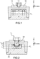
- FIG. 2 An example of a photosensitive device implemented according to an embodiment of the present invention is illustrated on the figures 2 and 3A-3C .
- the device is provided with a transistor T 1 coupled to a photosensitive zone 20.
- the transistor T 1 is formed on a semiconductor-on-insulator substrate and comprises a semiconductor support layer 10, an insulating layer 11 resting on a so-called "front face" of the support layer 10, and a layer superficial semiconductor 12 based on the insulating layer 11 and wherein the channel region of the first transistor T 1 is arranged.
- the substrate is, for example, of the SOI type (SOI for "Silicon on Insulator” or silicon on insulator), while the transistor T 1 is typically a MOS transistor (MOS for "Metal Oxide Semi-conductor") and can be produced, for example according to a totally deserted SOI technology - FDSOI (for "Fully Depleted Silicon On Insulator”).
- MOS Metal Oxide Semi-conductor
- the device is typically provided with isolation trenches 31, for example filled with silicon oxide, provided on either side of the transistor T 1 .
- the photosensitive zone 20 is in turn arranged in the support layer 10 and separated from the channel zone 14 of the transistor T 1 via the insulating layer 11 of the support.
- This insulating layer 11 is provided, in particular by its composition and its thickness, so as to allow the establishment of a capacitive coupling also called electrostatic coupling between the photosensitive zone and the channel zone 14 of the transistor.
- An exemplary embodiment provides an insulating layer 11 based on SiO 2 having a thickness which may be between 5 nm and 50 nm, preferably between 10 nm and 25 nm.
- the capacitive coupling is such that a variation of potential following the reception of a light radiation at the level of the photosensitive zone 20 can make it possible to generate a variation LIVS (with "LIVS” for "Light Induced V T Shift” or V-induced threshold voltage offset V T ) of the threshold voltage V T of the transistor T.
- LIVS with "LIVS” for "Light Induced V T Shift” or V-induced threshold voltage offset V T
- the variation of the threshold voltage V T of the transistor T 1 , following an illumination or a variation of illumination of the photosensitive zone 20 may for example reach a value of the order of 10mV to 250mV.
- this threshold voltage offset can be adjusted.
- a decrease in the thickness of the insulating layer 11, and / or an increase in the thickness of the superficial semiconductor layer 12, and / or an increase in the thickness of the gate dielectric of the transistors are particularly favorable to an increase in this threshold voltage shift.
- the photosensitive zone 20 is here formed of a first region 25 doped according to a given type of doping, for example an N type doping and a second region 27 doped according to another type of doping, opposite the given type of doping, in this example a P-type doping.
- a given type of doping for example an N type doping
- a second region 27 doped according to another type of doping, opposite the given type of doping, in this example a P-type doping.
- the photosensitive zone 20 is thus formed of at least one junction, whose arrangement in the support layer 10 is provided so as to allow a better concentration of photo-generated charges in the support layer 10 towards a given zone 24 of this layer 10 located against the insulating layer 11 and placed opposite the channel region 14 of the transistor.
- This given zone 24 has in this embodiment, a critical dimension Lnl measured in a plane parallel to the plane of the substrate equal to or substantially equal to that of the gate length Lg 18 of the transistor T 1 .
- "Main plane" of the substrate means a plane passing through the substrate and which is parallel to the plane [O; x; y] of the reference [O; x; y; z] given on the Figures 2A-2C and 3 .
- “Critical dimension” means the smallest dimension of an element except its thickness, this dimension being measured parallel to the plane [O; x; y].
- the gate length Lg is itself a dimension of the gate 18 of the transistor measured parallel to an axis passing through the source region and the drain region of the transistor T 1 , this axis also being parallel to the main plane of the substrate. So, the edges 25a of the first doped region 25 extend at least up to lateral sides 18a of the grid 18.
- the first doped region extends against the insulating layer 11 and facing the channel area 14.
- the channel zone 14 of the transistor is disposed entirely opposite the first doped region 25.
- the photosensitive device illustrated on the figures 2 and 3A-3C has an improved sensitivity due to a more efficient concentration of photo-generated charges to the given area 24 of the support layer located opposite the channel area 14.
- the 2D junction photosensitive device of the figure 1 allows to establish a uniform electric field in a plane parallel to the substrate.
- the photo-generated charges thus move in a substantially vertical direction (that is, substantially orthogonal to the main plane of the substrate). Therefore, photo-generated charges in portions of the support layer 10 that lie opposite the source 16 and drain 18 regions move to other portions of the support layer 10 which are also facing each other. source areas 16 and drain 18 but further near the insulating layer 11.
- Such a displacement is illustrated schematically by means of arrows F1.
- the improved concentration of the photo-generated charges in the device according to the invention is permitted because of an improved arrangement of the doped regions forming the junction.
- the second doped region 27 is in particular arranged on either side of the first region 25, and extends against the insulating layer 10 and facing source areas 16 and drain 18.
- the second doped region 27 also extends under the first doped region.
- a non-planar distribution, also called "3D" of the superposition of doped regions forming the junction is preferably provided.
- the junction is thus distributed over 3 dimensions and more particularly so that in a cross section of the support layer 10 (ie a section orthogonal to the main plane of the substrate), the first doped region 25 is entirely surrounded by said second doped region .
- the given zone 24 located against the insulating layer 11 opposite the channel zone 14 of the transistor thus sees a junction distributed around it.
- the first doped region 25 and the second doped region 27 are arranged concentrically around the given area 24.
- the junction has, in a plane orthogonal to a main plane of the substrate, a curved or curved profile around the given zone 24 of the support layer situated opposite the channel zone 14.
- the junction formed in the support layer 10 is preferably a PIN or NIP type junction, in order to optimize the collection of photo-generated charges by the absorption of photons in the space charge zone.
- an undoped or weakly doped intermediate region 29 which will serve as a depletion zone is preferably established.
- the lightly doped region may be a region that is doped by at least one electron accepting species and at least one electron donor species, the two species types compensating for low overall N doping. or P.
- weak or “weakly doped” is meant that the concentration of majority species is between 10 14 and 10 16 cm -3 .
- the second doped region 27 is in turn provided with a concentration typically between 17 and 19 / cm 3 , preferably between 18 and 5 18 / cm 3 .
- curves C 1 and C 2 are representative of variations of the parameter LIVS as a function of the optical power received and illustrate the performance respectively of a photosensitive structure with a NIP junction of "2D" type as illustrated on FIG. figure 1 and a structure according to the invention with a "3D” type PIN junction such as on the figure 2 .
- the insulating layer 11 of the substrate is silicon oxide with a thickness of the order of 25 nm.
- the transistor has a gate length Lg of the order of 60 nm, a width W of 1000 nm.
- the thickness Tn of the N-doped region under the BOX is of the order of 150 nm while the thickness Ti of the type-doped I-type region 29 is of the order of 100 nm (the thicknesses Ti, Tn being dimensions measured parallel to the z-axis.
- a 3D junction structure according to the invention makes it possible to achieve a performance improvement in terms of LIVS of the order of 80% compared with a 2D junction structure, at a low intensity of around 1e-7W / cm 2 .
- the dopant concentrations in the first doped region formed facing the channel area can be increased.
- the curves C 21 and C 22 are representative of the evolution of the LIVS parameter as a function of light intensity for 3D-type NIP-type photosensitive structures according to the invention respectively with a dopant concentration of the order of 1.75e18 / cm 3 and with a dopant concentration of the order of 1e19 / cm 3 in the first doped region 25.
- Such an increase in the concentration of dopants can make it possible to obtain a gain of about 80% of LIVS for an intensity of the order of 1e-7 W / cm 2 .
- the first region 25 is doped with a critical dimension L nl provided this time slightly greater than the gate length Lg of the transistor T 1 .
- the critical dimension L n1 is chosen to be less than a predetermined total length L max equal to to the grid length Lg added to a cumulative thickness 2 * ds of spacers 19 arranged on either side of the grid 18.
- the thickness ds of the spacers 19 just as the gate length Lg is a dimension measured parallel to the x axis of the [O; x; there; z].
- the critical dimension L n1 is provided such that Lg ⁇ L nl ⁇ Lg + 2 * ds.
- the excess ⁇ may be provided, for example, of the order of 60 nm.
- the curves C 200 and C 201 are representative of the evolution of the LIVS parameter as a function of the light intensity for photosensitive structures according to the invention with a critical dimension L nl of the first doped region 25 respectively equal to the length Lg gate of the transistor T 1 , and equal to Lg + 60 nm.
- L nl of the first doped region 25 respectively equal to the length Lg gate of the transistor T 1 , and equal to Lg + 60 nm.
- the curves C 110 , C 210 , and C 112 are representative of the evolution of the LIVS parameter as a function of the light intensity respectively for a junction-type photosensitive structure of the "2D" type as illustrated on FIG. figure 1 for a "3D” junction structure according to the invention and for a photosensitive zone structure 120 described as "2.5D” as illustrated in FIG. Figure 7B . They show the improved sensitivity conferred by the 3D layout of the junction.
- the photosensitive zone 120 is formed of a first doped region 125 facing the gate of the transistor, for example N-doped completely surrounded by a lightly doped or undoped type I region 129 and disposed on a P-doped layer 127.
- Steps of a method for producing a photosensitive device of the type described above are illustrated on the Figures 8A-8D .
- the photosensitive device is made from a semiconductor-on-insulator type substrate as evoked previously with a semiconductor layer 12 is superficial silicon.
- the semiconductor support layer 10 may also be silicon.
- This support layer 10 may be doped according to a given doping type, for example using an accepting species, in order to produce a well 13 having a P-type doping.
- P P-doped well 13
- Well type a P-doped well 13
- Indium implantation can be implemented.
- a step of the process illustrated on the figure 8A consists in producing a so-called "sacrificial" gate 58 of a transistor whose channel is provided in the surface layer 12.
- the sacrificial gate 58 is for example made of polysilicon or amorphous silicon and rests on a dielectric layer 57, for example made of SiO 2 , itself disposed on an area 14 of the surface layer 12 in which the channel is provided.
- an encapsulation layer 61 is formed around the sacrificial gate 58.
- the encapsulation layer 61 is typically an oxide layer deposited on the grid and then planarized by the CMP (Chemical Mechanical Planarization) method so as to remove a thickness of this layer and reveal the upper face of the sacrificial gate 58.
- the layer 61 encapsulation can be arranged around and against insulating spacers 19, for example silicon nitride, themselves arranged against lateral flanks of the sacrificial gate 58.
- a hard mask is provided on the sacrificial gate, then we can remove this hard mask selectively vis-à-vis the material of the encapsulation layer. Such selective shrinkage is achieved for example with orthophosphoric acid when the mask is silicon nitride and the encapsulation layer of silicon oxide.
- the sacrificial gate 58 is then removed so as to make an opening 63 in the form of the sacrificial gate 58.
- This removal can be carried out for example by etching with nitric acid or based on TMAH (Tetramethylammonium hydroxide) when the sacrificial gate 58 is polysilicon.
- TMAH Tetramethylammonium hydroxide
- the dielectric layer 57 is retained, which can then serve as a protective layer for the channel zone 14.
- a doping is performed by implantation of a portion 25 of the support layer 10 situated opposite the opening 63 and consequently of the channel zone 14.
- this implantation is carried out using a donor species in order to dopate a portion 25 having a doping opposite to that of the well 13, in this example a doping N. type
- the N-doped portion forms the first doped region of the junction and may be surrounded by a lightly doped intermediate region 29 enveloping this first region 25.
- the first region 25 thus has, in a plane parallel to the main plane of the substrate, dimensions that depend on those of the opening 63 and therefore the sacrificial gate removed.
- the N type doping is for example carried out using phosphorus using an implantation energy typically between 10 keV and 200 keV, preferably between 35 keV and 110 keV, in a dose typically between 1e12cm -2 and 1e14cm -2 , preferably between 1.2e13cm -2 and 4e13cm -2
- Another exemplary embodiment provides an Arsenic implantation with an energy that can be between 10 keV and 200 keV, preferably between 80 keV and 110 keV, with a dose typically between 12 cm -2 and 1e14 cm -2 , preferably between 5e12 cm -2 and 5e13 cm -2 .
- an energy that can be between 10 keV and 200 keV, preferably between 80 keV and 110 keV, with a dose typically between 12 cm -2 and 1e14 cm -2 , preferably between 5e12 cm -2 and 5e13 cm -2 .
- a replacement gate 18 can then be formed by depositing a gate dielectric and then a gate material in the opening 63.
- the grid has, in a plane parallel to the main plane of the substrate, dimensions that correspond to those of the sacrificial gate previously removed.
- the first region 25 has in particular a critical dimension LnI which corresponds substantially to the length Lg of the grid 18.
- the exemplary method which has just been described concerns the production of a PIN or PN junction with an N-doped region 25 coated with a P-doped region.
- NIP or NP junction with an N-doped region 25 coated with a P-doped region 27 can be made.
- an N-type well 13 is produced, for example by implantation using Phosphorus, with an energy typically between 100 keV and 300 keV, preferably between 155 keV and 240 keV, in a dose typically chosen between 1e12cm -2 and 1e14cm -2 , preferably between 1.2e12cm -2 and 4e13cm -2 .
- the implementation described above in connection with the Figure 8B is an acceptor species implantation to form a first P-doped region.
- a P-doped region it is possible, for example, to perform an Indium-based implantation with an energy of between 100 keV and 300 keV, preferably between 130 keV and 200 keV, with a dose typically between 1e12cm -2 and 1e14cm -2 , preferably between 5e12cm -2 and 5e13cm -2 .
- the P-type doping of the region 25 is carried out by performing a boron-based implantation with an energy typically between 1 keV and 5 keV, preferably between 10 keV and 40 keV, with a typically scheduled dose. between 1e12cm -2 and 1e14cm -2 , preferably between 5e12cm -2 and 5e13cm -2 .
- Another example of a method provides, unlike the previous example, an embodiment of the gate of the transistor before forming the junction.
- N-type doping of portions 64 of the support layer 10 located under the grids 18 is carried out.
- Implantation is performed using a first doping species, in the example of the figure 11A an accepting species of electrons.
- the angle ⁇ 1 is chosen according to the dimensions of the grid. Typically, an implantation angle ⁇ 1 of between 0 and 40 ° is provided.
- At least one other implantation inclined at an angle - ⁇ 2 is then performed with respect to a face F 2 of the given plane P opposite to the first face F 1 .
- the angles ⁇ 1 and ⁇ 2 equal so that the implantation bundles are symmetrical with respect to the plane P.
- the N-type doped portions 64 are widened so that they extend entirely opposite each other. Grids 18. Typically, 0 ⁇ 1 ⁇ 40 ° is provided.
- a vertical implantation step is then performed, that is to say performed this time parallel to the given plane P.
- the doping is carried out using a second doping species which is an electron-donating species when the first doping species is an electron-accepting species, and an electron-accepting species when the first doping species is an electron donating species.
- P-type implantation is carried out so as to shrink the N-type doped portions 64 and form around the doped portions 65 in a P-type doping.
- the doping may be similar to that performed to produce the well 13. P-doped, but with a lower implantation energy.
- the first doped region of the photosensitive area is formed of the N-doped portion 64 while the second doped region 27 is formed of the implanted portions 65 and the P-doped well 13.
- FIG. 10A-10C Another example of a process for producing the photosensitive zone is illustrated on the Figures 10A-10C .
- one or more grids 18 of transistors are formed ( figure 10A ).
- first implantations inclined respectively according to angles ⁇ ' 1 and - ⁇ ' 1 are carried out with respect to a given plane P orthogonal to the main plane of the substrate, and which extends in the direction of its width of the grid 18.
- a given plane P orthogonal to the main plane of the substrate, and which extends in the direction of its width of the grid 18.
- an angle ⁇ ' 1 of the order of 30 ° can be provided.
- a portion 66 of the support layer 10 facing the gate 18 is doped and N-type doping of this portion 66 is performed ( figure 10B ).
- ⁇ ' 2 may be of the order of 0 to 30 °
- Another embodiment of the photosensitive zone provides for forming a PN or NP vertical junction before forming one or more transistor gates 18.
- An ion implantation is then carried out so as to doping an upper sub-layer 68 of the support layer 10 ( figure 11A ).
- the upper sub-layer 68 is arranged against the insulating layer 11 and extends parallel to the main plane of the substrate.
- the doping carried out is of the opposite type to that of the doped well 13.
- opposite type doping is meant that the upper sub-layer 68 is doped with N-type doping when the well 13 is P-doped (and conversely that the upper sub-layer 68 is doped with P-type doping when the well 13 is doped N).
- the portions 69 are p-doped. These portions 69 are N-doped when the upper sub-layer 68 is P-doped ( figure 11C ).
- a doped portion N located under the gate 18 and protected by the latter during the implantation retains the same doping as that initially made in the upper layer 68, for example an N-type doping when the portions 69 are p-doped.
- Semiconductor blocks may then be formed on the surface layer 12 on either side of the gate 18 so as to form source and drain regions opposite the P-doped portions 69.
- At least one other implantation is performed so as to perform a P-type doping or increase the P-doping of portions 83 of the lightly doped portions 79.
- This other implementation is preferably implemented using a masking layer 81 in particular arranged against the sidewalls of the grid.
- This masking layer may be based for example on silicon nitride (preferentially deposited by a conformal deposition method such as ALD ("Atomic Layer Deposition”) and makes it possible to protect weakly doped zones 79a of the support layer arranged between the doped portion N located opposite the gate and the doped portions P disposed on either side of this N-doped portion 70 (FIG. figure 12B ).
Abstract
La demande concerne un dispositif photosensible à transistor (T 1 ), sur substrat semi-conducteur sur isolant, la zone photosensible (20) étant formée dans la couche de support du substrat et étant agencée de manière à permettre d'augmenter la concentration de charges photo-générées dans la zone photosensible vers une zone donnée située en regard de la zone de canal du transistor.The application relates to a photosensitive transistor device (T 1) on a semiconductor-on-insulator substrate, the photosensitive area (20) being formed in the support layer of the substrate and being arranged so as to make it possible to increase the concentration of charges. photo-generated in the photosensitive zone to a given area located next to the channel region of the transistor.
Description
La présente invention se rapporte au domaine de la photo-détection et de l'imagerie et concerne la mise en oeuvre d'un dispositif de photo-détection amélioré sur un substrat de type semi-conducteur sur isolant.The present invention relates to the field of photo-detection and imaging and relates to the implementation of an improved photo-detection device on a semiconductor-on-insulator substrate.
Dans le domaine technique des dispositifs photosensibles, le document
Il se pose le problème d'améliorer la sensibilité de détection d'un tel type de dispositif microélectronique photosensible.There is the problem of improving the detection sensitivity of such a type of photosensitive microelectronic device.
Un mode de réalisation de la présente demande prévoit un dispositif photosensible comprenant un substrat semi-conducteur sur isolant sur lequel repose au moins un transistor, le substrat étant doté d'une couche semi-conductrice superficielle dans laquelle une zone de canal dudit transistor est agencée, d'une couche isolante séparant la couche semi-conductrice superficielle d'une couche de support semi-conductrice, la couche de support semi-conductrice comprenant une zone photosensible formée de régions dopées respectivement selon au moins un dopage d'un premier type, N ou P, et au moins un dopage d'un deuxième type, P ou N, de sorte à former au moins une jonction, la couche isolante étant configurée de manière à permettre un couplage capacitif entre la zone photosensible et la zone de canal du transistor,
les régions dopées formant la jonction étant agencées par rapport à une zone donnée de la couche de support située contre la couche isolante et en regard de la zone de canal du transistor, de sorte à concentrer des charges photo-générées dans la couche de support dans des parties situées en regard des zones de source et de drain en direction de cette zone donnée.One embodiment of the present application provides a photosensitive device comprising a semiconductor-on-insulator substrate on which at least one transistor rests, the substrate being provided with a superficial semiconductor layer in which a channel zone of said transistor is arranged. an insulating layer separating the superficial semiconductor layer from a semiconductor carrier layer, the semiconductor support layer comprising a photosensitive zone formed of regions doped respectively according to at least one doping of a first type, N or P, and at least one doping of a second type, P or N, so as to form at least one junction, the insulating layer being configured to allow capacitive coupling between the photosensitive zone and the channel zone of the transistor,
the junction-forming doped regions being arranged with respect to a given region of the support layer located against the insulating layer and facing the channel region of the transistor, so as to concentrate photo-generated charges in the support layer in parts located opposite the source and drain zones towards this given zone.
En particulier, la jonction peut être formée d'une superposition de régions dopées ayant un profil 3D ou non-planaire, réparties autour de ladite zone donnée en régions concentriques.In particular, the junction may be formed of a superposition of doped regions having a 3D or non-planar profile, distributed around said given area in concentric regions.
Selon un mode de réalisation, la zone photosensible comporte parmi lesdites régions dopées:
- une première région dopée selon un dopage d'un premier type, N ou P, la première région dopée étant agencée contre la couche isolante et étant située et en regard de la zone de canal,
- une deuxième région dopée selon un dopage d'un deuxième type, P ou N, la deuxième région dopée étant disposée autour de la première région dopée et s'étendant contre la couche isolante et en regard des zones de source et de drain.
- a first region doped with a doping of a first type, N or P, the first doped region being arranged against the insulating layer and being located and facing the channel zone,
- a doped second doping region of a second type, P or N, the second doped region being disposed around the first doped region and extending against the insulating layer and facing the source and drain areas.
On forme ainsi, une ou plusieurs jonctions ou portions de jonctions PN ou NP ou PIN ou NIP horizontales autrement dit parallèles au plan principal du substrat et configurées de sorte à pouvoir ramener des charges photo-générées dans la couche de support en face des zones de source et de drain vers une zone donnée de la couche de support située quant à elle en face de la zone de canal. Cette meilleure concentration de charges photo-générées en regard du canal permet d'augmenter la sensibilité de détection du dispositif.One or more junctions or portions of horizontal PN or NP or PIN or NIP junctions are thus formed, in other words parallel to the main plane of the substrate and configured so as to be able to bring back photo-generated charges into the support layer in front of the source and drain to a given area of the support layer located opposite the channel area. This better concentration of photo-generated charges facing the channel makes it possible to increase the detection sensitivity of the device.
De préférence, la deuxième région dopée s'étend en outre sous la première région dopée, de sorte qu'en regard de la zone de canal, la première région dopée se situe entre la couche isolante et la deuxième région dopée. La zone photosensible comporte dans ce cas une jonction ou portion de jonction PN ou NP ou PIN ou NIP à agencement vertical.Preferably, the second doped region further extends under the first doped region, so that next to the channel zone, the first doped region lies between the insulating layer and the second doped region. In this case, the photosensitive zone comprises a junction or PN or NP or PIN or NIP junction portion with a vertical arrangement.
Avantageusement, la zone de canal du transistor est agencée entièrement en regard de la première région dopée.Advantageously, the channel zone of the transistor is arranged entirely opposite the first doped region.
Avantageusement, dans une section transversale de la couche de support, la première région dopée est entièrement entourée par ladite deuxième région dopée. La zone donnée de la couche de support située en regard du canal est ainsi entièrement entourée d'une jonction PN ou NP ou PIN ou NIPAdvantageously, in a cross section of the support layer, the first doped region is entirely surrounded by said second doped region. The given area of the support layer located next to the channel is thus completely surrounded by a PN or NP junction or PIN or PIN
De préférence, une région intermédiaire faiblement dopée est disposée entre ladite première région dopée et ladite deuxième région dopée, de sorte à former une jonction de type PIN ou NIP.Preferably, a weakly doped intermediate region is disposed between said first doped region and said second doped region, so as to form a PIN or NIP type junction.
Avantageusement, la première région dopée, la région intermédiaire et la deuxième région dopée forment une jonction de type PIN ou NIP et sont réparties de manière concentrique autour de la zone donnée de la couche de support située entièrement en regard de la zone de canal du transistor et contre la couche isolante.Advantageously, the first doped region, the intermediate region and the second doped region form a PIN or NIP junction and are distributed concentrically around the given area of the support layer situated entirely opposite the channel zone of the transistor. and against the insulating layer.
Pour améliorer davantage la sensibilité du dispositif, on peut prévoir une première région avec une largeur prévue légèrement supérieure à la longueur de grille du transistor.To further improve the sensitivity of the device, a first region may be provided with a width slightly greater than the gate length of the transistor.
La première région dopée peut être ainsi délimitée latéralement par des bords latéraux disposés en regard d'espaceurs isolants agencés contre la grille.The first doped region may thus be delimited laterally by lateral edges arranged facing insulating spacers arranged against the grid.
Un autre aspect de la présente invention concerne un procédé de réalisation de la zone photosensible à agencement non-planaire ou 3D des régions dopées.Another aspect of the present invention relates to a method for producing the non-planar or 3D photosensitive zone of the doped regions.
Un mode de réalisation du procédé de mise en oeuvre d'une zone photosensible pour un dispositif tel que décrit précédemment prévoit, à partir d'un substrat dans lequel la couche de support du substrat est dopée selon le dopage du deuxième type, P ou N, des étapes de :
- réalisation sur le substrat d'une grille sacrificielle et d'un masque autour de la grille sacrificielle,
- retrait de la grille sacrificielle de sorte à former une ouverture entourée par le masque,
- implantation à travers l'ouverture, de sorte à doper selon le premier type de dopage N ou P, une portion de la couche de support disposée en regard de l'ouverture.
- realization on the substrate of a sacrificial gate and a mask around the sacrificial gate,
- removing the sacrificial gate so as to form an opening surrounded by the mask,
- implantation through the opening, so as to doping according to the first type of N or P doping, a portion of the support layer disposed opposite the opening.
La portion dopée a ainsi avantageusement des dimensions qui dépendent de celles de la grille sacrificielle. Ensuite, si l'on forme dans l'ouverture une grille de remplacement, les dimensions de la portion dopée dépendent également de celle de la grille de remplacement. Ladite portion dopée correspond typiquement à la première région dopée du dispositif défini plus haut.The doped portion thus advantageously has dimensions that depend on those of the sacrificial gate. Then, if a replacement grid is formed in the opening, the dimensions of the doped portion also depend on that of the replacement grid. Said doped portion typically corresponds to the first doped region of the device defined above.
Un autre mode de réalisation prévoit un procédé de mise en oeuvre de la zone photosensible pour un dispositif photosensible tel que décrit précédemment à partir d'un substrat dans lequel la couche de support du substrat est dopée selon le dopage du deuxième type, P ou N, le procédé comprenant les étapes de :
- implantations inclinées, respectivement selon un angle α1 et un angle
- α2 par rapport à un plan donné orthogonal au plan principal du substrat, de sorte à doper selon un dopage du premier type une première portion de la couche de support en regard de la grille,
- implantation parallèlement au plan donné de sorte à doper selon le dopage du deuxième type des deuxièmes portions de la couche de support de part et d'autre de la première portion. α1 et α2 sont des angles non-nuls et typiquement égaux.
- inclined implantations, respectively according to an angle α 1 and an angle
- α 2 with respect to a given plane orthogonal to the main plane of the substrate, so as to doping in a doping of the first type a first portion of the support layer facing the grid,
- implantation parallel to the given plane so as to doping according to the doping of the second type of the second portions of the support layer on either side of the first portion. α 1 and α 2 are non-zero and typically equal angles.
Un autre mode de réalisation du procédé de mise en oeuvre de la zone photosensible dans lequel une grille de transistor est formée sur le substrat semi-conducteur sur isolant, la couche de support du substrat étant dopée selon le dopage du deuxième type, par exemple de type P, prévoit :
- des premières implantations inclinées respectivement selon des angles α1 et -α1 par rapport à un plan donné orthogonal au plan principal du substrat, de sorte à doper sous la grille une portion de la couche de support selon un dopage d'un premier type, par exemple de type N.
- des deuxièmes implantations inclinées selon respectivement des angles α2, -α2 tels que α2 < α1 par rapport au plan donné de sorte à augmenter la profondeur de ladite portion dopée ayant un dopage du premier type.
- first implantations respectively inclined at angles α 1 and -α 1 with respect to a given plane orthogonal to the main plane of the substrate, so as to dope a portion of the support layer with a doping of a first type under the grid, for example type N.
- second implantations inclined respectively according to angles α 2 , -α 2 such that α 2 <α 1 with respect to the given plane so as to increase the depth of said doped portion having a doping of the first type.
Un autre mode de réalisation du procédé dans lequel la couche de support est initialement dopée selon le dopage du deuxième type, par exemple de type P, comprend les étapes de :
- implantation de sorte à doper une sous-couche supérieure de la couche de support selon un dopage du premier type, puis
- formation d'une grille, puis,
- implantation de part et d'autre de la grille, de sorte à doper selon le dopage du deuxième type des portions de la couche de support situées de part et d'autre d'une portion centrale agencée en regard de la grille.
- implantation so as to dope an upper sub-layer of the support layer in a doping of the first type, then
- forming a grid, then,
- implantation on either side of the grid, so as to doping according to the doping of the second type of portions of the support layer located on either side of a central portion arranged opposite the grid.
Avantageusement, après implantation des portions on forme une couche de masquage contre des flancs de la grille, puis on réalise au moins une nouvelle implantation de part et d'autre de la grille de sorte à augmenter le dopage du deuxième type de certaines parties desdites portions.Advantageously, after implantation of the portions, a masking layer is formed against flanks of the gate, then at least one new implantation is made on either side of the gate so as to increase the doping of the second type of certain portions of said portions. .
La présente invention sera mieux comprise à la lecture de la description d'exemples de réalisation donnés, à titre purement indicatif et nullement limitatif, en faisant référence aux dessins annexés sur lesquels :
- la
figure 1 sert à illustrer un dispositif photosensible à transistor formé sur un substrat semi-conducteur sur isolant et doté d'une jonction à agencement 2D disposée en regard du transistor dans la couche de support du substrat, la jonction ayant un agencement planaire 2D ; - les
figures 2 ,3A-3C servent à illustrer un exemple de dispositif photosensible selon un mode de réalisation de la présente invention doté d'un transistor formé sur un substrat semi-conducteur sur isolant et, dans la couche de support du substrat, d'une jonction à agencement 3D permettant de concentrer des charges photo-générées essentiellement dans une zone donnée de la couche de support située en regard de la zone de canal du transistor ; - les
figures 4A-4B servent à illustrer des différences de performances en termes du décalage de tensions de seuil induit par la lumière (LIVS) entre un dispositif photosensible à jonction 2D tel que sur lafigure 1 et un dispositif photosensible à jonction 3D tel que sur lesfigures 3A-3C ; - la
figure 5 sert à illustrer des différences de performances en termes de LIVS entre deux dispositifs photosensibles à jonction 3D ayant des niveaux de dopages différents de la première région dopée de la zone photosensible ; - les
figures 6A-6B servent à illustrer une variante de mise en oeuvre de dispositif suivant l'invention à jonction 3D formée d'une zone dopée qui s'étend en regard du canal et de la grille du transistor et dont les limites latérales sont situées en regard des espaceurs ; - les
figures 7A-7B servent à illustrer des différences de sensibilité entre un dispositif photosensible muni d'une jonction 3D telle que mise en oeuvre suivant l'invention et d'autres types d'agencements ; - les
figures 8A-8D servent à illustrer des étapes d'un premier exemple de procédé de réalisation d'un dispositif photosensible suivant l'invention ; - les
figures 9A-9C servent à illustrer des étapes d'un deuxième exemple de procédé de réalisation d'un dispositif photosensible suivant l'invention ; - les
figures 10A-10C servent à illustrer des étapes d'un troisième exemple de procédé de réalisation d'un dispositif photosensible suivant l'invention ; - les
figures 11A-11C servent à illustrer des étapes d'un quatrième exemple de procédé de réalisation d'un dispositif photosensible suivant l'invention ; - les
figures 12A-12B servent à illustrer une variante de mise en oeuvre du quatrième exemple de procédé ;
- the
figure 1 is for illustrating a transistor photosensitive device formed on a semiconductor-on-insulator substrate and having a 2D arrangement junction disposed facing the transistor in the substrate support layer, the junction having a 2D planar arrangement; - the
figures 2 ,3A-3C are used to illustrate an example of a photosensitive device according to an embodiment of the present invention having a transistor formed on a semiconductor-on-insulator substrate and, in the support layer of the substrate, a junction with a 3D arrangement allowing focus photo-generated charges essentially in a given area of the support layer located opposite the channel area of the transistor; - the
Figures 4A-4B are used to illustrate differences in performance in terms of light-induced threshold voltage shift (LIVS) between a 2D junction light-sensitive device such as thefigure 1 and a photosensitive device with a 3D junction such as on theFigures 3A-3C ; - the
figure 5 is used to illustrate LIVS performance differences between two 3D junction photosensitive devices having doping levels different from the first doped region of the photosensitive area; - the
Figures 6A-6B are used to illustrate an alternative embodiment of device according to the invention with a 3D junction formed of a doped zone which extends opposite the channel and the gate of the transistor and whose lateral limits are located opposite the spacers; - the
Figures 7A-7B serve to illustrate differences in sensitivity between a photosensitive device provided with a 3D junction as implemented according to the invention and other types of arrangements; - the
Figures 8A-8D serve to illustrate steps of a first example of a method for producing a photosensitive device according to the invention; - the
Figures 9A-9C are used to illustrate steps of a second example of a method for producing a photosensitive device according to the invention; - the
Figures 10A-10C serve to illustrate steps of a third example of a method for producing a photosensitive device according to the invention; - the
Figures 11A-11C serve to illustrate steps of a fourth example of a method for producing a photosensitive device according to the invention; - the
Figures 12A-12B serve to illustrate an alternative embodiment of the fourth example method;
Des parties identiques, similaires ou équivalentes des différentes figures portent les mêmes références numériques de façon à faciliter le passage d'une figure à l'autre.Identical, similar or equivalent parts of the different figures bear the same numerical references so as to facilitate the passage from one figure to another.
Les différentes parties représentées sur les figures ne le sont pas nécessairement selon une échelle uniforme, pour rendre les figures plus lisibles.The different parts shown in the figures are not necessarily in a uniform scale, to make the figures more readable.
Un exemple de dispositif photosensible mis en oeuvre suivant un mode de réalisation de la présente invention est illustré sur les
Le dispositif est doté d'un transistor T1 couplé à une zone photosensible 20.The device is provided with a transistor T 1 coupled to a
Le transistor T1 est formé sur un substrat de type semi-conducteur sur isolant et comprend une couche de support 10 semi-conductrice, une couche isolante 11 reposant sur une face dite « face avant » de la couche de support 10, et une couche semi-conductrice 12 superficielle reposant sur la couche isolante 11 et dans laquelle la zone de canal du premier transistor T1 est agencée.The transistor T 1 is formed on a semiconductor-on-insulator substrate and comprises a
Le substrat est par exemple de type SOI (SOI pour « Silicon on Insulator » ou silicium sur isolant), tandis que le transistor T1 est typiquement un transistor MOS (MOS pour « Metal Oxide Semi-conductor ») et peut être réalisé par exemple selon une technologie de type SOI totalement désertée - FDSOI (pour « Fully Depleted Silicon On Insulator »). Le dispositif est typiquement muni de tranchées d'isolation 31 par exemple remplies d'oxyde de silicium, prévues de part et d'autre du transistor T1.The substrate is, for example, of the SOI type (SOI for "Silicon on Insulator" or silicon on insulator), while the transistor T 1 is typically a MOS transistor (MOS for "Metal Oxide Semi-conductor") and can be produced, for example according to a totally deserted SOI technology - FDSOI (for "Fully Depleted Silicon On Insulator"). The device is typically provided with
La zone photosensible 20 est quant à elle agencée dans la couche de support 10 et séparée de la zone de canal 14 du transistor T1 par l'intermédiaire de la couche isolante 11 du support. Cette couche isolante 11 est prévue, en particulier de par sa composition et son épaisseur, de manière à permettre l'établissement d'un couplage capacitif également appelé couplage électrostatique entre la zone photosensible et la zone de canal 14 du transistor. Un exemple de réalisation prévoit une couche isolante 11 à base de SiO2 ayant une épaisseur qui peut être comprise entre 5nm et 50nm, de préférence entre 10nm et 25nm.The
Le couplage capacitif est tel qu'une variation de potentiel consécutive à la réception d'un rayonnement lumineux au niveau de la zone photosensible 20 peut permettre de générer une variation LIVS (avec « LIVS » pour « Light Induced VT Shift » ou décalage de tension de seuil VT induite par la lumière) de la tension de seuil VT du transistor T.The capacitive coupling is such that a variation of potential following the reception of a light radiation at the level of the
La variation de tension de seuil VT du transistor T1, consécutive à un éclairement ou une variation d'éclairement de la zone photosensible 20 peut par exemple atteindre une valeur de l'ordre de 10mV à 250mV.The variation of the threshold voltage V T of the transistor T 1 , following an illumination or a variation of illumination of the
En adaptant les épaisseurs respectives de la couche isolante 101, et/ou de la couche semi-conductrice superficielle 12, et/ou du diélectrique de grille du transistor on peut ajuster ce décalage de tension de seuil.By adapting the respective thicknesses of the insulating layer 101, and / or the
Une diminution de l'épaisseur de la couche isolante 11, et/ou une augmentation de l'épaisseur de la couche semi-conductrice superficielle 12, et/ou une augmentation de l'épaisseur du diélectrique de grille des transistors sont en particulier favorables à une augmentation de ce décalage de tension de seuil.A decrease in the thickness of the insulating
La zone photosensible 20 est ici formée d'une première région 25 dopée selon un type de dopage donné, par exemple un dopage de type N et d'une deuxième région 27 dopée selon un autre type de dopage, opposé au type de dopage donné, dans cet exemple un dopage de type P.The
La zone photosensible 20 est ainsi formée d'au moins une jonction, dont l'agencement dans la couche de support 10 est prévu de sorte à permettre une meilleure concentration de charges photo-générées dans la couche de support 10 vers une zone donnée 24 de cette couche 10 située contre la couche isolante 11 et placée en regard de la zone 14 de canal du transistor. Cette zone donnée 24 a dans cet exemple de réalisation, une dimension critique Lnl mesurée dans un plan parallèle au plan du substrat égale ou sensiblement égale à celle de la longueur Lg de grille 18 du transistor T1. Par « plan principal » du substrat, on entend un plan passant par le substrat et qui est parallèle au plan [O ;x ;y] du repère [O ;x ;y ;z] donné sur les
Par « dimension critique » on entend la plus petite dimension d'un élément hormis son épaisseur, cette dimension étant mesurée parallèlement au plan [O ;x ;y]. La longueur de grille Lg est quant à elle une dimension de la grille 18 du transistor mesurée parallèlement à un axe passant par la région de source et la région de drain du transistor T1, cet axe étant également parallèle au plan principal du substrat. Ainsi, les bords latéraux 25a de la première région dopée 25 s'étendent au moins jusqu'en regard de flancs latéraux 18a de la grille 18."Critical dimension" means the smallest dimension of an element except its thickness, this dimension being measured parallel to the plane [O; x; y]. The gate length Lg is itself a dimension of the
La première région 25 dopée s'étend contre la couche isolante 11 et en regard de la zone 14 de canal. De préférence, la zone 14 de canal du transistor est disposée entièrement en regard de la première région dopée 25.The first doped region extends against the insulating
Par rapport à un agencement qualifié de « 2D » du type de celui de la
Le dispositif photosensible à jonction 2D de la
La concentration améliorée des charges photo-générées dans le dispositif suivant l'invention est permise du fait d'un agencement amélioré des régions dopées formant la jonction.The improved concentration of the photo-generated charges in the device according to the invention is permitted because of an improved arrangement of the doped regions forming the junction.
La deuxième région dopée 27 est en particulier agencée de part et d'autre de la première région 25, et s'étend contre la couche isolante 10 et en regard des zones de source 16 et de drain 18.The second
Ainsi, de par une telle répartition des régions 25 et 27, des charges photo-générées dans des parties de la couche de support 10 qui se situent en regard des zone de source 16 et de drain 18 sont susceptibles d'être déplacées vers la zone donnée 24 de la couche de support 10 qui se trouve en regard de la zone de canal 14 et a des dimensions dans un plan parallèle au plan du substrat égales ou sensiblement égales à celles de la grille 18 du transistor T1.Thus, by such a distribution of the
Avantageusement, la deuxième région 27 dopée s'étend également sous la première région 25 dopée.Advantageously, the second
On prévoit ainsi de préférence une répartition, non-planaire, encore qualifiée de « 3D », de la superposition de régions dopées formant la jonction.Thus, a non-planar distribution, also called "3D", of the superposition of doped regions forming the junction is preferably provided.
Dans l'exemple particulier des
Dans ce mode de réalisation particulier, la jonction a, dans un plan orthogonal à un plan principal du substrat, un profil incurvé ou recourbé autour de la zone donnée 24 de la couche de support située en regard de la zone 14 de canal.In this particular embodiment, the junction has, in a plane orthogonal to a main plane of the substrate, a curved or curved profile around the given
Du fait d'un tel agencement de la jonction on peut obtenir un déplacement des charges photo-générées tel que sur la
La jonction formée dans la couche de support 10 est de préférence une jonction de type PIN ou NIP, afin d'optimiser la collection de charges photo-générées par l'absorption de photons dans la zone de charge d'espace.The junction formed in the
Ainsi entre la première région dopée 25 et la deuxième région dopée 27, une région 29 intermédiaire non-dopée ou faiblement dopée qui servira de zone de déplétion est de préférence établie.Thus between the first
La région faiblement dopée peut être une région à la fois dopée par au moins une espèce accepteuse d'électrons et au moins une espèce donneuse d'électrons, les deux types d'espèces se compensant de sorte à créer un dopage global faible de type N ou P. Par « faible » ou « faiblement dopé », on entend que la concentration d'espèce majoritaire est comprise entre 1014 et 1016 cm-3.The lightly doped region may be a region that is doped by at least one electron accepting species and at least one electron donor species, the two species types compensating for low overall N doping. or P. By "weak" or "weakly doped" is meant that the concentration of majority species is between 10 14 and 10 16 cm -3 .
La deuxième région dopée 27 est quant à elle prévue avec une concentration typiquement entre 1e17 et 1e19/cm3 de préférence entre 1e18 et 5e18/cm3.The second
Sur la
Comme cela est illustré sur la
Pour améliorer les performances d'une structure à jonction 3D telle que décrite précédemment, on peut augmenter les concentrations de dopants dans la première région 25 dopée formée en regard de la zone de canal.To improve the performance of a 3D junction structure as described above, the dopant concentrations in the first doped region formed facing the channel area can be increased.
Sur la
Afin d'améliorer la sensibilité de détection, on peut également prévoir une variante de réalisation telle qu'illustrée sur la
Par « légèrement supérieure » on entend que le dépassement δ par rapport la longueur de grille est inférieur à 40nm et prévu inférieur à l'épaisseur des espaceurs 19. Ainsi, la dimension critique Lnl est choisie inférieure à une longueur totale Lmax prédéterminée égale à la longueur de grille Lg additionnée à une épaisseur cumulée 2*ds d'espaceurs 19 disposés de part et d'autre la grille 18. L'épaisseur ds des espaceurs 19 tout comme la longueur de grille Lg est une dimension mesurée parallèlement à l'axe x du repère [O; x; y; z]. Autrement dit, on prévoit la dimension critique Lnl telle que Lg ≤ Lnl < Lg + 2*ds.By "slightly greater" is meant that the excess δ with respect to the gate length is less than 40 nm and is smaller than the thickness of the
Pour une grille de dimension par exemple de l'ordre de 30nm le dépassement δ peut être prévu par exemple de l'ordre de 60nm.For a dimension grid, for example of the order of 30 nm, the excess δ may be provided, for example, of the order of 60 nm.
Sur la
Sur la
Dans l'agencement 2.5D de la
Des étapes d'un procédé de réalisation d'un dispositif photosensible du type de celui décrit précédemment sont illustrées sur les
Le dispositif photosensible est réalisé à partir d'un substrat de type semi-conducteur sur isolant tel qu'évoqué précédemment avec une couche semi-conductrice 12 superficielle est en silicium. La couche de support 10 semi-conductrice peut également être en silicium.The photosensitive device is made from a semiconductor-on-insulator type substrate as evoked previously with a
Cette couche de support 10 peut être dopée selon un type de dopage donné, par exemple à l'aide d'une espèce accepteuse, afin de réaliser un puits 13 ayant un dopage de type P. Pour former un puits 13 dopé P (« P-type Well ») dans la couche de support 10, on peut effectuer une implantation de Bore selon une énergie comprise typiquement entre 30 keV et 250 keV, de préférence entre 120 keV and 200 keV, et une dose typiquement comprise entre 1e12 cm-2 et 1e14 cm-2, de préférence entre 1.2e12 cm-2 et 4e13 cm-2. En variante, une implantation d'Indium peut être mise en oeuvre.This
Une étape du procédé illustrée sur la
Autour de la grille sacrificielle 58, une couche 61 d'encapsulation est formée. La couche 61 d'encapsulation est typiquement une couche d'oxyde déposée sur la grille puis planarisée par procédé CMP (Chemical Mechanical Planarisation) de sorte à retirer une épaisseur de cette couche et dévoiler la face supérieure de la grille sacrificielle 58. La couche 61 d'encapsulation peut être disposé autour et contre des espaceurs isolants 19, par exemple en nitrure de silicium, eux-mêmes agencés contre des flancs latéraux de la grille sacrificielle 58. Lorsqu'un masque dur est prévu sur la grille sacrificielle, on peut alors retirer ce masque dur sélectivement vis-à-vis du matériau de la couche d'encapsulation. Un tel retrait sélectif est réalisé par exemple avec de l'acide orthophosphorique lorsque le masque du est en nitrure de silicium et la couche d'encapsulation en oxyde de silicium.Around the
La grille sacrificielle 58 est ensuite retirée de sorte à réaliser une ouverture 63 prenant la forme de la grille sacrificielle 58. Ce retrait peut être effectué par exemple par gravure à l'aide d'acide nitrique ou à base de TMAH (Tetramethylammonium hydroxide) lorsque la grille sacrificielle 58 est en polysilicium.The
Avantageusement, à ce stade du procédé, on conserve la couche diélectrique 57 qui pourra servir ensuite de couche de protection de la zone 14 de canal.Advantageously, at this stage of the process, the
Puis, on effectue un dopage par implantation d'une portion 25 de la couche de support 10 située en regard de l'ouverture 63 et par conséquent de la zone de canal 14. Dans le cas illustré sur la
La portion 25 dopée N forme la première région dopée de la jonction et peut être entourée d'une région intermédiaire 29 faiblement dopée enveloppant cette première région 25.The N-doped portion forms the first doped region of the junction and may be surrounded by a lightly doped
La première région 25 a ainsi, dans un plan parallèle au plan principal du substrat, des dimensions qui dépendent de celles de l'ouverture 63 et donc de la grille sacrificielle retirée.The
Le dopage de type N est par exemple effectué à l'aide de Phosphore en utilisant une énergie d'implantation typiquement comprise entre 10 keV et 200 keV, de préférence entre 35 keV et 110 keV, selon une dose typiquement comprise entre 1e12cm-2 et 1e14cm-2, de préférence entre 1.2e13cm-2 et 4e13cm-2 The N type doping is for example carried out using phosphorus using an implantation energy typically between 10 keV and 200 keV, preferably between 35 keV and 110 keV, in a dose typically between 1e12cm -2 and 1e14cm -2 , preferably between 1.2e13cm -2 and 4e13cm -2
Un autre exemple de réalisation prévoit une implantation d'Arsenic selon une énergie qui peut être comprise entre 10 keV et 200 keV, de préférence entre 80 keV et 110 keV, avec une dose typiquement comprise entre 1e12 cm-2 et 1e14 cm-2, de préférence entre 5e12 cm-2 et 5e13 cm-2. Lorsque la couche de diélectrique 57 de grille a été conservée, celle-ci permet alors de protéger la zone 14 de canal lors de l'implantation. Les portions du puits 13 dopé qui gardent un dopage globalement de type P forment la deuxième région dopée 27 enveloppant la région intermédiaire 29.Another exemplary embodiment provides an Arsenic implantation with an energy that can be between 10 keV and 200 keV, preferably between 80 keV and 110 keV, with a dose typically between 12 cm -2 and 1e14 cm -2 , preferably between 5e12 cm -2 and 5e13 cm -2 . When the
Lors d'une étape ultérieure illustrée sur la
On peut ensuite former une grille 18 de remplacement, en déposant un diélectrique de grille puis un matériau de grille dans l'ouverture 63.A
La grille a, dans un plan parallèle au plan principal du substrat, des dimensions qui correspondent à celles de la grille sacrificielle retirée précédemment. Ainsi, dans un plan parallèle au plan principal du substrat, la première région 25 a en particulier une dimension critique LnI qui correspond sensiblement à la longueur Lg de la grille 18.The grid has, in a plane parallel to the main plane of the substrate, dimensions that correspond to those of the sacrificial gate previously removed. Thus, in a plane parallel to the main plane of the substrate, the
L'exemple de procédé qui vient d'être décrit concerne la réalisation d'une jonction PIN ou PN avec une région 25 dopée N enrobée d'une région 27 dopée P.The exemplary method which has just been described concerns the production of a PIN or PN junction with an N-doped
On peut en variante réaliser une jonction NIP ou NP avec une région 25 dopée N enrobée d'une région 27 dopée P.Alternatively, a NIP or NP junction with an N-doped
Pour cela, on réalise un puits 13 de type N, par exemple en effectuant une implantation à l'aide de Phosphore, selon une énergie typiquement comprise entre 100 keV et 300 keV, de préférence entre 155 keV et 240 keV, selon une dose typiquement choisie entre 1e12cm-2 et 1e14cm-2, de préférence entre 1.2e12cm-2 et 4e13cm-2.For this purpose, an N-
Dans ce cas, l'implantation décrite précédemment en lien avec la
Selon un autre exemple, on réalise le dopage de type P de la région 25 en effectuant une implantation à base de Bore avec une énergie typiquement comprise entre 1 keV et 5 keV, de préférence entre 10 keV et 40 keV, avec une dose typiquement prévue entre 1e12cm-2 et 1e14cm-2, de préférence entre 5e12cm-2 et 5e13cm-2.According to another example, the P-type doping of the
Un autre exemple de procédé prévoit, contrairement au précédent exemple, une réalisation de la grille du transistor avant de former la jonction.Another example of a method provides, unlike the previous example, an embodiment of the gate of the transistor before forming the junction.
Dans l'exemple illustré sur la
On effectue tout d'abord un dopage de type N de portions 64 de la couche de support 10 situées respectivement sous les grilles 18. Pour cela, on réalise, comme cela est illustré sur la
L'angle α1 est choisi en fonction des dimensions de la grille. Typiquement, on prévoit un angle α1 d'implantation compris entre 0 et 40°The angle α 1 is chosen according to the dimensions of the grid. Typically, an implantation angle α 1 of between 0 and 40 ° is provided.
On effectue ensuite au moins une autre implantation inclinée selon un angle -α2 par rapport une face F2 du plan donné P opposée à la première face F1. De préférence, on choisit les angles α1 et α2 égaux de sorte que les faisceaux d'implantations soient symétriques par rapport au plan P. On élargit ainsi les portions 64 dopées de type N de sorte qu'elles s'étendent entièrement en regard des grilles 18. Typiquement, on prévoit 0 < α1 < 40°.At least one other implantation inclined at an angle -α 2 is then performed with respect to a face F 2 of the given plane P opposite to the first face F 1 . Preferably, one chooses the angles α 1 and α 2 equal so that the implantation bundles are symmetrical with respect to the plane P. Thus, the N-type doped
On effectue ensuite une étape d'implantation verticale, c'est à dire réalisée cette fois parallèlement au plan P donné.A vertical implantation step is then performed, that is to say performed this time parallel to the given plane P.
Le dopage est mis en oeuvre à l'aide d'une deuxième espèce dopante qui est une espèce donneuse d'électrons lorsque la première espèce dopante est une espèce accepteuse d'électrons, et une espèce accepteuse d'électrons lorsque la première espèce dopante est une espèce donneuse d'électrons.The doping is carried out using a second doping species which is an electron-donating species when the first doping species is an electron-accepting species, and an electron-accepting species when the first doping species is an electron donating species.
Dans l'exemple illustré sur la
Dans cet exemple, la première région 25 dopée de la zone photosensible est formée de la portion 64 dopée N tandis que la deuxième région 27 dopée est formée des portions 65 implantées et du puit 13 dopé P.In this example, the first doped region of the photosensitive area is formed of the N-doped
Un autre exemple de procédé de réalisation de la zone photosensible est illustré sur les
On forme tout d'abord une ou plusieurs grilles 18 de transistors (
Puis, on effectue de premières implantations inclinées respectivement selon des angles α'1 et -α'1 par rapport à un plan P donné orthogonal au plan principal du substrat, et qui s'étend dans le sens de sa largeur de la grille 18. On peut prévoir par exemple un angle α'1 de l'ordre de 30°.Then, first implantations inclined respectively according to angles α ' 1 and -α' 1 are carried out with respect to a given plane P orthogonal to the main plane of the substrate, and which extends in the direction of its width of the
On dope ainsi une portion 66 de la couche de support 10 située en face de la grille 18 et on réalise un dopage de type N de cette portion 66 (
Ensuite, on effectue d'autres implantations inclinées respectivement selon des angles α'2 et -α'2 plus faibles par rapport au plan P, et prévus de sorte que α'2 < α'1. Par exemple α'2 peut être prévu de l'ordre de 0 à 30°Then, other implantations are inclined respectively at angles α ' 2 and -α' 2 smaller than the plane P, and provided so that α ' 2 <α' 1 . For example, α ' 2 may be of the order of 0 to 30 °
Ces autres implantations sont typiquement effectuées avec une énergie d'implantation supérieure à celle utilisée pour mettre en oeuvre les premières implantations. Elles permettent de renforcer le dopage et d'augmenter la profondeur de la portion 66 dopée N dans la couche de support 10.These other implantations are typically performed with a higher implantation energy than that used to implement the first implantations. They make it possible to reinforce the doping and to increase the depth of the N-doped
Un autre mode de réalisation de la zone photosensible prévoit de former une jonction verticale PN ou NP avant de former une ou plusieurs grilles 18 de transistor.Another embodiment of the photosensitive zone provides for forming a PN or NP vertical junction before forming one or
On peut pour cela partir d'un substrat semi-conducteur sur isolant comprenant un puits 13 dopé dans la couche de support 10, le puits ayant par exemple un dopage de type P.This can be done from a semiconductor on insulator substrate comprising a well 13 doped in the
On effectue ensuite une implantation ionique de manière à réaliser un dopage d'une sous-couche supérieure 68 de la couche 10 de support (
Ensuite, une étape de formation d'au moins une grille 18 de transistor sur la couche semi-conductrice superficielle 12 du substrat est mise en oeuvre (
Une implantation de part et d'autre de la grille 18 est ensuite effectuée de sorte à réaliser un dopage de portions 69 de la couche de support situées contre la couche isolante 11 selon un dopage de type opposé à celui effectué précédemment pour doper la sous-couche supérieure 68.An implantation on either side of the
Ainsi, lorsque la sous-couche supérieure 68 est dopée N, les portions 69 sont dopées P. Ces portions 69 sont dopées N lorsque la sous-couche supérieure 68 est dopée P (
Une portion 70 dopée N située sous la grille 18 et protégée par cette dernière lors de l'implantation conserve le même dopage que celui initialement réalisé dans la couche supérieure 68, par exemple un dopage de type N lorsque les portions 69 sont dopée P.A doped portion N located under the
Des blocs semi-conducteurs pourront ensuite être formés sur la couche superficielle 12 de part et d'autre de la grille 18 de sorte à former des régions de source et de drain en regard des portions 69 dopées P.Semiconductor blocks may then be formed on the
En variante de l'étape décrite précédemment en liaison avec la
Puis, on effectue au moins une autre implantation de manière à effectuer un dopage de type P ou augmenter le dopage P de parties 83 des portions 79 faiblement dopées.Then, at least one other implantation is performed so as to perform a P-type doping or increase the P-doping of
Cette autre implantation est mise en oeuvre de préférence en utilisant une couche de masquage 81 en particulier agencée contre des flancs de la grille. Cette couche de masquage peut être à base par exemple de nitrure de silicium (déposée préférentiellement par une méthode de dépôt conforme, comme l'ALD (« Atomic Layer Déposition ») et permet de protéger des zones 79a faiblement dopées de la couche de support disposées entre la portion 70 dopée N située en regard de la grille et les parties 83 dopées P disposées de part et d'autre de cette portion 70 dopée N (
Claims (12)
la zone photosensible (20) comportant parmi lesdites régions dopées (25, 27) :
the photosensitive zone (20) having among said doped regions (25, 27):
Applications Claiming Priority (1)
| Application Number | Priority Date | Filing Date | Title |
|---|---|---|---|
| FR1758192A FR3070792A1 (en) | 2017-09-05 | 2017-09-05 | PHOTOSENSITIVE DETECTOR WITH 3D JUNCTION AND SELF-ALIGNED GRID |
Publications (3)
| Publication Number | Publication Date |
|---|---|
| EP3451380A2 true EP3451380A2 (en) | 2019-03-06 |
| EP3451380A3 EP3451380A3 (en) | 2019-03-27 |
| EP3451380B1 EP3451380B1 (en) | 2022-06-29 |
Family
ID=61027819
Family Applications (1)
| Application Number | Title | Priority Date | Filing Date |
|---|---|---|---|
| EP18191381.5A Active EP3451380B1 (en) | 2017-09-05 | 2018-08-29 | Photosensitive detector with self-aligned 3d pn-junction and self-aligned gate |
Country Status (3)
| Country | Link |
|---|---|
| US (1) | US10777701B2 (en) |
| EP (1) | EP3451380B1 (en) |
| FR (1) | FR3070792A1 (en) |
Cited By (1)
| Publication number | Priority date | Publication date | Assignee | Title |
|---|---|---|---|---|
| CN113363343A (en) * | 2021-05-31 | 2021-09-07 | Tcl华星光电技术有限公司 | Semiconductor device and photosensitive device |
Families Citing this family (1)
| Publication number | Priority date | Publication date | Assignee | Title |
|---|---|---|---|---|
| CN111063702B (en) * | 2019-11-13 | 2022-10-04 | 北京大学 | UTBB photoelectric detector pixel unit, UTBB photoelectric detector pixel array and UTBB photoelectric detector pixel method |
Family Cites Families (14)
| Publication number | Priority date | Publication date | Assignee | Title |
|---|---|---|---|---|
| US6291325B1 (en) * | 1998-11-18 | 2001-09-18 | Sharp Laboratories Of America, Inc. | Asymmetric MOS channel structure with drain extension and method for same |
| US6861689B2 (en) * | 2002-11-08 | 2005-03-01 | Freescale Semiconductor, Inc. | One transistor DRAM cell structure and method for forming |
| KR100570819B1 (en) | 2004-07-07 | 2006-04-12 | 삼성전자주식회사 | Methods of fabricating pixels of an image sensor having photo diodes self-aligned and overlapped with transfer gate electrodes and pixels of an image sensor fabricated thereby |
| US8319307B1 (en) * | 2004-11-19 | 2012-11-27 | Voxtel, Inc. | Active pixel sensors with variable threshold reset |
| US7344910B2 (en) | 2005-09-27 | 2008-03-18 | Omnivision Technologies, Inc. | Self-aligned photodiode for CMOS image sensor and method of making |
| US7419844B2 (en) * | 2006-03-17 | 2008-09-02 | Sharp Laboratories Of America, Inc. | Real-time CMOS imager having stacked photodiodes fabricated on SOI wafer |
| US7749874B2 (en) | 2007-03-26 | 2010-07-06 | Tower Semiconductor Ltd. | Deep implant self-aligned to polysilicon gate |
| KR100870821B1 (en) | 2007-06-29 | 2008-11-27 | 매그나칩 반도체 유한회사 | Backside illuminated image sensor |
| US7999342B2 (en) | 2007-09-24 | 2011-08-16 | Taiwan Semiconductor Manufacturing Company, Ltd | Image sensor element for backside-illuminated sensor |
| EP2238621B1 (en) * | 2008-01-29 | 2015-10-21 | Nxp B.V. | Lighting unit with temperature compensation |
| FR2970813B1 (en) * | 2011-01-24 | 2013-09-27 | Commissariat Energie Atomique | FIELD EFFECT DEVICE PROVIDED WITH A LOCALIZED DOPING DIFFUSION BARRIER ZONE AND METHOD OF REALIZING THE SAME |
| FR2982079A1 (en) * | 2011-10-28 | 2013-05-03 | Commissariat Energie Atomique | IMOSUR CMOS UTBB |
| US9257463B2 (en) * | 2012-05-31 | 2016-02-09 | Taiwan Semiconductor Manufacturing Company, Ltd. | Self-aligned implantation process for forming junction isolation regions |
| FR3021458B1 (en) * | 2014-05-23 | 2016-07-01 | Commissariat Energie Atomique | PHOTONIC CMOS INVERTER |
-
2017
- 2017-09-05 FR FR1758192A patent/FR3070792A1/en active Pending
-
2018
- 2018-08-28 US US16/114,324 patent/US10777701B2/en active Active
- 2018-08-29 EP EP18191381.5A patent/EP3451380B1/en active Active
Cited By (1)
| Publication number | Priority date | Publication date | Assignee | Title |
|---|---|---|---|---|
| CN113363343A (en) * | 2021-05-31 | 2021-09-07 | Tcl华星光电技术有限公司 | Semiconductor device and photosensitive device |
Also Published As
| Publication number | Publication date |
|---|---|
| US10777701B2 (en) | 2020-09-15 |
| EP3451380B1 (en) | 2022-06-29 |
| EP3451380A3 (en) | 2019-03-27 |
| FR3070792A1 (en) | 2019-03-08 |
| US20190074398A1 (en) | 2019-03-07 |
Similar Documents
| Publication | Publication Date | Title |
|---|---|---|
| EP3151290B1 (en) | Spad photodiode | |
| US8778725B1 (en) | Avalanche photodiode with special lateral doping concentration | |
| EP3716345B1 (en) | Method for manufacturing a photonic chip comprising an sacm-apd photodiode optically coupled with an integrated waveguide | |
| EP2587539B1 (en) | UTTB CMOS imager | |
| FR2884351A1 (en) | Integrated circuit fabricating method for e.g. CMOS image sensor, involves forming storage area by forming implantation mask above gate and stack, where mask comprises opening that uncovers part of gate and part of upper surface of stack | |
| EP3502047A1 (en) | Nanowire field effect transistor with reduced contact resistance | |
| FR3060841A1 (en) | METHOD FOR MAKING A SEMICONDUCTOR DEVICE HAVING SELF-ALIGNED INTERNAL SPACERS | |
| EP1722422A2 (en) | Integrated circuit comprising a floating photodiode and manufacturing method thereof | |
| EP3451380B1 (en) | Photosensitive detector with self-aligned 3d pn-junction and self-aligned gate | |
| EP2835832A2 (en) | Improved method for producing doped areas and/or exerting a stress on the spacers of a transistor | |
| EP3473592B1 (en) | Quantum device with spin qubits coupled in a scalable manner | |
| US11810989B2 (en) | Fin-based photodetector structure | |
| US20230127950A1 (en) | Front-side type image sensors | |
| EP2937902B1 (en) | Cdhgte photodiode array | |
| FR3009432A1 (en) | INTEGRATED CIRCUIT ON SELF WITH A DEVICE FOR PROTECTION AGAINST ELECTROSTATIC DISCHARGES | |
| FR2810792A1 (en) | Vertical MOS transistor includes buried gate formed between insulating zones beneath channel structure | |
| EP3029513B1 (en) | Method for manufacturing a waveguide including a semiconductor junction | |
| EP3490007B1 (en) | Method for manufacturing fin-fet type cmos transistor pairs at low temperature | |
| FR3050315B1 (en) | TRANSISTOR A OVERLAP OF MASTER ACCESS REGIONS | |
| FR3035265A1 (en) | METHOD FOR MANUFACTURING SOI TRANSISTORS FOR INCREASED INTEGRATION DENSITY | |
| EP4184594B1 (en) | Germanium photodiode with reduced dark current comprising a sige/ge-based peripheral intermediate portion | |
| US10103287B2 (en) | Semiconductor arrangement and formation thereof | |
| EP2479785A1 (en) | Field-effect device provided with a barrier zone for localised dopant scattering and manufacturing method | |
| EP4354524A1 (en) | Germanium-based planar photodiode comprising a compressive peripheral lateral zone | |
| FR3091000A1 (en) | METHOD FOR MANUFACTURING A SUBSTRATE FOR A FRONT SIDE IMAGE SENSOR |
Legal Events
| Date | Code | Title | Description |
|---|---|---|---|
| PUAI | Public reference made under article 153(3) epc to a published international application that has entered the european phase |
Free format text: ORIGINAL CODE: 0009012 |
|
| STAA | Information on the status of an ep patent application or granted ep patent |
Free format text: STATUS: REQUEST FOR EXAMINATION WAS MADE |
|
| PUAL | Search report despatched |
Free format text: ORIGINAL CODE: 0009013 |
|
| 17P | Request for examination filed |
Effective date: 20180829 |
|
| AK | Designated contracting states |
Kind code of ref document: A2 Designated state(s): AL AT BE BG CH CY CZ DE DK EE ES FI FR GB GR HR HU IE IS IT LI LT LU LV MC MK MT NL NO PL PT RO RS SE SI SK SM TR |
|
| AX | Request for extension of the european patent |
Extension state: BA ME |
|
| AK | Designated contracting states |
Kind code of ref document: A3 Designated state(s): AL AT BE BG CH CY CZ DE DK EE ES FI FR GB GR HR HU IE IS IT LI LT LU LV MC MK MT NL NO PL PT RO RS SE SI SK SM TR |
|
| AX | Request for extension of the european patent |
Extension state: BA ME |
|
| RIC1 | Information provided on ipc code assigned before grant |
Ipc: H01L 27/12 20060101ALI20190221BHEP Ipc: H01L 27/146 20060101AFI20190221BHEP |
|
| STAA | Information on the status of an ep patent application or granted ep patent |
Free format text: STATUS: REQUEST FOR EXAMINATION WAS MADE |
|
| STAA | Information on the status of an ep patent application or granted ep patent |
Free format text: STATUS: EXAMINATION IS IN PROGRESS |
|
| 17Q | First examination report despatched |
Effective date: 20210329 |
|
| STAA | Information on the status of an ep patent application or granted ep patent |
Free format text: STATUS: EXAMINATION IS IN PROGRESS |
|
| GRAP | Despatch of communication of intention to grant a patent |
Free format text: ORIGINAL CODE: EPIDOSNIGR1 |
|
| STAA | Information on the status of an ep patent application or granted ep patent |
Free format text: STATUS: GRANT OF PATENT IS INTENDED |
|
| INTG | Intention to grant announced |
Effective date: 20220204 |
|
| GRAS | Grant fee paid |
Free format text: ORIGINAL CODE: EPIDOSNIGR3 |
|
| GRAA | (expected) grant |
Free format text: ORIGINAL CODE: 0009210 |
|
| STAA | Information on the status of an ep patent application or granted ep patent |
Free format text: STATUS: THE PATENT HAS BEEN GRANTED |
|
| AK | Designated contracting states |
Kind code of ref document: B1 Designated state(s): AL AT BE BG CH CY CZ DE DK EE ES FI FR GB GR HR HU IE IS IT LI LT LU LV MC MK MT NL NO PL PT RO RS SE SI SK SM TR |
|
| REG | Reference to a national code |
Ref country code: CH Ref legal event code: EP |
|
| REG | Reference to a national code |
Ref country code: AT Ref legal event code: REF Ref document number: 1501885 Country of ref document: AT Kind code of ref document: T Effective date: 20220715 |
|
| REG | Reference to a national code |
Ref country code: IE Ref legal event code: FG4D Free format text: LANGUAGE OF EP DOCUMENT: FRENCH |
|
| REG | Reference to a national code |
Ref country code: DE Ref legal event code: R096 Ref document number: 602018037236 Country of ref document: DE |
|
| REG | Reference to a national code |
Ref country code: LT Ref legal event code: MG9D |
|
| PG25 | Lapsed in a contracting state [announced via postgrant information from national office to epo] |
Ref country code: SE Free format text: LAPSE BECAUSE OF FAILURE TO SUBMIT A TRANSLATION OF THE DESCRIPTION OR TO PAY THE FEE WITHIN THE PRESCRIBED TIME-LIMIT Effective date: 20220629 Ref country code: NO Free format text: LAPSE BECAUSE OF FAILURE TO SUBMIT A TRANSLATION OF THE DESCRIPTION OR TO PAY THE FEE WITHIN THE PRESCRIBED TIME-LIMIT Effective date: 20220929 Ref country code: LT Free format text: LAPSE BECAUSE OF FAILURE TO SUBMIT A TRANSLATION OF THE DESCRIPTION OR TO PAY THE FEE WITHIN THE PRESCRIBED TIME-LIMIT Effective date: 20220629 Ref country code: HR Free format text: LAPSE BECAUSE OF FAILURE TO SUBMIT A TRANSLATION OF THE DESCRIPTION OR TO PAY THE FEE WITHIN THE PRESCRIBED TIME-LIMIT Effective date: 20220629 Ref country code: GR Free format text: LAPSE BECAUSE OF FAILURE TO SUBMIT A TRANSLATION OF THE DESCRIPTION OR TO PAY THE FEE WITHIN THE PRESCRIBED TIME-LIMIT Effective date: 20220930 Ref country code: FI Free format text: LAPSE BECAUSE OF FAILURE TO SUBMIT A TRANSLATION OF THE DESCRIPTION OR TO PAY THE FEE WITHIN THE PRESCRIBED TIME-LIMIT Effective date: 20220629 Ref country code: BG Free format text: LAPSE BECAUSE OF FAILURE TO SUBMIT A TRANSLATION OF THE DESCRIPTION OR TO PAY THE FEE WITHIN THE PRESCRIBED TIME-LIMIT Effective date: 20220929 |
|
| REG | Reference to a national code |
Ref country code: NL Ref legal event code: MP Effective date: 20220629 |
|
| REG | Reference to a national code |
Ref country code: AT Ref legal event code: MK05 Ref document number: 1501885 Country of ref document: AT Kind code of ref document: T Effective date: 20220629 |
|
| PG25 | Lapsed in a contracting state [announced via postgrant information from national office to epo] |
Ref country code: RS Free format text: LAPSE BECAUSE OF FAILURE TO SUBMIT A TRANSLATION OF THE DESCRIPTION OR TO PAY THE FEE WITHIN THE PRESCRIBED TIME-LIMIT Effective date: 20220629 Ref country code: LV Free format text: LAPSE BECAUSE OF FAILURE TO SUBMIT A TRANSLATION OF THE DESCRIPTION OR TO PAY THE FEE WITHIN THE PRESCRIBED TIME-LIMIT Effective date: 20220629 |
|
| PG25 | Lapsed in a contracting state [announced via postgrant information from national office to epo] |
Ref country code: NL Free format text: LAPSE BECAUSE OF FAILURE TO SUBMIT A TRANSLATION OF THE DESCRIPTION OR TO PAY THE FEE WITHIN THE PRESCRIBED TIME-LIMIT Effective date: 20220629 |
|
| PG25 | Lapsed in a contracting state [announced via postgrant information from national office to epo] |
Ref country code: SM Free format text: LAPSE BECAUSE OF FAILURE TO SUBMIT A TRANSLATION OF THE DESCRIPTION OR TO PAY THE FEE WITHIN THE PRESCRIBED TIME-LIMIT Effective date: 20220629 Ref country code: SK Free format text: LAPSE BECAUSE OF FAILURE TO SUBMIT A TRANSLATION OF THE DESCRIPTION OR TO PAY THE FEE WITHIN THE PRESCRIBED TIME-LIMIT Effective date: 20220629 Ref country code: RO Free format text: LAPSE BECAUSE OF FAILURE TO SUBMIT A TRANSLATION OF THE DESCRIPTION OR TO PAY THE FEE WITHIN THE PRESCRIBED TIME-LIMIT Effective date: 20220629 Ref country code: PT Free format text: LAPSE BECAUSE OF FAILURE TO SUBMIT A TRANSLATION OF THE DESCRIPTION OR TO PAY THE FEE WITHIN THE PRESCRIBED TIME-LIMIT Effective date: 20221031 Ref country code: ES Free format text: LAPSE BECAUSE OF FAILURE TO SUBMIT A TRANSLATION OF THE DESCRIPTION OR TO PAY THE FEE WITHIN THE PRESCRIBED TIME-LIMIT Effective date: 20220629 Ref country code: EE Free format text: LAPSE BECAUSE OF FAILURE TO SUBMIT A TRANSLATION OF THE DESCRIPTION OR TO PAY THE FEE WITHIN THE PRESCRIBED TIME-LIMIT Effective date: 20220629 Ref country code: AT Free format text: LAPSE BECAUSE OF FAILURE TO SUBMIT A TRANSLATION OF THE DESCRIPTION OR TO PAY THE FEE WITHIN THE PRESCRIBED TIME-LIMIT Effective date: 20220629 |
|
| PG25 | Lapsed in a contracting state [announced via postgrant information from national office to epo] |
Ref country code: PL Free format text: LAPSE BECAUSE OF FAILURE TO SUBMIT A TRANSLATION OF THE DESCRIPTION OR TO PAY THE FEE WITHIN THE PRESCRIBED TIME-LIMIT Effective date: 20220629 Ref country code: IS Free format text: LAPSE BECAUSE OF FAILURE TO SUBMIT A TRANSLATION OF THE DESCRIPTION OR TO PAY THE FEE WITHIN THE PRESCRIBED TIME-LIMIT Effective date: 20221029 |
|
| REG | Reference to a national code |
Ref country code: DE Ref legal event code: R097 Ref document number: 602018037236 Country of ref document: DE |
|
| PG25 | Lapsed in a contracting state [announced via postgrant information from national office to epo] |
Ref country code: MC Free format text: LAPSE BECAUSE OF FAILURE TO SUBMIT A TRANSLATION OF THE DESCRIPTION OR TO PAY THE FEE WITHIN THE PRESCRIBED TIME-LIMIT Effective date: 20220629 Ref country code: AL Free format text: LAPSE BECAUSE OF FAILURE TO SUBMIT A TRANSLATION OF THE DESCRIPTION OR TO PAY THE FEE WITHIN THE PRESCRIBED TIME-LIMIT Effective date: 20220629 |
|
| REG | Reference to a national code |
Ref country code: CH Ref legal event code: PL |
|
| PG25 | Lapsed in a contracting state [announced via postgrant information from national office to epo] |
Ref country code: LU Free format text: LAPSE BECAUSE OF NON-PAYMENT OF DUE FEES Effective date: 20220829 Ref country code: LI Free format text: LAPSE BECAUSE OF NON-PAYMENT OF DUE FEES Effective date: 20220831 Ref country code: DK Free format text: LAPSE BECAUSE OF FAILURE TO SUBMIT A TRANSLATION OF THE DESCRIPTION OR TO PAY THE FEE WITHIN THE PRESCRIBED TIME-LIMIT Effective date: 20220629 Ref country code: CZ Free format text: LAPSE BECAUSE OF FAILURE TO SUBMIT A TRANSLATION OF THE DESCRIPTION OR TO PAY THE FEE WITHIN THE PRESCRIBED TIME-LIMIT Effective date: 20220629 Ref country code: CH Free format text: LAPSE BECAUSE OF NON-PAYMENT OF DUE FEES Effective date: 20220831 |
|
| REG | Reference to a national code |
Ref country code: BE Ref legal event code: MM Effective date: 20220831 |
|
| PLBE | No opposition filed within time limit |
Free format text: ORIGINAL CODE: 0009261 |
|
| STAA | Information on the status of an ep patent application or granted ep patent |
Free format text: STATUS: NO OPPOSITION FILED WITHIN TIME LIMIT |
|
| 26N | No opposition filed |
Effective date: 20230330 |
|
| PG25 | Lapsed in a contracting state [announced via postgrant information from national office to epo] |
Ref country code: IE Free format text: LAPSE BECAUSE OF NON-PAYMENT OF DUE FEES Effective date: 20220829 |
|
| PG25 | Lapsed in a contracting state [announced via postgrant information from national office to epo] |
Ref country code: SI Free format text: LAPSE BECAUSE OF FAILURE TO SUBMIT A TRANSLATION OF THE DESCRIPTION OR TO PAY THE FEE WITHIN THE PRESCRIBED TIME-LIMIT Effective date: 20220629 |
|
| PG25 | Lapsed in a contracting state [announced via postgrant information from national office to epo] |
Ref country code: BE Free format text: LAPSE BECAUSE OF NON-PAYMENT OF DUE FEES Effective date: 20220831 |
|
| PGFP | Annual fee paid to national office [announced via postgrant information from national office to epo] |
Ref country code: GB Payment date: 20230824 Year of fee payment: 6 |
|
| PGFP | Annual fee paid to national office [announced via postgrant information from national office to epo] |
Ref country code: FR Payment date: 20230821 Year of fee payment: 6 Ref country code: DE Payment date: 20230822 Year of fee payment: 6 |
|
| PG25 | Lapsed in a contracting state [announced via postgrant information from national office to epo] |
Ref country code: IT Free format text: LAPSE BECAUSE OF FAILURE TO SUBMIT A TRANSLATION OF THE DESCRIPTION OR TO PAY THE FEE WITHIN THE PRESCRIBED TIME-LIMIT Effective date: 20220629 |
|
| PG25 | Lapsed in a contracting state [announced via postgrant information from national office to epo] |
Ref country code: HU Free format text: LAPSE BECAUSE OF FAILURE TO SUBMIT A TRANSLATION OF THE DESCRIPTION OR TO PAY THE FEE WITHIN THE PRESCRIBED TIME-LIMIT; INVALID AB INITIO Effective date: 20180829 |