EP3451068A1 - Image forming apparatus, paper processing system and computer readable storage medium - Google Patents
Image forming apparatus, paper processing system and computer readable storage medium Download PDFInfo
- Publication number
- EP3451068A1 EP3451068A1 EP18189514.5A EP18189514A EP3451068A1 EP 3451068 A1 EP3451068 A1 EP 3451068A1 EP 18189514 A EP18189514 A EP 18189514A EP 3451068 A1 EP3451068 A1 EP 3451068A1
- Authority
- EP
- European Patent Office
- Prior art keywords
- image forming
- forming apparatus
- paper
- continuous paper
- conveyance
- Prior art date
- Legal status (The legal status is an assumption and is not a legal conclusion. Google has not performed a legal analysis and makes no representation as to the accuracy of the status listed.)
- Granted
Links
Images


Classifications
-
- B—PERFORMING OPERATIONS; TRANSPORTING
- B41—PRINTING; LINING MACHINES; TYPEWRITERS; STAMPS
- B41J—TYPEWRITERS; SELECTIVE PRINTING MECHANISMS, i.e. MECHANISMS PRINTING OTHERWISE THAN FROM A FORME; CORRECTION OF TYPOGRAPHICAL ERRORS
- B41J13/00—Devices or arrangements of selective printing mechanisms, e.g. ink-jet printers or thermal printers, specially adapted for supporting or handling copy material in short lengths, e.g. sheets
- B41J13/0009—Devices or arrangements of selective printing mechanisms, e.g. ink-jet printers or thermal printers, specially adapted for supporting or handling copy material in short lengths, e.g. sheets control of the transport of the copy material
- B41J13/0027—Devices or arrangements of selective printing mechanisms, e.g. ink-jet printers or thermal printers, specially adapted for supporting or handling copy material in short lengths, e.g. sheets control of the transport of the copy material in the printing section of automatic paper handling systems
-
- G—PHYSICS
- G03—PHOTOGRAPHY; CINEMATOGRAPHY; ANALOGOUS TECHNIQUES USING WAVES OTHER THAN OPTICAL WAVES; ELECTROGRAPHY; HOLOGRAPHY
- G03G—ELECTROGRAPHY; ELECTROPHOTOGRAPHY; MAGNETOGRAPHY
- G03G15/00—Apparatus for electrographic processes using a charge pattern
- G03G15/65—Apparatus which relate to the handling of copy material
- G03G15/6529—Transporting
-
- G—PHYSICS
- G03—PHOTOGRAPHY; CINEMATOGRAPHY; ANALOGOUS TECHNIQUES USING WAVES OTHER THAN OPTICAL WAVES; ELECTROGRAPHY; HOLOGRAPHY
- G03G—ELECTROGRAPHY; ELECTROPHOTOGRAPHY; MAGNETOGRAPHY
- G03G15/00—Apparatus for electrographic processes using a charge pattern
- G03G15/65—Apparatus which relate to the handling of copy material
- G03G15/6517—Apparatus for continuous web copy material of plain paper, e.g. supply rolls; Roll holders therefor
- G03G15/652—Feeding a copy material originating from a continuous web roll
-
- B—PERFORMING OPERATIONS; TRANSPORTING
- B41—PRINTING; LINING MACHINES; TYPEWRITERS; STAMPS
- B41J—TYPEWRITERS; SELECTIVE PRINTING MECHANISMS, i.e. MECHANISMS PRINTING OTHERWISE THAN FROM A FORME; CORRECTION OF TYPOGRAPHICAL ERRORS
- B41J15/00—Devices or arrangements of selective printing mechanisms, e.g. ink-jet printers or thermal printers, specially adapted for supporting or handling copy material in continuous form, e.g. webs
- B41J15/04—Supporting, feeding, or guiding devices; Mountings for web rolls or spindles
-
- G—PHYSICS
- G03—PHOTOGRAPHY; CINEMATOGRAPHY; ANALOGOUS TECHNIQUES USING WAVES OTHER THAN OPTICAL WAVES; ELECTROGRAPHY; HOLOGRAPHY
- G03G—ELECTROGRAPHY; ELECTROPHOTOGRAPHY; MAGNETOGRAPHY
- G03G15/00—Apparatus for electrographic processes using a charge pattern
- G03G15/50—Machine control of apparatus for electrographic processes using a charge pattern, e.g. regulating differents parts of the machine, multimode copiers, microprocessor control
- G03G15/5016—User-machine interface; Display panels; Control console
-
- G—PHYSICS
- G03—PHOTOGRAPHY; CINEMATOGRAPHY; ANALOGOUS TECHNIQUES USING WAVES OTHER THAN OPTICAL WAVES; ELECTROGRAPHY; HOLOGRAPHY
- G03G—ELECTROGRAPHY; ELECTROPHOTOGRAPHY; MAGNETOGRAPHY
- G03G15/00—Apparatus for electrographic processes using a charge pattern
- G03G15/65—Apparatus which relate to the handling of copy material
- G03G15/6555—Handling of sheet copy material taking place in a specific part of the copy material feeding path
- G03G15/6558—Feeding path after the copy sheet preparation and up to the transfer point, e.g. registering; Deskewing; Correct timing of sheet feeding to the transfer point
- G03G15/6561—Feeding path after the copy sheet preparation and up to the transfer point, e.g. registering; Deskewing; Correct timing of sheet feeding to the transfer point for sheet registration
- G03G15/6564—Feeding path after the copy sheet preparation and up to the transfer point, e.g. registering; Deskewing; Correct timing of sheet feeding to the transfer point for sheet registration with correct timing of sheet feeding
-
- G—PHYSICS
- G03—PHOTOGRAPHY; CINEMATOGRAPHY; ANALOGOUS TECHNIQUES USING WAVES OTHER THAN OPTICAL WAVES; ELECTROGRAPHY; HOLOGRAPHY
- G03G—ELECTROGRAPHY; ELECTROPHOTOGRAPHY; MAGNETOGRAPHY
- G03G21/00—Arrangements not provided for by groups G03G13/00 - G03G19/00, e.g. cleaning, elimination of residual charge
- G03G21/14—Electronic sequencing control
-
- B—PERFORMING OPERATIONS; TRANSPORTING
- B41—PRINTING; LINING MACHINES; TYPEWRITERS; STAMPS
- B41J—TYPEWRITERS; SELECTIVE PRINTING MECHANISMS, i.e. MECHANISMS PRINTING OTHERWISE THAN FROM A FORME; CORRECTION OF TYPOGRAPHICAL ERRORS
- B41J11/00—Devices or arrangements of selective printing mechanisms, e.g. ink-jet printers or thermal printers, for supporting or handling copy material in sheet or web form
- B41J11/36—Blanking or long feeds; Feeding to a particular line, e.g. by rotation of platen or feed roller
- B41J11/42—Controlling printing material conveyance for accurate alignment of the printing material with the printhead; Print registering
- B41J11/425—Controlling printing material conveyance for accurate alignment of the printing material with the printhead; Print registering for a variable printing material feed amount
-
- B—PERFORMING OPERATIONS; TRANSPORTING
- B65—CONVEYING; PACKING; STORING; HANDLING THIN OR FILAMENTARY MATERIAL
- B65H—HANDLING THIN OR FILAMENTARY MATERIAL, e.g. SHEETS, WEBS, CABLES
- B65H7/00—Controlling article feeding, separating, pile-advancing, or associated apparatus, to take account of incorrect feeding, absence of articles, or presence of faulty articles
- B65H7/02—Controlling article feeding, separating, pile-advancing, or associated apparatus, to take account of incorrect feeding, absence of articles, or presence of faulty articles by feelers or detectors
- B65H7/06—Controlling article feeding, separating, pile-advancing, or associated apparatus, to take account of incorrect feeding, absence of articles, or presence of faulty articles by feelers or detectors responsive to presence of faulty articles or incorrect separation or feed
-
- G—PHYSICS
- G03—PHOTOGRAPHY; CINEMATOGRAPHY; ANALOGOUS TECHNIQUES USING WAVES OTHER THAN OPTICAL WAVES; ELECTROGRAPHY; HOLOGRAPHY
- G03G—ELECTROGRAPHY; ELECTROPHOTOGRAPHY; MAGNETOGRAPHY
- G03G15/00—Apparatus for electrographic processes using a charge pattern
- G03G15/55—Self-diagnostics; Malfunction or lifetime display
- G03G15/553—Monitoring or warning means for exhaustion or lifetime end of consumables, e.g. indication of insufficient copy sheet quantity for a job
-
- G—PHYSICS
- G03—PHOTOGRAPHY; CINEMATOGRAPHY; ANALOGOUS TECHNIQUES USING WAVES OTHER THAN OPTICAL WAVES; ELECTROGRAPHY; HOLOGRAPHY
- G03G—ELECTROGRAPHY; ELECTROPHOTOGRAPHY; MAGNETOGRAPHY
- G03G2215/00—Apparatus for electrophotographic processes
- G03G2215/00016—Special arrangement of entire apparatus
- G03G2215/00021—Plural substantially independent image forming units in cooperation, e.g. for duplex, colour or high-speed simplex
-
- G—PHYSICS
- G03—PHOTOGRAPHY; CINEMATOGRAPHY; ANALOGOUS TECHNIQUES USING WAVES OTHER THAN OPTICAL WAVES; ELECTROGRAPHY; HOLOGRAPHY
- G03G—ELECTROGRAPHY; ELECTROPHOTOGRAPHY; MAGNETOGRAPHY
- G03G2215/00—Apparatus for electrophotographic processes
- G03G2215/00362—Apparatus for electrophotographic processes relating to the copy medium handling
- G03G2215/00535—Stable handling of copy medium
- G03G2215/00556—Control of copy medium feeding
- G03G2215/00599—Timing, synchronisation
-
- G—PHYSICS
- G03—PHOTOGRAPHY; CINEMATOGRAPHY; ANALOGOUS TECHNIQUES USING WAVES OTHER THAN OPTICAL WAVES; ELECTROGRAPHY; HOLOGRAPHY
- G03G—ELECTROGRAPHY; ELECTROPHOTOGRAPHY; MAGNETOGRAPHY
- G03G2215/00—Apparatus for electrophotographic processes
- G03G2215/00362—Apparatus for electrophotographic processes relating to the copy medium handling
- G03G2215/00919—Special copy medium handling apparatus
- G03G2215/00949—Copy material feeding speed switched according to current mode of the apparatus, e.g. colour mode
Definitions
- the present invention relates to an image forming apparatus, a paper processing system and a computer readable storage medium.
- conveyance distance which the continuous paper is conveyed until the conveyance is stopped after output of a stop signal and/or conveyance distance which the continuous paper is conveyed for restart of the operation differ from apparatus to apparatus, and also differ according to, for example, a state of each apparatus at the time of the output of the stop signal (during warming up, during image forming, etc.).
- the continuous paper is, for example, pulled or slackens, and this causes poor paper conveyance, in particular, in a system in which two or more image forming apparatuses adopting different image forming methods are connected to one another.
- the present invention has been conceived in view of the above problems, and objects of the present invention include preventing trouble caused by starts and/or stops of conveyance of continuous paper in a paper processing system in which two or more apparatuses including an image forming apparatus are connected to one another.
- an image forming apparatus that is connected to a paper processing apparatus and performs image forming on continuous paper being conveyed on a conveyance path, including: an image forming unit that performs the image forming on the continuous paper; a nip part that nips, on the conveyance path, the continuous paper; and a hardware processor that, according to an output timing of a conveyance control signal if the conveyance control signal is output from the paper processing apparatus or the image forming apparatus, selectively performs (i) first control in which the hardware processor notifies the paper processing apparatus of permission to start or stop conveying the continuous paper after causing the nip part to perform a press-and-contact operation or a separation operation and (ii) second control in which the hardware processor notifies the paper processing apparatus of the permission without causing the nip part to perform the press-and-contact operation or the separation operation.
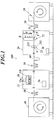
- FIG. 1 shows an example of schematic configuration of a paper processing system 100.
- FIG. 2 is a functional block diagram showing control structure of the paper processing system 100.
- the paper processing system 100 uses continuous paper (roll paper) P as a recording medium, and performs predetermined processes, such as image forming, on the continuous paper P.
- the paper processing system 100 is configured such that a paper feeding apparatus 10, a first image forming apparatus 20, a second image forming apparatus 30 and a winding apparatus 40 are arranged and connected in this order from the upstream side in a conveying direction of the continuous paper P.
- the continuous paper P usable in this embodiment is not particularly limited in its material and so forth, and examples thereof include ordinary paper, paper made of resin as a main material, and converted paper generated by various processes performed on paper.
- Examples of the paper made of resin as a main material include synthetic paper made of polyethylene, polypropylene, polyethylene terephthalate or polyvinyl chloride, and YUPO® paper.
- the paper feeding apparatus 10 is an apparatus that feeds the continuous paper P to the first image forming apparatus 20.
- the continuous paper P which is roll paper
- the continuous paper P wound around the support shaft is conveyed to the outside via a plurality of rollers (e.g. an unwinding roller, a paper feeding roller, etc.) at a constant speed.
- the continuous paper P does not need to be rolled to be held, and may be folded to be held.
- FIG. 1 shows only one continuous paper P, two or more continuous sheets each having a narrow width in a direction orthogonal to the conveying direction may be held side by side.
- the first image forming apparatus 20 is an apparatus that forms images on the continuous paper P by electrophotography.
- the first image forming apparatus 20 is placed on the downstream side of the paper feeding apparatus 10 but on the upstream side of the second image forming apparatus 30 in the conveying direction of the continuous paper P.
- the second image forming apparatus 30 is an apparatus that forms images on the continuous paper P by inkjet technology.
- the second image forming apparatus 30 is placed on the downstream side of the first image forming apparatus 20 but on the upstream side of the winding apparatus 40 in the conveying direction of the continuous paper P.
- the winding apparatus 40 is an apparatus that winds up the continuous paper P conveyed from the second image forming apparatus 30.
- the continuous paper P is wound around and rolled to be held by a support shaft.
- the continuous paper P conveyed from the second image forming apparatus 30 is wound around the support shaft at a constant speed via a plurality of rollers (e.g. a paper receiving roller, a winding roller, etc.).
- the continuous paper P does not need to be rolled to be held, and may be cut page by page (i.e. into sheets).
- the first image forming apparatus 20 and the second image forming apparatus 30 are paper processing apparatuses that perform predetermined processes (first and second image forming processes in this embodiment) on the continuous paper P being conveyed on a conveyance path.
- the first image forming apparatus 20 and the second image forming apparatus 30 have a controller 26 and a controller 36, respectively, and under control of the controller 26 and the controller 36, receive and send various types of information via a communication unit 27 and a communication unit 37, respectively.
- tension applying mechanisms 50 are arranged between the paper feeding apparatus 10 and the first image forming apparatus 20, and between the second image forming apparatus 30 and the winding apparatus 40.
- a buffer mechanism 60 buffer part
- a tension applying mechanism 50 are arranged in this order from the upstream side in the conveying direction of the continuous paper P.
- Each tension applying mechanism 50 includes dancer rollers, and applies a certain level of tension to the continuous paper P.
- the tension applying mechanism 50 may have any configuration as far as it can apply a certain level of tension to the continuous paper P.
- the buffer mechanism 60 temporarily accumulates the continuous paper P.
- the buffer mechanism 60 slackens and retains the continuous paper P, thereby adjusting (timing of) feeding of the continuous paper P to the second image forming apparatus 30. Further, the buffer mechanism 60 absorbs mutual pulling of the continuous paper P by and the slackness of the continuous paper P between the first image forming apparatus 20 and the second image forming apparatus 30 when conveyance of the continuous paper P is stopped, for example.
- the first image forming apparatus 20 is an electrophotographic image forming apparatus, such as a copier.
- the first image forming apparatus 20 includes a paper conveyor 21, an image forming unit 22, a fixing unit 23, an operation display unit 24, a storage 25, the controller 26 and the communication unit 27.
- the paper conveyor 21 includes a conveyance path and a plurality of conveying units arranged on the conveyance path, and conveys the continuous paper P in the first image forming apparatus 20. More specifically, the paper conveyor 21 conveys the continuous paper P conveyed from the paper feeding apparatus 10 to the image forming unit 22, and conveys the continuous paper P having passed through the image forming unit 22 and the fixing unit 23 to the second image forming apparatus 30.
- Each conveying unit is constituted of a pair of rollers that press and contact one another and form a nip part (conveyance nip part) N, and at least one of the rollers is rotationally driven through a drive mechanism that includes an electric motor as a main component, thereby conveying the continuous paper P.
- Each pair of rollers constituting each conveying unit is configured to switch its inter-roller state between a press-and-contact state and a separate state.
- the image forming unit 22 forms toner images by electrophotography, and transfers the toner images to the continuous paper P.
- photoconductive drums (Y, M, C, K) and an intermediate transfer belt B are arranged (shown in FIG. 1 ).
- the intermediate transfer belt B is an endless belt, and wound around and supported by a plurality of rollers to be runnable. Toner images of the respective colors formed on the photoconductive drums (Y, M, C, K) are successively transferred onto the intermediate transfer belt B so as to form, on the intermediate transfer belt B, a toner image (a color image) constituted of layers of the respective colors (Y, M, C, K) superposed on top of one another.
- a bias having a polarity reversed from that of the toners is applied to a transfer roller T that forms a nip part (transfer nip part) N by being arranged to press and contact the intermediate transfer belt B, so that the toner image formed on the intermediate transfer belt B is transferred onto the continuous paper P.
- the transfer roller T is configured to switch its state with the intermediate transfer belt B between the press-and-contact state and the separate state.
- the fixing unit 23 fixes the toner image transferred onto the continuous paper P.
- the fixing unit 23 includes a pair of rollers constituted of a heating roller 231 and a pressurizing roller 232 (shown in FIG. 1 ) to nip the continuous paper P (i.e. hold the continuous paper P between the rollers).
- the heating roller 231 is heated to a predetermined temperature by a heater as a heat source.
- the pressurizing roller 232 is biased to the heating roller 231 by a not-shown elastic member.
- the continuous paper P onto which the toner image has been transferred is given heat and pressure by passing through a nip part (fixing nip part) N constituted of the heating roller 231 and the pressuring roller 232, so that the toner image is fused to the continuous paper P.
- the heating roller 231 and the pressurizing roller 232 are configured to switch their inter-roller state between the press-and-contact state and the separate state.
- a temperature sensor (not shown) is arranged to measure temperature near the outer circumferential surface of the pressurizing roller 232 as temperature of the fixing unit 23.
- the operation display unit 24 includes a display screen, a display that displays various types of information on the display screen, and an operation section that is used by a user to input various instructions.
- the storage 25 is constituted of an HDD (Hard Disk Drive), a nonvolatile semiconductor memory and/or the like.
- the storage 25 stores various programs including system programs and process programs that are executed by the controller 26, data necessary for execution of these programs, and so forth.
- the storage 25 stores various types of setting information necessary to perform the first image forming process and a conveyance control process(es). Further, the storage 25 temporarily stores image data on images to be formed on the continuous paper P.
- the controller 26 controls operations of the components of the first image forming apparatus 20, thereby controlling the whole operation.
- the controller 26 includes a CPU (Central Processing Unit, hardware processor) and a RAM (Random Access Memory).
- the CPU of the controller 26 reads the various programs, such as the system programs and the process programs, stored in the storage 25, to load the read programs to the RAM, and performs various processes in accordance with the loaded programs.
- the controller 26 controls the components of the first image forming apparatus 20 to perform a process for forming images on the continuous paper P (first image forming process).
- controller 26 performs the conveyance control process of, when a conveyance stop signal (conveyance control signal) is output from any of the apparatuses constituting the paper processing system 100, selecting one of first control and second control according to the output timing of the conveyance stop signal, thereby controlling conveyance of the continuous paper P.
- a conveyance stop signal (conveyance control signal)
- This conveyance control process is described below in detail.
- the communication unit 27 includes a serial communication interface, and performs communications with the second image forming apparatus 30, the paper feeding apparatus 10 and the winding apparatus 40 to send and receive information on various processes and so forth.
- the first image forming apparatus 20 may be an MFP (Multi-Function Peripheral) having a copier function, a scanner function, a facsimile function and so forth as well as an image forming function.
- MFP Multi-Function Peripheral
- the second image forming apparatus 30 is an inkjet image forming apparatus, such as an inkjet recording apparatus.
- the second image forming apparatus 30 includes a paper conveyor 31, an image forming unit 32, an ink supply unit 33, an operation display unit 34, a storage 35, the controller 36 and the communication unit 37.
- the paper conveyor 31 includes a conveyance path and a plurality of conveying units arranged on the conveyance path, and conveys the continuous paper P in the second image forming apparatus 30. More specifically, the paper conveyor 31 conveys the continuous paper P conveyed from the first image forming apparatus 20 to the image forming unit 32, and conveys the continuous paper P having passed through the image forming unit 32 to the winding apparatus 40.
- Each conveying unit is constituted of a pair of rollers that press and contact one another and form a nip part, and at least one of the rollers is rotationally driven through a drive mechanism that includes an electric motor as a main component, thereby conveying the continuous paper P.
- Each pair of rollers constituting each conveying unit is configured to switch its inter-roller state between a press-and-contact state and a separate state.
- the image forming unit 32 forms images on the continuous paper P by discharging (ejecting) ink droplets from nozzles of inkjet heads.
- the image forming unit 32 includes a plurality of line heads 32a and a carriage 32b that holds the line heads 32a.
- the line heads 32a discharge inks to the continuous paper P being conveyed by the paper conveyor 31.
- the line heads 32a are provided for respective colors of Y (yellow), M (magenta), C (cyan) and K (black).
- Y yellow
- M magenta
- C cyan
- K black
- the line heads 32a for the colors of Y, M, C, K are arranged in this order from the upstream side in the conveying direction of the continuous paper P.
- the line heads 32a are arranged in the carriage 32b.
- Each line head 32a has a length (width) that covers the whole continuous paper P in a direction (width direction) approximately perpendicular to the conveying direction of the continuous paper P. That is, the second image forming apparatus 30 is a single-pass line-head inkjet recording apparatus.
- Each line head 32a is constituted of a plurality of inkjet heads arranged.
- the carriage 32b may be provided with a carriage heater (not shown) to heat the inks.
- energy-ray curable ink is used as the inks, it is preferable to provide an emitter that emits energy rays to cure the inks after the inks are discharged onto the continuous paper P.
- the emitter is arranged on the downstream side of the line heads 32a in the conveying direction of the continuous paper P, and emits energy rays to the continuous paper P on which an image(s) has been formed, thereby curing the inks discharged onto the continuous paper P.
- the ink supply unit 33 stores the inks and supplies the inks to their respective line heads 32a of the image forming unit 32 so that the inks of the respective colors can be discharged from the nozzles of the line heads 32a.
- Ink usable in this embodiment is not particularly limited.
- the ink include the energy-ray (ultraviolet) curable ink, and ink made of inorganic and organic pigments dispersed in an organic solvent.
- the operation display unit 34 includes a display screen, a display that displays various types of information on the display screen, and an operation section that is used by a user to input various instructions.
- the storage 35 is constituted of an HDD, a nonvolatile semiconductor memory and/or the like.
- the storage 35 stores various programs including system programs and process programs that are executed by the controller 36, data necessary for execution of these programs, and so forth.
- the storage 35 stores various types of setting information necessary to perform the second image forming process.
- the controller 36 controls operations of the components of the second image forming apparatus 30, thereby controlling the whole operation.
- the controller 36 includes a CPU and a RAM.
- the CPU of the controller 36 reads the various programs, such as the system programs and the process programs, stored in the storage 35, to load the read programs to the RAM, and performs various processes in accordance with the loaded programs.
- the controller 36 controls the components of the second image forming apparatus 30 to perform a process for forming images on the continuous paper P (second image forming process).
- controller 36 controls conveyance of the continuous paper P in response to a permission notice sent from the first image forming apparatus 20 that is in execution of the conveyance control process.
- the communication unit 37 includes a serial communication interface, and performs communications with the paper feeding apparatus 10, the first image forming apparatus 20 and the winding apparatus 40 to send and receive information on various processes and so forth.
- the inkjet recording apparatus uses the line heads 32a, but is not limited thereto.
- the inkjet recording apparatus may be a scanning inkjet recording apparatus that forms images by inkjet heads performing scans in a direction orthogonal to the conveying direction of the continuous paper P.
- the inkjet recording apparatus is configured to use the inks of Y (yellow), M (magenta), C (cyan) and K (black), but is not limited thereto.
- the inkjet recording apparatus may be configured to use ink of one color, for example, ink of K (black) only.
- the color of ink to be used is not particularly limited, and hence, other than the above, may be clear (transparent), gold, silver and/or the like, which are called spot color or special color.
- the first image forming apparatus 20 of this embodiment performs the below-described conveyance control process if a conveyance stop signal is output from any of the apparatuses constituting the paper processing system 100 while the first image forming apparatus 20 is in operation.
- the first image forming apparatus 20 selects one of the first control and the second control according to the output timing (received timing) of a conveyance stop signal, thereby controlling (stopping) conveyance of the continuous paper P.
- FIG. 3 is a flowchart showing the conveyance control process.
- Step S101 when the first image forming apparatus 20 is turned on, the controller 26 starts initialization operation (Step S101).
- the controller 26 notifies the second image forming apparatus 30 of prohibition on conveyance of the continuous paper P, and checks operation of each pair of rollers or the like in the first image forming apparatus 20 by causing the rollers or the like to separate from one another (separation operation) and to press and contact one another (press-and-contact operation) as the initialization operation.
- Step S102 determines whether or not the initialization operation has finished.
- Step S102 determines whether or not a conveyance stop signal has been output (received) from the first image forming apparatus 20 or the second image forming apparatus 30 (Step S103).
- Step S103 NO
- the controller 26 When determining that no conveyance stop signal has been output (Step S103: NO), the controller 26 returns to and repeats Step S102 and the following step(s).
- Step S103 when determining that a conveyance stop signal has been output (Step S103: YES), the controller 26 causes the nip parts (the conveyance nip parts, the transfer nip part, the fixing nip part, etc.) N to perform the separation operation (Step S104).
- Step S104 it is preferable that the controller 26 determine whether or not image data on a non-output/non-formed image(s), which has not been output/formed yet, is stored in the storage 25, and when determining that image data on a non-output/non-formed image(s) is stored, the controller 26 causes the nip parts N to perform the separation operation after an image(s) based on the image data is formed.
- the controller 26 causes the nip parts N to perform the separation operation after an image(s) based on the image data is formed.
- Step S105 the controller 26 determines whether or not a predetermined/preset condition to permit a stop of conveyance of the continuous paper P is satisfied.
- the predetermined condition is a condition set for stopping conveyance of the continuous paper P after inside of the first image forming apparatus 20 becomes an appropriate environment.
- the predetermined condition includes at least one of (i) a condition that elapsed time since output of a conveyance stop signal is equal to or larger (longer) than a set value and (ii) a condition that temperature(s) at the nip part(s) N is equal to or smaller (lower) than a set value.
- the set values for the elapsed time and the temperature at the nip parts N can be changed appropriately.
- the set values for the elapse time and/or the temperature at the nip parts N may be changed according to the type of the continuous paper P.
- the set value for the elapsed time may be small (short), and the set value for the temperature at the nip parts N may be large (high).
- the set values for the elapsed time and the temperature at the nip parts N may be changed according to environment, such as temperature and/or humidity, around the first image forming apparatus 20.
- conveyance of the continuous paper P is stopped after the inside of the first image forming apparatus 20 becomes an appropriate environment. This can prevent trouble, for example, prevent the continuous paper P from being damaged by influence of accumulated heat or the like after conveyance of the continuous paper P is stopped.
- Step S105 NO
- the controller 26 repeats Step S105.
- the continuous paper P keeps being conveyed without a stop until the predetermined condition is satisfied.
- Examples of how to keep conveying the continuous paper P include: conveying the continuous paper P in one direction of the conveying direction of the continuous paper P, namely, from the upstream side to the downstream side; and conveying the continuous paper P in both directions of the conveying direction of the continuous paper P alternately from the upstream side to the downstream side and from the downstream side to the upstream side, namely, reciprocating the continuous paper P, every predetermined period of time, which can prevent wasteful blank parts from being generated on the continuous paper P.
- the controller 26 notifies the second image forming apparatus 30 of permission (or instruction if a conveyance stop signal is output from the first image forming apparatus 20) to stop conveying the continuous paper P (i.e. sends a permission notice to the second image forming apparatus 30) (Step S106), and finishes the conveyance control process.
- the controller 36 when receiving the permission notice, performs control to stop conveyance of the continuous paper P.
- Step S102 when determining that the initialization operation has finished (Step S102: YES), the controller 26 determines whether or not an instruction to start image forming (image forming start instruction) has been received (Step S107). When determining that an image forming start instruction has been received (Step S107: YES), the controller 26 starts warm-up operation (Step S108).
- the controller 26 notifies the second image forming apparatus 30 of permission to start conveying the continuous paper P, and starts the warm-up operation when receiving, as the image forming start instruction, an image forming start instruction signal from an external apparatus, an image forming start instruction signal based on a user operation on the operation display unit 24, or the like.
- Step S109 determines whether or not the warm-up operation has finished.
- Step S109: NO determines whether or not a conveyance stop signal has been output from the first image forming apparatus 20 or the second image forming apparatus 30 (Step S110).
- Step S110: NO the controller 26 returns to and repeats Step S109 and the following step(s).
- Step S110 YES
- the controller 26 proceeds to Step S105.
- Step S109 when determining that the warm-up operation has finished (Step S109: YES), the controller 26 starts the first image forming process (Step S111).
- the controller 26 when the warm-up operation finishes, notifies the second image forming apparatus 30 of the conveyance speed of the continuous paper P during image forming, and then starts preparation for image forming.
- the preparation includes: operating an image forming system (e.g. the image forming unit 22); and causing the nip parts N to perform the press-and-contact operation.
- the controller 26 After finishing the preparation for image forming, notifies the second image forming apparatus 30 of the fact that the preparation for image forming has finished, and causes the image forming unit 22 to start image writing, which is included in the image forming.
- Step S112 determines whether or not the image forming has finished.
- Step S112 determines that the image forming has finished.
- Step S112 when determining that the image forming has not finished yet (Step S112: NO), the controller 26 determines whether or not a conveyance stop signal has been output from the first image forming apparatus 20 or the second image forming apparatus 30 (Step S113).
- Step S113 NO
- the controller 26 When determining that no conveyance stop signal has been output (Step S113: NO), the controller 26 returns to and repeats Step S112 and the following step(s).
- Step S113 when determining that a conveyance stop signal has been output (Step S113: YES), the controller 26 proceeds to Step S104.
- the permission notice is sent after the nip parts (the conveyance nip parts, the transfer nip part, the fixing nip part, etc.) N perform the separation operation (first control).
- Step S105 in which the controller 26 determines whether or not the predetermined condition is satisfied. This step may be omitted in terms of productivity.
- Step S104 if image data on a non-output/non-formed image(s) is stored in the storage 25 at the time when a conveyance stop signal is output, the controller 26 causes the nip parts N to perform the separation operation after an image(s) based on the image data is formed.
- the controller 26 may, however, cause the nip parts N to perform the separation operation, regardless of whether or not image data on a non-output/non-formed image(s), which has not been output/formed yet, is present.
- the first image forming apparatus 20 is connected to the second image forming apparatus 30, and performs image forming on the continuous paper P being conveyed on the conveyance path.
- the first image forming apparatus 20 includes the image forming unit 22, the nip part(s) N and the controller 26.
- the image forming unit 22 performs the image forming on the continuous paper P.
- the nip part(s) N nips, on the conveyance path, the continuous paper P.
- a conveyance stop signal (conveyance control signal) is output from the second image forming apparatus 30 or the first image forming apparatus 20, according to the output timing of the conveyance stop signal, the controller 26 selectively performs (i) the first control in which the controller 26 notifies the second image forming apparatus 30 of the permission to stop conveying the continuous paper P after causing the nip part(s) N to perform the separation operation and (ii) the second control in which the controller 26 notifies the second image forming apparatus 30 of the permission without causing the nip part(s) N to perform the separation operation.
- this can prevent trouble due to stops of conveyance of the continuous paper P in the paper processing system 100 in which two or more apparatuses are connected to one another.
- the controller 26 performs the first control if the conveyance stop signal is output during the initialization operation of the first image forming apparatus 20 or during the image forming by the image forming unit 22.
- the controller 26 permits the second image forming apparatus 30 to stop conveying the continuous paper P after causing the rollers or the like constituting each nip part N to separate from one another. This can prevent poor paper conveyance caused by influence of the rollers or the like, which constitute each nip part N, pressing and contacting one another.
- the controller 26 performs the second control if the conveyance stop signal is output during the warm-up operation of the first image forming apparatus 20.
- the controller 26 permits the second image forming apparatus 30 to stop conveying the continuous paper P immediately. This is because the rollers or the like, which constitutes each nip part N, pressing and contacting one another do not affect paper conveyance. The above can stop conveyance of the continuous paper P promptly.
- the controller 26 selects the second control if the first image forming apparatus 20 is in a state in which the rollers or the like, which constitute each nip part N, pressing and contacting one another do not affect paper conveyance. For example, the controller 26 selects the second control if the continuous paper P is being conveyed by/in the second image forming apparatus 30.
- the first image forming apparatus 20 includes the storage 25 that temporarily stores image data, and if image data is stored in the storage 25 at the output timing of the conveyance stop signal, in the first control, the controller 26 causes the nip part(s) N to perform the separation operation after the image forming unit 22 performs the image forming based on the image data.
- conveyance of the continuous paper P is stopped after all images, which have been scheduled by the time of the output of the conveyance stop signal to be formed, are formed on the basis of the image data.
- the controller 26 determines whether or not a predetermined condition is satisfied, and if the controller 26 determines that the predetermined condition is satisfied, notifies the second image forming apparatus 30 of the permission.
- the predetermined condition includes at least one of (i) a condition that elapsed time since the output timing of the conveyance stop signal is equal to or larger than a set value and (ii) a condition that temperature at the nip part(s) N is equal to or smaller than a set value.
- conveyance of the continuous paper P is stopped after the inside of the first image forming apparatus 20 becomes an appropriate environment. This can prevent, for example, the continuous paper P from being damaged by influence of accumulated heat or the like after conveyance of the continuous paper P is stopped.
- the image forming unit 22 performs the image forming by electrophotography.
- the conveyance control process to stop conveyance of the continuous paper P is performed in response to a conveyance stop signal.
- the conveyance control signal includes a conveyance start signal to start conveyance of the continuous paper P. If a conveyance start signal is output as the conveyance control signal, the controller 26 performs, in response to the conveyance start signal, a conveyance control process to start conveyance of the continuous paper P.
- the controller 26 selectively performs (i) first control in which the controller 26 notifies the second image forming apparatus 30 of permission to start conveying the continuous paper P after causing the nip part(s) N to perform the press-and-contact operation and (ii) second control in which the controller 26 notifies the second image forming apparatus 30 of the permission without causing the nip part(s) N to perform the press-and-contact operation.
- controller 26 performs the first control if the conveyance start signal is output, for example, during the initialization operation, and performs the second control if the conveyance start signal is output, for example, during the warm-up operation.
- the second image forming apparatus 30 is an inkjet recording apparatus, but maybe an electrophotographic image forming apparatus like the first image forming apparatus 20.
- the second image forming apparatus 30 may be an apparatus that forms a predetermined pattern(s) made of varnish, leaf/foil or the like on the continuous paper P, or may be an apparatus that performs, on the continuous paper P, a process(es) in addition to or instead of image forming, for example, a post-processing apparatus that performs slitting, die-cutting and/or the like.
- Such an apparatus may be arranged on the upstream side of the first image forming apparatus 20 in the conveying direction of the continuous paper P, if appropriate.
- the paper processing system 100 has two paper processing apparatuses (the first image forming apparatus 20 and the second image forming apparatus 30) connected to one another.
- the number of the paper processing apparatuses to be connected to one another is, however, not limited to two.
- the paper processing system 100 is configured such that the paper processing apparatuses have their respective controllers, and each controller controls its apparatus in response to information (e.g. the permission notice) from another apparatus, but may be configured to have a central controller that controls operation of the paper processing system 100 in whole.
- information e.g. the permission notice
- the central controller outputs commands to perform processes to the controllers (the controller 26 and the controller 36) of the paper processing apparatuses connected to one another, and the controllers control, in response to the commands, operations of their respective apparatuses, which are their respective control targets.
- one of the controllers of the paper processing apparatuses may serve as the central controller.
Landscapes
- Physics & Mathematics (AREA)
- General Physics & Mathematics (AREA)
- Engineering & Computer Science (AREA)
- Microelectronics & Electronic Packaging (AREA)
- Control Or Security For Electrophotography (AREA)
- Paper Feeding For Electrophotography (AREA)
- Handling Of Sheets (AREA)
- Accessory Devices And Overall Control Thereof (AREA)
- Fixing For Electrophotography (AREA)
- Printers Characterized By Their Purpose (AREA)
Abstract
Description
- The present invention relates to an image forming apparatus, a paper processing system and a computer readable storage medium.
- There is known an image forming system in which two or more apparatuses including an electrophotographic image forming apparatus are connected to one another and which performs predetermined processes on continuous paper, such as roll paper. (Refer to
JP 2008-149657 A JP 2015-221532 A JP 2011-194569 A - In this type of image forming system, because the using paper is the continuous paper, if any of the apparatuses needs to stop conveying the continuous paper for replacement of a consumable(s) or the like, all of the apparatuses need to stop conveying the continuous paper.
- However, conveyance distance which the continuous paper is conveyed until the conveyance is stopped after output of a stop signal and/or conveyance distance which the continuous paper is conveyed for restart of the operation differ from apparatus to apparatus, and also differ according to, for example, a state of each apparatus at the time of the output of the stop signal (during warming up, during image forming, etc.). Hence, if the same conveyance control is always performed, the continuous paper is, for example, pulled or slackens, and this causes poor paper conveyance, in particular, in a system in which two or more image forming apparatuses adopting different image forming methods are connected to one another.
- The present invention has been conceived in view of the above problems, and objects of the present invention include preventing trouble caused by starts and/or stops of conveyance of continuous paper in a paper processing system in which two or more apparatuses including an image forming apparatus are connected to one another.
- In order to achieve at least one of the abovementioned objects, according to an aspect of the present invention, there is provided an image forming apparatus that is connected to a paper processing apparatus and performs image forming on continuous paper being conveyed on a conveyance path, including: an image forming unit that performs the image forming on the continuous paper; a nip part that nips, on the conveyance path, the continuous paper; and a hardware processor that, according to an output timing of a conveyance control signal if the conveyance control signal is output from the paper processing apparatus or the image forming apparatus, selectively performs (i) first control in which the hardware processor notifies the paper processing apparatus of permission to start or stop conveying the continuous paper after causing the nip part to perform a press-and-contact operation or a separation operation and (ii) second control in which the hardware processor notifies the paper processing apparatus of the permission without causing the nip part to perform the press-and-contact operation or the separation operation.
- The advantages and features provided by one or more embodiments of the present invention will become more fully understood from the detailed description given hereinbelow and the appended drawings which are given by way of illustration only, and thus are not intended as a definition of the limits of the present invention, wherein:
-
FIG. 1 shows an example of schematic configuration of a paper processing system of the present invention; -
FIG. 2 is a functional block diagram showing control structure of the paper processing system; and -
FIG. 3 is a flowchart showing a conveyance control process of the present invention. - Hereinafter, one or more embodiments of the present invention will be described in detail with reference to the drawings. However, the scope of the present invention is not limited to the disclosed embodiments or the drawings.
- First, configuration of a paper processing system according to an embodiment(s) is described.
-
FIG. 1 shows an example of schematic configuration of apaper processing system 100.FIG. 2 is a functional block diagram showing control structure of thepaper processing system 100. - The
paper processing system 100 uses continuous paper (roll paper) P as a recording medium, and performs predetermined processes, such as image forming, on the continuous paper P. - As shown in
FIG. 1 , thepaper processing system 100 is configured such that apaper feeding apparatus 10, a firstimage forming apparatus 20, a secondimage forming apparatus 30 and awinding apparatus 40 are arranged and connected in this order from the upstream side in a conveying direction of the continuous paper P. - The continuous paper P usable in this embodiment is not particularly limited in its material and so forth, and examples thereof include ordinary paper, paper made of resin as a main material, and converted paper generated by various processes performed on paper. Examples of the paper made of resin as a main material include synthetic paper made of polyethylene, polypropylene, polyethylene terephthalate or polyvinyl chloride, and YUPO® paper.
- The
paper feeding apparatus 10 is an apparatus that feeds the continuous paper P to the firstimage forming apparatus 20. In a casing of thepaper feeding apparatus 10, for example, as shown inFIG. 1 , the continuous paper P, which is roll paper, is wounded around and held by a support shaft to be rotatable. In thepaper feeding apparatus 10, the continuous paper P wound around the support shaft is conveyed to the outside via a plurality of rollers (e.g. an unwinding roller, a paper feeding roller, etc.) at a constant speed. In thepaper feeding apparatus 10, the continuous paper P does not need to be rolled to be held, and may be folded to be held. Further, althoughFIG. 1 shows only one continuous paper P, two or more continuous sheets each having a narrow width in a direction orthogonal to the conveying direction may be held side by side. - The first
image forming apparatus 20 is an apparatus that forms images on the continuous paper P by electrophotography. The firstimage forming apparatus 20 is placed on the downstream side of thepaper feeding apparatus 10 but on the upstream side of the secondimage forming apparatus 30 in the conveying direction of the continuous paper P. - The second
image forming apparatus 30 is an apparatus that forms images on the continuous paper P by inkjet technology. The secondimage forming apparatus 30 is placed on the downstream side of the firstimage forming apparatus 20 but on the upstream side of thewinding apparatus 40 in the conveying direction of the continuous paper P. - The
winding apparatus 40 is an apparatus that winds up the continuous paper P conveyed from the secondimage forming apparatus 30. In a casing of thewinding apparatus 40, for example, as shown inFIG. 1 , the continuous paper P is wound around and rolled to be held by a support shaft. Hence, in thewinding apparatus 40, the continuous paper P conveyed from the secondimage forming apparatus 30 is wound around the support shaft at a constant speed via a plurality of rollers (e.g. a paper receiving roller, a winding roller, etc.). In thewinding apparatus 40, the continuous paper P does not need to be rolled to be held, and may be cut page by page (i.e. into sheets). - In the
paper processing system 100, the firstimage forming apparatus 20 and the secondimage forming apparatus 30 are paper processing apparatuses that perform predetermined processes (first and second image forming processes in this embodiment) on the continuous paper P being conveyed on a conveyance path. - The first
image forming apparatus 20 and the secondimage forming apparatus 30 have acontroller 26 and acontroller 36, respectively, and under control of thecontroller 26 and thecontroller 36, receive and send various types of information via acommunication unit 27 and a communication unit 37, respectively. - Further, in the
paper processing system 100, between thepaper feeding apparatus 10 and the firstimage forming apparatus 20, and between the secondimage forming apparatus 30 and thewinding apparatus 40,tension applying mechanisms 50 are arranged. - Still further, between the first
image forming apparatus 20 and the secondimage forming apparatus 30, a buffer mechanism 60 (buffer part) and atension applying mechanism 50 are arranged in this order from the upstream side in the conveying direction of the continuous paper P. - Each
tension applying mechanism 50 includes dancer rollers, and applies a certain level of tension to the continuous paper P. Thetension applying mechanism 50 may have any configuration as far as it can apply a certain level of tension to the continuous paper P. - The
buffer mechanism 60 temporarily accumulates the continuous paper P. - More specifically, in order to absorb speed difference between conveyance speed of the continuous paper P of the first
image forming apparatus 20 and conveyance speed of the continuous paper P of the secondimage forming apparatus 30, as shown inFIG. 1 , thebuffer mechanism 60 slackens and retains the continuous paper P, thereby adjusting (timing of) feeding of the continuous paper P to the secondimage forming apparatus 30. Further, thebuffer mechanism 60 absorbs mutual pulling of the continuous paper P by and the slackness of the continuous paper P between the firstimage forming apparatus 20 and the secondimage forming apparatus 30 when conveyance of the continuous paper P is stopped, for example. - Next, configuration of the first
image forming apparatus 20 is described in detail. - The first
image forming apparatus 20 is an electrophotographic image forming apparatus, such as a copier. - As shown in
FIG. 2 , the firstimage forming apparatus 20 includes apaper conveyor 21, animage forming unit 22, afixing unit 23, anoperation display unit 24, astorage 25, thecontroller 26 and thecommunication unit 27. - The
paper conveyor 21 includes a conveyance path and a plurality of conveying units arranged on the conveyance path, and conveys the continuous paper P in the firstimage forming apparatus 20. More specifically, thepaper conveyor 21 conveys the continuous paper P conveyed from thepaper feeding apparatus 10 to theimage forming unit 22, and conveys the continuous paper P having passed through theimage forming unit 22 and thefixing unit 23 to the secondimage forming apparatus 30. - Each conveying unit is constituted of a pair of rollers that press and contact one another and form a nip part (conveyance nip part) N, and at least one of the rollers is rotationally driven through a drive mechanism that includes an electric motor as a main component, thereby conveying the continuous paper P. Each pair of rollers constituting each conveying unit is configured to switch its inter-roller state between a press-and-contact state and a separate state.
- The
image forming unit 22 forms toner images by electrophotography, and transfers the toner images to the continuous paper P. - For example, in the
image forming unit 22, photoconductive drums (Y, M, C, K) and an intermediate transfer belt B are arranged (shown inFIG. 1 ). The intermediate transfer belt B is an endless belt, and wound around and supported by a plurality of rollers to be runnable. Toner images of the respective colors formed on the photoconductive drums (Y, M, C, K) are successively transferred onto the intermediate transfer belt B so as to form, on the intermediate transfer belt B, a toner image (a color image) constituted of layers of the respective colors (Y, M, C, K) superposed on top of one another. Then, a bias having a polarity reversed from that of the toners is applied to a transfer roller T that forms a nip part (transfer nip part) N by being arranged to press and contact the intermediate transfer belt B, so that the toner image formed on the intermediate transfer belt B is transferred onto the continuous paper P. The transfer roller T is configured to switch its state with the intermediate transfer belt B between the press-and-contact state and the separate state. - The
fixing unit 23 fixes the toner image transferred onto the continuous paper P. - For example, the fixing
unit 23 includes a pair of rollers constituted of aheating roller 231 and a pressurizing roller 232 (shown inFIG. 1 ) to nip the continuous paper P (i.e. hold the continuous paper P between the rollers). - The
heating roller 231 is heated to a predetermined temperature by a heater as a heat source. - The pressurizing
roller 232 is biased to theheating roller 231 by a not-shown elastic member. The continuous paper P onto which the toner image has been transferred is given heat and pressure by passing through a nip part (fixing nip part) N constituted of theheating roller 231 and the pressuringroller 232, so that the toner image is fused to the continuous paper P. Theheating roller 231 and the pressurizingroller 232 are configured to switch their inter-roller state between the press-and-contact state and the separate state. - Near the outer circumferential surface of the pressurizing
roller 232, a temperature sensor (not shown) is arranged to measure temperature near the outer circumferential surface of the pressurizingroller 232 as temperature of the fixingunit 23. - The
operation display unit 24 includes a display screen, a display that displays various types of information on the display screen, and an operation section that is used by a user to input various instructions. - The
storage 25 is constituted of an HDD (Hard Disk Drive), a nonvolatile semiconductor memory and/or the like. - The
storage 25 stores various programs including system programs and process programs that are executed by thecontroller 26, data necessary for execution of these programs, and so forth. For example, thestorage 25 stores various types of setting information necessary to perform the first image forming process and a conveyance control process(es). Further, thestorage 25 temporarily stores image data on images to be formed on the continuous paper P. - The
controller 26 controls operations of the components of the firstimage forming apparatus 20, thereby controlling the whole operation. - The
controller 26 includes a CPU (Central Processing Unit, hardware processor) and a RAM (Random Access Memory). The CPU of thecontroller 26 reads the various programs, such as the system programs and the process programs, stored in thestorage 25, to load the read programs to the RAM, and performs various processes in accordance with the loaded programs. - For example, the
controller 26 controls the components of the firstimage forming apparatus 20 to perform a process for forming images on the continuous paper P (first image forming process). - Further, the
controller 26 performs the conveyance control process of, when a conveyance stop signal (conveyance control signal) is output from any of the apparatuses constituting thepaper processing system 100, selecting one of first control and second control according to the output timing of the conveyance stop signal, thereby controlling conveyance of the continuous paper P. This conveyance control process is described below in detail. - The
communication unit 27 includes a serial communication interface, and performs communications with the secondimage forming apparatus 30, thepaper feeding apparatus 10 and the windingapparatus 40 to send and receive information on various processes and so forth. - The first
image forming apparatus 20 may be an MFP (Multi-Function Peripheral) having a copier function, a scanner function, a facsimile function and so forth as well as an image forming function. - Next, configuration of the second
image forming apparatus 30 is described in detail. - In this embodiment, the second
image forming apparatus 30 is an inkjet image forming apparatus, such as an inkjet recording apparatus. - As shown in
FIG. 2 , the secondimage forming apparatus 30 includes apaper conveyor 31, animage forming unit 32, anink supply unit 33, anoperation display unit 34, astorage 35, thecontroller 36 and the communication unit 37. - The
paper conveyor 31 includes a conveyance path and a plurality of conveying units arranged on the conveyance path, and conveys the continuous paper P in the secondimage forming apparatus 30. More specifically, thepaper conveyor 31 conveys the continuous paper P conveyed from the firstimage forming apparatus 20 to theimage forming unit 32, and conveys the continuous paper P having passed through theimage forming unit 32 to the windingapparatus 40. - Each conveying unit is constituted of a pair of rollers that press and contact one another and form a nip part, and at least one of the rollers is rotationally driven through a drive mechanism that includes an electric motor as a main component, thereby conveying the continuous paper P. Each pair of rollers constituting each conveying unit is configured to switch its inter-roller state between a press-and-contact state and a separate state.
- The
image forming unit 32 forms images on the continuous paper P by discharging (ejecting) ink droplets from nozzles of inkjet heads. - The
image forming unit 32 includes a plurality of line heads 32a and acarriage 32b that holds the line heads 32a. - The line heads 32a discharge inks to the continuous paper P being conveyed by the
paper conveyor 31. The line heads 32a are provided for respective colors of Y (yellow), M (magenta), C (cyan) and K (black). InFIG. 1 , the line heads 32a for the colors of Y, M, C, K are arranged in this order from the upstream side in the conveying direction of the continuous paper P. - The line heads 32a are arranged in the
carriage 32b. Eachline head 32a has a length (width) that covers the whole continuous paper P in a direction (width direction) approximately perpendicular to the conveying direction of the continuous paper P. That is, the secondimage forming apparatus 30 is a single-pass line-head inkjet recording apparatus. Eachline head 32a is constituted of a plurality of inkjet heads arranged. Thecarriage 32b may be provided with a carriage heater (not shown) to heat the inks. - If energy-ray curable ink is used as the inks, it is preferable to provide an emitter that emits energy rays to cure the inks after the inks are discharged onto the continuous paper P.
- The emitter is arranged on the downstream side of the line heads 32a in the conveying direction of the continuous paper P, and emits energy rays to the continuous paper P on which an image(s) has been formed, thereby curing the inks discharged onto the continuous paper P.
- The
ink supply unit 33 stores the inks and supplies the inks to their respective line heads 32a of theimage forming unit 32 so that the inks of the respective colors can be discharged from the nozzles of the line heads 32a. - Ink usable in this embodiment is not particularly limited. Examples of the ink include the energy-ray (ultraviolet) curable ink, and ink made of inorganic and organic pigments dispersed in an organic solvent.
- The
operation display unit 34 includes a display screen, a display that displays various types of information on the display screen, and an operation section that is used by a user to input various instructions. - The
storage 35 is constituted of an HDD, a nonvolatile semiconductor memory and/or the like. - The
storage 35 stores various programs including system programs and process programs that are executed by thecontroller 36, data necessary for execution of these programs, and so forth. For example, thestorage 35 stores various types of setting information necessary to perform the second image forming process. - The
controller 36 controls operations of the components of the secondimage forming apparatus 30, thereby controlling the whole operation. - The
controller 36 includes a CPU and a RAM. The CPU of thecontroller 36 reads the various programs, such as the system programs and the process programs, stored in thestorage 35, to load the read programs to the RAM, and performs various processes in accordance with the loaded programs. - For example, the
controller 36 controls the components of the secondimage forming apparatus 30 to perform a process for forming images on the continuous paper P (second image forming process). - Further, the
controller 36 controls conveyance of the continuous paper P in response to a permission notice sent from the firstimage forming apparatus 20 that is in execution of the conveyance control process. - The communication unit 37 includes a serial communication interface, and performs communications with the
paper feeding apparatus 10, the firstimage forming apparatus 20 and the windingapparatus 40 to send and receive information on various processes and so forth. - In the above, the inkjet recording apparatus (second image forming apparatus 30) uses the line heads 32a, but is not limited thereto. For example, the inkjet recording apparatus may be a scanning inkjet recording apparatus that forms images by inkjet heads performing scans in a direction orthogonal to the conveying direction of the continuous paper P.
- Further, in the above, the inkjet recording apparatus is configured to use the inks of Y (yellow), M (magenta), C (cyan) and K (black), but is not limited thereto. For example, the inkjet recording apparatus may be configured to use ink of one color, for example, ink of K (black) only.
- Still further, the color of ink to be used is not particularly limited, and hence, other than the above, may be clear (transparent), gold, silver and/or the like, which are called spot color or special color.
- Next, operation of the
paper processing system 100, the firstimage forming apparatus 20 in particular, is described. - The first
image forming apparatus 20 of this embodiment performs the below-described conveyance control process if a conveyance stop signal is output from any of the apparatuses constituting thepaper processing system 100 while the firstimage forming apparatus 20 is in operation. In the conveyance control process, the firstimage forming apparatus 20 selects one of the first control and the second control according to the output timing (received timing) of a conveyance stop signal, thereby controlling (stopping) conveyance of the continuous paper P. -
FIG. 3 is a flowchart showing the conveyance control process. - First, when the first
image forming apparatus 20 is turned on, thecontroller 26 starts initialization operation (Step S101). - More specifically, when the first
image forming apparatus 20 is turned on, thecontroller 26 notifies the secondimage forming apparatus 30 of prohibition on conveyance of the continuous paper P, and checks operation of each pair of rollers or the like in the firstimage forming apparatus 20 by causing the rollers or the like to separate from one another (separation operation) and to press and contact one another (press-and-contact operation) as the initialization operation. - Next, the
controller 26 determines whether or not the initialization operation has finished (Step S102). When determining that the initialization operation has not finished yet (Step S102: NO), thecontroller 26 determines whether or not a conveyance stop signal has been output (received) from the firstimage forming apparatus 20 or the second image forming apparatus 30 (Step S103). - When determining that no conveyance stop signal has been output (Step S103: NO), the
controller 26 returns to and repeats Step S102 and the following step(s). - On the other hand, when determining that a conveyance stop signal has been output (Step S103: YES), the
controller 26 causes the nip parts (the conveyance nip parts, the transfer nip part, the fixing nip part, etc.) N to perform the separation operation (Step S104). - In Step S104, it is preferable that the
controller 26 determine whether or not image data on a non-output/non-formed image(s), which has not been output/formed yet, is stored in thestorage 25, and when determining that image data on a non-output/non-formed image(s) is stored, thecontroller 26 causes the nip parts N to perform the separation operation after an image(s) based on the image data is formed. - That is, if image data is stored in the
storage 25 at the time when a conveyance stop signal is output, thecontroller 26 causes the nip parts N to perform the separation operation after an image(s) based on the image data is formed. - Next, the
controller 26 determines whether or not a predetermined/preset condition to permit a stop of conveyance of the continuous paper P is satisfied (Step S105). - The predetermined condition is a condition set for stopping conveyance of the continuous paper P after inside of the first
image forming apparatus 20 becomes an appropriate environment. For example, the predetermined condition includes at least one of (i) a condition that elapsed time since output of a conveyance stop signal is equal to or larger (longer) than a set value and (ii) a condition that temperature(s) at the nip part(s) N is equal to or smaller (lower) than a set value. - The set values for the elapsed time and the temperature at the nip parts N can be changed appropriately. For example, the set values for the elapse time and/or the temperature at the nip parts N may be changed according to the type of the continuous paper P. For example, if the continuous paper P is made of material having a preset level of heat resistance, the set value for the elapsed time may be small (short), and the set value for the temperature at the nip parts N may be large (high). Further, the set values for the elapsed time and the temperature at the nip parts N may be changed according to environment, such as temperature and/or humidity, around the first
image forming apparatus 20. - In this way, conveyance of the continuous paper P is stopped after the inside of the first
image forming apparatus 20 becomes an appropriate environment. This can prevent trouble, for example, prevent the continuous paper P from being damaged by influence of accumulated heat or the like after conveyance of the continuous paper P is stopped. - When determining that the predetermined condition is not satisfied (Step S105: NO), the
controller 26 repeats Step S105. - In this way, the continuous paper P keeps being conveyed without a stop until the predetermined condition is satisfied.
- Examples of how to keep conveying the continuous paper P include: conveying the continuous paper P in one direction of the conveying direction of the continuous paper P, namely, from the upstream side to the downstream side; and conveying the continuous paper P in both directions of the conveying direction of the continuous paper P alternately from the upstream side to the downstream side and from the downstream side to the upstream side, namely, reciprocating the continuous paper P, every predetermined period of time, which can prevent wasteful blank parts from being generated on the continuous paper P.
- Next, the
controller 26 notifies the secondimage forming apparatus 30 of permission (or instruction if a conveyance stop signal is output from the first image forming apparatus 20) to stop conveying the continuous paper P (i.e. sends a permission notice to the second image forming apparatus 30) (Step S106), and finishes the conveyance control process. - In this way, if a conveyance stop signal is output during the initialization operation, the permission notice is sent after the nip parts N perform the separation operation (first control).
- In the second
image forming apparatus 30, when receiving the permission notice, thecontroller 36 performs control to stop conveyance of the continuous paper P. - In Step S102, when determining that the initialization operation has finished (Step S102: YES), the
controller 26 determines whether or not an instruction to start image forming (image forming start instruction) has been received (Step S107). When determining that an image forming start instruction has been received (Step S107: YES), thecontroller 26 starts warm-up operation (Step S108). - More specifically, when the initialization operation finishes, the
controller 26 notifies the secondimage forming apparatus 30 of permission to start conveying the continuous paper P, and starts the warm-up operation when receiving, as the image forming start instruction, an image forming start instruction signal from an external apparatus, an image forming start instruction signal based on a user operation on theoperation display unit 24, or the like. - As the warm-up operation, conveyance of the continuous paper P near the fixing
unit 23 is started, and the heater of the fixingunit 23 is turned on, for example. - Next, the
controller 26 determines whether or not the warm-up operation has finished (Step S109). When determining that the warm-up operation has not finished yet (Step S109: NO), thecontroller 26 determines whether or not a conveyance stop signal has been output from the firstimage forming apparatus 20 or the second image forming apparatus 30 (Step S110). - When determining that no conveyance stop signal has been output (Step S110: NO), the
controller 26 returns to and repeats Step S109 and the following step(s). - On the other hand, when determining that a conveyance stop signal has been output (Step S110: YES), the
controller 26 proceeds to Step S105. - In this way, if a conveyance stop signal is output during the warm-up operation, the permission notice is sent immediately without the separation operation of the nip parts N (second control).
- In Step S109, when determining that the warm-up operation has finished (Step S109: YES), the
controller 26 starts the first image forming process (Step S111). - More specifically, when the warm-up operation finishes, the
controller 26 notifies the secondimage forming apparatus 30 of the conveyance speed of the continuous paper P during image forming, and then starts preparation for image forming. The preparation includes: operating an image forming system (e.g. the image forming unit 22); and causing the nip parts N to perform the press-and-contact operation. After finishing the preparation for image forming, thecontroller 26 notifies the secondimage forming apparatus 30 of the fact that the preparation for image forming has finished, and causes theimage forming unit 22 to start image writing, which is included in the image forming. - Next, the
controller 26 determines whether or not the image forming has finished (Step S112). When determining that the image forming has finished (Step S112: YES), thecontroller 26 finishes the conveyance control process. - On the other hand, when determining that the image forming has not finished yet (Step S112: NO), the
controller 26 determines whether or not a conveyance stop signal has been output from the firstimage forming apparatus 20 or the second image forming apparatus 30 (Step S113). - When determining that no conveyance stop signal has been output (Step S113: NO), the
controller 26 returns to and repeats Step S112 and the following step(s). - On the other hand, when determining that a conveyance stop signal has been output (Step S113: YES), the
controller 26 proceeds to Step S104. - In this way, if a conveyance stop signal is output during the image forming, the permission notice is sent after the nip parts (the conveyance nip parts, the transfer nip part, the fixing nip part, etc.) N perform the separation operation (first control).
- In order to reduce damage to the continuous paper P, the flowchart shown in
FIG 3 contains Step S105, in which thecontroller 26 determines whether or not the predetermined condition is satisfied. This step may be omitted in terms of productivity. - Further, in Step S104, if image data on a non-output/non-formed image(s) is stored in the
storage 25 at the time when a conveyance stop signal is output, thecontroller 26 causes the nip parts N to perform the separation operation after an image(s) based on the image data is formed. Thecontroller 26 may, however, cause the nip parts N to perform the separation operation, regardless of whether or not image data on a non-output/non-formed image(s), which has not been output/formed yet, is present. - As described above, according to this embodiment, the first
image forming apparatus 20 is connected to the secondimage forming apparatus 30, and performs image forming on the continuous paper P being conveyed on the conveyance path. The firstimage forming apparatus 20 includes theimage forming unit 22, the nip part(s) N and thecontroller 26. Theimage forming unit 22 performs the image forming on the continuous paper P. The nip part(s) N nips, on the conveyance path, the continuous paper P. If a conveyance stop signal (conveyance control signal) is output from the secondimage forming apparatus 30 or the firstimage forming apparatus 20, according to the output timing of the conveyance stop signal, thecontroller 26 selectively performs (i) the first control in which thecontroller 26 notifies the secondimage forming apparatus 30 of the permission to stop conveying the continuous paper P after causing the nip part(s) N to perform the separation operation and (ii) the second control in which thecontroller 26 notifies the secondimage forming apparatus 30 of the permission without causing the nip part(s) N to perform the separation operation. - This can prevent poor paper conveyance caused by the mutual pulling, the slackness or the like of the continuous paper P at the time when conveyance of the continuous paper P is stopped.
- That is, this can prevent trouble due to stops of conveyance of the continuous paper P in the
paper processing system 100 in which two or more apparatuses are connected to one another. - Further, according to this embodiment, the
controller 26 performs the first control if the conveyance stop signal is output during the initialization operation of the firstimage forming apparatus 20 or during the image forming by theimage forming unit 22. - In this way, during the initialization operation of the first
image forming apparatus 20 or the image forming by theimage forming unit 22, thecontroller 26 permits the secondimage forming apparatus 30 to stop conveying the continuous paper P after causing the rollers or the like constituting each nip part N to separate from one another. This can prevent poor paper conveyance caused by influence of the rollers or the like, which constitute each nip part N, pressing and contacting one another. - Further, according to this embodiment, the
controller 26 performs the second control if the conveyance stop signal is output during the warm-up operation of the firstimage forming apparatus 20. - In this way, if the conveyance stop signal is output during the warm-up operation of the first
image forming apparatus 20, thecontroller 26 permits the secondimage forming apparatus 30 to stop conveying the continuous paper P immediately. This is because the rollers or the like, which constitutes each nip part N, pressing and contacting one another do not affect paper conveyance. The above can stop conveyance of the continuous paper P promptly. - Other than during the warm-up operation of the first
image forming apparatus 20, thecontroller 26 selects the second control if the firstimage forming apparatus 20 is in a state in which the rollers or the like, which constitute each nip part N, pressing and contacting one another do not affect paper conveyance. For example, thecontroller 26 selects the second control if the continuous paper P is being conveyed by/in the secondimage forming apparatus 30. - Further, according to this embodiment, the first
image forming apparatus 20 includes thestorage 25 that temporarily stores image data, and if image data is stored in thestorage 25 at the output timing of the conveyance stop signal, in the first control, thecontroller 26 causes the nip part(s) N to perform the separation operation after theimage forming unit 22 performs the image forming based on the image data. - In this way, conveyance of the continuous paper P is stopped after all images, which have been scheduled by the time of the output of the conveyance stop signal to be formed, are formed on the basis of the image data.
- Further, according to this embodiment, in the first control and the second control, before notifying the second
image forming apparatus 30 of the permission, thecontroller 26 determines whether or not a predetermined condition is satisfied, and if thecontroller 26 determines that the predetermined condition is satisfied, notifies the secondimage forming apparatus 30 of the permission. - The predetermined condition includes at least one of (i) a condition that elapsed time since the output timing of the conveyance stop signal is equal to or larger than a set value and (ii) a condition that temperature at the nip part(s) N is equal to or smaller than a set value.
- In this way, conveyance of the continuous paper P is stopped after the inside of the first
image forming apparatus 20 becomes an appropriate environment. This can prevent, for example, the continuous paper P from being damaged by influence of accumulated heat or the like after conveyance of the continuous paper P is stopped. - Further, according to this embodiment, the
image forming unit 22 performs the image forming by electrophotography. - This can prevent trouble due to stops of conveyance of the continuous paper P in the
paper processing system 100 which includes the firstimage forming apparatus 20 that forms images by electrophotography. - In the above embodiment, the conveyance control process to stop conveyance of the continuous paper P is performed in response to a conveyance stop signal. The conveyance control signal, however, includes a conveyance start signal to start conveyance of the continuous paper P. If a conveyance start signal is output as the conveyance control signal, the
controller 26 performs, in response to the conveyance start signal, a conveyance control process to start conveyance of the continuous paper P. - More specifically, if a conveyance start signal is output, according to the output timing of the conveyance start signal, the
controller 26 selectively performs (i) first control in which thecontroller 26 notifies the secondimage forming apparatus 30 of permission to start conveying the continuous paper P after causing the nip part(s) N to perform the press-and-contact operation and (ii) second control in which thecontroller 26 notifies the secondimage forming apparatus 30 of the permission without causing the nip part(s) N to perform the press-and-contact operation. - This can prevent trouble due to starts of conveyance of the continuous paper P in the
paper processing system 100 in which two or more apparatuses are connected to one another. - Further, the
controller 26 performs the first control if the conveyance start signal is output, for example, during the initialization operation, and performs the second control if the conveyance start signal is output, for example, during the warm-up operation. - Further, in the above embodiment, the second
image forming apparatus 30 is an inkjet recording apparatus, but maybe an electrophotographic image forming apparatus like the firstimage forming apparatus 20. - The second
image forming apparatus 30 may be an apparatus that forms a predetermined pattern(s) made of varnish, leaf/foil or the like on the continuous paper P, or may be an apparatus that performs, on the continuous paper P, a process(es) in addition to or instead of image forming, for example, a post-processing apparatus that performs slitting, die-cutting and/or the like. - Such an apparatus may be arranged on the upstream side of the first
image forming apparatus 20 in the conveying direction of the continuous paper P, if appropriate. - Further, in the above embodiment, the
paper processing system 100 has two paper processing apparatuses (the firstimage forming apparatus 20 and the second image forming apparatus 30) connected to one another. The number of the paper processing apparatuses to be connected to one another is, however, not limited to two. - Further, in the above embodiment, as shown in
FIG. 2 , thepaper processing system 100 is configured such that the paper processing apparatuses have their respective controllers, and each controller controls its apparatus in response to information (e.g. the permission notice) from another apparatus, but may be configured to have a central controller that controls operation of thepaper processing system 100 in whole. - In this case, the central controller outputs commands to perform processes to the controllers (the
controller 26 and the controller 36) of the paper processing apparatuses connected to one another, and the controllers control, in response to the commands, operations of their respective apparatuses, which are their respective control targets. - Alternatively, one of the controllers of the paper processing apparatuses may serve as the central controller.
- Further, in the
paper processing system 100, if a conveyance stop signal due to occurrence of abnormality that puts a user in danger or breaks down the apparatus(es) is output, conveyance of the continuous paper P is stopped immediately, regardless of its output timing. - Although one or more embodiments of the present invention have been described and illustrated in detail, the disclosed embodiment(s) are made for purposes of illustration and example only and not limitation. The scope of the present invention should be interpreted by terms of the appended claims.
Claims (10)
- An image forming apparatus (20) that is connected to a paper processing apparatus (30) and performs image forming on continuous paper (P) being conveyed on a conveyance path, comprising:an image forming unit (22) that performs the image forming on the continuous paper (P);a nip part (N) that nips, on the conveyance path, the continuous paper (P); anda hardware processor (26) that, according to an output timing of a conveyance control signal if the conveyance control signal is output from the paper processing apparatus (30) or the image forming apparatus (20), selectively performs (i) first control in which the hardware processor (26) notifies the paper processing apparatus (30) of permission to start or stop conveying the continuous paper (P) after causing the nip part (N) to perform a press-and-contact operation or a separation operation and (ii) second control in which the hardware processor (26) notifies the paper processing apparatus (30) of the permission without causing the nip part (N) to perform the press-and-contact operation or the separation operation.
- The image forming apparatus (20) according to claim 1, wherein the hardware processor (26) performs the first control if the conveyance control signal is output during an initialization operation of the image forming apparatus (20) or during the image forming by the image forming unit (22).
- The image forming apparatus (20) according to claim 1 or 2, wherein the hardware processor (26) performs the second control if the conveyance control signal is output during an warm-up operation of the image forming apparatus (20).
- The image forming apparatus (20) according to any one of claims 1 to 3, comprising a storage (25) that temporarily stores image data, wherein
if the image data is stored in the storage (25) at the output timing of the conveyance control signal, in the first control, the hardware processor (26) causes the nip part (N) to perform the separation operation after the image forming unit (22) performs the image forming based on the image data. - The image forming apparatus (20) according to any one of claims 1 to 4, wherein in the first control and the second control, before notifying the paper processing apparatus (30) of the permission, the hardware processor (26) determines whether or not a predetermined condition is satisfied, and if the hardware processor (26) determines that the predetermined condition is satisfied, notifies the paper processing apparatus (30) of the permission.
- The image forming apparatus (20) according to claim 5, wherein the predetermined condition includes at least one of (i) a condition that elapsed time since the output timing of the conveyance control signal is equal to or larger than a set value and (ii) a condition that a temperature at the nip part (N) is equal to or smaller than a set value.
- The image forming apparatus (20) according to any one of claims 1 to 6, wherein the image forming unit (22) performs the image forming by electrophotography.
- A paper processing system (100) that performs a predetermined process on continuous paper (P) being conveyed on a conveyance path, comprising:a plurality of paper processing apparatuses (20, 30) connected to one another, whereinat least one of the paper processing apparatuses (20, 30) is the image forming apparatus (20) according to any one of claims 1 to 7.
- The paper processing system (100) according to claim 8, comprising a buffer part (60) between the paper processing apparatuses (20, 30), the buffer part (60) temporarily accumulating the continuous paper (P).
- A non-transitory computer readable storage medium (25) storing a program causing a computer (26) of an image forming apparatus (20) connected to a paper processing apparatus (30), the image forming apparatus (20) including an image forming unit (22) that performs image forming on continuous paper (P) being conveyed on a conveyance path, and a nip part (N) that nips, on the conveyance path, the continuous paper (P), to perform:according to an output timing of a conveyance control signal if the conveyance control signal is output from the paper processing apparatus (30) or the image forming apparatus (20), selectively performing (i) first control in which the computer (26) notifies the paper processing apparatus (30) of permission to start or stop conveying the continuous paper (P) after causing the nip part (N) to perform a press-and-contact operation or a separation operation and (ii) second control in which the computer (26) notifies the paper processing apparatus (30) of the permission without causing the nip part (N) to perform the press-and-contact operation or the separation operation.
Applications Claiming Priority (1)
| Application Number | Priority Date | Filing Date | Title |
|---|---|---|---|
| JP2017169954A JP7009847B2 (en) | 2017-09-05 | 2017-09-05 | Image forming equipment, paper processing system and program |
Publications (2)
| Publication Number | Publication Date |
|---|---|
| EP3451068A1 true EP3451068A1 (en) | 2019-03-06 |
| EP3451068B1 EP3451068B1 (en) | 2021-07-28 |
Family
ID=63294160
Family Applications (1)
| Application Number | Title | Priority Date | Filing Date |
|---|---|---|---|
| EP18189514.5A Active EP3451068B1 (en) | 2017-09-05 | 2018-08-17 | Image forming apparatus, paper processing system and computer readable storage medium |
Country Status (4)
| Country | Link |
|---|---|
| US (1) | US20190070871A1 (en) |
| EP (1) | EP3451068B1 (en) |
| JP (1) | JP7009847B2 (en) |
| CN (1) | CN109426114B (en) |
Families Citing this family (2)
| Publication number | Priority date | Publication date | Assignee | Title |
|---|---|---|---|---|
| JP7283181B2 (en) * | 2019-04-01 | 2023-05-30 | 富士フイルムビジネスイノベーション株式会社 | Image forming apparatus and control program |
| JP7800257B2 (en) * | 2022-03-30 | 2026-01-16 | セイコーエプソン株式会社 | Recording Systems and Post-Processing Devices |
Citations (6)
| Publication number | Priority date | Publication date | Assignee | Title |
|---|---|---|---|---|
| JP2008149657A (en) | 2006-12-20 | 2008-07-03 | Fuji Xerox Co Ltd | Continuous form printing system |
| US20110228294A1 (en) * | 2010-03-17 | 2011-09-22 | Fuji Xerox Co., Ltd. | Image formation apparatus, image formation system, and computer readable medium |
| US20140064747A1 (en) * | 2012-09-05 | 2014-03-06 | Casio Computer Co., Ltd. | Printing apparatus, printing method, and storage medium |
| US20150078771A1 (en) * | 2013-09-13 | 2015-03-19 | Konica Minolta, Inc. | Image forming apparatus, image forming system, image forming method, and non-transitory computer readable recording medium stored with image forming program |
| JP2015221532A (en) | 2014-05-23 | 2015-12-10 | 富士ゼロックス株式会社 | Image forming apparatus, cutting processing apparatus, printing system, and program |
| EP3144736A1 (en) * | 2015-09-10 | 2017-03-22 | Oki Data Corporation | Image forming apparatus |
Family Cites Families (15)
| Publication number | Priority date | Publication date | Assignee | Title |
|---|---|---|---|---|
| JP3517859B2 (en) * | 1996-03-14 | 2004-04-12 | セイコーエプソン株式会社 | Printing apparatus and control method of printing apparatus |
| JPH07146625A (en) * | 1993-11-13 | 1995-06-06 | Asahi Optical Co Ltd | Printer that uses continuous paper |
| EP1403201B1 (en) * | 2002-09-27 | 2007-01-24 | Eastman Kodak Company | Pre-registration speed and timing adjust system |
| JP5127311B2 (en) * | 2007-06-11 | 2013-01-23 | キヤノン株式会社 | Image forming apparatus, image forming apparatus control method, and program |
| DE102007034246B4 (en) * | 2007-07-23 | 2010-10-28 | OCé PRINTING SYSTEMS GMBH | Device with a Vorzentriervorrichtung and a buffer device for the supply of a printing material web to a printing device |
| JP5151527B2 (en) * | 2008-02-14 | 2013-02-27 | セイコーエプソン株式会社 | Roll paper printer and printing control method for roll paper printer |
| JP2009269736A (en) * | 2008-05-09 | 2009-11-19 | Ricoh Co Ltd | Image forming device |
| JP5278261B2 (en) * | 2009-09-14 | 2013-09-04 | 富士ゼロックス株式会社 | Image forming system and image forming apparatus |
| JP5546288B2 (en) * | 2010-02-26 | 2014-07-09 | キヤノン株式会社 | Sheet thickness detection apparatus, image forming apparatus, and sheet feeding apparatus |
| JP5958401B2 (en) * | 2013-03-28 | 2016-08-02 | コニカミノルタ株式会社 | Image forming system and intermediate apparatus |
| JP6044618B2 (en) * | 2014-11-04 | 2016-12-14 | コニカミノルタ株式会社 | Image forming apparatus and image forming method |
| JP6464759B2 (en) * | 2015-01-15 | 2019-02-06 | コニカミノルタ株式会社 | Image forming apparatus |
| JP6455351B2 (en) * | 2015-07-16 | 2019-01-23 | 富士ゼロックス株式会社 | Image forming apparatus |
| JP6248995B2 (en) * | 2015-09-02 | 2017-12-20 | コニカミノルタ株式会社 | Image forming system |
| US10564582B2 (en) * | 2016-06-20 | 2020-02-18 | Ricoh Company, Ltd. | Rotating member control device, conveying device, and image forming apparatus |
-
2017
- 2017-09-05 JP JP2017169954A patent/JP7009847B2/en active Active
-
2018
- 2018-08-17 EP EP18189514.5A patent/EP3451068B1/en active Active
- 2018-08-29 US US16/116,100 patent/US20190070871A1/en not_active Abandoned
- 2018-09-04 CN CN201811025327.9A patent/CN109426114B/en active Active
Patent Citations (7)
| Publication number | Priority date | Publication date | Assignee | Title |
|---|---|---|---|---|
| JP2008149657A (en) | 2006-12-20 | 2008-07-03 | Fuji Xerox Co Ltd | Continuous form printing system |
| US20110228294A1 (en) * | 2010-03-17 | 2011-09-22 | Fuji Xerox Co., Ltd. | Image formation apparatus, image formation system, and computer readable medium |
| JP2011194569A (en) | 2010-03-17 | 2011-10-06 | Fuji Xerox Co Ltd | Image formation apparatus, image formation system, and image formation program |
| US20140064747A1 (en) * | 2012-09-05 | 2014-03-06 | Casio Computer Co., Ltd. | Printing apparatus, printing method, and storage medium |
| US20150078771A1 (en) * | 2013-09-13 | 2015-03-19 | Konica Minolta, Inc. | Image forming apparatus, image forming system, image forming method, and non-transitory computer readable recording medium stored with image forming program |
| JP2015221532A (en) | 2014-05-23 | 2015-12-10 | 富士ゼロックス株式会社 | Image forming apparatus, cutting processing apparatus, printing system, and program |
| EP3144736A1 (en) * | 2015-09-10 | 2017-03-22 | Oki Data Corporation | Image forming apparatus |
Also Published As
| Publication number | Publication date |
|---|---|
| JP7009847B2 (en) | 2022-01-26 |
| US20190070871A1 (en) | 2019-03-07 |
| CN109426114B (en) | 2024-05-17 |
| JP2019045738A (en) | 2019-03-22 |
| EP3451068B1 (en) | 2021-07-28 |
| CN109426114A (en) | 2019-03-05 |
Similar Documents
| Publication | Publication Date | Title |
|---|---|---|
| JP5971799B2 (en) | Printing apparatus, printing method, and program | |
| US8382227B2 (en) | Printing apparatus for detecting and avoiding unprintable regions on recording mediums | |
| US20110211890A1 (en) | Printing apparatus and decurling device | |
| EP3451068B1 (en) | Image forming apparatus, paper processing system and computer readable storage medium | |
| US10248061B2 (en) | Image forming apparatus configured to form an image on continuous paper with a blank between jobs | |
| EP3179311B1 (en) | Image forming apparatus, image forming system and recording medium | |
| JP6736933B2 (en) | Image forming device | |
| US12436487B2 (en) | Image forming system | |
| US12222667B2 (en) | Image forming system | |
| US9715196B2 (en) | Method of controlling image forming apparatus, image forming apparatus and image forming system to identify paper position and paper deformation | |
| JP2014134668A (en) | Image forming apparatus | |
| US9110419B2 (en) | Image forming system and image forming apparatus | |
| US9952538B2 (en) | Image forming apparatus which controls the transfer of toner to a heating member | |
| JP6907682B2 (en) | Image formation system and control method of image formation system | |
| JP6412693B2 (en) | Fixing apparatus, image forming apparatus, and image forming method | |
| JP7468099B2 (en) | Image forming control device and image forming apparatus | |
| JP2015051816A (en) | Printing apparatus, recording medium supply apparatus, skew correction method for recording medium, and program | |
| US11815850B2 (en) | Image forming system | |
| US20250123782A1 (en) | Printing apparatus, method of controlling printing apparatus, and storage medium | |
| US20110244380A1 (en) | Image forming apparatus and image forming method | |
| JP6524804B2 (en) | Image forming device | |
| US10353336B2 (en) | Image forming apparatus | |
| JP5883524B2 (en) | Image processing apparatus and image forming apparatus | |
| JP6264174B2 (en) | Image forming apparatus and image forming apparatus control method | |
| JP7089341B2 (en) | Image recording device |
Legal Events
| Date | Code | Title | Description |
|---|---|---|---|
| PUAI | Public reference made under article 153(3) epc to a published international application that has entered the european phase |
Free format text: ORIGINAL CODE: 0009012 |
|
| STAA | Information on the status of an ep patent application or granted ep patent |
Free format text: STATUS: THE APPLICATION HAS BEEN PUBLISHED |
|
| AK | Designated contracting states |
Kind code of ref document: A1 Designated state(s): AL AT BE BG CH CY CZ DE DK EE ES FI FR GB GR HR HU IE IS IT LI LT LU LV MC MK MT NL NO PL PT RO RS SE SI SK SM TR |
|
| AX | Request for extension of the european patent |
Extension state: BA ME |
|
| STAA | Information on the status of an ep patent application or granted ep patent |
Free format text: STATUS: REQUEST FOR EXAMINATION WAS MADE |
|
| 17P | Request for examination filed |
Effective date: 20190712 |
|
| RBV | Designated contracting states (corrected) |
Designated state(s): AL AT BE BG CH CY CZ DE DK EE ES FI FR GB GR HR HU IE IS IT LI LT LU LV MC MK MT NL NO PL PT RO RS SE SI SK SM TR |
|
| GRAP | Despatch of communication of intention to grant a patent |
Free format text: ORIGINAL CODE: EPIDOSNIGR1 |
|
| STAA | Information on the status of an ep patent application or granted ep patent |
Free format text: STATUS: GRANT OF PATENT IS INTENDED |
|
| INTG | Intention to grant announced |
Effective date: 20210507 |
|
| GRAS | Grant fee paid |
Free format text: ORIGINAL CODE: EPIDOSNIGR3 |
|
| GRAA | (expected) grant |
Free format text: ORIGINAL CODE: 0009210 |
|
| STAA | Information on the status of an ep patent application or granted ep patent |
Free format text: STATUS: THE PATENT HAS BEEN GRANTED |
|
| AK | Designated contracting states |
Kind code of ref document: B1 Designated state(s): AL AT BE BG CH CY CZ DE DK EE ES FI FR GB GR HR HU IE IS IT LI LT LU LV MC MK MT NL NO PL PT RO RS SE SI SK SM TR |
|
| REG | Reference to a national code |
Ref country code: GB Ref legal event code: FG4D |
|
| REG | Reference to a national code |
Ref country code: CH Ref legal event code: EP |
|
| REG | Reference to a national code |
Ref country code: AT Ref legal event code: REF Ref document number: 1415240 Country of ref document: AT Kind code of ref document: T Effective date: 20210815 |
|
| REG | Reference to a national code |
Ref country code: IE Ref legal event code: FG4D |
|
| REG | Reference to a national code |
Ref country code: DE Ref legal event code: R096 Ref document number: 602018020690 Country of ref document: DE |
|
| REG | Reference to a national code |
Ref country code: LT Ref legal event code: MG9D |
|
| REG | Reference to a national code |
Ref country code: NL Ref legal event code: MP Effective date: 20210728 |
|
| REG | Reference to a national code |
Ref country code: AT Ref legal event code: MK05 Ref document number: 1415240 Country of ref document: AT Kind code of ref document: T Effective date: 20210728 |
|
| PG25 | Lapsed in a contracting state [announced via postgrant information from national office to epo] |
Ref country code: RS Free format text: LAPSE BECAUSE OF FAILURE TO SUBMIT A TRANSLATION OF THE DESCRIPTION OR TO PAY THE FEE WITHIN THE PRESCRIBED TIME-LIMIT Effective date: 20210728 Ref country code: SE Free format text: LAPSE BECAUSE OF FAILURE TO SUBMIT A TRANSLATION OF THE DESCRIPTION OR TO PAY THE FEE WITHIN THE PRESCRIBED TIME-LIMIT Effective date: 20210728 Ref country code: HR Free format text: LAPSE BECAUSE OF FAILURE TO SUBMIT A TRANSLATION OF THE DESCRIPTION OR TO PAY THE FEE WITHIN THE PRESCRIBED TIME-LIMIT Effective date: 20210728 Ref country code: FI Free format text: LAPSE BECAUSE OF FAILURE TO SUBMIT A TRANSLATION OF THE DESCRIPTION OR TO PAY THE FEE WITHIN THE PRESCRIBED TIME-LIMIT Effective date: 20210728 Ref country code: ES Free format text: LAPSE BECAUSE OF FAILURE TO SUBMIT A TRANSLATION OF THE DESCRIPTION OR TO PAY THE FEE WITHIN THE PRESCRIBED TIME-LIMIT Effective date: 20210728 Ref country code: BG Free format text: LAPSE BECAUSE OF FAILURE TO SUBMIT A TRANSLATION OF THE DESCRIPTION OR TO PAY THE FEE WITHIN THE PRESCRIBED TIME-LIMIT Effective date: 20211028 Ref country code: AT Free format text: LAPSE BECAUSE OF FAILURE TO SUBMIT A TRANSLATION OF THE DESCRIPTION OR TO PAY THE FEE WITHIN THE PRESCRIBED TIME-LIMIT Effective date: 20210728 Ref country code: LT Free format text: LAPSE BECAUSE OF FAILURE TO SUBMIT A TRANSLATION OF THE DESCRIPTION OR TO PAY THE FEE WITHIN THE PRESCRIBED TIME-LIMIT Effective date: 20210728 Ref country code: NO Free format text: LAPSE BECAUSE OF FAILURE TO SUBMIT A TRANSLATION OF THE DESCRIPTION OR TO PAY THE FEE WITHIN THE PRESCRIBED TIME-LIMIT Effective date: 20211028 Ref country code: NL Free format text: LAPSE BECAUSE OF FAILURE TO SUBMIT A TRANSLATION OF THE DESCRIPTION OR TO PAY THE FEE WITHIN THE PRESCRIBED TIME-LIMIT Effective date: 20210728 Ref country code: PT Free format text: LAPSE BECAUSE OF FAILURE TO SUBMIT A TRANSLATION OF THE DESCRIPTION OR TO PAY THE FEE WITHIN THE PRESCRIBED TIME-LIMIT Effective date: 20211129 |
|
| PG25 | Lapsed in a contracting state [announced via postgrant information from national office to epo] |
Ref country code: PL Free format text: LAPSE BECAUSE OF FAILURE TO SUBMIT A TRANSLATION OF THE DESCRIPTION OR TO PAY THE FEE WITHIN THE PRESCRIBED TIME-LIMIT Effective date: 20210728 Ref country code: LV Free format text: LAPSE BECAUSE OF FAILURE TO SUBMIT A TRANSLATION OF THE DESCRIPTION OR TO PAY THE FEE WITHIN THE PRESCRIBED TIME-LIMIT Effective date: 20210728 Ref country code: GR Free format text: LAPSE BECAUSE OF FAILURE TO SUBMIT A TRANSLATION OF THE DESCRIPTION OR TO PAY THE FEE WITHIN THE PRESCRIBED TIME-LIMIT Effective date: 20211029 |
|
| REG | Reference to a national code |
Ref country code: CH Ref legal event code: PL |
|
| REG | Reference to a national code |
Ref country code: BE Ref legal event code: MM Effective date: 20210831 |
|
| PG25 | Lapsed in a contracting state [announced via postgrant information from national office to epo] |
Ref country code: LI Free format text: LAPSE BECAUSE OF NON-PAYMENT OF DUE FEES Effective date: 20210831 Ref country code: DK Free format text: LAPSE BECAUSE OF FAILURE TO SUBMIT A TRANSLATION OF THE DESCRIPTION OR TO PAY THE FEE WITHIN THE PRESCRIBED TIME-LIMIT Effective date: 20210728 Ref country code: CH Free format text: LAPSE BECAUSE OF NON-PAYMENT OF DUE FEES Effective date: 20210831 |
|
| REG | Reference to a national code |
Ref country code: DE Ref legal event code: R097 Ref document number: 602018020690 Country of ref document: DE |
|
| PG25 | Lapsed in a contracting state [announced via postgrant information from national office to epo] |
Ref country code: SM Free format text: LAPSE BECAUSE OF FAILURE TO SUBMIT A TRANSLATION OF THE DESCRIPTION OR TO PAY THE FEE WITHIN THE PRESCRIBED TIME-LIMIT Effective date: 20210728 Ref country code: SK Free format text: LAPSE BECAUSE OF FAILURE TO SUBMIT A TRANSLATION OF THE DESCRIPTION OR TO PAY THE FEE WITHIN THE PRESCRIBED TIME-LIMIT Effective date: 20210728 Ref country code: RO Free format text: LAPSE BECAUSE OF FAILURE TO SUBMIT A TRANSLATION OF THE DESCRIPTION OR TO PAY THE FEE WITHIN THE PRESCRIBED TIME-LIMIT Effective date: 20210728 Ref country code: MC Free format text: LAPSE BECAUSE OF FAILURE TO SUBMIT A TRANSLATION OF THE DESCRIPTION OR TO PAY THE FEE WITHIN THE PRESCRIBED TIME-LIMIT Effective date: 20210728 Ref country code: LU Free format text: LAPSE BECAUSE OF NON-PAYMENT OF DUE FEES Effective date: 20210817 Ref country code: EE Free format text: LAPSE BECAUSE OF FAILURE TO SUBMIT A TRANSLATION OF THE DESCRIPTION OR TO PAY THE FEE WITHIN THE PRESCRIBED TIME-LIMIT Effective date: 20210728 Ref country code: CZ Free format text: LAPSE BECAUSE OF FAILURE TO SUBMIT A TRANSLATION OF THE DESCRIPTION OR TO PAY THE FEE WITHIN THE PRESCRIBED TIME-LIMIT Effective date: 20210728 Ref country code: AL Free format text: LAPSE BECAUSE OF FAILURE TO SUBMIT A TRANSLATION OF THE DESCRIPTION OR TO PAY THE FEE WITHIN THE PRESCRIBED TIME-LIMIT Effective date: 20210728 |
|
| PLBE | No opposition filed within time limit |
Free format text: ORIGINAL CODE: 0009261 |
|
| STAA | Information on the status of an ep patent application or granted ep patent |
Free format text: STATUS: NO OPPOSITION FILED WITHIN TIME LIMIT |
|
| 26N | No opposition filed |
Effective date: 20220429 |
|
| PG25 | Lapsed in a contracting state [announced via postgrant information from national office to epo] |
Ref country code: IT Free format text: LAPSE BECAUSE OF FAILURE TO SUBMIT A TRANSLATION OF THE DESCRIPTION OR TO PAY THE FEE WITHIN THE PRESCRIBED TIME-LIMIT Effective date: 20210728 Ref country code: IE Free format text: LAPSE BECAUSE OF NON-PAYMENT OF DUE FEES Effective date: 20210817 Ref country code: BE Free format text: LAPSE BECAUSE OF NON-PAYMENT OF DUE FEES Effective date: 20210831 |
|
| P01 | Opt-out of the competence of the unified patent court (upc) registered |
Effective date: 20230510 |
|
| PG25 | Lapsed in a contracting state [announced via postgrant information from national office to epo] |
Ref country code: CY Free format text: LAPSE BECAUSE OF FAILURE TO SUBMIT A TRANSLATION OF THE DESCRIPTION OR TO PAY THE FEE WITHIN THE PRESCRIBED TIME-LIMIT Effective date: 20210728 |
|
| PG25 | Lapsed in a contracting state [announced via postgrant information from national office to epo] |
Ref country code: HU Free format text: LAPSE BECAUSE OF FAILURE TO SUBMIT A TRANSLATION OF THE DESCRIPTION OR TO PAY THE FEE WITHIN THE PRESCRIBED TIME-LIMIT; INVALID AB INITIO Effective date: 20180817 |
|
| PG25 | Lapsed in a contracting state [announced via postgrant information from national office to epo] |
Ref country code: MK Free format text: LAPSE BECAUSE OF FAILURE TO SUBMIT A TRANSLATION OF THE DESCRIPTION OR TO PAY THE FEE WITHIN THE PRESCRIBED TIME-LIMIT Effective date: 20210728 |
|
| PG25 | Lapsed in a contracting state [announced via postgrant information from national office to epo] |
Ref country code: TR Free format text: LAPSE BECAUSE OF FAILURE TO SUBMIT A TRANSLATION OF THE DESCRIPTION OR TO PAY THE FEE WITHIN THE PRESCRIBED TIME-LIMIT Effective date: 20210728 |
|
| PGFP | Annual fee paid to national office [announced via postgrant information from national office to epo] |
Ref country code: GB Payment date: 20240627 Year of fee payment: 7 |
|
| PG25 | Lapsed in a contracting state [announced via postgrant information from national office to epo] |
Ref country code: MT Free format text: LAPSE BECAUSE OF FAILURE TO SUBMIT A TRANSLATION OF THE DESCRIPTION OR TO PAY THE FEE WITHIN THE PRESCRIBED TIME-LIMIT Effective date: 20210728 |
|
| PGFP | Annual fee paid to national office [announced via postgrant information from national office to epo] |
Ref country code: FR Payment date: 20250610 Year of fee payment: 8 |
|
| PGFP | Annual fee paid to national office [announced via postgrant information from national office to epo] |
Ref country code: DE Payment date: 20250624 Year of fee payment: 8 |
|
| GBPC | Gb: european patent ceased through non-payment of renewal fee |
Effective date: 20250817 |