EP3451012B1 - Positionsspezifizierungsvorrichtung und -programm - Google Patents
Positionsspezifizierungsvorrichtung und -programm Download PDFInfo
- Publication number
- EP3451012B1 EP3451012B1 EP16900423.1A EP16900423A EP3451012B1 EP 3451012 B1 EP3451012 B1 EP 3451012B1 EP 16900423 A EP16900423 A EP 16900423A EP 3451012 B1 EP3451012 B1 EP 3451012B1
- Authority
- EP
- European Patent Office
- Prior art keywords
- transmitter
- ble
- antenna
- position specifying
- receiving
- Prior art date
- Legal status (The legal status is an assumption and is not a legal conclusion. Google has not performed a legal analysis and makes no representation as to the accuracy of the status listed.)
- Active
Links
Images





Classifications
-
- G—PHYSICS
- G01—MEASURING; TESTING
- G01S—RADIO DIRECTION-FINDING; RADIO NAVIGATION; DETERMINING DISTANCE OR VELOCITY BY USE OF RADIO WAVES; LOCATING OR PRESENCE-DETECTING BY USE OF THE REFLECTION OR RERADIATION OF RADIO WAVES; ANALOGOUS ARRANGEMENTS USING OTHER WAVES
- G01S3/00—Direction-finders for determining the direction from which infrasonic, sonic, ultrasonic or electromagnetic waves, or particle emission, not having a directional significance, are being received
- G01S3/02—Direction-finders for determining the direction from which infrasonic, sonic, ultrasonic or electromagnetic waves, or particle emission, not having a directional significance, are being received using radio waves
- G01S3/14—Systems for determining direction or deviation from predetermined direction
- G01S3/28—Systems for determining direction or deviation from predetermined direction using amplitude comparison of signals derived simultaneously from receiving antennas or antenna systems having differently-oriented directivity characteristics
-
- G—PHYSICS
- G01—MEASURING; TESTING
- G01S—RADIO DIRECTION-FINDING; RADIO NAVIGATION; DETERMINING DISTANCE OR VELOCITY BY USE OF RADIO WAVES; LOCATING OR PRESENCE-DETECTING BY USE OF THE REFLECTION OR RERADIATION OF RADIO WAVES; ANALOGOUS ARRANGEMENTS USING OTHER WAVES
- G01S5/00—Position-fixing by co-ordinating two or more direction or position line determinations; Position-fixing by co-ordinating two or more distance determinations
- G01S5/02—Position-fixing by co-ordinating two or more direction or position line determinations; Position-fixing by co-ordinating two or more distance determinations using radio waves
- G01S5/12—Position-fixing by co-ordinating two or more direction or position line determinations; Position-fixing by co-ordinating two or more distance determinations using radio waves by co-ordinating position lines of different shape, e.g. hyperbolic, circular, elliptical or radial
-
- G—PHYSICS
- G01—MEASURING; TESTING
- G01S—RADIO DIRECTION-FINDING; RADIO NAVIGATION; DETERMINING DISTANCE OR VELOCITY BY USE OF RADIO WAVES; LOCATING OR PRESENCE-DETECTING BY USE OF THE REFLECTION OR RERADIATION OF RADIO WAVES; ANALOGOUS ARRANGEMENTS USING OTHER WAVES
- G01S3/00—Direction-finders for determining the direction from which infrasonic, sonic, ultrasonic or electromagnetic waves, or particle emission, not having a directional significance, are being received
- G01S3/02—Direction-finders for determining the direction from which infrasonic, sonic, ultrasonic or electromagnetic waves, or particle emission, not having a directional significance, are being received using radio waves
- G01S3/14—Systems for determining direction or deviation from predetermined direction
- G01S3/16—Systems for determining direction or deviation from predetermined direction using amplitude comparison of signals derived sequentially from receiving antennas or antenna systems having differently-oriented directivity characteristics or from an antenna system having periodically-varied orientation of directivity characteristic
- G01S3/18—Systems for determining direction or deviation from predetermined direction using amplitude comparison of signals derived sequentially from receiving antennas or antenna systems having differently-oriented directivity characteristics or from an antenna system having periodically-varied orientation of directivity characteristic derived directly from separate directional antennas
-
- H—ELECTRICITY
- H04—ELECTRIC COMMUNICATION TECHNIQUE
- H04M—TELEPHONIC COMMUNICATION
- H04M11/00—Telephonic communication systems specially adapted for combination with other electrical systems
Definitions
- This invention relates to a position specifying device and a program.
- BLE Bluetooth (registered trademark) Low Energy
- BLE is an enhanced technology of Bluetooth (registered trademark) which is a wireless communication technology for short distance, and BLE enables extremely power-efficient communication.
- a service for distributing a coupon by using BLE technology is available. In the service, a transmitter for transmitting an advertisement using BLE is placed in a location such as a store, and by activating a predetermined application program in a smartphone that has detected the advertisement, the coupon is received by the smartphone.
- Patent Document 1 An example of conventional technique utilizing BLE is disclosed in Patent Document 1.
- Patent Document 1 Japanese Laid-Open Patent Publication No. 2015-195433
- a transmitter or a receiver supporting BLE As a transmitter or a receiver supporting BLE is assumed to communicate with each other within a short distance of 15 to 20 meters, it is difficult for a receiver (such as a smartphone) to receive a radio wave transmitted from a transmitter at a remote location. Further, as a radiation pattern of a radio wave emitted from a transmitter is omnidirectional, it is difficult for a receiver to detect a direction in which the transmitter is positioned. Accordingly, a technique for enabling detection of a position of a transmitter is required, by using BLE, which is a generic and power-efficient wireless technology.
- the technique disclosed in the present disclosure is made to solve the above problem, and aims at providing a technique for specifying a position of a transmitter supporting BLE.
- US 2014/135042 discloses a device according to the preamble of claim 1.
- a technique capable of specifying a position of a transmitter supporting BLE can be provided.
- FIG. 1 is a diagram illustrating an example of a configuration of a position management system according to a first embodiment.
- the position management system includes one or more transmitters 10, a receiver 20, and a collector 30.
- the transmitter 10 supports BLE (Bluetooth Low Energy), and has a function for communicating with the receiver 20 using a BLE radio signal.
- the transmitter 10 can transmit an ID for uniquely identifying the transmitter and various types of data (such as a state of the transmitter 10 and output values of various sensors), using the BLE radio signal.
- the transmitter 10 may be an isolated transmitting device, or a device attached to an object (such as luggage), a person, or an animal.
- the receiver 20 has a function for communicating with the transmitter 10 using a BLE radio signal. Also, to the receiver 20, multiple antennas each having different directivity can be connected. The receiver 20 has a function of determining an antenna which is used for receiving a BLE radio wave and measuring receiving strength of the received BLE signal. The receiver 20 also transmits, to the collector 30, information including an antenna used for receiving a BLE radio signal, receiving strength of the BLE radio signal, and an ID of the transmitter 10 which sends the BLE radio wave (hereinafter, the information may be referred to as "transmitter information").
- the collector 30 has a function for storing the transmitter information sent by the receiver 20 to a database or the like.
- the collector 30 also has a function for specifying a position of each transmitter 10, based on receiving strength for each antenna which is included in the collected transmitter information.
- the receiver 20 and the collector 30 may be unified into a single apparatus (position specifying device), or may be respective isolated devices.
- FIG. 2 is a diagram illustrating an example of a functional configuration of the transmitter according to the first embodiment.
- the transmitter 10 according to the first embodiment includes a radio communication unit 101 and a signal generating unit 102.
- the radio communication unit 101 is configured to transmit a BLE signal generated by the signal generating unit 102 by radio.
- the signal generating unit 102 is configured to generate a BLE signal to be transmitted from the radio communication unit 101.
- FIG. 3 is a diagram illustrating an example of a functional configuration of the receiver according to the first embodiment.
- the receiver 20 according to the first embodiment includes a radio communication unit 201 and a transmitting unit 202. Further, the radio communication unit 201 includes a receiving strength measurement section 211.
- the radio communication unit 201 is configured to receive BLE radio signals transmitted from the transmitter 10 via the multiple antennas each having different directivity.
- the radio communication unit 201 is also configured to select an antenna to be used for receiving the BLE radio signal, among the multiple antennas connected to the transmitter 10 each having different directivity.
- the receiving strength measurement section 211 is configured to measure receiving strength (such as RSSI (Receiving Signal Strength Indicator)) of a BLE radio signal.
- the transmitting unit 202 is configured to transmit, to the collector 30, the transmitter information including an antenna used for receiving a BLE radio wave, receiving strength of the BLE radio wave, and an ID of the transmitter 10 which sends the BLE radio wave.
- FIG. 4 is a diagram illustrating an example of a functional configuration of the collector according to the first embodiment.
- the collector 30 according to the first embodiment includes a receiving unit 301, a storage unit 302, and a position specifying unit 303.
- the receiving unit 301, the storage unit 302, and the position specifying unit 303 may be embodied by different computers respectively.
- functions of the receiving unit 301, the storage unit 302, and the position specifying unit 303 may be further distributed to more than three computers. That is, the collector 30 may be embodied by one or more computers. Further, each of the one or more computers may be a virtual server implemented by virtualization technology, or may be a virtual server on the cloud.
- the receiving unit 301 is configured to receive transmitter information from the receiver 20 and to store the transmitter information into the storage unit 302.
- the position specifying unit 303 is configured to extract the transmitter information of a specific transmitter 10, and to specify a position of the specific transmitter 10 of which the transmitter information is extracted, by comparing receiving strengths of signals received by the multiple antennas. Detailed method will be described below.
- FIG. 5 is a diagram illustrating an example of a hardware configuration of the transmitter, the receiver, or the collector according to the first embodiment.
- Each of the transmitter 10, the receiver 20, and the collector 30 includes a CPU 1001, a memory 1002, a communication interface (IF) 1003, and a user interface (UI) part 1004.
- IF communication interface
- UI user interface
- the CPU 1001 is a processor performing an overall control of the transmitter 10, the receiver 20, or the collector 30.
- the CPU 1001 is configured to execute programs such as an operating system and an application program stored in the memory 1002 or the like, to embody processes of each functional unit in the transmitter 10, the receiver 20, or the collector 30.
- the memory 1002 stores programs for embodying the processes of each of the functional units in the transmitter 10, the receiver 20, or the collector 30, and data used by the programs.
- the memory 1002 is also used as a memory area for loading the programs, or as a work area for the loaded programs.
- the communication IF 1003 is a communication interface for sending or receiving data via a radio network or a wired network.
- the UI part 1004 is a user interface for receiving an input operation from a user, and for displaying various types of information.
- the transmitter 10, the receiver 20, and the collector 30 may be configured to be capable of connecting a non-transitory recording medium 1005.
- the recording medium include a magnetic recording medium, an optical disc, a magnetooptical recording medium, and a non-volatile memory. Programs for embodying the processes of each of the functional units in the transmitter 10, the receiver 20, or the collector 30 can be stored in the recording medium.
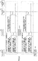
- FIG. 6 is a sequence diagram illustrating an example of an operation of the position management system according to the first embodiment. An operation in which the position management system specifies a position of the transmitter 10 will be described with reference to FIG. 6 .
- an antenna A and an antenna B are connected to the receiver 20. Each of the antenna A and the antenna B has different directivity, and the antenna A and the antenna B have a directivity pattern A and a directivity pattern B respectively.
- the antenna A is a flat antenna, for example, and has a directivity pattern of a wide beam width.
- the antenna B is a Yagi antenna, for example, and has a directivity pattern of a narrow beam width.
- the antenna B has a narrow beam width and has high gain, it is assumed that the antenna B can receive a radio signal from a further location (for example, 100 to 200 m away).
- the present example of operation describes a case in which five transmitters 10 (10 1 to 10 5 ) are present, and in which the transmitters 10 (10 1 to 10 5 ) are located at positions illustrated in FIG. 7 .
- the radio communication unit 201 in the receiver 20 switches an antenna to be used to the antenna A, receives a BLE radio signal transmitted from each of the transmitters 10, and obtains an ID of each of the transmitters 10 contained in the BLE radio signal. Also, the receiving strength measurement section 211 measures receiving strength of the BLE radio signal transmitted from each of the transmitters 10. Next, the radio communication unit 201 establishes connection with each of the transmitters 10, and receives data from each of the transmitters 10. The data contains, for example, a status (such as a remaining amount of a battery) of the transmitter 10, output values of various sensors in the transmitter 10 (or connected to the transmitter 10), and the like.
- a status such as a remaining amount of a battery
- the transmitting unit 202 in the receiver 20 transmits the transmitter information, for each transmitter 10, to the collector 30.
- the receiving unit 301 in the collector 30 stores the transmitter information received from the receiver 20 into the storage unit 302.
- the transmitter information includes an ID of a transmitter, information for identifying an antenna used for receiving a radio signal ("antenna A" at this step), receiving strength of the radio signal, and data received from the transmitter 10. If, at step S11, a radio signal is not received from a certain transmitter 10, or if an ID of the transmitter 10 cannot be obtained because of low receiving quality of a radio signal, the transmitter information of the transmitter 10 is not transmitted to the collector 30.
- the radio communication unit 201 switches an antenna to be used from the antenna A to the antenna B, and receives a BLE radio signal transmitted from each of the transmitters 10. Note that the switching of the antenna may be performed by the radio communication unit 201, or performed by a user.
- step S21 and step S22 are the same as the operations performed at step S11 and step S12 respectively, except that an antenna to be used is different. Thus, because the operations performed by the radio communication unit 201 are the same, specific descriptions about step S21 and step S22 will be omitted.
- the position specifying unit 303 in the collector 30 specifies a position of each of the transmitters 10 1 to 10 5 , based on the transmitter information of each of the transmitters 10 1 to 10 5 .
- a concrete method of specifying a position of each of the transmitters 10 1 to 10 5 will be described with reference to FIG. 7 .
- magnitude of receiving strength is expressed by using a word of "large”, “moderate”, or “small” for convenience.
- receiving strength represented by a numerical value in a unit of, for example, milliwatt (mW) or dBm, may be stored in the transmitter information.
- receiving strength of a radio signal from the transmitter 10 1 is large because the transmitter 10 1 is positioned in vicinity of the antenna A.
- the transmitter 10 2 is positioned in a location slightly apart from the antenna A within a range of the directivity pattern A, receiving strength of a radio signal from the transmitter 10 2 is moderate.
- the transmitter 10 3 is positioned in a location apart from the antenna A within the range of the directivity pattern A, receiving strength of a radio signal from the transmitter 10 3 is small.
- the transmitters 10 4 and 10 5 because the transmitters 10 4 and 10 5 are too far from the antenna A, a radio signal from the transmitter 10 4 or 10 5 cannot be received by the antenna A (that is, the antenna A cannot detect presence of the transmitter 10 4 or 10 5 ).
- the transmitter information of each of the transmitters 10 1 to 10 3 is stored in the collector 30, and the receiving strengths contained in the respective transmitter information of the transmitters 10 1 to 10 3 are "large”, “moderate”, and "small", respectively.
- receiving strength of a radio signal from the transmitter 10 1 is large because the transmitter 10 1 is positioned in vicinity of the antenna B within a range of the directivity pattern B.
- the transmitters 10 3 and 10 4 are positioned within the range of the directivity pattern B but are at a location slightly apart from the antenna B, receiving strength of a radio signal from the transmitter 10 3 and receiving strength of a radio signal from the transmitter 10 4 are moderate.
- the transmitter 10 5 is positioned within the range of the directivity pattern B but is at a location apart from the antenna B, receiving strength of a radio signal from the transmitter 10 5 is small.
- the transmitter 10 2 is out of the range of the directivity pattern of the antenna B, a radio signal from the transmitter 10 2 cannot be received by the antenna B (that is, the antenna B cannot detect presence of the transmitter 10 2 ).
- the transmitter information of each of the transmitters 10 1 , 10 3 , 10 4 , and 10 5 is stored in the collector 30, and the receiving strengths contained in the respective transmitter information of the transmitters 10 1 , 10 3 , 10 4 , and 10 5 are "large”, "moderate”, “moderate”, and "small", respectively.
- receiving strength of a radio signal from the transmitter 10 1 which is obtained by using the antenna A is “large”
- receiving strength of a radio signal from the transmitter 10 1 which is obtained by using the antenna B is "large”. That is, the position specifying unit 303 can specify that the transmitter 10 1 is positioned in the vicinity of the antenna A and the antenna B. Further, receiving strength of a radio signal from the transmitter 10 2 which is obtained by using the antenna A is "moderate”, and a radio signal from the transmitter 10 2 cannot be received when the antenna B is used. That is, the position specifying unit 303 can specify that the transmitter 10 2 is positioned at a location slightly apart from the antenna A within a range of the directivity pattern A, and out of a range of the directivity pattern of the antenna B.
- receiving strength of a radio signal from the transmitter 10 3 which is obtained by using the antenna A is "small"
- receiving strength of a radio signal from the transmitter 10 3 which is obtained by using the antenna B is "moderate”. That is, the position specifying unit 303 can specify that the transmitter 10 3 is positioned at a location apart from the antenna A within the range of the directivity pattern A, and slightly apart from the antenna B within the range of the directivity pattern B. Further, a radio signal from the transmitter 10 4 cannot be received when the antenna A is used, and receiving strength of a radio signal from the transmitter 10 4 which is obtained by using the antenna B is "moderate".
- the position specifying unit 303 can specify that the transmitter 10 4 is positioned at a location out of a range of the directivity pattern A, and slightly apart from the antenna B within a range of the directivity pattern B. Similarly, a radio signal from the transmitter 10 5 cannot be received when the antenna A is used, and receiving strength of a radio signal from the transmitter 10 5 which is obtained by using the antenna B is "small". That is, the position specifying unit 303 can specify that the transmitter 10 4 is positioned at a location out of a range of the directivity pattern A, and apart from the antenna B within a range of the directivity pattern B.
- the position management system according to the first embodiment can specify a position of each transmitter 10, by measuring receiving strengths of BLE radio signals by using multiple antennas each having a different directivity pattern. Also, because the position management system can accumulate transmitter information of each transmitter 10 in the collector 30, the accumulated data can be utilized for various types of analysis.
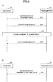
- the above first embodiment describes a case in which a data reception according to the conventional BLE is performed. That is, at step S11 and step S21, the radio communication unit 201 in the receiver 20 receives data from each of the transmitters 10, by establishing connection with each transmitter 10. More specifically, as illustrated in FIG. 8 (a) , the radio communication unit 201 in the receiver 20 receives an ID of the transmitter 10 contained in an advertising signal (may also be referred to as an advertising packet) for BLE (S31), and by transmitting a connection request to the transmitter 10 having the ID (S32), connection is established between the receiver 20 and the transmitter 10 (S33). The radio communication unit 201 in the receiver 20 receives data from the transmitter 10 by using the established connection (S34).
- an advertising signal may also be referred to as an advertising packet
- the radio communication unit 201 in the receiver 20 can receive data from each of the transmitters 10 without establishing connection with the transmitters 10. More specifically, as illustrated in FIG. 8 (b) , the transmitter 10 transmits an advertising signal containing an ID of the transmitter 10 and data to be transmitted. The radio communication unit 201 in the receiver 20 can receive the ID of the transmitter 10 and the data simultaneously, by receiving the advertising signal (S41).
- the radio communication unit 101 is configured to transmit an advertising signal for BLE (may also be referred to as a "BLE advertising signal") generated by the signal generating unit 102 by radio.
- BLE advertising signal may also be referred to as a "BLE advertising signal” generated by the signal generating unit 102 by radio.
- the signal generating unit 102 generates the advertising signal for BLE which contains information for identifying the transmitter 10 (an ID of the transmitter 10) and certain information (a state of the transmitter 10 and output values of various sensors), and passes the generated advertising signal to the radio communication unit 101.
- FIG. 9 A format of an advertising signal specified in Bluetooth 4.0 and iBeacon (registered trademark) is illustrated in FIG. 9 (a) .
- a header includes Preamble and Access Address which are specified in Bluetooth 4.0.
- a "unique ID” is specifically a UUID (Universal Unique Identifier) of 128 bits, and each of a "Major ID” and a “Minor ID” is an identifier of 16 bits.
- UUID Universal Unique Identifier
- FIG. 9 (b) A format of the advertising signal used in the second embodiment is illustrated in FIG. 9 (b) .
- a format of a 128-bit field for storing a "unique ID" is modified such that data can be stored in the 128-bit field.
- FIG. 9 (b) illustrates a case in which "Data A" and "Data B" are stored in the 128-bit field
- the 128-bit field may be configured such that only one data item can be stored, or may be configured such that more than two data items can be stored.
- the information for identifying the transmitter 10 (the ID of the transmitter 10)
- a set of the "unique ID”, the "Major ID”, and the “Minor ID”, or a set of the "Major ID” and the “Minor ID” may be used.
- the "unique ID” alone may be used as the information for identifying the transmitter 10.
- FIG. 10 is a sequence diagram illustrating an example of an operation of the position management system according to the second embodiment. With respect to a process step in FIG. 10 same as that in FIG. 6 , the same reference symbol is assigned, and the description of the process will be omitted.
- the radio communication unit 201 in the receiver 20 switches an antenna to be used to the antenna A, receives a BLE advertising signal transmitted from each transmitter 10, and obtains an ID of the transmitter 10 and data contained in the BLE advertising signal.
- the data contains, for example, a status (such as a remaining amount of a battery) of the transmitter 10, output values of various sensors in the transmitter 10 (or connected to the transmitter 10), and the like.
- the receiving strength measurement section 211 measures receiving strength of the BLE advertising signal transmitted from each of the transmitters 10.
- step S61 Operations performed at step S61 are the same as those performed at step S51, except that the antenna to be used is different. Thus, detailed descriptions about step S61 will be omitted.
- the position management system according to the second embodiment can specify a position of each transmitter 10, by measuring receiving strengths of BLE radio signals by using multiple antennas each having a different directivity pattern. Also, because the position management system can accumulate transmitter information of each transmitter 10 in the collector 30, the accumulated data can be utilized for various types of analysis. Further, as the receiver 20 can receive data from each transmitter 10 without establishing connection with the transmitters 10, a processing workload of the receiver 20 can be reduced as compared with the first embodiment.
- conventional BLE is designed based on a premise that a communication is performed between the receiver 20 and a small number of transmitters 10, the receiver 20 needs to establish connection with each of the transmitters 10 in order to obtain data from the transmitters 10. Accordingly, conventional BLE is not suitable for being applied to management or data collection of a large number of articles in logistics services. Rather, other products such as an active-type RFID product have been suitable for the management or the data collection of a large number of articles.
- the second embodiment enables data transmission using a BLE advertising signal, the management or the data collection of a large number of articles can be realized by using BLE, which is a more generic technology.
- the transmitter 10 transmits the BLE advertising signal described in the second embodiment
- the receiver 20 receives the BLE advertising signals transmitted from the transmitter 10, through a single antenna. That is, the third embodiment differs from the second embodiment in that the receiver 20 in the third embodiment receives the BLE advertising signals through a single antenna, whereas the receiver in the second embodiment receives the BLE advertising signals through multiple antennas. What is not mentioned in the second embodiment may be the same as that in the first embodiment.
- the single antenna employed in the third embodiment may be a flat antenna or a Yagi antenna. However, any types of antennas other than a flat antenna or a Yagi antenna may be used.
- the radio communication unit 201 is configured to receive a BLE radio signal transmitted from the transmitter 10 via the single antenna.
- the receiving strength measurement section 211 is configured to measure receiving strength (such as RSSI) of a BLE radio signal.
- the transmitting unit 202 is configured to transmit, to the collector 30, the transmitter information including an antenna used for receiving a BLE radio wave, receiving strength of the BLE radio wave, and an ID of the transmitter 10. Note that "the information about an antenna used for receiving a BLE radio wave" may be omitted from the transmitter information.
- the receiving unit 301 is configured to receive the transmitter information from the receiver 20 and to store the transmitter information into the storage unit 302.
- the position specifying unit 303 is configured to extract the transmitter information of a specific transmitter 10, and with respect to the transmitter 10 of which the transmitter information is extracted, to specify a position of the specific transmitter 10 based on the receiving strength. Note that the position specifying unit 303 may be omitted from the collector 30 in the third embodiment. That is, the collector 30 according to the third embodiment may only have a function for accumulating the transmitter information.
- step S13, step S22 and step S61 are omitted.
- step S51 and step S12 are the same as those in the second embodiment, description of these steps will be omitted. Note that, at step S12, "the information about an antenna used for receiving a radio wave" may be omitted from the transmitter information.
- the position specifying unit 303 specifies a position of the receiver 20, based on the receiving strength contained in the transmitter information. For example, in accordance with magnitude of the receiving strength, the position specifying unit 303 can specify whether the transmitter 10 is in vicinity of an antenna connected to the receiver 20 within a range of a directivity pattern of the antenna, the transmitter 10 is slightly apart from the antenna within the range of the directivity pattern of the antenna, the transmitter 10 is apart from the antenna within the range of the directivity pattern of the antenna, or the transmitter 10 is out of range of the directivity pattern of the antenna.
- a method of specifying position by the position specifying unit 303 is not limited to the method described above, and the position specifying unit 303 may specify a position in a finer granularity. Note that an operation at step S31 may be omitted.
- the position management system according to the third embodiment can specify a position of each transmitter 10, by measuring receiving strength of a BLE radio signal by using a single antenna. Also, because the position management system can accumulate transmitter information of each transmitter 10 in the collector 30, the accumulated data can be utilized for various types of analysis. Further, as the receiver 20 can receive data from each transmitter 10 without establishing connection with the transmitters 10, a processing workload of the receiver 20 can be reduced as compared with the first embodiment.
- the radio communication unit 201 is an example of a signal receiving means (unit).
- the position specifying unit 303 is an example of a specifying means (unit).
- the signal generating unit 102 is an example of a generating means (unit).
- the radio communication unit 101 is an example of a transmitting means (unit).
Landscapes
- Engineering & Computer Science (AREA)
- Physics & Mathematics (AREA)
- General Physics & Mathematics (AREA)
- Radar, Positioning & Navigation (AREA)
- Remote Sensing (AREA)
- Signal Processing (AREA)
- Position Fixing By Use Of Radio Waves (AREA)
- Telephonic Communication Services (AREA)
- Arrangements For Transmission Of Measured Signals (AREA)
- Mobile Radio Communication Systems (AREA)
Claims (4)
- Positions-Spezifiziervorrichtung, die mit einem Sender (10), der Bluetooth-Niederenergie (BLE) unterstützt, kommunizieren kann, wobei die Positions-Spezifiziervorrichtung umfasst:ein Signalempfangsmittel (201), welches unter Verwendung einer Vielzahl von Antennen, die eine unterschiedliche Direktivität aufweisen, konfiguriert ist, BLE-Funksingale zu empfangen, die aus dem Sender gesendet werden, und jeweilige Empfangsstärken der BLE-Funksignale zu messen; undein Spezifiziermittel (303), das konfiguriert ist, eine Position des Senders zu spezifizieren, durch Vergleichen der jeweiligen Empfangsstärken, die durch jede der Vielzahl von Antennen gemessen werden;dadurch gekennzeichnet, dass das BLE-Funksignal einem Format eines Ankündigungspakets, das im BLE-Standard spezifiziert ist, genügt, wobei das Ankündigungspaket 128-Bit-Feld zum Speichern eines universellen eineindeutigen Identifizierers (UUID) beinhaltet;das BLE-Funksignal konfiguriert ist, Information zum identifizieren des Senders in einem Teil des 128-Bit-Felds zu speichern und an die Positions-Spezifiziervorrichtung zu sendende Sendedaten in einem verbleibenden Teil des 128-Bit-Felds zu speichern, wobei die Sendedaten ein Status des Senders oder einen Ausgabewert eines mit dem Sender verbundenen Sensors sind; unddas Signalempfangsmittel konfiguriert ist, durch Empfangen des BLE-Funksignals, die Information zum Identifizieren des Senders und der Sendedaten zu erhalten, ohne eine Verbindung zwischen der Positions-Spezifiziervorrichtung und dem Sender zu etablieren.
- Positions-Spezifiziervorrichtung gemäß Anspruch 1, wobei die Vielzahl von Antennen ein Satz einer flachen Antenne und einer Yagi-Antenne ist.
- Positionsverwaltungssystem, umfassend:die Positions-Spezifiziervorrichtung gemäß Anspruch 1; undeinen Sender, der Bluetooth-Niederenergie (BLE) unterstützt, beinhaltend:ein Erzeugungsmittel, das konfiguriert ist, ein Paket entsprechend dem Format des Ankündigungspakets, das im BLE-Standard spezifiziert ist, zu erzeugen, wobei das Paket Information zum Identifizieren des Senders in einem Teil eine 128-Bit-Felds zum Speichern eines universellen eineindeutigen Identifizierers (UUID) speichert, und Sendedaten des Senders in einem verbleibenden Teil des 128-Bit-Felds speichert, wobei die Sendedaten ein Status des Senders oder ein Ausgabewert eines mit dem Sender verbundenen Sensors sind; undein Sendemittel, das konfiguriert ist, das durch das Erzeugungsmittel erzeugte Paket zu senden.
- Computerprogramm, um einen Prozessor (1001) zu veranlassen, die durch das in der Positions-Spezifiziervorrichtung gemäß Anspruch 1 oder 2 enthaltenen Mittel ausgeführten Prozesse zu verkörpern.
Applications Claiming Priority (1)
| Application Number | Priority Date | Filing Date | Title |
|---|---|---|---|
| PCT/JP2016/063186 WO2017187551A1 (ja) | 2016-04-27 | 2016-04-27 | 位置特定装置及びプログラム |
Publications (3)
| Publication Number | Publication Date |
|---|---|
| EP3451012A1 EP3451012A1 (de) | 2019-03-06 |
| EP3451012A4 EP3451012A4 (de) | 2019-12-25 |
| EP3451012B1 true EP3451012B1 (de) | 2020-10-28 |
Family
ID=60160332
Family Applications (1)
| Application Number | Title | Priority Date | Filing Date |
|---|---|---|---|
| EP16900423.1A Active EP3451012B1 (de) | 2016-04-27 | 2016-04-27 | Positionsspezifizierungsvorrichtung und -programm |
Country Status (7)
| Country | Link |
|---|---|
| US (1) | US10670686B2 (de) |
| EP (1) | EP3451012B1 (de) |
| JP (1) | JP6746693B2 (de) |
| CN (1) | CN109073730A (de) |
| AU (1) | AU2016404348B2 (de) |
| DK (1) | DK3451012T3 (de) |
| WO (1) | WO2017187551A1 (de) |
Families Citing this family (1)
| Publication number | Priority date | Publication date | Assignee | Title |
|---|---|---|---|---|
| JP7438750B2 (ja) * | 2019-12-26 | 2024-02-27 | Tdk株式会社 | 通信装置、通信システム、及び通信方法 |
Family Cites Families (20)
| Publication number | Priority date | Publication date | Assignee | Title |
|---|---|---|---|---|
| JPH08248116A (ja) * | 1996-01-12 | 1996-09-27 | Susumu Sakuma | 電波を用いた移動体の位置確認システム |
| US7359718B2 (en) * | 2004-04-30 | 2008-04-15 | Hong Kong Applied Science And Technology Research Institute Co., Ltd. | Location determination and location tracking in wireless networks |
| CN102483452A (zh) * | 2009-06-30 | 2012-05-30 | 诺基亚公司 | 装置和方法 |
| JP5647839B2 (ja) * | 2010-09-13 | 2015-01-07 | ラピスセミコンダクタ株式会社 | 無線キーシステム及びキー位置判定方法 |
| US8723730B2 (en) * | 2011-07-27 | 2014-05-13 | Exelis Inc. | System and method for direction finding and geolocation of emitters based on line-of-bearing intersections |
| GB201208294D0 (en) * | 2012-05-11 | 2012-06-20 | Jacktrak Ltd | A communication device |
| US8847754B2 (en) * | 2012-11-15 | 2014-09-30 | James Buchheim | Locator beacon and radar application for mobile device |
| JP6158547B2 (ja) * | 2013-03-19 | 2017-07-05 | 株式会社エイビット | 物体探索システム |
| JP6204073B2 (ja) * | 2013-05-31 | 2017-09-27 | 株式会社Nttドコモ | 無線タグ捜索方法およびその装置 |
| JP6059607B2 (ja) * | 2013-06-10 | 2017-01-11 | 株式会社Nttドコモ | 無線タグ捜索方法およびその装置 |
| EP3060935B1 (de) * | 2013-10-25 | 2017-12-20 | Cubic Corporation | Positionierungssystem mit drahtlosen baken mit unterschiedlichen sendeleistungspegeln |
| JP6348749B2 (ja) * | 2014-03-31 | 2018-06-27 | 国立大学法人 東京大学 | 移動体装置 |
| JP2015195433A (ja) | 2014-03-31 | 2015-11-05 | 株式会社Nttドコモ | 端末装置、及び着信制御方法 |
| US9385821B2 (en) * | 2014-07-16 | 2016-07-05 | Excaliber IP, LLC | System and method for calibrating bluetooth low energy signal strengths |
| CN204154894U (zh) * | 2014-07-28 | 2015-02-11 | 北京升哲科技有限公司 | 基于多种天线的室内场所定位系统及其定位信标设备 |
| EP3167303B1 (de) * | 2014-08-18 | 2021-09-29 | MEDIATEK Inc. | Peilantennenformat |
| CN105516887B (zh) * | 2014-09-25 | 2019-03-26 | 阿里巴巴集团控股有限公司 | 基于蓝牙的定位方法及其装置 |
| US20160183045A1 (en) * | 2014-12-17 | 2016-06-23 | AthenTek Inc. | Positioning device and positioning method thereof |
| CN105306109A (zh) * | 2015-09-17 | 2016-02-03 | 北京自在科技有限责任公司 | 一种低功耗蓝牙设备及低功耗蓝牙设备天线切换方法 |
| CN105424030B (zh) * | 2015-11-24 | 2018-11-09 | 东南大学 | 基于无线指纹和mems传感器的融合导航装置和方法 |
-
2016
- 2016-04-27 JP JP2018514015A patent/JP6746693B2/ja active Active
- 2016-04-27 EP EP16900423.1A patent/EP3451012B1/de active Active
- 2016-04-27 AU AU2016404348A patent/AU2016404348B2/en not_active Ceased
- 2016-04-27 DK DK16900423.1T patent/DK3451012T3/da active
- 2016-04-27 WO PCT/JP2016/063186 patent/WO2017187551A1/ja not_active Ceased
- 2016-04-27 CN CN201680084922.2A patent/CN109073730A/zh active Pending
-
2018
- 2018-10-19 US US16/164,912 patent/US10670686B2/en not_active Expired - Fee Related
Non-Patent Citations (1)
| Title |
|---|
| None * |
Also Published As
| Publication number | Publication date |
|---|---|
| AU2016404348B2 (en) | 2019-09-12 |
| CN109073730A (zh) | 2018-12-21 |
| US20190049546A1 (en) | 2019-02-14 |
| DK3451012T3 (da) | 2020-12-21 |
| JP6746693B2 (ja) | 2020-08-26 |
| EP3451012A4 (de) | 2019-12-25 |
| AU2016404348A1 (en) | 2018-11-15 |
| WO2017187551A1 (ja) | 2017-11-02 |
| JPWO2017187551A1 (ja) | 2019-03-14 |
| US10670686B2 (en) | 2020-06-02 |
| EP3451012A1 (de) | 2019-03-06 |
Similar Documents
| Publication | Publication Date | Title |
|---|---|---|
| US11378641B2 (en) | Asset location using direction finding features | |
| EP3304121B1 (de) | Systeme und verfahren zur ortung und bestimmung der ausrichtung einer handhaltbaren vorrichtung | |
| JP2006503286A (ja) | 無線ローカルエリアネットワーク(wlan)チャネル無線周波数識別(rfid)タグシステムおよび方法 | |
| EP3387847B1 (de) | Verfahren und vorrichtung zur bereitstellung eines dienstes in einem drahtlosen netzwerk | |
| EP3640848B1 (de) | Verfahren, endgerät und system zur artikelverarbeitung mittels rfid- und lpwan-technologie | |
| US11843934B2 (en) | Methods and systems for tracking of assets and user navigation | |
| US12250659B2 (en) | Methods and systems for tracking of assets and user navigation | |
| US20110317594A1 (en) | Hybrid architecture for radio frequency identification and packet radio communication | |
| Kwiecień et al. | Reliability of bluetooth smart technology for indoor localization system | |
| US8461994B2 (en) | RF receiver and RFID/USN system having the same | |
| CN102792346A (zh) | 用于传感器网络的发现及透明状态报告的方法和系统 | |
| CN111641430B (zh) | 一种信号调整方法及相关设备 | |
| EP2473864B1 (de) | Verfahren, vorrichtung und system zur drahtlosen signalspeicherung mit signalerkennungsauslösung | |
| US10670686B2 (en) | Position specifying device, transmitter, and non-transitory recording medium | |
| WO2021140983A1 (ja) | 物品管理システムおよび物品管理方法 | |
| US11824595B2 (en) | Locationing based on channel-specific gain | |
| WO2022272278A1 (en) | Systems and methods for electronic receipt transfer using ultrawideband radio technology | |
| Dasari et al. | Spectrum protection from micro-transmissions using distributed spectrum patrolling | |
| KR101055898B1 (ko) | 무선 통신 시스템에서의 거리 측정 장치 및 방법 | |
| US20080136637A1 (en) | Low latency listen before talk triggers | |
| HK1255510A1 (zh) | 物品处理方法、终端、系统及lpwan网关 | |
| KR102585968B1 (ko) | 위치 기반의 저전력 마케팅 단말, 서버 및 방법 | |
| CN105451168A (zh) | 一种定位方法及装置 |
Legal Events
| Date | Code | Title | Description |
|---|---|---|---|
| STAA | Information on the status of an ep patent application or granted ep patent |
Free format text: STATUS: THE INTERNATIONAL PUBLICATION HAS BEEN MADE |
|
| PUAI | Public reference made under article 153(3) epc to a published international application that has entered the european phase |
Free format text: ORIGINAL CODE: 0009012 |
|
| STAA | Information on the status of an ep patent application or granted ep patent |
Free format text: STATUS: REQUEST FOR EXAMINATION WAS MADE |
|
| 17P | Request for examination filed |
Effective date: 20181023 |
|
| AK | Designated contracting states |
Kind code of ref document: A1 Designated state(s): AL AT BE BG CH CY CZ DE DK EE ES FI FR GB GR HR HU IE IS IT LI LT LU LV MC MK MT NL NO PL PT RO RS SE SI SK SM TR |
|
| AX | Request for extension of the european patent |
Extension state: BA ME |
|
| DAV | Request for validation of the european patent (deleted) | ||
| DAX | Request for extension of the european patent (deleted) | ||
| A4 | Supplementary search report drawn up and despatched |
Effective date: 20191127 |
|
| RIC1 | Information provided on ipc code assigned before grant |
Ipc: G01S 5/12 20060101ALI20191121BHEP Ipc: H04M 11/00 20060101ALI20191121BHEP Ipc: G01S 5/02 20100101AFI20191121BHEP Ipc: G01S 3/18 20060101ALI20191121BHEP |
|
| GRAP | Despatch of communication of intention to grant a patent |
Free format text: ORIGINAL CODE: EPIDOSNIGR1 |
|
| STAA | Information on the status of an ep patent application or granted ep patent |
Free format text: STATUS: GRANT OF PATENT IS INTENDED |
|
| INTG | Intention to grant announced |
Effective date: 20200518 |
|
| RIN1 | Information on inventor provided before grant (corrected) |
Inventor name: AKANOMA, NOBUYUKI Inventor name: TAKAHATA, YASUYUKI Inventor name: FUKAYA, KAZUO |
|
| GRAS | Grant fee paid |
Free format text: ORIGINAL CODE: EPIDOSNIGR3 |
|
| GRAA | (expected) grant |
Free format text: ORIGINAL CODE: 0009210 |
|
| STAA | Information on the status of an ep patent application or granted ep patent |
Free format text: STATUS: THE PATENT HAS BEEN GRANTED |
|
| AK | Designated contracting states |
Kind code of ref document: B1 Designated state(s): AL AT BE BG CH CY CZ DE DK EE ES FI FR GB GR HR HU IE IS IT LI LT LU LV MC MK MT NL NO PL PT RO RS SE SI SK SM TR |
|
| REG | Reference to a national code |
Ref country code: GB Ref legal event code: FG4D |
|
| REG | Reference to a national code |
Ref country code: CH Ref legal event code: EP |
|
| REG | Reference to a national code |
Ref country code: AT Ref legal event code: REF Ref document number: 1328750 Country of ref document: AT Kind code of ref document: T Effective date: 20201115 |
|
| REG | Reference to a national code |
Ref country code: DE Ref legal event code: R096 Ref document number: 602016046934 Country of ref document: DE |
|
| REG | Reference to a national code |
Ref country code: IE Ref legal event code: FG4D |
|
| REG | Reference to a national code |
Ref country code: DK Ref legal event code: T3 Effective date: 20201217 |
|
| REG | Reference to a national code |
Ref country code: NL Ref legal event code: FP |
|
| REG | Reference to a national code |
Ref country code: AT Ref legal event code: MK05 Ref document number: 1328750 Country of ref document: AT Kind code of ref document: T Effective date: 20201028 |
|
| PG25 | Lapsed in a contracting state [announced via postgrant information from national office to epo] |
Ref country code: NO Free format text: LAPSE BECAUSE OF FAILURE TO SUBMIT A TRANSLATION OF THE DESCRIPTION OR TO PAY THE FEE WITHIN THE PRESCRIBED TIME-LIMIT Effective date: 20210128 Ref country code: RS Free format text: LAPSE BECAUSE OF FAILURE TO SUBMIT A TRANSLATION OF THE DESCRIPTION OR TO PAY THE FEE WITHIN THE PRESCRIBED TIME-LIMIT Effective date: 20201028 Ref country code: PT Free format text: LAPSE BECAUSE OF FAILURE TO SUBMIT A TRANSLATION OF THE DESCRIPTION OR TO PAY THE FEE WITHIN THE PRESCRIBED TIME-LIMIT Effective date: 20210301 Ref country code: FI Free format text: LAPSE BECAUSE OF FAILURE TO SUBMIT A TRANSLATION OF THE DESCRIPTION OR TO PAY THE FEE WITHIN THE PRESCRIBED TIME-LIMIT Effective date: 20201028 Ref country code: GR Free format text: LAPSE BECAUSE OF FAILURE TO SUBMIT A TRANSLATION OF THE DESCRIPTION OR TO PAY THE FEE WITHIN THE PRESCRIBED TIME-LIMIT Effective date: 20210129 |
|
| REG | Reference to a national code |
Ref country code: LT Ref legal event code: MG4D |
|
| PG25 | Lapsed in a contracting state [announced via postgrant information from national office to epo] |
Ref country code: IS Free format text: LAPSE BECAUSE OF FAILURE TO SUBMIT A TRANSLATION OF THE DESCRIPTION OR TO PAY THE FEE WITHIN THE PRESCRIBED TIME-LIMIT Effective date: 20210228 Ref country code: LV Free format text: LAPSE BECAUSE OF FAILURE TO SUBMIT A TRANSLATION OF THE DESCRIPTION OR TO PAY THE FEE WITHIN THE PRESCRIBED TIME-LIMIT Effective date: 20201028 Ref country code: PL Free format text: LAPSE BECAUSE OF FAILURE TO SUBMIT A TRANSLATION OF THE DESCRIPTION OR TO PAY THE FEE WITHIN THE PRESCRIBED TIME-LIMIT Effective date: 20201028 Ref country code: BG Free format text: LAPSE BECAUSE OF FAILURE TO SUBMIT A TRANSLATION OF THE DESCRIPTION OR TO PAY THE FEE WITHIN THE PRESCRIBED TIME-LIMIT Effective date: 20210128 Ref country code: AT Free format text: LAPSE BECAUSE OF FAILURE TO SUBMIT A TRANSLATION OF THE DESCRIPTION OR TO PAY THE FEE WITHIN THE PRESCRIBED TIME-LIMIT Effective date: 20201028 Ref country code: ES Free format text: LAPSE BECAUSE OF FAILURE TO SUBMIT A TRANSLATION OF THE DESCRIPTION OR TO PAY THE FEE WITHIN THE PRESCRIBED TIME-LIMIT Effective date: 20201028 Ref country code: SE Free format text: LAPSE BECAUSE OF FAILURE TO SUBMIT A TRANSLATION OF THE DESCRIPTION OR TO PAY THE FEE WITHIN THE PRESCRIBED TIME-LIMIT Effective date: 20201028 |
|
| PG25 | Lapsed in a contracting state [announced via postgrant information from national office to epo] |
Ref country code: HR Free format text: LAPSE BECAUSE OF FAILURE TO SUBMIT A TRANSLATION OF THE DESCRIPTION OR TO PAY THE FEE WITHIN THE PRESCRIBED TIME-LIMIT Effective date: 20201028 |
|
| REG | Reference to a national code |
Ref country code: DE Ref legal event code: R097 Ref document number: 602016046934 Country of ref document: DE |
|
| PG25 | Lapsed in a contracting state [announced via postgrant information from national office to epo] |
Ref country code: EE Free format text: LAPSE BECAUSE OF FAILURE TO SUBMIT A TRANSLATION OF THE DESCRIPTION OR TO PAY THE FEE WITHIN THE PRESCRIBED TIME-LIMIT Effective date: 20201028 Ref country code: CZ Free format text: LAPSE BECAUSE OF FAILURE TO SUBMIT A TRANSLATION OF THE DESCRIPTION OR TO PAY THE FEE WITHIN THE PRESCRIBED TIME-LIMIT Effective date: 20201028 Ref country code: LT Free format text: LAPSE BECAUSE OF FAILURE TO SUBMIT A TRANSLATION OF THE DESCRIPTION OR TO PAY THE FEE WITHIN THE PRESCRIBED TIME-LIMIT Effective date: 20201028 Ref country code: SM Free format text: LAPSE BECAUSE OF FAILURE TO SUBMIT A TRANSLATION OF THE DESCRIPTION OR TO PAY THE FEE WITHIN THE PRESCRIBED TIME-LIMIT Effective date: 20201028 Ref country code: SK Free format text: LAPSE BECAUSE OF FAILURE TO SUBMIT A TRANSLATION OF THE DESCRIPTION OR TO PAY THE FEE WITHIN THE PRESCRIBED TIME-LIMIT Effective date: 20201028 Ref country code: RO Free format text: LAPSE BECAUSE OF FAILURE TO SUBMIT A TRANSLATION OF THE DESCRIPTION OR TO PAY THE FEE WITHIN THE PRESCRIBED TIME-LIMIT Effective date: 20201028 |
|
| PLBE | No opposition filed within time limit |
Free format text: ORIGINAL CODE: 0009261 |
|
| STAA | Information on the status of an ep patent application or granted ep patent |
Free format text: STATUS: NO OPPOSITION FILED WITHIN TIME LIMIT |
|
| 26N | No opposition filed |
Effective date: 20210729 |
|
| PG25 | Lapsed in a contracting state [announced via postgrant information from national office to epo] |
Ref country code: AL Free format text: LAPSE BECAUSE OF FAILURE TO SUBMIT A TRANSLATION OF THE DESCRIPTION OR TO PAY THE FEE WITHIN THE PRESCRIBED TIME-LIMIT Effective date: 20201028 Ref country code: IT Free format text: LAPSE BECAUSE OF FAILURE TO SUBMIT A TRANSLATION OF THE DESCRIPTION OR TO PAY THE FEE WITHIN THE PRESCRIBED TIME-LIMIT Effective date: 20201028 |
|
| PG25 | Lapsed in a contracting state [announced via postgrant information from national office to epo] |
Ref country code: SI Free format text: LAPSE BECAUSE OF FAILURE TO SUBMIT A TRANSLATION OF THE DESCRIPTION OR TO PAY THE FEE WITHIN THE PRESCRIBED TIME-LIMIT Effective date: 20201028 Ref country code: MC Free format text: LAPSE BECAUSE OF FAILURE TO SUBMIT A TRANSLATION OF THE DESCRIPTION OR TO PAY THE FEE WITHIN THE PRESCRIBED TIME-LIMIT Effective date: 20201028 |
|
| PG25 | Lapsed in a contracting state [announced via postgrant information from national office to epo] |
Ref country code: LU Free format text: LAPSE BECAUSE OF NON-PAYMENT OF DUE FEES Effective date: 20210427 |
|
| PG25 | Lapsed in a contracting state [announced via postgrant information from national office to epo] |
Ref country code: LI Free format text: LAPSE BECAUSE OF NON-PAYMENT OF DUE FEES Effective date: 20210430 Ref country code: CH Free format text: LAPSE BECAUSE OF NON-PAYMENT OF DUE FEES Effective date: 20210430 |
|
| PG25 | Lapsed in a contracting state [announced via postgrant information from national office to epo] |
Ref country code: IE Free format text: LAPSE BECAUSE OF NON-PAYMENT OF DUE FEES Effective date: 20210427 |
|
| PG25 | Lapsed in a contracting state [announced via postgrant information from national office to epo] |
Ref country code: IS Free format text: LAPSE BECAUSE OF FAILURE TO SUBMIT A TRANSLATION OF THE DESCRIPTION OR TO PAY THE FEE WITHIN THE PRESCRIBED TIME-LIMIT Effective date: 20210228 |
|
| PG25 | Lapsed in a contracting state [announced via postgrant information from national office to epo] |
Ref country code: CY Free format text: LAPSE BECAUSE OF FAILURE TO SUBMIT A TRANSLATION OF THE DESCRIPTION OR TO PAY THE FEE WITHIN THE PRESCRIBED TIME-LIMIT Effective date: 20201028 |
|
| PGFP | Annual fee paid to national office [announced via postgrant information from national office to epo] |
Ref country code: NL Payment date: 20230428 Year of fee payment: 8 |
|
| PG25 | Lapsed in a contracting state [announced via postgrant information from national office to epo] |
Ref country code: HU Free format text: LAPSE BECAUSE OF FAILURE TO SUBMIT A TRANSLATION OF THE DESCRIPTION OR TO PAY THE FEE WITHIN THE PRESCRIBED TIME-LIMIT; INVALID AB INITIO Effective date: 20160427 |
|
| PGFP | Annual fee paid to national office [announced via postgrant information from national office to epo] |
Ref country code: FR Payment date: 20230421 Year of fee payment: 8 Ref country code: DE Payment date: 20230428 Year of fee payment: 8 |
|
| PGFP | Annual fee paid to national office [announced via postgrant information from national office to epo] |
Ref country code: BE Payment date: 20230427 Year of fee payment: 8 |
|
| PGFP | Annual fee paid to national office [announced via postgrant information from national office to epo] |
Ref country code: GB Payment date: 20230427 Year of fee payment: 8 |
|
| PG25 | Lapsed in a contracting state [announced via postgrant information from national office to epo] |
Ref country code: MK Free format text: LAPSE BECAUSE OF FAILURE TO SUBMIT A TRANSLATION OF THE DESCRIPTION OR TO PAY THE FEE WITHIN THE PRESCRIBED TIME-LIMIT Effective date: 20201028 |
|
| PG25 | Lapsed in a contracting state [announced via postgrant information from national office to epo] |
Ref country code: TR Free format text: LAPSE BECAUSE OF FAILURE TO SUBMIT A TRANSLATION OF THE DESCRIPTION OR TO PAY THE FEE WITHIN THE PRESCRIBED TIME-LIMIT Effective date: 20201028 |
|
| PG25 | Lapsed in a contracting state [announced via postgrant information from national office to epo] |
Ref country code: MT Free format text: LAPSE BECAUSE OF FAILURE TO SUBMIT A TRANSLATION OF THE DESCRIPTION OR TO PAY THE FEE WITHIN THE PRESCRIBED TIME-LIMIT Effective date: 20201028 |
|
| REG | Reference to a national code |
Ref country code: DE Ref legal event code: R119 Ref document number: 602016046934 Country of ref document: DE |
|
| REG | Reference to a national code |
Ref country code: NL Ref legal event code: MM Effective date: 20240501 |
|
| GBPC | Gb: european patent ceased through non-payment of renewal fee |
Effective date: 20240427 |
|
| REG | Reference to a national code |
Ref country code: BE Ref legal event code: MM Effective date: 20240430 |
|
| PG25 | Lapsed in a contracting state [announced via postgrant information from national office to epo] |
Ref country code: DE Free format text: LAPSE BECAUSE OF NON-PAYMENT OF DUE FEES Effective date: 20241105 |
|
| PG25 | Lapsed in a contracting state [announced via postgrant information from national office to epo] |
Ref country code: NL Free format text: LAPSE BECAUSE OF NON-PAYMENT OF DUE FEES Effective date: 20240501 Ref country code: BE Free format text: LAPSE BECAUSE OF NON-PAYMENT OF DUE FEES Effective date: 20240430 |
|
| PG25 | Lapsed in a contracting state [announced via postgrant information from national office to epo] |
Ref country code: GB Free format text: LAPSE BECAUSE OF NON-PAYMENT OF DUE FEES Effective date: 20240427 |
|
| PG25 | Lapsed in a contracting state [announced via postgrant information from national office to epo] |
Ref country code: FR Free format text: LAPSE BECAUSE OF NON-PAYMENT OF DUE FEES Effective date: 20240430 |
|
| PG25 | Lapsed in a contracting state [announced via postgrant information from national office to epo] |
Ref country code: NL Free format text: LAPSE BECAUSE OF NON-PAYMENT OF DUE FEES Effective date: 20240501 Ref country code: GB Free format text: LAPSE BECAUSE OF NON-PAYMENT OF DUE FEES Effective date: 20240427 Ref country code: FR Free format text: LAPSE BECAUSE OF NON-PAYMENT OF DUE FEES Effective date: 20240430 Ref country code: DE Free format text: LAPSE BECAUSE OF NON-PAYMENT OF DUE FEES Effective date: 20241105 Ref country code: BE Free format text: LAPSE BECAUSE OF NON-PAYMENT OF DUE FEES Effective date: 20240430 |
|
| PGFP | Annual fee paid to national office [announced via postgrant information from national office to epo] |
Ref country code: DK Payment date: 20250429 Year of fee payment: 10 |