EP3450908A1 - Rotary forge device testing device, testing tool, testing method, bearing unit manufacturing device, and bearing unit manufacturing method - Google Patents
Rotary forge device testing device, testing tool, testing method, bearing unit manufacturing device, and bearing unit manufacturing method Download PDFInfo
- Publication number
- EP3450908A1 EP3450908A1 EP17827627.5A EP17827627A EP3450908A1 EP 3450908 A1 EP3450908 A1 EP 3450908A1 EP 17827627 A EP17827627 A EP 17827627A EP 3450908 A1 EP3450908 A1 EP 3450908A1
- Authority
- EP
- European Patent Office
- Prior art keywords
- head
- central axis
- forging apparatus
- processing roll
- swing forging
- Prior art date
- Legal status (The legal status is an assumption and is not a legal conclusion. Google has not performed a legal analysis and makes no representation as to the accuracy of the status listed.)
- Withdrawn
Links
- 238000004519 manufacturing process Methods 0.000 title claims description 12
- 238000012360 testing method Methods 0.000 title abstract description 9
- 238000007689 inspection Methods 0.000 claims description 133
- 238000005242 forging Methods 0.000 claims description 95
- 238000005096 rolling process Methods 0.000 claims description 26
- 238000000034 method Methods 0.000 claims description 20
- 238000003825 pressing Methods 0.000 claims description 18
- 230000002093 peripheral effect Effects 0.000 claims description 12
- 238000001514 detection method Methods 0.000 claims description 7
- 230000008878 coupling Effects 0.000 claims description 3
- 238000010168 coupling process Methods 0.000 claims description 3
- 238000005859 coupling reaction Methods 0.000 claims description 3
- 238000007599 discharging Methods 0.000 abstract 1
- 210000003128 head Anatomy 0.000 description 99
- 230000008859 change Effects 0.000 description 4
- 230000003028 elevating effect Effects 0.000 description 4
- 230000008569 process Effects 0.000 description 4
- 230000007246 mechanism Effects 0.000 description 2
- 229910000831 Steel Inorganic materials 0.000 description 1
- 230000000694 effects Effects 0.000 description 1
- 210000000887 face Anatomy 0.000 description 1
- 239000000463 material Substances 0.000 description 1
- 239000007769 metal material Substances 0.000 description 1
- 239000010959 steel Substances 0.000 description 1
- 239000000725 suspension Substances 0.000 description 1
Images




Classifications
-
- B—PERFORMING OPERATIONS; TRANSPORTING
- B21—MECHANICAL METAL-WORKING WITHOUT ESSENTIALLY REMOVING MATERIAL; PUNCHING METAL
- B21J—FORGING; HAMMERING; PRESSING METAL; RIVETING; FORGE FURNACES
- B21J9/00—Forging presses
- B21J9/02—Special design or construction
- B21J9/06—Swaging presses; Upsetting presses
-
- G—PHYSICS
- G01—MEASURING; TESTING
- G01M—TESTING STATIC OR DYNAMIC BALANCE OF MACHINES OR STRUCTURES; TESTING OF STRUCTURES OR APPARATUS, NOT OTHERWISE PROVIDED FOR
- G01M13/00—Testing of machine parts
- G01M13/04—Bearings
-
- B—PERFORMING OPERATIONS; TRANSPORTING
- B21—MECHANICAL METAL-WORKING WITHOUT ESSENTIALLY REMOVING MATERIAL; PUNCHING METAL
- B21J—FORGING; HAMMERING; PRESSING METAL; RIVETING; FORGE FURNACES
- B21J9/00—Forging presses
- B21J9/02—Special design or construction
- B21J9/025—Special design or construction with rolling or wobbling dies
-
- B—PERFORMING OPERATIONS; TRANSPORTING
- B21—MECHANICAL METAL-WORKING WITHOUT ESSENTIALLY REMOVING MATERIAL; PUNCHING METAL
- B21J—FORGING; HAMMERING; PRESSING METAL; RIVETING; FORGE FURNACES
- B21J9/00—Forging presses
- B21J9/10—Drives for forging presses
- B21J9/20—Control devices specially adapted to forging presses not restricted to one of the preceding subgroups
-
- B—PERFORMING OPERATIONS; TRANSPORTING
- B60—VEHICLES IN GENERAL
- B60B—VEHICLE WHEELS; CASTORS; AXLES FOR WHEELS OR CASTORS; INCREASING WHEEL ADHESION
- B60B27/00—Hubs
- B60B27/0005—Hubs with ball bearings
-
- B—PERFORMING OPERATIONS; TRANSPORTING
- B60—VEHICLES IN GENERAL
- B60B—VEHICLE WHEELS; CASTORS; AXLES FOR WHEELS OR CASTORS; INCREASING WHEEL ADHESION
- B60B27/00—Hubs
- B60B27/0078—Hubs characterised by the fixation of bearings
- B60B27/0084—Hubs characterised by the fixation of bearings caulking to fix inner race
-
- G—PHYSICS
- G01—MEASURING; TESTING
- G01B—MEASURING LENGTH, THICKNESS OR SIMILAR LINEAR DIMENSIONS; MEASURING ANGLES; MEASURING AREAS; MEASURING IRREGULARITIES OF SURFACES OR CONTOURS
- G01B11/00—Measuring arrangements characterised by the use of optical techniques
- G01B11/26—Measuring arrangements characterised by the use of optical techniques for measuring angles or tapers; for testing the alignment of axes
-
- G—PHYSICS
- G01—MEASURING; TESTING
- G01B—MEASURING LENGTH, THICKNESS OR SIMILAR LINEAR DIMENSIONS; MEASURING ANGLES; MEASURING AREAS; MEASURING IRREGULARITIES OF SURFACES OR CONTOURS
- G01B11/00—Measuring arrangements characterised by the use of optical techniques
- G01B11/26—Measuring arrangements characterised by the use of optical techniques for measuring angles or tapers; for testing the alignment of axes
- G01B11/27—Measuring arrangements characterised by the use of optical techniques for measuring angles or tapers; for testing the alignment of axes for testing the alignment of axes
- G01B11/272—Measuring arrangements characterised by the use of optical techniques for measuring angles or tapers; for testing the alignment of axes for testing the alignment of axes using photoelectric detection means
-
- G—PHYSICS
- G01—MEASURING; TESTING
- G01M—TESTING STATIC OR DYNAMIC BALANCE OF MACHINES OR STRUCTURES; TESTING OF STRUCTURES OR APPARATUS, NOT OTHERWISE PROVIDED FOR
- G01M17/00—Testing of vehicles
- G01M17/007—Wheeled or endless-tracked vehicles
Definitions
- the present invention relates to an inspection device of a swing forging apparatus, an inspection tool of the swing forging apparatus, an inspection method of the swing forging apparatus, a manufacturing apparatus of a bearing unit, and a manufacturing method of a bearing unit.
- FIG. 8 depicts an example of a rolling bearing unit for wheel support of a vehicle.
- the rolling bearing unit for wheel support includes an outer ring 1, a hub 2, and a plurality of rolling elements 5, 5.
- the outer ring 1 is fitted and fixed to a suspension, so that it is not rotated even during the using.
- the hub 2 is configured to rotate together with a wheel with supporting and fixing the wheel thereto.
- the plurality of rolling elements 5, 5 is provided between double rows of outer races 3a, 3b provided on an inner peripheral surface of the outer ring 1 and double rows of inner races 4a, 4b provided on an outer peripheral surface of the hub 2.
- the hub 2 is configured by coupling and fixing a hub main body 6 having the axially outboard (a left side in FIG. 8 ) inner race 4a directly formed on an outer peripheral surface thereof and an inner ring 7 having the axially inboard (a right side in FIG. 8 ) inner race 4b directly formed on an outer peripheral surface thereof.
- the inner ring 7 is externally fitted to a part close to an axially inboard end portion of the hub main body 6.
- An axially inboard end face of the inner ring 7 is pressed by a swaging part 9 formed by plastically deforming a cylindrical part 8, which is provided at the axially inboard end portion of the hub main body 6, in a radially outward direction.
- the swaging part 9 can be formed by a variety of known swing forging apparatuses disclosed in Patent Document 1 and the like.
- the swing forging apparatus includes a head and a processing roll.
- the head is configured to rotatively drive about a central axis thereof.
- the processing roll is supported to the head so that it can be rotated about a central axis thereof at a state where the central axis is inclined relative to the central axis of the head.
- the processing roll When forming the swaging part 9 at the axially inboard end portion of the hub main body 6, which is a workpiece (an object to be processed), the processing roll is pressed to a circumferential portion of an axially inboard end portion of the cylindrical part 8 at a state where the central axis of the hub main body 6 is made to coincide with the central axis of the head.
- the head is rotatively driven about the central axis of the head, so that the processing roll is rotated (revolved) about the central axis of the head and is also rotated on the central axis of the processing roll.
- the processing of plastically deforming the cylindrical part 8 in the radially outward direction progresses partially and continuously in a circumferential direction, so that the swaging part 9 is formed.
- a test of forming the swaging part 9 is performed using the swing forging apparatus after completion, so that when it is not possible to appropriately form the swaging part 9, an operation of changing a processing condition or replacing a component of the swing forging apparatus. Then, the test and the operation are repeated to perform the management for appropriately forming the swaging part 9.
- the rolling bearing unit for wheel support that is provided for the test is discarded.
- the present invention has been made in view of the above situations, and an object thereof is to implement an apparatus (a tool) and a method for precisely estimating a position of a swing center and an inclination angle of a processing roll configuring a swing forging apparatus after completion.
- a swing forging apparatus of the present invention includes a head and a processing roll.
- the head is configured to rotatively drive about a central axis thereof.
- the processing roll is supported to the head so that it can be rotated about a central axis of the processing roll at a state where the central axis is inclined relative to the central axis of the head.
- the head When using the swing forging apparatus, the head is rotatively driven about the central axis of the head with the processing roll being pressed to a workpiece, so that the processing roll is rotated about the central axis of the head and is also rotated about the central axis of the processing roll.
- An inspection device of a swing forging apparatus includes an inspection tool and a laser irradiation surface.
- the inspection tool When inspecting the swing forging apparatus, the inspection tool is supported to the head to which the processing roll is not supported, with the substantially same condition as the processing roll, and has a function of emitting a laser beam onto a central axis of the inspection tool.
- the laser irradiation surface is arranged so that a relative position thereof to the head in an axial direction of the head can be changed and the laser beam can be irradiated thereto when inspecting the swing forging apparatus.
- a sensor arranged to detect an irradiation position of the laser beam to the laser irradiation surface when inspecting the swing forging apparatus may be provided.
- a calculator may be provided.
- the calculator has functions of, when inspecting the swing forging apparatus, at a state where the head is rotatively driven about a central axis thereof and a laser beam emitted from the inspection tool onto a central axis of the inspection tool is irradiated to the laser irradiation surface while applying a predetermined load (for example, a load to be applied to the processing roll when processing a workpiece by the processing roll) to the inspection tool or not applying the load, changing a radius of a locus of an irradiation position of the laser beam to the laser irradiation surface by changing a relative position between the head and the laser irradiation surface in the axial direction of the head, and obtaining a position of the locus (a point when a minimum radius becomes zero (0); a swing center of the inspection tool) having a minimum radius at a coordinate system set for the swing forging apparatus on the basis of a detection signal of the
- the position of the locus having the minimum radius may be estimated as a position of a swing center of the processing roll at a state where the processing roll is supported to the head.
- a calculator may be provided.
- the calculator has functions of, upon inspection of the swing forging apparatus, at a state where the head is rotatively driven about a central axis thereof and a laser beam emitted from the inspection tool onto a central axis of the inspection tool is irradiated to the laser irradiation surface while applying a predetermined load (for example, a load to be applied to the processing roll when processing a workpiece by the processing roll) to the inspection tool or not applying the load, when a locus of an irradiation position of the laser beam to the laser irradiation surface is changed by changing a relative position between the head and the laser irradiation surface in the axial direction of the head, obtaining a variation ⁇ R in the radius of the locus of the irradiation position on the basis of a detection signal of the sensor when the relative position is changed by a variation ⁇ L, and obtaining an inclination angle of
- the inclination angle of the central axis of the inspection tool relative to the central axis of the head may be estimated as an inclination angle of the central axis of the processing roll relative to the central axis of the head at a state where the processing roll is supported to the head.
- calculators of the third to sixth aspects may be independent of each other or may be singular.
- an inspection tool of a swing forging apparatus includes a head configured to rotatively drive about a central axis thereof, and a processing roll supported to the head so that it can be rotated about a central axis of the processing roll at a state where the central axis is inclined relative to the central axis of the head, wherein when inspecting the swing forging apparatus, the inspection tool is supported to the head to which the processing roll is not supported, with the substantially same condition as the processing roll, and has a function of emitting a laser beam onto a central axis of the inspection tool.
- an inspection method of a swing forging apparatus includes, when inspecting the swing forging apparatus by using the inspection device of the swing forging apparatus of the first to fourth aspects, at a state where the head is rotatively driven about a central axis thereof and a laser beam emitted from the inspection tool onto a central axis of the inspection tool is irradiated to the laser irradiation surface while applying a predetermined load (for example, a load to be applied to the processing roll when processing a workpiece by the processing roll) to the inspection tool or not applying the load, changing a radius of a locus of an irradiation position of the laser beam to the laser irradiation surface to minimize (including zero (0)) the locus by changing a relative position between the head and the laser irradiation surface in the axial direction of the head, and obtaining a position of the locus (a point when a minimum radius becomes zero (0); a swing center of the inspection tool) having the minimum radius at
- the locus of the irradiation position may be detected with operator's naked eyes or may be detected by the sensor. Also, the process of obtaining the position of the locus having the minimum radius may be performed by an operator or by the calculator.
- an inspection method of a swing forging apparatus includes, upon inspection of the swing forging apparatus by using the inspection device of the swing forging apparatus of the first to sixth aspects, at a state where the head is rotatively driven about a central axis thereof and a laser beam emitted from the inspection tool onto a central axis of the inspection tool is irradiated to the laser irradiation surface while applying a predetermined load (for example, a load to be applied to the processing roll when processing a workpiece by the processing roll) to the inspection tool or not applying the load, when a locus of an irradiation position of the laser beam to the laser irradiation surface is changed by changing a relative position between the head and the laser irradiation surface in the axial direction of the head, so that the relative position is changed by a variation ⁇ L, obtaining a variation ⁇ R in a radius of the locus of the irradiation position, and obtaining an inclination angle of the
- the locus of the irradiation position may be detected with operator's naked eyes or may be detected by the sensor. Also, the processes of obtaining the respective variations ⁇ L, ⁇ R and the inclination angle may be performed by an operator or by the calculator.
- the inspection device of the swing forging apparatus the inspection tool, and the inspection method of the present invention, it is possible to precisely estimate the position (the position at the coordinate system set for the swing forging apparatus) of the swing center of the processing roll configuring the swing forging apparatus after completion and the inclination angle of the processing roll.
- the present invention it is possible to obtain the position of the swing center of the inspection tool and the inclination angle of the central axis of the inspection tool by using the locus of the irradiation position of the laser beam to the laser irradiation surface.
- the inspection tool is supported to the head to which the processing roll is not supported, with the substantially same condition as the processing roll. For this reason, it is possible to precisely estimate the position of the swing center and the inclination angle of the central axis of the inspection tool obtained as described above, as the position of the swing center and the inclination angle of the central axis of the processing roll configuring the swing forging apparatus after completion.
- the position of the swing center and the inclination angle of the central axis of the inspection tool are obtained while applying the predetermined load (for example, a load F ⁇ to be applied to the processing roll when processing the workpiece by the processing roll) to the inspection tool
- the position of the swing center and the inclination angle of the central axis of the inspection tool obtained in this way can be precisely estimated as the position of the swing center and the inclination angle of the central axis of the processing roll at the state where the predetermined load is applied (for example, during shape forming of the workpiece when the predetermined load is the load F ⁇ ).
- FIGS. 1 to 7B An example of an embodiment of the present invention will be described with reference to FIGS. 1 to 7B .
- the swing forging apparatus can form the swaging part 9 of the rolling bearing unit for wheel support shown in FIG. 8 .
- the swing forging apparatus includes a base 10, a support column 11, a holder 12, a head 13, a head driving means 14, and a processing roll 15.
- the holder 12 is fixed to an upper surface of the base 10.
- the holder 12 can hold and fix the hub main body 6 configuring the rolling bearing unit for wheel support.
- the axially inboard end portion of the hub main body 6 held and fixed to holder 12 faces upward. Also, at a state where the hub main body 6 is held and fixed to the holder 12, both the central axes of the hub main body 6 is held and fixed to the holder 12 coincide with each other in an upper and lower direction.
- the head 13 is arranged above the holder 12.
- the head 13 is supported by the support column 11 fixed to the base 10, via the head driving means 14.
- a central axis ⁇ of the head 13 coincides with the central axis of the holder 12 (the central axis of the hub main body 6).
- the head 13 is provided on its lower surface with a holding concave hole 16 having s central axis inclined relative to the central axis ⁇ of the head 13.
- the head driving means 14 includes a spindle device 17 and a cylinder 18.
- the spindle device 17 is arranged in the upper and lower direction.
- the spindle device 17 can rotatively drive a spindle shaft (not shown) arranged at a radially central portion in a direct manner (without via a deceleration mechanism) by an electric motor 19 arranged at an upper end portion of the spindle device.
- the cylinder 18 is a hydraulic cylinder and can displace the spindle device 17 relative to the support column 11 in the upper and lower direction.
- the head 13 is coupled and fixed to a lower end portion of the spindle shaft of the spindle device 17. At this state, the head 13 can be rotatively driven about the central axis ⁇ by the spindle device 17 and can also be displaced in the upper and lower direction (an axial direction of the head) by the cylinder 18.
- the processing roll 15 includes a shaft part 20, a head part 21, and a pressing surface 22.
- the head part 21 is provided at a lower end portion of the shaft part 20 and has a diameter larger than the shaft part 20.
- the pressing surface 22 is provided over an entire circumference of a lower surface of the head part 21 and has a circular ring shape.
- the shaft part 20 of the processing roll 15 is inserted in the holding concave hole 16 of the head 13.
- an upper end portion of the shaft part 20 is rotatably supported by a thrust rolling bearing 23, and an axially intermediate portion of the shaft part 20 is rotatably supported by a radial rolling bearing 24. That is, at a state where the head part 21 protrudes from a lower surface of the head 13 and a central axis ⁇ of the processing roll is inclined relative to the central axis ⁇ of the head 13 by an inclination angle ⁇ , the processing roll 15 is supported to the head 13 to be rotatable about the central axis ⁇ .
- a method of forming the swaging part 9 at the axially inboard end portion of the hub main body 6, which is a workpiece, by the swing forging apparatus configured as described above is described.
- the hub main body 6 is held and fixed by the holder 12, so that the central axis of the hub main body 6 is made to coincide with the central axis ⁇ of the head 13, as shown in FIG. 2 .
- FIGS. 2 and 3 only the axially inboard end portion of the hub main body 6 and the inner ring 7 of the rolling bearing unit for wheel support are shown, and the other parts are not shown.
- the processing roll 15 is rotated (revolved) about the central axis ⁇ of the head 13 and is also rotated on the central axis ⁇ of the processing roll.
- the processing of plastically deforming the cylindrical part 8 in the radially outward direction progresses partially and continuously in the circumferential direction, so that the swaging part 9 is formed, as shown in FIG. 3 .
- the inspection device of the swing forging apparatus of the example is configured to obtain (to precisely estimate) a position of a swing center P of the processing roll 15 and an inclination angle ⁇ of the central axis ⁇ of the processing roll 15 relative to the central axis ⁇ of the head 13, for the swing forging apparatus after completion.
- the swing center P is an intersection point of the central axis ⁇ of the head 13 and the central axis ⁇ of the processing roll 15. Also, the position of the swing center P is a position at a coordinate system set for the swing forging apparatus, and in this example, changes as the cylinder 18 is driven by a command from a controller (a control unit) of the swing forging apparatus. Also, the position of the swing center P is a position of a height Z from a reference surface 34, which is an upper surface of the base 10.
- the inspection device of the swing forging apparatus of the example includes an inspection tool 25, a receiving stand 26, a laser irradiation surface 27, a sensor (not shown), and a computer (not shown) having a calculator.
- the inspection tool 25 When inspecting the swing forging apparatus, the inspection tool 25 is supported to the head 13 at a state where the processing roll 15 is not supported thereto, with the substantially same condition as the processing roll 15.
- the inspection tool 25 can emit a laser beam B L onto a central axis thereof (onto a central axis ⁇ A ).
- the inspection tool 25 includes an inspection roll part 29 and a laser generator 30.
- the inspection roll part 29 has substantially the same stiffness as the processing roll 15.
- the inspection roll part 29 has a shaft part 20a, a head part 21a, and a pressing surface 22a.
- the head part 21a is provided at a lower end portion of the shaft part 20a and has a diameter larger than the shaft part 20a.
- the pressing surface 22a is provided over an entire circumference of a lower surface of the head part 21a and has a circular ring shape.
- a shape of the pressing surface 22a is different from the pressing surface 22 of the processing roll 15 (i.e., the shape is simply a conical surface).
- the shape of the pressing surface 22a may be made to be the same as the shape of the pressing surface 22.
- the inspection roll part 29 is supported to the head 13 at a state where the processing roll 15 is not supported thereto, with the substantially same condition as the processing roll 15. That is, at a state where the shaft part 20a is inserted in the holding concave hole 16 of the head 13, an upper end portion of the shaft part 20a of the inspection roll part 29 is rotatably supported by a thrust rolling bearing 23a, and an axially intermediate portion of the shaft part 20a is rotatably supported by a radial rolling bearing 24a.
- the thrust rolling bearing 23a and the radial rolling bearing 24a have the same specifications as the thrust rolling bearing 23 and the radial rolling bearing 24 for supporting the processing roll 15. Therefore, the respective bearings 23, 24 may be used as they are, or bearings provided separately from the respective bearings 23, 24 may be used.
- the laser generator 30 is mounted to a radially central portion of the inspection roll part 29.
- a tip end portion of the laser generator 30 protrudes from a central portion of a lower surface of the head part 21a configuring the inspection roll part 29.
- the laser beam B L can be emitted from the tip end portion of the laser generator 30 onto the central axis of the inspection tool 25.
- the laser generator 30 has a battery for power supply.
- the receiving stand 26 is held and fixed by the holder 12 (not shown in FIG. 4 ; refer to FIG. 1 ) with being arranged below the head 13 when inspecting the swing forging apparatus.
- the receiving stand 26 is formed to have a bottomed cylindrical shape by a metal material such as a steel material.
- the receiving stand 26 has a cylindrical part 31 and a bottom plate part 32.
- a central axis of the cylindrical part 31 coincides with the central axis ⁇ of the head 13.
- the bottom plate part 32 blocks a lower end opening of the cylindrical part 31.
- the pressing surface 22a of the inspection tool 25 can be pressed to an upper end portion of the cylindrical part 31, irrespective of a rotational position of the head 13. That is, when the head 13 is rotated about the central axis ⁇ thereof with the pressing surface 22a of the inspection tool 25 being pressed to the upper end portion of the cylindrical part 31, the inspection tool 25 can be rotated (revolved) about the central axis ⁇ of the head 13 and can also be rotated on the central axis ⁇ A thereof.
- the laser irradiation surface 27 is arranged below the head 13 and the laser beam B L is irradiated thereto when inspecting the swing forging apparatus.
- the laser irradiation surface 27 is provided on an upper surface of an elevating table 33 provided in the receiving stand 26.
- the laser irradiation surface 27 is a planar surface perpendicular to the central axis ⁇ of the head 13.
- the elevating table 33 can be lifted up and down by an electrically operated elevator device (not shown) provided in the receiving stand 26. That is, when the elevating table 33 is lifted up and down, a relative position between the laser irradiation surface 27 and the head 13 (the inspection tool 25) can be changed in an axial direction of the head 13. In other words, the laser irradiation surface 27 can change the height Z from the reference surface 34.
- the senor When inspecting the swing forging apparatus, the sensor is provided in the receiving stand 26, and can detect an irradiation position of the laser beam B L to the laser irradiation surface 27.
- the senor is a planar image sensor such as a CCD, a CMOS or the like, and can acquire an irradiation position of the laser beam B L to the laser irradiation surface 27 by an X-Y coordinate on the laser irradiation surface 27.
- the computer has a function of obtaining a position of a swing center P A of the inspection tool 25 and an inclination angle ⁇ A of a central axis ⁇ A of the inspection roll part 29 relative to the central axis ⁇ of the head 13 by using the detection signal of the sensor (a signal indicative of the irradiation position of the laser beam B L to the laser irradiation surface 27). This function will be specifically described later.
- the swing center P A is an intersection point of the central axis ⁇ of the head 13 and the central axis ⁇ A of the inspection tool 25. Also, the position of the swing center P A is a position at the coordinate system set to the swing forging apparatus, and in this example, is position of the height Z from the reference surface 34.
- the pressing surface 22a of the inspection tool 25 is pressed to the upper end portion of the cylindrical part 31 configuring the receiving stand 26.
- the pressing force is generated by the cylinder 18.
- the load which is substantially the same as the load to be applied to the processing roll 15 upon the processing of the swaging part 9, is applied to the inspection tool 25, so that the respective rolling bearings 23a, 24a are elastically deformed.
- the position of the swing center P A and the inclination angle ⁇ A of the inspection tool 25 are changed to be the same as the position of the swing center P and the inclination angle ⁇ of the processing roll 15 upon the processing of the swaging part 9.
- the head 13 is rotatively driven about the central axis ⁇ thereof, so that while the inspection tool 25 is revolved (and rotated), the laser beam B L is emitted from the laser generator 30 and the laser beam B L is irradiated to the laser irradiation surface 27.
- the laser beam B L forms a conical shape as shown in FIGS. 5A and 5B .
- a locus ⁇ of the laser beam B L irradiated to the laser irradiation surface 27 forms a circle as shown in FIGS. 6A and 7A or becomes a point as shown in FIGS. 6B and 7B by changing the height Z of the laser irradiation surface 27.
- a position (height Z) of the point is the position of the swing center P A of the inspection tool 25.
- the computer is configured to obtain the position of the swing center P A of the inspection tool 25, which is the height Z at which the locus ⁇ of the irradiation position becomes a point, on the basis of the detection signal of the sensor by changing the height Z of the laser irradiation surface 27 (by changing the relative position between the laser irradiation surface 27 and the inspection tool 25 in the axial direction of the head 13).
- the locus ⁇ may not be a complete point due to component precision and the like even if the height Z of the laser irradiation surface 27 is changed.
- the height Z at which a radius of the locus ⁇ is smallest is obtained as the position of the swing center P A .
- the computer is configured to change the height Z of the laser irradiation surface 27 (in any of the upward and downward directions) by ⁇ L from the position at which the locus ⁇ of the laser beam BL irradiated to the laser irradiation surface 27 becomes a point.
- the locus ⁇ of the laser beam BL irradiated to the laser irradiation surface 27 becomes a circle having a radius ⁇ R.
- the inspection tool 25 when performing the inspection as described above, the inspection tool 25 is supported to the head 13 at the state where the processing roll 15 is not supported thereto, with the substantially same condition as the processing roll 15. Also, the inspection tool 25 is applied with the load, which is substantially the same as the load to be applied to the processing roll 15 upon the processing of the swaging part 9.
- the position of the swing center P A of the inspection tool 25 obtained in the above inspection and the position of the swing center P of the processing roll 15 upon the processing of the swaging part 9 coincide with each other with precision. Therefore, under condition that the head 13 is located at the same axial position, the position of the swing center P A of the inspection tool 25 obtained as described above can be precisely estimated as the position of the swing center P of the processing roll 15 upon the processing of the swaging part 9.
- the controller of the swing forging apparatus when the cylinder 18 is driven by a command from the controller of the swing forging apparatus, the position of the swing center P of the processing roll 15 is moved in the axial direction of the head 13.
- the controller when the position of the swing center P estimated as described above is stored in the controller (as a set with the axial position of the head 13), even though the swing center P is thereafter moved in the axial direction of the head 13, the controller can correctly perceive the position of the swing center P after the movement.
- the inclination angle ⁇ A of the inspection tool 25 calculated as described above precisely coincides with the inclination angle ⁇ of the processing roll 15 upon the processing of the swaging part 9. Therefore, the inclination angle ⁇ A of the inspection tool 25 calculated as described above can be precisely estimated as the inclination angle ⁇ of the processing roll 15 upon the processing of the swaging part 9.
- the position, which is estimated as described above (which the controller is enabled to recognize), of the swing center P of the processing roll 15 upon the processing of the swaging part 9 can be used for management for appropriately forming the swaging part 9.
- the processing may be ended at a point of time at which the position of the swing center P of the processing roll 15 reaches a predetermined position on the central axis of the hub main body 6. In this case, it is possible to appropriately form the swaging part 9.
- the inclination angle ⁇ which is estimated as described above, of the processing roll 15 upon the processing of the swaging part 9 can be used for management for appropriately forming the swaging part 9. That is, even though the inclination angle ⁇ of the processing roll is different from a designed inclination angle, when a difference therebetween is within a preset acceptable range, it is possible to appropriately form the swaging part 9. In contrast, when the difference is beyond the acceptable range, it is not possible to appropriately form the swaging part 9. Like this, when the difference is beyond the acceptable range, it is possible to appropriately form the swaging part 9 by correcting the difference to be within the acceptable range, for example, by replacing a component of the swing forging apparatus.
- the inspection of the swing forging apparatus as described above may be performed without pressing the pressing surface 22a of the inspection tool 25 to the upper end portion of the cylindrical part 31 (without applying the load to the inspection tool 25).
- the position of the swing center P A and the inclination angle ⁇ A of the inspection tool 25 obtained by the computer can be precisely estimated as the position of the swing center P and the inclination angle ⁇ of the processing roll 15 at a state where the swaging part 9 is not processed.
- the position of the swing center P and the inclination angle ⁇ , which are estimated as described above, of the processing roll 15 at a state where the swaging part 9 is not processed can be used to check whether the swing forging apparatus after completion has been manufactured as designed.
- the bearing units having the same model number of which a deviation of qualities is sufficiently suppressed by measuring the position of the swing center and the inclination angle of the swing forging apparatus included in each process and adjusting a difference therebetween.
- the present invention is not limited to the swing forging apparatus shown in FIGS. 1 to 3 , and may be implemented for a variety of swing forging apparatuses including the swing forging apparatuses disclosed in Patent Documents 1 to 3.
- the predetermined load is not limited to the load, which is to be applied to the processing roll when processing a workpiece by the processing roll, and may be a light load for suppressing the backlash of the inspection tool with respect to the head.
Landscapes
- Engineering & Computer Science (AREA)
- Mechanical Engineering (AREA)
- Physics & Mathematics (AREA)
- General Physics & Mathematics (AREA)
- Forging (AREA)
- Length Measuring Devices By Optical Means (AREA)
- Rolling Contact Bearings (AREA)
Abstract
Description
- The present invention relates to an inspection device of a swing forging apparatus, an inspection tool of the swing forging apparatus, an inspection method of the swing forging apparatus, a manufacturing apparatus of a bearing unit, and a manufacturing method of a bearing unit.
-
FIG. 8 depicts an example of a rolling bearing unit for wheel support of a vehicle. The rolling bearing unit for wheel support includes anouter ring 1, ahub 2, and a plurality ofrolling elements outer ring 1 is fitted and fixed to a suspension, so that it is not rotated even during the using. Thehub 2 is configured to rotate together with a wheel with supporting and fixing the wheel thereto. The plurality ofrolling elements outer races outer ring 1 and double rows ofinner races hub 2. - The
hub 2 is configured by coupling and fixing a hub main body 6 having the axially outboard (a left side inFIG. 8 )inner race 4a directly formed on an outer peripheral surface thereof and aninner ring 7 having the axially inboard (a right side inFIG. 8 )inner race 4b directly formed on an outer peripheral surface thereof. Theinner ring 7 is externally fitted to a part close to an axially inboard end portion of the hub main body 6. An axially inboard end face of theinner ring 7 is pressed by a swagingpart 9 formed by plastically deforming acylindrical part 8, which is provided at the axially inboard end portion of the hub main body 6, in a radially outward direction. - The
swaging part 9 can be formed by a variety of known swing forging apparatuses disclosed inPatent Document 1 and the like. The swing forging apparatus includes a head and a processing roll. The head is configured to rotatively drive about a central axis thereof. Also, the processing roll is supported to the head so that it can be rotated about a central axis thereof at a state where the central axis is inclined relative to the central axis of the head. - When forming the
swaging part 9 at the axially inboard end portion of the hub main body 6, which is a workpiece (an object to be processed), the processing roll is pressed to a circumferential portion of an axially inboard end portion of thecylindrical part 8 at a state where the central axis of the hub main body 6 is made to coincide with the central axis of the head. At this state, the head is rotatively driven about the central axis of the head, so that the processing roll is rotated (revolved) about the central axis of the head and is also rotated on the central axis of the processing roll. As a result, the processing of plastically deforming thecylindrical part 8 in the radially outward direction progresses partially and continuously in a circumferential direction, so that theswaging part 9 is formed. - In the swing forging apparatus as described above, manufacturing errors of the head and the mechanism part configured to drive the head become major causes, so that a position of a swing center and an inclination angle of the processing roll after completion may not be made as designed. Even in this case, if it is possible to know the position of the swing center and the inclination angle of the processing roll after completion, it is easy to perform management for appropriately forming the
swaging part 9. However, in the related art, it is difficult to know the position of the swing center and the inclination angle of the processing roll after completion. For this reason, as alternative solutions, a test of forming theswaging part 9 is performed using the swing forging apparatus after completion, so that when it is not possible to appropriately form theswaging part 9, an operation of changing a processing condition or replacing a component of the swing forging apparatus. Then, the test and the operation are repeated to perform the management for appropriately forming theswaging part 9. However, according to this method, the rolling bearing unit for wheel support that is provided for the test is discarded. - The above situations occur not only in the swing forging apparatus for forming the
swaging part 9 of the hub main body 6 but also in a swing forging apparatus (for example, refer toPatent Documents 2 and 3) for processing a variety of workpieces of the related art. -
- Patent Document 1:
JP-A-H11-129703 - Patent Document 2:
JP-A-2013-215738 - Patent Document 3:
JP-A-2013-154371 - The present invention has been made in view of the above situations, and an object thereof is to implement an apparatus (a tool) and a method for precisely estimating a position of a swing center and an inclination angle of a processing roll configuring a swing forging apparatus after completion.
- A swing forging apparatus of the present invention includes a head and a processing roll.
- The head is configured to rotatively drive about a central axis thereof.
- Also, the processing roll is supported to the head so that it can be rotated about a central axis of the processing roll at a state where the central axis is inclined relative to the central axis of the head.
- When using the swing forging apparatus, the head is rotatively driven about the central axis of the head with the processing roll being pressed to a workpiece, so that the processing roll is rotated about the central axis of the head and is also rotated about the central axis of the processing roll.
- An inspection device of a swing forging apparatus includes an inspection tool and a laser irradiation surface.
- When inspecting the swing forging apparatus, the inspection tool is supported to the head to which the processing roll is not supported, with the substantially same condition as the processing roll, and has a function of emitting a laser beam onto a central axis of the inspection tool.
- Also, the laser irradiation surface is arranged so that a relative position thereof to the head in an axial direction of the head can be changed and the laser beam can be irradiated thereto when inspecting the swing forging apparatus.
- In a second aspect, a sensor arranged to detect an irradiation position of the laser beam to the laser irradiation surface when inspecting the swing forging apparatus may be provided.
- When implementing the second aspect, for example, as a third aspect, a calculator may be provided. The calculator has functions of, when inspecting the swing forging apparatus, at a state where the head is rotatively driven about a central axis thereof and a laser beam emitted from the inspection tool onto a central axis of the inspection tool is irradiated to the laser irradiation surface while applying a predetermined load (for example, a load to be applied to the processing roll when processing a workpiece by the processing roll) to the inspection tool or not applying the load, changing a radius of a locus of an irradiation position of the laser beam to the laser irradiation surface by changing a relative position between the head and the laser irradiation surface in the axial direction of the head, and obtaining a position of the locus (a point when a minimum radius becomes zero (0); a swing center of the inspection tool) having a minimum radius at a coordinate system set for the swing forging apparatus on the basis of a detection signal of the sensor when the radius becomes smallest (including zero (0)).
- When implementing the third aspect, for example, as a fourth aspect, the position of the locus having the minimum radius may be estimated as a position of a swing center of the processing roll at a state where the processing roll is supported to the head.
- Also, when implementing the second to fourth aspects, for example, as a fifth aspect, a calculator may be provided. The calculator has functions of, upon inspection of the swing forging apparatus, at a state where the head is rotatively driven about a central axis thereof and a laser beam emitted from the inspection tool onto a central axis of the inspection tool is irradiated to the laser irradiation surface while applying a predetermined load (for example, a load to be applied to the processing roll when processing a workpiece by the processing roll) to the inspection tool or not applying the load, when a locus of an irradiation position of the laser beam to the laser irradiation surface is changed by changing a relative position between the head and the laser irradiation surface in the axial direction of the head, obtaining a variation ΔR in the radius of the locus of the irradiation position on the basis of a detection signal of the sensor when the relative position is changed by a variation ΔL, and obtaining an inclination angle of the central axis of the inspection tool relative to the central axis of the head by using the respective variations ΔL, ΔR.
- When implementing the fifth aspect, for example, as a sixth aspect, the inclination angle of the central axis of the inspection tool relative to the central axis of the head may be estimated as an inclination angle of the central axis of the processing roll relative to the central axis of the head at a state where the processing roll is supported to the head.
- In the meantime, the calculators of the third to sixth aspects may be independent of each other or may be singular.
- As a seventh aspect, an inspection tool of a swing forging apparatus includes a head configured to rotatively drive about a central axis thereof, and a processing roll supported to the head so that it can be rotated about a central axis of the processing roll at a state where the central axis is inclined relative to the central axis of the head, wherein when inspecting the swing forging apparatus, the inspection tool is supported to the head to which the processing roll is not supported, with the substantially same condition as the processing roll, and has a function of emitting a laser beam onto a central axis of the inspection tool.
- In an eighth aspect, an inspection method of a swing forging apparatus is provided. The method includes, when inspecting the swing forging apparatus by using the inspection device of the swing forging apparatus of the first to fourth aspects, at a state where the head is rotatively driven about a central axis thereof and a laser beam emitted from the inspection tool onto a central axis of the inspection tool is irradiated to the laser irradiation surface while applying a predetermined load (for example, a load to be applied to the processing roll when processing a workpiece by the processing roll) to the inspection tool or not applying the load, changing a radius of a locus of an irradiation position of the laser beam to the laser irradiation surface to minimize (including zero (0)) the locus by changing a relative position between the head and the laser irradiation surface in the axial direction of the head, and obtaining a position of the locus (a point when a minimum radius becomes zero (0); a swing center of the inspection tool) having the minimum radius at a coordinate system set for the swing forging apparatus.
- In the meantime, when implementing the inspection method, the locus of the irradiation position may be detected with operator's naked eyes or may be detected by the sensor. Also, the process of obtaining the position of the locus having the minimum radius may be performed by an operator or by the calculator.
- In a ninth aspect, an inspection method of a swing forging apparatus is provided. The method includes, upon inspection of the swing forging apparatus by using the inspection device of the swing forging apparatus of the first to sixth aspects, at a state where the head is rotatively driven about a central axis thereof and a laser beam emitted from the inspection tool onto a central axis of the inspection tool is irradiated to the laser irradiation surface while applying a predetermined load (for example, a load to be applied to the processing roll when processing a workpiece by the processing roll) to the inspection tool or not applying the load, when a locus of an irradiation position of the laser beam to the laser irradiation surface is changed by changing a relative position between the head and the laser irradiation surface in the axial direction of the head, so that the relative position is changed by a variation ΔL, obtaining a variation ΔR in a radius of the locus of the irradiation position, and obtaining an inclination angle of the central axis of the inspection tool relative to the central axis of the head by using the respective variations ΔL, ΔR.
- In the meantime, when implementing the inspection method, the locus of the irradiation position may be detected with operator's naked eyes or may be detected by the sensor. Also, the processes of obtaining the respective variations ΔL, ΔR and the inclination angle may be performed by an operator or by the calculator.
- According to the inspection device of the swing forging apparatus, the inspection tool, and the inspection method of the present invention, it is possible to precisely estimate the position (the position at the coordinate system set for the swing forging apparatus) of the swing center of the processing roll configuring the swing forging apparatus after completion and the inclination angle of the processing roll.
- That is, according to the present invention, it is possible to obtain the position of the swing center of the inspection tool and the inclination angle of the central axis of the inspection tool by using the locus of the irradiation position of the laser beam to the laser irradiation surface. In the meantime, the inspection tool is supported to the head to which the processing roll is not supported, with the substantially same condition as the processing roll. For this reason, it is possible to precisely estimate the position of the swing center and the inclination angle of the central axis of the inspection tool obtained as described above, as the position of the swing center and the inclination angle of the central axis of the processing roll configuring the swing forging apparatus after completion.
- Also, when the position of the swing center and the inclination angle of the central axis of the inspection tool are obtained while applying the predetermined load (for example, a load Fα to be applied to the processing roll when processing the workpiece by the processing roll) to the inspection tool, the position of the swing center and the inclination angle of the central axis of the inspection tool obtained in this way can be precisely estimated as the position of the swing center and the inclination angle of the central axis of the processing roll at the state where the predetermined load is applied (for example, during shape forming of the workpiece when the predetermined load is the load Fα).
-
-
FIG. 1 is a schematic side view depicting a swing forging apparatus, which is an inspection target, in accordance with an example of the embodiment. -
FIG. 2 is a partial sectional view depicting a start state of processing for forming a swaging part of a rolling bearing unit for wheel support by the swing forging apparatus, which is an inspection target, in accordance with the example of the embodiment. -
FIG. 3 is a partial sectional view depicting an end state of the processing for forming the swaging part of the rolling bearing unit for wheel support by the swing forging apparatus, which is an inspection target, in accordance with the example of the embodiment. -
FIG. 4 is a partial sectional view depicting an inspection device of the swing forging apparatus in accordance with the example of the embodiment. -
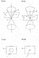
FIGS. 5A and 5B are schematic views for illustrating a principle that a locus of an irradiation position of a laser beam to a laser irradiation surface changes. -
FIGS. 6A and 6B are top views of the locus of the irradiation position of the laser beam to the laser irradiation surface. -
FIGS. 7A and 7B are schematic views for illustrating a principle of obtaining an inclination angle of an inspection tool on the basis of a change in the locus of the irradiation position of the laser beam to the laser irradiation surface. -
FIG. 8 is a sectional view depicting an example of a rolling bearing unit for wheel support having a swaging part formed by a swing forging apparatus. - An example of an embodiment of the present invention will be described with reference to
FIGS. 1 to 7B . - First, a swing forging apparatus, which is an inspection target of the example, is described with reference to
FIGS. 1 to 3 . - The swing forging apparatus can form the
swaging part 9 of the rolling bearing unit for wheel support shown inFIG. 8 . The swing forging apparatus includes abase 10, asupport column 11, aholder 12, ahead 13, a head driving means 14, and aprocessing roll 15. - The
holder 12 is fixed to an upper surface of thebase 10. Theholder 12 can hold and fix the hub main body 6 configuring the rolling bearing unit for wheel support. The axially inboard end portion of the hub main body 6 held and fixed toholder 12 faces upward. Also, at a state where the hub main body 6 is held and fixed to theholder 12, both the central axes of the hub main body 6 is held and fixed to theholder 12 coincide with each other in an upper and lower direction. - The
head 13 is arranged above theholder 12. Thehead 13 is supported by thesupport column 11 fixed to thebase 10, via the head driving means 14. At a state where thehead 13 is supported to thesupport column 11, a central axis α of thehead 13 coincides with the central axis of the holder 12 (the central axis of the hub main body 6). Thehead 13 is provided on its lower surface with a holdingconcave hole 16 having s central axis inclined relative to the central axis α of thehead 13. - The head driving means 14 includes a
spindle device 17 and acylinder 18. - The
spindle device 17 is arranged in the upper and lower direction. Thespindle device 17 can rotatively drive a spindle shaft (not shown) arranged at a radially central portion in a direct manner (without via a deceleration mechanism) by anelectric motor 19 arranged at an upper end portion of the spindle device. - The
cylinder 18 is a hydraulic cylinder and can displace thespindle device 17 relative to thesupport column 11 in the upper and lower direction. - The
head 13 is coupled and fixed to a lower end portion of the spindle shaft of thespindle device 17. At this state, thehead 13 can be rotatively driven about the central axis α by thespindle device 17 and can also be displaced in the upper and lower direction (an axial direction of the head) by thecylinder 18. - The
processing roll 15 includes ashaft part 20, ahead part 21, and apressing surface 22. Thehead part 21 is provided at a lower end portion of theshaft part 20 and has a diameter larger than theshaft part 20. Thepressing surface 22 is provided over an entire circumference of a lower surface of thehead part 21 and has a circular ring shape. - The
shaft part 20 of theprocessing roll 15 is inserted in the holdingconcave hole 16 of thehead 13. At this state, an upper end portion of theshaft part 20 is rotatably supported by athrust rolling bearing 23, and an axially intermediate portion of theshaft part 20 is rotatably supported by aradial rolling bearing 24. That is, at a state where thehead part 21 protrudes from a lower surface of thehead 13 and a central axis β of the processing roll is inclined relative to the central axis α of thehead 13 by an inclination angle θ, theprocessing roll 15 is supported to thehead 13 to be rotatable about the central axis β. - A method of forming the
swaging part 9 at the axially inboard end portion of the hub main body 6, which is a workpiece, by the swing forging apparatus configured as described above is described. - At a state where the hub main body 6 before the
swaging part 9 is formed and the other components configuring the rolling bearing unit for wheel support are assembled, the hub main body 6 is held and fixed by theholder 12, so that the central axis of the hub main body 6 is made to coincide with the central axis α of thehead 13, as shown inFIG. 2 . Meanwhile, inFIGS. 2 and3 , only the axially inboard end portion of the hub main body 6 and theinner ring 7 of the rolling bearing unit for wheel support are shown, and the other parts are not shown. - At this state, as shown in
FIG. 2 , a circumferential portion of thepressing surface 22 of theprocessing roll 15 is pressed to a circumferential portion of the axially inboard end portion of thecylindrical part 8 provided at the axially inboard end portion of the hub main body 6. At this time, the pressing force is generated by thecylinder 18. - At this state, when the
head 13 is rotatively driven about the central axis α, theprocessing roll 15 is rotated (revolved) about the central axis α of thehead 13 and is also rotated on the central axis β of the processing roll. As a result, the processing of plastically deforming thecylindrical part 8 in the radially outward direction progresses partially and continuously in the circumferential direction, so that theswaging part 9 is formed, as shown inFIG. 3 . - Subsequently, an inspection device of the swing forging apparatus of the example is described with reference to
FIGS. 4 to 7B . - The inspection device of the swing forging apparatus of the example is configured to obtain (to precisely estimate) a position of a swing center P of the
processing roll 15 and an inclination angle θ of the central axis β of theprocessing roll 15 relative to the central axis α of thehead 13, for the swing forging apparatus after completion. - The swing center P is an intersection point of the central axis α of the
head 13 and the central axis β of theprocessing roll 15. Also, the position of the swing center P is a position at a coordinate system set for the swing forging apparatus, and in this example, changes as thecylinder 18 is driven by a command from a controller (a control unit) of the swing forging apparatus. Also, the position of the swing center P is a position of a height Z from areference surface 34, which is an upper surface of thebase 10. - The inspection device of the swing forging apparatus of the example includes an
inspection tool 25, a receivingstand 26, alaser irradiation surface 27, a sensor (not shown), and a computer (not shown) having a calculator. - When inspecting the swing forging apparatus, the
inspection tool 25 is supported to thehead 13 at a state where theprocessing roll 15 is not supported thereto, with the substantially same condition as theprocessing roll 15. Theinspection tool 25 can emit a laser beam BL onto a central axis thereof (onto a central axis βA). Theinspection tool 25 includes aninspection roll part 29 and alaser generator 30. - The inspection roll
part 29 has substantially the same stiffness as theprocessing roll 15. The inspection rollpart 29 has ashaft part 20a, ahead part 21a, and a pressing surface 22a. Thehead part 21a is provided at a lower end portion of theshaft part 20a and has a diameter larger than theshaft part 20a. The pressing surface 22a is provided over an entire circumference of a lower surface of thehead part 21a and has a circular ring shape. - Meanwhile, in this example, a shape of the pressing surface 22a is different from the
pressing surface 22 of the processing roll 15 (i.e., the shape is simply a conical surface). However, when implementing the present invention, the shape of the pressing surface 22a may be made to be the same as the shape of thepressing surface 22. - The inspection roll
part 29 is supported to thehead 13 at a state where theprocessing roll 15 is not supported thereto, with the substantially same condition as theprocessing roll 15. That is, at a state where theshaft part 20a is inserted in the holdingconcave hole 16 of thehead 13, an upper end portion of theshaft part 20a of theinspection roll part 29 is rotatably supported by athrust rolling bearing 23a, and an axially intermediate portion of theshaft part 20a is rotatably supported by a radial rolling bearing 24a. - The
thrust rolling bearing 23a and the radial rolling bearing 24a have the same specifications as thethrust rolling bearing 23 and theradial rolling bearing 24 for supporting theprocessing roll 15. Therefore, therespective bearings respective bearings - The
laser generator 30 is mounted to a radially central portion of theinspection roll part 29. A tip end portion of thelaser generator 30 protrudes from a central portion of a lower surface of thehead part 21a configuring theinspection roll part 29. The laser beam BL can be emitted from the tip end portion of thelaser generator 30 onto the central axis of theinspection tool 25. Meanwhile, in this example, thelaser generator 30 has a battery for power supply. - The receiving
stand 26 is held and fixed by the holder 12 (not shown inFIG. 4 ; refer toFIG. 1 ) with being arranged below thehead 13 when inspecting the swing forging apparatus. The receivingstand 26 is formed to have a bottomed cylindrical shape by a metal material such as a steel material. The receivingstand 26 has acylindrical part 31 and abottom plate part 32. - A central axis of the
cylindrical part 31 coincides with the central axis α of thehead 13. Thebottom plate part 32 blocks a lower end opening of thecylindrical part 31. The pressing surface 22a of theinspection tool 25 can be pressed to an upper end portion of thecylindrical part 31, irrespective of a rotational position of thehead 13. That is, when thehead 13 is rotated about the central axis α thereof with the pressing surface 22a of theinspection tool 25 being pressed to the upper end portion of thecylindrical part 31, theinspection tool 25 can be rotated (revolved) about the central axis α of thehead 13 and can also be rotated on the central axis βA thereof. - The
laser irradiation surface 27 is arranged below thehead 13 and the laser beam BL is irradiated thereto when inspecting the swing forging apparatus. In this example, thelaser irradiation surface 27 is provided on an upper surface of an elevating table 33 provided in the receivingstand 26. Thelaser irradiation surface 27 is a planar surface perpendicular to the central axis α of thehead 13. - The elevating table 33 can be lifted up and down by an electrically operated elevator device (not shown) provided in the receiving
stand 26. That is, when the elevating table 33 is lifted up and down, a relative position between thelaser irradiation surface 27 and the head 13 (the inspection tool 25) can be changed in an axial direction of thehead 13. In other words, thelaser irradiation surface 27 can change the height Z from thereference surface 34. - When inspecting the swing forging apparatus, the sensor is provided in the receiving
stand 26, and can detect an irradiation position of the laser beam BL to thelaser irradiation surface 27. - In this example, the sensor is a planar image sensor such as a CCD, a CMOS or the like, and can acquire an irradiation position of the laser beam BL to the
laser irradiation surface 27 by an X-Y coordinate on thelaser irradiation surface 27. - The computer has a function of obtaining a position of a swing center PA of the
inspection tool 25 and an inclination angle θA of a central axis βA of theinspection roll part 29 relative to the central axis α of thehead 13 by using the detection signal of the sensor (a signal indicative of the irradiation position of the laser beam BL to the laser irradiation surface 27). This function will be specifically described later. - In the meantime, the swing center PA is an intersection point of the central axis α of the
head 13 and the central axis βA of theinspection tool 25. Also, the position of the swing center PA is a position at the coordinate system set to the swing forging apparatus, and in this example, is position of the height Z from thereference surface 34. - A method of inspecting the swing forging apparatus with the inspection device configured as described above is described.
- As shown in
FIG. 4 , the pressing surface 22a of theinspection tool 25 is pressed to the upper end portion of thecylindrical part 31 configuring the receivingstand 26. At this time, the pressing force is generated by thecylinder 18. Thereby, the load, which is substantially the same as the load to be applied to theprocessing roll 15 upon the processing of theswaging part 9, is applied to theinspection tool 25, so that therespective rolling bearings 23a, 24a are elastically deformed. Thereby, the position of the swing center PA and the inclination angle θA of theinspection tool 25 are changed to be the same as the position of the swing center P and the inclination angle θ of theprocessing roll 15 upon the processing of theswaging part 9. At this state, thehead 13 is rotatively driven about the central axis α thereof, so that while theinspection tool 25 is revolved (and rotated), the laser beam BL is emitted from thelaser generator 30 and the laser beam BL is irradiated to thelaser irradiation surface 27. - As the
inspection tool 25 is revolved as described above, the laser beam BL forms a conical shape as shown inFIGS. 5A and 5B . For this reason, a locus λ of the laser beam BL irradiated to thelaser irradiation surface 27 forms a circle as shown inFIGS. 6A and7A or becomes a point as shown inFIGS. 6B and7B by changing the height Z of thelaser irradiation surface 27. A position (height Z) of the point is the position of the swing center PA of theinspection tool 25. - Therefore, in this example, the computer is configured to obtain the position of the swing center PA of the
inspection tool 25, which is the height Z at which the locus λ of the irradiation position becomes a point, on the basis of the detection signal of the sensor by changing the height Z of the laser irradiation surface 27 (by changing the relative position between thelaser irradiation surface 27 and theinspection tool 25 in the axial direction of the head 13). - In the meantime, when implementing this example, the locus λ may not be a complete point due to component precision and the like even if the height Z of the
laser irradiation surface 27 is changed. In this case, the height Z at which a radius of the locus λ is smallest is obtained as the position of the swing center PA. - Also, in this example, the computer is configured to change the height Z of the laser irradiation surface 27 (in any of the upward and downward directions) by ΔL from the position at which the locus λ of the laser beam BL irradiated to the
laser irradiation surface 27 becomes a point. Thereby, for example, as shown inFIGS. 7A and 7B , the locus λ of the laser beam BL irradiated to thelaser irradiation surface 27 becomes a circle having a radius ΔR. The computer is configured to obtain the radius ΔR on the basis of the detection signal of the sensor and to calculate an inclination angle of theinspection tool 25 on the basis of a geometrical relationship {tanθA=ΔR/ΔL→θA=tan-1(ΔR/ΔL)} shown inFIGS. 7A and 7B . In the meantime, when implementing the present invention, the inclination angle θA may also be calculated by changing the height of thelaser irradiation surface 27 by the variation ΔL from the position at which the locus λ becomes a circle and using a variation ΔR of the radius of the locus λ resulting from the change, based on the equation {θA=tan-1(ΔR/ΔL)}. - Meanwhile, in this example, when performing the inspection as described above, the
inspection tool 25 is supported to thehead 13 at the state where theprocessing roll 15 is not supported thereto, with the substantially same condition as theprocessing roll 15. Also, theinspection tool 25 is applied with the load, which is substantially the same as the load to be applied to theprocessing roll 15 upon the processing of theswaging part 9. - For this reason, under condition that the
head 13 is located at the same axial position, the position of the swing center PA of theinspection tool 25 obtained in the above inspection and the position of the swing center P of theprocessing roll 15 upon the processing of theswaging part 9 coincide with each other with precision. Therefore, under condition that thehead 13 is located at the same axial position, the position of the swing center PA of theinspection tool 25 obtained as described above can be precisely estimated as the position of the swing center P of theprocessing roll 15 upon the processing of theswaging part 9. - In the meantime, when the
cylinder 18 is driven by a command from the controller of the swing forging apparatus, the position of the swing center P of theprocessing roll 15 is moved in the axial direction of thehead 13. Here, when the position of the swing center P estimated as described above is stored in the controller (as a set with the axial position of the head 13), even though the swing center P is thereafter moved in the axial direction of thehead 13, the controller can correctly perceive the position of the swing center P after the movement. - Likewise, the inclination angle θA of the
inspection tool 25 calculated as described above precisely coincides with the inclination angle θ of theprocessing roll 15 upon the processing of theswaging part 9. Therefore, the inclination angle θA of theinspection tool 25 calculated as described above can be precisely estimated as the inclination angle θ of theprocessing roll 15 upon the processing of theswaging part 9. - In the meantime, the position, which is estimated as described above (which the controller is enabled to recognize), of the swing center P of the
processing roll 15 upon the processing of theswaging part 9 can be used for management for appropriately forming theswaging part 9. For example, when forming theswaging part 9 by designing the hub main body 6 on the basis of the position of the swing center P of theprocessing roll 15, the processing may be ended at a point of time at which the position of the swing center P of theprocessing roll 15 reaches a predetermined position on the central axis of the hub main body 6. In this case, it is possible to appropriately form theswaging part 9. - Also, the inclination angle θ, which is estimated as described above, of the
processing roll 15 upon the processing of theswaging part 9 can be used for management for appropriately forming theswaging part 9. That is, even though the inclination angle θ of the processing roll is different from a designed inclination angle, when a difference therebetween is within a preset acceptable range, it is possible to appropriately form theswaging part 9. In contrast, when the difference is beyond the acceptable range, it is not possible to appropriately form theswaging part 9. Like this, when the difference is beyond the acceptable range, it is possible to appropriately form theswaging part 9 by correcting the difference to be within the acceptable range, for example, by replacing a component of the swing forging apparatus. - Also, in this example, the inspection of the swing forging apparatus as described above may be performed without pressing the pressing surface 22a of the
inspection tool 25 to the upper end portion of the cylindrical part 31 (without applying the load to the inspection tool 25). In this case, the position of the swing center PA and the inclination angle θA of theinspection tool 25 obtained by the computer can be precisely estimated as the position of the swing center P and the inclination angle θ of theprocessing roll 15 at a state where theswaging part 9 is not processed. - In the meantime, the position of the swing center P and the inclination angle θ, which are estimated as described above, of the
processing roll 15 at a state where theswaging part 9 is not processed can be used to check whether the swing forging apparatus after completion has been manufactured as designed. In addition, when there is a plurality of manufacturing processes (lines) of bearing units including the swing forging apparatus as described above and bearing units having the same model number are manufactured in the processes, it is possible to manufacture the bearing units having the same model number of which a deviation of qualities is sufficiently suppressed by measuring the position of the swing center and the inclination angle of the swing forging apparatus included in each process and adjusting a difference therebetween. - The subject application is based on Japanese Patent Application No.
2016-137710 filed on July 12, 2016 - The present invention is not limited to the swing forging apparatus shown in
FIGS. 1 to 3 , and may be implemented for a variety of swing forging apparatuses including the swing forging apparatuses disclosed inPatent Documents 1 to 3. - Also, upon the implementation of the present invention, when inspecting the swing forging apparatus while applying a predetermined load to the inspection tool, the predetermined load is not limited to the load, which is to be applied to the processing roll when processing a workpiece by the processing roll, and may be a light load for suppressing the backlash of the inspection tool with respect to the head.
- 1: outer ring, 2: hub, 3a, 3b: outer race, 4a, 4b: inner race, 5: rolling element, 6: hub main body, 7: inner ring, 8: cylindrical part, 9: swaging part, 10: base, 11: support column, 12: holder, 13: head, 14: head driving means, 15: processing roll, 16: holding concave hole, 17: spindle device, 18: cylinder, 19: electric motor, 20, 20a: shaft part, 21, 21a: head part, 22, 22a: pressing surface, 23, 23a: thrust rolling bearing, 24, 24a: radial rolling bearing, 25: inspection tool, 26: receiving stand, 27: laser irradiation surface, 29: inspection roll part, 30: laser generator, 31: cylindrical part, 32: bottom plate part, 33: elevating table, 34: reference surface
Claims (11)
- An inspection device of a swing forging apparatus,
wherein the swing forging apparatus comprises:a head configured to be rotatively driven about a central axis of the head,a processing roll supported to the head so that the processing roll is rotatable about a central axis of the processing roll at a state where the central axis of the processing roll is inclined relative to the central axis of the head,wherein the inspection device of the swing forging apparatus comprises an inspection tool and a laser irradiation surface,
wherein when inspecting the swing forging apparatus, the inspection tool is supported to the head to which the processing roll is not supported, with a substantially same condition as the processing roll, and the inspection tool has a function of emitting a laser beam onto a central axis of the inspection tool, and
wherein when inspecting the swing forging apparatus, the laser irradiation surface is arranged so that a relative position of the laser irradiation surface to the head in an axial direction of the head can be changed and the laser beam can be irradiated to the laser irradiation surface. - The inspection device of the swing forging apparatus according to claim 1 comprising a sensor,
wherein when inspecting the swing forging apparatus, the sensor is arranged to detect an irradiation position of the laser beam to the laser irradiation surface. - The inspection device of the swing forging apparatus according to claim 2 comprising a calculator,
wherein when inspecting the swing forging apparatus, at a state where the head is rotatively driven about a central axis of the head and a laser beam emitted from the inspection tool onto the central axis of the inspection tool is irradiated to the laser irradiation surface, the calculator has functions of changing a radius of a locus of an irradiation position of the laser beam to the laser irradiation surface by changing a relative position between the head and the laser irradiation surface in the axial direction of the head, and obtaining a position of the locus having a minimum radius at a coordinate system set for the swing forging apparatus on a basis of a detection signal of the sensor when the radius becomes smallest. - The inspection device of the swing forging apparatus according to claim 3,
wherein the position of the locus having the minimum radius is estimated as a position of a swing center of the processing roll at a state where the processing roll is supported to the head. - The inspection device of the swing forging apparatus according to any one of claims 2 to 4 comprising a calculator,
wherein when inspecting the swing forging apparatus, at a state where the head is rotatively driven about a central axis of the head and a laser beam emitted from the inspection tool onto the central axis of the inspection tool is irradiated to the laser irradiation surface, and when a locus of an irradiation position of the laser beam to the laser irradiation surface is changed by changing a relative position between the head and the laser irradiation surface in the axial direction of the head, the calculator has functions of obtaining a variation ΔR in a radius of the locus of the irradiation position on a basis of a detection signal of the sensor when the relative position is changed by a variation ΔL, and obtaining an inclination angle of the central axis of the inspection tool relative to the central axis of the head by using the respective variations ΔL and ΔR. - The inspection device of the swing forging apparatus according to claim 5,
wherein the inclination angle of the central axis of the inspection tool relative to the central axis of the head is estimated as an inclination angle of the central axis of the processing roll relative to the central axis of the head at a state where the processing roll is supported to the head. - An inspection tool of a swing forging apparatus,
wherein the swing forging apparatus comprises:a head configured to be rotatively driven about a central axis of the head, anda processing roll supported to the head so that the processing roll is rotatable about a central axis of the processing roll at a state where the central axis of the processing roll is inclined relative to the central axis of the head,wherein when inspecting the swing forging apparatus, the inspection tool is supported to the head to which the processing roll is not supported, with a substantially same condition as the processing roll, and the inspection tool has a function of emitting a laser beam onto a central axis of the inspection tool. - An inspection method of a swing forging apparatus,
wherein when inspecting the swing forging apparatus by using the inspection device of the swing forging apparatus according to any one of claims 1 to 4, at a state where the head is rotatively driven about a central axis of the head and a laser beam emitted from the inspection tool onto a central axis of the inspection tool is irradiated to the laser irradiation surface, inspection method comprises:changing a radius of a locus of an irradiation position of the laser beam to the laser irradiation surface to minimize the locus by changing a relative position between the head and the laser irradiation surface in the axial direction of the head, andobtaining a position of the locus having a minimum radius at a coordinate system set for the swing forging apparatus. - An inspection method of a swing forging apparatus,
wherein when inspecting the swing forging apparatus by using the inspection device of the swing forging apparatus according to any one of claims 1 to 6, at a state where the head is rotatively driven about a central axis of the head and a laser beam emitted from the inspection tool onto a central axis of the inspection tool is irradiated to the laser irradiation surface, the inspection method comprises:obtaining a variation ΔR in a radius of the locus of the irradiation position when the relative position is changed by a variation ΔL by changing a locus of an irradiation position of the laser beam to the laser irradiation surface by changing a relative position between the head and the laser irradiation surface in the axial direction of the head, andobtaining an inclination angle of the central axis of the inspection tool relative to the central axis of the head by using the variations ΔL and ΔR. - A manufacturing apparatus of a bearing unit,
wherein the bearing unit comprises:an outer ring having double rows of outer races formed on an inner peripheral surface of the outer ring,a hub having double rows of inner races formed on an outer peripheral surface of the hub, anda plurality of rolling elements provided between the double rows of outer races and the double rows of inner races,wherein the hub is configured by coupling a hub main body, which has the inner race directly formed at one axial side of an outer peripheral surface of the hub main body, to an inner ring, which has the inner race directly formed on at the other axial side of an outer peripheral surface of the inner ring,
wherein the inner ring is externally fitted to the other axial side of the hub main body,
wherein an axial end face of the inner ring is pressed by a swaging part formed by plastically deforming a cylindrical part, which is provided at the other axial end portion of the hub main body, in a radially outward direction,
wherein the manufacturing apparatus comprises a swing forging apparatus inspected by the inspection device of the swing forging apparatus according to any one of claims 1 to 6,
wherein the swing forging apparatus is configured to press the processing roll to a circumferential portion of the other axial end portion of the cylindrical part at a state where a central axis of the hub main body coincides with the central axis of the head,
wherein at this state, the swing forging apparatus is configured to revolve the processing roll about the central axis of the head and to rotate the processing roll about the central axis of the processing roll by rotatively driving the head about the central axis of the head, and
wherein the swing forging apparatus is configured to form the swaging part by plastically deforming the cylindrical part of the hub main body in one radial direction. - A manufacturing method of a bearing unit,
wherein the bearing unit comprises:an outer ring having double rows of outer races formed on an inner peripheral surface of the outer ring,
a hub having double rows of inner races formed on an outer peripheral surface of the hub, anda plurality of rolling elements provided between the double rows of outer races and the double rows of inner races,wherein the hub is configured by coupling a hub main body, which has the inner race directly formed at one axial side of an outer peripheral surface of the hub main body, to an inner ring, which has the inner race directly formed on at the other axial side of an outer peripheral surface of the inner ring,
wherein the inner ring is externally fitted to the other axial side of the hub main body,
wherein an axial end face of the inner ring is pressed by a swaging part formed by plastically deforming a cylindrical part, which is provided at the other axial end portion of the hub main body, in a radially outward direction,
wherein in the manufacturing method, a swing forging apparatus, which is inspected by the inspection device of the swing forging apparatus according to any one of claims 1 to 6, is used, and
wherein the manufacturing method comprises:pressing the processing roll to a circumferential portion of the other axial end portion of the cylindrical part at a state where a central axis of the hub main body coincides with the central axis of the head,at this state, revolving the processing roll about the central axis of the head and rotating the processing roll about the central axis of the processing roll by rotatively driving the head about the central axis of the head, andforming the swaging part by plastically deforming the cylindrical part of the hub main body in one radial direction.
Applications Claiming Priority (2)
| Application Number | Priority Date | Filing Date | Title |
|---|---|---|---|
| JP2016137710 | 2016-07-12 | ||
| PCT/JP2017/025278 WO2018012500A1 (en) | 2016-07-12 | 2017-07-11 | Rotary forge device testing device, testing tool, testing method, bearing unit manufacturing device, and bearing unit manufacturing method |
Publications (2)
| Publication Number | Publication Date |
|---|---|
| EP3450908A1 true EP3450908A1 (en) | 2019-03-06 |
| EP3450908A4 EP3450908A4 (en) | 2019-05-08 |
Family
ID=60953048
Family Applications (1)
| Application Number | Title | Priority Date | Filing Date |
|---|---|---|---|
| EP17827627.5A Withdrawn EP3450908A4 (en) | 2016-07-12 | 2017-07-11 | Rotary forge device testing device, testing tool, testing method, bearing unit manufacturing device, and bearing unit manufacturing method |
Country Status (6)
| Country | Link |
|---|---|
| US (2) | US10399141B2 (en) |
| EP (1) | EP3450908A4 (en) |
| JP (2) | JP6332572B1 (en) |
| KR (1) | KR20190008881A (en) |
| CN (1) | CN109416241A (en) |
| WO (1) | WO2018012500A1 (en) |
Families Citing this family (9)
| Publication number | Priority date | Publication date | Assignee | Title |
|---|---|---|---|---|
| CN111971133B (en) * | 2018-02-13 | 2022-07-19 | 日本精工株式会社 | Dynamic load measuring and correcting method for rocking forging device, dynamic load measuring device, hub unit bearing, and method for manufacturing vehicle |
| CN108692940B (en) * | 2018-06-12 | 2023-11-24 | 华南理工大学 | A transmission shaft assembly for sequential testing of flexible thin-walled bearings |
| CN109454412A (en) * | 2018-12-28 | 2019-03-12 | 同共(湖北)精密成形有限公司 | A kind of processing method of bearing race |
| CN113631294B (en) | 2019-04-10 | 2025-01-03 | 日本精工株式会社 | Manufacturing method of riveted assembly, manufacturing method of hub unit bearing, riveting device, riveted assembly, and manufacturing method of vehicle |
| EP3892397B1 (en) | 2019-04-10 | 2025-07-30 | NSK Ltd. | Method for manufacturing hub unit bearing, and method for manufacturing vehicle |
| CN111421300A (en) * | 2019-11-07 | 2020-07-17 | 襄阳汽车轴承股份有限公司 | Narrow series thin-wall conical bearing inner ring or outer ring blank forming and turning process |
| CN113210558B (en) * | 2021-05-26 | 2025-03-28 | 浙江宏茂重工有限公司 | A new forging device |
| CN113600736A (en) * | 2021-06-28 | 2021-11-05 | 中国铝业股份有限公司 | Swing rolling processing device and control method of swing rolling processing device |
| DE102021127188B4 (en) * | 2021-10-20 | 2023-08-17 | Schaeffler Technologies AG & Co. KG | Device and method for producing a face gear |
Family Cites Families (11)
| Publication number | Priority date | Publication date | Assignee | Title |
|---|---|---|---|---|
| US4566202A (en) * | 1983-12-06 | 1986-01-28 | Hamar M R | Laser apparatus for effectively projecting the axis of rotation of a rotating tool holder |
| CH666857A5 (en) * | 1984-11-27 | 1988-08-31 | Heinrich Schmid Maschinen Und | SWASH PRESS. |
| JPH06142719A (en) * | 1992-11-09 | 1994-05-24 | Sumitomo Metal Ind Ltd | Centering measuring instrument for piercing mill |
| US5761994A (en) * | 1995-02-02 | 1998-06-09 | Aida Engineering Ltd. | Multi-slide mechanical press with phase difference |
| JP3622458B2 (en) * | 1997-08-28 | 2005-02-23 | 日本精工株式会社 | Rolling bearing unit for wheel support |
| EP0854303B1 (en) | 1997-01-17 | 2003-10-29 | Nsk Ltd | Rolling bearing unit for supporting vehicle wheel |
| JPH11188419A (en) * | 1997-12-26 | 1999-07-13 | Ykk Corp | Extruder alignment method |
| JP5822074B2 (en) | 2012-01-30 | 2015-11-24 | トヨタ自動車株式会社 | Swing forging device |
| JP5835068B2 (en) | 2012-04-04 | 2015-12-24 | 株式会社デンソー | Swing forging device |
| JP6237100B2 (en) * | 2013-10-17 | 2017-11-29 | 日本精工株式会社 | Manufacturing method of wheel bearing rolling bearing unit |
| CN104942196A (en) * | 2015-07-01 | 2015-09-30 | 吉林圆方机械集团有限公司 | Forging and pressing equipment |
-
2017
- 2017-07-11 KR KR1020187036098A patent/KR20190008881A/en not_active Ceased
- 2017-07-11 US US15/760,708 patent/US10399141B2/en active Active
- 2017-07-11 CN CN201780038963.2A patent/CN109416241A/en active Pending
- 2017-07-11 JP JP2017559727A patent/JP6332572B1/en active Active
- 2017-07-11 WO PCT/JP2017/025278 patent/WO2018012500A1/en not_active Ceased
- 2017-07-11 EP EP17827627.5A patent/EP3450908A4/en not_active Withdrawn
-
2018
- 2018-04-19 JP JP2018080281A patent/JP2018149600A/en active Pending
-
2019
- 2019-04-16 US US16/385,489 patent/US11077485B2/en active Active
Also Published As
| Publication number | Publication date |
|---|---|
| US11077485B2 (en) | 2021-08-03 |
| JP2018149600A (en) | 2018-09-27 |
| JP6332572B1 (en) | 2018-05-30 |
| US20190240722A1 (en) | 2019-08-08 |
| EP3450908A4 (en) | 2019-05-08 |
| WO2018012500A1 (en) | 2018-01-18 |
| US10399141B2 (en) | 2019-09-03 |
| CN109416241A (en) | 2019-03-01 |
| KR20190008881A (en) | 2019-01-25 |
| JPWO2018012500A1 (en) | 2018-07-19 |
| US20180257129A1 (en) | 2018-09-13 |
Similar Documents
| Publication | Publication Date | Title |
|---|---|---|
| US11077485B2 (en) | Rotary forge device testing device, testing tool, testing method, bearing unit manufacturing device, bearing unit manufacturing method, and vehicle manufacturing method | |
| JP7188305B2 (en) | Load measuring method for orbital forging device, load measuring device, method for calibrating orbital forging device, method for manufacturing hub unit bearing, method for manufacturing vehicle | |
| KR20140077605A (en) | Apparatus for measuring gap of roll bearing in continuous casting machine | |
| US11959515B2 (en) | Conveying system, rotary forging method, rotary forging apparatus, method for manufacturing bearing, method for manufacturing vehicle, and method for manufacturing mechanical device | |
| JP6685683B2 (en) | Method for manufacturing outer joint member of constant velocity universal joint and ultrasonic flaw detection method for welded portion | |
| US9238289B2 (en) | Grinding method of grinding roller workpiece and grinding apparatus for grinding roller workpiece | |
| US20220049955A1 (en) | Method for acquiring contact angle of angular contact ball bearing and method for manufacturing wheel bearing device | |
| JPWO2022085744A5 (en) | ||
| JP6558516B1 (en) | Centering method of swing caulking device, manufacturing method of swing caulking device, manufacturing method of hub unit bearing, manufacturing method of vehicle, centering device of swing caulking device, swing caulking system | |
| JP2015194248A (en) | Manufacturing method of outside joint member of constant velocity universal joint, and outside joint member, shank member, and cup member | |
| JP2019116917A (en) | Method of manufacturing hub unit bearing | |
| JP2017020561A (en) | Method for manufacturing outer joint member of constant velocity universal joint and ultrasonic flaw detection inspection method for welded part | |
| JP6551634B1 (en) | Hub unit bearing manufacturing method and manufacturing apparatus, vehicle manufacturing method | |
| JP2021177133A (en) | Preload measurement method of bearing device and manufacture method of bearing device | |
| WO2017153398A1 (en) | A method and device for determining shim thickness | |
| JP5666321B2 (en) | Spindle structure and tire testing machine equipped with the same | |
| JP2007319865A (en) | Manufacturing method and manufacturing apparatus for rolling bearing unit for supporting wheel | |
| CN111212704A (en) | Honing machines and honing machine applications |
Legal Events
| Date | Code | Title | Description |
|---|---|---|---|
| STAA | Information on the status of an ep patent application or granted ep patent |
Free format text: STATUS: THE INTERNATIONAL PUBLICATION HAS BEEN MADE |
|
| PUAI | Public reference made under article 153(3) epc to a published international application that has entered the european phase |
Free format text: ORIGINAL CODE: 0009012 |
|
| STAA | Information on the status of an ep patent application or granted ep patent |
Free format text: STATUS: REQUEST FOR EXAMINATION WAS MADE |
|
| 17P | Request for examination filed |
Effective date: 20180905 |
|
| AK | Designated contracting states |
Kind code of ref document: A1 Designated state(s): AL AT BE BG CH CY CZ DE DK EE ES FI FR GB GR HR HU IE IS IT LI LT LU LV MC MK MT NL NO PL PT RO RS SE SI SK SM TR |
|
| AX | Request for extension of the european patent |
Extension state: BA ME |
|
| A4 | Supplementary search report drawn up and despatched |
Effective date: 20190405 |
|
| RIC1 | Information provided on ipc code assigned before grant |
Ipc: B21J 9/20 20060101ALI20190401BHEP Ipc: B60B 27/00 20060101ALI20190401BHEP Ipc: G01B 11/00 20060101AFI20190401BHEP Ipc: B21J 9/06 20060101ALI20190401BHEP Ipc: G01B 11/27 20060101ALI20190401BHEP Ipc: G01B 11/26 20060101ALI20190401BHEP Ipc: B21J 9/02 20060101ALI20190401BHEP |
|
| DAV | Request for validation of the european patent (deleted) | ||
| DAX | Request for extension of the european patent (deleted) | ||
| STAA | Information on the status of an ep patent application or granted ep patent |
Free format text: STATUS: EXAMINATION IS IN PROGRESS |
|
| 17Q | First examination report despatched |
Effective date: 20200304 |
|
| STAA | Information on the status of an ep patent application or granted ep patent |
Free format text: STATUS: THE APPLICATION IS DEEMED TO BE WITHDRAWN |
|
| 18D | Application deemed to be withdrawn |
Effective date: 20200715 |