EP3450793A1 - Brake disk and method for manufacturing the same - Google Patents
Brake disk and method for manufacturing the same Download PDFInfo
- Publication number
- EP3450793A1 EP3450793A1 EP17206413.1A EP17206413A EP3450793A1 EP 3450793 A1 EP3450793 A1 EP 3450793A1 EP 17206413 A EP17206413 A EP 17206413A EP 3450793 A1 EP3450793 A1 EP 3450793A1
- Authority
- EP
- European Patent Office
- Prior art keywords
- brake disk
- friction surface
- eutectic cells
- per unit
- unit area
- Prior art date
- Legal status (The legal status is an assumption and is not a legal conclusion. Google has not performed a legal analysis and makes no representation as to the accuracy of the status listed.)
- Granted
Links
Images


Classifications
-
- F—MECHANICAL ENGINEERING; LIGHTING; HEATING; WEAPONS; BLASTING
- F16—ENGINEERING ELEMENTS AND UNITS; GENERAL MEASURES FOR PRODUCING AND MAINTAINING EFFECTIVE FUNCTIONING OF MACHINES OR INSTALLATIONS; THERMAL INSULATION IN GENERAL
- F16D—COUPLINGS FOR TRANSMITTING ROTATION; CLUTCHES; BRAKES
- F16D65/00—Parts or details
- F16D65/02—Braking members; Mounting thereof
-
- F—MECHANICAL ENGINEERING; LIGHTING; HEATING; WEAPONS; BLASTING
- F16—ENGINEERING ELEMENTS AND UNITS; GENERAL MEASURES FOR PRODUCING AND MAINTAINING EFFECTIVE FUNCTIONING OF MACHINES OR INSTALLATIONS; THERMAL INSULATION IN GENERAL
- F16D—COUPLINGS FOR TRANSMITTING ROTATION; CLUTCHES; BRAKES
- F16D65/00—Parts or details
- F16D65/02—Braking members; Mounting thereof
- F16D65/12—Discs; Drums for disc brakes
- F16D65/127—Discs; Drums for disc brakes characterised by properties of the disc surface; Discs lined with friction material
-
- F—MECHANICAL ENGINEERING; LIGHTING; HEATING; WEAPONS; BLASTING
- F16—ENGINEERING ELEMENTS AND UNITS; GENERAL MEASURES FOR PRODUCING AND MAINTAINING EFFECTIVE FUNCTIONING OF MACHINES OR INSTALLATIONS; THERMAL INSULATION IN GENERAL
- F16D—COUPLINGS FOR TRANSMITTING ROTATION; CLUTCHES; BRAKES
- F16D65/00—Parts or details
- F16D65/02—Braking members; Mounting thereof
- F16D65/12—Discs; Drums for disc brakes
- F16D65/125—Discs; Drums for disc brakes characterised by the material used for the disc body
-
- B—PERFORMING OPERATIONS; TRANSPORTING
- B22—CASTING; POWDER METALLURGY
- B22D—CASTING OF METALS; CASTING OF OTHER SUBSTANCES BY THE SAME PROCESSES OR DEVICES
- B22D15/00—Casting using a mould or core of which a part significant to the process is of high thermal conductivity, e.g. chill casting; Moulds or accessories specially adapted therefor
-
- B—PERFORMING OPERATIONS; TRANSPORTING
- B24—GRINDING; POLISHING
- B24B—MACHINES, DEVICES, OR PROCESSES FOR GRINDING OR POLISHING; DRESSING OR CONDITIONING OF ABRADING SURFACES; FEEDING OF GRINDING, POLISHING, OR LAPPING AGENTS
- B24B19/00—Single-purpose machines or devices for particular grinding operations not covered by any other main group
-
- B—PERFORMING OPERATIONS; TRANSPORTING
- B24—GRINDING; POLISHING
- B24B—MACHINES, DEVICES, OR PROCESSES FOR GRINDING OR POLISHING; DRESSING OR CONDITIONING OF ABRADING SURFACES; FEEDING OF GRINDING, POLISHING, OR LAPPING AGENTS
- B24B7/00—Machines or devices designed for grinding plane surfaces on work, including polishing plane glass surfaces; Accessories therefor
- B24B7/10—Single-purpose machines or devices
- B24B7/16—Single-purpose machines or devices for grinding end-faces, e.g. of gauges, rollers, nuts, piston rings
- B24B7/17—Single-purpose machines or devices for grinding end-faces, e.g. of gauges, rollers, nuts, piston rings for simultaneously grinding opposite and parallel end faces, e.g. double disc grinders
-
- F—MECHANICAL ENGINEERING; LIGHTING; HEATING; WEAPONS; BLASTING
- F16—ENGINEERING ELEMENTS AND UNITS; GENERAL MEASURES FOR PRODUCING AND MAINTAINING EFFECTIVE FUNCTIONING OF MACHINES OR INSTALLATIONS; THERMAL INSULATION IN GENERAL
- F16D—COUPLINGS FOR TRANSMITTING ROTATION; CLUTCHES; BRAKES
- F16D65/00—Parts or details
- F16D65/0006—Noise or vibration control
-
- F—MECHANICAL ENGINEERING; LIGHTING; HEATING; WEAPONS; BLASTING
- F16—ENGINEERING ELEMENTS AND UNITS; GENERAL MEASURES FOR PRODUCING AND MAINTAINING EFFECTIVE FUNCTIONING OF MACHINES OR INSTALLATIONS; THERMAL INSULATION IN GENERAL
- F16D—COUPLINGS FOR TRANSMITTING ROTATION; CLUTCHES; BRAKES
- F16D65/00—Parts or details
- F16D65/02—Braking members; Mounting thereof
- F16D65/12—Discs; Drums for disc brakes
-
- F—MECHANICAL ENGINEERING; LIGHTING; HEATING; WEAPONS; BLASTING
- F16—ENGINEERING ELEMENTS AND UNITS; GENERAL MEASURES FOR PRODUCING AND MAINTAINING EFFECTIVE FUNCTIONING OF MACHINES OR INSTALLATIONS; THERMAL INSULATION IN GENERAL
- F16D—COUPLINGS FOR TRANSMITTING ROTATION; CLUTCHES; BRAKES
- F16D65/00—Parts or details
- F16D65/02—Braking members; Mounting thereof
- F16D2065/13—Parts or details of discs or drums
- F16D2065/1304—Structure
- F16D2065/1312—Structure circumferentially segmented
-
- F—MECHANICAL ENGINEERING; LIGHTING; HEATING; WEAPONS; BLASTING
- F16—ENGINEERING ELEMENTS AND UNITS; GENERAL MEASURES FOR PRODUCING AND MAINTAINING EFFECTIVE FUNCTIONING OF MACHINES OR INSTALLATIONS; THERMAL INSULATION IN GENERAL
- F16D—COUPLINGS FOR TRANSMITTING ROTATION; CLUTCHES; BRAKES
- F16D65/00—Parts or details
- F16D65/02—Braking members; Mounting thereof
- F16D2065/13—Parts or details of discs or drums
- F16D2065/1304—Structure
- F16D2065/1316—Structure radially segmented
-
- F—MECHANICAL ENGINEERING; LIGHTING; HEATING; WEAPONS; BLASTING
- F16—ENGINEERING ELEMENTS AND UNITS; GENERAL MEASURES FOR PRODUCING AND MAINTAINING EFFECTIVE FUNCTIONING OF MACHINES OR INSTALLATIONS; THERMAL INSULATION IN GENERAL
- F16D—COUPLINGS FOR TRANSMITTING ROTATION; CLUTCHES; BRAKES
- F16D2200/00—Materials; Production methods therefor
- F16D2200/0004—Materials; Production methods therefor metallic
- F16D2200/0008—Ferro
- F16D2200/0013—Cast iron
-
- F—MECHANICAL ENGINEERING; LIGHTING; HEATING; WEAPONS; BLASTING
- F16—ENGINEERING ELEMENTS AND UNITS; GENERAL MEASURES FOR PRODUCING AND MAINTAINING EFFECTIVE FUNCTIONING OF MACHINES OR INSTALLATIONS; THERMAL INSULATION IN GENERAL
- F16D—COUPLINGS FOR TRANSMITTING ROTATION; CLUTCHES; BRAKES
- F16D2250/00—Manufacturing; Assembly
- F16D2250/0007—Casting
-
- F—MECHANICAL ENGINEERING; LIGHTING; HEATING; WEAPONS; BLASTING
- F16—ENGINEERING ELEMENTS AND UNITS; GENERAL MEASURES FOR PRODUCING AND MAINTAINING EFFECTIVE FUNCTIONING OF MACHINES OR INSTALLATIONS; THERMAL INSULATION IN GENERAL
- F16D—COUPLINGS FOR TRANSMITTING ROTATION; CLUTCHES; BRAKES
- F16D2250/00—Manufacturing; Assembly
- F16D2250/003—Chip removing
Definitions
- the present invention relates to a brake disk including a friction surface formed of cast ironand a method for manufacturing the same.
- FIG. 1 illustrates a vibration phenomenon of a brake torque during braking, which may result in the judder phenomenon.
- a maximum brake torque vibration is defined as a height difference between an uppermost end and a lowermost end of a section near a maximum point of the brake torque, as the brake torque repeatedly increases and decreases.
- a maximum BTV increases, the magnitude of vibration transferred to the passenger may increase, and the judder phenomenon may become stronger.
- the maximum BTV may be reduced to prevent or reduce the judder phenomenon.
- factors generally considered to reduce the maximum BTV include the shape, the thermal capacity, and the hardness deviation of a brake disk, whether the brake disk is corroded or not, a material of a friction material of the brake disk, and the like.
- the maximum BTV greatly may vary.
- the present invention provides a brake disk which may reduce a judder phenomenon by a high BTV, and a method for manufacturing the same.
- a brake disk including a friction surface formed of cast iron.
- the friction surface of the brake disk may include a plurality of sections in a circumferential direction, and an average of numbers per unit area of eutectic cells formed on surfaces of the sections may not be greater than about 300 ea/cm 2 .
- eutectic cell refers to a solidified particle or spherical or near spherical structure that may be formed in a cast iron or iron-carbon material.
- a typical eutectic cell may have a size (e.g., diameter or longest cross-section) greater than about 580 ⁇ m, greater than about 590 ⁇ m, greater than about 600 ⁇ m, greater than about 650 ⁇ m or greater than about 700 ⁇ m.
- a eutectic cell may have a size (e.g., diameter or longest cross-section) of less than about 10,000 ⁇ m, less than about 5,000 ⁇ m or less than about 3,000 ⁇ m.
- a deviation or difference of numbers per unit area of the eutectic cells formed in the plurality of sections may be not greater than 60 ea/cm 2 .
- the term "deviation" as used herein may refer to a change between the number of eutectic cells in a certain area unit ( e.g ., cm 2 ) and the average value of the number of cells in the unit.
- a method for manufacturing a brake disk may include casting the brake disk including a friction surface formed of cast iron, and grinding the friction surface of the brake disk in a thickness direction such that a number per unit area of eutectic cells formed on the friction surface of the brake disk is not greater than about 300 ea/cm 2 .
- one side of the friction surface may be ground by a degree that is not less than about 2 mm and is less than 3 mm.
- contraction ratio refers to a ratio of shrinking relative to the original value, for example, in the thickness direction of the brake disk, during a casting process.
- an average contraction ratio at which the brake disk is contracted in the thickness direction while the brake disk is casted may not be less than about 1.5%, one side of the friction surface may be ground by about 3 mm or greater.
- a brake disk manufactured by the methods according to the present invention may reduce a judder phenomenon by reducing a maximum BTV through a relatively simple process, and improve motional quality for a passenger by reducing the judder phenomenon.
- occurrence of the judder phenomenon may be predicted based on the number per unit area of eutectic cells observable at a low magnification.
- vehicle or “vehicular” or other similar term as used herein is inclusive of motor vehicles in general such as passenger automobiles including sports utility vehicles (SUV), buses, trucks, various commercial vehicles, watercraft including a variety of boats and ships, aircraft, and the like, and includes hybrid vehicles, electric vehicles, plug-in hybrid electric vehicles, hydrogen-powered vehicles and other alternative fuel vehicles (e.g. fuels derived from resources other than petroleum).
- a hybrid vehicle is a vehicle that has two or more sources of power, for example both gasoline-powered and electric-powered vehicles.
- the term “about” is understood as within a range of normal tolerance in the art, for example within 2 standard deviations of the mean. “About” can be understood as within 10%, 9%, 8%, 7%, 6%, 5%, 4%, 3%, 2%, 1%, 0.5%, 0.1%, 0.05%, or 0.01% of the stated value. Unless otherwise clear from the context, all numerical values provided herein are modified by the term "about.”
- the brake disk according to the present invention will be described below.
- the brake disk may include a friction surface formed of cast iron.
- a friction surface of the brake disk my include a plurality of sections in a circumferential direction, and an average of the numbers per unit area of eutectic cells formed on surfaces of the sections may not be greater than about 300 ea/cm 2 .
- eutectic cells 100 may be formed in a brake disk 10 formed of cast iron.
- the eutectic cells 100 may be tissues which are grown to be similar to a spherical shape as a whole.
- the eutectic cells may be formed by clumping a plurality of plate-shaped graphites 110 and in which ferrite is formed in a space between the graphites 110, and iron carbides 200 such as Fe 3 C are formed at boundaries of the eutectic cells 100.
- a friction coefficient of the eutectic cells 100 may greatly vary depending on the sizes of the eutectic cells 100, in other words, a difference in the number per unit area of the eutectic cells 100 may be in various ranges.
- the friction coefficient gradually may increase. At this time, the friction coefficient may increase sharply when the number per unit area of the eutectic cells 100 is not less than about 300 ea/cm 2 .
- the friction coefficient may be reduced and a variation of the friction coefficient may not be increased.
- the number per unit area of the eutectic cells 100 is greater than about 300 ea/cm 2 , a deviation of the friction coefficient may increase as the friction coefficient increases sharply.
- the number per unit area of the eutectic cells 100 is within the predetermined range, for example, about 200-300 ea/cm 2 , due to the growth of the graphites 110, lubricating films may be formed increasingly on a friction surface of the brake disk 10. Further, because abrasive wear is reduced as the number and the total area of the iron carbides 200 formed at the boundaries of the eutectic cells 100 are reduced, the overall friction coefficient may be reduced.
- a deviation of the numbers of the eutectic cells formed in the sections of the brake disk 10 may suitably not be greater than about 60 ea/cm 2 .
- the deviation of the numbers of the eutectic cells of the brake disk 10 according to positions may be suitably about 60 ea/cm 2 or less.
- the maximum BTV generated due to the deviation of the friction coefficient may be also reduced. Through this, vibrations generated during braking may be minimized by ultimately reducing a judder phenomenon.
- any material may be applied to the above-described brake disk 10 as long as the material is cast iron generally applied to a friction part of a brake disk, the material is not specifically limited.
- a commercial material such as FC200 may suitably be used as the material.
- the method may include casting a brake disk including the friction surface formed of cast iron, and adjusting the number per unit area of eutectic cells formed on the friction surface of the brake disk to be about 300 ea/cm 2 or less by grinding the friction surface of the brake disk in a thickness direction.
- an outer portion of the brake disk which is directly in contact with a mold, may be cooled relatively fast, and a central portion of the brake disk, which is far away from the mold, may be cooled relatively slowly. Because the growth sizes of the graphites are inversely proportional to a cooling rate, the sizes of eutectic cells at the outer portion may decrease, and the sizes of eutectic cells at the central portion may increase.
- the number per unit area of the eutectic cells may be reduced as the direction on the brake disk from an outer side to the central side of the cast iron material.
- the number per unit area of the eutectic cells exposed to the friction surface may suitably be gradually reduced.
- the friction surface of the brake disk is ground in a thickness direction, as the number per unit area of the eutectic cells is reduced to about 300 ea/cm 2 or less, the judder phenomenon may be reduced.
- An amount of grinding of the brake disk in the thickness direction thereof may vary depending on various conditions, and particularly, may be adjusted depending on a contraction ratio in the thickness direction during a casting process.
- FIG. 7 illustrates contraction ratios of two samples of brake disks having the same shape, which are casted in two kinds of casting methods, in thickness directions thereof.
- Numerals in a horizontal axis correspond to the divided sections illustrated in FIG. 6
- an area 1 is a sample manufactured in a first casting method
- an area 2 means a sample manufactured in a second casting method.
- positions, sizes, shapes, and the like of feeder heads and overflows may be different from each other, but the shapes of resultant castings may be identical to each other. The detailed description thereof will be omitted because it departs from the scope of the present invention.
- molten metals formed of the same material may be inserted, the molten metals may be inoculated twice in a ladle and once in an injection stream, thus three times in total, and a cooling time may be 40 minutes or greater in each mold.
- sample 1 had a contraction ratio that was less than about 1%, but sample 2 had a contraction ratio that is greater than about 1.5%.
- the contraction ratio of a casting may vary depending on a detailed configuration of a casting method.
- an amount of grinding has been determined to be inversely proportional to a contraction ratio of a friction surface.
- sample 1 having a low contraction ratio
- sample #having a high contraction ratio may be decreased.
- the shapes of the castings injected from two molds were identical to each other. Accordingly, sample 1 was ground by about 2 to 2.5 mm in a thickness direction thereof, and sample 2 was ground by about 1.5 to 1.9 mm in a thickness direction thereof.
- the number per unit area of eutectic cells was not greater than about 300 ea/cm 2 , and a deviation of the eutectic cells was not greater than about 60 ea/cm 2 .
- a friction coefficient was reduced and a deviation of the friction coefficient was reduced, so that the judder phenomenon may be minimized.
- the number per unit area of eutectic cells was greater than 300 ea/cm 2 , and a deviation of the eutectic cells was greater than 60 ea/cm 2 .
- a friction coefficient was increased and a deviation of the friction coefficient was increased, so that the judder phenomenon may occur more frequently.
- an amount of grinding may be determined to be proportional to a contraction ratio, so that the number per unit area of eutectic cells formed on the friction surface of the brake disk may be adjusted to be about 300 ea/cm 2 or less.
- the amount of grinding of sample 1 may be set to be greater than the amount of grinding of sample 2, so that a eutectic cell having a larger size, which is located at the center of the casting, may be exposed to the friction surface.
- Samples 3, 4, and 5 illustrated in FIG. 8 were manufactured in the same casting method as that of sample #2, and were then ground by different amounts of grinding in a thickness direction of one side of the brake disk. For example, sample 3 was ground by 2 mm, sample 4 was ground by 2.5 mm, and sample 5 was ground by 3 mm.
- sample 3 and sample 4 had the numbers of eutectic cells and the deviations, which were not greatly different from those of sample 2 above, a reduction in the judder phenomenon may not be expected.
- sample 5 has the number of eutectic cells and the deviation, which were greatly reduced, and thus, may be improved to a level that is similar to sample 1.
- the amount of grinding in the thickness direction of the one side may be adjusted to be not less than about 2 mm and be less than 3 mm.
- the contraction ratio of the brake disk in the thickness direction thereof is not less than about 1.5% on average
- the amount of grinding in the thickness direction of the one side may be adjusted to be not less than about 3 mm.
- a portion of the brake disk which is directly in contact with the mold, may be grounded in order to arrange the shape of the surface of the casting and remove sections of small eutectic cells formed on the surface of the casting, such that the number per unit area of the eutectic cells may be reduced.
- the friction surface on the one side of the brake disk may be ground by at least about 2 mm or greater, preferably by about 2.5 mm or greater.
- an amount of grinding of the friction surface on the one side of the brake disk may be about 3 mm or less, because, even when the friction surface is ground by about 3 mm or greater, the number per unit area of the eutectic cells may not be greatly reduced.
- the friction surface on the one side of the brake disk may be ground by about 3 mm or greater.
- the amount of grinding is less than about 3 mm, as in samples 2, 3, and 4 illustrated in FIG. 8 , the number per unit area of the eutectic cells may increase, and the deviation thereof also may increase.
- an objective of the present invention to reduce the judder phenomenon may not be achieved.
- Table 1 represents a result obtained by measuring maximum BTVs of samples having different numbers per unit area of eutectic cells under various conditions, for example, when wile an initial speed and a brake torque vary.
- the unit of the maximum BTV is kgf which is the same as the brake torque.
- an average value of the maximum BTVs of sample 1 and sample 5 in which the number per unit area of the eutectic cells were not greater than about 300 ea/cm 2 and the deviation thereof was not greater than about 60 ea/cm 2 , was less than sample 4.
- an average value of the maximum BTVs of samples 2, 3, and 4 in which the number per unit area of the eutectic cells were greater than about 300 ea/cm 2 and the deviation thereof were greater than about 60 ea/cm 2 , was not less than 6, but up to 9 or greater.
Landscapes
- Engineering & Computer Science (AREA)
- General Engineering & Computer Science (AREA)
- Mechanical Engineering (AREA)
- Braking Arrangements (AREA)
Abstract
Description
- The present invention relates to a brake disk including a friction surface formed of cast ironand a method for manufacturing the same.
- When a brake is used to brake a driving vehicle, the speed of the vehicle decreases as a brake torque increases. However, when the brake torque increased during the braking does not maintain a constant level, but vibrates while repeatedly increasing/decreasing, a judder phenomenon occurs in which such vibration is transferred to a passenger.
-
FIG. 1 illustrates a vibration phenomenon of a brake torque during braking, which may result in the judder phenomenon. A maximum brake torque vibration (BTV) is defined as a height difference between an uppermost end and a lowermost end of a section near a maximum point of the brake torque, as the brake torque repeatedly increases and decreases. - As such, a maximum BTV increases, the magnitude of vibration transferred to the passenger may increase, and the judder phenomenon may become stronger. Thus, the maximum BTV may be reduced to prevent or reduce the judder phenomenon.
- In the related art, factors generally considered to reduce the maximum BTV include the shape, the thermal capacity, and the hardness deviation of a brake disk, whether the brake disk is corroded or not, a material of a friction material of the brake disk, and the like. However, even when the other conditions are almost the same, if a method for casting the brake disk is changed, the maximum BTV greatly may vary.
- Thus, required are a brake disk having consistent physical properties to reduce the maximum BTV generated in the brake disk, and a method for manufacturing the same.
- The matters described as the background art have been provided only for assisting in the understanding for the background of the present invention and should not be considered as corresponding to the related art known to those skilled in the art.
- In preferred aspects, the present invention provides a brake disk which may reduce a judder phenomenon by a high BTV, and a method for manufacturing the same.
- In one aspect, provided is a brake disk including a friction surface formed of cast iron. The friction surface of the brake disk may include a plurality of sections in a circumferential direction, and an average of numbers per unit area of eutectic cells formed on surfaces of the sections may not be greater than about 300 ea/cm2.
- The term "eutectic cell" or "eutectic cells" as used herein refers to a solidified particle or spherical or near spherical structure that may be formed in a cast iron or iron-carbon material. A typical eutectic cell may have a size (e.g., diameter or longest cross-section) greater than about 580 µm, greater than about 590 µm, greater than about 600 µm, greater than about 650 µm or greater than about 700 µm. In certain embodiments, a eutectic cell may have a size (e.g., diameter or longest cross-section) of less than about 10,000 µm, less than about 5,000 µm or less than about 3,000 µm. Preferably, a deviation or difference of numbers per unit area of the eutectic cells formed in the plurality of sections may be not greater than 60 ea/cm2. The term "deviation" as used herein may refer to a change between the number of eutectic cells in a certain area unit (e.g., cm2) and the average value of the number of cells in the unit.
- In other preferred aspect, provided is a method for manufacturing a brake disk. The method may include casting the brake disk including a friction surface formed of cast iron, and grinding the friction surface of the brake disk in a thickness direction such that a number per unit area of eutectic cells formed on the friction surface of the brake disk is not greater than about 300 ea/cm2.
- In the grinding of the friction surface of the brake disk in the thickness direction, when an average contraction ratio at which the brake disk is contracted in the thickness direction while the brake disk is casted is less than about 1.5 % or 2.5 %, one side of the friction surface may be ground by a degree that is not less than about 2 mm and is less than 3 mm.
- The term "contraction ratio" as used herein refers to a ratio of shrinking relative to the original value, for example, in the thickness direction of the brake disk, during a casting process.
- In the grinding of the friction surface of the brake disk in the thickness direction, when an average contraction ratio at which the brake disk is contracted in the thickness direction while the brake disk is casted may not be less than about 1.5%, one side of the friction surface may be ground by about 3 mm or greater.
- Further provided is a vehicle that includes the brake disc as described herein.
- Other aspects of the invention are discussed infra.
- A brake disk manufactured by the methods according to the present invention may reduce a judder phenomenon by reducing a maximum BTV through a relatively simple process, and improve motional quality for a passenger by reducing the judder phenomenon. In addition, occurrence of the judder phenomenon may be predicted based on the number per unit area of eutectic cells observable at a low magnification.
- The above and other objects, features, and advantages of the present invention will be more clearly understood from the following detailed description taken in conjunction with the accompanying drawings, in which:
-
FIG. 1 is a graph depicting a state in which vibration of a brake torque is generated during braking in the related art; -
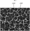
FIG. 2 illustrates an exemplary eutectic cell tissue formed on a surface of an exemplary brake disk according to an exemplary embodiment of the present invention; -
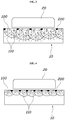
FIGS. 3 and 4 illustrate various amount of generated iron carbide depending on the size of a eutectic cell according to an exemplary embodiment of the present invention; -
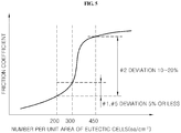
FIG. 5 is a graph depicting a change in a friction coefficient according to the number per unit area of eutectic cells according to an exemplary embodiment of the present invention; -
FIG. 6 illustrates an exemplary friction surface of the brake disk including a plurality of sections according to an exemplary embodiment of the present invention; -
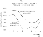
FIG. 7 is a graph depicting various contraction ratios of friction surfaces of exemplary brake disks manufactured according to an exemplary casting method; and -
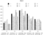
FIG. 8 is a graph depicting numbers of exemplary eutectic cells formed on friction surfaces of exemplary brake disks with different casting methods and different grinding amounts according to an exemplary embodiment of the present invention. - The terminology used herein is merely for mentioning a specific embodiment, and is not intended to limit the present invention. A singular form used herein includes a plural form as long as the word does not indicate obviously the opposite meaning. The term "include" used in the specification specifies specific characteristics, an area, an essence, a step, an operation, an element, and/or a component, and does not exclude existence or addition of other specific characteristics, an area, an essence, a step, an operation, an element, a component and/or a group.
- It is understood that the term "vehicle" or "vehicular" or other similar term as used herein is inclusive of motor vehicles in general such as passenger automobiles including sports utility vehicles (SUV), buses, trucks, various commercial vehicles, watercraft including a variety of boats and ships, aircraft, and the like, and includes hybrid vehicles, electric vehicles, plug-in hybrid electric vehicles, hydrogen-powered vehicles and other alternative fuel vehicles (e.g. fuels derived from resources other than petroleum). As referred to herein, a hybrid vehicle is a vehicle that has two or more sources of power, for example both gasoline-powered and electric-powered vehicles.
- Further, unless specifically stated or obvious from context, as used herein, the term "about" is understood as within a range of normal tolerance in the art, for example within 2 standard deviations of the mean. "About" can be understood as within 10%, 9%, 8%, 7%, 6%, 5%, 4%, 3%, 2%, 1%, 0.5%, 0.1%, 0.05%, or 0.01% of the stated value. Unless otherwise clear from the context, all numerical values provided herein are modified by the term "about."
- Although not differently defined, all terms including the technical term and the scientific term used herein have the same meaning as the meaning that is understood by those skilled in the art to which the present invention pertains. The terms defined in a generally used dictionary are additionally interpreted to have the meaning matched with the related art document and currently disclosed contents, and are not interpreted to have an ideal meaning or a very formal meaning as long as the terms are not defined.
- Hereinafter, a brake disk and a method for manufacturing the same according to an exemplary embodiment of the present invention will be described with reference to the accompanying drawings.
- In one aspect, the brake disk according to the present invention will be described below.
- The brake disk may include a friction surface formed of cast iron. A friction surface of the brake disk my include a plurality of sections in a circumferential direction, and an average of the numbers per unit area of eutectic cells formed on surfaces of the sections may not be greater than about 300 ea/cm2.
- As illustrated in
FIGS. 2 to 4 ,eutectic cells 100 may be formed in abrake disk 10 formed of cast iron. Theeutectic cells 100 may be tissues which are grown to be similar to a spherical shape as a whole. The eutectic cells may be formed by clumping a plurality of plate-shaped graphites 110 and in which ferrite is formed in a space between thegraphites 110, andiron carbides 200 such as Fe3C are formed at boundaries of theeutectic cells 100. - Although the
eutectic cells 100 are tissues that are commonly found in cast iron manufactured through a general casting process, a friction coefficient of theeutectic cells 100 may greatly vary depending on the sizes of theeutectic cells 100, in other words, a difference in the number per unit area of theeutectic cells 100 may be in various ranges. - As illustrated in
FIG. 5 , with an increase in the number per unit area of theeutectic cells 100, the friction coefficient gradually may increase. At this time, the friction coefficient may increase sharply when the number per unit area of theeutectic cells 100 is not less than about 300 ea/cm2. When the number per unit area of theeutectic cells 100 is less than about 300 ea/cm2, the friction coefficient may be reduced and a variation of the friction coefficient may not be increased. However, when the number per unit area of theeutectic cells 100 is greater than about 300 ea/cm2, a deviation of the friction coefficient may increase as the friction coefficient increases sharply. - When the number per unit area of the
eutectic cells 100 is within the predetermined range, for example, about 200-300 ea/cm2, due to the growth of thegraphites 110, lubricating films may be formed increasingly on a friction surface of thebrake disk 10. Further, because abrasive wear is reduced as the number and the total area of theiron carbides 200 formed at the boundaries of theeutectic cells 100 are reduced, the overall friction coefficient may be reduced. - On the other hand, when the number per unit area of the
eutectic cells 100 increases, or alternatively, when the sizes of theeutectic cells 100 decreases, because thegraphites 110 do not increase, lubricating films may not be formed sufficiently on the friction surface of thebrake disk 10. Further, because abrasive wear is caused as the number and the total area of theiron carbides 200 formed at the boundaries of theeutectic cells 100 increase, the overall friction coefficient may increase. - As illustrated in
FIG. 6 , after a circumference of thebrake disc 10 is divided into several sections, when an average of the numbers of eutectic cells, which are measured in the sections, is not greater than about 300 ea/cm2, the friction coefficient may be minimized. - In addition, a deviation of the numbers of the eutectic cells formed in the sections of the
brake disk 10 may suitably not be greater than about 60 ea/cm2. - Even when the average of the numbers of the eutectic cells formed in the
brake disk 10 is not greater than about 300 ea/cm2, when the deviation according to positions is increased, a deviation of the friction coefficient may be increased. Thus, in order to minimize the deviation of the friction coefficient, the deviation of the numbers of the eutectic cells of thebrake disk 10 according to positions may be suitably about 60 ea/cm2 or less. - When the deviation of the friction coefficient of the
brake disk 10 according to positions is reduced, the maximum BTV generated due to the deviation of the friction coefficient may be also reduced. Through this, vibrations generated during braking may be minimized by ultimately reducing a judder phenomenon. - Because any material may be applied to the above-described
brake disk 10 as long as the material is cast iron generally applied to a friction part of a brake disk, the material is not specifically limited. For example, a commercial material such as FC200 may suitably be used as the material. - Further provided is a method for manufacturing a brake disk. The method may include casting a brake disk including the friction surface formed of cast iron, and adjusting the number per unit area of eutectic cells formed on the friction surface of the brake disk to be about 300 ea/cm2 or less by grinding the friction surface of the brake disk in a thickness direction.
- When a cast iron material is casted, an outer portion of the brake disk, which is directly in contact with a mold, may be cooled relatively fast, and a central portion of the brake disk, which is far away from the mold, may be cooled relatively slowly. Because the growth sizes of the graphites are inversely proportional to a cooling rate, the sizes of eutectic cells at the outer portion may decrease, and the sizes of eutectic cells at the central portion may increase.
- Because the sizes of the eutectic cells are inversely proportional to the number per unit area of the eutectic cells, the number per unit area of the eutectic cells may be reduced as the direction on the brake disk from an outer side to the central side of the cast iron material. Thus, when the friction surface of the brake disk formed of cast iron is ground, the number per unit area of the eutectic cells exposed to the friction surface may suitably be gradually reduced.
- Thus, when the friction surface of the brake disk is ground in a thickness direction, as the number per unit area of the eutectic cells is reduced to about 300 ea/cm2 or less, the judder phenomenon may be reduced.
- An amount of grinding of the brake disk in the thickness direction thereof may vary depending on various conditions, and particularly, may be adjusted depending on a contraction ratio in the thickness direction during a casting process.
-
FIG. 7 illustrates contraction ratios of two samples of brake disks having the same shape, which are casted in two kinds of casting methods, in thickness directions thereof. Numerals in a horizontal axis correspond to the divided sections illustrated inFIG. 6 , anarea 1 is a sample manufactured in a first casting method, and anarea 2 means a sample manufactured in a second casting method. In the two casting methods, positions, sizes, shapes, and the like of feeder heads and overflows may be different from each other, but the shapes of resultant castings may be identical to each other. The detailed description thereof will be omitted because it departs from the scope of the present invention. - In both casting methods, molten metals formed of the same material may be inserted, the molten metals may be inoculated twice in a ladle and once in an injection stream, thus three times in total, and a cooling time may be 40 minutes or greater in each mold.
- Although the shapes of final products manufactured by using the two casting methods are identical to each other,
sample 1 had a contraction ratio that was less than about 1%, butsample 2 had a contraction ratio that is greater than about 1.5%. In this way, the contraction ratio of a casting may vary depending on a detailed configuration of a casting method. - Because a casting directly removed from a mold has an uneven surface, additional grinding may be required. In the related art, an amount of grinding has been determined to be inversely proportional to a contraction ratio of a friction surface.
- For instance, an amount of grinding of
sample 1 having a low contraction ratio may be increased, and an amount of grinding of sample #having a high contraction ratio may be decreased. As a result, the shapes of the castings injected from two molds were identical to each other. Accordingly,sample 1 was ground by about 2 to 2.5 mm in a thickness direction thereof, andsample 2 was ground by about 1.5 to 1.9 mm in a thickness direction thereof. - As illustrated in
FIG. 8 , in the case ofsample 1 having a low contraction ratio, the number per unit area of eutectic cells was not greater than about 300 ea/cm2, and a deviation of the eutectic cells was not greater than about 60 ea/cm2. Thus, a friction coefficient was reduced and a deviation of the friction coefficient was reduced, so that the judder phenomenon may be minimized. - However, in the case of
sample 2 having a high contraction ratio, the number per unit area of eutectic cells was greater than 300 ea/cm2, and a deviation of the eutectic cells was greater than 60 ea/cm2. Thus, a friction coefficient was increased and a deviation of the friction coefficient was increased, so that the judder phenomenon may occur more frequently. - Thus, in the present invention, an amount of grinding may be determined to be proportional to a contraction ratio, so that the number per unit area of eutectic cells formed on the friction surface of the brake disk may be adjusted to be about 300 ea/cm2 or less.
- In contrary to the related art, the amount of grinding of
sample 1 may be set to be greater than the amount of grinding ofsample 2, so that a eutectic cell having a larger size, which is located at the center of the casting, may be exposed to the friction surface. -
Samples FIG. 8 were manufactured in the same casting method as that ofsample # 2, and were then ground by different amounts of grinding in a thickness direction of one side of the brake disk. For example,sample 3 was ground by 2 mm,sample 4 was ground by 2.5 mm, andsample 5 was ground by 3 mm. - As a result, because
sample 3 andsample 4 had the numbers of eutectic cells and the deviations, which were not greatly different from those ofsample 2 above, a reduction in the judder phenomenon may not be expected. However,sample 5 has the number of eutectic cells and the deviation, which were greatly reduced, and thus, may be improved to a level that is similar tosample 1. - Accordingly, in order to adjust the number per unit area of eutectic cells to about 300 ea/cm2 and adjust the deviation to about 60 ea/cm2, when the contraction ratio of the brake disk in the thickness direction thereof is less than about 1.5% on average, the amount of grinding in the thickness direction of the one side may be adjusted to be not less than about 2 mm and be less than 3 mm. When the contraction ratio of the brake disk in the thickness direction thereof is not less than about 1.5% on average, the amount of grinding in the thickness direction of the one side may be adjusted to be not less than about 3 mm.
- Even when the contraction ratio of the brake disk in the thickness direction thereof is reduced, a portion of the brake disk, which is directly in contact with the mold, may be grounded in order to arrange the shape of the surface of the casting and remove sections of small eutectic cells formed on the surface of the casting, such that the number per unit area of the eutectic cells may be reduced.
- Thus, regardless of the contraction ratio of the brake disk, the friction surface on the one side of the brake disk may be ground by at least about 2 mm or greater, preferably by about 2.5 mm or greater.
- When the contraction ratio of the brake disk in the thickness direction thereof is less than about 1.5%, an amount of grinding of the friction surface on the one side of the brake disk may be about 3 mm or less, because, even when the friction surface is ground by about 3 mm or greater, the number per unit area of the eutectic cells may not be greatly reduced.
- Meanwhile, when the contraction ratio of the brake disk in the thickness direction thereof is not less than about 1.5%, the friction surface on the one side of the brake disk may be ground by about 3 mm or greater. When the amount of grinding is less than about 3 mm, as in
samples FIG. 8 , the number per unit area of the eutectic cells may increase, and the deviation thereof also may increase. Thus, an objective of the present invention to reduce the judder phenomenon may not be achieved. - Table 1 represents a result obtained by measuring maximum BTVs of samples having different numbers per unit area of eutectic cells under various conditions, for example, when wile an initial speed and a brake torque vary. The unit of the maximum BTV is kgf which is the same as the brake torque.
- As illustrated in
FIG. 8 and represented in Table 1, an average value of the maximum BTVs ofsample 1 andsample 5, in which the number per unit area of the eutectic cells were not greater than about 300 ea/cm2 and the deviation thereof was not greater than about 60 ea/cm2, was less thansample 4. On the other hand, an average value of the maximum BTVs ofsamples - In this way, when the maximum BTV is high, because the judder phenomenon severely may occur during braking, comfort of a passenger may deteriorate sharply.
- Thus, in order to reduce the judder phenomenon during braking, the number per unit area of the eutectic cells and the deviation thereof may be limited as described above.
Table 1 Initial speed Brake torque max BTV (km/h) (kgf) #1 #2 #3 #4 #5 17.8 3.607 5.963 5.938 5.337 2.155 35.5 4.355 8.7 7.674 7.39 3.324 50 53.3 2.639 9.971 10.332 8.143 3.695 71 2.268 9.541 11.496 9.541 4.614 88.8 2.933 5.474 9.971 8.407 4.497 Average 3.16 7.93 9.082 7.764 3.657 17.8 2.737 5.122 5.367 3.861 1.32 35.5 2.463 7.429 6.774 6.51 2.395 100 53.3 2.17 9.501 9.736 8.152 2.991 71 2.19 8.759 10.557 8.211 4.379 88.8 2.542 8.211 10.264 6.843 5.474 Average 2.42 7.804 8.54 6.715 3.312 17.8 2.796 7.634 6.774 3.333 2.151 35.5 2.796 7.849 7.957 9.14 3.011 130 53.3 3.011 9.462 9.892 7.419 3.011 71 3.226 8.71 10.538 7.312 4.086 88.8 2.903 6.559 8.925 5.591 5.161 Average 2.946 8.043 8.817 6.559 3.484 - Although the embodiments of the present invention have been described with reference to the accompanying drawings, it can be understood by those skilled in the art to which the present invention pertains that the present invention may be implemented in other specific forms without changing the technical spirit or the essential feature of the present invention.
- Therefore, it should be understood that the above-described embodiments are not restrictive but illustrative in all aspects. The scope of the present invention is defined not by the detailed description but by the appended claims, and it should be interpreted that the meaning and the range of the appended claims, and all changes or changed forms derived from an equivalent thereof are included in the scope of the present invention.
Claims (6)
- A brake disk having a friction surface formed of cast iron, wherein the friction surface of the brake disk comprises a plurality of sections in a circumferential direction, and an average of numbers per unit area of eutectic cells formed on surfaces of the sections is not greater than about 300 ea/cm2.
- The brake disk of claim 1, wherein a deviation of the numbers per unit area of the eutectic cells formed in the plurality of sections is not greater than about 60 ea/cm2.
- A method of manufacturing a brake disk, comprising:casting a brake disk comprising a friction surface ; andgrinding the friction surface of the brake disk in a thickness direction such that a number per unit area of eutectic cells formed on the friction surface of the brake disk is not greater than about 300 ea/cm2.
- The method of claim 3, wherein in the grinding of the friction surface of the brake disk in the thickness direction, when an average contraction ratio at which the brake disk is contracted in the thickness direction while the brake disk is casted is less than about 1.5%, one side of the friction surface is ground by a degree that is not less than about 2 mm and is less than 3 mm.
- The method of claim 3, wherein in the grinding of the friction surface of the brake disk in the thickness direction, when an average contraction ratio at which the brake disk is contracted in the thickness direction while the brake disk is casted is not less than about 1.5%, one side of the friction surface is ground by about 3 mm or greater.
- A vehicle comprising a brake disk of claim 1.
Applications Claiming Priority (1)
| Application Number | Priority Date | Filing Date | Title |
|---|---|---|---|
| KR1020170113501A KR102507224B1 (en) | 2017-09-05 | 2017-09-05 | Brake disk and manufacturing method for thereof |
Publications (2)
| Publication Number | Publication Date |
|---|---|
| EP3450793A1 true EP3450793A1 (en) | 2019-03-06 |
| EP3450793B1 EP3450793B1 (en) | 2022-06-01 |
Family
ID=60661818
Family Applications (1)
| Application Number | Title | Priority Date | Filing Date |
|---|---|---|---|
| EP17206413.1A Not-in-force EP3450793B1 (en) | 2017-09-05 | 2017-12-11 | Brake disk and method for manufacturing the same |
Country Status (4)
| Country | Link |
|---|---|
| US (2) | US20190072145A1 (en) |
| EP (1) | EP3450793B1 (en) |
| KR (1) | KR102507224B1 (en) |
| CN (1) | CN109420748B (en) |
Families Citing this family (3)
| Publication number | Priority date | Publication date | Assignee | Title |
|---|---|---|---|---|
| KR102507224B1 (en) | 2017-09-05 | 2023-03-08 | 현대자동차주식회사 | Brake disk and manufacturing method for thereof |
| CN112304639B (en) * | 2020-10-30 | 2022-07-08 | 重庆长安汽车股份有限公司 | Vehicle BTV (vehicle to vehicle) complete vehicle testing method |
| DE102023118244A1 (en) * | 2023-07-11 | 2025-01-16 | Audi Aktiengesellschaft | Method for operating a braking system for a motor vehicle, corresponding braking system for a motor vehicle and computer program product |
Citations (1)
| Publication number | Priority date | Publication date | Assignee | Title |
|---|---|---|---|---|
| CN101418413A (en) * | 2008-09-24 | 2009-04-29 | 上海大学 | Niobium alloy cast iron brake disk material and technique for producing the same |
Family Cites Families (12)
| Publication number | Priority date | Publication date | Assignee | Title |
|---|---|---|---|---|
| JP2003053516A (en) * | 2001-08-08 | 2003-02-26 | Suzuki Motor Corp | Control method of spheroidal graphite cast iron structure and mold used for this control method |
| JP2003121395A (en) * | 2001-10-09 | 2003-04-23 | Metal Science Kk | Method for determining spheroidal graphite shape and flake graphite shape in molten metal of cast iron and measuring ratio of graphite spheroidization and number of eutectic cell |
| KR20060040391A (en) | 2004-11-05 | 2006-05-10 | 현대자동차주식회사 | Manufacturing method of brake disc for automobile |
| CN101063471A (en) * | 2006-04-25 | 2007-10-31 | 湘潭高耐合金制造有限公司 | A method of manufacturing a shaft-mounted brake disc |
| KR20090024859A (en) * | 2007-09-05 | 2009-03-10 | 성우오토모티브 주식회사 | Manufacturing method of vehicle brake disc |
| US7922839B2 (en) * | 2007-10-04 | 2011-04-12 | Miks Engineering | Method for brake rotor assembly and manufacture |
| CN101381837A (en) * | 2008-09-27 | 2009-03-11 | 莱州新忠耀机械有限公司 | Traction motor casing new material for high speed motor train set and fabrication technique thereof |
| DE102011010912A1 (en) * | 2011-02-10 | 2012-08-16 | Lucas Automotive Gmbh | Brake pad assembly for a disc brake and method of making a brake pad assembly |
| CN103290301A (en) * | 2013-05-14 | 2013-09-11 | 陕西同心连铸管业科技有限公司 | Austenitic cast iron wear-resistant insert ring inserted in aluminum piston, and preparation method thereof |
| KR101499125B1 (en) * | 2014-07-16 | 2015-03-06 | 주식회사 동성정기 | Brake disc using different metals and manufacturing methods the same |
| KR101610131B1 (en) | 2015-02-10 | 2016-04-11 | (주) 데크카본 | Method for manufacturing motor vehicle brake disc |
| KR102507224B1 (en) | 2017-09-05 | 2023-03-08 | 현대자동차주식회사 | Brake disk and manufacturing method for thereof |
-
2017
- 2017-09-05 KR KR1020170113501A patent/KR102507224B1/en active Active
- 2017-12-11 US US15/837,301 patent/US20190072145A1/en not_active Abandoned
- 2017-12-11 EP EP17206413.1A patent/EP3450793B1/en not_active Not-in-force
- 2017-12-28 CN CN201711471517.9A patent/CN109420748B/en not_active Expired - Fee Related
-
2021
- 2021-02-24 US US17/184,090 patent/US12123469B2/en active Active
Patent Citations (1)
| Publication number | Priority date | Publication date | Assignee | Title |
|---|---|---|---|---|
| CN101418413A (en) * | 2008-09-24 | 2009-04-29 | 上海大学 | Niobium alloy cast iron brake disk material and technique for producing the same |
Also Published As
| Publication number | Publication date |
|---|---|
| US12123469B2 (en) | 2024-10-22 |
| KR20190027055A (en) | 2019-03-14 |
| US20190072145A1 (en) | 2019-03-07 |
| EP3450793B1 (en) | 2022-06-01 |
| KR102507224B1 (en) | 2023-03-08 |
| US20210190158A1 (en) | 2021-06-24 |
| CN109420748B (en) | 2022-02-11 |
| CN109420748A (en) | 2019-03-05 |
Similar Documents
| Publication | Publication Date | Title |
|---|---|---|
| US12123469B2 (en) | Brake disk and method for manufacturing the same | |
| US20130037359A1 (en) | Brake disc using two different materials and method of producing the same | |
| EP3608043A1 (en) | Sintered friction material | |
| US20150136546A1 (en) | Brake disc comprising heterogeneous materials and method for manufacturing the same | |
| KR102417740B1 (en) | Aluminum alloys and manufacturing methods for applications such as wheels | |
| EP3779162B1 (en) | Cylinder liner for cast-covering, and method for manufacturing cylinder block | |
| CN106735225B (en) | A method of being injected into shape forging aluminium alloy brake disc brake drum | |
| WO2014065188A1 (en) | Rare-earth-magnet production method | |
| US9562578B2 (en) | Brake disc manufactured from heterogeneous materials and method of manufacturing the same | |
| US20160108503A1 (en) | Gray cast iron for cylinder liner and method for manufacturing cylinder liner using the same | |
| US20100321139A1 (en) | Permanent magnet and method of producing permanent magnet | |
| US11578775B2 (en) | Brake lining for railway vehicle, disc brake system for railway vehicle including same, and sintered friction material to be used for brake lining for railway vehicle | |
| KR20200110707A (en) | Steering support yoke | |
| JP2005330560A (en) | Aluminum alloy, bar-shaped material, forging-formed part, machining-formed part, wear resistant aluminum alloy having excellent anodized coating hardness using the same, sliding component and their production method | |
| CN112780708B (en) | Aluminum-based composite material solid brake disc for automobile and preparation method thereof | |
| US10438742B2 (en) | Manufacturing method of rare-earth magnet | |
| KR100802750B1 (en) | Processing method of automobile brake disc | |
| Tsujikawa et al. | Influence of graphite morphology on dry sliding wear of flake graphite cast irons | |
| Malgave et al. | Evaluation of Binder Jet 3D Printed (BJT) M2 Tool Steel against the Wrought M2, Powder Metallurgy (PM) M2 and Laser Powder Bed Fusion (LPBF) Maraging Steel for Mould Application | |
| JP2832091B2 (en) | Method of forming conductive elastic body | |
| KR20190078258A (en) | Magnesium alloy sheet and method for manufacturing the same | |
| JP2799449B2 (en) | Mold structure of vehicle wheel | |
| US20210172034A1 (en) | Preparing method of engine valve | |
| US20190344340A1 (en) | Powder metallurgy method | |
| KR100727134B1 (en) | Brake Disc Manufacturing Method Using Mold for Brake Disc Manufacturing to Reduce Judder |
Legal Events
| Date | Code | Title | Description |
|---|---|---|---|
| PUAI | Public reference made under article 153(3) epc to a published international application that has entered the european phase |
Free format text: ORIGINAL CODE: 0009012 |
|
| STAA | Information on the status of an ep patent application or granted ep patent |
Free format text: STATUS: THE APPLICATION HAS BEEN PUBLISHED |
|
| AK | Designated contracting states |
Kind code of ref document: A1 Designated state(s): AL AT BE BG CH CY CZ DE DK EE ES FI FR GB GR HR HU IE IS IT LI LT LU LV MC MK MT NL NO PL PT RO RS SE SI SK SM TR |
|
| AX | Request for extension of the european patent |
Extension state: BA ME |
|
| STAA | Information on the status of an ep patent application or granted ep patent |
Free format text: STATUS: REQUEST FOR EXAMINATION WAS MADE |
|
| 17P | Request for examination filed |
Effective date: 20190906 |
|
| RBV | Designated contracting states (corrected) |
Designated state(s): AL AT BE BG CH CY CZ DE DK EE ES FI FR GB GR HR HU IE IS IT LI LT LU LV MC MK MT NL NO PL PT RO RS SE SI SK SM TR |
|
| STAA | Information on the status of an ep patent application or granted ep patent |
Free format text: STATUS: EXAMINATION IS IN PROGRESS |
|
| 17Q | First examination report despatched |
Effective date: 20210316 |
|
| RAP3 | Party data changed (applicant data changed or rights of an application transferred) |
Owner name: HYUNDAI MOTOR COMPANY Owner name: KIA CORPORATION |
|
| GRAP | Despatch of communication of intention to grant a patent |
Free format text: ORIGINAL CODE: EPIDOSNIGR1 |
|
| STAA | Information on the status of an ep patent application or granted ep patent |
Free format text: STATUS: GRANT OF PATENT IS INTENDED |
|
| INTG | Intention to grant announced |
Effective date: 20220215 |
|
| GRAS | Grant fee paid |
Free format text: ORIGINAL CODE: EPIDOSNIGR3 |
|
| GRAA | (expected) grant |
Free format text: ORIGINAL CODE: 0009210 |
|
| STAA | Information on the status of an ep patent application or granted ep patent |
Free format text: STATUS: THE PATENT HAS BEEN GRANTED |
|
| AK | Designated contracting states |
Kind code of ref document: B1 Designated state(s): AL AT BE BG CH CY CZ DE DK EE ES FI FR GB GR HR HU IE IS IT LI LT LU LV MC MK MT NL NO PL PT RO RS SE SI SK SM TR |
|
| REG | Reference to a national code |
Ref country code: GB Ref legal event code: FG4D |
|
| REG | Reference to a national code |
Ref country code: AT Ref legal event code: REF Ref document number: 1495562 Country of ref document: AT Kind code of ref document: T Effective date: 20220615 Ref country code: CH Ref legal event code: EP |
|
| REG | Reference to a national code |
Ref country code: IE Ref legal event code: FG4D |
|
| REG | Reference to a national code |
Ref country code: DE Ref legal event code: R096 Ref document number: 602017057961 Country of ref document: DE |
|
| REG | Reference to a national code |
Ref country code: LT Ref legal event code: MG9D |
|
| REG | Reference to a national code |
Ref country code: NL Ref legal event code: MP Effective date: 20220601 |
|
| PG25 | Lapsed in a contracting state [announced via postgrant information from national office to epo] |
Ref country code: SE Free format text: LAPSE BECAUSE OF FAILURE TO SUBMIT A TRANSLATION OF THE DESCRIPTION OR TO PAY THE FEE WITHIN THE PRESCRIBED TIME-LIMIT Effective date: 20220601 Ref country code: NO Free format text: LAPSE BECAUSE OF FAILURE TO SUBMIT A TRANSLATION OF THE DESCRIPTION OR TO PAY THE FEE WITHIN THE PRESCRIBED TIME-LIMIT Effective date: 20220901 Ref country code: LT Free format text: LAPSE BECAUSE OF FAILURE TO SUBMIT A TRANSLATION OF THE DESCRIPTION OR TO PAY THE FEE WITHIN THE PRESCRIBED TIME-LIMIT Effective date: 20220601 Ref country code: HR Free format text: LAPSE BECAUSE OF FAILURE TO SUBMIT A TRANSLATION OF THE DESCRIPTION OR TO PAY THE FEE WITHIN THE PRESCRIBED TIME-LIMIT Effective date: 20220601 Ref country code: GR Free format text: LAPSE BECAUSE OF FAILURE TO SUBMIT A TRANSLATION OF THE DESCRIPTION OR TO PAY THE FEE WITHIN THE PRESCRIBED TIME-LIMIT Effective date: 20220902 Ref country code: FI Free format text: LAPSE BECAUSE OF FAILURE TO SUBMIT A TRANSLATION OF THE DESCRIPTION OR TO PAY THE FEE WITHIN THE PRESCRIBED TIME-LIMIT Effective date: 20220601 Ref country code: ES Free format text: LAPSE BECAUSE OF FAILURE TO SUBMIT A TRANSLATION OF THE DESCRIPTION OR TO PAY THE FEE WITHIN THE PRESCRIBED TIME-LIMIT Effective date: 20220601 Ref country code: BG Free format text: LAPSE BECAUSE OF FAILURE TO SUBMIT A TRANSLATION OF THE DESCRIPTION OR TO PAY THE FEE WITHIN THE PRESCRIBED TIME-LIMIT Effective date: 20220901 |
|
| REG | Reference to a national code |
Ref country code: AT Ref legal event code: MK05 Ref document number: 1495562 Country of ref document: AT Kind code of ref document: T Effective date: 20220601 |
|
| PG25 | Lapsed in a contracting state [announced via postgrant information from national office to epo] |
Ref country code: RS Free format text: LAPSE BECAUSE OF FAILURE TO SUBMIT A TRANSLATION OF THE DESCRIPTION OR TO PAY THE FEE WITHIN THE PRESCRIBED TIME-LIMIT Effective date: 20220601 Ref country code: PL Free format text: LAPSE BECAUSE OF FAILURE TO SUBMIT A TRANSLATION OF THE DESCRIPTION OR TO PAY THE FEE WITHIN THE PRESCRIBED TIME-LIMIT Effective date: 20220601 Ref country code: LV Free format text: LAPSE BECAUSE OF FAILURE TO SUBMIT A TRANSLATION OF THE DESCRIPTION OR TO PAY THE FEE WITHIN THE PRESCRIBED TIME-LIMIT Effective date: 20220601 |
|
| PG25 | Lapsed in a contracting state [announced via postgrant information from national office to epo] |
Ref country code: NL Free format text: LAPSE BECAUSE OF FAILURE TO SUBMIT A TRANSLATION OF THE DESCRIPTION OR TO PAY THE FEE WITHIN THE PRESCRIBED TIME-LIMIT Effective date: 20220601 |
|
| PG25 | Lapsed in a contracting state [announced via postgrant information from national office to epo] |
Ref country code: SM Free format text: LAPSE BECAUSE OF FAILURE TO SUBMIT A TRANSLATION OF THE DESCRIPTION OR TO PAY THE FEE WITHIN THE PRESCRIBED TIME-LIMIT Effective date: 20220601 Ref country code: SK Free format text: LAPSE BECAUSE OF FAILURE TO SUBMIT A TRANSLATION OF THE DESCRIPTION OR TO PAY THE FEE WITHIN THE PRESCRIBED TIME-LIMIT Effective date: 20220601 Ref country code: RO Free format text: LAPSE BECAUSE OF FAILURE TO SUBMIT A TRANSLATION OF THE DESCRIPTION OR TO PAY THE FEE WITHIN THE PRESCRIBED TIME-LIMIT Effective date: 20220601 Ref country code: PT Free format text: LAPSE BECAUSE OF FAILURE TO SUBMIT A TRANSLATION OF THE DESCRIPTION OR TO PAY THE FEE WITHIN THE PRESCRIBED TIME-LIMIT Effective date: 20221003 Ref country code: EE Free format text: LAPSE BECAUSE OF FAILURE TO SUBMIT A TRANSLATION OF THE DESCRIPTION OR TO PAY THE FEE WITHIN THE PRESCRIBED TIME-LIMIT Effective date: 20220601 Ref country code: CZ Free format text: LAPSE BECAUSE OF FAILURE TO SUBMIT A TRANSLATION OF THE DESCRIPTION OR TO PAY THE FEE WITHIN THE PRESCRIBED TIME-LIMIT Effective date: 20220601 Ref country code: AT Free format text: LAPSE BECAUSE OF FAILURE TO SUBMIT A TRANSLATION OF THE DESCRIPTION OR TO PAY THE FEE WITHIN THE PRESCRIBED TIME-LIMIT Effective date: 20220601 |
|
| PGFP | Annual fee paid to national office [announced via postgrant information from national office to epo] |
Ref country code: GB Payment date: 20221121 Year of fee payment: 6 Ref country code: FR Payment date: 20221121 Year of fee payment: 6 Ref country code: DE Payment date: 20221121 Year of fee payment: 6 |
|
| PG25 | Lapsed in a contracting state [announced via postgrant information from national office to epo] |
Ref country code: IS Free format text: LAPSE BECAUSE OF FAILURE TO SUBMIT A TRANSLATION OF THE DESCRIPTION OR TO PAY THE FEE WITHIN THE PRESCRIBED TIME-LIMIT Effective date: 20221001 |
|
| REG | Reference to a national code |
Ref country code: DE Ref legal event code: R097 Ref document number: 602017057961 Country of ref document: DE |
|
| PG25 | Lapsed in a contracting state [announced via postgrant information from national office to epo] |
Ref country code: AL Free format text: LAPSE BECAUSE OF FAILURE TO SUBMIT A TRANSLATION OF THE DESCRIPTION OR TO PAY THE FEE WITHIN THE PRESCRIBED TIME-LIMIT Effective date: 20220601 |
|
| PLBE | No opposition filed within time limit |
Free format text: ORIGINAL CODE: 0009261 |
|
| STAA | Information on the status of an ep patent application or granted ep patent |
Free format text: STATUS: NO OPPOSITION FILED WITHIN TIME LIMIT |
|
| PG25 | Lapsed in a contracting state [announced via postgrant information from national office to epo] |
Ref country code: DK Free format text: LAPSE BECAUSE OF FAILURE TO SUBMIT A TRANSLATION OF THE DESCRIPTION OR TO PAY THE FEE WITHIN THE PRESCRIBED TIME-LIMIT Effective date: 20220601 |
|
| 26N | No opposition filed |
Effective date: 20230302 |
|
| PG25 | Lapsed in a contracting state [announced via postgrant information from national office to epo] |
Ref country code: SI Free format text: LAPSE BECAUSE OF FAILURE TO SUBMIT A TRANSLATION OF THE DESCRIPTION OR TO PAY THE FEE WITHIN THE PRESCRIBED TIME-LIMIT Effective date: 20220601 |
|
| REG | Reference to a national code |
Ref country code: CH Ref legal event code: PL |
|
| REG | Reference to a national code |
Ref country code: BE Ref legal event code: MM Effective date: 20221231 |
|
| PG25 | Lapsed in a contracting state [announced via postgrant information from national office to epo] |
Ref country code: LU Free format text: LAPSE BECAUSE OF NON-PAYMENT OF DUE FEES Effective date: 20221211 |
|
| PG25 | Lapsed in a contracting state [announced via postgrant information from national office to epo] |
Ref country code: LI Free format text: LAPSE BECAUSE OF NON-PAYMENT OF DUE FEES Effective date: 20221231 Ref country code: IE Free format text: LAPSE BECAUSE OF NON-PAYMENT OF DUE FEES Effective date: 20221211 Ref country code: CH Free format text: LAPSE BECAUSE OF NON-PAYMENT OF DUE FEES Effective date: 20221231 |
|
| PG25 | Lapsed in a contracting state [announced via postgrant information from national office to epo] |
Ref country code: BE Free format text: LAPSE BECAUSE OF NON-PAYMENT OF DUE FEES Effective date: 20221231 |
|
| PG25 | Lapsed in a contracting state [announced via postgrant information from national office to epo] |
Ref country code: IT Free format text: LAPSE BECAUSE OF FAILURE TO SUBMIT A TRANSLATION OF THE DESCRIPTION OR TO PAY THE FEE WITHIN THE PRESCRIBED TIME-LIMIT Effective date: 20220601 |
|
| PG25 | Lapsed in a contracting state [announced via postgrant information from national office to epo] |
Ref country code: HU Free format text: LAPSE BECAUSE OF FAILURE TO SUBMIT A TRANSLATION OF THE DESCRIPTION OR TO PAY THE FEE WITHIN THE PRESCRIBED TIME-LIMIT; INVALID AB INITIO Effective date: 20171211 |
|
| PG25 | Lapsed in a contracting state [announced via postgrant information from national office to epo] |
Ref country code: CY Free format text: LAPSE BECAUSE OF FAILURE TO SUBMIT A TRANSLATION OF THE DESCRIPTION OR TO PAY THE FEE WITHIN THE PRESCRIBED TIME-LIMIT Effective date: 20220601 |
|
| PG25 | Lapsed in a contracting state [announced via postgrant information from national office to epo] |
Ref country code: MK Free format text: LAPSE BECAUSE OF FAILURE TO SUBMIT A TRANSLATION OF THE DESCRIPTION OR TO PAY THE FEE WITHIN THE PRESCRIBED TIME-LIMIT Effective date: 20220601 |
|
| PG25 | Lapsed in a contracting state [announced via postgrant information from national office to epo] |
Ref country code: MC Free format text: LAPSE BECAUSE OF FAILURE TO SUBMIT A TRANSLATION OF THE DESCRIPTION OR TO PAY THE FEE WITHIN THE PRESCRIBED TIME-LIMIT Effective date: 20220601 |
|
| PG25 | Lapsed in a contracting state [announced via postgrant information from national office to epo] |
Ref country code: MC Free format text: LAPSE BECAUSE OF FAILURE TO SUBMIT A TRANSLATION OF THE DESCRIPTION OR TO PAY THE FEE WITHIN THE PRESCRIBED TIME-LIMIT Effective date: 20220601 |
|
| REG | Reference to a national code |
Ref country code: DE Ref legal event code: R119 Ref document number: 602017057961 Country of ref document: DE |
|
| GBPC | Gb: european patent ceased through non-payment of renewal fee |
Effective date: 20231211 |
|
| PG25 | Lapsed in a contracting state [announced via postgrant information from national office to epo] |
Ref country code: MT Free format text: LAPSE BECAUSE OF FAILURE TO SUBMIT A TRANSLATION OF THE DESCRIPTION OR TO PAY THE FEE WITHIN THE PRESCRIBED TIME-LIMIT Effective date: 20220601 |
|
| PG25 | Lapsed in a contracting state [announced via postgrant information from national office to epo] |
Ref country code: DE Free format text: LAPSE BECAUSE OF NON-PAYMENT OF DUE FEES Effective date: 20240702 |
|
| PG25 | Lapsed in a contracting state [announced via postgrant information from national office to epo] |
Ref country code: GB Free format text: LAPSE BECAUSE OF NON-PAYMENT OF DUE FEES Effective date: 20231211 |
|
| PG25 | Lapsed in a contracting state [announced via postgrant information from national office to epo] |
Ref country code: FR Free format text: LAPSE BECAUSE OF NON-PAYMENT OF DUE FEES Effective date: 20231231 |
|
| PG25 | Lapsed in a contracting state [announced via postgrant information from national office to epo] |
Ref country code: GB Free format text: LAPSE BECAUSE OF NON-PAYMENT OF DUE FEES Effective date: 20231211 Ref country code: FR Free format text: LAPSE BECAUSE OF NON-PAYMENT OF DUE FEES Effective date: 20231231 Ref country code: DE Free format text: LAPSE BECAUSE OF NON-PAYMENT OF DUE FEES Effective date: 20240702 |
|
| PG25 | Lapsed in a contracting state [announced via postgrant information from national office to epo] |
Ref country code: BG Free format text: LAPSE BECAUSE OF FAILURE TO SUBMIT A TRANSLATION OF THE DESCRIPTION OR TO PAY THE FEE WITHIN THE PRESCRIBED TIME-LIMIT Effective date: 20220601 |
|
| PG25 | Lapsed in a contracting state [announced via postgrant information from national office to epo] |
Ref country code: BG Free format text: LAPSE BECAUSE OF FAILURE TO SUBMIT A TRANSLATION OF THE DESCRIPTION OR TO PAY THE FEE WITHIN THE PRESCRIBED TIME-LIMIT Effective date: 20220601 |
|
| PG25 | Lapsed in a contracting state [announced via postgrant information from national office to epo] |
Ref country code: TR Free format text: LAPSE BECAUSE OF FAILURE TO SUBMIT A TRANSLATION OF THE DESCRIPTION OR TO PAY THE FEE WITHIN THE PRESCRIBED TIME-LIMIT Effective date: 20220601 |