EP3450774A1 - Cylinder operation state monitoring device - Google Patents
Cylinder operation state monitoring device Download PDFInfo
- Publication number
- EP3450774A1 EP3450774A1 EP17789222.1A EP17789222A EP3450774A1 EP 3450774 A1 EP3450774 A1 EP 3450774A1 EP 17789222 A EP17789222 A EP 17789222A EP 3450774 A1 EP3450774 A1 EP 3450774A1
- Authority
- EP
- European Patent Office
- Prior art keywords
- pressure
- piston
- flow rate
- differential pressure
- cylinder
- Prior art date
- Legal status (The legal status is an assumption and is not a legal conclusion. Google has not performed a legal analysis and makes no representation as to the accuracy of the status listed.)
- Granted
Links
Images






Classifications
-
- F—MECHANICAL ENGINEERING; LIGHTING; HEATING; WEAPONS; BLASTING
- F15—FLUID-PRESSURE ACTUATORS; HYDRAULICS OR PNEUMATICS IN GENERAL
- F15B—SYSTEMS ACTING BY MEANS OF FLUIDS IN GENERAL; FLUID-PRESSURE ACTUATORS, e.g. SERVOMOTORS; DETAILS OF FLUID-PRESSURE SYSTEMS, NOT OTHERWISE PROVIDED FOR
- F15B15/00—Fluid-actuated devices for displacing a member from one position to another; Gearing associated therewith
- F15B15/20—Other details, e.g. assembly with regulating devices
- F15B15/28—Means for indicating the position, e.g. end of stroke
- F15B15/2815—Position sensing, i.e. means for continuous measurement of position, e.g. LVDT
- F15B15/2838—Position sensing, i.e. means for continuous measurement of position, e.g. LVDT with out using position sensors, e.g. by volume flow measurement or pump speed
-
- F—MECHANICAL ENGINEERING; LIGHTING; HEATING; WEAPONS; BLASTING
- F15—FLUID-PRESSURE ACTUATORS; HYDRAULICS OR PNEUMATICS IN GENERAL
- F15B—SYSTEMS ACTING BY MEANS OF FLUIDS IN GENERAL; FLUID-PRESSURE ACTUATORS, e.g. SERVOMOTORS; DETAILS OF FLUID-PRESSURE SYSTEMS, NOT OTHERWISE PROVIDED FOR
- F15B15/00—Fluid-actuated devices for displacing a member from one position to another; Gearing associated therewith
- F15B15/20—Other details, e.g. assembly with regulating devices
- F15B15/28—Means for indicating the position, e.g. end of stroke
-
- F—MECHANICAL ENGINEERING; LIGHTING; HEATING; WEAPONS; BLASTING
- F15—FLUID-PRESSURE ACTUATORS; HYDRAULICS OR PNEUMATICS IN GENERAL
- F15B—SYSTEMS ACTING BY MEANS OF FLUIDS IN GENERAL; FLUID-PRESSURE ACTUATORS, e.g. SERVOMOTORS; DETAILS OF FLUID-PRESSURE SYSTEMS, NOT OTHERWISE PROVIDED FOR
- F15B11/00—Servomotor systems without provision for follow-up action; Circuits therefor
- F15B11/08—Servomotor systems without provision for follow-up action; Circuits therefor with only one servomotor
- F15B11/10—Servomotor systems without provision for follow-up action; Circuits therefor with only one servomotor in which the servomotor position is a function of the pressure also pressure regulators as operating means for such systems, the device itself may be a position indicating system
-
- F—MECHANICAL ENGINEERING; LIGHTING; HEATING; WEAPONS; BLASTING
- F15—FLUID-PRESSURE ACTUATORS; HYDRAULICS OR PNEUMATICS IN GENERAL
- F15B—SYSTEMS ACTING BY MEANS OF FLUIDS IN GENERAL; FLUID-PRESSURE ACTUATORS, e.g. SERVOMOTORS; DETAILS OF FLUID-PRESSURE SYSTEMS, NOT OTHERWISE PROVIDED FOR
- F15B19/00—Testing; Calibrating; Fault detection or monitoring; Simulation or modelling of fluid-pressure systems or apparatus not otherwise provided for
- F15B19/005—Fault detection or monitoring
-
- F—MECHANICAL ENGINEERING; LIGHTING; HEATING; WEAPONS; BLASTING
- F15—FLUID-PRESSURE ACTUATORS; HYDRAULICS OR PNEUMATICS IN GENERAL
- F15B—SYSTEMS ACTING BY MEANS OF FLUIDS IN GENERAL; FLUID-PRESSURE ACTUATORS, e.g. SERVOMOTORS; DETAILS OF FLUID-PRESSURE SYSTEMS, NOT OTHERWISE PROVIDED FOR
- F15B20/00—Safety arrangements for fluid actuator systems; Applications of safety devices in fluid actuator systems; Emergency measures for fluid actuator systems
-
- F—MECHANICAL ENGINEERING; LIGHTING; HEATING; WEAPONS; BLASTING
- F15—FLUID-PRESSURE ACTUATORS; HYDRAULICS OR PNEUMATICS IN GENERAL
- F15B—SYSTEMS ACTING BY MEANS OF FLUIDS IN GENERAL; FLUID-PRESSURE ACTUATORS, e.g. SERVOMOTORS; DETAILS OF FLUID-PRESSURE SYSTEMS, NOT OTHERWISE PROVIDED FOR
- F15B2211/00—Circuits for servomotor systems
- F15B2211/50—Pressure control
- F15B2211/505—Pressure control characterised by the type of pressure control means
- F15B2211/50554—Pressure control characterised by the type of pressure control means the pressure control means controlling a pressure downstream of the pressure control means, e.g. pressure reducing valve
-
- F—MECHANICAL ENGINEERING; LIGHTING; HEATING; WEAPONS; BLASTING
- F15—FLUID-PRESSURE ACTUATORS; HYDRAULICS OR PNEUMATICS IN GENERAL
- F15B—SYSTEMS ACTING BY MEANS OF FLUIDS IN GENERAL; FLUID-PRESSURE ACTUATORS, e.g. SERVOMOTORS; DETAILS OF FLUID-PRESSURE SYSTEMS, NOT OTHERWISE PROVIDED FOR
- F15B2211/00—Circuits for servomotor systems
- F15B2211/50—Pressure control
- F15B2211/515—Pressure control characterised by the connections of the pressure control means in the circuit
- F15B2211/5151—Pressure control characterised by the connections of the pressure control means in the circuit being connected to a pressure source and a directional control valve
-
- F—MECHANICAL ENGINEERING; LIGHTING; HEATING; WEAPONS; BLASTING
- F15—FLUID-PRESSURE ACTUATORS; HYDRAULICS OR PNEUMATICS IN GENERAL
- F15B—SYSTEMS ACTING BY MEANS OF FLUIDS IN GENERAL; FLUID-PRESSURE ACTUATORS, e.g. SERVOMOTORS; DETAILS OF FLUID-PRESSURE SYSTEMS, NOT OTHERWISE PROVIDED FOR
- F15B2211/00—Circuits for servomotor systems
- F15B2211/60—Circuit components or control therefor
- F15B2211/63—Electronic controllers
- F15B2211/6303—Electronic controllers using input signals
- F15B2211/6306—Electronic controllers using input signals representing a pressure
- F15B2211/6313—Electronic controllers using input signals representing a pressure the pressure being a load pressure
-
- F—MECHANICAL ENGINEERING; LIGHTING; HEATING; WEAPONS; BLASTING
- F15—FLUID-PRESSURE ACTUATORS; HYDRAULICS OR PNEUMATICS IN GENERAL
- F15B—SYSTEMS ACTING BY MEANS OF FLUIDS IN GENERAL; FLUID-PRESSURE ACTUATORS, e.g. SERVOMOTORS; DETAILS OF FLUID-PRESSURE SYSTEMS, NOT OTHERWISE PROVIDED FOR
- F15B2211/00—Circuits for servomotor systems
- F15B2211/60—Circuit components or control therefor
- F15B2211/63—Electronic controllers
- F15B2211/6303—Electronic controllers using input signals
- F15B2211/632—Electronic controllers using input signals representing a flow rate
- F15B2211/6326—Electronic controllers using input signals representing a flow rate the flow rate being an output member flow rate
-
- F—MECHANICAL ENGINEERING; LIGHTING; HEATING; WEAPONS; BLASTING
- F15—FLUID-PRESSURE ACTUATORS; HYDRAULICS OR PNEUMATICS IN GENERAL
- F15B—SYSTEMS ACTING BY MEANS OF FLUIDS IN GENERAL; FLUID-PRESSURE ACTUATORS, e.g. SERVOMOTORS; DETAILS OF FLUID-PRESSURE SYSTEMS, NOT OTHERWISE PROVIDED FOR
- F15B2211/00—Circuits for servomotor systems
- F15B2211/60—Circuit components or control therefor
- F15B2211/63—Electronic controllers
- F15B2211/6303—Electronic controllers using input signals
- F15B2211/6336—Electronic controllers using input signals representing a state of the output member, e.g. position, speed or acceleration
-
- F—MECHANICAL ENGINEERING; LIGHTING; HEATING; WEAPONS; BLASTING
- F15—FLUID-PRESSURE ACTUATORS; HYDRAULICS OR PNEUMATICS IN GENERAL
- F15B—SYSTEMS ACTING BY MEANS OF FLUIDS IN GENERAL; FLUID-PRESSURE ACTUATORS, e.g. SERVOMOTORS; DETAILS OF FLUID-PRESSURE SYSTEMS, NOT OTHERWISE PROVIDED FOR
- F15B2211/00—Circuits for servomotor systems
- F15B2211/70—Output members, e.g. hydraulic motors or cylinders or control therefor
- F15B2211/705—Output members, e.g. hydraulic motors or cylinders or control therefor characterised by the type of output members or actuators
- F15B2211/7051—Linear output members
- F15B2211/7053—Double-acting output members
-
- F—MECHANICAL ENGINEERING; LIGHTING; HEATING; WEAPONS; BLASTING
- F15—FLUID-PRESSURE ACTUATORS; HYDRAULICS OR PNEUMATICS IN GENERAL
- F15B—SYSTEMS ACTING BY MEANS OF FLUIDS IN GENERAL; FLUID-PRESSURE ACTUATORS, e.g. SERVOMOTORS; DETAILS OF FLUID-PRESSURE SYSTEMS, NOT OTHERWISE PROVIDED FOR
- F15B2211/00—Circuits for servomotor systems
- F15B2211/70—Output members, e.g. hydraulic motors or cylinders or control therefor
- F15B2211/705—Output members, e.g. hydraulic motors or cylinders or control therefor characterised by the type of output members or actuators
- F15B2211/7051—Linear output members
- F15B2211/7053—Double-acting output members
- F15B2211/7054—Having equal piston areas
-
- F—MECHANICAL ENGINEERING; LIGHTING; HEATING; WEAPONS; BLASTING
- F15—FLUID-PRESSURE ACTUATORS; HYDRAULICS OR PNEUMATICS IN GENERAL
- F15B—SYSTEMS ACTING BY MEANS OF FLUIDS IN GENERAL; FLUID-PRESSURE ACTUATORS, e.g. SERVOMOTORS; DETAILS OF FLUID-PRESSURE SYSTEMS, NOT OTHERWISE PROVIDED FOR
- F15B2211/00—Circuits for servomotor systems
- F15B2211/80—Other types of control related to particular problems or conditions
- F15B2211/857—Monitoring of fluid pressure systems
-
- F—MECHANICAL ENGINEERING; LIGHTING; HEATING; WEAPONS; BLASTING
- F15—FLUID-PRESSURE ACTUATORS; HYDRAULICS OR PNEUMATICS IN GENERAL
- F15B—SYSTEMS ACTING BY MEANS OF FLUIDS IN GENERAL; FLUID-PRESSURE ACTUATORS, e.g. SERVOMOTORS; DETAILS OF FLUID-PRESSURE SYSTEMS, NOT OTHERWISE PROVIDED FOR
- F15B2211/00—Circuits for servomotor systems
- F15B2211/80—Other types of control related to particular problems or conditions
- F15B2211/86—Control during or prevention of abnormal conditions
- F15B2211/863—Control during or prevention of abnormal conditions the abnormal condition being a hydraulic or pneumatic failure
- F15B2211/864—Failure of an output member, e.g. actuator or motor failure
-
- F—MECHANICAL ENGINEERING; LIGHTING; HEATING; WEAPONS; BLASTING
- F15—FLUID-PRESSURE ACTUATORS; HYDRAULICS OR PNEUMATICS IN GENERAL
- F15B—SYSTEMS ACTING BY MEANS OF FLUIDS IN GENERAL; FLUID-PRESSURE ACTUATORS, e.g. SERVOMOTORS; DETAILS OF FLUID-PRESSURE SYSTEMS, NOT OTHERWISE PROVIDED FOR
- F15B2211/00—Circuits for servomotor systems
- F15B2211/80—Other types of control related to particular problems or conditions
- F15B2211/87—Detection of failures
Definitions
- the present invention relates to a cylinder operation state monitoring device having a cylinder body, a piston capable of moving reciprocally between one end and another end inside the cylinder body, and a piston rod integrally connected to the piston.
- a cylinder includes a cylinder body, a piston that moves reciprocally between one end and another end inside the cylinder body, and a piston rod integrally connected to the piston.
- a first cylinder chamber is formed between the one end and the piston inside the cylinder body, and a second cylinder chamber is formed between the other end and the piston inside the cylinder body.
- proximity sensors by installing proximity sensors in the vicinity of the cylinder, detection of the arrival of the piston at the one end or the other end inside the cylinder body has conventionally been carried out.
- limit sensors are installed as such proximity sensors, at a time that a distal end of the piston rod, which protrudes outside of the cylinder body, and the limit sensors come into mechanical contact, contact points in the interior of the limit sensors are switched, and detection signals indicating arrival of the piston are output from the limit sensors.
- Japanese Patent No. 3857187 it is disclosed to incorporate a magnet in a piston rod, and position detecting sensors which detect magnetism of the magnet are provided at the one end and the other end of the cylinder body.
- the present invention has been devised in order to solve the aforementioned problem, and an object of the present invention is to provide a cylinder operation state monitoring device, which is capable of detecting the arrival of a piston at the one end or the other end inside a cylinder body, without installing sensors in the vicinity of the cylinder.
- the present invention relates to an operation state monitoring device for a cylinder in which a piston connected to a piston rod is reciprocally moved between one end and another end inside a cylinder body, by a first cylinder chamber being formed between the one end and the piston inside the cylinder body, together with a second cylinder chamber being formed between the other end and the piston inside the cylinder body, and by a fluid being supplied from a fluid supply source to the first cylinder chamber via a first tube, or the fluid being supplied from the fluid supply source to the second cylinder chamber via a second tube.
- the operation state monitoring device for the cylinder includes a first pressure detecting unit configured to detect a pressure of the fluid inside the first tube, a second pressure detecting unit configured to detect a pressure of the fluid inside the second tube, and a determination unit configured to determine whether or not the piston has reached the one end or the other end inside the cylinder body, on a basis of the respective pressures detected by the first pressure detecting unit and the second pressure detecting unit.
- the piston and the piston rod are moved reciprocally between the one end and the other end inside the cylinder body. More specifically, the piston and the piston rod undergo reciprocal movement in accordance with a change (increase or decrease) in the pressures of the first cylinder chamber and the second cylinder chamber in accordance with a supplying operation of the fluid.
- the pressure of the fluid inside the first tube corresponding to the pressure of the first cylinder chamber is detected by the first pressure detecting unit, while on the other hand, the pressure of the fluid inside the second tube corresponding to the pressure of the second cylinder chamber is detected by the second pressure detecting unit. Accordingly, the pressure of the fluid inside the first tube and the pressure of the fluid inside the second tube can be easily monitored.
- the present invention on the basis of the pressure of the fluid inside the first tube as detected by the first pressure detecting unit, and the pressure of the fluid inside the second tube as detected by the second pressure detecting unit, it is determined whether or not the piston has reached the one end or the other end inside the cylinder body.
- the cylinder can be suitably used in connection with food related equipment.
- the determination unit may be configured to determine whether or not the piston has reached the one end or the other end inside the cylinder body, on a basis of a differential pressure between a first pressure value which is a pressure value of the fluid inside the first tube detected by the first pressure detecting unit, and a second pressure value which is a pressure value of the fluid inside the second tube detected by the second pressure detecting unit.
- the differential pressure maintains a substantially constant value. Additionally, when the piston reaches the one end or the other end inside the cylinder body, since the pressure in one of the chambers from among the first cylinder chamber and the second cylinder chamber becomes the pressure of the supplied fluid, whereas the pressure in the other chamber drops to substantially zero, the differential pressure increases abruptly. Thus, by grasping such a change in the differential pressure, the determination unit is capable of easily detecting the arrival of the piston at the one end or the other end inside the cylinder body.
- the determination unit may be configured to determine which of the one end and the other end inside the cylinder body that the piston has reached. Consequently, by grasping an abrupt increase in the differential pressure, it is possible to determine whether the piston has reached the one end or the other end inside the cylinder body, and together therewith, by specifying the sign (positive or negative) of the differential pressure at that time, It is possible to recognize which of the one end or the other end inside the cylinder body that the piston has reached.
- the determination unit is configured to determine that the piston has reached the other end inside the cylinder body, when a first differential pressure, which is obtained by subtracting the second pressure value from the first pressure value, exceeds a first reference differential pressure. Further, the determination unit is configured to determine that the piston has reached the one end inside the cylinder body, when a second differential pressure, which is obtained by subtracting the first pressure value from the second pressure value, exceeds a second reference differential pressure. Furthermore, the determination unit is configured to determine that the piston is between the one end and the other end inside the cylinder body, in a case that the first differential pressure is less than or equal to the first reference differential pressure, and the second differential pressure is less than or equal to the second reference differential pressure.
- the arrival of the piston at the one end or the other end inside the cylinder body can be easily determined based only on the first differential pressure and the second differential pressure.
- the first pressure detecting unit may be configured to output to the determination unit a first pressure signal corresponding to the first pressure value
- the second pressure detecting unit may be configured to output to the determination unit a second pressure signal corresponding to the second pressure value.
- the determination unit includes a comparison circuit, is configured to adjust a reference voltage in accordance with the first reference differential pressure or the second reference differential pressure, and determine whether or not the piston has reached the one end or the other end inside the cylinder body by comparing a signal level difference between the input first pressure signal and the input second pressure signal with the reference voltage.
- the determination unit is constituted by an analog circuit, by comparing a signal level difference in accordance with the first differential pressure or the second differential pressure with the reference voltage corresponding to the first reference differential pressure or the second reference differential pressure, it is possible to easily determine whether the piston has reached the one end or the other end inside the cylinder body.
- the operating characteristics of the cylinder differ in accordance with the operating environment of the cylinder and the type of the cylinder.
- the reference voltage adjustable it is possible to detect the arrival of the piston at the one end or the other end inside the cylinder body while setting appropriate specifications in accordance with a user's request.
- the operation state monitoring device further includes a switching valve configured to switch a connection between the fluid supply source and the first tube or the second tube, and a control unit configured to drive the switching valve by supplying a command signal to the switching valve to thereby switch the connection.
- the determination unit in a case that the fluid supply source and the first tube are connected via the switching valve, the determination unit is configured to determine that the piston has reached the other end inside the cylinder body when the first differential pressure, which is obtained by subtracting the second pressure value from the first pressure value, exceeds the first reference differential pressure. On the other hand, if the first differential pressure is less than or equal to the first reference differential pressure, the determination unit is configured to determine that the piston is between the one end and the other end inside the cylinder body.
- the determination unit is configured to determine that the piston has reached the one end inside the cylinder body when the second differential pressure, which is obtained by subtracting the first pressure value from the second pressure value, exceeds the second reference differential pressure. On the other hand, if the second differential pressure is less than or equal to the second reference differential pressure, the determination unit is configured to determine that the piston is between the one end and the other end inside the cylinder body.
- the movement direction of the piston inside the cylinder body is specified on the basis of the connected relationship between the fluid supply source and the first tube or the second tube by the switching valve, and concerning the specified movement direction, it is determined whether or not the piston has reached the one end or the other end inside the cylinder body on the basis of a comparison between the first differential pressure or the second differential pressure and the first reference differential pressure or the second reference differential pressure. Consequently, it is possible to efficiently and reliably detect the arrival of the piston at the one end or the other end inside the cylinder body.
- the operation state monitoring device further includes a time measuring unit configured to measure time from a time at which the control unit begins to supply the command signal to the switching valve.
- the determination unit is configured to, in a case that the first differential pressure exceeds the first reference differential pressure or the second differential pressure exceeds the second reference differential pressure, and if a measured time of the time measuring unit lies within a reference time range, determine that the piston has reached the one end or the other end inside the cylinder body. On the other hand, if the measured time deviates from the reference time range, the determination unit is configured to determine that the reciprocal motion operation of the piston and the piston rod is abnormal.
- the arrival time period of the piston at the one end or the other end inside the cylinder body may be shorter or longer in comparison with the arrival time period thereof in a normal state. Therefore, it is difficult to detect such an abnormal condition merely by comparing the first differential pressure or the second differential pressure with the first reference differential pressure or the second reference differential pressure.
- the third determination method if the time measured by the time measuring unit lies within the reference time range, the cylinder, etc., is in a normal state, and by the piston and the piston rod carrying out reciprocal movement in a normal manner, it is determined that the piston has reached the one end or the other end inside the cylinder body. On the other hand, if the measured time deviates from the reference time range, it is determined that the cylinder, etc., is in an abnormal state, and that the reciprocal motion of the piston and the piston rod is abnormal. Consequently, it is possible to easily detect an abnormality of the cylinder or the like, as well as an abnormality of the reciprocal movement operation of the piston and the piston rod.
- the operation state monitoring device further includes a first flow rate detecting unit configured to detect a flow rate of the fluid inside the first tube as a first flow rate, and a second flow rate detecting unit configured to detect a flow rate of the fluid inside the second tube as a second flow rate.
- the determination unit in a case that the first differential pressure exceeds the first reference differential pressure, and if a first flow rate difference, which is obtained by subtracting the second flow rate from the first flow rate, is less than a first reference flow rate difference, the determination unit is configured to determine that the piston has reached the other end inside the cylinder body. On the other hand, if the first flow rate difference is greater than or equal to the first reference flow rate difference, the determination unit is configured to determine that the piston is between the one end and the other end inside the cylinder body.
- the determination unit is configured to determine that the piston has reached the one end inside the cylinder body.
- the determination unit is configured to determine that the piston is between the one end and the other end inside the cylinder body.
- the determination unit compares the first flow rate difference or the second flow rate difference with the first reference flow rate difference or the second reference flow rate difference. Consequently, the reliability of the determination result in relation to the arrival of the piston at the one end or the other end inside the cylinder body can be improved.
- the operation state monitoring device further includes a first flow rate detecting unit configured to detect a flow rate of the fluid inside the first tube as a first flow rate, a second flow rate detecting unit configured to detect a flow rate of the fluid inside the second tube as a second flow rate, and an integral flow rate calculating unit configured to calculate a first integral flow rate by integrating the first flow rate, or to calculate a second integral flow rate by integrating the second flow rate.
- the determination unit in a case that the first differential pressure exceeds the first reference differential pressure or the second differential pressure exceeds the second reference differential pressure, and if the first integral flow rate or the second integral flow rate lies within a reference flow rate range, the determination unit is configured to determine that the piston has reached the one end or the other end inside the cylinder body. On the other hand, if the first integral flow rate or the second integral flow rate deviates from the reference flow rate range, the determination unit is configured to determine that a reciprocal motion operation of the piston and the piston rod is abnormal.
- the operation state monitoring device may further include a notification unit configured to issue a notification of a determination result to exterior, in a case that the determination unit determines that the reciprocal motion of the piston and the piston rod is abnormal. In accordance with this feature, it is possible to notify the user of the occurrence of an abnormal state.
- the switching valve is a single acting or double acting type of solenoid valve.
- double acting type solenoid valves there are included a solenoid type electromagnetic valve in which solenoids are provided on both sides of the electromagnetic valve, and a solenoid type electromagnetic valve in which a plurality of solenoids are arranged on one side of the electromagnetic valve.
- the determination process in the determination unit may be performed by way of digital signal processing.
- the operation state monitoring device further includes a reference value setting unit configured to set at least the first reference differential pressure and the second reference differential pressure, a display unit configured to display at least the first reference differential pressure and the second reference differential pressure that were set, and a storage unit configured to store at least the first reference differential pressure and the second reference differential pressure that were set.
- the first pressure detecting unit is configured to output a first pressure signal corresponding to the first pressure value to the determination unit
- the second pressure detecting unit is configured to output a second pressure signal corresponding to the second pressure value to the determination unit.
- the determination unit is configured to include a microcomputer, and using the first pressure value and the second pressure value in accordance with the input first pressure signal and the input second pressure signal, and the first reference differential pressure and the second reference differential pressure that were set, the determination unit is configured to determine whether or not the piston has reached the one end or the other end inside the cylinder body.
- the operation state monitoring device may further include an input/output unit configured to input to the determination unit the respective pressures detected by at least the first pressure detecting unit and the second pressure detecting unit, and to output to exterior a determination result of the determination unit.
- the cylinder preferably is a single-shaft type cylinder in which the piston rod is integrally connected to the piston on a side of the first cylinder chamber or on a side of the second cylinder chamber, or alternatively, is a double-shaft type cylinder in which piston rods are integrally connected to the piston respectively on the side of the first cylinder chamber and on the side of the second cylinder chamber.
- FIG. 1 is a block diagram of a cylinder operation state monitoring device 10 according to the present embodiment (hereinafter, also referred to as a monitoring device 10 according to the present embodiment).
- the monitoring device 10 functions as a monitoring device for monitoring an operation state of a cylinder 12.
- the cylinder 12 includes a cylinder body 14, a piston 16 movably disposed in the interior of the cylinder body 14, and a piston rod 18 connected to the piston 16.
- a first cylinder chamber 20 is formed between the piston 16 and one end on the left side of FIG. 1
- a second cylinder chamber 22 is formed between the piston 16 and another end on the right side of FIG. 1 .
- the piston rod 18 is connected to a side surface of the piston 16 facing toward the second cylinder chamber 22, and the distal end of the piston rod 18 extends outwardly from the right end of the cylinder body 14. Accordingly, the cylinder 12 is a single-shaft type cylinder.
- a first port 24 is formed on a side surface of the cylinder body 14 on the side of the first cylinder chamber 20, and one end of a first tube 26 is connected to the first port 24.
- a second port 28 is formed on a side surface of the cylinder body 14 on the side of the second cylinder chamber 22, and one end of a second tube 30 is connected to the second port 28.
- the other end of the first tube 26 is connected to a first connection port 34 of a switching valve 32. Further, the other end of the second tube 30 is connected to a second connection port 36 of the switching valve 32.
- a supply tube 40 is connected to a supply port 38 of the switching valve 32. The supply tube 40 is connected to a fluid supply source 42, and a pressure reducing valve 44 is provided midway in the supply tube 40.
- the switching valve 32 is a single acting type 5-port solenoid valve, which is driven when a command signal (current) is supplied to a solenoid 46 from the exterior.
- the switching valve 32 is not limited to being the solenoid valve shown in FIG. 1 , but may be another type of solenoid valve.
- two single-acting three-port solenoid valves may be prepared, and one of the solenoid valves may be used as a solenoid valve for the first tube 26 (a solenoid valve for controlling the pressure of the first cylinder chamber 20), together with the other solenoid valve being used as a solenoid valve for the second tube 30 (a solenoid valve for controlling the pressure of the second cylinder chamber 22).
- a single acting type solenoid valve a double acting type solenoid valve may be used as the switching valve 32.
- solenoid type electromagnetic valve in which solenoids are provided on both sides of the electromagnetic valve, and a solenoid type electromagnetic valve in which a plurality of solenoids are arranged on one side of the electromagnetic valve.
- the supply port 38 and the second connection port 36 communicate with each other, together with the first connection port 34 being opened to the exterior. Consequently, the fluid supplied from the fluid supply source 42 is converted into a predetermined pressure by the pressure reducing valve 44, and is supplied via the supply tube 40 to the supply port 38 of the switching valve 32.
- the fluid (pressure fluid) after pressure conversion thereof is supplied to the second cylinder chamber 22 via the supply port 38, the second connection port 36, the second tube 30, and the second port 28.
- the piston 16 is pressed by the pressure fluid toward the side of the first cylinder chamber 20, and moves in the direction of the arrow C. Together therewith, the fluid (pressure fluid) inside the first cylinder chamber 20, which is pressed by the piston 16, is discharged to the exterior from the first port 24 via the first tube 26, the first connection port 34, and the switching valve 32.
- the supply port 38 and the first connection port 34 communicate with each other, together with the second connection port 36 being opened to the exterior. Consequently, the pressure fluid, which is supplied from the fluid supply source 42 and converted into a predetermined pressure by the pressure reducing valve 44, is supplied from the supply tube 40 to the first cylinder chamber 20 via the supply port 38, the first connection port 34, the first tube 26, and the first port 24.
- the piston 16 is pressed by the pressure fluid toward the side of the second cylinder chamber 22, and moves in the direction of the arrow D. Together therewith, the pressure fluid inside the second cylinder chamber 22, which is pressed by the piston 16, is discharged to the exterior from the second port 28 via the second tube 30, the second connection port 36, and the switching valve 32.
- the pressure fluid is supplied from the fluid supply source 42 to the first cylinder chamber 20 via the first tube 26, or alternatively, the pressure fluid is supplied to the second cylinder chamber 22 via the second tube 30, whereby the piston 16 and the piston rod 18 can be made to move reciprocally in the direction of the arrow C and the direction of the arrow D.
- the cylinder 12 is a double acting type cylinder.
- a distal end position of the piston rod 18 when the piston 16 is moved to the one end inside the cylinder body 14 along the direction of the arrow C is defined as a position A
- the distal end position of the piston rod 18 when the piston 16 is moved to the other end inside the cylinder body 14 along the direction of the arrow D is defined as a position B.
- the case in which the piston 16 moves from the one end to the other end inside the cylinder body 14 along the direction of the arrow D during energization of the solenoid 46 (when the switching valve 32 is ON) may also be referred to as "advancement".
- the other end which is the end of the stroke, and the position B may be referred to as a "first end".
- the case in which the piston 16 moves from the other end to the one end inside the cylinder body 14 along the direction of the arrow C during non-energization of the solenoid 46 (when the switching valve 32 is OFF) may also be referred to as "retraction”.
- the piston 16 reaches the one end inside the cylinder body 14 and the distal end position of the piston rod 18 reaches the position A the one end, which is the end of the stroke, and the position A may be referred to as a "second end".
- the monitoring device 10 in addition to the fluid supply source 42, the pressure reducing valve 44, and the switching valve 32, etc., the monitoring device 10 according to the present embodiment further includes a first pressure sensor 50 (first pressure detecting unit), a second pressure sensor 52 (second pressure detecting unit), and a detector 54 (determination unit).
- first pressure sensor 50 first pressure detecting unit
- second pressure sensor 52 second pressure detecting unit
- detector 54 determination unit
- the first pressure sensor 50 sequentially detects a pressure value (first pressure value, pressure) P1 of the pressure fluid inside the first tube 26, and outputs a first pressure signal in accordance with the detected first pressure value P1 to the detector 54.
- the second pressure sensor 52 sequentially detects a pressure value (second pressure value, pressure) P2 of the pressure fluid inside the second tube 30, and outputs a second pressure signal in accordance with the detected second pressure value P2 to the detector 54.
- the first pressure sensor 50 and the second pressure sensor 52 can adopt and utilize any of various well-known pressure detecting means. More specifically, there can be adopted as the first pressure sensor 50 and the second pressure sensor 52, (1) a strain gauge type pressure detecting means using a metallic strain gauge, a semiconductor strain gauge, or the like, (2) a capacitance type pressure detecting means using a metallic diaphragm, a silicon diaphragm, or the like, (3) an inductance type pressure detecting means, (4) a force balance type pressure detecting means, or (5) a vibration type pressure detecting means. Descriptions concerning such pressure detecting means are omitted herein.
- the detector 54 determines whether or not the piston 16 has reached the one end (second end) or the other end (first end) of the cylinder body 14. As a result of such a determination process, the detector 54 outputs a signal (first end signal) indicating that the piston 16 has reached the first end, or a signal (second end signal) indicating that the piston 16 has reached the second end.
- first end signal indicating that the piston 16 has reached the first end
- second end signal indicating that the piston 16 has reached the second end.
- the monitoring device 10 may adopt the configuration shown in FIG. 2 instead of the configuration shown in FIG. 1 .
- the monitoring device 10 further includes a first flow rate sensor 56 (first flow rate detecting unit), and a second flow rate sensor 58 (second flow rate detecting unit).
- the first flow rate sensor 56 is disposed midway in the first tube 26, and sequentially detects the flow rate (first flow rate) F1 of the pressure fluid inside the first tube 26, and outputs a first flow rate signal in accordance with the detected first flow rate F1 to the detector 54.
- the second flow rate sensor 58 sequentially detects the flow rate (second flow rate) F2 of the pressure fluid inside the second tube 30, and outputs a second flow rate signal in accordance with the detected second flow rate F2 to the detector 54.
- the detector 54 performs a determination process as to whether or not the piston 16 has reached the first end or the second end. In this case as well, as a result of the determination process, the detector 54 outputs the first end signal or the second end signal.
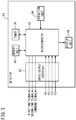
- FIG. 3 is a block diagram showing the internal configuration of the detector 54
- FIG. 4 is a circuit diagram showing another internal configuration of the detector 54. More specifically, the detector 54 of FIG. 3 performs a predetermined digital signal process (determination process) using the first pressure signal and the second pressure signal (as well as the first flow rate signal and the second flow rate signal), thereby generating the first end signal or the second end signal. Further, the detector 54 of FIG. 4 performs a predetermined analog signal process (determination process) using the first pressure signal and the second pressure signal, thereby generating the first end signal or the second end signal.
- a predetermined digital signal process determination process
- the detector 54 of FIG. 4 performs a predetermined analog signal process (determination process) using the first pressure signal and the second pressure signal, thereby generating the first end signal or the second end signal.
- the digital signal processing type detector 54 of FIG. 3 comprises an input/output interface 60 (input/output unit), a microcomputer 62 (control unit, integral flow rate calculating unit), an operation unit 64 (reference value setting unit), a display unit 66 (notification unit), a memory unit 68 (storage unit), and a timer 70 (time measuring unit).
- the monitoring device 10 has a configuration (see FIG. 1 ) in which the first flow rate sensor 56 and the second flow rate sensor 58 are not included, and a configuration (see FIG. 2 ) in which the first flow rate sensor 56 and the second flow rate sensor 58 are included. Therefore, in the description of FIG. 3 , descriptive content related to the first flow rate signal and the second flow rate signal are indicated in parentheses.
- the input/output interface 60 sequentially takes in the first pressure signal and the second pressure signal (as well as the first flow rate signal and the second flow rate signal), and outputs the first pressure value P1 indicated by the first pressure signal and the second pressure value P2 indicated by the second pressure signal (as well as the first flow rate F1 indicated by the first flow rate signal and the second flow rate F2 indicated by the second flow rate signal) to the microcomputer 62. Further, as will be discussed later, in the case that the microcomputer 62 generates the first end signal or the second end signal on the basis of the first pressure value P1 and the second pressure value P2 (as well as the first flow rate F1 and the second flow rate F2), the input/output interface 60 outputs the first end signal or the second end signal to the exterior.
- the operation unit 64 is an operating means such as an operation panel, and an operation button or the like which are operated by the user of the monitoring device 10 and the cylinder 12.
- the operation unit 64 By operating the operation unit 64, the user sets reference values necessary for the digital signal process (determination process) carried out by the microcomputer 62.
- the set reference values are supplied to the microcomputer 62. Accordingly, by operating the operation unit 64, the user can appropriately set the aforementioned reference values in accordance with the operating environment of the cylinder 12, the type of the cylinder 12, and the like. As the reference values, the following items may be cited.
- the setting operation of the above-described respective reference values may be implemented by the user constructing a system including the monitoring device 10 and the cylinder 12, etc., and during a subsequent trial run, by the user operating the operation unit 64 while extracting operating conditions of the cylinder 12.
- the respective reference values may be set or changed via the input/output interface 60 by communication with the exterior or the like.
- the microcomputer 62 calculates the first pressure value P1 and the second pressure value P2 (as well as the first flow rate F1 and the second flow rate F2) that are sequentially input from the input/output interface 60, and calculates the first differential pressure ⁇ P12 and the second differential pressure ⁇ P21 (as well as the first flow rate difference ⁇ F12, the second flow rate difference ⁇ F21, the first integral flow rate Q1, and the second integral flow rate Q2).
- the microcomputer 62 determines whether or not the piston 16 has reached the one end (second end) or the other end (first end) inside the cylinder body 14.
- the microcomputer 62 In the case that the piston 16 has reached the one end inside the cylinder body 14, the microcomputer 62 generates the second end signal indicating that the piston 16 and the piston rod 18 have reached the second end (position A). On the other hand, in the case that the piston 16 has reached the other end inside the cylinder body 14, the microcomputer 62 generates the first end signal indicating that the piston 16 and the piston rod 18 have reached the first end (position B). The generated first end signal or the second end signal is output to the exterior via the input/output interface 60.
- microcomputer 62 is capable of supplying command signals to the solenoid 46 of the switching valve 32 via the input/output interface 60.
- the microcomputer 62 is capable of determining whether or not operation of the piston 16 is abnormal. Further, the microcomputer 62 is also capable of determining whether or not operation of the piston 16 is abnormal on the basis of a comparison between the first integral flow rate Q1 or the second integral flow rate Q2 and the reference flow rate range Qref.
- the microcomputer 62 issues a notification to the user via the display unit 66 of a warning indicating that the operation state of the piston 16 is abnormal, or alternatively, issues a notification to the exterior via the input/output interface 60.
- the display unit 66 displays the reference values set by the user operating the operation unit 64, or displays the results of various types of determination processes executed in the microcomputer 62.
- the memory unit 68 stores the respective reference values set by the operation unit 64.
- the timer 70 measures the stroke time T of the piston 16 inside the cylinder body 14 by initiating measurement of time from the supply start time of the command signal from the microcomputer 62 to the solenoid 46.
- the analog signal processing type detector 54 shown in FIG. 4 includes four operational amplifier circuits 72 to 78.
- the preceding stage operational amplifier circuit 72 is a differential amplifier (comparison circuit), which detects a signal level difference between the first pressure signal (first pressure value P1) and the second pressure signal (second pressure value P2), and outputs a preceding stage output signal indicative of the signal level difference to the subsequent stage operational amplifier circuits 74, 76. Moreover, the preceding stage output signal is an output signal corresponding to the first differential pressure ⁇ P12.
- the operational amplifier circuit 74 is a comparison circuit, which compares the preceding stage output signal with a reference value (reference voltage) V12ref corresponding to the first reference differential pressure ⁇ P12ref, and in the case that the voltage value of the preceding stage output signal exceeds the reference voltage V12ref, inverts the output signal of the operational amplifier circuit 74.
- the output signal the sign of which is inverted, becomes the first end signal.
- the operational amplifier circuit 76 is an inverting amplifier circuit that inverts the preceding stage output signal, and outputs the inverted signal to the operational amplifier circuit 78. Moreover, the output signal (the signal obtained by inverting the preceding stage output signal), which is output from the operational amplifier circuit 76, becomes an output signal in accordance with the second differential pressure ⁇ P21.
- the operational amplifier circuit 78 is a comparison circuit similar to the operational amplifier circuit 74, which compares the output signal from the operational amplifier circuit 76 with a reference value (reference voltage) V21ref corresponding to the second reference differential pressure ⁇ P21ref, and in the case that the voltage value of the output signal exceeds the reference voltage V21ref, inverts the output signal of the operational amplifier circuit 78.
- the output signal the sign of which is inverted, becomes the second end signal.
- the user can appropriately adjust the values of the reference voltages V12ref and V21ref in accordance with the operating environment of the cylinder 12, the type of the cylinder 12, and the like.
- the monitoring device 10 can also be applied to monitoring the operation state of a double-shaft type cylinder 12 in which a piston rod 80 is connected to a side surface of the first cylinder chamber 20 on the piston 16, together with the piston rod 18 being connected to a side surface of the second cylinder chamber 22 on the piston 16.
- a piston rod 80 is connected to a side surface of the first cylinder chamber 20 on the piston 16
- the piston rod 18 being connected to a side surface of the second cylinder chamber 22 on the piston 16.
- the configuration of the monitoring device 10 is the same as in the case of the single-shaft type cylinder 12, detailed description thereof will be omitted.
- the monitoring device 10 is configured in the manner described above. Next, operations of the monitoring device 10 will be described with reference to FIGS. 6 to 18 .
- FIG. 6 is a flowchart showing a determination process executed by the microcomputer 62.
- FIG. 7 is a timing chart showing temporal changes of the first pressure value P1 and the second pressure value P2 when the piston 16 and the piston rod 18 are advanced in the direction of the arrow D in the single-shaft type cylinder 12 (see FIG. 1 ).
- FIG. 8 is a timing chart showing temporal changes of the first pressure value P1 and the second pressure value P2 when the piston 16 and the piston rod 18 are retracted in the direction of the arrow C in the single-shaft type cylinder 12.
- FIG. 9 is a timing chart showing temporal changes of the first pressure value P1 and the second pressure value P2 when the piston 16 and the piston rod 18 are retracted in the direction of the arrow C in the double-shaft type cylinder 12 (see FIG. 5 ).
- the switching valve 32 is driven and is turned ON.
- the connection state of the switching valve 32 is switched, and supply of pressure fluid from the fluid supply source 42 to the first cylinder chamber 20 via the pressure reducing valve 44, the supply port 38, the first connection port 34, and the first tube 26 is initiated.
- the second cylinder chamber 22 communicates with atmosphere via the second tube 30 and the second connection port 36, the pressure fluid of the second cylinder chamber 22 begins to be discharged from the second tube 30 to the exterior via the switching valve 32.
- the first pressure value P1 of the pressure fluid inside the first tube 26 increases abruptly with the passage of time, together with the second pressure value P2 of the pressure fluid inside the second tube 30 decreasing abruptly with the passage of time.
- the first pressure value P1 exceeds the second pressure value P2.
- the first pressure value P1 rises to a predetermined pressure value (for example, the second pressure value P2 (pressure value Pv) before time t1), and the piston 16 starts to be advanced in the direction of the arrow D.
- a predetermined pressure value for example, the second pressure value P2 (pressure value Pv) before time t1
- the piston 16 starts to be advanced in the direction of the arrow D.
- the first pressure value P1 decreases from the pressure value Pv, and together therewith, the second pressure value P2 also decreases.
- the first pressure value P1 and the second pressure value P2 gradually decrease with the passage of time due to changes in the volume of the first cylinder chamber 20 and the second cylinder chamber 22.
- the second pressure value P2 decreases to substantially zero (atmospheric pressure), together with the first pressure value P1 rising toward the pressure value Pv. More specifically, when the piston 16 reaches the other end inside the cylinder body 14, the first differential pressure ⁇ P12 increases abruptly from a constant value.
- the pressure fluid is supplied from the fluid supply source 42 to the first cylinder chamber 20 via the pressure reducing valve 44, the supply port 38, the first connection port 34, and the first tube 26, and the piston 16 is pressed to the other side inside the cylinder body 14.
- the second cylinder chamber 22 communicates with atmosphere via the second tube 30 and the second connection port 36, the fluid inside the second cylinder chamber 22 is discharged from the second tube 30 via the switching valve 32. Accordingly, in the time zone before time t5, the first pressure value P1 is the pressure value Pv, and the second pressure value P2 is substantially zero.
- the switching valve 32 stops being driven and is turned OFF.
- the connection state of the switching valve 32 is switched, and supply of pressure fluid from the fluid supply source 42 to the second cylinder chamber 22 via the pressure reducing valve 44, the supply port 38, the second connection port 36, and the second tube 30 is initiated.
- the pressure fluid of the first cylinder chamber 20 begins to be discharged from the first tube 26 to the exterior via the switching valve 32.
- the second pressure value P2 of the pressure fluid inside the second tube 30 increases abruptly with the passage of time. Thereafter, the first pressure value P1 of the pressure fluid inside the first tube 26 starts to decrease abruptly with the passage of time. As a result, at time t6, the second pressure value P2 exceeds the first pressure value P1.
- the second pressure value P2 rises to a predetermined pressure value (for example, the pressure value Pv), and the piston 16 starts to be retracted in the direction of the arrow C.
- a predetermined pressure value for example, the pressure value Pv
- the second pressure value P2 decreases from the pressure value Pv, and together therewith, the first pressure value P1 also decreases.
- the first pressure value P1 and the second pressure value P2 gradually decrease with the passage of time due to changes in the volume of the first cylinder chamber 20 and the second cylinder chamber 22.
- the absolute value of the first differential pressure ⁇ P12 shown in FIG. 7 , and the absolute value of the second differential pressure ⁇ P21 shown in FIG. 8 differ in size from each other.
- the piston rod 18 is connected to the side surface (right side surface) of the second cylinder chamber 22, whereby the piston areas differ between the right side surface and the side surface (left side surface) of the first cylinder chamber 20 on the piston 16.
- the first pressure value P1 decreases to substantially zero (atmospheric pressure), together with the second pressure value P2 rising toward the pressure value Pv. More specifically, when the piston 16 reaches the one end inside the cylinder body 14, the second differential pressure ⁇ P21 increases abruptly from a constant value.
- the second pressure value P2 of the pressure fluid inside the second tube 30 increases abruptly with the passage of time, together with the first pressure value P1 of the pressure fluid inside the first tube 26 decreasing abruptly with the passage of time.
- the second pressure value P2 exceeds the first pressure value P1.
- the second pressure value P2 rises to a predetermined pressure value (for example, a pressure value in the vicinity of the pressure value Pv), and the piston 16 starts to be retracted in the direction of the arrow C.
- a predetermined pressure value for example, a pressure value in the vicinity of the pressure value Pv
- the piston 16 starts to be retracted in the direction of the arrow C.
- the second pressure value P2 decreases from the pressure value Pv, and together therewith, the first pressure value P1 also decreases.
- piston rods 18, 80 are respectively connected to both side surfaces of the piston 16, and the piston areas on both side surfaces are substantially the same. Therefore, in relation to the time of advancing movement of the piston 16, by replacing a temporal change characteristic of the first pressure value P1 of FIG. 9 with a characteristic of the second pressure value P2, replacing a temporal change characteristic of the second pressure value P2 with the first pressure value P1, and replacing the second differential pressure ⁇ P21 with the first differential pressure ⁇ P12, it is possible to obtain a temporal change characteristic at the time of advancing movement.
- the first determination method by grasping an abrupt change of the first differential pressure ⁇ P12 or the second differential pressure ⁇ P21 at the aforementioned times t4, t8, t12, it is determined whether or not the piston 16 has reached the one end (second end) or the other end (first end) inside the cylinder body 14.
- the first pressure value P1 detected by the first pressure sensor 50, and the second pressure value P2 detected by the second pressure sensor 52 of FIGS. 1 and 5 are sequentially input to the microcomputer 62 via the input/output interface 60 of FIG. 3 .
- the microcomputer 62 executes the determination process in accordance with the first determination method shown in FIG. 6 .
- step S1 of FIG. 6 the microcomputer 62 calculates the first differential pressure ⁇ P12 by subtracting the second pressure value P2 from the first pressure value P1.
- the microcomputer 62 determines whether or not the first differential pressure ⁇ P12 exceeds the first reference differential pressure ⁇ P12ref as a reference value that is stored in advance in the memory unit 68.
- step S2 In the case that ⁇ P12 > ⁇ P12ref (step S1: YES), then in the following step S2, since the signs of ⁇ P12 and ⁇ P12ref are positive, the microcomputer 62 advances the piston 16 from the one end to the other end inside the cylinder body 14, and determines that the piston 16 has reached the other end (the piston rod 18 has reached the position B). In addition, the microcomputer 62 generates the first end signal indicating that the piston 16 has reached the other end, and outputs the first end signal to the exterior via the input/output interface 60. Further, the microcomputer 62 displays the determination result on the display unit 66, and notifies the user of the arrival of the piston 16 at the first end.
- step S3 In the case that ⁇ P21 > ⁇ P21ref (step S3: YES), then in the following step S4, since the signs of ⁇ P21 and ⁇ P21ref are positive, the microcomputer 62 retracts the piston 16 from the other end to the one end inside the cylinder body 14, and determines that the piston 16 has reached the one end (the piston rod 18 has reached the position A). In addition, the microcomputer 62 generates the second end signal indicating that the piston 16 has reached the one end, and outputs the second end signal to the exterior via the input/output interface 60. Further, the microcomputer 62 displays the determination result on the display unit 66, and notifies the user of the arrival of the piston 16 at the second end.
- step S3 NO
- the microcomputer 62 determines that the piston 16 has not reached the one end or the other end inside the cylinder body 14 (the piston 16 is between the one end and the other end) .
- the microcomputer 62 each time the first pressure value P1 and the second pressure value P2 are input, the microcomputer 62 repeatedly executes the determination process of FIG. 6 , and determines whether or not the piston 16 has reached the one end or the other end inside the cylinder body 14.
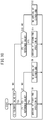
- the second determination method is a process in which, in the first determination method of FIGS. 6 to 9 , the ON or OFF condition of the switching valve 32 (the presence or absence of supply of the command signal from the microcomputer 62 to the solenoid 46) is taken into consideration, to thereby determine whether or not the piston 16 has reached the one end or the other end inside the cylinder body 14. Accordingly, in the description of the second determination method, the same processing as that of the first determination method will be described in a simplified manner, or descriptions thereof will be omitted. This will also be applied to other determination methods described hereinafter.
- the first pressure value P1 and the second pressure value P2 are sequentially input to the microcomputer 62 via the input/output interface 60 of FIG. 3 , and each time the first pressure value P1 and the second pressure value P2 are input, the microcomputer 62 repeatedly executes the determination process in accordance with the second determination method shown in FIG. 10 .
- step S6 of FIG. 10 the microcomputer 62 shown in FIG. 3 determines whether or not the switching valve 32 in the form of a solenoid valve is ON (whether or not a command signal is being supplied to the solenoid 46) .
- step S6 since the supply port 38 and the first connection port 34 are connected and the pressure fluid is supplied to the first cylinder chamber 20 from the fluid supply source 42, the microcomputer 62 determines that the piston 16 is undergoing advancing movement from the one end toward the other end inside the cylinder body 14.
- step S7 the microcomputer 62 calculates the first differential pressure ⁇ P12 in the same manner as in step S1 of FIG. 6 , and determines whether or not the calculated first differential pressure ⁇ P12 exceeds the first reference differential pressure ⁇ P12ref.
- step S8 the microcomputer 62 determines that the piston 16 has reached the other end inside the cylinder body 14 (the piston rod 18 has reached the position B). In this case, the microcomputer 62 outputs the first end signal to the exterior via the input/output interface 60, together with displaying the above-described determination result on the display unit 66, and notifying the user of the arrival of the piston 16 at the first end.
- step S9 the microcomputer 62 determines that the piston 16, although advancing along the direction of the arrow D, has not reached the other end inside the cylinder body 14.
- step S6 in the case that the switching valve 32 is OFF (step S6: NO), since the supply port 38 and the second connection port 36 are connected and the pressure fluid is supplied to the second cylinder chamber 22 from the fluid supply source 42, the microcomputer 62 determines that the piston 16 is undergoing retracting movement from the other end toward the one end inside the cylinder body 14.
- the microcomputer 62 calculates the second differential pressure ⁇ P21 in the same manner as in step S3 of FIG. 6 , and determines whether or not the calculated second differential pressure ⁇ P21 exceeds the second reference differential pressure ⁇ P21ref.
- step S11 the microcomputer 62 determines that the piston 16 has reached the one end inside the cylinder body 14 (the piston rod 18 has reached the position A). In this case, the microcomputer 62 outputs the second end signal to the exterior via the input/output interface 60, together with displaying the above-described determination result on the display unit 66, and notifying the user of the arrival of the piston 16 at the second end.
- step S12 the microcomputer 62 determines that the piston 16, although being retracted along the direction of the arrow C, has not reached the one end inside the cylinder body 14.
- the second determination method in addition to the features of the first determination method, by recognizing the ON or OFF state of the switching valve 32 and specifying the movement direction of the piston 16, it is possible to improve the reliability of the determination process in relation to the arrival of the piston 16 at the one end or the other end inside the cylinder body 14.
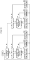
- the third determination method is a process in which, in the second determination method of FIG. 10 , the stroke time of the piston 16 is taken into consideration, to thereby determine whether or not the piston 16 has reached the one end or the other end inside the cylinder body 14.
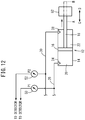
- FIG. 12 is an explanatory view showing a case in which a distal end of the piston rod 18 collides with an obstacle 82, for a case in which the piston 16 and the piston rod 18 are advanced in the direction of the arrow D.
- the first differential pressure ⁇ P12 or the second differential pressure ⁇ P21 may exceed the first reference differential pressure ⁇ P12ref or the second reference differential pressure ⁇ P21ref, and that the arrival of the piston 16 at the one end or the other end may be erroneously detected.
- the setting of the first reference differential pressure ⁇ P12ref or the second reference differential pressure ⁇ P21ref is changed by operation of the operation unit 64 by the user, or in the case that the pressure fluid leaks from the cylinder 12, the first tube 26, the second tube 30, or the like, then even if the piston 16 is located between the one end and the other end inside the cylinder body 14, there is a possibility that the first differential pressure ⁇ P12 or the second differential pressure ⁇ P21 may exceed the first reference differential pressure ⁇ P12ref or the second reference differential pressure ⁇ P21ref, and that the arrival of the piston 16 at the one end or the other end may be erroneously detected.
- the stroke time (arrival time period) T of the piston 16 at the one end or the other end inside the cylinder body 14 may be shorter or longer in comparison with the arrival time period T1 thereof in a normal state.
- the first pressure value P1 and the second pressure value P2 are sequentially input to the microcomputer 62 via the input/output interface 60 of FIG. 3 . Accordingly, each time the first pressure value P1 and the second pressure value P2 are input, the microcomputer 62 repeatedly executes the determination process in accordance with the third determination method shown in FIG. 11 .
- step S13 of FIG. 11 the microcomputer 62 of FIG. 3 determines whether or not the switching valve 32 is ON, in the same manner as in step S6 of FIG. 10 .
- step S13 YES
- the microcomputer 62 determines that the piston 16 is undergoing advancing movement from the one end toward the other end inside the cylinder body 14.
- step S14 the microcomputer 62 calculates the first differential pressure ⁇ P12 in the same manner as in step S1 of FIG. 6 and step S7 of FIG. 10 , and determines whether or not the calculated first differential pressure ⁇ P12 exceeds the first reference differential pressure ⁇ P12ref.
- step S14 determines that there is a possibility that the piston 16 will reach the other end inside the cylinder body 14 (that the piston rod 18 will reach the position B).
- step S15 the microcomputer 62 determines whether or not the stroke time T of the piston 16 from the one end to the other end inside the cylinder body 14 lies within the reference time range Tref that was previously stored in the memory unit 68.
- step S16 the microcomputer 62 determines that the piston 16 has reached the other end inside the cylinder body 14 (the piston rod 18 has reached the position B) due to the normal advancing movement thereof.
- the microcomputer 62 outputs the first end signal to the exterior via the input/output interface 60, together with displaying the above-described determination result on the display unit 66, and notifying the user that the piston 16 has arrived normally at the first end.
- step S17 the microcomputer 62 determines that operation of the piston 16 is abnormal, and warns the user by displaying the determination result on the display unit 66.
- step S18 the microcomputer 62 determines that the piston 16, although advancing along the direction of the arrow D, has not reached the other end inside the cylinder body 14.
- step S13 in the case that the switching valve 32 is OFF (step S13: NO), then by the pressure fluid being supplied to the second cylinder chamber 22 from the fluid supply source 42, the microcomputer 62 determines that the piston 16 is undergoing retracting movement from the other end toward the one end inside the cylinder body 14.
- step S19 the microcomputer 62 calculates the second differential pressure ⁇ P21 in the same manner as in step S3 of FIG. 6 and step S10 of FIG. 10 , and determines whether or not the calculated second differential pressure ⁇ P21 exceeds the second reference differential pressure ⁇ P21ref.
- step S19: YES the microcomputer 62 determines that there is a possibility that the piston 16 will reach the one end inside the cylinder body 14 (that the piston rod 18 will reach the position A). In addition, in the following step S20, the microcomputer 62 determines whether or not the stroke time T of the piston 16 from the other end to the one end inside the cylinder body 14 lies within the reference time range Tref.
- step S21 the microcomputer 62 determines that the piston 16 has reached the one end inside the cylinder body 14 (the piston rod 18 has reached the position A) due to the normal retracting movement thereof.
- the microcomputer 62 outputs the second end signal to the exterior via the input/output interface 60, together with displaying the above-described determination result on the display unit 66, and notifying the user that the piston 16 has arrived normally at the second end.
- step S22 the microcomputer 62 determines that operation of the piston 16 is abnormal, and warns the user by displaying the determination result on the display unit 66.
- step S19 in the case that ⁇ P21 ⁇ ⁇ P21ref (step S19: NO), then in step S23, the microcomputer 62 determines that the piston 16, although being retracted along the direction of the arrow C, has not reached the one end inside the cylinder body 14.
- the stroke time T of the piston 16 is also determined, and therefore, it is possible to detect the presence or absence of an abnormality in the movement operation of the piston 16.
- the fourth determination method is a process in which, in the second determination method of FIG. 10 , the first flow rate F1 and the second flow rate F2 are taken into consideration, to thereby determine whether or not the piston 16 has reached the one end or the other end inside the cylinder body 14.
- FIG. 15 is a timing chart showing temporal changes of the first pressure P1, the second pressure P2, the first flow rate F1, and the second flow rate F2 when the piston 16 and the piston rod 18 are advanced in the direction of the arrow D in the single-shaft type cylinder 12 (see FIG. 2 ). Accordingly, the temporal change characteristics of the first pressure value P1 and the second pressure value P2 shown in FIG. 15 are the same as the temporal change characteristics of the first pressure value P1 and the second pressure value P2 shown in FIG. 7 .
- FIG. 16 is a timing chart showing temporal changes of the first pressure P1, the second pressure P2, the first flow rate F1, and the second flow rate F2 when the piston 16 and the piston rod 18 are retracted in the direction of the arrow C in the single-shaft type cylinder 12. Accordingly, the temporal change characteristics of the first pressure value P1 and the second pressure value P2 shown in FIG. 16 are the same as the temporal change characteristics of the first pressure value P1 and the second pressure value P2 shown in FIG. 8 .
- FIG. 17 is a timing chart showing temporal changes of the first pressure P1, the second pressure P2, the first flow rate F1, and the second flow rate F2 when the piston 16 and the piston rod 18 are retracted in the direction of the arrow C in the double-shaft type cylinder 12 (see FIG. 5 ). Accordingly, the temporal change characteristics of the first pressure value P1 and the second pressure value P2 shown in FIG. 17 are the same as the temporal change characteristics of the first pressure value P1 and the second pressure value P2 shown in FIG. 9 .
- the pressure fluid is supplied to the second cylinder chamber 22 at a time that the switching valve 32 of FIG. 2 is OFF (in the time zone before time t16), and the piston 16 is pressed toward the one end inside the cylinder body 14.
- the fluid of the first cylinder chamber 20 is discharged from the first tube 26 via the switching valve 32.
- the first pressure value P1 is approximately zero
- the second pressure value P2 is the pressure value Pv, together with the first flow rate F1, which is the flow rate of the pressure fluid in the first tube 26, and the second flow rate F2, which is the flow rate of the pressure fluid in the second tube 30, being substantially zero.
- the first pressure value P1 of the pressure fluid inside the first tube 26 increases abruptly with the passage of time, together with the first flow rate F1 (the rate at which the pressure fluid is supplied to the first cylinder chamber 20) increasing abruptly with the passage of time.
- the second pressure value P2 of the pressure fluid inside the second tube 30 decreases abruptly with the passage of time, together with the second flow rate F2 (the rate at which the pressure fluid is discharged from the second cylinder chamber 22) increasing abruptly with the passage of time.
- the first pressure value P1 exceeds the second pressure value P2 at time t17, and at time t18, the first pressure value P1 rises to a predetermined pressure value (for example, the pressure value Pv) and the piston 16 starts to be advanced in the direction of the arrow D, the first flow rate F1 increases in the positive direction (the direction in which the pressure fluid is supplied to the first cylinder chamber 20) with the passage of time, whereas the second flow rate F2 increases in the negative direction (the direction in which the pressure fluid is discharged from the second cylinder chamber 22) with the passage of time.
- a predetermined pressure value for example, the pressure value Pv
- the first pressure value P1 drops from the pressure value Pv due to the change in volume of the first cylinder chamber 20, together with the second pressure value P2 also decreasing, whereby, in the case that the first pressure value P1 and the second pressure value P2 decrease while maintaining a substantially constant first differential pressure ⁇ P12, then after time t19, the first flow rate F1 and the second flow rate F2 become saturated and are maintained at a constant flow rate.
- the switching valve 32 of FIG. 2 when the switching valve 32 of FIG. 2 is ON (in the time zone before time t21), the pressure fluid is supplied to the first cylinder chamber 20, and the piston 16 is pressed toward the other end inside the cylinder body 14.
- the fluid of the second cylinder chamber 22 is discharged from the second tube 30 via the switching valve 32. Accordingly, in the time zone before time t21, the first pressure value P1 is the pressure value Pv, and the second pressure value P2 is substantially zero, together with the first flow rate F1 and the second flow rate F2 being substantially zero.
- the second pressure value P2 of the pressure fluid inside the second tube 30 increases abruptly with the passage of time, together with the second flow rate F2 (the rate at which the pressure fluid is supplied to the second cylinder chamber 22) increasing abruptly in the positive direction with the passage of time.
- the first pressure value P1 of the pressure fluid inside the first tube 26 decreases abruptly with the passage of time, together with the first flow rate F1 (the rate at which the pressure fluid is discharged from the first cylinder chamber 20) increasing abruptly in the negative direction with the passage of time.
- the second pressure value P2 exceeds the first pressure value P1
- the second pressure value P2 rises to a predetermined pressure value (for example, the pressure value Pv)
- the piston 16 starts to be retracted in the direction of the arrow C.
- the second pressure value P2 drops from the pressure value Pv due to the change in volume of the second cylinder chamber 22, together with the first pressure value P1 also decreasing, whereby, in the case that the first pressure value P1 and the second pressure value P2 decrease while maintaining a substantially constant second differential pressure ⁇ P21, then after time t24, the first flow rate F1 and the second flow rate F2 become saturated and are maintained at a constant flow rate.
- the pressure fluid is supplied to the first cylinder chamber 20, and the piston 16 is pressed toward the other end inside the cylinder body 14.
- the fluid of the second cylinder chamber 22 is discharged from the second tube 30 via the switching valve 32. Accordingly, in the time zone before time t26, the first pressure value P1 is the pressure value Pv, and the second pressure value P2 is substantially zero, together with the first flow rate F1 and the second flow rate F2 being substantially zero.
- the second pressure value P2 of the pressure fluid inside the second tube 30 increases abruptly with the passage of time, together with the second flow rate F2 increasing abruptly in the positive direction with the passage of time.
- the first pressure value P1 of the pressure fluid inside the first tube 26 decreases abruptly with the passage of time, together with the first flow rate F1 increasing abruptly in the negative direction with the passage of time.
- the second pressure value P2 exceeds the first pressure value P1
- the second pressure value P2 rises to a predetermined pressure value (for example, a pressure value in the vicinity of the pressure value Pv), and the piston 16 starts to be retracted in the direction of the arrow C.
- the second pressure value P2 drops from the pressure value Pv due to the change in volume of the second cylinder chamber 22, together with the first pressure value P1 also decreasing, whereby, in the case that the first pressure value P1 and the second pressure value P2 decrease while maintaining a substantially constant second differential pressure ⁇ P21, then after time t29, the first flow rate F1 and the second flow rate F2 become saturated and are maintained at a constant flow rate.
- the volume of the first cylinder chamber 20 becomes substantially zero. Consequently, after time t30, the first pressure value P1 decreases to substantially zero, together with the second pressure value P2 rising toward the pressure value Pv. In this case, the first flow rate F1 and the second flow rate F2 decrease to substantially zero from the predetermined flow rate. More specifically, when the piston 16 reaches the one end inside the cylinder body 14, the second differential pressure ⁇ P21 abruptly increases from a constant value, whereas the second flow rate difference ⁇ F21 between the second flow rate F2 and the first flow rate F1 decreases substantially to zero.
- the fourth determination method in addition to the features of the first and second determination methods, by grasping the decrease in the first flow rate difference ⁇ F12 or the second flow rate difference ⁇ F21 after times t20, t25, and t30, the reliability of the determination process as to whether or not the piston 16 has reached the one end or the other end inside the cylinder body 14 is further improved.
- the first pressure value P1 detected by the first pressure sensor 50, the second pressure value P2 detected by the second pressure sensor 52, the first flow rate F1 detected by the first flow rate sensor 56, and the second flow rate F2 detected by the second flow rate sensor 58 of FIG. 2 are sequentially input to the microcomputer 62 via the input/output interface 60 of FIG. 3 .
- the microcomputer 62 executes the determination process in accordance with the fourth determination method shown in FIG. 14 .
- step S24 of FIG. 14 the microcomputer 62 of FIG. 3 determines whether or not the switching valve 32 is ON, in the same manner as in step S6 of FIG. 10 and step S13 of FIG. 11 .
- step S24 YES
- the microcomputer 62 determines that the piston 16 is undergoing advancing movement.
- step S25 the microcomputer 62 calculates the first differential pressure ⁇ P12 in the same manner as in step S1 of FIG. 6 , step S7 of FIG. 10 , and step S14 of FIG. 11 , and determines whether or not the calculated first differential pressure ⁇ P12 exceeds the first reference differential pressure ⁇ P12ref.
- step S25 the microcomputer 62 determines that there is a possibility that the piston 16 will reach the other end inside the cylinder body 14 (that the piston rod 18 will reach the position B).
- step S26 the microcomputer 62 calculates the first flow rate difference ⁇ F12 by subtracting the second flow rate F2 from the first flow rate F1, and it is determined whether or not the calculated first flow rate difference ⁇ F12 is less than the first reference flow rate difference ⁇ F12ref as a reference value that is stored in advance in the memory unit 68.
- step S27 the microcomputer 62 determines that the piston 16 has reached the other end inside the cylinder body 14 (the piston rod 18 has reached the position B) due to the advancing movement thereof.
- the microcomputer 62 outputs the first end signal to the exterior via the input/output interface 60, together with displaying the above-described determination result on the display unit 66, and notifying the user that the piston 16 has arrived at the first end.
- step S28 the microcomputer 62 determines that the piston 16, although advancing along the direction of the arrow D, has not reached the other end inside the cylinder body 14. Further, in step S25, in the case that ⁇ P12 ⁇ ⁇ P12ref (step S25: NO), the microcomputer 62 performs the process of step S28, and determines that the piston 16 has not reached the other end inside the cylinder body 14.
- step S24 in the case that the switching valve 32 is OFF (step S24: NO), then by the pressure fluid being supplied to the second cylinder chamber 22 from the fluid supply source 42, the microcomputer 62 determines that the piston 16 is undergoing retracting movement from the other end toward the one end inside the cylinder body 14.
- step S29 the microcomputer 62 calculates the second differential pressure ⁇ P21 in the same manner as in step S3 of FIG. 6 , step S10 of FIG. 10 , and step S19 of FIG. 11 , and determines whether or not the calculated second differential pressure ⁇ P21 exceeds the second reference differential pressure ⁇ P21ref.
- step S29 the microcomputer 62 determines that there is a possibility that the piston 16 will reach the one end inside the cylinder body 14 (that the piston rod 18 will reach the position A).
- the microcomputer 62 calculates the second flow rate difference ⁇ F21 by subtracting the first flow rate F1 from the second flow rate F2, and it is determined whether or not the calculated second flow rate difference ⁇ F21 is less than the second reference flow rate difference ⁇ F21ref as a reference value that is stored in advance in the memory unit 68.
- step S31 the microcomputer 62 determines that the piston 16 has reached the one end inside the cylinder body 14 (the piston rod 18 has reached the position A) due to the retracting movement thereof.
- the microcomputer 62 outputs the second end signal to the exterior via the input/output interface 60, together with displaying the above-described determination result on the display unit 66, and notifying the user that the piston 16 has arrived at the second end.
- step S32 the microcomputer 62 determines that the piston 16, although being retracted along the direction of the arrow C, has not reached the one end inside the cylinder body 14. Further, in step S29, in the case that ⁇ P21 ⁇ ⁇ P21ref (step S29: NO), the microcomputer 62 performs the process of step S32, and determines that the piston 16 has not reached the one end inside the cylinder body 14.
- the fourth determination method since the determination process using the first flow rate F1 and the second flow rate F2 is also performed in addition to the first and second determination methods, it is possible to reliably determine the arrival of the piston 16 at one end or the other end inside the cylinder body 14.
- an abnormality determination process on the piston 16 is performed which is similar to the third determination method.
- the fifth determination method on the basis of the first integral flow rate Q1, which is an integrated amount of the first flow rate F1 (a total flow rate within a predetermined time period), and the second integral flow rate Q2, which is an integrated amount of the second flow rate F2, the presence or absence of an operation abnormality of the piston 16 is determined.
- step S33 of FIG. 18 the microcomputer 62 of FIG. 3 determines whether or not the switching valve 32 is ON, in the same manner as in step S6 of FIG. 10 , step S13 of FIG. 11 , and step S24 of FIG. 14 .
- step S33 YES
- the microcomputer 62 determines that the piston 16 is undergoing advancing movement.
- step S34 the microcomputer 62 calculates the first differential pressure ⁇ P12 in the same manner as in step S1 of FIG. 6 , step S7 of FIG. 10 , step S14 of FIG. 11 , and step S25 of FIG. 14 , and determines whether or not the calculated first differential pressure ⁇ P12 exceeds the first reference differential pressure ⁇ P12ref.
- step S34 the microcomputer 62 determines that there is a possibility that the piston 16 will reach the other end inside the cylinder body 14 (that the piston rod 18 will reach the position B).
- the microcomputer 62 carries out an integration process of the first flow rate F1 from the point in time of the switching valve 32 being turned ON to the present point in time, and calculates the integrated amount thereof as the first integral flow rate Q1.
- the microcomputer 62 calculates the first integral flow rate Q1 by performing the integration process of the first flow rate F1 from the point in time t16 to the point in time t20 shown in FIG. 15 .
- the microcomputer 62 determines whether or not the first integral flow rate Q1 lies within the reference flow rate range Qref that was previously stored in the memory unit 68.
- step S35 the microcomputer 62 determines that the piston 16 has reached the other end inside the cylinder body 14 (the piston rod 18 has reached the position B) due to the normal advancing movement thereof.
- the microcomputer 62 outputs the first end signal to the exterior via the input/output interface 60, together with displaying the above-described determination result on the display unit 66, and notifying the user that the piston 16 has arrived normally at the first end.
- step S37 the microcomputer 62 determines that operation of the piston 16 is abnormal, and warns the user by displaying the determination result on the display unit 66.
- step S34 in the case that ⁇ P12 ⁇ ⁇ P12ref (step S34: NO), then in step S38, the microcomputer 62 determines that the piston 16, although advancing along the direction of the arrow D, has not reached the other end inside the cylinder body 14.
- step S33 in the case that the switching valve 32 is OFF (step S33: NO), then by the pressure fluid being supplied to the second cylinder chamber 22, the microcomputer 62 determines that the piston 16 is undergoing retracting movement from the other end toward the one end inside the cylinder body 14.
- step S39 the microcomputer 62 calculates the second differential pressure ⁇ P21 in the same manner as in step S3 of FIG. 6 , step S10 of FIG. 10 , step S19 of FIG. 11 , and step S29 of FIG. 14 , and determines whether or not the calculated second differential pressure ⁇ P21 exceeds the second reference differential pressure ⁇ P21ref.
- step S39: YES the microcomputer 62 determines that there is a possibility that the piston 16 will reach the one end inside the cylinder body 14 (that the piston rod 18 will reach the position A).
- the microcomputer 62 carries out an integration process of the second flow rate F2 from the point in time of the switching valve 32 being turned OFF to the present point in time, and calculates the integrated amount thereof as the second integral flow rate Q2.
- the microcomputer 62 calculates the second integral flow rate Q2 by performing the integration process of the second flow rate F2 from the point in time t21 to the point in time t25 shown in FIG. 16 , or from the point in time t26 to the point in time point t30 shown in FIG. 17 .
- the microcomputer 62 determines whether or not the second integral flow rate Q2 lies within the reference flow rate range Qref.
- step S41 the microcomputer 62 determines that the piston 16 has reached the one end inside the cylinder body 14 (the piston rod 18 has reached the position A) due to the normal retracting movement thereof.
- the microcomputer 62 outputs the second end signal to the exterior via the input/output interface 60, together with displaying the above-described determination result on the display unit 66, and notifying the user that the piston 16 has arrived normally at the second end.
- step S42 the microcomputer 62 determines that operation of the piston 16 is abnormal, and warns the user by displaying the determination result on the display unit 66.
- step S43 the microcomputer 62 determines that the piston 16, although being retracted along the direction of the arrow C, has not reached the one end inside the cylinder body 14.
- the piston 16 and the piston rod 18 are capable of moving reciprocally between the one end and the other end inside the cylinder body 14. More specifically, the piston 16 and the piston rod 18 undergo reciprocal movement in accordance with a change (increase or decrease of pressure) in the pressures of the first cylinder chamber 20 and the second cylinder chamber 22 in accordance with a supplying operation of the pressure fluid.
- the pressure fluid in the first cylinder chamber 20 is discharged to the exterior, whereas the pressure in the second cylinder chamber 22 becomes the pressure of the pressure fluid that is supplied via the second tube 30. Further, when the piston 16 has reached the other end inside the cylinder body 14, the pressure in the first cylinder chamber 20 becomes the pressure of the pressure fluid that is supplied via the first tube 26, whereas the pressure fluid in the second cylinder chamber 22 is discharged to the exterior.
- the first pressure value P1 of the pressure fluid inside the first tube 26 corresponding to the pressure of the first cylinder chamber 20 is detected by the first pressure sensor 50
- the second pressure value P2 of the pressure fluid inside the second tube 30 corresponding to the pressure of the second cylinder chamber 22 is detected by the second pressure sensor 52. Accordingly, it is possible to easily monitor the first pressure value P1 and the second pressure value P2.
- the monitoring device 10 on the basis of the first pressure value P1 of the pressure fluid inside the first tube 26 detected by the first pressure sensor 50, and the second pressure value P2 of the pressure fluid inside the second tube 30 detected by the second pressure sensor 52, it is determined whether or not the piston 16 has reached the one end or the other end inside the cylinder body 14.
- the cylinder 12 can be suitably used in connection with food related equipment.
- the first differential pressure ⁇ P12 or the second differential pressure ⁇ P21 is maintained at a substantially constant value.
- the pressure in one of the chambers from among the first cylinder chamber 20 and the second cylinder chamber 22 becomes the pressure (the pressure value Pv) of the supplied pressure fluid, whereas the pressure in the other chamber drops to substantially zero, the first differential pressure ⁇ P12 or the second differential pressure ⁇ P21 increases abruptly.
- the microcomputer 62 of the detector 54 can easily detect the arrival of the piston 16 at the one end or the other end inside the cylinder body 14.
- the microcomputer 62 by grasping an abrupt increase in the first differential pressure ⁇ P12 or the second differential pressure ⁇ P21, it is possible for the microcomputer 62 to determine whether the piston 16 has reached the one end or the other end inside the cylinder body 14, and together therewith, by specifying the sign (positive or negative) of the first differential pressure ⁇ P12 or the second differential pressure ⁇ P21 at that time, to recognize which of the one end or the other end inside the cylinder body 14 that the piston 16 has reached.
- the first determination method at a time that the first differential pressure ⁇ P12 has exceeded the first reference differential pressure ⁇ P12ref, it is determined that the piston 16 has reached the other end inside the cylinder body 14. Further, at a time that the second differential pressure ⁇ P21 has exceeded the second reference differential pressure ⁇ P21ref, it is determined that the piston 16 has reached the one end inside the cylinder body 14. Furthermore, in the case that the first differential pressure ⁇ P12 is less than or equal to the first reference differential pressure ⁇ P12ref, and the second differential pressure ⁇ P21 is less than or equal to the second reference differential pressure ⁇ P21ref, it is determined that the piston 16 is between the one end and the other end inside the cylinder body 14.
- the detector 54 is constituted by the operational amplifier circuits 72 to 78, and is configured to be capable of adjusting the reference voltage V12ref or V21ref in accordance with the first reference differential pressure ⁇ P12ref or the second reference differential pressure ⁇ P21ref.
- the operating characteristics of the cylinder 12 differ in accordance with the operating environment of the cylinder 12 and the type of the cylinder 12.
- the reference voltage V12ref or the reference voltage V21ref adjustable, it is possible to detect the arrival of the piston 16 at the one end or the other end inside the cylinder body 14 while setting appropriate specifications in accordance with the user's request.
- the movement direction of the piston 16 inside the cylinder body 14 can be specified.
- the movement direction of the piston 16 inside the cylinder body 14 is specified on the basis of the connected relationship between the fluid supply source 42 and the first tube 26 or the second tube 30 by the switching valve 32, and concerning the specified movement direction, it is determined whether or not the piston 16 has reached the one end or the other end inside the cylinder body 14 on the basis of a comparison between the first differential pressure P12 or the second differential pressure P21 and the first reference differential pressure ⁇ P12ref or the second reference differential pressure ⁇ P21ref. Consequently, it is possible to efficiently and reliably detect the arrival of the piston 16 at the one end or the other end inside the cylinder body 14.
- the piston areas on both side surfaces of the piston 16 are substantially the same, and the first differential pressure ⁇ P12 and the second differential pressure ⁇ P21 are made small. Accordingly, by specifying the movement direction of the piston 16 in accordance with the second determination method, it is possible to improve the reliability of the above-described determination process.
- the third determination method if the time period (stroke time T) measured by the timer 70 lies within the reference time range Tref, the cylinder 12, etc., is in a normal state, and by the piston 16 and the piston rod 18 carrying out the reciprocal movement operation in a normal manner, it is determined that the piston 16 has reached the one end or the other end inside the cylinder body 14. On the other hand, if the stroke time T deviates from the reference time range Tref, it is determined that the cylinder 12, etc., is in an abnormal state, and the reciprocal movement operation of the piston 16 and the piston rod 18 is abnormal. Consequently, it is possible to easily detect an abnormality of the cylinder 12 or the like, as well as an abnormality in the reciprocal movement operation of the piston 16 and the piston rod 18.
- the microcomputer 62 compares the first flow rate difference ⁇ F12 or the second flow rate difference ⁇ F21 with the first reference flow rate difference ⁇ F12ref or the second reference flow rate difference ⁇ F21ref. Consequently, the reliability of the determination result in relation to the arrival of the piston 16 at the one end or the other end inside the cylinder body 14 can be improved.
- the fifth determination method by calculating the first integral flow rate Q1 or the second integral flow rate Q2, it is possible to estimate the operation stroke until the piston 16 reaches the one end or the other end inside the cylinder body 14. Consequently, the distance that the piston 16 moves can be specified.
- the monitoring device 10 further includes the display unit 66 that displays a notification of the determination result to the exterior. In accordance with this feature, it is possible to notify the user of the occurrence of an abnormal state.
- the reference values such as the first reference differential pressure ⁇ P12ref and the second reference differential pressure ⁇ P21ref, in comparison with a case in which the detector 54 is configured by an analog circuit. Further, by setting the reference values (operating conditions) in advance in accordance with operations of a normal cylinder 12, since teaching is performed with respect to the monitoring device 10, detection of an abnormal state or the like becomes easy to perform.
- the monitoring device 10 as an application of the cylinder 12, it is possible to perform an operation in which the distal ends of the piston rods 18, 80 are pressed against an object, or an object is grasped (clamped) at the distal ends of the piston rods 18, 80.
- a non-illustrated sensor may be provided beforehand in the vicinity of the position (pressing position, gripping position) where the distal ends of the piston rods 18, 80 are stopped by operation of the cylinder 12, whereby it is possible to recognize the completion of work on the object, and proceed to a subsequent process step, on the basis of the detection result of the sensor.
- the stopped position of the distal end parts of the piston rods 18, 80 also differ depending on the size of the object, and therefore, the determination process of completion of operations using the sensor becomes difficult to perform.
- the monitoring device 10 according to the present embodiment by using the aforementioned first, second, fourth, and fifth determination methods (see FIGS. 6 to 10 and FIGS. 14 to 18 ), it is possible to easily determine the completion of operations on the object, and proceed to the next process step.
Landscapes
- Engineering & Computer Science (AREA)
- Physics & Mathematics (AREA)
- Fluid Mechanics (AREA)
- Mechanical Engineering (AREA)
- General Engineering & Computer Science (AREA)
- Chemical & Material Sciences (AREA)
- Analytical Chemistry (AREA)
- Actuator (AREA)
- Fluid-Pressure Circuits (AREA)
Abstract
Description
- The present invention relates to a cylinder operation state monitoring device having a cylinder body, a piston capable of moving reciprocally between one end and another end inside the cylinder body, and a piston rod integrally connected to the piston.
- A cylinder includes a cylinder body, a piston that moves reciprocally between one end and another end inside the cylinder body, and a piston rod integrally connected to the piston. A first cylinder chamber is formed between the one end and the piston inside the cylinder body, and a second cylinder chamber is formed between the other end and the piston inside the cylinder body. In this instance, by supplying fluid from a fluid supply source to the first cylinder chamber via a first tube, or by supplying fluid to the second cylinder chamber via a second tube, the piston and the piston rod are capable of moving reciprocally between the one end and the other end inside the cylinder body.
- Incidentally, by installing proximity sensors in the vicinity of the cylinder, detection of the arrival of the piston at the one end or the other end inside the cylinder body has conventionally been carried out. For example, in the case that limit sensors are installed as such proximity sensors, at a time that a distal end of the piston rod, which protrudes outside of the cylinder body, and the limit sensors come into mechanical contact, contact points in the interior of the limit sensors are switched, and detection signals indicating arrival of the piston are output from the limit sensors. Further, in Japanese Patent No.
3857187 - However, in the conventional technique in which limit sensors are used, since the arrival of the piston is detected by mechanical contact between the piston rod and the limit sensors, there is a problem in that it is necessary to take into consideration the service life, etc., of the contact points.
- On the other hand, in the technique of Japanese Patent No.
3857187 - In this manner, conventionally, in order to detect whether or not a piston has reached the one end or the other end inside the cylinder body, the aforementioned problem occurs because sensors are installed in the vicinity of the cylinder.
- The present invention has been devised in order to solve the aforementioned problem, and an object of the present invention is to provide a cylinder operation state monitoring device, which is capable of detecting the arrival of a piston at the one end or the other end inside a cylinder body, without installing sensors in the vicinity of the cylinder.
- The present invention relates to an operation state monitoring device for a cylinder in which a piston connected to a piston rod is reciprocally moved between one end and another end inside a cylinder body, by a first cylinder chamber being formed between the one end and the piston inside the cylinder body, together with a second cylinder chamber being formed between the other end and the piston inside the cylinder body, and by a fluid being supplied from a fluid supply source to the first cylinder chamber via a first tube, or the fluid being supplied from the fluid supply source to the second cylinder chamber via a second tube.
- In addition, in order to achieve the aforementioned object, the operation state monitoring device for the cylinder according to the present invention includes a first pressure detecting unit configured to detect a pressure of the fluid inside the first tube, a second pressure detecting unit configured to detect a pressure of the fluid inside the second tube, and a determination unit configured to determine whether or not the piston has reached the one end or the other end inside the cylinder body, on a basis of the respective pressures detected by the first pressure detecting unit and the second pressure detecting unit.
- In the cylinder, by supplying fluid from the fluid supply source to the first cylinder chamber or the second cylinder chamber via the first tube or the second tube, the piston and the piston rod are moved reciprocally between the one end and the other end inside the cylinder body. More specifically, the piston and the piston rod undergo reciprocal movement in accordance with a change (increase or decrease) in the pressures of the first cylinder chamber and the second cylinder chamber in accordance with a supplying operation of the fluid.
- In this case, when the piston has reached the one end inside the cylinder body, the fluid in the first cylinder chamber is discharged to the exterior, whereas the pressure in the second cylinder chamber becomes the pressure of the fluid that is supplied via the second tube. Further, when the piston has reached the other end inside the cylinder body, the pressure in the first cylinder chamber becomes the pressure of the fluid that is supplied via the first tube, whereas the fluid in the second cylinder chamber is discharged to the exterior.
- In addition, the pressure of the fluid inside the first tube corresponding to the pressure of the first cylinder chamber is detected by the first pressure detecting unit, while on the other hand, the pressure of the fluid inside the second tube corresponding to the pressure of the second cylinder chamber is detected by the second pressure detecting unit. Accordingly, the pressure of the fluid inside the first tube and the pressure of the fluid inside the second tube can be easily monitored.
- Thus, according to the present invention, on the basis of the pressure of the fluid inside the first tube as detected by the first pressure detecting unit, and the pressure of the fluid inside the second tube as detected by the second pressure detecting unit, it is determined whether or not the piston has reached the one end or the other end inside the cylinder body.
- Consequently, without installing a sensor in the vicinity of the cylinder, it is possible to detect the arrival of the piston at the one end or the other end inside the cylinder body. Further, because there is no need to install a sensor and wiring for the sensor in the vicinity of the cylinder, there is no occurrence of problems such as corrosion of the sensor and wiring therefor in a cleaning process used in connection with food related equipment. As a result, the cylinder can be suitably used in connection with food related equipment.
- In this instance, the determination unit may be configured to determine whether or not the piston has reached the one end or the other end inside the cylinder body, on a basis of a differential pressure between a first pressure value which is a pressure value of the fluid inside the first tube detected by the first pressure detecting unit, and a second pressure value which is a pressure value of the fluid inside the second tube detected by the second pressure detecting unit.
- In the case that the piston moves reciprocally between the one end and the other end inside the cylinder body, the differential pressure maintains a substantially constant value. Additionally, when the piston reaches the one end or the other end inside the cylinder body, since the pressure in one of the chambers from among the first cylinder chamber and the second cylinder chamber becomes the pressure of the supplied fluid, whereas the pressure in the other chamber drops to substantially zero, the differential pressure increases abruptly. Thus, by grasping such a change in the differential pressure, the determination unit is capable of easily detecting the arrival of the piston at the one end or the other end inside the cylinder body.
- In this case, on a basis of the differential pressure between the first pressure value and the second pressure value, and a sign of the differential pressure, the determination unit may be configured to determine which of the one end and the other end inside the cylinder body that the piston has reached. Consequently, by grasping an abrupt increase in the differential pressure, it is possible to determine whether the piston has reached the one end or the other end inside the cylinder body, and together therewith, by specifying the sign (positive or negative) of the differential pressure at that time, It is possible to recognize which of the one end or the other end inside the cylinder body that the piston has reached.
- Specific determination methods (first to fifth determination methods) carried out in the determination unit will be described below.
- As a first determination method, the determination unit is configured to determine that the piston has reached the other end inside the cylinder body, when a first differential pressure, which is obtained by subtracting the second pressure value from the first pressure value, exceeds a first reference differential pressure. Further, the determination unit is configured to determine that the piston has reached the one end inside the cylinder body, when a second differential pressure, which is obtained by subtracting the first pressure value from the second pressure value, exceeds a second reference differential pressure. Furthermore, the determination unit is configured to determine that the piston is between the one end and the other end inside the cylinder body, in a case that the first differential pressure is less than or equal to the first reference differential pressure, and the second differential pressure is less than or equal to the second reference differential pressure.
- In accordance with this feature, the arrival of the piston at the one end or the other end inside the cylinder body can be easily determined based only on the first differential pressure and the second differential pressure.
- Further, in the first determination method, the first pressure detecting unit may be configured to output to the determination unit a first pressure signal corresponding to the first pressure value, and the second pressure detecting unit may be configured to output to the determination unit a second pressure signal corresponding to the second pressure value. In this case, the determination unit includes a comparison circuit, is configured to adjust a reference voltage in accordance with the first reference differential pressure or the second reference differential pressure, and determine whether or not the piston has reached the one end or the other end inside the cylinder body by comparing a signal level difference between the input first pressure signal and the input second pressure signal with the reference voltage.
- In this manner, in the case that the determination unit is constituted by an analog circuit, by comparing a signal level difference in accordance with the first differential pressure or the second differential pressure with the reference voltage corresponding to the first reference differential pressure or the second reference differential pressure, it is possible to easily determine whether the piston has reached the one end or the other end inside the cylinder body.
- Further, the operating characteristics of the cylinder (temporal change characteristics of the first pressure value and the second pressure value) differ in accordance with the operating environment of the cylinder and the type of the cylinder. Thus, by making the reference voltage adjustable, it is possible to detect the arrival of the piston at the one end or the other end inside the cylinder body while setting appropriate specifications in accordance with a user's request.
- As a second determination method, the operation state monitoring device further includes a switching valve configured to switch a connection between the fluid supply source and the first tube or the second tube, and a control unit configured to drive the switching valve by supplying a command signal to the switching valve to thereby switch the connection.
- In the second determination method, in a case that the fluid supply source and the first tube are connected via the switching valve, the determination unit is configured to determine that the piston has reached the other end inside the cylinder body when the first differential pressure, which is obtained by subtracting the second pressure value from the first pressure value, exceeds the first reference differential pressure. On the other hand, if the first differential pressure is less than or equal to the first reference differential pressure, the determination unit is configured to determine that the piston is between the one end and the other end inside the cylinder body.
- Further, in a case that the fluid supply source and the second tube are connected via the switching valve, the determination unit is configured to determine that the piston has reached the one end inside the cylinder body when the second differential pressure, which is obtained by subtracting the first pressure value from the second pressure value, exceeds the second reference differential pressure. On the other hand, if the second differential pressure is less than or equal to the second reference differential pressure, the determination unit is configured to determine that the piston is between the one end and the other end inside the cylinder body.
- By grasping to which of the first tube and the second tube the fluid supply source is connected by the switching valve, it is possible to specify the direction of movement of the piston inside the cylinder body. Thus, according to the second determination method, the movement direction of the piston inside the cylinder body is specified on the basis of the connected relationship between the fluid supply source and the first tube or the second tube by the switching valve, and concerning the specified movement direction, it is determined whether or not the piston has reached the one end or the other end inside the cylinder body on the basis of a comparison between the first differential pressure or the second differential pressure and the first reference differential pressure or the second reference differential pressure. Consequently, it is possible to efficiently and reliably detect the arrival of the piston at the one end or the other end inside the cylinder body.
- As a third determination method, the operation state monitoring device further includes a time measuring unit configured to measure time from a time at which the control unit begins to supply the command signal to the switching valve.
- In the third determination method, the determination unit is configured to, in a case that the first differential pressure exceeds the first reference differential pressure or the second differential pressure exceeds the second reference differential pressure, and if a measured time of the time measuring unit lies within a reference time range, determine that the piston has reached the one end or the other end inside the cylinder body. On the other hand, if the measured time deviates from the reference time range, the determination unit is configured to determine that the reciprocal motion operation of the piston and the piston rod is abnormal.
- For example, in the event of an abnormal condition, such as a case in which a distal end of the piston rod collides with an obstacle, a case in which the first reference differential pressure or the second reference differential pressure undergoes a change in setting, or alternatively, a case in which fluid is leaking from the cylinder, the first tube, or the second tube, then even if the piston is located between the one end and the other end inside the cylinder body, there is a possibility that the first differential pressure or the second differential pressure will exceed the first reference differential pressure or the second reference differential pressure, and it will be erroneously detected that the piston has reached the one end or the other end. Further, in the aforementioned abnormal condition, the arrival time period of the piston at the one end or the other end inside the cylinder body may be shorter or longer in comparison with the arrival time period thereof in a normal state. Therefore, it is difficult to detect such an abnormal condition merely by comparing the first differential pressure or the second differential pressure with the first reference differential pressure or the second reference differential pressure.
- Thus, according to the third determination method, if the time measured by the time measuring unit lies within the reference time range, the cylinder, etc., is in a normal state, and by the piston and the piston rod carrying out reciprocal movement in a normal manner, it is determined that the piston has reached the one end or the other end inside the cylinder body. On the other hand, if the measured time deviates from the reference time range, it is determined that the cylinder, etc., is in an abnormal state, and that the reciprocal motion of the piston and the piston rod is abnormal. Consequently, it is possible to easily detect an abnormality of the cylinder or the like, as well as an abnormality of the reciprocal movement operation of the piston and the piston rod.
- As a fourth determination method, the operation state monitoring device further includes a first flow rate detecting unit configured to detect a flow rate of the fluid inside the first tube as a first flow rate, and a second flow rate detecting unit configured to detect a flow rate of the fluid inside the second tube as a second flow rate.
- In the fourth determination method, in a case that the first differential pressure exceeds the first reference differential pressure, and if a first flow rate difference, which is obtained by subtracting the second flow rate from the first flow rate, is less than a first reference flow rate difference, the determination unit is configured to determine that the piston has reached the other end inside the cylinder body. On the other hand, if the first flow rate difference is greater than or equal to the first reference flow rate difference, the determination unit is configured to determine that the piston is between the one end and the other end inside the cylinder body.
- Further, in a case that the second differential pressure exceeds the second reference differential pressure, and if a second flow rate difference, which is obtained by subtracting the first flow rate from the second flow rate, is less than a second reference flow rate difference, the determination unit is configured to determine that the piston has reached the one end inside the cylinder body. On the other hand, if the second flow rate difference is greater than or equal to the second reference flow rate difference, the determination unit is configured to determine that the piston is between the one end and the other end inside the cylinder body.
- In this manner, in addition to the comparison between the first differential pressure or the second differential pressure and the first reference differential pressure or the second reference differential pressure, the determination unit compares the first flow rate difference or the second flow rate difference with the first reference flow rate difference or the second reference flow rate difference. Consequently, the reliability of the determination result in relation to the arrival of the piston at the one end or the other end inside the cylinder body can be improved.
- As a fifth determination method, the operation state monitoring device further includes a first flow rate detecting unit configured to detect a flow rate of the fluid inside the first tube as a first flow rate, a second flow rate detecting unit configured to detect a flow rate of the fluid inside the second tube as a second flow rate, and an integral flow rate calculating unit configured to calculate a first integral flow rate by integrating the first flow rate, or to calculate a second integral flow rate by integrating the second flow rate.
- In the fifth determination method, in a case that the first differential pressure exceeds the first reference differential pressure or the second differential pressure exceeds the second reference differential pressure, and if the first integral flow rate or the second integral flow rate lies within a reference flow rate range, the determination unit is configured to determine that the piston has reached the one end or the other end inside the cylinder body. On the other hand, if the first integral flow rate or the second integral flow rate deviates from the reference flow rate range, the determination unit is configured to determine that a reciprocal motion operation of the piston and the piston rod is abnormal.
- By calculating the first integral flow rate or the second integral flow rate, it is possible to estimate the operation stroke until the piston reaches the one end or the other end inside the cylinder body. Consequently, the distance that the piston moves can be specified.
- In the third or fifth determination methods described above, the operation state monitoring device may further include a notification unit configured to issue a notification of a determination result to exterior, in a case that the determination unit determines that the reciprocal motion of the piston and the piston rod is abnormal. In accordance with this feature, it is possible to notify the user of the occurrence of an abnormal state.
- Moreover, in the second to fifth determination methods described above, preferably, the switching valve is a single acting or double acting type of solenoid valve. In double acting type solenoid valves, there are included a solenoid type electromagnetic valve in which solenoids are provided on both sides of the electromagnetic valve, and a solenoid type electromagnetic valve in which a plurality of solenoids are arranged on one side of the electromagnetic valve.
- Further, in the first to fifth determination methods described above, the determination process in the determination unit may be performed by way of digital signal processing. More specifically, the operation state monitoring device further includes a reference value setting unit configured to set at least the first reference differential pressure and the second reference differential pressure, a display unit configured to display at least the first reference differential pressure and the second reference differential pressure that were set, and a storage unit configured to store at least the first reference differential pressure and the second reference differential pressure that were set.
- In this case, the first pressure detecting unit is configured to output a first pressure signal corresponding to the first pressure value to the determination unit, and the second pressure detecting unit is configured to output a second pressure signal corresponding to the second pressure value to the determination unit. The determination unit is configured to include a microcomputer, and using the first pressure value and the second pressure value in accordance with the input first pressure signal and the input second pressure signal, and the first reference differential pressure and the second reference differential pressure that were set, the determination unit is configured to determine whether or not the piston has reached the one end or the other end inside the cylinder body.
- In accordance with this feature, it is possible to more easily set the first reference differential pressure and the second reference differential pressure, in comparison with a case in which the determination unit is configured in the form of an analog circuit.
- In addition, the operation state monitoring device may further include an input/output unit configured to input to the determination unit the respective pressures detected by at least the first pressure detecting unit and the second pressure detecting unit, and to output to exterior a determination result of the determination unit.
- Furthermore, the cylinder preferably is a single-shaft type cylinder in which the piston rod is integrally connected to the piston on a side of the first cylinder chamber or on a side of the second cylinder chamber, or alternatively, is a double-shaft type cylinder in which piston rods are integrally connected to the piston respectively on the side of the first cylinder chamber and on the side of the second cylinder chamber.
- The above and other objects, features, and advantages of the present invention will become more apparent from the following description of preferred exemplary embodiments when taken in conjunction with the accompanying drawings.
-
-
FIG. 1 is a block diagram of a monitoring device according to the present embodiment; -
FIG. 2 is a block diagram illustrating another configuration of the monitoring device ofFIG. 1 ; -
FIG. 3 is a block diagram showing the internal configuration of a detector shown inFIGS. 1 and2 ; -
FIG. 4 is a circuit diagram showing another internal configuration of the detector shown inFIGS. 1 and2 ; -
FIG. 5 is an explanatory view in which a double-shaft type cylinder is illustrated; -
FIG. 6 is a flowchart illustrating a first determination method of the present embodiment; -
FIG. 7 is a timing chart showing temporal changes of a first pressure value and a second pressure value in the first determination method ofFIG. 6 ; -
FIG. 8 is a timing chart showing temporal changes of the first pressure value and the second pressure value in the first determination method ofFIG. 6 ; -
FIG. 9 is a timing chart showing temporal changes of the first pressure value and the second pressure value in the first determination method ofFIG. 6 ; -
FIG. 10 is a flowchart illustrating a second determination method of the present embodiment; -
FIG. 11 is a flowchart illustrating a third determination method of the present embodiment; -
FIG. 12 is an explanatory view showing a case in which a distal end of a piston rod collides with an obstacle; -
FIG. 13 is a timing chart illustrating passage of time of the piston; -
FIG. 14 is a flowchart illustrating a fourth determination method of the present embodiment; -
FIG. 15 is a timing chart showing temporal changes of a first pressure value, a second pressure value, a first flow rate, and a second flow rate in the fourth determination method ofFIG. 14 ; -
FIG. 16 is a timing chart showing temporal changes of the first pressure value, the second pressure value, the first flow rate, and the second flow rate in the fourth determination method ofFIG. 14 ; -
FIG. 17 is a timing chart showing temporal changes of the first pressure value, the second pressure value, the first flow rate, and the second flow rate in the fourth determination method ofFIG. 14 ; and -
FIG. 18 is a flowchart illustrating a fifth determination method of the present embodiment. - Preferred embodiments of a cylinder operation state monitoring device according to the present invention will be described in detail below with reference to the accompanying drawings.
-
FIG. 1 is a block diagram of a cylinder operationstate monitoring device 10 according to the present embodiment (hereinafter, also referred to as amonitoring device 10 according to the present embodiment). Themonitoring device 10 functions as a monitoring device for monitoring an operation state of acylinder 12. - The
cylinder 12 includes acylinder body 14, apiston 16 movably disposed in the interior of thecylinder body 14, and apiston rod 18 connected to thepiston 16. In this case, in the interior of thecylinder body 14, afirst cylinder chamber 20 is formed between thepiston 16 and one end on the left side ofFIG. 1 , and asecond cylinder chamber 22 is formed between thepiston 16 and another end on the right side ofFIG. 1 . - Moreover, in
FIG. 1 , thepiston rod 18 is connected to a side surface of thepiston 16 facing toward thesecond cylinder chamber 22, and the distal end of thepiston rod 18 extends outwardly from the right end of thecylinder body 14. Accordingly, thecylinder 12 is a single-shaft type cylinder. - A
first port 24 is formed on a side surface of thecylinder body 14 on the side of thefirst cylinder chamber 20, and one end of afirst tube 26 is connected to thefirst port 24. On the other hand, asecond port 28 is formed on a side surface of thecylinder body 14 on the side of thesecond cylinder chamber 22, and one end of asecond tube 30 is connected to thesecond port 28. - The other end of the
first tube 26 is connected to afirst connection port 34 of a switchingvalve 32. Further, the other end of thesecond tube 30 is connected to asecond connection port 36 of the switchingvalve 32. Asupply tube 40 is connected to asupply port 38 of the switchingvalve 32. Thesupply tube 40 is connected to afluid supply source 42, and apressure reducing valve 44 is provided midway in thesupply tube 40. - The switching
valve 32 is a single acting type 5-port solenoid valve, which is driven when a command signal (current) is supplied to asolenoid 46 from the exterior. In the present embodiment, the switchingvalve 32 is not limited to being the solenoid valve shown inFIG. 1 , but may be another type of solenoid valve. - For example, two single-acting three-port solenoid valves may be prepared, and one of the solenoid valves may be used as a solenoid valve for the first tube 26 (a solenoid valve for controlling the pressure of the first cylinder chamber 20), together with the other solenoid valve being used as a solenoid valve for the second tube 30 (a solenoid valve for controlling the pressure of the second cylinder chamber 22). Further, instead of a single acting type solenoid valve, a double acting type solenoid valve may be used as the switching
valve 32. In double acting type solenoid valves, there are included a solenoid type electromagnetic valve in which solenoids are provided on both sides of the electromagnetic valve, and a solenoid type electromagnetic valve in which a plurality of solenoids are arranged on one side of the electromagnetic valve. - In the following description, a case will be described in which a single acting type 5-port solenoid valve, as shown in
FIG. 1 , is used as the switchingvalve 32. However, since the aforementioned other types of solenoid valves are well known, it is easy to replace the single acting type 5-port solenoid valve with another type of solenoid valve. - In this instance, when command signals are not supplied to the
solenoid 46, thesupply port 38 and thesecond connection port 36 communicate with each other, together with thefirst connection port 34 being opened to the exterior. Consequently, the fluid supplied from thefluid supply source 42 is converted into a predetermined pressure by thepressure reducing valve 44, and is supplied via thesupply tube 40 to thesupply port 38 of the switchingvalve 32. The fluid (pressure fluid) after pressure conversion thereof is supplied to thesecond cylinder chamber 22 via thesupply port 38, thesecond connection port 36, thesecond tube 30, and thesecond port 28. - As a result, the
piston 16 is pressed by the pressure fluid toward the side of thefirst cylinder chamber 20, and moves in the direction of the arrow C. Together therewith, the fluid (pressure fluid) inside thefirst cylinder chamber 20, which is pressed by thepiston 16, is discharged to the exterior from thefirst port 24 via thefirst tube 26, thefirst connection port 34, and the switchingvalve 32. - On the other hand, when a command signal is supplied to the
solenoid 46, thesupply port 38 and thefirst connection port 34 communicate with each other, together with thesecond connection port 36 being opened to the exterior. Consequently, the pressure fluid, which is supplied from thefluid supply source 42 and converted into a predetermined pressure by thepressure reducing valve 44, is supplied from thesupply tube 40 to thefirst cylinder chamber 20 via thesupply port 38, thefirst connection port 34, thefirst tube 26, and thefirst port 24. - As a result, the
piston 16 is pressed by the pressure fluid toward the side of thesecond cylinder chamber 22, and moves in the direction of the arrow D. Together therewith, the pressure fluid inside thesecond cylinder chamber 22, which is pressed by thepiston 16, is discharged to the exterior from thesecond port 28 via thesecond tube 30, thesecond connection port 36, and the switchingvalve 32. - In this manner, due to the switching operation of the switching
valve 32, the pressure fluid is supplied from thefluid supply source 42 to thefirst cylinder chamber 20 via thefirst tube 26, or alternatively, the pressure fluid is supplied to thesecond cylinder chamber 22 via thesecond tube 30, whereby thepiston 16 and thepiston rod 18 can be made to move reciprocally in the direction of the arrow C and the direction of the arrow D. Stated otherwise, thecylinder 12 is a double acting type cylinder. - Moreover, in the present embodiment, a distal end position of the
piston rod 18 when thepiston 16 is moved to the one end inside thecylinder body 14 along the direction of the arrow C is defined as a position A, and the distal end position of thepiston rod 18 when thepiston 16 is moved to the other end inside thecylinder body 14 along the direction of the arrow D is defined as a position B. Further, in the description given below, the case in which thepiston 16 moves from the one end to the other end inside thecylinder body 14 along the direction of the arrow D during energization of the solenoid 46 (when the switchingvalve 32 is ON) may also be referred to as "advancement". Further, in the case that thepiston 16 reaches the other end inside thecylinder body 14 and the distal end position of thepiston rod 18 reaches the position B, the other end, which is the end of the stroke, and the position B may be referred to as a "first end". - On the other hand, in the description given below, the case in which the
piston 16 moves from the other end to the one end inside thecylinder body 14 along the direction of the arrow C during non-energization of the solenoid 46 (when the switchingvalve 32 is OFF) may also be referred to as "retraction". Further, in the case that thepiston 16 reaches the one end inside thecylinder body 14 and the distal end position of thepiston rod 18 reaches the position A, the one end, which is the end of the stroke, and the position A may be referred to as a "second end". - In the case that the
cylinder 12 is configured in the foregoing manner, in addition to thefluid supply source 42, thepressure reducing valve 44, and the switchingvalve 32, etc., themonitoring device 10 according to the present embodiment further includes a first pressure sensor 50 (first pressure detecting unit), a second pressure sensor 52 (second pressure detecting unit), and a detector 54 (determination unit). - The
first pressure sensor 50 sequentially detects a pressure value (first pressure value, pressure) P1 of the pressure fluid inside thefirst tube 26, and outputs a first pressure signal in accordance with the detected first pressure value P1 to thedetector 54. Thesecond pressure sensor 52 sequentially detects a pressure value (second pressure value, pressure) P2 of the pressure fluid inside thesecond tube 30, and outputs a second pressure signal in accordance with the detected second pressure value P2 to thedetector 54. - Moreover, the
first pressure sensor 50 and thesecond pressure sensor 52 can adopt and utilize any of various well-known pressure detecting means. More specifically, there can be adopted as thefirst pressure sensor 50 and thesecond pressure sensor 52, (1) a strain gauge type pressure detecting means using a metallic strain gauge, a semiconductor strain gauge, or the like, (2) a capacitance type pressure detecting means using a metallic diaphragm, a silicon diaphragm, or the like, (3) an inductance type pressure detecting means, (4) a force balance type pressure detecting means, or (5) a vibration type pressure detecting means. Descriptions concerning such pressure detecting means are omitted herein. - When the first pressure signal and the second pressure signal are sequentially input, then on the basis of the first pressure value P1 corresponding to the first pressure signal, and the second pressure value P2 corresponding to the second pressure signal, the
detector 54 determines whether or not thepiston 16 has reached the one end (second end) or the other end (first end) of thecylinder body 14. As a result of such a determination process, thedetector 54 outputs a signal (first end signal) indicating that thepiston 16 has reached the first end, or a signal (second end signal) indicating that thepiston 16 has reached the second end. The specific determination process of thedetector 54 will be described later. - Further, the
monitoring device 10 according to the present embodiment may adopt the configuration shown inFIG. 2 instead of the configuration shown inFIG. 1 . InFIG. 2 , themonitoring device 10 further includes a first flow rate sensor 56 (first flow rate detecting unit), and a second flow rate sensor 58 (second flow rate detecting unit). - The first
flow rate sensor 56 is disposed midway in thefirst tube 26, and sequentially detects the flow rate (first flow rate) F1 of the pressure fluid inside thefirst tube 26, and outputs a first flow rate signal in accordance with the detected first flow rate F1 to thedetector 54. The secondflow rate sensor 58 sequentially detects the flow rate (second flow rate) F2 of the pressure fluid inside thesecond tube 30, and outputs a second flow rate signal in accordance with the detected second flow rate F2 to thedetector 54. - In the case that the first flow rate signal and the second flow rate signal are input in addition to the first pressure signal and the second pressure signal, then on the basis of the first pressure value P1 corresponding to the first pressure signal, the second pressure value P2 corresponding to the second pressure signal, the first flow rate F1 in accordance with the first flow rate signal, and the second flow rate F2 in accordance with the second flow rate signal, the
detector 54 performs a determination process as to whether or not thepiston 16 has reached the first end or the second end. In this case as well, as a result of the determination process, thedetector 54 outputs the first end signal or the second end signal. -
FIG. 3 is a block diagram showing the internal configuration of thedetector 54, andFIG. 4 is a circuit diagram showing another internal configuration of thedetector 54. More specifically, thedetector 54 ofFIG. 3 performs a predetermined digital signal process (determination process) using the first pressure signal and the second pressure signal (as well as the first flow rate signal and the second flow rate signal), thereby generating the first end signal or the second end signal. Further, thedetector 54 ofFIG. 4 performs a predetermined analog signal process (determination process) using the first pressure signal and the second pressure signal, thereby generating the first end signal or the second end signal. - The digital signal
processing type detector 54 ofFIG. 3 comprises an input/output interface 60 (input/output unit), a microcomputer 62 (control unit, integral flow rate calculating unit), an operation unit 64 (reference value setting unit), a display unit 66 (notification unit), a memory unit 68 (storage unit), and a timer 70 (time measuring unit). - The
monitoring device 10 has a configuration (seeFIG. 1 ) in which the firstflow rate sensor 56 and the secondflow rate sensor 58 are not included, and a configuration (seeFIG. 2 ) in which the firstflow rate sensor 56 and the secondflow rate sensor 58 are included. Therefore, in the description ofFIG. 3 , descriptive content related to the first flow rate signal and the second flow rate signal are indicated in parentheses. - The input/
output interface 60 sequentially takes in the first pressure signal and the second pressure signal (as well as the first flow rate signal and the second flow rate signal), and outputs the first pressure value P1 indicated by the first pressure signal and the second pressure value P2 indicated by the second pressure signal (as well as the first flow rate F1 indicated by the first flow rate signal and the second flow rate F2 indicated by the second flow rate signal) to themicrocomputer 62. Further, as will be discussed later, in the case that themicrocomputer 62 generates the first end signal or the second end signal on the basis of the first pressure value P1 and the second pressure value P2 (as well as the first flow rate F1 and the second flow rate F2), the input/output interface 60 outputs the first end signal or the second end signal to the exterior. - The
operation unit 64 is an operating means such as an operation panel, and an operation button or the like which are operated by the user of themonitoring device 10 and thecylinder 12. By operating theoperation unit 64, the user sets reference values necessary for the digital signal process (determination process) carried out by themicrocomputer 62. The set reference values are supplied to themicrocomputer 62. Accordingly, by operating theoperation unit 64, the user can appropriately set the aforementioned reference values in accordance with the operating environment of thecylinder 12, the type of thecylinder 12, and the like. As the reference values, the following items may be cited. - (1) A first reference differential pressure ΔP12ref serving as a reference value with respect to the first differential pressure (P1 - P2) = ΔP12 between the first pressure value P1 and the second pressure value P2. The first reference differential pressure ΔP12ref is indicative of a minimum value (threshold value) for the first differential pressure ΔP12 when the
piston 16 has reached the other end inside thecylinder body 14. Accordingly, if the first differential pressure ΔP12 is greater than the first reference differential pressure ΔP12ref, it can be determined that thepiston 16 has reached the other end inside thecylinder body 14. - (2) A second reference differential pressure ΔP21ref serving as a reference value with respect to the second differential pressure (P2 - P1) = ΔP21 between the second pressure value P2 and the first pressure value P1. The second reference differential pressure ΔP21ref is indicative of a minimum value (threshold value) for the second differential pressure ΔP21 when the
piston 16 has reached the one end inside thecylinder body 14. Accordingly, if the second differential pressure ΔP21 is greater than the second reference differential pressure ΔP21ref, it can be determined that thepiston 16 has reached the one end inside thecylinder body 14. - (3) A reference time range Tref indicative of an allowable range of a stroke time T at a time that the
piston 16 is operating normally, when thepiston 16 moves between the one end and the other end inside thecylinder body 14. If the stroke time T lies within the reference time range Tref, it can be determined that thepiston 16 is operating normally, whereas if the stroke time T deviates from the reference time range Tref, it can be determined that thepiston 16 is operating abnormally. - (4) A first reference flow rate difference ΔF12ref serving as a reference value with respect to the first flow rate difference (F1 - F2) = ΔF12 between the first flow rate F1 and the second flow rate F2. The first reference flow rate difference ΔF12ref is indicative of a maximum value (threshold value) of the first flow rate difference ΔF12 when the
piston 16 has reached the other end inside thecylinder body 14. Accordingly, if the first flow rate difference ΔF12 is less than the first reference flow rate difference ΔF12ref, it can be determined that thepiston 16 has reached the other end inside thecylinder body 14. - (5) A second reference flow rate difference ΔF21ref serving as a reference value with respect to the second flow rate difference (F2 - F1) = ΔF21 between the second flow rate F2 and the first flow rate F1. The second reference flow rate difference ΔF21ref is indicative of a maximum value (threshold value) of the second flow rate difference ΔF21 when the
piston 16 has reached the one end inside thecylinder body 14. Accordingly, if the second flow rate difference ΔF21 is less than the second reference flow rate difference ΔF21ref, it can be determined that thepiston 16 has reached the other end inside thecylinder body 14. - (6) A reference flow rate range Qref indicative of an allowable range of an integral value (first integral flow rate) Q1 of the first flow rate F1 and an integral value (second integral flow rate) Q2 of the second flow rate F2 at a time that the
piston 16 is operating normally. If the first integral flow rate Q1 or the second integral flow rate Q2 lies within the reference flow rate range Qref, it can be determined that thepiston 16 is operating normally, whereas if the first integral flow rate Q1 or the second integral flow rate Q2 deviates from the reference flow rate range Qref, it can be determined that thepiston 16 is operating abnormally. - Moreover, the setting operation of the above-described respective reference values may be implemented by the user constructing a system including the
monitoring device 10 and thecylinder 12, etc., and during a subsequent trial run, by the user operating theoperation unit 64 while extracting operating conditions of thecylinder 12. Alternatively, the respective reference values may be set or changed via the input/output interface 60 by communication with the exterior or the like. - The
microcomputer 62 calculates the first pressure value P1 and the second pressure value P2 (as well as the first flow rate F1 and the second flow rate F2) that are sequentially input from the input/output interface 60, and calculates the first differential pressure ΔP12 and the second differential pressure ΔP21 (as well as the first flow rate difference ΔF12, the second flow rate difference ΔF21, the first integral flow rate Q1, and the second integral flow rate Q2). - In addition, on the basis of a comparison between the calculated first differential pressure ΔP12 and the second differential pressure ΔP21 (as well as the first flow rate difference ΔF12, the second flow rate difference ΔF21, the first integral flow rate Q1, and the second integral flow rate Q2), and the above-described reference values (the first reference differential pressure ΔP12ref and the second reference differential pressure ΔP21ref (as well as the reference time range Tref, the first reference flow rate difference ΔF12ref, the second reference flow rate difference ΔF21ref, and the reference flow rate range Qref)), the
microcomputer 62 determines whether or not thepiston 16 has reached the one end (second end) or the other end (first end) inside thecylinder body 14. - In the case that the
piston 16 has reached the one end inside thecylinder body 14, themicrocomputer 62 generates the second end signal indicating that thepiston 16 and thepiston rod 18 have reached the second end (position A). On the other hand, in the case that thepiston 16 has reached the other end inside thecylinder body 14, themicrocomputer 62 generates the first end signal indicating that thepiston 16 and thepiston rod 18 have reached the first end (position B). The generated first end signal or the second end signal is output to the exterior via the input/output interface 60. - Further, the
microcomputer 62 is capable of supplying command signals to thesolenoid 46 of the switchingvalve 32 via the input/output interface 60. - Furthermore, in the case that the
timer 70 starts to measure time at a supply start time of the command signal from themicrocomputer 62 to thesolenoid 46, and from that time, thetimer 70 measures the stroke time (elapsed time) T until thepiston 16 reaches the first end, then on the basis of a comparison between the stroke time T and the reference time range Tref, themicrocomputer 62 is capable of determining whether or not operation of thepiston 16 is abnormal. Further, themicrocomputer 62 is also capable of determining whether or not operation of thepiston 16 is abnormal on the basis of a comparison between the first integral flow rate Q1 or the second integral flow rate Q2 and the reference flow rate range Qref. In the case it is determined that operation of thepiston 16 is abnormal, themicrocomputer 62 issues a notification to the user via thedisplay unit 66 of a warning indicating that the operation state of thepiston 16 is abnormal, or alternatively, issues a notification to the exterior via the input/output interface 60. - The
display unit 66 displays the reference values set by the user operating theoperation unit 64, or displays the results of various types of determination processes executed in themicrocomputer 62. Thememory unit 68 stores the respective reference values set by theoperation unit 64. As discussed above, thetimer 70 measures the stroke time T of thepiston 16 inside thecylinder body 14 by initiating measurement of time from the supply start time of the command signal from themicrocomputer 62 to thesolenoid 46. - On the other hand, the analog signal
processing type detector 54 shown inFIG. 4 includes fouroperational amplifier circuits 72 to 78. - The preceding stage
operational amplifier circuit 72 is a differential amplifier (comparison circuit), which detects a signal level difference between the first pressure signal (first pressure value P1) and the second pressure signal (second pressure value P2), and outputs a preceding stage output signal indicative of the signal level difference to the subsequent stageoperational amplifier circuits - The
operational amplifier circuit 74 is a comparison circuit, which compares the preceding stage output signal with a reference value (reference voltage) V12ref corresponding to the first reference differential pressure ΔP12ref, and in the case that the voltage value of the preceding stage output signal exceeds the reference voltage V12ref, inverts the output signal of theoperational amplifier circuit 74. The output signal, the sign of which is inverted, becomes the first end signal. - On the other hand, the
operational amplifier circuit 76 is an inverting amplifier circuit that inverts the preceding stage output signal, and outputs the inverted signal to theoperational amplifier circuit 78. Moreover, the output signal (the signal obtained by inverting the preceding stage output signal), which is output from theoperational amplifier circuit 76, becomes an output signal in accordance with the second differential pressure ΔP21. - The
operational amplifier circuit 78 is a comparison circuit similar to theoperational amplifier circuit 74, which compares the output signal from theoperational amplifier circuit 76 with a reference value (reference voltage) V21ref corresponding to the second reference differential pressure ΔP21ref, and in the case that the voltage value of the output signal exceeds the reference voltage V21ref, inverts the output signal of theoperational amplifier circuit 78. The output signal, the sign of which is inverted, becomes the second end signal. - Moreover, in the same manner as the digital signal
processing type detector 54 ofFIG. 3 , in the analog signalprocessing type detector 54 ofFIG. 4 as well, the user can appropriately adjust the values of the reference voltages V12ref and V21ref in accordance with the operating environment of thecylinder 12, the type of thecylinder 12, and the like. - Further, although a single-
shaft type cylinder 12 is shown inFIGS. 1 and2 , as shown inFIG. 5 , themonitoring device 10 according to the present embodiment can also be applied to monitoring the operation state of a double-shaft type cylinder 12 in which apiston rod 80 is connected to a side surface of thefirst cylinder chamber 20 on thepiston 16, together with thepiston rod 18 being connected to a side surface of thesecond cylinder chamber 22 on thepiston 16. In this case, since the configuration of themonitoring device 10 is the same as in the case of the single-shaft type cylinder 12, detailed description thereof will be omitted. - The
monitoring device 10 according to the present embodiment is configured in the manner described above. Next, operations of themonitoring device 10 will be described with reference toFIGS. 6 to 18 . - In this instance, descriptions will be given concerning the determination processes (first to fifth determination methods) implemented in the
detector 54. Further, in the descriptions of the first to fifth determination methods, descriptions will be made concerning a case in which, in the digital signalprocessing type detector 54, themicrocomputer 62 of thedetector 54 determines whether or not thepiston 16 has reached the one end or the other end inside thecylinder body 14. Furthermore, in the descriptions of the first to fifth determination methods, as necessary, descriptions may also be made with reference toFIGS. 1 to 3 . - The first determination method is a determination process that serves as a basis of all of the determination methods. That is, in the first determination method, a determination is made as to whether or not the
piston 16 has reached the one end (second end) or the other end (first end) inside thecylinder body 14, merely on the basis of a comparison between the first differential pressure ΔP12 (= P1 - P2) and the first reference differential pressure ΔP12ref and/or a comparison between the second differential pressure ΔP21 (= P2 - P1) and the second reference differential pressure ΔP21ref. - More specifically, a description will be given with reference to the flowchart of
FIG. 6 and the timing charts ofFIGS. 7 to 9 .FIG. 6 is a flowchart showing a determination process executed by themicrocomputer 62.FIG. 7 is a timing chart showing temporal changes of the first pressure value P1 and the second pressure value P2 when thepiston 16 and thepiston rod 18 are advanced in the direction of the arrow D in the single-shaft type cylinder 12 (seeFIG. 1 ).FIG. 8 is a timing chart showing temporal changes of the first pressure value P1 and the second pressure value P2 when thepiston 16 and thepiston rod 18 are retracted in the direction of the arrow C in the single-shaft type cylinder 12.FIG. 9 is a timing chart showing temporal changes of the first pressure value P1 and the second pressure value P2 when thepiston 16 and thepiston rod 18 are retracted in the direction of the arrow C in the double-shaft type cylinder 12 (seeFIG. 5 ). - Herein, the determination process of
FIG. 6 will be described after having described each of the timing charts ofFIGS. 7 to 9 . - In the case of advancing movement of the
piston 16 as shown inFIG. 7 , at a time that the switchingvalve 32 ofFIG. 1 is OFF (in the time zone before time t1), the pressure fluid is supplied from thefluid supply source 42 to thesecond cylinder chamber 22 via thepressure reducing valve 44, thesupply port 38, thesecond connection port 36, and thesecond tube 30. Consequently, thepiston 16 is pressed against the one end inside thecylinder body 14. On the other hand, since thefirst cylinder chamber 20 communicates with atmosphere via thefirst tube 26 and thefirst connection port 34, the fluid inside thefirst cylinder chamber 20 is discharged from thefirst tube 26 via the switchingvalve 32. Accordingly, in the time zone before time t1, the first pressure value P1 is approximately zero, and the second pressure value P2 becomes a predetermined pressure value (the pressure value Pv of the pressure fluid output from the pressure reducing valve 44). - Next, at time t1, when a command signal is supplied from the
microcomputer 62 ofFIG. 3 to thesolenoid 46, the switchingvalve 32 is driven and is turned ON. As a result, the connection state of the switchingvalve 32 is switched, and supply of pressure fluid from thefluid supply source 42 to thefirst cylinder chamber 20 via thepressure reducing valve 44, thesupply port 38, thefirst connection port 34, and thefirst tube 26 is initiated. On the other hand, due to the fact that thesecond cylinder chamber 22 communicates with atmosphere via thesecond tube 30 and thesecond connection port 36, the pressure fluid of thesecond cylinder chamber 22 begins to be discharged from thesecond tube 30 to the exterior via the switchingvalve 32. - Consequently, from time t1, the first pressure value P1 of the pressure fluid inside the
first tube 26 increases abruptly with the passage of time, together with the second pressure value P2 of the pressure fluid inside thesecond tube 30 decreasing abruptly with the passage of time. At time t2, the first pressure value P1 exceeds the second pressure value P2. - Thereafter, at time t3, the first pressure value P1 rises to a predetermined pressure value (for example, the second pressure value P2 (pressure value Pv) before time t1), and the
piston 16 starts to be advanced in the direction of the arrow D. In this case, when thepiston 16 begins to move in the direction of the arrow D, due to the change in volume of thefirst cylinder chamber 20, the first pressure value P1 decreases from the pressure value Pv, and together therewith, the second pressure value P2 also decreases. - Moreover, in
FIG. 7 , although a case is illustrated in which the first pressure value P1 rises to the pressure value Pv at time t3, in reality, there may also be a case in which thepiston 16 starts to be advanced in the direction of the arrow D before the first pressure value P1 rises to the pressure value Pv. In the following explanation, a description will be given concerning a case in which thepiston 16 starts undergoing advancement or retraction after the first pressure value P1 or the second pressure value P2 has risen to the pressure value Pv or a value in the vicinity thereof. - During advancement of the
piston 16, the first pressure value P1 and the second pressure value P2 gradually decrease with the passage of time due to changes in the volume of thefirst cylinder chamber 20 and thesecond cylinder chamber 22. In this case, the first pressure value P1 and the second pressure value P2 decrease while maintaining a substantially constant first differential pressure ΔP12 (= P1 - P2) therebetween. - At time t4, when the
piston 16 reaches the other end (first end) inside thecylinder body 14, the volume of thesecond cylinder chamber 22 becomes substantially zero. Therefore, after time t4, the second pressure value P2 decreases to substantially zero (atmospheric pressure), together with the first pressure value P1 rising toward the pressure value Pv. More specifically, when thepiston 16 reaches the other end inside thecylinder body 14, the first differential pressure ΔP12 increases abruptly from a constant value. - On the other hand, in the case of retracting movement of the
piston 16 as shown inFIG. 8 , at a time that the switchingvalve 32 ofFIG. 1 is ON (in the time zone before time t5), the pressure fluid is supplied from thefluid supply source 42 to thefirst cylinder chamber 20 via thepressure reducing valve 44, thesupply port 38, thefirst connection port 34, and thefirst tube 26, and thepiston 16 is pressed to the other side inside thecylinder body 14. On the other hand, since thesecond cylinder chamber 22 communicates with atmosphere via thesecond tube 30 and thesecond connection port 36, the fluid inside thesecond cylinder chamber 22 is discharged from thesecond tube 30 via the switchingvalve 32. Accordingly, in the time zone before time t5, the first pressure value P1 is the pressure value Pv, and the second pressure value P2 is substantially zero. - Next, at time t5, when supply of the command signal from the
microcomputer 62 ofFIG. 3 to thesolenoid 46 is stopped, the switchingvalve 32 stops being driven and is turned OFF. As a result, due to the resilient force of a spring of the switchingvalve 32, the connection state of the switchingvalve 32 is switched, and supply of pressure fluid from thefluid supply source 42 to thesecond cylinder chamber 22 via thepressure reducing valve 44, thesupply port 38, thesecond connection port 36, and thesecond tube 30 is initiated. On the other hand, due to the fact that thefirst cylinder chamber 20 communicates with atmosphere via thefirst tube 26 and thefirst connection port 34, the pressure fluid of thefirst cylinder chamber 20 begins to be discharged from thefirst tube 26 to the exterior via the switchingvalve 32. - Consequently, from time t5, the second pressure value P2 of the pressure fluid inside the
second tube 30 increases abruptly with the passage of time. Thereafter, the first pressure value P1 of the pressure fluid inside thefirst tube 26 starts to decrease abruptly with the passage of time. As a result, at time t6, the second pressure value P2 exceeds the first pressure value P1. - Thereafter, at time t7, the second pressure value P2 rises to a predetermined pressure value (for example, the pressure value Pv), and the
piston 16 starts to be retracted in the direction of the arrow C. In this case, due to the change in volume of thesecond cylinder chamber 22, the second pressure value P2 decreases from the pressure value Pv, and together therewith, the first pressure value P1 also decreases. - During retraction of the
piston 16, the first pressure value P1 and the second pressure value P2 gradually decrease with the passage of time due to changes in the volume of thefirst cylinder chamber 20 and thesecond cylinder chamber 22. In this case, the first pressure value P1 and the second pressure value P2 decrease while maintaining a substantially constant second differential pressure ΔP21 (= P2 - P1) therebetween. - Moreover, the absolute value of the first differential pressure ΔP12 shown in
FIG. 7 , and the absolute value of the second differential pressure ΔP21 shown inFIG. 8 differ in size from each other. Such a feature is due to the fact that, on thepiston 16 shown inFIG. 1 , thepiston rod 18 is connected to the side surface (right side surface) of thesecond cylinder chamber 22, whereby the piston areas differ between the right side surface and the side surface (left side surface) of thefirst cylinder chamber 20 on thepiston 16. - At time t8, when the
piston 16 reaches the one end inside thecylinder body 14, the volume of thefirst cylinder chamber 20 becomes substantially zero. Therefore, after time t8, the first pressure value P1 decreases to substantially zero (atmospheric pressure), together with the second pressure value P2 rising toward the pressure value Pv. More specifically, when thepiston 16 reaches the one end inside thecylinder body 14, the second differential pressure ΔP21 increases abruptly from a constant value. - Even during retracting movement of the
piston 16 in the double-shaft type cylinder 12 (refer toFIG. 5 ) ofFIG. 9 , similar to the retraction operation shown inFIG. 8 , during the time at which the switchingvalve 32 ofFIG. 1 is turned ON (in the time zone before time t9), the pressure fluid is supplied to thefirst cylinder chamber 20, and thepiston 16 is pressed toward the other end inside thecylinder body 14. On the other hand, the fluid of thesecond cylinder chamber 22 is discharged from thesecond tube 30 via the switchingvalve 32. Accordingly, in the time zone before time t9, the first pressure value P1 is the pressure value Pv, and the second pressure value P2 is substantially zero. - Next, at time t9, when supply of the command signal from the
microcomputer 62 ofFIG. 3 to thesolenoid 46 is stopped, the switchingvalve 32 stops being driven and is turned OFF. As a result, the connection state of the switchingvalve 32 is switched, and the supply of pressure fluid from thefluid supply source 42 to thesecond cylinder chamber 22 is started. On the other hand, the pressure fluid of thefirst cylinder chamber 20 starts to be discharged to the exterior from thefirst tube 26 via the switchingvalve 32. - Consequently, from time t9, the second pressure value P2 of the pressure fluid inside the
second tube 30 increases abruptly with the passage of time, together with the first pressure value P1 of the pressure fluid inside thefirst tube 26 decreasing abruptly with the passage of time. As a result, at time t10, the second pressure value P2 exceeds the first pressure value P1. - Thereafter, at time t11, the second pressure value P2 rises to a predetermined pressure value (for example, a pressure value in the vicinity of the pressure value Pv), and the
piston 16 starts to be retracted in the direction of the arrow C. In this case, due to the change in volume of thesecond cylinder chamber 22, the second pressure value P2 decreases from the pressure value Pv, and together therewith, the first pressure value P1 also decreases. - During retraction of the
piston 16, due to changes in the volume of thefirst cylinder chamber 20 and thesecond cylinder chamber 22, the first pressure value P1 and the second pressure value P2 gradually decrease with the passage of time while maintaining the second differential pressure ΔP21 (= P2 - P1) substantially constant. - At time t12, when the
piston 16 reaches the one end inside thecylinder body 14, the volume of thefirst cylinder chamber 20 becomes substantially zero. As a result, after time t12, the first pressure value P1 decreases to substantially zero (atmospheric pressure), whereas the second pressure value P2 rises toward the pressure value Pv. Consequently, the second differential pressure ΔP21 increases abruptly from a constant value. - Moreover, in the double-
shaft type cylinder 12,piston rods piston 16, and the piston areas on both side surfaces are substantially the same. Therefore, in relation to the time of advancing movement of thepiston 16, by replacing a temporal change characteristic of the first pressure value P1 ofFIG. 9 with a characteristic of the second pressure value P2, replacing a temporal change characteristic of the second pressure value P2 with the first pressure value P1, and replacing the second differential pressure ΔP21 with the first differential pressure ΔP12, it is possible to obtain a temporal change characteristic at the time of advancing movement. - Thus, in the first determination method, by grasping an abrupt change of the first differential pressure ΔP12 or the second differential pressure ΔP21 at the aforementioned times t4, t8, t12, it is determined whether or not the
piston 16 has reached the one end (second end) or the other end (first end) inside thecylinder body 14. - More specifically, the first pressure value P1 detected by the
first pressure sensor 50, and the second pressure value P2 detected by thesecond pressure sensor 52 ofFIGS. 1 and5 are sequentially input to themicrocomputer 62 via the input/output interface 60 ofFIG. 3 . Thus, each time the first pressure value P1 and the second pressure value P2 are input, themicrocomputer 62 executes the determination process in accordance with the first determination method shown inFIG. 6 . - More specifically, in step S1 of
FIG. 6 , themicrocomputer 62 calculates the first differential pressure ΔP12 by subtracting the second pressure value P2 from the first pressure value P1. Next, themicrocomputer 62 determines whether or not the first differential pressure ΔP12 exceeds the first reference differential pressure ΔP12ref as a reference value that is stored in advance in thememory unit 68. - In the case that ΔP12 > ΔP12ref (step S1: YES), then in the following step S2, since the signs of ΔP12 and ΔP12ref are positive, the
microcomputer 62 advances thepiston 16 from the one end to the other end inside thecylinder body 14, and determines that thepiston 16 has reached the other end (thepiston rod 18 has reached the position B). In addition, themicrocomputer 62 generates the first end signal indicating that thepiston 16 has reached the other end, and outputs the first end signal to the exterior via the input/output interface 60. Further, themicrocomputer 62 displays the determination result on thedisplay unit 66, and notifies the user of the arrival of thepiston 16 at the first end. - On the other hand, In the case that ΔP12 ≤ ΔP12ref (step S1: NO), then in step S3, the
microcomputer 62 calculates the second differential pressure ΔP21 by subtracting the first pressure value P1 from the second pressure value P2. Moreover, themicrocomputer 62 may invert the sign of the first differential pressure ΔP12 to thereby calculate the second differential pressure ΔP21 (= -ΔP12). Next, themicrocomputer 62 determines whether or not the second differential pressure ΔP21 exceeds the second reference differential pressure ΔP21ref as a reference value that is stored in advance in thememory unit 68. - In the case that ΔP21 > ΔP21ref (step S3: YES), then in the following step S4, since the signs of ΔP21 and ΔP21ref are positive, the
microcomputer 62 retracts thepiston 16 from the other end to the one end inside thecylinder body 14, and determines that thepiston 16 has reached the one end (thepiston rod 18 has reached the position A). In addition, themicrocomputer 62 generates the second end signal indicating that thepiston 16 has reached the one end, and outputs the second end signal to the exterior via the input/output interface 60. Further, themicrocomputer 62 displays the determination result on thedisplay unit 66, and notifies the user of the arrival of thepiston 16 at the second end. - On the other hand, In the case that ΔP21 ≤ ΔP21ref (step S3: NO), then in the following step S5, the
microcomputer 62 determines that thepiston 16 has not reached the one end or the other end inside the cylinder body 14 (thepiston 16 is between the one end and the other end) . - Accordingly, in the first determination method, each time the first pressure value P1 and the second pressure value P2 are input, the
microcomputer 62 repeatedly executes the determination process ofFIG. 6 , and determines whether or not thepiston 16 has reached the one end or the other end inside thecylinder body 14. - The second determination method is a process in which, in the first determination method of
FIGS. 6 to 9 , the ON or OFF condition of the switching valve 32 (the presence or absence of supply of the command signal from themicrocomputer 62 to the solenoid 46) is taken into consideration, to thereby determine whether or not thepiston 16 has reached the one end or the other end inside thecylinder body 14. Accordingly, in the description of the second determination method, the same processing as that of the first determination method will be described in a simplified manner, or descriptions thereof will be omitted. This will also be applied to other determination methods described hereinafter. - In the second determination method as well, the first pressure value P1 and the second pressure value P2 are sequentially input to the
microcomputer 62 via the input/output interface 60 ofFIG. 3 , and each time the first pressure value P1 and the second pressure value P2 are input, themicrocomputer 62 repeatedly executes the determination process in accordance with the second determination method shown inFIG. 10 . - More specifically, in step S6 of
FIG. 10 , themicrocomputer 62 shown inFIG. 3 determines whether or not the switchingvalve 32 in the form of a solenoid valve is ON (whether or not a command signal is being supplied to the solenoid 46) . - In the case that the switching
valve 32 is ON (step S6: YES), since thesupply port 38 and thefirst connection port 34 are connected and the pressure fluid is supplied to thefirst cylinder chamber 20 from thefluid supply source 42, themicrocomputer 62 determines that thepiston 16 is undergoing advancing movement from the one end toward the other end inside thecylinder body 14. - In addition, in the following step S7, the
microcomputer 62 calculates the first differential pressure ΔP12 in the same manner as in step S1 ofFIG. 6 , and determines whether or not the calculated first differential pressure ΔP12 exceeds the first reference differential pressure ΔP12ref. - In the case that ΔP12 > ΔP12ref (step S7: YES), then in the following step S8, the
microcomputer 62 determines that thepiston 16 has reached the other end inside the cylinder body 14 (thepiston rod 18 has reached the position B). In this case, themicrocomputer 62 outputs the first end signal to the exterior via the input/output interface 60, together with displaying the above-described determination result on thedisplay unit 66, and notifying the user of the arrival of thepiston 16 at the first end. - On the other hand, in the case that ΔP12 ≤ ΔP12ref (step S7: NO), then in step S9, the
microcomputer 62 determines that thepiston 16, although advancing along the direction of the arrow D, has not reached the other end inside thecylinder body 14. - In the above-described step S6, in the case that the switching
valve 32 is OFF (step S6: NO), since thesupply port 38 and thesecond connection port 36 are connected and the pressure fluid is supplied to thesecond cylinder chamber 22 from thefluid supply source 42, themicrocomputer 62 determines that thepiston 16 is undergoing retracting movement from the other end toward the one end inside thecylinder body 14. - In addition, in the following step S10, the
microcomputer 62 calculates the second differential pressure ΔP21 in the same manner as in step S3 ofFIG. 6 , and determines whether or not the calculated second differential pressure ΔP21 exceeds the second reference differential pressure ΔP21ref. - In the case that ΔP21 > ΔP21ref (step S10: YES), then in the following step S11, the
microcomputer 62 determines that thepiston 16 has reached the one end inside the cylinder body 14 (thepiston rod 18 has reached the position A). In this case, themicrocomputer 62 outputs the second end signal to the exterior via the input/output interface 60, together with displaying the above-described determination result on thedisplay unit 66, and notifying the user of the arrival of thepiston 16 at the second end. - On the other hand, in the case that ΔP21 ≤ ΔP21ref (step S10: NO), then in step S12, the
microcomputer 62 determines that thepiston 16, although being retracted along the direction of the arrow C, has not reached the one end inside thecylinder body 14. - Accordingly, in the second determination method, in addition to the features of the first determination method, by recognizing the ON or OFF state of the switching
valve 32 and specifying the movement direction of thepiston 16, it is possible to improve the reliability of the determination process in relation to the arrival of thepiston 16 at the one end or the other end inside thecylinder body 14. - The third determination method is a process in which, in the second determination method of
FIG. 10 , the stroke time of thepiston 16 is taken into consideration, to thereby determine whether or not thepiston 16 has reached the one end or the other end inside thecylinder body 14. - In this instance, with reference to
FIGS. 12 and13 , first describing the stroke time of thepiston 16, thereafter, with reference to the flowchart ofFIG. 11 , a description will be given concerning the determination process in accordance with the third determination method performed by themicrocomputer 62. -
FIG. 12 is an explanatory view showing a case in which a distal end of thepiston rod 18 collides with anobstacle 82, for a case in which thepiston 16 and thepiston rod 18 are advanced in the direction of the arrow D. In an abnormal state as shown inFIG. 12 , even if thepiston 16 is located between the one end and the other end inside thecylinder body 14, there is a possibility that the first differential pressure ΔP12 or the second differential pressure ΔP21 may exceed the first reference differential pressure ΔP12ref or the second reference differential pressure ΔP21ref, and that the arrival of thepiston 16 at the one end or the other end may be erroneously detected. - Further, in the case that the setting of the first reference differential pressure ΔP12ref or the second reference differential pressure ΔP21ref is changed by operation of the
operation unit 64 by the user, or in the case that the pressure fluid leaks from thecylinder 12, thefirst tube 26, thesecond tube 30, or the like, then even if thepiston 16 is located between the one end and the other end inside thecylinder body 14, there is a possibility that the first differential pressure ΔP12 or the second differential pressure ΔP21 may exceed the first reference differential pressure ΔP12ref or the second reference differential pressure ΔP21ref, and that the arrival of thepiston 16 at the one end or the other end may be erroneously detected. - Additionally, as shown in
FIG. 13 , in each of the aforementioned abnormal conditions, the stroke time (arrival time period) T of thepiston 16 at the one end or the other end inside thecylinder body 14 may be shorter or longer in comparison with the arrival time period T1 thereof in a normal state. - More specifically, in a normal state, after the switching
valve 32 has been turned ON at time t = 0, thepiston 16 reaches the other end inside thecylinder body 14 at time point t13 when the arrival time period T1 has elapsed. In contrast thereto, in an abnormal state, thepiston 16 may reach the other end inside thecylinder body 14 earlier, i.e., at time t14 when the arrival time period T2 from t = 0 has elapsed, or alternatively, there is a possibility that thepiston 16 may reach the other end inside thecylinder body 14 later, i.e., at time t15 when the arrival time period T3 from t=0 has elapsed. - In these states, as in the first and second determination methods described above, such abnormal conditions are difficult to detect merely by comparing the first differential pressure ΔP12 or the second differential pressure ΔP21 with the first reference differential pressure ΔP12ref or the second reference differential pressure ΔP21ref.
- Thus, in the third determination method, a determination is made as to whether or not the movement operation of the
piston 16 is abnormal, by determining whether or not the stroke time T (the stroke time between one end and the other end) of thepiston 16 inside thecylinder body 14 lies within a predetermined reference time range Tref. Moreover, in the third determination method as well, the first pressure value P1 and the second pressure value P2 are sequentially input to themicrocomputer 62 via the input/output interface 60 ofFIG. 3 . Accordingly, each time the first pressure value P1 and the second pressure value P2 are input, themicrocomputer 62 repeatedly executes the determination process in accordance with the third determination method shown inFIG. 11 . - More specifically, in step S13 of
FIG. 11 , themicrocomputer 62 ofFIG. 3 determines whether or not the switchingvalve 32 is ON, in the same manner as in step S6 ofFIG. 10 . - In the case that the switching
valve 32 is ON (step S13: YES), by the pressure fluid being supplied to thefirst cylinder chamber 20 from thefluid supply source 42, themicrocomputer 62 determines that thepiston 16 is undergoing advancing movement from the one end toward the other end inside thecylinder body 14. - In addition, in the following step S14, the
microcomputer 62 calculates the first differential pressure ΔP12 in the same manner as in step S1 ofFIG. 6 and step S7 ofFIG. 10 , and determines whether or not the calculated first differential pressure ΔP12 exceeds the first reference differential pressure ΔP12ref. - In the case that ΔP12 > ΔP12ref (step S14: YES), the
microcomputer 62 determines that there is a possibility that thepiston 16 will reach the other end inside the cylinder body 14 (that thepiston rod 18 will reach the position B). In addition, in the following step S15, themicrocomputer 62 determines whether or not the stroke time T of thepiston 16 from the one end to the other end inside thecylinder body 14 lies within the reference time range Tref that was previously stored in thememory unit 68. - In the case that the stroke time T lies within the reference time range Tref (step S15: YES), then in the following step S16, the
microcomputer 62 determines that thepiston 16 has reached the other end inside the cylinder body 14 (thepiston rod 18 has reached the position B) due to the normal advancing movement thereof. In addition, themicrocomputer 62 outputs the first end signal to the exterior via the input/output interface 60, together with displaying the above-described determination result on thedisplay unit 66, and notifying the user that thepiston 16 has arrived normally at the first end. - On the other hand, in the case that the stroke time T deviates from the reference time range Tref (step S15: NO), then in step S17, the
microcomputer 62 determines that operation of thepiston 16 is abnormal, and warns the user by displaying the determination result on thedisplay unit 66. - Further, in step S14, in the case that ΔP12 ≤ ΔP12ref (step S14: NO), then in step S18, the
microcomputer 62 determines that thepiston 16, although advancing along the direction of the arrow D, has not reached the other end inside thecylinder body 14. - In the above-described step S13, in the case that the switching
valve 32 is OFF (step S13: NO), then by the pressure fluid being supplied to thesecond cylinder chamber 22 from thefluid supply source 42, themicrocomputer 62 determines that thepiston 16 is undergoing retracting movement from the other end toward the one end inside thecylinder body 14. - In addition, in the following step S19, the
microcomputer 62 calculates the second differential pressure ΔP21 in the same manner as in step S3 ofFIG. 6 and step S10 ofFIG. 10 , and determines whether or not the calculated second differential pressure ΔP21 exceeds the second reference differential pressure ΔP21ref. - In the case that ΔP21 > ΔP21ref (step S19: YES), the
microcomputer 62 determines that there is a possibility that thepiston 16 will reach the one end inside the cylinder body 14 (that thepiston rod 18 will reach the position A). In addition, in the following step S20, themicrocomputer 62 determines whether or not the stroke time T of thepiston 16 from the other end to the one end inside thecylinder body 14 lies within the reference time range Tref. - In the case that the stroke time T lies within the reference time range Tref (step S20: YES), then in the following step S21, the
microcomputer 62 determines that thepiston 16 has reached the one end inside the cylinder body 14 (thepiston rod 18 has reached the position A) due to the normal retracting movement thereof. In addition, themicrocomputer 62 outputs the second end signal to the exterior via the input/output interface 60, together with displaying the above-described determination result on thedisplay unit 66, and notifying the user that thepiston 16 has arrived normally at the second end. - On the other hand, in the case that the stroke time T deviates from the reference time range Tref (step S20: NO), then in step S22, the
microcomputer 62 determines that operation of thepiston 16 is abnormal, and warns the user by displaying the determination result on thedisplay unit 66. - Further, in step S19, in the case that ΔP21 ≤ ΔP21ref (step S19: NO), then in step S23, the
microcomputer 62 determines that thepiston 16, although being retracted along the direction of the arrow C, has not reached the one end inside thecylinder body 14. - In the foregoing manner, in the third determination method, in addition to the features of the second determination method, the stroke time T of the
piston 16 is also determined, and therefore, it is possible to detect the presence or absence of an abnormality in the movement operation of thepiston 16. - The fourth determination method is a process in which, in the second determination method of
FIG. 10 , the first flow rate F1 and the second flow rate F2 are taken into consideration, to thereby determine whether or not thepiston 16 has reached the one end or the other end inside thecylinder body 14. - In this instance, with reference to
FIGS. 15 to 17 , first describing the temporal change characteristics of the first flow rate F1 and the second flow rate F2, thereafter, with reference to the flowchart ofFIG. 14 , a description will be given concerning the determination process in accordance with the fourth determination method performed by themicrocomputer 62. -
FIG. 15 is a timing chart showing temporal changes of the first pressure P1, the second pressure P2, the first flow rate F1, and the second flow rate F2 when thepiston 16 and thepiston rod 18 are advanced in the direction of the arrow D in the single-shaft type cylinder 12 (seeFIG. 2 ). Accordingly, the temporal change characteristics of the first pressure value P1 and the second pressure value P2 shown inFIG. 15 are the same as the temporal change characteristics of the first pressure value P1 and the second pressure value P2 shown inFIG. 7 . -
FIG. 16 is a timing chart showing temporal changes of the first pressure P1, the second pressure P2, the first flow rate F1, and the second flow rate F2 when thepiston 16 and thepiston rod 18 are retracted in the direction of the arrow C in the single-shaft type cylinder 12. Accordingly, the temporal change characteristics of the first pressure value P1 and the second pressure value P2 shown inFIG. 16 are the same as the temporal change characteristics of the first pressure value P1 and the second pressure value P2 shown inFIG. 8 . -
FIG. 17 is a timing chart showing temporal changes of the first pressure P1, the second pressure P2, the first flow rate F1, and the second flow rate F2 when thepiston 16 and thepiston rod 18 are retracted in the direction of the arrow C in the double-shaft type cylinder 12 (seeFIG. 5 ). Accordingly, the temporal change characteristics of the first pressure value P1 and the second pressure value P2 shown inFIG. 17 are the same as the temporal change characteristics of the first pressure value P1 and the second pressure value P2 shown inFIG. 9 . - In addition, in the descriptions of the timing charts of
FIGS. 15 to 17 , descriptions of the first pressure value P1 and the second pressure value P2 will be simplified, and descriptions will be given primarily of the first flow rate F1 and the second flow rate F2. - In the case of advancing movement of the
piston 16 inFIG. 15 , the pressure fluid is supplied to thesecond cylinder chamber 22 at a time that the switchingvalve 32 ofFIG. 2 is OFF (in the time zone before time t16), and thepiston 16 is pressed toward the one end inside thecylinder body 14. On the other hand, the fluid of thefirst cylinder chamber 20 is discharged from thefirst tube 26 via the switchingvalve 32. Accordingly, in the time zone before time t16, the first pressure value P1 is approximately zero, and the second pressure value P2 is the pressure value Pv, together with the first flow rate F1, which is the flow rate of the pressure fluid in thefirst tube 26, and the second flow rate F2, which is the flow rate of the pressure fluid in thesecond tube 30, being substantially zero. - Next, at time t16, when a command signal is supplied from the
microcomputer 62 ofFIG. 3 to thesolenoid 46, the switchingvalve 32 is driven and is turned ON. As a result, the connection state of the switchingvalve 32 is switched, and supply of the pressure fluid to thefirst cylinder chamber 20 is initiated, together with pressure fluid starting to be discharged from thesecond cylinder chamber 22. - Consequently, from time t16, the first pressure value P1 of the pressure fluid inside the
first tube 26 increases abruptly with the passage of time, together with the first flow rate F1 (the rate at which the pressure fluid is supplied to the first cylinder chamber 20) increasing abruptly with the passage of time. On the other hand, the second pressure value P2 of the pressure fluid inside thesecond tube 30 decreases abruptly with the passage of time, together with the second flow rate F2 (the rate at which the pressure fluid is discharged from the second cylinder chamber 22) increasing abruptly with the passage of time. - Moreover, in the temporal change characteristics of the first flow rate F1 and the second flow rate F2 shown in
FIGS. 15 to 17 , it should be borne in mind that, in the case that the pressure fluid is supplied to thefirst cylinder chamber 20 or thesecond cylinder chamber 22, the sign of the flow rate of the supplied pressure fluid is positive, whereas in the case that the pressure fluid is discharged from thefirst cylinder chamber 20 or thesecond cylinder chamber 22, the sign of the flow rate of the supplied pressure fluid is negative. - In the case that the first pressure value P1 exceeds the second pressure value P2 at time t17, and at time t18, the first pressure value P1 rises to a predetermined pressure value (for example, the pressure value Pv) and the
piston 16 starts to be advanced in the direction of the arrow D, the first flow rate F1 increases in the positive direction (the direction in which the pressure fluid is supplied to the first cylinder chamber 20) with the passage of time, whereas the second flow rate F2 increases in the negative direction (the direction in which the pressure fluid is discharged from the second cylinder chamber 22) with the passage of time. - Thereafter, during advancing movement of the
piston 16, the first pressure value P1 drops from the pressure value Pv due to the change in volume of thefirst cylinder chamber 20, together with the second pressure value P2 also decreasing, whereby, in the case that the first pressure value P1 and the second pressure value P2 decrease while maintaining a substantially constant first differential pressure ΔP12, then after time t19, the first flow rate F1 and the second flow rate F2 become saturated and are maintained at a constant flow rate. - Thereafter, at time t20, when the
piston 16 reaches the other end (first end) inside thecylinder body 14, the volume of thesecond cylinder chamber 22 becomes substantially zero. Consequently, after time t20, the second pressure value P2 decreases to substantially zero, together with the first pressure value P1 rising toward the pressure value Pv. In this case, the first flow rate F1 and the second flow rate F2 decrease to substantially zero from the predetermined flow rate. More specifically, when thepiston 16 reaches the other end inside thecylinder body 14, the first differential pressure ΔP12 abruptly increases from a constant value, whereas the first flow rate difference ΔF12 between the first flow rate F1 and the second flow rate F2 (= F1 - F2) decreases substantially to zero. - On the other hand, in the case of retracting movement of the
piston 16 inFIG. 16 , when the switchingvalve 32 ofFIG. 2 is ON (in the time zone before time t21), the pressure fluid is supplied to thefirst cylinder chamber 20, and thepiston 16 is pressed toward the other end inside thecylinder body 14. On the other hand, the fluid of thesecond cylinder chamber 22 is discharged from thesecond tube 30 via the switchingvalve 32. Accordingly, in the time zone before time t21, the first pressure value P1 is the pressure value Pv, and the second pressure value P2 is substantially zero, together with the first flow rate F1 and the second flow rate F2 being substantially zero. - Next, at time t21, when supply of the command signal from the
microcomputer 62 ofFIG. 3 to thesolenoid 46 is stopped, the switchingvalve 32 stops being driven and is turned OFF. As a result, the connection state of the switchingvalve 32 is switched, and supply of the pressure fluid to thesecond cylinder chamber 22 is initiated, together with pressure fluid starting to be discharged from thefirst cylinder chamber 20. - Consequently, from time t21, the second pressure value P2 of the pressure fluid inside the
second tube 30 increases abruptly with the passage of time, together with the second flow rate F2 (the rate at which the pressure fluid is supplied to the second cylinder chamber 22) increasing abruptly in the positive direction with the passage of time. On the other hand, the first pressure value P1 of the pressure fluid inside thefirst tube 26 decreases abruptly with the passage of time, together with the first flow rate F1 (the rate at which the pressure fluid is discharged from the first cylinder chamber 20) increasing abruptly in the negative direction with the passage of time. - Thereafter, at time t22, the second pressure value P2 exceeds the first pressure value P1, and at time t23, the second pressure value P2 rises to a predetermined pressure value (for example, the pressure value Pv), and the
piston 16 starts to be retracted in the direction of the arrow C. During retracting movement of thepiston 16, the second pressure value P2 drops from the pressure value Pv due to the change in volume of thesecond cylinder chamber 22, together with the first pressure value P1 also decreasing, whereby, in the case that the first pressure value P1 and the second pressure value P2 decrease while maintaining a substantially constant second differential pressure ΔP21, then after time t24, the first flow rate F1 and the second flow rate F2 become saturated and are maintained at a constant flow rate. - Thereafter, at time t25, when the
piston 16 reaches the one end inside thecylinder body 14, the volume of thefirst cylinder chamber 20 becomes substantially zero. Consequently, after time t25, the first pressure value P1 decreases to substantially zero, together with the second pressure value P2 rising toward the pressure value Pv. In this case, the first flow rate F1 and the second flow rate F2 decrease to substantially zero from the predetermined flow rate. More specifically, when thepiston 16 reaches the one end inside thecylinder body 14, the second differential pressure ΔP21 abruptly increases from a constant value, whereas the second flow rate difference ΔF21 between the second flow rate F2 and the first flow rate F1 (= F2 - F1) decreases substantially to zero. - Further, even during retracting movement of the
piston 16 in the double-shaft type cylinder 12 (refer toFIG. 5 ) ofFIG. 17 , similar to the retraction operation shown inFIG. 16 , during the time at which the switchingvalve 32 ofFIG. 2 is turned ON (in the time zone before time t26), the pressure fluid is supplied to thefirst cylinder chamber 20, and thepiston 16 is pressed toward the other end inside thecylinder body 14. On the other hand, the fluid of thesecond cylinder chamber 22 is discharged from thesecond tube 30 via the switchingvalve 32. Accordingly, in the time zone before time t26, the first pressure value P1 is the pressure value Pv, and the second pressure value P2 is substantially zero, together with the first flow rate F1 and the second flow rate F2 being substantially zero. - Next, at time t26, when supply of the command signal from the
microcomputer 62 ofFIG. 3 to thesolenoid 46 is stopped, the switchingvalve 32 stops being driven and is turned OFF. As a result, the connection state of the switchingvalve 32 is switched, and supply of the pressure fluid to thesecond cylinder chamber 22 is initiated, together with pressure fluid starting to be discharged from thefirst cylinder chamber 20. - Consequently, from time t26, the second pressure value P2 of the pressure fluid inside the
second tube 30 increases abruptly with the passage of time, together with the second flow rate F2 increasing abruptly in the positive direction with the passage of time. On the other hand, the first pressure value P1 of the pressure fluid inside thefirst tube 26 decreases abruptly with the passage of time, together with the first flow rate F1 increasing abruptly in the negative direction with the passage of time. - Thereafter, at time t27, the second pressure value P2 exceeds the first pressure value P1, and at time t28, the second pressure value P2 rises to a predetermined pressure value (for example, a pressure value in the vicinity of the pressure value Pv), and the
piston 16 starts to be retracted in the direction of the arrow C. During retracting movement of thepiston 16, the second pressure value P2 drops from the pressure value Pv due to the change in volume of thesecond cylinder chamber 22, together with the first pressure value P1 also decreasing, whereby, in the case that the first pressure value P1 and the second pressure value P2 decrease while maintaining a substantially constant second differential pressure ΔP21, then after time t29, the first flow rate F1 and the second flow rate F2 become saturated and are maintained at a constant flow rate. - Thereafter, at time t30, when the
piston 16 reaches the one end inside thecylinder body 14, the volume of thefirst cylinder chamber 20 becomes substantially zero. Consequently, after time t30, the first pressure value P1 decreases to substantially zero, together with the second pressure value P2 rising toward the pressure value Pv. In this case, the first flow rate F1 and the second flow rate F2 decrease to substantially zero from the predetermined flow rate. More specifically, when thepiston 16 reaches the one end inside thecylinder body 14, the second differential pressure ΔP21 abruptly increases from a constant value, whereas the second flow rate difference ΔF21 between the second flow rate F2 and the first flow rate F1 decreases substantially to zero. - Moreover, concerning the time of advancing movement of the
piston 16 in the double-shaft type cylinder 12, by replacing a temporal change characteristic of the first pressure value P1 ofFIG. 17 with a characteristic of the second pressure value P2, replacing a temporal change characteristic of the second pressure value P2 with the first pressure value P1, replacing the second differential pressure ΔP21 with the first differential pressure ΔP12, replacing the first flow rate F1 with the second flow rate F2, replacing the second flow rate F2 with the first flow rate F1, and replacing the second flow rate difference ΔF21 with the first flow rate difference ΔF12, it is possible to obtain a temporal change characteristic at a time of advancing movement. - Thus, in the fourth determination method, in addition to the features of the first and second determination methods, by grasping the decrease in the first flow rate difference ΔF12 or the second flow rate difference ΔF21 after times t20, t25, and t30, the reliability of the determination process as to whether or not the
piston 16 has reached the one end or the other end inside thecylinder body 14 is further improved. - More specifically, the first pressure value P1 detected by the
first pressure sensor 50, the second pressure value P2 detected by thesecond pressure sensor 52, the first flow rate F1 detected by the firstflow rate sensor 56, and the second flow rate F2 detected by the secondflow rate sensor 58 ofFIG. 2 are sequentially input to themicrocomputer 62 via the input/output interface 60 ofFIG. 3 . Thus, each time the first pressure value P1, the second pressure value P2, the first flow rate F1, and the second flow rate F2 are input, themicrocomputer 62 executes the determination process in accordance with the fourth determination method shown inFIG. 14 . - More specifically, in step S24 of
FIG. 14 , themicrocomputer 62 ofFIG. 3 determines whether or not the switchingvalve 32 is ON, in the same manner as in step S6 ofFIG. 10 and step S13 ofFIG. 11 . - In the case that the switching
valve 32 is ON (step S24: YES), by the pressure fluid being supplied to thefirst cylinder chamber 20 from thefluid supply source 42, themicrocomputer 62 determines that thepiston 16 is undergoing advancing movement. - Next, in the following step S25, the
microcomputer 62 calculates the first differential pressure ΔP12 in the same manner as in step S1 ofFIG. 6 , step S7 ofFIG. 10 , and step S14 ofFIG. 11 , and determines whether or not the calculated first differential pressure ΔP12 exceeds the first reference differential pressure ΔP12ref. - In the case that ΔP12 > ΔP12ref (step S25: YES), the
microcomputer 62 determines that there is a possibility that thepiston 16 will reach the other end inside the cylinder body 14 (that thepiston rod 18 will reach the position B). In addition, in the following step S26, themicrocomputer 62 calculates the first flow rate difference ΔF12 by subtracting the second flow rate F2 from the first flow rate F1, and it is determined whether or not the calculated first flow rate difference ΔF12 is less than the first reference flow rate difference ΔF12ref as a reference value that is stored in advance in thememory unit 68. - In the case that ΔF12 < ΔF12ref (step S26: YES), then in the following step S27, the
microcomputer 62 determines that thepiston 16 has reached the other end inside the cylinder body 14 (thepiston rod 18 has reached the position B) due to the advancing movement thereof. In addition, themicrocomputer 62 outputs the first end signal to the exterior via the input/output interface 60, together with displaying the above-described determination result on thedisplay unit 66, and notifying the user that thepiston 16 has arrived at the first end. - On the other hand, in the case that ΔF12 ≥ ΔF12ref (step S26: NO), then in step S28, the
microcomputer 62 determines that thepiston 16, although advancing along the direction of the arrow D, has not reached the other end inside thecylinder body 14. Further, in step S25, in the case that ΔP12 ≤ ΔP12ref (step S25: NO), themicrocomputer 62 performs the process of step S28, and determines that thepiston 16 has not reached the other end inside thecylinder body 14. - In the above-described step S24, in the case that the switching
valve 32 is OFF (step S24: NO), then by the pressure fluid being supplied to thesecond cylinder chamber 22 from thefluid supply source 42, themicrocomputer 62 determines that thepiston 16 is undergoing retracting movement from the other end toward the one end inside thecylinder body 14. - In addition, in the following step S29, the
microcomputer 62 calculates the second differential pressure ΔP21 in the same manner as in step S3 ofFIG. 6 , step S10 ofFIG. 10 , and step S19 ofFIG. 11 , and determines whether or not the calculated second differential pressure ΔP21 exceeds the second reference differential pressure ΔP21ref. - In the case that ΔP21 > ΔP21ref (step S29: YES), the
microcomputer 62 determines that there is a possibility that thepiston 16 will reach the one end inside the cylinder body 14 (that thepiston rod 18 will reach the position A). In addition, in the following step S30, themicrocomputer 62 calculates the second flow rate difference ΔF21 by subtracting the first flow rate F1 from the second flow rate F2, and it is determined whether or not the calculated second flow rate difference ΔF21 is less than the second reference flow rate difference ΔF21ref as a reference value that is stored in advance in thememory unit 68. - In the case that ΔF21 < ΔF21ref (step S30: YES), then in the following step S31, the
microcomputer 62 determines that thepiston 16 has reached the one end inside the cylinder body 14 (thepiston rod 18 has reached the position A) due to the retracting movement thereof. In addition, themicrocomputer 62 outputs the second end signal to the exterior via the input/output interface 60, together with displaying the above-described determination result on thedisplay unit 66, and notifying the user that thepiston 16 has arrived at the second end. - On the other hand, in the case that ΔF21 ≥ ΔF21ref (step S30: NO), then in step S32, the
microcomputer 62 determines that thepiston 16, although being retracted along the direction of the arrow C, has not reached the one end inside thecylinder body 14. Further, in step S29, in the case that ΔP21 ≤ ΔP21ref (step S29: NO), themicrocomputer 62 performs the process of step S32, and determines that thepiston 16 has not reached the one end inside thecylinder body 14. - In this manner, in the fourth determination method, since the determination process using the first flow rate F1 and the second flow rate F2 is also performed in addition to the first and second determination methods, it is possible to reliably determine the arrival of the
piston 16 at one end or the other end inside thecylinder body 14. - In the fifth determination method, by partially changing the fourth determination method of
FIGS. 14 to 17 , an abnormality determination process on thepiston 16 is performed which is similar to the third determination method. In the fifth determination method, on the basis of the first integral flow rate Q1, which is an integrated amount of the first flow rate F1 (a total flow rate within a predetermined time period), and the second integral flow rate Q2, which is an integrated amount of the second flow rate F2, the presence or absence of an operation abnormality of thepiston 16 is determined. - More specifically, in step S33 of
FIG. 18 , themicrocomputer 62 ofFIG. 3 determines whether or not the switchingvalve 32 is ON, in the same manner as in step S6 ofFIG. 10 , step S13 ofFIG. 11 , and step S24 ofFIG. 14 . - In the case that the switching
valve 32 is ON (step S33: YES), by the pressure fluid being supplied to thefirst cylinder chamber 20 from thefluid supply source 42, themicrocomputer 62 determines that thepiston 16 is undergoing advancing movement. - Next, in the following step S34, the
microcomputer 62 calculates the first differential pressure ΔP12 in the same manner as in step S1 ofFIG. 6 , step S7 ofFIG. 10 , step S14 ofFIG. 11 , and step S25 ofFIG. 14 , and determines whether or not the calculated first differential pressure ΔP12 exceeds the first reference differential pressure ΔP12ref. - In the case that ΔP12 > ΔP12ref (step S34: YES), the
microcomputer 62 determines that there is a possibility that thepiston 16 will reach the other end inside the cylinder body 14 (that thepiston rod 18 will reach the position B). - In the following step S35, the
microcomputer 62 carries out an integration process of the first flow rate F1 from the point in time of the switchingvalve 32 being turned ON to the present point in time, and calculates the integrated amount thereof as the first integral flow rate Q1. For example, themicrocomputer 62 calculates the first integral flow rate Q1 by performing the integration process of the first flow rate F1 from the point in time t16 to the point in time t20 shown inFIG. 15 . In addition, themicrocomputer 62 determines whether or not the first integral flow rate Q1 lies within the reference flow rate range Qref that was previously stored in thememory unit 68. - In the case that the first integral flow rate Q1 lies within the reference flow rate range Qref (step S35: YES), then in the following step S36, the
microcomputer 62 determines that thepiston 16 has reached the other end inside the cylinder body 14 (thepiston rod 18 has reached the position B) due to the normal advancing movement thereof. In addition, themicrocomputer 62 outputs the first end signal to the exterior via the input/output interface 60, together with displaying the above-described determination result on thedisplay unit 66, and notifying the user that thepiston 16 has arrived normally at the first end. - On the other hand, in the case that the first integral flow rate Q1 deviates from the reference flow rate range Qref (step S35: NO), then in step S37, the
microcomputer 62 determines that operation of thepiston 16 is abnormal, and warns the user by displaying the determination result on thedisplay unit 66. - Further, in step S34, in the case that ΔP12 ≤ ΔP12ref (step S34: NO), then in step S38, the
microcomputer 62 determines that thepiston 16, although advancing along the direction of the arrow D, has not reached the other end inside thecylinder body 14. - In the above-described step S33, in the case that the switching
valve 32 is OFF (step S33: NO), then by the pressure fluid being supplied to thesecond cylinder chamber 22, themicrocomputer 62 determines that thepiston 16 is undergoing retracting movement from the other end toward the one end inside thecylinder body 14. - In addition, in the following step S39, the
microcomputer 62 calculates the second differential pressure ΔP21 in the same manner as in step S3 ofFIG. 6 , step S10 ofFIG. 10 , step S19 ofFIG. 11 , and step S29 ofFIG. 14 , and determines whether or not the calculated second differential pressure ΔP21 exceeds the second reference differential pressure ΔP21ref. - In the case that ΔP21 > ΔP21ref (step S39: YES), the
microcomputer 62 determines that there is a possibility that thepiston 16 will reach the one end inside the cylinder body 14 (that thepiston rod 18 will reach the position A). - In the following step S40, the
microcomputer 62 carries out an integration process of the second flow rate F2 from the point in time of the switchingvalve 32 being turned OFF to the present point in time, and calculates the integrated amount thereof as the second integral flow rate Q2. For example, themicrocomputer 62 calculates the second integral flow rate Q2 by performing the integration process of the second flow rate F2 from the point in time t21 to the point in time t25 shown inFIG. 16 , or from the point in time t26 to the point in time point t30 shown inFIG. 17 . In addition, themicrocomputer 62 determines whether or not the second integral flow rate Q2 lies within the reference flow rate range Qref. - In the case that the second integral flow rate Q2 lies within the reference flow rate range Qref (step S40: YES), then in the following step S41, the
microcomputer 62 determines that thepiston 16 has reached the one end inside the cylinder body 14 (thepiston rod 18 has reached the position A) due to the normal retracting movement thereof. In addition, themicrocomputer 62 outputs the second end signal to the exterior via the input/output interface 60, together with displaying the above-described determination result on thedisplay unit 66, and notifying the user that thepiston 16 has arrived normally at the second end. - On the other hand, in the case that the second integral flow rate Q2 deviates from the reference flow rate range Qref (step S40: NO), then in step S42, the
microcomputer 62 determines that operation of thepiston 16 is abnormal, and warns the user by displaying the determination result on thedisplay unit 66. - Further, in step S39, in the case that ΔP21 ≤ ΔP21ref (step S39: NO), then in step S43, the
microcomputer 62 determines that thepiston 16, although being retracted along the direction of the arrow C, has not reached the one end inside thecylinder body 14. - In the foregoing manner, in the fifth determination method, since the determination process of the first integral flow rate Q1 and the second integral flow rate Q2 is also performed, it is possible to detect the presence or absence of an abnormality in the movement operation of the
piston 16. - As described above, according to the
monitoring device 10 of the present embodiment, by supplying the pressure fluid from thefluid supply source 42 to thefirst cylinder chamber 20 or thesecond cylinder chamber 22 via thefirst tube 26 or thesecond tube 30, thepiston 16 and thepiston rod 18 are capable of moving reciprocally between the one end and the other end inside thecylinder body 14. More specifically, thepiston 16 and thepiston rod 18 undergo reciprocal movement in accordance with a change (increase or decrease of pressure) in the pressures of thefirst cylinder chamber 20 and thesecond cylinder chamber 22 in accordance with a supplying operation of the pressure fluid. - In this case, when the
piston 16 has reached the one end inside thecylinder body 14, the pressure fluid in thefirst cylinder chamber 20 is discharged to the exterior, whereas the pressure in thesecond cylinder chamber 22 becomes the pressure of the pressure fluid that is supplied via thesecond tube 30. Further, when thepiston 16 has reached the other end inside thecylinder body 14, the pressure in thefirst cylinder chamber 20 becomes the pressure of the pressure fluid that is supplied via thefirst tube 26, whereas the pressure fluid in thesecond cylinder chamber 22 is discharged to the exterior. - In addition, the first pressure value P1 of the pressure fluid inside the
first tube 26 corresponding to the pressure of thefirst cylinder chamber 20 is detected by thefirst pressure sensor 50, while on the other hand, the second pressure value P2 of the pressure fluid inside thesecond tube 30 corresponding to the pressure of thesecond cylinder chamber 22 is detected by thesecond pressure sensor 52. Accordingly, it is possible to easily monitor the first pressure value P1 and the second pressure value P2. - Thus, in the
monitoring device 10 according to the present embodiment, on the basis of the first pressure value P1 of the pressure fluid inside thefirst tube 26 detected by thefirst pressure sensor 50, and the second pressure value P2 of the pressure fluid inside thesecond tube 30 detected by thesecond pressure sensor 52, it is determined whether or not thepiston 16 has reached the one end or the other end inside thecylinder body 14. - Consequently, without installing a sensor in the vicinity of the
cylinder 12, it is possible to detect the arrival of thepiston 16 at the one end or the other end inside thecylinder body 14. Further, because there is no need to install a sensor and wiring for the sensor in the vicinity of thecylinder 12, there is no occurrence of problems such as corrosion of the sensor and wiring therefor in a cleaning process used in connection with food related equipment. As a result, thecylinder 12 can be suitably used in connection with food related equipment. - More specifically, in the case that the
piston 16 moves reciprocally between the one end and the other end inside thecylinder body 14, the first differential pressure ΔP12 or the second differential pressure ΔP21 is maintained at a substantially constant value. Additionally, when thepiston 16 reaches the one end or the other end inside thecylinder body 14, since the pressure in one of the chambers from among thefirst cylinder chamber 20 and thesecond cylinder chamber 22 becomes the pressure (the pressure value Pv) of the supplied pressure fluid, whereas the pressure in the other chamber drops to substantially zero, the first differential pressure ΔP12 or the second differential pressure ΔP21 increases abruptly. Thus, by grasping such a change in the first differential pressure ΔP12 or the second differential pressure ΔP21, themicrocomputer 62 of thedetector 54 can easily detect the arrival of thepiston 16 at the one end or the other end inside thecylinder body 14. - In this case, by grasping an abrupt increase in the first differential pressure ΔP12 or the second differential pressure ΔP21, it is possible for the
microcomputer 62 to determine whether thepiston 16 has reached the one end or the other end inside thecylinder body 14, and together therewith, by specifying the sign (positive or negative) of the first differential pressure ΔP12 or the second differential pressure ΔP21 at that time, to recognize which of the one end or the other end inside thecylinder body 14 that thepiston 16 has reached. - Further, in the first determination method, at a time that the first differential pressure ΔP12 has exceeded the first reference differential pressure ΔP12ref, it is determined that the
piston 16 has reached the other end inside thecylinder body 14. Further, at a time that the second differential pressure ΔP21 has exceeded the second reference differential pressure ΔP21ref, it is determined that thepiston 16 has reached the one end inside thecylinder body 14. Furthermore, in the case that the first differential pressure ΔP12 is less than or equal to the first reference differential pressure ΔP12ref, and the second differential pressure ΔP21 is less than or equal to the second reference differential pressure ΔP21ref, it is determined that thepiston 16 is between the one end and the other end inside thecylinder body 14. - In accordance with this feature, based only on the first differential pressure ΔP12 and the second differential pressure ΔP21, it can easily be determined that the
piston 16 has reached the one end or the other end inside thecylinder body 14. - Further, in the first determination method, as shown in
FIG. 4 , in the case that the presence or absence of the arrival of thepiston 16 at the one end or the other end inside thecylinder body 14 is determined by an analog signal processing method, thedetector 54 is constituted by theoperational amplifier circuits 72 to 78, and is configured to be capable of adjusting the reference voltage V12ref or V21ref in accordance with the first reference differential pressure ΔP12ref or the second reference differential pressure ΔP21ref. In accordance with this feature, on the basis of a comparison between the output signals based on the first pressure value P1 and the second pressure value P2 and the reference voltages V12ref and V21ref, it can easily be determined whether or not thepiston 16 has reached the one end or the other end inside thecylinder body 14. - Further, the operating characteristics of the cylinder 12 (temporal change characteristics of the first pressure value P1 and the second pressure value P2) differ in accordance with the operating environment of the
cylinder 12 and the type of thecylinder 12. Thus, by making the reference voltage V12ref or the reference voltage V21ref adjustable, it is possible to detect the arrival of thepiston 16 at the one end or the other end inside thecylinder body 14 while setting appropriate specifications in accordance with the user's request. - According to the second determination method, by understanding through which one of the
first tube 26 and thesecond tube 30 the switchingvalve 32 is connected to thefluid supply source 42, the movement direction of thepiston 16 inside thecylinder body 14 can be specified. Thus, according to the second determination method, the movement direction of thepiston 16 inside thecylinder body 14 is specified on the basis of the connected relationship between thefluid supply source 42 and thefirst tube 26 or thesecond tube 30 by the switchingvalve 32, and concerning the specified movement direction, it is determined whether or not thepiston 16 has reached the one end or the other end inside thecylinder body 14 on the basis of a comparison between the first differential pressure P12 or the second differential pressure P21 and the first reference differential pressure ΔP12ref or the second reference differential pressure ΔP21ref. Consequently, it is possible to efficiently and reliably detect the arrival of thepiston 16 at the one end or the other end inside thecylinder body 14. - In particular, in the double-
shaft type cylinder 12 ofFIG. 5 , in comparison with the single-shaft type cylinder 12 ofFIGS. 1 and2 , the piston areas on both side surfaces of thepiston 16 are substantially the same, and the first differential pressure ΔP12 and the second differential pressure ΔP21 are made small. Accordingly, by specifying the movement direction of thepiston 16 in accordance with the second determination method, it is possible to improve the reliability of the above-described determination process. - Further, even in the case that the
piston 16 is located between the one end and the other end inside thecylinder body 14 due to an abnormal condition such as a case in which the distal end of thepiston rod 18 collides with theobstacle 82, a case in which the setting of the first reference differential pressure ΔP12ref or the second reference differential pressure ΔP21ref is changed, or alternatively, a case in which fluid is leaking from thecylinder 12, thefirst tube 26, or thesecond tube 30, there is a possibility that the first differential pressure ΔP12 or the second differential pressure ΔP21 may exceed the first reference differential pressure ΔP12ref or the second reference differential pressure ΔP21ref, and that the arrival of thepiston 16 at the one end or the other end may be erroneously detected. Further, in the aforementioned abnormal conditions, there may be a case in which the arrival time period (stroke time T) of thepiston 16 at the one end or the other end inside thecylinder body 14 is shorter (the stroke time T2) or is longer (the stroke time T3) in comparison with the arrival time period (stroke time T1) thereof in the normal state. Therefore, such abnormal conditions are difficult to detect merely by comparing the first differential pressure ΔP12 or the second differential pressure ΔP21 with the first reference differential pressure ΔP12ref or the second reference differential pressure ΔP21ref. - Thus, according to the third determination method, if the time period (stroke time T) measured by the
timer 70 lies within the reference time range Tref, thecylinder 12, etc., is in a normal state, and by thepiston 16 and thepiston rod 18 carrying out the reciprocal movement operation in a normal manner, it is determined that thepiston 16 has reached the one end or the other end inside thecylinder body 14. On the other hand, if the stroke time T deviates from the reference time range Tref, it is determined that thecylinder 12, etc., is in an abnormal state, and the reciprocal movement operation of thepiston 16 and thepiston rod 18 is abnormal. Consequently, it is possible to easily detect an abnormality of thecylinder 12 or the like, as well as an abnormality in the reciprocal movement operation of thepiston 16 and thepiston rod 18. - As the fourth determination method, in addition to the comparison between the first differential pressure ΔP12 or the second differential pressure ΔP21 and the first reference differential pressure ΔP12ref or the second reference differential pressure ΔP21ref, the
microcomputer 62 compares the first flow rate difference ΔF12 or the second flow rate difference ΔF21 with the first reference flow rate difference ΔF12ref or the second reference flow rate difference ΔF21ref. Consequently, the reliability of the determination result in relation to the arrival of thepiston 16 at the one end or the other end inside thecylinder body 14 can be improved. - In the fifth determination method, by calculating the first integral flow rate Q1 or the second integral flow rate Q2, it is possible to estimate the operation stroke until the
piston 16 reaches the one end or the other end inside thecylinder body 14. Consequently, the distance that thepiston 16 moves can be specified. - Further, in the third or the fifth determination method described above, in the case that the
microcomputer 62 determines that the reciprocal motion operation of thepiston 16 and thepiston rod 18 is abnormal, themonitoring device 10 further includes thedisplay unit 66 that displays a notification of the determination result to the exterior. In accordance with this feature, it is possible to notify the user of the occurrence of an abnormal state. - Further, in the above-described first to fifth determination methods, by determining the presence or absence of the arrival of the
piston 16 at the one end or the other end inside thecylinder body 14 by digital signal processing using themicrocomputer 62, it is possible to more easily set the reference values, such as the first reference differential pressure ΔP12ref and the second reference differential pressure ΔP21ref, in comparison with a case in which thedetector 54 is configured by an analog circuit. Further, by setting the reference values (operating conditions) in advance in accordance with operations of anormal cylinder 12, since teaching is performed with respect to themonitoring device 10, detection of an abnormal state or the like becomes easy to perform. - In the
monitoring device 10 according to the present embodiment, as an application of thecylinder 12, it is possible to perform an operation in which the distal ends of thepiston rods piston rods - In this case, in the event that the size (work size) of the object is known, a non-illustrated sensor may be provided beforehand in the vicinity of the position (pressing position, gripping position) where the distal ends of the
piston rods cylinder 12, whereby it is possible to recognize the completion of work on the object, and proceed to a subsequent process step, on the basis of the detection result of the sensor. - On the other hand, in the case that the size of the object frequently differs, the stopped position of the distal end parts of the
piston rods monitoring device 10 according to the present embodiment, by using the aforementioned first, second, fourth, and fifth determination methods (seeFIGS. 6 to 10 andFIGS. 14 to 18 ), it is possible to easily determine the completion of operations on the object, and proceed to the next process step. - The present invention is not limited to the above-described embodiments, and it is a matter of course that various configurations could be adopted therein without departing from the essence and gist of the present invention.
Claims (14)
- An operation state monitoring device (10) for a cylinder (12) in which a piston (16) connected to a piston rod (18, 80) is reciprocally moved between one end and another end inside a cylinder body (14), by a first cylinder chamber (20) being formed between the one end and the piston (16) inside the cylinder body (14), together with a second cylinder chamber (22) being formed between the other end and the piston (16) inside the cylinder body (14), and by a fluid being supplied from a fluid supply source (42) to the first cylinder chamber (20) via a first tube (26), or the fluid being supplied from the fluid supply source (42) to the second cylinder chamber (22) via a second tube (30), the operation state monitoring device (10) for the cylinder (12) comprising:a first pressure detecting unit (50) configured to detect a pressure (P1) of the fluid inside the first tube (26) ;a second pressure detecting unit (52) configured to detect a pressure (P2) of the fluid inside the second tube (30); anda determination unit (54) configured to determine whether or not the piston (16) has reached the one end or the other end inside the cylinder body (14), on a basis of the respective pressures (PI, P2) detected by the first pressure detecting unit (50) and the second pressure detecting unit (52).
- The operation state monitoring device (10) for the cylinder (12) according to claim 1, wherein the determination unit (54) is configured to determine whether or not the piston (16) has reached the one end or the other end inside the cylinder body (14), on a basis of a differential pressure (ΔP12, ΔP21) between a first pressure value (P1) which is a pressure value of the fluid inside the first tube (26) detected by the first pressure detecting unit (50), and a second pressure value (P2) which is a pressure value of the fluid inside the second tube (30) detected by the second pressure detecting unit (52).
- The operation state monitoring device (10) for the cylinder (12) according to claim 2, wherein, on a basis of the differential pressure (ΔP12, ΔP21) between the first pressure value (P1) and the second pressure value (P2), and a sign of the differential pressure (ΔP12, ΔP21), the determination unit (54) is configured to determine which of the one end and the other end inside the cylinder body (14) that the piston (16) has reached.
- The operation state monitoring device (10) for the cylinder (12) according to claim 3, wherein the determination unit (54) is configured to:determine that the piston (16) has reached the other end inside the cylinder body (14), when a first differential pressure (ΔP12), which is obtained by subtracting the second pressure value (P2) from the first pressure value (P1), exceeds a first reference differential pressure (ΔP12ref);determine that the piston (16) has reached the one end inside the cylinder body (14), when a second differential pressure (ΔP21), which is obtained by subtracting the first pressure value (P1) from the second pressure value (P2), exceeds a second reference differential pressure (ΔP21ref); anddetermine that the piston (16) is between the one end and the other end inside the cylinder body (14), in a case that the first differential pressure (ΔP12) is less than or equal to the first reference differential pressure (ΔP12ref), and the second differential pressure (ΔP21) is less than or equal to the second reference differential pressure (ΔP21ref).
- The operation state monitoring device (10) for the cylinder (12) according to claim 4, wherein:the first pressure detecting unit (50) is configured to output to the determination unit (54) a first pressure signal corresponding to the first pressure value (PI);the second pressure detecting unit (52) is configured to output to the determination unit (54) a second pressure signal corresponding to the second pressure value (P2); andthe determination unit (54) includes a comparison circuit, is configured to adjust a reference voltage (V12ref, V21ref) in accordance with the first reference differential pressure (ΔP12ref) or the second reference differential pressure (ΔP21ref), and determine whether or not the piston (16) has reached the one end or the other end inside the cylinder body (14) by comparing a signal level difference between the input first pressure signal and the input second pressure signal with the reference voltage (V12ref, V21ref).
- The operation state monitoring device (10) for the cylinder (12) according to claim 3, further comprising a switching valve (32) configured to switch a connection between the fluid supply source (42) and the first tube (26) or the second tube (30), and a control unit (62) configured to drive the switching valve (32) by supplying a command signal to the switching valve (32) to thereby switch the connection;
wherein the determination unit (54) is configured to:in a case that the fluid supply source (42) and the first tube (26) are connected via the switching valve (32), determine that the piston (16) has reached the other end inside the cylinder body (14) when the first differential pressure (ΔP12), which is obtained by subtracting the second pressure value (P2) from the first pressure value (P1), exceeds the first reference differential pressure (ΔP12ref), whereas if the first differential pressure (ΔP12) is less than or equal to the first reference differential pressure (ΔP12ref), determine that the piston (16) is between the one end and the other end inside the cylinder body (14); andin a case that the fluid supply source (42) and the second tube (30) are connected via the switching valve (32), determine that the piston (16) has reached the one end inside the cylinder body (14) when the second differential pressure (ΔP21), which is obtained by subtracting the first pressure value (P1) from the second pressure value (P2), exceeds the second reference differential pressure (ΔP21ref), whereas if the second differential pressure (ΔP21) is less than or equal to the second reference differential pressure (ΔP21ref), determine that the piston (16) is between the one end and the other end inside the cylinder body (14). - The operation state monitoring device (10) for the cylinder (12) according to claim 6, further comprising a time measuring unit (70) configured to measure time from a time at which the control unit (62) begins to supply the command signal to the switching valve (32);
wherein the determination unit (54) is configured to, in a case that the first differential pressure (ΔP12) exceeds the first reference differential pressure (ΔP12ref) or the second differential pressure (ΔP21) exceeds the second reference differential pressure (ΔP21ref), and if a measured time (T) of the time measuring unit (70) lies within a reference time range (Tref), determine that the piston (16) has reached the one end or the other end inside the cylinder body (14), whereas if the measured time (T) deviates from the reference time range (Tref), determine that the reciprocal motion operation of the piston (16) and the piston rod (18, 80) is abnormal. - The operation state monitoring device (10) for the cylinder (12) according to claim 6, further comprising a first flow rate detecting unit (56) configured to detect a flow rate of the fluid inside the first tube (26) as a first flow rate (F1), and a second flow rate detecting unit (58) configured to detect a flow rate of the fluid inside the second tube (30) as a second flow rate (F2) ;
wherein the determination unit (54) is configured to:in a case that the first differential pressure (ΔP12) exceeds the first reference differential pressure (ΔP12ref), and if a first flow rate difference (ΔF12), which is obtained by subtracting the second flow rate (F2) from the first flow rate (F1), is less than a first reference flow rate difference (ΔF12ref), determine that the piston (16) has reached the other end inside the cylinder body (14), whereas if the first flow rate difference (ΔF12) is greater than or equal to the first reference flow rate difference (ΔF12ref), determine that the piston (16) is between the one end and the other end inside the cylinder body (14); andin a case that the second differential pressure (ΔP21) exceeds the second reference differential pressure (ΔP21ref), and if a second flow rate difference (ΔF21), which is obtained by subtracting the first flow rate (F1) from the second flow rate (F2), is less than a second reference flow rate difference (ΔF21ref), determine that the piston (16) has reached the one end inside the cylinder body (14), whereas if the second flow rate difference (ΔF21) is greater than or equal to the second reference flow rate difference (ΔF21ref), determine that the piston (16) is between the one end and the other end inside the cylinder body (14). - The operation state monitoring device (10) for the cylinder (12) according to claim 6, further comprising a first flow rate detecting unit (56) configured to detect a flow rate of the fluid inside the first tube (26) as a first flow rate (F1), a second flow rate detecting unit (58) configured to detect a flow rate of the fluid inside the second tube (30) as a second flow rate (F2), and an integral flow rate calculating unit (62) configured to calculate a first integral flow rate (Q1) by integrating the first flow rate (F1), or to calculate a second integral flow rate (Q2) by integrating the second flow rate (F2);
wherein the determination unit (54) is configured to, in a case that the first differential pressure (ΔP12) exceeds the first reference differential pressure (ΔP12ref) or the second differential pressure (ΔP21) exceeds the second reference differential pressure (ΔP21ref), and if the first integral flow rate (Q1) or the second integral flow rate (Q2) lies within a reference flow rate range (Qref), determine that the piston (16) has reached the one end or the other end inside the cylinder body (14), whereas if the first integral flow rate (Q1) or the second integral flow rate (Q2) deviates from the reference flow rate range (Qref), determine that a reciprocal motion operation of the piston (16) and the piston rod (18, 80) is abnormal. - The operation state monitoring device (10) for the cylinder (12) according to claim 7 or 9, further comprising a notification unit (66) configured to issue a notification of a determination result to exterior, in a case that the determination unit (54) determines that the reciprocal motion of the piston (16) and the piston rod (18, 80) is abnormal.
- The operation state monitoring device (10) for the cylinder (12) according to any one of claims 6 to 10, wherein the switching valve (32) is a single acting or double acting type of solenoid valve.
- The operation state monitoring device (10) for the cylinder (12) according to any one of claims 4 and 6 to 11, further comprising:a reference value setting unit (64) configured to set at least the first reference differential pressure (ΔP12ref) and the second reference differential pressure (ΔP21ref) ;a display unit (66) configured to display at least the first reference differential pressure (ΔP12ref) and the second reference differential pressure (ΔP21ref) that were set; anda storage unit (68) configured to store at least the first reference differential pressure (ΔP12ref) and the second reference differential pressure (ΔP21ref) that were set;wherein the first pressure detecting unit (50) is configured to output a first pressure signal corresponding to the first pressure value (P1) to the determination unit (54) ;the second pressure detecting unit (52) is configured to output a second pressure signal corresponding to the second pressure value (P2) to the determination unit (54); andthe determination unit (54) is configured to include a microcomputer (62), and using the first pressure value (P1) and the second pressure value (P2) in accordance with the input first pressure signal and the input second pressure signal, and the first reference differential pressure (ΔP12ref) and the second reference differential pressure (ΔP21ref) that were set, the determination unit (54) is configured to determine whether or not the piston (16) has reached the one end or the other end inside the cylinder body (14).
- The operation state monitoring device (10) for the cylinder (12) according to any one of claims 1 to 12, further comprising an input/output unit (60) configured to input to the determination unit (54) the respective pressures (PI, P2) detected by at least the first pressure detecting unit (50) and the second pressure detecting unit (52), and to output to exterior a determination result of the determination unit (54).
- The operation state monitoring device (10) for the cylinder (12) according to any one of claims 1 to 13, wherein the cylinder (12) is a single-shaft type cylinder in which the piston rod (18, 80) is integrally connected to the piston (16) on a side of the first cylinder chamber (20) or on a side of the second cylinder chamber (22), or alternatively, is a double-shaft type cylinder in which piston rods (18, 80) are integrally connected to the piston (16) respectively on the side of the first cylinder chamber (20) and on the side of the second cylinder chamber (22).
Applications Claiming Priority (2)
| Application Number | Priority Date | Filing Date | Title |
|---|---|---|---|
| JP2016089003 | 2016-04-27 | ||
| PCT/JP2017/014510 WO2017187934A1 (en) | 2016-04-27 | 2017-04-07 | Cylinder operation state monitoring device |
Publications (3)
| Publication Number | Publication Date |
|---|---|
| EP3450774A1 true EP3450774A1 (en) | 2019-03-06 |
| EP3450774A4 EP3450774A4 (en) | 2020-02-26 |
| EP3450774B1 EP3450774B1 (en) | 2021-07-07 |
Family
ID=60161623
Family Applications (1)
| Application Number | Title | Priority Date | Filing Date |
|---|---|---|---|
| EP17789222.1A Active EP3450774B1 (en) | 2016-04-27 | 2017-04-07 | Cylinder operation state monitoring device |
Country Status (7)
| Country | Link |
|---|---|
| US (1) | US10634172B2 (en) |
| EP (1) | EP3450774B1 (en) |
| JP (1) | JP6819893B2 (en) |
| KR (1) | KR102132746B1 (en) |
| CN (1) | CN109154315B (en) |
| TW (1) | TWI701534B (en) |
| WO (1) | WO2017187934A1 (en) |
Cited By (1)
| Publication number | Priority date | Publication date | Assignee | Title |
|---|---|---|---|---|
| US11022156B2 (en) | 2018-08-29 | 2021-06-01 | Ckd Corporation | Actuator-operation detecting apparatus |
Families Citing this family (16)
| Publication number | Priority date | Publication date | Assignee | Title |
|---|---|---|---|---|
| CN110475995B (en) * | 2017-09-18 | 2021-01-08 | 阿斯科公司 | Apparatus and method for monitoring response time in valve manifold assemblies |
| JP7063590B2 (en) * | 2017-12-07 | 2022-05-09 | Ckd株式会社 | Pneumatic cylinder operation detection device |
| JP6694480B2 (en) * | 2018-08-10 | 2020-05-13 | Kyb株式会社 | Fluid leak detection system and abnormality diagnosis method |
| JP6962944B2 (en) * | 2019-01-08 | 2021-11-05 | Ckd株式会社 | Fluid pressure actuator movement amount detection device |
| JP7124759B2 (en) * | 2019-02-22 | 2022-08-24 | 株式会社島津製作所 | Abnormality diagnosis system, cargo handling equipment equipped with the abnormality diagnosis system, and abnormality diagnosis method |
| JP7120511B2 (en) | 2019-10-03 | 2022-08-17 | Smc株式会社 | Anomaly detection system and anomaly detection method |
| US12313446B2 (en) * | 2020-03-17 | 2025-05-27 | A&D Company, Limited | Windshield for defining a weighing chamber of a balance |
| JPWO2021210545A1 (en) * | 2020-04-16 | 2021-10-21 | ||
| JP7254745B2 (en) * | 2020-05-29 | 2023-04-10 | Ckd株式会社 | Fluid flow switching device |
| KR102351772B1 (en) * | 2020-07-29 | 2022-01-17 | 주식회사 아노시스 | Operating method for controlling a cylinder |
| JP7478105B2 (en) * | 2021-01-13 | 2024-05-02 | 住友重機械工業株式会社 | Fluid actuator, method for controlling fluid actuator, and program for controlling fluid actuator |
| GB2620332B (en) * | 2021-04-22 | 2025-04-16 | Tpe Midstream Llc | Differential pressure sensors, control, and associated methods |
| US12092229B2 (en) | 2021-10-12 | 2024-09-17 | Parker-Hannifin Corporation | Valve bank and smart control valve |
| JP7722672B2 (en) * | 2022-07-26 | 2025-08-13 | エルジー エナジー ソリューション リミテッド | Liftable chamber and its operating method |
| CN115234545A (en) * | 2022-08-04 | 2022-10-25 | 广东鸿特精密技术(台山)有限公司 | An internal oil pipeline monitoring system of a die-casting machine |
| JP7829520B2 (en) * | 2023-05-30 | 2026-03-13 | Ckd株式会社 | Fluid pressure actuator operation detection system |
Family Cites Families (27)
| Publication number | Priority date | Publication date | Assignee | Title |
|---|---|---|---|---|
| GB1492160A (en) * | 1974-03-09 | 1977-11-16 | Martonair Ltd | Actuator with pressure tappings for position sensing |
| JPS608174B2 (en) | 1979-08-31 | 1985-03-01 | 尾崎省力機械株式会社 | Stop position detection device for moving table in machine tools |
| JPH07182049A (en) | 1993-12-22 | 1995-07-21 | Biiing:Kk | Pressure controller and pressure detector |
| US5587536A (en) * | 1995-08-17 | 1996-12-24 | Rasmussen; John | Differential pressure sensing device for pneumatic cylinders |
| JP3740230B2 (en) * | 1996-11-01 | 2006-02-01 | Smc株式会社 | Cylinder positioning control device |
| JP3247319B2 (en) * | 1997-08-26 | 2002-01-15 | 株式会社名機製作所 | Method and device for controlling clamping pressure in direct pressure type clamping device |
| DE10101570B4 (en) * | 2001-01-15 | 2008-12-04 | Schwing Gmbh | Large manipulator with vibration damping |
| JP2003071600A (en) | 2001-08-30 | 2003-03-11 | Global Nuclear Fuel-Japan Co Ltd | Hold up cam device for powder forming machine |
| JP3870814B2 (en) | 2002-03-29 | 2007-01-24 | 株式会社デンソー | Compressed air monitoring system |
| JP3857187B2 (en) | 2002-06-05 | 2006-12-13 | Smc株式会社 | Cylinder operating state monitoring device |
| DE10247869B4 (en) | 2002-10-14 | 2007-02-08 | Imi Norgren Gmbh | Pressure medium actuated working cylinder |
| US7021191B2 (en) * | 2003-01-24 | 2006-04-04 | Viking Technologies, L.C. | Accurate fluid operated cylinder positioning system |
| JP2004293628A (en) * | 2003-03-26 | 2004-10-21 | Kayaba Ind Co Ltd | Control device for hydraulic cylinder |
| US7373869B2 (en) * | 2006-03-13 | 2008-05-20 | Husco International, Inc. | Hydraulic system with mechanism for relieving pressure trapped in an actuator |
| US7827787B2 (en) * | 2007-12-27 | 2010-11-09 | Deere & Company | Hydraulic system |
| JP5104682B2 (en) * | 2008-09-17 | 2012-12-19 | ダイキン工業株式会社 | Fluid pressure unit |
| JP5331986B2 (en) | 2009-01-06 | 2013-10-30 | Smc株式会社 | Drive detection circuit and drive detection method for fluid pressure device |
| US8359849B2 (en) * | 2009-04-07 | 2013-01-29 | Eaton Corporation | Control of a fluid circuit using an estimated sensor value |
| JP5658117B2 (en) * | 2010-11-29 | 2015-01-21 | ナブテスコ株式会社 | Aircraft actuator hydraulic system |
| US9128008B2 (en) * | 2012-04-20 | 2015-09-08 | Kent Tabor | Actuator predictive system |
| DE112012003525B4 (en) * | 2012-09-26 | 2015-07-02 | Komatsu Ltd. | Cylinder position measuring device and cylinder position measuring method |
| EP2947332B1 (en) * | 2013-01-17 | 2018-10-31 | Hitachi Construction Machinery Co., Ltd. | Device for recovering pressurized oil energy from work machine |
| JP6011875B2 (en) | 2013-07-08 | 2016-10-19 | Smc株式会社 | Actuator abnormality detection system |
| CA2833663A1 (en) | 2013-11-21 | 2015-05-21 | Westport Power Inc. | Detecting end of stroke in a hydraulic motor |
| JP6245445B2 (en) * | 2014-07-07 | 2017-12-13 | Smc株式会社 | Actuator tact measurement device and sensor signal detection device |
| US10072676B2 (en) * | 2014-09-23 | 2018-09-11 | Project Phoenix, LLC | System to pump fluid and control thereof |
| EP3204647B1 (en) * | 2014-10-06 | 2021-05-26 | Project Phoenix LLC | Linear actuator assembly and system |
-
2017
- 2017-04-07 CN CN201780026353.0A patent/CN109154315B/en active Active
- 2017-04-07 US US16/097,029 patent/US10634172B2/en active Active
- 2017-04-07 EP EP17789222.1A patent/EP3450774B1/en active Active
- 2017-04-07 JP JP2018514232A patent/JP6819893B2/en active Active
- 2017-04-07 WO PCT/JP2017/014510 patent/WO2017187934A1/en not_active Ceased
- 2017-04-07 KR KR1020187034199A patent/KR102132746B1/en active Active
- 2017-04-20 TW TW106113273A patent/TWI701534B/en active
Cited By (1)
| Publication number | Priority date | Publication date | Assignee | Title |
|---|---|---|---|---|
| US11022156B2 (en) | 2018-08-29 | 2021-06-01 | Ckd Corporation | Actuator-operation detecting apparatus |
Also Published As
| Publication number | Publication date |
|---|---|
| EP3450774B1 (en) | 2021-07-07 |
| KR20180135967A (en) | 2018-12-21 |
| KR102132746B1 (en) | 2020-07-10 |
| US10634172B2 (en) | 2020-04-28 |
| JP6819893B2 (en) | 2021-01-27 |
| WO2017187934A1 (en) | 2017-11-02 |
| EP3450774A4 (en) | 2020-02-26 |
| TW201741789A (en) | 2017-12-01 |
| TWI701534B (en) | 2020-08-11 |
| JPWO2017187934A1 (en) | 2019-03-07 |
| CN109154315A (en) | 2019-01-04 |
| US20190145437A1 (en) | 2019-05-16 |
| CN109154315B (en) | 2020-05-15 |
Similar Documents
| Publication | Publication Date | Title |
|---|---|---|
| EP3450774B1 (en) | Cylinder operation state monitoring device | |
| US10480549B2 (en) | Cylinder operating condition monitoring device | |
| US10533586B2 (en) | Cylinder operating condition monitoring device | |
| KR102209366B1 (en) | Pump system and pump abnormality detection method | |
| US8636477B2 (en) | Chemical supply system | |
| CN101061320B (en) | Diagnosis device for at least one pneumatic valve actuator arrangement | |
| US20150007713A1 (en) | Fault detection system for actuator | |
| US8833143B2 (en) | Hydraulic accumulator pre-charge pressure detection | |
| US11022156B2 (en) | Actuator-operation detecting apparatus | |
| CN110823315A (en) | Non-contact high-precision liquid level detection system and detection method thereof | |
| JP4188670B2 (en) | Measuring method of hydraulic supply system |
Legal Events
| Date | Code | Title | Description |
|---|---|---|---|
| STAA | Information on the status of an ep patent application or granted ep patent |
Free format text: STATUS: THE INTERNATIONAL PUBLICATION HAS BEEN MADE |
|
| PUAI | Public reference made under article 153(3) epc to a published international application that has entered the european phase |
Free format text: ORIGINAL CODE: 0009012 |
|
| STAA | Information on the status of an ep patent application or granted ep patent |
Free format text: STATUS: REQUEST FOR EXAMINATION WAS MADE |
|
| 17P | Request for examination filed |
Effective date: 20181115 |
|
| AK | Designated contracting states |
Kind code of ref document: A1 Designated state(s): AL AT BE BG CH CY CZ DE DK EE ES FI FR GB GR HR HU IE IS IT LI LT LU LV MC MK MT NL NO PL PT RO RS SE SI SK SM TR |
|
| AX | Request for extension of the european patent |
Extension state: BA ME |
|
| DAV | Request for validation of the european patent (deleted) | ||
| DAX | Request for extension of the european patent (deleted) | ||
| A4 | Supplementary search report drawn up and despatched |
Effective date: 20200127 |
|
| RIC1 | Information provided on ipc code assigned before grant |
Ipc: F15B 15/28 20060101AFI20200121BHEP Ipc: F15B 19/00 20060101ALI20200121BHEP Ipc: F15B 20/00 20060101ALI20200121BHEP |
|
| GRAP | Despatch of communication of intention to grant a patent |
Free format text: ORIGINAL CODE: EPIDOSNIGR1 |
|
| STAA | Information on the status of an ep patent application or granted ep patent |
Free format text: STATUS: GRANT OF PATENT IS INTENDED |
|
| INTG | Intention to grant announced |
Effective date: 20210316 |
|
| GRAS | Grant fee paid |
Free format text: ORIGINAL CODE: EPIDOSNIGR3 |
|
| GRAA | (expected) grant |
Free format text: ORIGINAL CODE: 0009210 |
|
| STAA | Information on the status of an ep patent application or granted ep patent |
Free format text: STATUS: THE PATENT HAS BEEN GRANTED |
|
| AK | Designated contracting states |
Kind code of ref document: B1 Designated state(s): AL AT BE BG CH CY CZ DE DK EE ES FI FR GB GR HR HU IE IS IT LI LT LU LV MC MK MT NL NO PL PT RO RS SE SI SK SM TR |
|
| REG | Reference to a national code |
Ref country code: GB Ref legal event code: FG4D |
|
| REG | Reference to a national code |
Ref country code: AT Ref legal event code: REF Ref document number: 1408849 Country of ref document: AT Kind code of ref document: T Effective date: 20210715 |
|
| REG | Reference to a national code |
Ref country code: DE Ref legal event code: R096 Ref document number: 602017041737 Country of ref document: DE |
|
| REG | Reference to a national code |
Ref country code: IE Ref legal event code: FG4D |
|
| REG | Reference to a national code |
Ref country code: SE Ref legal event code: TRGR |
|
| REG | Reference to a national code |
Ref country code: LT Ref legal event code: MG9D |
|
| REG | Reference to a national code |
Ref country code: NL Ref legal event code: MP Effective date: 20210707 |
|
| REG | Reference to a national code |
Ref country code: AT Ref legal event code: MK05 Ref document number: 1408849 Country of ref document: AT Kind code of ref document: T Effective date: 20210707 |
|
| PG25 | Lapsed in a contracting state [announced via postgrant information from national office to epo] |
Ref country code: RS Free format text: LAPSE BECAUSE OF FAILURE TO SUBMIT A TRANSLATION OF THE DESCRIPTION OR TO PAY THE FEE WITHIN THE PRESCRIBED TIME-LIMIT Effective date: 20210707 Ref country code: HR Free format text: LAPSE BECAUSE OF FAILURE TO SUBMIT A TRANSLATION OF THE DESCRIPTION OR TO PAY THE FEE WITHIN THE PRESCRIBED TIME-LIMIT Effective date: 20210707 Ref country code: LT Free format text: LAPSE BECAUSE OF FAILURE TO SUBMIT A TRANSLATION OF THE DESCRIPTION OR TO PAY THE FEE WITHIN THE PRESCRIBED TIME-LIMIT Effective date: 20210707 Ref country code: AT Free format text: LAPSE BECAUSE OF FAILURE TO SUBMIT A TRANSLATION OF THE DESCRIPTION OR TO PAY THE FEE WITHIN THE PRESCRIBED TIME-LIMIT Effective date: 20210707 Ref country code: BG Free format text: LAPSE BECAUSE OF FAILURE TO SUBMIT A TRANSLATION OF THE DESCRIPTION OR TO PAY THE FEE WITHIN THE PRESCRIBED TIME-LIMIT Effective date: 20211007 Ref country code: PT Free format text: LAPSE BECAUSE OF FAILURE TO SUBMIT A TRANSLATION OF THE DESCRIPTION OR TO PAY THE FEE WITHIN THE PRESCRIBED TIME-LIMIT Effective date: 20211108 Ref country code: NO Free format text: LAPSE BECAUSE OF FAILURE TO SUBMIT A TRANSLATION OF THE DESCRIPTION OR TO PAY THE FEE WITHIN THE PRESCRIBED TIME-LIMIT Effective date: 20211007 Ref country code: NL Free format text: LAPSE BECAUSE OF FAILURE TO SUBMIT A TRANSLATION OF THE DESCRIPTION OR TO PAY THE FEE WITHIN THE PRESCRIBED TIME-LIMIT Effective date: 20210707 Ref country code: ES Free format text: LAPSE BECAUSE OF FAILURE TO SUBMIT A TRANSLATION OF THE DESCRIPTION OR TO PAY THE FEE WITHIN THE PRESCRIBED TIME-LIMIT Effective date: 20210707 Ref country code: FI Free format text: LAPSE BECAUSE OF FAILURE TO SUBMIT A TRANSLATION OF THE DESCRIPTION OR TO PAY THE FEE WITHIN THE PRESCRIBED TIME-LIMIT Effective date: 20210707 |
|
| PG25 | Lapsed in a contracting state [announced via postgrant information from national office to epo] |
Ref country code: PL Free format text: LAPSE BECAUSE OF FAILURE TO SUBMIT A TRANSLATION OF THE DESCRIPTION OR TO PAY THE FEE WITHIN THE PRESCRIBED TIME-LIMIT Effective date: 20210707 Ref country code: LV Free format text: LAPSE BECAUSE OF FAILURE TO SUBMIT A TRANSLATION OF THE DESCRIPTION OR TO PAY THE FEE WITHIN THE PRESCRIBED TIME-LIMIT Effective date: 20210707 Ref country code: GR Free format text: LAPSE BECAUSE OF FAILURE TO SUBMIT A TRANSLATION OF THE DESCRIPTION OR TO PAY THE FEE WITHIN THE PRESCRIBED TIME-LIMIT Effective date: 20211008 |
|
| REG | Reference to a national code |
Ref country code: DE Ref legal event code: R097 Ref document number: 602017041737 Country of ref document: DE |
|
| PG25 | Lapsed in a contracting state [announced via postgrant information from national office to epo] |
Ref country code: DK Free format text: LAPSE BECAUSE OF FAILURE TO SUBMIT A TRANSLATION OF THE DESCRIPTION OR TO PAY THE FEE WITHIN THE PRESCRIBED TIME-LIMIT Effective date: 20210707 |
|
| PLBE | No opposition filed within time limit |
Free format text: ORIGINAL CODE: 0009261 |
|
| STAA | Information on the status of an ep patent application or granted ep patent |
Free format text: STATUS: NO OPPOSITION FILED WITHIN TIME LIMIT |
|
| PG25 | Lapsed in a contracting state [announced via postgrant information from national office to epo] |
Ref country code: SM Free format text: LAPSE BECAUSE OF FAILURE TO SUBMIT A TRANSLATION OF THE DESCRIPTION OR TO PAY THE FEE WITHIN THE PRESCRIBED TIME-LIMIT Effective date: 20210707 Ref country code: SK Free format text: LAPSE BECAUSE OF FAILURE TO SUBMIT A TRANSLATION OF THE DESCRIPTION OR TO PAY THE FEE WITHIN THE PRESCRIBED TIME-LIMIT Effective date: 20210707 Ref country code: RO Free format text: LAPSE BECAUSE OF FAILURE TO SUBMIT A TRANSLATION OF THE DESCRIPTION OR TO PAY THE FEE WITHIN THE PRESCRIBED TIME-LIMIT Effective date: 20210707 Ref country code: EE Free format text: LAPSE BECAUSE OF FAILURE TO SUBMIT A TRANSLATION OF THE DESCRIPTION OR TO PAY THE FEE WITHIN THE PRESCRIBED TIME-LIMIT Effective date: 20210707 Ref country code: CZ Free format text: LAPSE BECAUSE OF FAILURE TO SUBMIT A TRANSLATION OF THE DESCRIPTION OR TO PAY THE FEE WITHIN THE PRESCRIBED TIME-LIMIT Effective date: 20210707 Ref country code: AL Free format text: LAPSE BECAUSE OF FAILURE TO SUBMIT A TRANSLATION OF THE DESCRIPTION OR TO PAY THE FEE WITHIN THE PRESCRIBED TIME-LIMIT Effective date: 20210707 |
|
| 26N | No opposition filed |
Effective date: 20220408 |
|
| REG | Reference to a national code |
Ref country code: CH Ref legal event code: PL |
|
| GBPC | Gb: european patent ceased through non-payment of renewal fee |
Effective date: 20220407 |
|
| REG | Reference to a national code |
Ref country code: BE Ref legal event code: MM Effective date: 20220430 |
|
| PG25 | Lapsed in a contracting state [announced via postgrant information from national office to epo] |
Ref country code: MC Free format text: LAPSE BECAUSE OF FAILURE TO SUBMIT A TRANSLATION OF THE DESCRIPTION OR TO PAY THE FEE WITHIN THE PRESCRIBED TIME-LIMIT Effective date: 20210707 Ref country code: LU Free format text: LAPSE BECAUSE OF NON-PAYMENT OF DUE FEES Effective date: 20220407 Ref country code: LI Free format text: LAPSE BECAUSE OF NON-PAYMENT OF DUE FEES Effective date: 20220430 Ref country code: GB Free format text: LAPSE BECAUSE OF NON-PAYMENT OF DUE FEES Effective date: 20220407 Ref country code: FR Free format text: LAPSE BECAUSE OF NON-PAYMENT OF DUE FEES Effective date: 20220430 Ref country code: CH Free format text: LAPSE BECAUSE OF NON-PAYMENT OF DUE FEES Effective date: 20220430 |
|
| PG25 | Lapsed in a contracting state [announced via postgrant information from national office to epo] |
Ref country code: BE Free format text: LAPSE BECAUSE OF NON-PAYMENT OF DUE FEES Effective date: 20220430 |
|
| PG25 | Lapsed in a contracting state [announced via postgrant information from national office to epo] |
Ref country code: IE Free format text: LAPSE BECAUSE OF NON-PAYMENT OF DUE FEES Effective date: 20220407 |
|
| PG25 | Lapsed in a contracting state [announced via postgrant information from national office to epo] |
Ref country code: HU Free format text: LAPSE BECAUSE OF FAILURE TO SUBMIT A TRANSLATION OF THE DESCRIPTION OR TO PAY THE FEE WITHIN THE PRESCRIBED TIME-LIMIT; INVALID AB INITIO Effective date: 20170407 |
|
| PG25 | Lapsed in a contracting state [announced via postgrant information from national office to epo] |
Ref country code: MK Free format text: LAPSE BECAUSE OF FAILURE TO SUBMIT A TRANSLATION OF THE DESCRIPTION OR TO PAY THE FEE WITHIN THE PRESCRIBED TIME-LIMIT Effective date: 20210707 Ref country code: CY Free format text: LAPSE BECAUSE OF FAILURE TO SUBMIT A TRANSLATION OF THE DESCRIPTION OR TO PAY THE FEE WITHIN THE PRESCRIBED TIME-LIMIT Effective date: 20210707 |
|
| PG25 | Lapsed in a contracting state [announced via postgrant information from national office to epo] |
Ref country code: TR Free format text: LAPSE BECAUSE OF FAILURE TO SUBMIT A TRANSLATION OF THE DESCRIPTION OR TO PAY THE FEE WITHIN THE PRESCRIBED TIME-LIMIT Effective date: 20210707 |
|
| PG25 | Lapsed in a contracting state [announced via postgrant information from national office to epo] |
Ref country code: MT Free format text: LAPSE BECAUSE OF FAILURE TO SUBMIT A TRANSLATION OF THE DESCRIPTION OR TO PAY THE FEE WITHIN THE PRESCRIBED TIME-LIMIT Effective date: 20210707 |
|
| PGFP | Annual fee paid to national office [announced via postgrant information from national office to epo] |
Ref country code: DE Payment date: 20250422 Year of fee payment: 9 |
|
| PGFP | Annual fee paid to national office [announced via postgrant information from national office to epo] |
Ref country code: IT Payment date: 20250424 Year of fee payment: 9 |
|
| PGFP | Annual fee paid to national office [announced via postgrant information from national office to epo] |
Ref country code: SE Payment date: 20250429 Year of fee payment: 9 |