EP3450745B1 - Procédé d'exploitation d'un ensemble en lacet d'une éolienne - Google Patents
Procédé d'exploitation d'un ensemble en lacet d'une éolienne Download PDFInfo
- Publication number
- EP3450745B1 EP3450745B1 EP17189234.2A EP17189234A EP3450745B1 EP 3450745 B1 EP3450745 B1 EP 3450745B1 EP 17189234 A EP17189234 A EP 17189234A EP 3450745 B1 EP3450745 B1 EP 3450745B1
- Authority
- EP
- European Patent Office
- Prior art keywords
- yaw
- ring
- yaw drive
- drive unit
- tooth
- Prior art date
- Legal status (The legal status is an assumption and is not a legal conclusion. Google has not performed a legal analysis and makes no representation as to the accuracy of the status listed.)
- Active
Links
- 238000000034 method Methods 0.000 title claims description 45
- 238000004590 computer program Methods 0.000 claims description 12
- 230000000694 effects Effects 0.000 claims description 7
- 238000010586 diagram Methods 0.000 description 12
- 238000013461 design Methods 0.000 description 6
- 238000011179 visual inspection Methods 0.000 description 4
- 238000013459 approach Methods 0.000 description 3
- 230000008901 benefit Effects 0.000 description 3
- 238000003466 welding Methods 0.000 description 3
- 230000002950 deficient Effects 0.000 description 2
- 238000012544 monitoring process Methods 0.000 description 2
- 230000008439 repair process Effects 0.000 description 2
- 230000004075 alteration Effects 0.000 description 1
- 230000001419 dependent effect Effects 0.000 description 1
- 238000001514 detection method Methods 0.000 description 1
- 230000005611 electricity Effects 0.000 description 1
- 231100001261 hazardous Toxicity 0.000 description 1
- 238000004519 manufacturing process Methods 0.000 description 1
- 238000012986 modification Methods 0.000 description 1
- 230000004048 modification Effects 0.000 description 1
- 230000009467 reduction Effects 0.000 description 1
- 230000007704 transition Effects 0.000 description 1
Images


Classifications
-
- F—MECHANICAL ENGINEERING; LIGHTING; HEATING; WEAPONS; BLASTING
- F03—MACHINES OR ENGINES FOR LIQUIDS; WIND, SPRING, OR WEIGHT MOTORS; PRODUCING MECHANICAL POWER OR A REACTIVE PROPULSIVE THRUST, NOT OTHERWISE PROVIDED FOR
- F03D—WIND MOTORS
- F03D7/00—Controlling wind motors
- F03D7/02—Controlling wind motors the wind motors having rotation axis substantially parallel to the air flow entering the rotor
- F03D7/04—Automatic control; Regulation
- F03D7/042—Automatic control; Regulation by means of an electrical or electronic controller
-
- F—MECHANICAL ENGINEERING; LIGHTING; HEATING; WEAPONS; BLASTING
- F03—MACHINES OR ENGINES FOR LIQUIDS; WIND, SPRING, OR WEIGHT MOTORS; PRODUCING MECHANICAL POWER OR A REACTIVE PROPULSIVE THRUST, NOT OTHERWISE PROVIDED FOR
- F03D—WIND MOTORS
- F03D7/00—Controlling wind motors
- F03D7/02—Controlling wind motors the wind motors having rotation axis substantially parallel to the air flow entering the rotor
- F03D7/0204—Controlling wind motors the wind motors having rotation axis substantially parallel to the air flow entering the rotor for orientation in relation to wind direction
-
- F—MECHANICAL ENGINEERING; LIGHTING; HEATING; WEAPONS; BLASTING
- F03—MACHINES OR ENGINES FOR LIQUIDS; WIND, SPRING, OR WEIGHT MOTORS; PRODUCING MECHANICAL POWER OR A REACTIVE PROPULSIVE THRUST, NOT OTHERWISE PROVIDED FOR
- F03D—WIND MOTORS
- F03D17/00—Monitoring or testing of wind motors, e.g. diagnostics
-
- F—MECHANICAL ENGINEERING; LIGHTING; HEATING; WEAPONS; BLASTING
- F05—INDEXING SCHEMES RELATING TO ENGINES OR PUMPS IN VARIOUS SUBCLASSES OF CLASSES F01-F04
- F05B—INDEXING SCHEME RELATING TO WIND, SPRING, WEIGHT, INERTIA OR LIKE MOTORS, TO MACHINES OR ENGINES FOR LIQUIDS COVERED BY SUBCLASSES F03B, F03D AND F03G
- F05B2260/00—Function
- F05B2260/40—Transmission of power
- F05B2260/403—Transmission of power through the shape of the drive components
- F05B2260/4031—Transmission of power through the shape of the drive components as in toothed gearing
-
- F—MECHANICAL ENGINEERING; LIGHTING; HEATING; WEAPONS; BLASTING
- F05—INDEXING SCHEMES RELATING TO ENGINES OR PUMPS IN VARIOUS SUBCLASSES OF CLASSES F01-F04
- F05B—INDEXING SCHEME RELATING TO WIND, SPRING, WEIGHT, INERTIA OR LIKE MOTORS, TO MACHINES OR ENGINES FOR LIQUIDS COVERED BY SUBCLASSES F03B, F03D AND F03G
- F05B2260/00—Function
- F05B2260/80—Diagnostics
-
- F—MECHANICAL ENGINEERING; LIGHTING; HEATING; WEAPONS; BLASTING
- F05—INDEXING SCHEMES RELATING TO ENGINES OR PUMPS IN VARIOUS SUBCLASSES OF CLASSES F01-F04
- F05B—INDEXING SCHEME RELATING TO WIND, SPRING, WEIGHT, INERTIA OR LIKE MOTORS, TO MACHINES OR ENGINES FOR LIQUIDS COVERED BY SUBCLASSES F03B, F03D AND F03G
- F05B2270/00—Control
- F05B2270/10—Purpose of the control system
- F05B2270/101—Purpose of the control system to control rotational speed (n)
-
- F—MECHANICAL ENGINEERING; LIGHTING; HEATING; WEAPONS; BLASTING
- F05—INDEXING SCHEMES RELATING TO ENGINES OR PUMPS IN VARIOUS SUBCLASSES OF CLASSES F01-F04
- F05B—INDEXING SCHEME RELATING TO WIND, SPRING, WEIGHT, INERTIA OR LIKE MOTORS, TO MACHINES OR ENGINES FOR LIQUIDS COVERED BY SUBCLASSES F03B, F03D AND F03G
- F05B2270/00—Control
- F05B2270/60—Control system actuates through
- F05B2270/602—Control system actuates through electrical actuators
-
- Y—GENERAL TAGGING OF NEW TECHNOLOGICAL DEVELOPMENTS; GENERAL TAGGING OF CROSS-SECTIONAL TECHNOLOGIES SPANNING OVER SEVERAL SECTIONS OF THE IPC; TECHNICAL SUBJECTS COVERED BY FORMER USPC CROSS-REFERENCE ART COLLECTIONS [XRACs] AND DIGESTS
- Y02—TECHNOLOGIES OR APPLICATIONS FOR MITIGATION OR ADAPTATION AGAINST CLIMATE CHANGE
- Y02E—REDUCTION OF GREENHOUSE GAS [GHG] EMISSIONS, RELATED TO ENERGY GENERATION, TRANSMISSION OR DISTRIBUTION
- Y02E10/00—Energy generation through renewable energy sources
- Y02E10/70—Wind energy
- Y02E10/72—Wind turbines with rotation axis in wind direction
Definitions
- the invention describes a method of operating a wind turbine yaw assembly.
- the invention further describes a wind turbine yaw assembly, a wind turbine, and a computer program product.
- a wind turbine used to generate power to feed into the electricity grid generally comprises a nacelle mounted on top of a tower.
- An aerodynamic rotor with blades mounted to a hub is generally found at the "front" of the nacelle, and the generator itself is housed inside the nacelle.
- the nacelle is generally mounted to the tower by means of a yaw assembly.
- the yaw assembly can comprise a toothed yaw ring mounted to the top of the tower.
- the yaw ring can be constructed so that the yaw ring teeth face outwards (to the exterior of the tower) or inwards (into the interior of the tower).
- the yaw assembly comprises a number of yaw motors with gear pinions that engage with the yaw ring. By appropriately controlling the yaw motors, the entire nacelle can be rotated in the desired direction and by the desired amount.
- the teeth of the yaw ring are subject to wear and tear, see for instance documents EP 2 253 841 A2 and DE 10 2011 101 140 A1 .
- a fractured yaw ring tooth is weakened and may even break off completely.
- the yaw gear pinion cannot mesh correctly with the yaw ring any more.
- the yaw gear pinion may suffer damage and may also cause further damage to the yaw ring.
- Another possible source of damage to the yaw ring can be foreign objects that inadvertently come between the yaw ring and a yaw drive pinion.
- a repaired tooth or replacement plate is a relatively weak element and will never have the same strength properties as an undamaged tooth.
- the present designs do not provide for any way of avoiding loading of such a weak element. If the repaired yaw ring tooth should fail again, the yaw ring will need to be replaced.
- segmented yaw ring design requires more space.
- teeth of a segmented yaw ring are just as liable to become damaged over time, and the replacement of a yaw ring segment is also associated with cost, safety risk, and effort.
- a wind turbine yaw assembly generally comprises a yaw ring and a number of yaw drive units.
- a yaw drive unit generally has a pinion arranged to engage with the yaw ring in order to effect a rotation of a nacelle relative to a tower of the wind turbine.
- the method of operating a wind turbine yaw assembly comprises the steps of identifying a damaged tooth on the yaw ring; providing damage descriptor parameters to the yaw drive controller; and controlling a yaw drive unit on the basis of the damage descriptor parameters to reduce the force exerted by its pinion on a damaged tooth.
- An advantage of the inventive method is that a defective yaw ring - i.e. a yaw ring with one or more damaged or broken teeth - may continue to be used for an indefinite length of time.
- the inventive method can therefore postpone an expensive yaw ring replacement procedure, while allowing continued operation of the wind turbine. As a result, even a wind turbine with a damaged yaw ring can continue to generate revenue. This contrasts favourably with prior art methods that involve taking a wind turbine out of operation until its damaged yaw ring can be replaced.
- the inventive method deliberately reduces or eliminates loading on a damaged tooth, i.e.
- any damaged or weakened yaw ring tooth will not be loaded (or will be only partially loaded) by a passing pinion, for example during an active yawing procedure or during a sliding event in which the passive yaw brakes are engaged.
- the pinion of a yaw drive unit will mesh with the damaged tooth in the usual manner, but will at most transmit only a very reduced load to the damaged tooth.
- a prior art method of dealing with a damaged yaw ring tooth may involve repairing the damaged tooth, but even a repaired tooth cannot be loaded in the normal manner, so that such repair efforts can only win a relatively short reprieve before the yaw ring must be replaced.
- the inventive method takes a different approach. Instead of repairing a damaged tooth and only postponing the replacement procedure by a relatively short time, the yaw assembly is driven to avoid excessively loading any damaged tooth. The only compromise that results from this approach may be that the yawing or braking capacity of the yaw assembly is slightly reduced. However, because the damaged tooth or teeth are not actively used (i.e.
- the presence of a damaged tooth is no longer a problem, and the wind turbine can remain in use for an indefinite length of time before ultimately replacing its yaw ring.
- a replacement of the yaw ring may even be postponed until the yaw capacity or braking capacity reaches a point at which the economic benefit (of continued operation with damaged yaw teeth) is outweighed by the costs.
- Various parameters contribute to such a decision, for example the age of the wind turbine and its expected lifetime, reduction in power output of the wind turbine due to insufficient yawing under large yaw moments or excessive sliding, etc.
- the wind turbine yaw assembly is arranged at an interface between a nacelle and a tower, and comprises a yaw ring with an annular arrangement of teeth; a number of yaw drive units, wherein a yaw drive unit comprises a motor and a pinion arranged to engage with teeth of the yaw ring; and a yaw drive controller adapted to control the motors of the yaw drive units to effect a rotation of the nacelle relative to the tower.
- the inventive yaw assembly further comprises a damage descriptor input for providing one or more damage descriptor parameters to the yaw drive controller, and the yaw drive controller is further adapted to reduce the force exerted by a pinion of a yaw drive unit on a damaged tooth on the basis of the damage descriptor parameters.
- the wind turbine comprises an embodiment of the inventive yaw assembly, and can advantageously be kept in operation even if its yaw ring suffers from one or more damaged or broken teeth.
- the inventive wind turbine can therefore advantageously continue to generate revenue even in the presence of such damage.
- the computer program product comprises a computer program that is directly loadable into a memory of a yaw drive controller of a wind turbine yaw assembly and which comprises program elements for performing steps of the inventive method when the computer program is executed by the yaw drive controller.
- a yaw ring can be an interior ring (its teeth face towards inside of the wind turbine tower) or an exterior ring (its teeth face towards the outside of the wind turbine tower).
- an exemplary yaw ring is arranged so that its teeth face towards the exterior of the wind turbine tower, but the inventive method and inventive yaw drive assembly are equally applicable to an interior yaw ring.
- the yaw ring may be a segmented yaw ring or a one-piece yaw ring.
- each yaw drive unit comprises a passive brake assembly.
- Such a brake assembly is released when power is supplied to the yaw drive unit and therefore acts a safety brake in the event of a fault.
- the inventive method deliberately reduces or eliminates loading on a damaged tooth, i.e. any damaged or weakened yaw ring tooth will not be loaded (or will be only partially loaded) by a passing pinion during such a sliding event.
- the brake on the respective yaw drive can be released for a short moment as the pinion passes a damaged tooth.
- a yaw assembly could comprise a single yaw drive unit with a motor that is sufficiently powerful to turn the nacelle relative to the tower.
- a yaw assembly generally comprises several yaw drive units that collectively apply the necessary torque, so that the motors can be relatively small.
- a yaw drive assembly comprises a redundant arrangement of yaw drive units, for example two groups of two or more yaw drive units, arranged on opposite sides of a yaw ring. In the following, but without restricting the invention in any way, it may be assumed that the yaw assembly comprises such a redundant arrangement.
- the yaw drive units are controlled so that the yaw drive motors turn the pinions in a desired direction (clockwise or counter-clockwise) at a certain rotational speed, and to exert a certain force when the pinion teeth mesh with the yaw ring teeth.
- the step of controlling a specific yaw drive unit to reduce the force exerted by its pinion on a damaged tooth comprises reducing the rotational speed of a motor of that yaw drive unit as its pinion passes the tooth.
- the other yaw drive motors may continue to be operated as usual, while a yaw drive motor whose pinion is passing a damaged tooth will be driven at reduced power for the corresponding short length of time.
- a yaw drive motor whose pinion is passing a damaged tooth may be temporarily given a reduced torque limit (e.g. 1%), but may continue operating at the same speed).
- the overall yaw capacity of the yaw assembly might be slightly reduced, which might lead to a reduced yawing speed.
- the step of controlling a yaw drive unit to reduce the force exerted by its pinion on the damaged tooth comprises reducing the torque of the motor of that yaw drive unit.
- the extent to which torque is reduced may depend on the nature of the damage. A welded-on replacement tooth may be dealt with in a different manner than a guiding plate replacing a broken tooth, for example.
- the damage descriptor parameters can identify a damaged tooth in any suitable manner.
- a damaged tooth is identified to the controller by establishing its position relative to a reference point known to the controller of the yaw assembly.
- the yaw drive controller may "know" the position of each yaw drive unit in a yaw bedframe, and may "know" the position of the yaw bedframe relative to an initial position.
- a reference point can comprise a north reference of the yaw ring, and the position of the yaw bedframe may be precisely defined in relation to this north reference.
- the controller is also informed of the number of yaw ring teeth.
- the yaw drive controller is preferably configured to track the position of a damaged tooth relative to each pinion of each yaw drive unit. For example, during a visual inspection by a person, robot or camera, the position of a damaged tooth can be identified by counting the yaw ring teeth, starting at a reference mark. This can be a reference mark that is already present, for example on the yaw ring and/or on the yaw bedframe. Normally, in wind turbine design, such a reference mark is agreed on and made in a suitable location to ensure correct alignment of the yaw ring.
- a broken or damaged yaw ring tooth can be identified during visual inspection by a service technician, for example during a routine service check, by a camera system, or by any suitable detection means.
- the technician can inform the yaw drive controller of the position of the damaged tooth by means of a suitable user interface.
- the technician can also estimate the severity of the damage, and can enter this information also.
- a broken or damaged yaw ring tooth can be identified by monitoring appropriate signals of the yaw drives. For example, since a damaged tooth is weakened, it will "give" to some extent when loaded by a pinion tooth. This can result in an increase in torque as the pinion attempts to mesh with the damaged tooth.
- the yaw drive controller can detect a damaged tooth by monitoring the current, the rotational speed or any other relevant signals of the yaw drives, for example.
- a controller can monitor suitable signals of frequency converters or suitable sensors such as one or more acoustic sensors positioned in the vicinity of the yaw ring. With such information, the yaw drive controller may be adapted to determine the presence of a damaged tooth, and to identify its location on the yaw ring using the known reference information.
- the yaw drive controller knows which pinion is meshing with a specific tooth or group of teeth of the yaw ring.
- a damaged tooth may be identified to the yaw drive controller by its position on the yaw ring. For example, in the case of a yaw ring with 120 teeth, these may be counted from 1 to 120 starting at the north reference. If the 30th tooth is damaged, it may be identified to the yaw drive controller as "tooth 30", “tooth 30/120", etc.
- the torque of that yaw drive unit can be reduced as explained above.
- the remaining yaw drive units may deliver a slightly higher torque to compensate.
- the remaining yaw drive units will simply be operated without any alteration to torque. This can avoid any undesirable over-loading of the remaining yaw drive motors.
- a yaw motor brake is a passive brake, meaning its unpowered or normal state is "on", i.e. applied, and the brake is released when power is supplied to the yaw drive unit. In the absence of power to the yaw drive unit, the brake is "on", as a safety measure.
- the yaw drive brakes are used to prevent unintentional yawing of the nacelle, i.e. to prevent a yawing motion when a yaw procedure is not actually being carried out.
- the brake load is generally shared by all yaw drive units.
- a yaw drive unit will be controlled so that its pinion teeth will not apply any load - or only a greatly reduced load - on a defective yaw ring tooth during braking.
- the computer program comprises program elements realised to identify a yaw ring region containing a damaged tooth and to adjust control signals of a yaw drive unit as the yaw drive unit passes that region of the yaw ring.
- a yaw ring region may cover only that one damaged tooth.
- the yaw ring region with the damaged tooth may cover the angular region spanning 3°.
- a yaw drive motor is controlled so that its pinion only exerts a reduced force (or no force at all) on the damaged tooth as the pinion passes through that region.
- the yaw ring region with the damaged tooth may cover a larger span, and may for example include the undamaged teeth on either side.
- a yaw ring region with the damaged tooth may cover an angular region spanning 9°.
- the invention can even cover a situation in which a series of two or more consecutive teeth are damaged. Damage to consecutive teeth may arise from a faulty or damaged pinion, for example.
- a sufficiently large yaw ring region may be defined as described above, and the yaw drive motors are controlled so that their pinions exert reduced force or no force as they pass through that region.
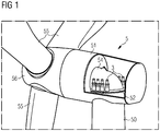
- Fig 1 shows a cutaway view into a nacelle of a direct-drive wind turbine 5.
- the diagram shows the nacelle 51 mounted on a tower 50.
- An aerodynamic rotor 55, 56 at the front of the nacelle comprises rotor blades 55 mounted to a hub 56, which turns the rotor of a generator.
- the generator (not visible in the diagram) is mounted to a support structure 54.
- a toothed yaw ring is mounted to the tower, and a several yaw drive units 3 are arranged so that their pinions engage with the teeth of the yaw ring.
- the yaw drive units 3 are securely held in place by a yaw bedframe 52, which can be part of the support structure 54.
- a yaw bedframe 52 which can be part of the support structure 54.
- Fig 2 shows a side view of a yaw assembly of the type described in Fig 1 , showing the arrangement of the yaw drive units 3 in more detail.
- the diagram also shows the yaw ring 2, which is mounted close to the top of the tower on the outside.
- Each motor 3 has a pinion 30 which is mounted on a shaft that extends through a yaw bedframe 52, and the body of the yaw drive unit 3 is secured to the bedframe 52.
- the yaw bedframe 52 is securely mounted to the bedframe 54.
- Each yaw drive unit 3 further comprises a motor 31, a gearbox 32, and a brake 33.
- the yaw drive motors 31 are electrically powered.
- a controller (also not shown) actuates the yaw drive motors to turn the pinions either clockwise or counter-clockwise, depending on the direction in which the nacelle is to be rotated.
- the controller also determines the speed of rotation of the pinions 30, and the pinion torque.
- the forces applied by the pinion teeth to the yaw ring teeth can be quite large, depending on the wind conditions, the speed, extent and frequency of turning procedures, etc.
- the teeth of the yaw ring 2 and the teeth of the pinions 30 are therefore subject to wear and tear during operation of the wind turbine. A tooth can fracture, crack or even break off entirely at some point.
- a fractured or broken tooth may be detected during a visual inspection of the yaw assembly, or may be detected by a controller of the yaw drive units. While it is possible to replace a yaw drive unit 3 with relatively little effort, replacement of the yaw ring 2 is a very expensive operation.
- Fig 3 shows a schematic representation of an embodiment of the inventive wind turbine yaw assembly 1.
- the diagram shows an outer yaw ring 2 mounted to a tower 50, and an arrangement of yaw drive units 3, in two groups of four.
- the yaw drive units 3 are held in place by a yaw bedframe 52, which rotates as one with the nacelle (not shown), and may be assumed to have the same design illustrated in Fig 1 and Fig 2 above.
- the yaw ring 2 is stationary, and the entire nacelle (with yaw bedframe and yaw assembly) rotates relative to the stationary yaw ring 2.
- the number of teeth on the yaw ring will depend to some extent on the diameter of the yaw ring.
- a controller 10 keeps track of the positions of the yaw drive units 3.
- the controller 10 is configured to track the position of each yaw drive unit 3 relative to a reference. For example, a specific initial configuration may be given when a reference point R 2 of the yaw ring 2 is aligned with a reference point R 52 of the bedframe 52.
- the invention deploys a suitable algorithm to track the yaw drive units 3, so that the controller 10 can always "know" the position of each yaw drive unit 3 relative to the reference point R 2 on the yaw ring 2.
- the controller 10 is also provided with a damage descriptor for any damaged tooth, particularly for any damaged tooth of the yaw ring 2.
- the diagram shows two such damaged teeth 20 F , 20 X : a fractured tooth 20 F and a broken tooth 20 X (in the circled regions of the yaw ring 2).
- the damaged teeth 20 F , 20 X may have been detected during a visual inspection of the yaw assembly, or may have been detected by the controller 10 if this is configured to interpret feedback from the yaw drive units 3.
- the position of each damaged tooth is expressed relative to the reference point R 2 of the yaw ring 2.
- the inventive method even allows the controller 10 to "know" which tooth of a pinion is engaging with a specific tooth of the yaw ring 2. With this precise tracking information, the controller 10 can issue appropriate control signals to each individual yaw drive unit 3 as necessary in order to minimize the force applied by its pinion to a damaged yaw ring tooth.
- a damaged tooth 20 F , 20 X may be defined by its angular positon ⁇ 20F , ⁇ 20X relative to the reference point R 2 .
- the position of a damaged tooth 20 F , 20 X may be its count number relative to a reference point R 52 of the bedframe 52. For example, if the tooth at the reference point R 52 is given the number 0, the position of the damaged tooth 20 F in this exemplary embodiment would be the number 10.
- the damage descriptor D 20F , D 20X for a damaged tooth simply comprises the position of the damaged tooth
- the controller 10 can be configured to control the yaw drive units 3 so that none of the yaw drive units exert any force on the damaged tooth during a rotation of the yaw ring, or when the yaw drive units are being used to "park" the nacelle in a specific position.
- the extent or severity of the damage may also be input to the controller 10 by means of a suitable user interface 11.
- a number between one and five may define the severity of the damage, with "one" indicating a slight fracture and "five" indicating a missing or broken tooth.
- the damage descriptor D 20F , D 20X for a damaged tooth comprises the position of the damaged tooth as well as a number indicating the severity of the damage.
- the controller 10 can be configured to control the yaw drive units 3 so that, whenever the damaged tooth is passing a yaw drive unit, the relevant yaw drive unit only exerts a force that can be safely withstood by the damaged tooth.
- the controller 10 may control the yaw drive units 3 as appropriate to only exert a fraction of full torque on the damaged tooth when the damage is classified as "three" or less, and to not apply any force to that tooth when the damage is classified as "four" or greater.
- Fig 4 shows the effect of the inventive method of operating a wind turbine yaw assembly.
- the diagram shows (greatly simplified) a yaw ring 2, the pinions 30 of two yaw drive units, and a controller 10.
- the controller 10 has received a damage descriptor D 20F for a fractured yaw ring tooth 20 F .
- the controller 10 tracks the positon of each yaw drive unit and pinion relative to each tooth of the yaw ring 2. As long as a pinion does not pass a damaged tooth, the controller 10 will control the relevant yaw drive unit(s) at the speed and torque required to carry out the desired rotation.
- Fig 5 shows an example of the force applied by a pinion of a yaw drive unit to the teeth of a yaw ring as the pinion passes a damaged tooth, in an embodiment of the inventive method.
- the yaw drive controller has previously been informed of the presence of a damaged tooth, and "knows" that the damaged tooth is in a region R of the yaw ring.
- the yawing procedure is to turn the nacelle through a certain number of degrees, represented by the ⁇ 1 - ⁇ 2 span along the X axis.
- the yaw drive controller issues appropriate control signals to the yaw drive motors so that, as a pinion passes healthy teeth, the pinion exerts full force F max to the healthy teeth, but as a pinion passes the damaged tooth, it will only exert a negligible force F min to the damaged tooth.
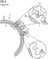
- Fig 6 shows the effect of a prior art method of operating a wind turbine yaw assembly.
- the diagram shows (greatly simplified) a yaw ring 2 and the pinions 30 of three yaw drive units.
- a controller (not shown) is operating the yaw drive unit(s) at the speed and torque required to carry out a desired rotation (indicated by the rotation arrows).
- a pinion passes a fractured tooth 20 F
- the full force F exerted by the pinion will stress the fractured tooth 20 F even further, as shown in the upper left enlarged view.
- the fractured tooth 20 F may ultimately break off entirely and become a broken tooth 20 X , as shown in the lower right enlarged view.
- a fractured tooth could be repaired by welding, and a broken tooth might be repaired by welding a replacement tooth onto the yaw ring or by securing a suitably shaped plate into place on the yaw ring.
- a repaired tooth is a weak element, and the prior art approach of operating the yaw drive assembly in the usual manner means that the loads applied by the pinions will ultimately cause the repaired tooth to fail again, so that replacement of the yaw ring becomes inevitable.
- the inventive idea could find use in a rotor blade pitch system which uses a toothed pitch ring and a motor-driven pinion to pitch the rotor blade.
- the yaw drive motors may be constructed using stepper motors. In the case of a broken-off tooth, a yaw drive unit would be controlled to make its pinion rotate at the normal speed, so that poor meshing does not become a problem.
Claims (15)
- Procédé d'exploitation d'un ensemble d'orientation d'éolienne (1) comprenant une couronne d'orientation (2) et un certain nombre d'unités d'entraînement d'orientation (3), dans lequel une unité d'entraînement d'orientation (3) comprend un pignon (30) conçu pour venir en prise avec la couronne d'orientation (2), lequel procédé est caractérisé par les étapes de- l'identification d'une dent endommagée (20F, 20X) sur la couronne d'orientation (2) ;- la fourniture de paramètres de descripteur d'endommagement (D20F, D20X) au contrôleur d'entraînement d'orientation (10) ; et- la commande d'une unité d'entraînement d'orientation (3) sur la base des paramètres de descripteur d'endommagement (D20F, D20X) pour réduire la force exercée par son pignon (30) sur une dent endommagée (20F, 20X).
- Procédé selon la revendication 1, dans lequel l'étape de commande d'une unité d'entraînement d'orientation (3) pour réduire la force exercée par son pignon (30) sur la dent endommagée (20F, 20X) comprend la réduction de la vitesse de rotation d'un moteur (31) de l'unité d'entraînement d'orientation (3).
- Procédé selon la revendication 1 ou la revendication 2, dans lequel l'étape de commande d'une unité d'entraînement d'orientation (3) pour réduire la force exercée par son pignon (30) sur la dent endommagée (20F, 20X) comprend la réduction du couple du moteur (31) de cette unité d'entraînement d'orientation (3) jusqu'à 5 % au plus, plus préférentiellement 1 % au plus, du couple maximal (F).
- Procédé selon l'une quelconque des revendications précédentes, dans lequel l'étape de réduction de la force exercée par un pignon (30) sur une dent endommagée (20F, 20X) est effectuée pendant une procédure d'orientation de la nacelle et/ou pendant une procédure de freinage.
- Procédé selon l'une quelconque des revendications précédentes, dans lequel l'étape d'identification d'une dent endommagée (20F, 20X) comprend l'établissement de la position d'une dent endommagée (20F, 20X) par rapport à une position de référence (R2, R52) de l'ensemble d'orientation (1).
- Procédé selon la revendication 5, dans lequel une position de référence (R52) définit une position initiale d'un châssis berceau d'orientation (52) portant les unités d'entraînement d'orientation (3).
- Procédé selon la revendication 5 ou la revendication 6, dans lequel la position de référence (R2) comprend une référence nord (R2) de la couronne d'orientation (2), laquelle référence nord (R2) est alignée avec la position de référence de châssis berceau d'orientation (R52) dans une position initiale de l'ensemble d'orientation (1).
- Procédé selon l'une quelconque des revendications précédentes, dans lequel l'étape d'identification d'une dent endommagée (20F, 20X) comprend l'établissement d'un paramètre de sévérité d'endommagement décrivant l'étendue d'endommagement de la dent endommagée (20F, 20X) .
- Ensemble d'orientation d'éolienne (1) agencé à une interface entre une nacelle (51) et une tour (50) d'une éolienne (5), et comprenant- une couronne d'orientation (2) ayant un agencement annulaire de dents (20) ;- un certain nombre d'unités d'entraînement d'orientation (3), dans lequel une unité d'entraînement d'orientation (3) comprend un moteur (31) et un pignon (30) conçu pour venir en prise avec les dents (20) de la couronne d'orientation (2) ;- un contrôleur d'entraînement d'orientation (10) conçu pour commander le moteur (31) d'une unité d'entraînement d'orientation (3) pour effectuer une rotation de la nacelle (51) par rapport à la tour (50) ;
caractérisé par
une entrée de descripteur d'endommagement pour la fourniture de paramètres de descripteur d'endommagement (D20F, D20X) au contrôleur d'entraînement d'orientation (10) et dans lequel le contrôleur d'entraînement d'orientation (10) est en outre conçu pour réduire la force exercée par un pignon (30) d'une unité d'entraînement d'orientation (3) sur une dent endommagée (20F, 20X) sur la base des paramètres de descripteur d'endommagement (D20F, D20X). - Ensemble d'orientation d'éolienne selon la revendication 9, comprenant un agencement redondant d'unités d'entraînement d'orientation (3).
- Ensemble d'orientation d'éolienne selon la revendication 9 ou la revendication 10, dans lequel une unité d'entraînement d'orientation (3) comprend un ensemble de frein passif (33).
- Éolienne (5) comprenant un ensemble d'orientation (1) selon l'une quelconque des revendications 9 à 11.
- Produit de programme informatique comprenant un programme informatique qui est apte à être directement chargé dans une mémoire d'un contrôleur (10) d'un ensemble d'orientation d'éolienne (1) et qui comprend des éléments de programme conçus pour effectuer les étapes du procédé selon l'une quelconque des revendications 1 à 8 lorsque le programme informatique est exécuté par le contrôleur (10) de l'ensemble d'orientation d'éolienne (1).
- Produit de programme informatique selon la revendication 13, comprenant des éléments de programme réalisés pour recevoir un paramètre de sévérité d'endommagement (S20F, S20X) et pour régler les signaux de commande d'une unité d'entraînement d'orientation (3) sur la base du paramètre de sévérité d'endommagement (S20F, S20X).
- Produit de programme informatique selon la revendication 13 ou la revendication 14, comprenant des éléments de programme réalisés pour identifier une région de couronne d'orientation contenant une dent endommagée (20F, 20X) et pour régler des signaux de commande d'une unité d'entraînement d'orientation (3) lorsque l'unité d'entraînement d'orientation (3) passe cette région de la couronne d'orientation (2).
Priority Applications (5)
| Application Number | Priority Date | Filing Date | Title |
|---|---|---|---|
| ES17189234T ES2812277T3 (es) | 2017-09-04 | 2017-09-04 | Procedimiento de funcionamiento de un conjunto de guiñada de turbina eólica |
| EP17189234.2A EP3450745B1 (fr) | 2017-09-04 | 2017-09-04 | Procédé d'exploitation d'un ensemble en lacet d'une éolienne |
| DK17189234.2T DK3450745T3 (da) | 2017-09-04 | 2017-09-04 | Fremgangsmåde til drift af en vindmøllekrøjningsenhed |
| US16/112,862 US10634119B2 (en) | 2017-09-04 | 2018-08-27 | Method of operating a wind turbine yaw assembly |
| CN201811026271.9A CN109424497B (zh) | 2017-09-04 | 2018-09-04 | 操作风力涡轮机偏转组件的方法 |
Applications Claiming Priority (1)
| Application Number | Priority Date | Filing Date | Title |
|---|---|---|---|
| EP17189234.2A EP3450745B1 (fr) | 2017-09-04 | 2017-09-04 | Procédé d'exploitation d'un ensemble en lacet d'une éolienne |
Publications (2)
| Publication Number | Publication Date |
|---|---|
| EP3450745A1 EP3450745A1 (fr) | 2019-03-06 |
| EP3450745B1 true EP3450745B1 (fr) | 2020-07-01 |
Family
ID=59772519
Family Applications (1)
| Application Number | Title | Priority Date | Filing Date |
|---|---|---|---|
| EP17189234.2A Active EP3450745B1 (fr) | 2017-09-04 | 2017-09-04 | Procédé d'exploitation d'un ensemble en lacet d'une éolienne |
Country Status (5)
| Country | Link |
|---|---|
| US (1) | US10634119B2 (fr) |
| EP (1) | EP3450745B1 (fr) |
| CN (1) | CN109424497B (fr) |
| DK (1) | DK3450745T3 (fr) |
| ES (1) | ES2812277T3 (fr) |
Families Citing this family (2)
| Publication number | Priority date | Publication date | Assignee | Title |
|---|---|---|---|---|
| WO2020098896A1 (fr) * | 2018-11-15 | 2020-05-22 | Vestas Wind Systems A/S | Agencement de lacet pour éolienne à rotors multiples |
| JP2021174114A (ja) * | 2020-04-21 | 2021-11-01 | ナブテスコ株式会社 | 状態監視装置及び状態監視方法 |
Family Cites Families (20)
| Publication number | Priority date | Publication date | Assignee | Title |
|---|---|---|---|---|
| EP1571334A1 (fr) * | 2004-03-04 | 2005-09-07 | Gamesa Eolica, S.A. (Sociedad Unipersonal) | Dispositif et procédé de maintien d'une éolienne orientable dans la direction du vent |
| DE112008000344B4 (de) * | 2007-02-05 | 2021-11-25 | Sumitomo Heavy Industries, Ltd. | Leistungsübertragungsvorrichtung und Herstellungsverfahren dafür |
| JP5284872B2 (ja) * | 2009-05-22 | 2013-09-11 | 株式会社日立製作所 | 水平軸風車 |
| EP2549099B1 (fr) * | 2009-06-30 | 2015-10-21 | Vestas Wind Systems A/S | Éolienne avec contrôle de lacet amélioré |
| DK2345749T3 (en) * | 2010-01-14 | 2016-02-29 | Siemens Ag | Gear unit and wind turbine |
| JP5562274B2 (ja) | 2010-03-12 | 2014-07-30 | Ntn株式会社 | 摩耗検知装置およびそれを備える風力発電装置ならびに摩耗検知方法 |
| US9869298B2 (en) * | 2010-06-29 | 2018-01-16 | Vestas Wind Systems A/S | Rotational positioning system in a wind turbine |
| DE102011101140A1 (de) * | 2011-05-11 | 2012-11-15 | Robert Bosch Gmbh | Getriebe, Windenergieanlage und Verfahren zur Herstellung eines Getriebes |
| US10202964B2 (en) * | 2011-07-04 | 2019-02-12 | Vestas Wind Systems A/S | Method of yawing a rotor of a wind turbine |
| EP2708738A1 (fr) | 2012-09-12 | 2014-03-19 | Alstom Wind, S.L.U. | Éolienne |
| JP2015533999A (ja) * | 2012-11-09 | 2015-11-26 | ヴェスタス ウィンド システムズ エー/エス | 風力タービンヨー制御システム |
| DK2837818T3 (en) | 2013-08-13 | 2019-03-11 | Siemens Ag | Wind turbine with bend bearing lift device |
| JP6138012B2 (ja) | 2013-09-27 | 2017-05-31 | 住友重機械工業株式会社 | 風力発電設備のヨー駆動システム |
| JP2016011590A (ja) * | 2014-06-27 | 2016-01-21 | ナブテスコ株式会社 | 風車用回転駆動機構 |
| AU2015335363B2 (en) * | 2014-10-24 | 2019-02-14 | Vestas Wind Systems A/S | Repairing a gear part in a wind turbine |
| US9951818B2 (en) * | 2015-05-13 | 2018-04-24 | Wind Solutions, LLC. | Wind turbine yaw bearing pre-load |
| ES2812808T3 (es) * | 2016-02-12 | 2021-03-18 | Vestas Wind Sys As | Mejoras en relación con un sensor de guiñada para una turbina eólica |
| ES2767823T3 (es) * | 2017-03-21 | 2020-06-18 | Nordex Energy Gmbh | Unión giratoria de un aerogenerador y dentado para una unión giratoria |
| US10876517B2 (en) * | 2017-12-22 | 2020-12-29 | Wind Solutions, Llc | Slew ring repair and damage prevention |
| US11060503B2 (en) * | 2018-03-13 | 2021-07-13 | Wind Solutions, Llc | Yaw pad engagement features |
-
2017
- 2017-09-04 EP EP17189234.2A patent/EP3450745B1/fr active Active
- 2017-09-04 DK DK17189234.2T patent/DK3450745T3/da active
- 2017-09-04 ES ES17189234T patent/ES2812277T3/es active Active
-
2018
- 2018-08-27 US US16/112,862 patent/US10634119B2/en active Active
- 2018-09-04 CN CN201811026271.9A patent/CN109424497B/zh active Active
Non-Patent Citations (1)
| Title |
|---|
| None * |
Also Published As
| Publication number | Publication date |
|---|---|
| CN109424497A (zh) | 2019-03-05 |
| EP3450745A1 (fr) | 2019-03-06 |
| US10634119B2 (en) | 2020-04-28 |
| DK3450745T3 (da) | 2020-08-31 |
| ES2812277T3 (es) | 2021-03-16 |
| CN109424497B (zh) | 2020-10-23 |
| US20190072074A1 (en) | 2019-03-07 |
Similar Documents
| Publication | Publication Date | Title |
|---|---|---|
| US8279073B2 (en) | Systems, methods, and apparatus for monitoring and controlling a wind driven machine | |
| EP2588751B1 (fr) | Système de positionnement en rotation dans une éolienne | |
| EP2440780B1 (fr) | Unité de commande pour centrale éolienne permettant d'éviter la défaillance d'origine commune | |
| DK2418380T3 (en) | Blade angle control device for wind turbine. | |
| DK2352918T3 (en) | Device for adjusting a rotor blade, wind energy converter, and method for setting a rotor blade | |
| EP2638281B1 (fr) | Procédé et système pour faire fonctionner une turbine éolienne pendant une défaillance | |
| EP2859224B1 (fr) | Commande de turbine éolienne | |
| CN103270293A (zh) | 风力涡轮机转子 | |
| JP6847118B2 (ja) | 風力発電設備 | |
| EP3663573B1 (fr) | Procédé pour réduire les vibrations dans des pales de rotor d'une éolienne | |
| EP3450745B1 (fr) | Procédé d'exploitation d'un ensemble en lacet d'une éolienne | |
| EP3553310B1 (fr) | Système d'entraînement d'un moulin à vent et moulin à vent | |
| US20230014873A1 (en) | Yaw supervision | |
| US7235996B2 (en) | Functionality test method | |
| EP3721079B1 (fr) | Procédé pour régler l'angle de pas de pales de turbine éolienne | |
| EP4332374A1 (fr) | Système et procédé de détection et de réponse à un endommagement de pale de rotor dans une éolienne | |
| EP4361434A1 (fr) | Protection de composants d'éolienne pendant le lacet | |
| US20240133360A1 (en) | Protection of wind turbine components during yawing | |
| CN105004522A (zh) | 基于光信号的风机轴系故障诊断和状态监测系统 |
Legal Events
| Date | Code | Title | Description |
|---|---|---|---|
| PUAI | Public reference made under article 153(3) epc to a published international application that has entered the european phase |
Free format text: ORIGINAL CODE: 0009012 |
|
| STAA | Information on the status of an ep patent application or granted ep patent |
Free format text: STATUS: THE APPLICATION HAS BEEN PUBLISHED |
|
| AK | Designated contracting states |
Kind code of ref document: A1 Designated state(s): AL AT BE BG CH CY CZ DE DK EE ES FI FR GB GR HR HU IE IS IT LI LT LU LV MC MK MT NL NO PL PT RO RS SE SI SK SM TR |
|
| AX | Request for extension of the european patent |
Extension state: BA ME |
|
| STAA | Information on the status of an ep patent application or granted ep patent |
Free format text: STATUS: REQUEST FOR EXAMINATION WAS MADE |
|
| 17P | Request for examination filed |
Effective date: 20190903 |
|
| RBV | Designated contracting states (corrected) |
Designated state(s): AL AT BE BG CH CY CZ DE DK EE ES FI FR GB GR HR HU IE IS IT LI LT LU LV MC MK MT NL NO PL PT RO RS SE SI SK SM TR |
|
| GRAP | Despatch of communication of intention to grant a patent |
Free format text: ORIGINAL CODE: EPIDOSNIGR1 |
|
| STAA | Information on the status of an ep patent application or granted ep patent |
Free format text: STATUS: GRANT OF PATENT IS INTENDED |
|
| INTG | Intention to grant announced |
Effective date: 20200212 |
|
| GRAS | Grant fee paid |
Free format text: ORIGINAL CODE: EPIDOSNIGR3 |
|
| GRAA | (expected) grant |
Free format text: ORIGINAL CODE: 0009210 |
|
| STAA | Information on the status of an ep patent application or granted ep patent |
Free format text: STATUS: THE PATENT HAS BEEN GRANTED |
|
| AK | Designated contracting states |
Kind code of ref document: B1 Designated state(s): AL AT BE BG CH CY CZ DE DK EE ES FI FR GB GR HR HU IE IS IT LI LT LU LV MC MK MT NL NO PL PT RO RS SE SI SK SM TR |
|
| REG | Reference to a national code |
Ref country code: CH Ref legal event code: EP Ref country code: AT Ref legal event code: REF Ref document number: 1286417 Country of ref document: AT Kind code of ref document: T Effective date: 20200715 |
|
| REG | Reference to a national code |
Ref country code: IE Ref legal event code: FG4D |
|
| REG | Reference to a national code |
Ref country code: DE Ref legal event code: R096 Ref document number: 602017018921 Country of ref document: DE |
|
| REG | Reference to a national code |
Ref country code: DK Ref legal event code: T3 Effective date: 20200826 |
|
| REG | Reference to a national code |
Ref country code: NL Ref legal event code: FP |
|
| REG | Reference to a national code |
Ref country code: LT Ref legal event code: MG4D |
|
| PG25 | Lapsed in a contracting state [announced via postgrant information from national office to epo] |
Ref country code: BG Free format text: LAPSE BECAUSE OF FAILURE TO SUBMIT A TRANSLATION OF THE DESCRIPTION OR TO PAY THE FEE WITHIN THE PRESCRIBED TIME-LIMIT Effective date: 20201001 |
|
| REG | Reference to a national code |
Ref country code: AT Ref legal event code: MK05 Ref document number: 1286417 Country of ref document: AT Kind code of ref document: T Effective date: 20200701 |
|
| PG25 | Lapsed in a contracting state [announced via postgrant information from national office to epo] |
Ref country code: CZ Free format text: LAPSE BECAUSE OF FAILURE TO SUBMIT A TRANSLATION OF THE DESCRIPTION OR TO PAY THE FEE WITHIN THE PRESCRIBED TIME-LIMIT Effective date: 20200701 Ref country code: LT Free format text: LAPSE BECAUSE OF FAILURE TO SUBMIT A TRANSLATION OF THE DESCRIPTION OR TO PAY THE FEE WITHIN THE PRESCRIBED TIME-LIMIT Effective date: 20200701 Ref country code: AT Free format text: LAPSE BECAUSE OF FAILURE TO SUBMIT A TRANSLATION OF THE DESCRIPTION OR TO PAY THE FEE WITHIN THE PRESCRIBED TIME-LIMIT Effective date: 20200701 Ref country code: PT Free format text: LAPSE BECAUSE OF FAILURE TO SUBMIT A TRANSLATION OF THE DESCRIPTION OR TO PAY THE FEE WITHIN THE PRESCRIBED TIME-LIMIT Effective date: 20201102 Ref country code: HR Free format text: LAPSE BECAUSE OF FAILURE TO SUBMIT A TRANSLATION OF THE DESCRIPTION OR TO PAY THE FEE WITHIN THE PRESCRIBED TIME-LIMIT Effective date: 20200701 Ref country code: SE Free format text: LAPSE BECAUSE OF FAILURE TO SUBMIT A TRANSLATION OF THE DESCRIPTION OR TO PAY THE FEE WITHIN THE PRESCRIBED TIME-LIMIT Effective date: 20200701 Ref country code: FI Free format text: LAPSE BECAUSE OF FAILURE TO SUBMIT A TRANSLATION OF THE DESCRIPTION OR TO PAY THE FEE WITHIN THE PRESCRIBED TIME-LIMIT Effective date: 20200701 Ref country code: GR Free format text: LAPSE BECAUSE OF FAILURE TO SUBMIT A TRANSLATION OF THE DESCRIPTION OR TO PAY THE FEE WITHIN THE PRESCRIBED TIME-LIMIT Effective date: 20201002 Ref country code: NO Free format text: LAPSE BECAUSE OF FAILURE TO SUBMIT A TRANSLATION OF THE DESCRIPTION OR TO PAY THE FEE WITHIN THE PRESCRIBED TIME-LIMIT Effective date: 20201001 |
|
| PG25 | Lapsed in a contracting state [announced via postgrant information from national office to epo] |
Ref country code: RS Free format text: LAPSE BECAUSE OF FAILURE TO SUBMIT A TRANSLATION OF THE DESCRIPTION OR TO PAY THE FEE WITHIN THE PRESCRIBED TIME-LIMIT Effective date: 20200701 Ref country code: LV Free format text: LAPSE BECAUSE OF FAILURE TO SUBMIT A TRANSLATION OF THE DESCRIPTION OR TO PAY THE FEE WITHIN THE PRESCRIBED TIME-LIMIT Effective date: 20200701 Ref country code: PL Free format text: LAPSE BECAUSE OF FAILURE TO SUBMIT A TRANSLATION OF THE DESCRIPTION OR TO PAY THE FEE WITHIN THE PRESCRIBED TIME-LIMIT Effective date: 20200701 Ref country code: IS Free format text: LAPSE BECAUSE OF FAILURE TO SUBMIT A TRANSLATION OF THE DESCRIPTION OR TO PAY THE FEE WITHIN THE PRESCRIBED TIME-LIMIT Effective date: 20201101 |
|
| REG | Reference to a national code |
Ref country code: ES Ref legal event code: FG2A Ref document number: 2812277 Country of ref document: ES Kind code of ref document: T3 Effective date: 20210316 |
|
| REG | Reference to a national code |
Ref country code: DE Ref legal event code: R097 Ref document number: 602017018921 Country of ref document: DE |
|
| PG25 | Lapsed in a contracting state [announced via postgrant information from national office to epo] |
Ref country code: SM Free format text: LAPSE BECAUSE OF FAILURE TO SUBMIT A TRANSLATION OF THE DESCRIPTION OR TO PAY THE FEE WITHIN THE PRESCRIBED TIME-LIMIT Effective date: 20200701 Ref country code: IT Free format text: LAPSE BECAUSE OF FAILURE TO SUBMIT A TRANSLATION OF THE DESCRIPTION OR TO PAY THE FEE WITHIN THE PRESCRIBED TIME-LIMIT Effective date: 20200701 Ref country code: EE Free format text: LAPSE BECAUSE OF FAILURE TO SUBMIT A TRANSLATION OF THE DESCRIPTION OR TO PAY THE FEE WITHIN THE PRESCRIBED TIME-LIMIT Effective date: 20200701 Ref country code: RO Free format text: LAPSE BECAUSE OF FAILURE TO SUBMIT A TRANSLATION OF THE DESCRIPTION OR TO PAY THE FEE WITHIN THE PRESCRIBED TIME-LIMIT Effective date: 20200701 |
|
| REG | Reference to a national code |
Ref country code: CH Ref legal event code: PL |
|
| PLBE | No opposition filed within time limit |
Free format text: ORIGINAL CODE: 0009261 |
|
| STAA | Information on the status of an ep patent application or granted ep patent |
Free format text: STATUS: NO OPPOSITION FILED WITHIN TIME LIMIT |
|
| PG25 | Lapsed in a contracting state [announced via postgrant information from national office to epo] |
Ref country code: AL Free format text: LAPSE BECAUSE OF FAILURE TO SUBMIT A TRANSLATION OF THE DESCRIPTION OR TO PAY THE FEE WITHIN THE PRESCRIBED TIME-LIMIT Effective date: 20200701 |
|
| 26N | No opposition filed |
Effective date: 20210406 |
|
| REG | Reference to a national code |
Ref country code: BE Ref legal event code: MM Effective date: 20200930 |
|
| PG25 | Lapsed in a contracting state [announced via postgrant information from national office to epo] |
Ref country code: SK Free format text: LAPSE BECAUSE OF FAILURE TO SUBMIT A TRANSLATION OF THE DESCRIPTION OR TO PAY THE FEE WITHIN THE PRESCRIBED TIME-LIMIT Effective date: 20200701 Ref country code: LU Free format text: LAPSE BECAUSE OF NON-PAYMENT OF DUE FEES Effective date: 20200904 |
|
| PG25 | Lapsed in a contracting state [announced via postgrant information from national office to epo] |
Ref country code: SI Free format text: LAPSE BECAUSE OF FAILURE TO SUBMIT A TRANSLATION OF THE DESCRIPTION OR TO PAY THE FEE WITHIN THE PRESCRIBED TIME-LIMIT Effective date: 20200701 Ref country code: IE Free format text: LAPSE BECAUSE OF NON-PAYMENT OF DUE FEES Effective date: 20200904 Ref country code: LI Free format text: LAPSE BECAUSE OF NON-PAYMENT OF DUE FEES Effective date: 20200930 Ref country code: CH Free format text: LAPSE BECAUSE OF NON-PAYMENT OF DUE FEES Effective date: 20200930 Ref country code: BE Free format text: LAPSE BECAUSE OF NON-PAYMENT OF DUE FEES Effective date: 20200930 |
|
| PG25 | Lapsed in a contracting state [announced via postgrant information from national office to epo] |
Ref country code: TR Free format text: LAPSE BECAUSE OF FAILURE TO SUBMIT A TRANSLATION OF THE DESCRIPTION OR TO PAY THE FEE WITHIN THE PRESCRIBED TIME-LIMIT Effective date: 20200701 Ref country code: MT Free format text: LAPSE BECAUSE OF FAILURE TO SUBMIT A TRANSLATION OF THE DESCRIPTION OR TO PAY THE FEE WITHIN THE PRESCRIBED TIME-LIMIT Effective date: 20200701 Ref country code: CY Free format text: LAPSE BECAUSE OF FAILURE TO SUBMIT A TRANSLATION OF THE DESCRIPTION OR TO PAY THE FEE WITHIN THE PRESCRIBED TIME-LIMIT Effective date: 20200701 |
|
| PG25 | Lapsed in a contracting state [announced via postgrant information from national office to epo] |
Ref country code: MK Free format text: LAPSE BECAUSE OF FAILURE TO SUBMIT A TRANSLATION OF THE DESCRIPTION OR TO PAY THE FEE WITHIN THE PRESCRIBED TIME-LIMIT Effective date: 20200701 Ref country code: MC Free format text: LAPSE BECAUSE OF FAILURE TO SUBMIT A TRANSLATION OF THE DESCRIPTION OR TO PAY THE FEE WITHIN THE PRESCRIBED TIME-LIMIT Effective date: 20200701 |
|
| PGFP | Annual fee paid to national office [announced via postgrant information from national office to epo] |
Ref country code: NL Payment date: 20220922 Year of fee payment: 6 Ref country code: GB Payment date: 20220927 Year of fee payment: 6 Ref country code: DK Payment date: 20220926 Year of fee payment: 6 Ref country code: DE Payment date: 20220920 Year of fee payment: 6 |
|
| PGFP | Annual fee paid to national office [announced via postgrant information from national office to epo] |
Ref country code: FR Payment date: 20220921 Year of fee payment: 6 |
|
| PGFP | Annual fee paid to national office [announced via postgrant information from national office to epo] |
Ref country code: ES Payment date: 20221018 Year of fee payment: 6 |
|
| REG | Reference to a national code |
Ref country code: DK Ref legal event code: EBP Effective date: 20230930 |