EP3450720A2 - Switching valve for controlling a hydraulic fluid stream and connecting rod for a combustion engine with variable compression with a switching valve - Google Patents
Switching valve for controlling a hydraulic fluid stream and connecting rod for a combustion engine with variable compression with a switching valve Download PDFInfo
- Publication number
- EP3450720A2 EP3450720A2 EP18189918.8A EP18189918A EP3450720A2 EP 3450720 A2 EP3450720 A2 EP 3450720A2 EP 18189918 A EP18189918 A EP 18189918A EP 3450720 A2 EP3450720 A2 EP 3450720A2
- Authority
- EP
- European Patent Office
- Prior art keywords
- connecting rod
- valve
- latching
- valve housing
- switching
- Prior art date
- Legal status (The legal status is an assumption and is not a legal conclusion. Google has not performed a legal analysis and makes no representation as to the accuracy of the status listed.)
- Withdrawn
Links
Images


Classifications
-
- F—MECHANICAL ENGINEERING; LIGHTING; HEATING; WEAPONS; BLASTING
- F02—COMBUSTION ENGINES; HOT-GAS OR COMBUSTION-PRODUCT ENGINE PLANTS
- F02B—INTERNAL-COMBUSTION PISTON ENGINES; COMBUSTION ENGINES IN GENERAL
- F02B75/00—Other engines
- F02B75/04—Engines with variable distances between pistons at top dead-centre positions and cylinder heads
- F02B75/045—Engines with variable distances between pistons at top dead-centre positions and cylinder heads by means of a variable connecting rod length
Landscapes
- Engineering & Computer Science (AREA)
- Chemical & Material Sciences (AREA)
- Combustion & Propulsion (AREA)
- Mechanical Engineering (AREA)
- General Engineering & Computer Science (AREA)
- Shafts, Cranks, Connecting Bars, And Related Bearings (AREA)
- Multiple-Way Valves (AREA)
- Output Control And Ontrol Of Special Type Engine (AREA)
Abstract
Die Erfindung betrifft ein Umschaltventil (11) zum Steuern eines Hydraulikflüssigkeitsstroms, mit einem in einem Ventilgehäuse (12) angeordneten Abgriffselement (13), welches wahlweise in eine erste Schaltstellung (S1) oder eine zweite Schaltstellung (S2) verlagerbar und mittels eines federelementbeaufschlagten Rastelementes (14) wahlweise in der ersten oder der zweiten Schaltstellung (S1, S2) arretierbar ist. In der ersten Schaltstellung (S1) ist ein erster Hydraulikanschluss (22) mit einem Entlastungsanschluss (26) und in der zweiten Schaltstellung (S2) ein zweiter Hydraulikanschluss (24) mit dem Entlastungsanschluss (26) verbunden, wobei ein Schaltweg des Abgriffselements (13) begrenzt vorgesehen ist. Das Ventilgehäuse (12) weist in einer axialen Richtung (L) eine axial begrenzte erste Nut (17) auf, in welcher das Rastelement (14) mit dem Abgriffselement (13) axial verschiebbar angeordnet ist. Das Rastelement (14) wirkt mit einem Rastpin (18) zusammen, welcher im Ventilgehäuse (12) im Bereich der ersten Nut (17) angeordnet ist.The invention relates to a changeover valve (11) for controlling a hydraulic fluid flow, having a tapping element (13) arranged in a valve housing (12), which is displaceable either into a first switching position (S1) or a second switching position (S2) and by means of a catch element (spring elementbeaufschlagten). 14) optionally in the first or the second switching position (S1, S2) can be locked. In the first switching position (S1), a first hydraulic connection (22) is connected to a discharge connection (26) and in the second switching position (S2) a second hydraulic connection (24) is connected to the discharge connection (26), wherein a switching path of the tapping element (13) is provided limited. The valve housing (12) has an axially limited first groove (17) in an axial direction (L), in which the latching element (14) with the tapping element (13) is arranged to be axially displaceable. The latching element (14) cooperates with a latching pin (18), which is arranged in the valve housing (12) in the region of the first groove (17).
Die Erfindung betrifft ferner einen Pleuel (1) mit einem Umschaltventil (11).

Description
Die Erfindung betrifft ein Umschaltventil zum Steuern eines Hydraulikflüssigkeitsstroms, insbesondere für einen Pleuel für eine Brennkraftmaschine mit variabler Verdichtung mit einer Exzenter-Verstelleinrichtung zur Verstellung einer effektiven Pleuelstangenlänge. Ferner betrifft die Erfindung einen Pleuel mit einem derartigen Umschaltventil.The invention relates to a switching valve for controlling a hydraulic fluid flow, in particular for a connecting rod for an internal combustion engine with variable compression with an eccentric adjusting device for adjusting an effective connecting rod length. Furthermore, the invention relates to a connecting rod with such a switching valve.
Bei Brennkraftmaschinen wirkt sich ein hohes Verdichtungsverhältnis positiv auf den Wirkungsgrad des Verbrennungsmotors aus. Unter Verdichtungsverhältnis wird im Allgemeinen das Verhältnis des gesamten Zylinderraumes vor der Verdichtung zum verbliebenen Zylinderraum nach der Verdichtung verstanden. Bei Brennkraftmaschinen mit Fremdzündung, insbesondere Ottomotoren, die ein festes Verdichtungsverhältnis aufweisen, darf das Verdichtungsverhältnis jedoch nur so hoch gewählt werden, dass bei Volllastbetrieb ein sogenanntes "Klopfen" der Brennkraftmaschine vermieden wird. Jedoch könnte für den weitaus häufiger auftretenden Teillastbereich der Brennkraftmaschine, also bei geringer Zylinderfüllung, das Verdichtungsverhältnis mit höheren Werten gewählt werden, ohne dass ein "Klopfen" auftreten würde. Der wichtige Teillastbereich einer Brennkraftmaschine kann verbessert werden, wenn das Verdichtungsverhältnis variabel einstellbar ist. Zur Verstellung des Verdichtungsverhältnisses sind beispielsweise Systeme mit variabler Pleuelstangenlänge bekannt, welche mit Hilfe von hydraulisch oder mechanisch betätigbaren Umschaltventilen eine Exzenter-Verstelleinrichtung eines Pleuels betätigen.In internal combustion engines, a high compression ratio has a positive effect on the efficiency of the internal combustion engine. Under compression ratio is generally understood the ratio of the entire cylinder space before compression to the remaining cylinder space after compression. In internal combustion engines with spark ignition, in particular gasoline engines, which have a fixed compression ratio, the compression ratio, however, may only be selected so high that a so-called "knocking" of the internal combustion engine is avoided during full load operation. However, for the far more frequently occurring partial load range of the internal combustion engine, ie at lower Cylinder filling, the compression ratio with higher values are selected without a "knocking" would occur. The important part load range of an internal combustion engine can be improved if the compression ratio is variably adjustable. To adjust the compression ratio, systems with variable connecting rod length are known, for example, which actuate an eccentric adjustment of a connecting rod with the aid of hydraulically or mechanically operated changeover valves.
Ein gattungsgemäßes Umschaltventil ist beispielsweise aus der
Eine Aufgabe der Erfindung ist es, ein dahingehend verbessertes Umschaltventil zu schaffen.An object of the invention is to provide an improved switching valve.
Eine weitere Aufgabe ist es, einen Pleuel mit einem verbesserten Umschaltventil zu schaffen.Another object is to provide a connecting rod with an improved change-over valve.
Die vorgenannten Aufgaben werden mit den Merkmalen der unabhängigen Ansprüche gelöst.The above objects are achieved with the features of the independent claims.
Günstige Ausgestaltungen und Vorteile der Erfindung ergeben sich aus den weiteren Ansprüchen, der Beschreibung und der Zeichnung.Favorable embodiments and advantages of the invention will become apparent from the other claims, the description and the drawings.
Nach einem Aspekt der Erfindung wird ein Umschaltventil zum Steuern eines Hydraulikflüssigkeitsstroms vorgeschlagen, mit einem in einem Ventilgehäuse angeordneten Abgriffselement, welches wahlweise in eine erste Schaltstellung oder eine zweite Schaltstellung verlagerbar und mittels eines federelementbeaufschlagten Rastelementes wahlweise in der ersten oder der zweiten Schaltstellung arretierbar ist. Dabei ist in der ersten Schaltstellung ein erster Hydraulikanschluss mit einem Entlastungsanschluss und in der zweiten Schaltstellung ein zweiter Hydraulikanschluss mit dem Entlastungsanschluss verbunden, wobei ein Schaltweg des Abgriffselements begrenzt vorgesehen ist. Das Rastelement ist wenigstens teilweise in einer Ausnehmung des Abgriffselements angeordnet. Das Ventilgehäuse weist in einer axialen Richtung eine axial begrenzte erste Nut auf, in welcher das Rastelement mit dem Abgriffselement axial verschiebbar angeordnet ist. Dabei wirkt das Rastelement mit einem Rastpin zusammen, welcher im Ventilgehäuse im Bereich der ersten Nut angeordnet ist.According to one aspect of the invention, a switching valve for controlling a hydraulic fluid flow is proposed, with one in a valve housing arranged tapping element which is displaceable either in a first switching position or a second switching position displaceable and by means of a Federelementbeaufschlagten locking element optionally in the first or the second switching position can be locked. Here, in the first switching position, a first hydraulic connection with a discharge connection and in the second switching position, a second hydraulic connection connected to the discharge connection, wherein a switching path of the tap element is provided limited. The latching element is at least partially disposed in a recess of the tapping element. The valve housing has an axially limited first groove in an axial direction, in which the latching element is arranged axially displaceably with the tapping element. In this case, the latching element cooperates with a latching pin, which is arranged in the valve housing in the region of the first groove.
Das erfindungsgemäße Umschaltventil lässt sich sowohl hinsichtlich Konstruktion als auch hinsichtlich Herstellung und Kosten günstig gestalten. Das federbeaufschlagte Rastelement läuft vorteilhaft nicht mehr in dem Ventilgehäuse, sondern im Abgriffselement selbst. Somit ist das Federelement in seiner Länge durch das Rastelement und das Abgriffselement bestimmt. Eine aufwendige Rastkontur ist nicht nötig, sondern kann durch einen eingepressten Zylinderstift im Ventilgehäuse ersetzt werden, welcher zweckmäßigerweise senkrecht zur Einpressrichtung des Umschaltventils angeordnet ist. Es ist nur noch eine genaue Bohrung im Ventilgehäuse nötig. Ein Anschlagstift entfällt, da das Rastelement selbst als Anschlag dienen kann.The switching valve according to the invention can be made favorable both in terms of construction and in terms of production and costs. The spring-loaded detent element advantageously no longer runs in the valve housing, but in the tapping element itself. Thus, the spring element is determined in its length by the detent element and the tapping element. An elaborate locking contour is not necessary, but can be replaced by a pressed-cylindrical pin in the valve housing, which is suitably arranged perpendicular to the press-in direction of the changeover valve. There is only one exact hole in the valve body needed. A stop pin deleted because the locking element itself can serve as a stop.
Die erfindungsgemäße Ausführung des Umschaltventils erweist sich als vorteilhaft gegenüber dem Stand der Technik, bei dem es üblich ist, ein Umschaltventil in eine parallel zu Pleuelaugen eingebrachte Bohrung im Pleuel einzupressen. Der Pressverband dichtet dabei außenliegende Nuten und Bohrungen am Umschaltventil zueinander ab und verhindert einen hydraulischen Kurzschluss. Außerdem sichert der Pressverband das Umschaltventil gegen Herausfallen in Axialrichtung. Der Pressverband muss dabei so ausgelegt werden, dass bei allen Toleranzen immer eine genügend große Einpresskraft vorhanden ist, wobei die Einpresskraft ungefähr gleich der Auspresskraft ist, und auch die Materialbelastungsgrenzen nicht überschritten werden. Die maximale Einpresskraft wird zusätzlich durch die Materialbelastung während des Betriebs verringert. Am günstigsten ist es, das Umschaltventil in einem niedrig belasteten Bereich anzubringen, wie z.B. oberhalb von Pleuelschrauben, was aber aufgrund der Motorgeometrie nicht immer möglich ist.The inventive design of the switching valve proves to be advantageous over the prior art, in which it is customary to press a change-over valve in a parallel to Pleuelaugen introduced bore in the connecting rod. The interference fit seals external grooves and bores on the changeover valve from each other and prevents a hydraulic short circuit. In addition, the press fit secures the switching valve against falling out in the axial direction. The press fit must be designed so that with all tolerances always a sufficiently large press-in force is present, the press-in force about equal to the extrusion force, and also the material load limits are not exceeded. The maximum insertion force is additionally reduced by the material load during operation. It is best to install the changeover valve in a low loaded area, such as above conrod bolts, but this is not always possible due to the geometry of the engine.
Aus Gründen der Konstruktion des Kurbeltriebs kann das Umschaltventil beispielsweise mittig unterhalb des Pleuels im Pleueldeckel angeordnet sein. Durch Zugkräfte kommt es an dieser Stelle zu starken Verformungen, die die Bohrung für das Umschaltventil ebenfalls beispielsweise oval verformen können. Zu hohe Einpresskräfte könnten zu Materialermüdung führen und damit plastische Verformungen verursachen, durch die der Pressverband über die Lebensdauer geschwächt wird. Im ungünstigsten Fall kann es zum Bruch des Umschaltventils kommen oder das Umschaltventil kann aus der Bohrung herausfallen. In beiden Fällen wäre ein Motorschaden die Folge. Ein weiterer negativer Effekt bei zu großer kombinierter Belastung könnte sein, dass die Verformung das Abgriffselement, welches wegen niedriger Leckage sehr eng geführt ist, einklemmt und im Schaltvorgang an sich höhere Belastungen auftreten.For reasons of construction of the crank mechanism, the changeover valve may for example be arranged centrally below the connecting rod in the connecting rod cover. By tensile forces it comes at this point to strong deformations, which can also deform the bore for the switching valve, for example, oval. Excessively high insertion forces could lead to material fatigue and thus cause plastic deformation, which weakens the press fit over the service life. In the worst case, it may lead to breakage of the changeover valve or the changeover valve may fall out of the bore. In both cases, an engine failure would result. Another negative effect with excessive combined load could be that the deformation clamps the tapping element, which is very tight due to low leakage, and higher loads occur during the switching process.
Erfindungsgemäß kann daher eine Übergangspassung oder sehr geringe Presspassung in Kombination mit einem Formschluss zwischen Ventilgehäuse und Pleuel eingesetzt werden. Bei einer Übergangspassung ist es vorteilhaft, wenn Spiel und dadurch Leckage zwischen Ventilgehäuse und Pleuel möglich ist. Diese kann so gering wie möglich gehalten werden, kann aber günstigerweise aufgrund der Leckagestelle Abgriffselement zu Ventilgehäuse einen relativ geringen Einfluss auf das Systemverhalten haben.According to the invention, therefore, a transition fit or very small interference fit can be used in combination with a positive connection between the valve housing and the connecting rod. In a transitional fit, it is advantageous if play and thus leakage between the valve housing and connecting rod is possible. This can be kept as low as possible, but may conveniently have a relatively small influence on the system behavior due to the leak tap element to valve housing.
Vorteilhaft kann deshalb der Rastpin zusammen durch den Pleueldeckel als auch das Ventilgehäuse gepresst werden und das Umschaltventil so gegen ein Herausfallen aus dem Pleueldeckel gesichert werden. Vorteilhafterweise befindet sich nur ein Pressverband in dem Ventilgehäuse, während der Rastpin im Pleueldeckel minimales Spiel hat. Dadurch erhält man an dieser Stelle keine zusätzlichen Spannungen im Ventilgehäuse und Toleranzen bezüglich Konzentrizität der Bohrungen können ausgeglichen werden.Advantageously, therefore, the locking pin can be pressed together through the connecting rod cover and the valve housing and the changeover valve to be secured against falling out of the connecting rod cover. Advantageously, there is only one interference fit in the valve housing, while the locking pin in Connecting rod cap has minimal play. As a result, no additional stresses in the valve housing and tolerances with respect to concentricity of the holes can be compensated at this point.
Bei der Montage ergibt sich dann die Situation, dass das Umschaltventil nicht mehr vormontiert werden kann, da der Rastpin erst nach Einpressen des Ventilgehäuses eingepresst werden kann. Die Montage des Rastpins erfolgt also nach Einpressen des Einzelteils Ventilgehäuse. Im Pleueldeckel ist deshalb zweckmäßigerweise mindestens eine Bohrung eingebracht, mittels welcher das Rastelement in das Ventilgehäuse geschoben werden kann. Alternativ kann auch eine Langlochnut vorgesehen sein.During assembly, the situation then arises that the change-over valve can no longer be preassembled, since the latching pin can only be pressed in after the valve housing has been pressed in. The assembly of the locking pin is thus after pressing the item valve housing. In the connecting rod cap, therefore, at least one bore is expediently introduced, by means of which the latching element can be pushed into the valve housing. Alternatively, a Langlochnut can be provided.
In einer alternativen Ausführungsform kann das Umschaltventil statt im Pleueldeckel auch direkt im Pleuelkörper integriert sein.In an alternative embodiment, the changeover valve may also be integrated directly in the connecting rod body instead of in the connecting rod cap.
Gemäß einer weiteren Ausführungsform ist es auch möglich, diese zusätzliche, ausschließlich für die Montage benötigte Bohrung zu sparen und das Umschaltventil mit einem temporären Rastpin, der nicht aus dem Ventilgehäuse hervorsteht, vorzumontieren. Der temporäre Rastpin kann dann anschließend beim Einpressen des langen Rastpins herausgestoßen werden. Der temporäre Rastpin kann eine Presspassung, eine Übergangspassung oder eine Spielpassung haben.According to a further embodiment, it is also possible to save this additional bore, which is required exclusively for the assembly, and to pre-assemble the reversing valve with a temporary detent pin, which does not protrude out of the valve housing. The temporary locking pin can then be pushed out when pressing in the long detent pin. The temporary detent pin may have an interference fit, a transition fit, or a clearance fit.
In einer anderen Ausführungsform kann die Bohrung für den Rastpin eine Sacklochbohrung sein, was vorteilhaft hinsichtlich Restschmutzes ist. Ferner kann der Einpressvorgang dadurch vereinfacht werden, dass der Einpressvorgang auf Block erfolgen kann und nicht mehr bezüglich des Weges überwacht werden muss.In another embodiment, the bore for the locking pin may be a blind hole, which is advantageous in terms of residual dirt. Furthermore, the pressing-in process can be simplified in that the pressing-in process can take place in a block and no longer has to be monitored with respect to the path.
Gemäß einer vorteilhaften Ausgestaltung kann das Rastelement eine Rastkontur aufweisen, welche in Zusammenspiel mit dem Rastpin wenigstens zwei Rastpositionen für das Rastelement ermöglicht. Auf diese Weise ist es einfach möglich, zwei Schaltpositionen des Umschaltventils vorzusehen, in denen das Abgriffselement des Umschaltventils verrastet werden und damit ein Hydraulikfluss durch das Umschaltventil gesteuert werden kann.According to an advantageous embodiment, the latching element may have a latching contour which, in cooperation with the latching pin, allows at least two latching positions for the latching element. In this way, it is easily possible to provide two switching positions of the switching valve, in which the Tap element of the switching valve are locked and thus a hydraulic flow can be controlled by the switching valve.
Gemäß einer vorteilhaften Ausgestaltung kann das Rastelement ein in einer Rasthülse angeordnetes Federelement aufweisen. Dadurch kann das Rastelement auf günstige Weise federbeaufschlagt werden. Die Montage des Rastelements ist einfach möglich und die Funktionsweise der federnden Wirkung des Rastelements sicher gewährleistet. Auch kann das Federelement auf diese Weise vorteilhaft vor Verschmutzung geschützt werden, was die Funktionsweise beeinträchtigen könnte.According to an advantageous embodiment, the latching element may have a spring element arranged in a latching sleeve. As a result, the locking element can be spring-loaded in a favorable manner. The installation of the locking element is easily possible and ensures the operation of the resilient action of the locking element safe. Also, the spring element can be advantageously protected from contamination in this way, which could affect the operation.
Gemäß einer vorteilhaften Ausgestaltung kann das Ventilgehäuse im Bereich der ersten Nut Bohrungen aufweisen, in welche der Rastpin eingepresst vorgesehen ist. Zusätzliche Bohrungen können im Ventilgehäuse vorgesehen sein, welche mit Bohrungen im Pleueldeckel korrespondieren. In diese Bohrungen kann nach dem Einpressvorgang der Baugruppe Umschaltventil ein oder mehrere zusätzliche Sicherungsstifte eingepresst werden.According to an advantageous embodiment, the valve housing may have holes in the region of the first groove, in which the locking pin is provided pressed. Additional holes may be provided in the valve housing, which correspond with holes in the connecting rod cover. In these holes, one or more additional locking pins can be pressed after the Einpressvorgang the assembly switching valve.
Gemäß einer vorteilhaften Ausgestaltung kann das Rastelement und das in dem Rastelement angeordnete Federelement wenigstens teilweise in einer quer ausgebildeten Ausnehmung des Abgriffselements angeordnet sein, wobei das Ventilgehäuse in einer axialen Richtung eine axial begrenzte erste Nut aufweist, in welcher das Rastelement zur Begrenzung des Schaltweges und zur Verdrehsicherung des Abgriffselements axial verschiebbar angeordnet ist. Auf diese Weise ist es einfach möglich, zwei Schaltpositionen des Umschaltventils vorzusehen, in denen das Abgriffselement des Umschaltventils verrastet werden und damit ein Hydraulikfluss durch das Umschaltventil gesteuert werden kann. Damit kann eine sichere Funktionsweise des Umschaltventils gewährleistet werden.According to an advantageous embodiment, the latching element and arranged in the locking element spring element may be at least partially disposed in a transverse recess of the Abgriffselements, wherein the valve housing in an axial direction has an axially limited first groove in which the locking element for limiting the switching path and the Anti-rotation of the tapping element is arranged axially displaceable. In this way, it is easily possible to provide two switching positions of the switching valve, in which the tap element of the switching valve are latched and thus a hydraulic flow can be controlled by the switching valve. Thus, a safe operation of the changeover valve can be ensured.
Gemäß einer vorteilhaften Ausgestaltung kann das Rastelement als Anschlagelement einen Verschiebeweg des Abgriffselements im Ventilgehäuse begrenzen. Auf diese Weise ist eine vorteilhafte Funktionsintegration eines Anschlagelements in das Rastelement gegeben, was sowohl Fertigung als auch Montage des Umschaltventils vereinfacht.According to an advantageous embodiment, the latching element can limit a displacement of the tap element in the valve housing as a stop element. In this way, an advantageous functional integration of a Given stop element in the locking element, which simplifies both manufacturing and assembly of the switching valve.
Nach einem weiteren Aspekt der Erfindung wird ein Pleuel für eine Brennkraftmaschine mit variabler Verdichtung vorgeschlagen, mit einer Exzenter-Verstelleinrichtung im Pleueldeckel zur Verstellung einer effektiven Pleuelstangenlänge. Ein Verstellweg der Exzenter-Verstelleinrichtung ist mittels eines Umschaltventils verstellbar. Dabei ist ein Ventilgehäuse des Umschaltventils mittels einem oder mehreren Sicherungselementen axial in einer Bohrung des Pleuels gesichert vorgesehen.According to a further aspect of the invention, a connecting rod for an internal combustion engine with variable compression is proposed, with an eccentric adjusting device in the connecting rod cover for adjusting an effective connecting rod length. An adjustment of the eccentric adjusting device is adjustable by means of a switching valve. In this case, a valve housing of the changeover valve is provided secured by means of one or more securing elements axially in a bore of the connecting rod.
Die erfindungsgemäße Sicherung des Umschaltventils mittels einem oder mehreren Sicherungselementen axial in einer Bohrung des Pleuels erweist sich als vorteilhaft gegenüber dem Stand der Technik, bei dem es üblich ist, ein Umschaltventil in eine parallel zu Pleuelaugen eingebrachte Bohrung im Pleuel einzupressen. Der Pressverband dichtet dabei außenliegende Nuten und Bohrungen am Umschaltventil zueinander ab und verhindert einen hydraulischen Kurzschluss. Außerdem sichert der Pressverband das Umschaltventil gegen Herausfallen in Axialrichtung. Der Pressverband muss dabei so ausgelegt werden, dass bei allen Toleranzen immer eine genügend große Einpresskraft vorhanden ist, wobei die Einpresskraft ungefähr gleich der Auspresskraft ist, und auch die Materialbelastungsgrenzen nicht überschritten werden. Die maximale Einpresskraft wird zusätzlich durch die Materialbelastung während des Betriebs verringert. Am günstigsten ist es, das Umschaltventil in einem niedrig belasteten Bereich anzubringen, wie z.B. oberhalb von Pleuelschrauben, was aber aufgrund der Motorgeometrie nicht immer möglich ist.The securing of the changeover valve according to the invention by means of one or more securing elements axially in a bore of the connecting rod proves to be advantageous over the prior art, in which it is customary to press a changeover valve into a bore in the connecting rod introduced parallel to the connecting rod. The interference fit seals external grooves and bores on the changeover valve from each other and prevents a hydraulic short circuit. In addition, the press fit secures the switching valve against falling out in the axial direction. The press fit must be designed so that there is always a sufficiently large press-in force for all tolerances, wherein the press-in force is approximately equal to the extrusion force, and the material load limits are not exceeded. The maximum insertion force is additionally reduced by the material load during operation. It is best to mount the changeover valve in a low loaded area, such as the above conrod screws, but this is not always possible due to the engine geometry.
Aus Gründen der Konstruktion des Kurbeltriebs kann das Umschaltventil so beispielsweise mittig unterhalb des Pleuels im Pleueldeckel angeordnet sein. Durch Zugkräfte kommt es an dieser Stelle zu starken Verformungen, die die Bohrung für das Umschaltventil ebenfalls oval verformen können. Zu hohe Einpresskräfte könnten zu Materialermüdung führen und damit plastische Verformungen verursachen, durch die der Pressverband über die Lebensdauer geschwächt wird. Im ungünstigsten Fall kann es zum Bruch des Umschaltventils kommen oder das Umschaltventil kann aus der Bohrung herausfallen. In beiden Fällen wäre ein Motorschaden die Folge. Ein weiterer negativer Effekt bei zu großer kombinierter Belastung könnte sein, dass die Verformung das Abgriffselement, welches wegen niedriger Leckage sehr eng geführt ist, einklemmt und im Schaltvorgang an sich höhere Belastungen auftreten.For reasons of construction of the crank mechanism, the changeover valve may be arranged, for example, centrally below the connecting rod in the connecting rod cover. By tensile forces it comes at this point to strong deformations, which can also deform the bore for the switching valve oval. Excessive pressure forces could lead to material fatigue and thus plastic deformation cause weakening of the compression bandage over the lifetime. In the worst case, it may lead to breakage of the changeover valve or the changeover valve may fall out of the bore. In both cases, an engine failure would result. Another negative effect with excessive combined load could be that the deformation clamps the tapping element, which is very tight due to low leakage, and higher loads occur during the switching process.
Erfindungsgemäß kann daher eine Übergangspassung oder sehr geringe Presspassung in Kombination mit einem Formschluss zwischen Ventilgehäuse und Pleuel eingesetzt werden. Bei einer Übergangspassung ist es vorteilhaft, wenn Spiel und dadurch Leckage zwischen Ventilgehäuse und Pleuel möglich ist. Diese kann so gering wie möglich gehalten werden, kann aber günstigerweise aufgrund der Leckagestelle von Abgriffselement zu Ventilgehäuse einen relativ geringen Einfluss auf das Systemverhalten haben.According to the invention, therefore, a transition fit or very small interference fit can be used in combination with a positive connection between the valve housing and the connecting rod. In a transitional fit, it is advantageous if play and thus leakage between the valve housing and connecting rod is possible. This can be kept as low as possible, but may conveniently have a relatively small influence on the system behavior due to the leakage point of tapping element to valve housing.
Vorteilhaft kann deshalb beispielsweise ein Rastpin als Sicherungselement zusammen durch den Pleueldeckel als auch das Ventilgehäuse gepresst werden. Vorteilhafterweise befindet sich nur ein Pressverband in dem Ventilgehäuse, während der Rastpin im Pleueldeckel minimales Spiel hat. Dadurch erhält man an dieser Stelle keine zusätzlichen Spannungen im Ventilgehäuse und Toleranzen bezüglich Konzentrizität der Bohrungen können ausgeglichen werden.Advantageously, therefore, for example, a locking pin can be pressed together as a fuse element through the connecting rod cover and the valve housing. Advantageously, there is only one interference fit in the valve housing, while the locking pin in the connecting rod cover has minimal play. As a result, no additional stresses in the valve housing and tolerances with respect to concentricity of the holes can be compensated at this point.
Gemäß einer vorteilhaften Ausgestaltung können der Pleuel und das Ventilgehäuse Bohrungen aufweisen, in welche ein oder mehrere Sicherungsstifte als Sicherungselemente eingepresst vorgesehen sind. Das Einpressen von ein oder mehreren Sicherungsstiften als Sicherungselemente, vorzugsweise quer zu einer Einpressrichtung des Umschaltventils, kann auf günstige Weise gewährleisten, dass das Umschaltventil gegen ein Herausfallen aus dem Pleueldeckel gesichert ist.According to an advantageous embodiment of the connecting rod and the valve housing may have bores in which one or more locking pins are provided as a fuse elements are provided. The pressing of one or more locking pins as securing elements, preferably transversely to a press-in direction of the changeover valve, can ensure in a favorable manner that the changeover valve is secured against falling out of the connecting rod cover.
Gemäß einer vorteilhaften Ausgestaltung kann das Umschaltventil wie vorstehend beschrieben ausgebildet sein und vorzugsweise dichtungslos im Pleueldeckel eingesetzt sein. Der Pressverband kann dabei außenliegende Nuten und Bohrungen am Umschaltventil zueinander abdichten und einen hydraulischen Kurzschluss verhindern. Durch die Montage im Pressverband kann auf eine zusätzliche Dichtung verzichtet werden.According to an advantageous embodiment, the switching valve may be formed as described above and preferably sealless in the connecting rod cover be used. The interference fit can thereby seal out external grooves and bores on the changeover valve and prevent a hydraulic short circuit. By mounting in the press fit can be dispensed with an additional seal.
Gemäß einer vorteilhaften Ausgestaltung kann der Rastpin als Sicherungsstift zusätzlich als Axialsicherung des Umschaltventils im Pleuel vorgesehen sein. Dadurch kann günstigerweise vermieden werden, einen zusätzlichen Sicherungsstift vorzusehen, was die Herstellung und Montage des Pleuels vereinfacht.According to an advantageous embodiment, the locking pin can be additionally provided as a locking pin as axial securing the switching valve in the connecting rod. This can be conveniently avoided to provide an additional locking pin, which simplifies the manufacture and installation of the connecting rod.
Gemäß einer vorteilhaften Ausgestaltung kann eine Bohrung im Pleueldeckel zur Montage des Rastelements in das Ventilgehäuse des Umschaltventils vorgesehen sein. Dadurch kann das Rastelement durch die Bohrung im Pleueldeckel in einfacher Weise in das Ventilgehäuse bzw. das Abgriffselement des Umschaltventils montiert werden.According to an advantageous embodiment, a bore in the connecting rod cover for mounting the locking element may be provided in the valve housing of the changeover valve. As a result, the locking element can be mounted in a simple manner in the valve housing or the tap element of the change-over valve through the bore in the connecting rod cover.
Gemäß einer vorteilhaften Ausgestaltung können die Bohrungen als Sacklochbohrungen vorgesehen sein, was vorteilhaft hinsichtlich Restschmutzes ist. Ferner kann der Einpressvorgang dadurch vereinfacht werden, dass der Einpressvorgang auf Block erfolgen kann und nicht mehr bezüglich des Weges überwacht werden muss.According to an advantageous embodiment, the holes may be provided as blind holes, which is advantageous in terms of residual dirt. Furthermore, the pressing-in process can be simplified in that the pressing-in process can take place in a block and no longer has to be monitored with respect to the path.
Gemäß einer vorteilhaften Ausgestaltung können die Bohrungen eine Spielpassung aufweisen, in welcher die ein oder mehrere Sicherungsstifte durch Umformen gegen Herausfallen gesichert sein können. Dadurch ist auf einfache Weise eine Sicherung der Sicherungsstifte möglich. Umformen kann beispielsweise durch Bördeln der Enden der Sicherungsstifte oder ähnliche geeignete Prozesse erfolgen.According to an advantageous embodiment, the holes may have a clearance in which the one or more locking pins can be secured by forming against falling out. As a result, a backup of the locking pins is possible in a simple manner. Forming can be done, for example, by crimping the ends of the locking pins or similar suitable processes.
Gemäß einer vorteilhaften Ausgestaltung kann das Ventilgehäuse mittels einer stirnseitigen Schweißnaht als Sicherungselement an dem Pleueldeckel fixiert sein. Günstigerweise kann eine Übergangspassung für den Einpressvorgang des Umschaltventils in den Pleueldeckel vorgesehen sein. Eine Schweißnaht an einer oder beiden Stirnseiten des Umschaltventils und dem Pleueldeckel fixiert das Umschaltventil dauerhaft im Pleueldeckel.According to an advantageous embodiment, the valve housing can be fixed by means of a frontal weld as a securing element to the connecting rod cover. Conveniently, a transition fit can be provided for the press-in operation of the change-over valve in the connecting rod cover. A weld at one or both end faces of the changeover valve and the connecting rod cover the changeover valve permanently fixed in the connecting rod cover.
Weitere Vorteile ergeben sich aus der folgenden Zeichnungsbeschreibung. In den Zeichnungen ist ein Ausführungsbeispiel der Erfindung dargestellt. Die Zeichnungen, die Beschreibung und die Ansprüche enthalten zahlreiche Merkmale in Kombination. Der Fachmann wird die Merkmale zweckmäßigerweise auch einzeln betrachten und zu sinnvollen weiteren Kombinationen zusammenfassen.Further advantages emerge from the following description of the drawing. In the drawings, an embodiment of the invention is shown. The drawings, the description and the claims contain numerous features in combination. The person skilled in the art will expediently also consider the features individually and combine them into meaningful further combinations.
- Fig. 1Fig. 1
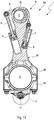
- einen Längsschnitt durch ein erstes Ausführungsbeispiel eines erfindungsgemäßen Pleuels;a longitudinal section through a first embodiment of a connecting rod according to the invention;
- Fig. 2Fig. 2
-
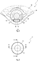
einen vergrößerten Ausschnitt Z des Längsschnitts gemäß
Fig. 1 mit Fokus auf das Umschaltventil in einem Querschnitt;an enlarged section Z of the longitudinal section according toFig. 1 with focus on the switching valve in a cross section; - Fig. 3Fig. 3
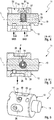
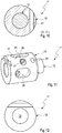
- eine Draufsicht auf das Umschaltventil gemäß einem Ausführungsbeispiel der Erfindung mit eingezeichneten Schnittebenen A-A und B-B;a plan view of the switching valve according to an embodiment of the invention with marked sectional planes A-A and B-B;
- Fig. 4Fig. 4
-
einen Längsschnitt durch das Umschaltventil in der Schnittebene A-A gemäß
Fig. 3 ;a longitudinal section through the switching valve in the sectional plane AA according toFig. 3 ; - Fig. 5Fig. 5
-
einen weiteren Längsschnitt durch das Umschaltventil in der Schnittebene B-B gemäß
Fig. 3 ;a further longitudinal section through the switching valve in the sectional plane BB according toFig. 3 ; - Fig. 6Fig. 6
-
eine isometrische Darstellung des Umschaltventils gemäß
Fig. 3 ;an isometric view of the switching valve according toFig. 3 ; - Fig. 7Fig. 7
-
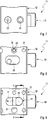
eine Seitenansicht des Umschaltventils gemäß
Fig. 3 ;a side view of the switching valve according toFig. 3 ; - Fig. 8Fig. 8
-
eine weitere Seitenansicht des Umschaltventils gemäß
Fig. 3 ;another side view of the switching valve according toFig. 3 ; - Fig. 9Fig. 9
-
eine weitere Seitenansicht des Umschaltventils gemäß
Fig. 3 mit eingezeichneter Schnittebene C-C;another side view of the switching valve according toFig. 3 with marked section plane CC; - Fig. 10Fig. 10
-
einen Querschnitt durch das Umschaltventil in der Schnittebene C-C gemäß
Fig. 9 ;a cross section through the switching valve in the sectional plane CC according toFig. 9 ; - Fig. 11Fig. 11
-
eine weitere isometrische Darstellung des Umschaltventils gemäß
Fig. 3 ;a further isometric view of the switching valve according toFig. 3 ; - Fig. 12Fig. 12
-
eine Draufsicht auf das Umschaltventil gemäß
Fig. 3 ;a plan view of the switching valve according toFig. 3 ; - Fig. 13Fig. 13
- einen Längsschnitt durch ein weiteres Ausführungsbeispiel eines erfindungsgemäßen Pleuels;a longitudinal section through a further embodiment of a connecting rod according to the invention;
- Fig. 14Fig. 14
-
einen vergrößerten Ausschnitt Z des Längsschnitts gemäß
Fig. 13 mit Fokus auf das Umschaltventil in einem Querschnitt;an enlarged section Z of the longitudinal section according toFig. 13 with focus on the switching valve in a cross section; - Fig. 15Fig. 15
-
eine isometrische Darstellung des Umschaltventils gemäß
Fig. 13 ;an isometric view of the switching valve according toFig. 13 ; - Fig. 16Fig. 16
-
eine Draufsicht auf das Umschaltventil gemäß
Fig. 13 mit eingezeichneter Schnittebene A-A; unda plan view of the switching valve according toFig. 13 with marked section plane AA; and - Fig. 17Fig. 17
-
einen Längsschnitt durch das Umschaltventil in der Schnittebene A-A gemäß
Fig. 16 .a longitudinal section through the switching valve in the sectional plane AA according toFig. 16 ,
In den Figuren sind gleiche oder gleichartige Komponenten mit gleichen Bezugszeichen beziffert. Die Figuren zeigen lediglich Beispiele und sind nicht beschränkend zu verstehen.In the figures, the same or similar components are numbered with the same reference numerals. The figures are merely examples and are not intended to be limiting.
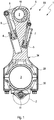
Die
Der in
Eine Verdrehung der verstellbaren Exzenter-Verstelleinrichtung 6 wird durch Einwirken von Massen- und Lastkräften der Brennkraftmaschine eingeleitet, die bei einem Arbeitstakt der Brennkraftmaschine auf die Exzenter-Verstelleinrichtung 6 wirken. Während eines Arbeitstaktes verändern sich die Wirkungsrichtungen der auf die Exzenter-Verstelleinrichtung 6 wirkenden Kräfte kontinuierlich. Die Drehbewegung oder Verstellbewegung wird durch mit Hydraulikflüssigkeit, insbesondere mit Motoröl, beaufschlagte, im Pleuel 1 integrierte Kolben 4, 5 unterstützt. Die Kolben 4, 5 verhindern dabei ein Rückstellen der Exzenter-Verstelleinrichtung 6 aufgrund variierender Kraftwirkungsrichtungen der auf die Exzenter- Verstelleinrichtung 6 wirkenden Kräfte.A rotation of the adjustable
Die Kolben 4, 5 sind mittels Exzenterstangen 7, 8 beidseitig mit einem Hebel 9 der Exzenter-Verstelleinrichtung 6 wirkverbunden. Die Kolben 4, 5 sind in Hydraulikkammern verschiebbar angeordnet und über nicht gezeigte Hydraulikflüssigkeitsleitungen mit Hydraulikflüssigkeit über nicht sichtbare Rückschlagventile beaufschlagt. Die Rückschlagventile verhindern dabei ein Rückfließen der Hydraulikflüssigkeit aus den Hydraulikkammern zurück in die Hydraulikflüssigkeitsleitungen und ermöglichen ein Nachsaugen von Hydraulikflüssigkeit in die Hydraulikkammern.The
Die Rückschlagventile können vorteilhafterweise in das Umschaltventil 11 beispielsweise als Kugel- oder Tellerrückschlagventile oder als Bandrückschlagventile integriert sein. Bei der Ausführung als Bandrückschlagventile kann beispielsweise eine Lagesicherung wie ein Bolzen o.ä. vorgesehen sein. Die mit den Hydraulikkammern verbundenen Hydraulikflüssigkeitsleitungen wirken alle oder wenigstens teilweise mit dem erfindungsgemäßen Umschaltventil 11 zusammen. In einer ersten Schaltstellung S1 des Umschaltventils 11, welche einer Stellung hoher Verdichtung des Pleuels 1 entspricht (dargestellt in
Das nachfolgend näher beschriebene Umschaltventil 11 kann aber auch für jeden anderen Pleuel für eine Brennkraftmaschine mit variabler Verdichtung vorgesehen sein, welche eine Exzenter-Verstelleinrichtung zur Verstellung einer effektiven Pleuelstangenlänge und wenigstens einer Hydraulikkammer aufweist. Beispielsweise kann die Exzenter-Verstelleinrichtung des Pleuels mit einem sogenannten Schwenkmotor-System ausgebildet sein.However, the reversing
Das Umschaltventil 11 ist in
Wie in
Zur Aufnahme des nicht gezeigten Sicherungsstiftes weist der Pleuel 1 Bohrungen 32 auf, welche im zweiten Ausführungsbeispiel in
Im Querschnitt in
Im Längsschnitt des Umschaltventils 11 in
Das Umschaltventil 11 weist ein in einem Ventilgehäuse 12 angeordnetes Abgriffselement 13 auf, welches in einer axialen Richtung L (siehe
Das in dem Ventilgehäuse 12 angeordnete Abgriffselement 13 ist wahlweise in der ersten Schaltstellung S1 oder der zweiten Schaltstellung S2 arretierbar. Hierfür sind das Rastelement 14 und das in dem Rastelement 14 angeordnete Federelement 15 wenigstens teilweise in einer quer ausgebildeten Ausnehmung 16 des Abgriffselements 13 angeordnet. Das Ventilgehäuse 12 weist dazu in der axialen Richtung L eine axial begrenzte erste Nut 17 auf, in welcher das Rastelement 14 zur Begrenzung des Schaltweges und zur Verdrehsicherung des Abgriffselements 13 axial verschiebbar angeordnet ist. Die zumindest teilweise Anordnung des Rastelementes 14 in der Ausnehmung 16 ist von Vorteil, da die Führungslänge des beweglichen Rastelementes 14 im Vergleich zu den bekannten Umschaltventilen entscheidend vergrößert werden kann. Die Verkantungsneigung und Selbsthemmungsneigung kann verringert und ein sicheres Erreichen der Endlagen aus eigener Kraft verbessert werden. Zudem ist die Federauslegung des Federelements 15 wegen größerer Einbaulänge im Vergleich zum Stand der Technik nicht kritisch.The arranged in the
Das Rastelement 14 dient zusätzlich als Anschlagelement, welches einen Verschiebeweg des Abgriffselements 13 im Ventilgehäuse 12 begrenzt. Dadurch kann das Anschlagelement als zusätzliches Bauteil entfallen. Das Rastelement 14 ist mit dem Abgriffselement 13 zusammen axial verschiebbar vorgesehen. Das Rastelement 14 wirkt mit einem Rastpin 18 zusammen, welcher im Ventilgehäuse 12 im Bereich der ersten Nut 17 angeordnet ist.The locking
Um das Umschaltventil 11 in den beiden Schaltstellungen S1 und S2 zu arretieren, weist das Rastelement 14 eine Rastkontur 19 auf, welche im Zusammenspiel mit dem Rastpin 18 zwei Rastpositionen für das Rastelement 14 ermöglicht. Wie
Wie
Die Seitenansicht in
Zur Aufnahme eines Sicherungsstiftes weist der Pleuel 1 Bohrungen 32 auf, wie bei dem Ausführungsbeispiel in
Eine Bohrung des Pleuels 1 könnte alternativ als Sacklochbohrung ausgebildet sein, wodurch vorteilhaft Restschmutz vermieden werden kann. Ferner kann der Einpressvorgang dadurch vereinfacht werden, dass der Einpressvorgang nicht mehr bezüglich des Weges überwacht werden muss.A bore of the connecting
In
Den
Wie insbesondere dem vergrößerten Ausschnitt in
Alternativ können die Bohrungen 32 auch als Sacklochbohrungen vorgesehen sein. Die Bohrungen 32 können günstigerweise eine Spielpassung aufweisen, in welcher der ein oder mehrere Sicherungsstifte durch Umformen der Enden, beispielsweise Umbördeln, gegen Herausfallen gesichert ist.Alternatively, the
Für die Montage ergibt sich die Situation, dass das Umschaltventil 11 nicht mehr vormontiert werden kann, da der Rastpin 18 erst nach Einpressen des Ventilgehäuses 12 eingepresst wird. Die Montage des Rastpins 18 erfolgt also nach dem Einpressen des Ventilgehäuses 12 in die Bohrung 23 im Pleueldeckel 30. Im Pleueldeckel 30 ist daher zweckmäßigerweise mindestens eine Bohrung 31 eingebracht, durch welche das Rastelement 14 in das Ventilgehäuse 12 eingebracht werden kann. Alternativ ist eine Langlochnut denkbar.For assembly results in the situation that the switching
Als weitere alternative Ausführung kann vorgesehen sein, einen temporären Rastpin in das Ventilgehäuse 12 zu montieren, welcher nicht aus dem Ventilgehäuse 12 heraussteht und mittels des endgültigen Rastpins 18 bei dessen Montage herausgestoßen wird. Der temporäre Rastpin kann eine Presspassung, eine Übergangspassung oder eine Spielpassung haben.As a further alternative embodiment can be provided to mount a temporary locking pin in the
In einer alternativen Ausführungsform kann das Ventilgehäuse 12 jedoch auch mittels einer stirnseitigen Schweißnaht als Sicherungselement an dem Pleueldeckel 30 fixiert sein.In an alternative embodiment, however, the
In der isometrischen Darstellung in
Claims (14)
wobei das Rastelement (14) mit einem Rastpin (18) zusammenwirkt, welcher im Ventilgehäuse (12) im Bereich der ersten Nut (17) angeordnet ist.Switching valve (11) for controlling a hydraulic fluid flow, with a in a valve housing (12) arranged Abgriffselement (13) which selectively in a first switching position (S1) or a second switching position (S2) displaceable and by means of a Federelementbeaufschlagten locking element (14) optionally in the first or the second switching position (S1, S2) can be locked, wherein in the first switching position (S1) a first hydraulic connection (22) with a discharge port (26) and in the second switching position (S2) a second hydraulic port (24) with the Relief connection (26) is connected, wherein a switching path of the Abgriffselements (13) is provided limited, wherein the latching element (14) at least partially in a recess (16) of the Abgriffselements (13) is arranged and the valve housing (12) in an axial direction (L) has an axially limited first groove (17) in which the latching element (14) with the tapping element (13) axially slidably angeord is net,
wherein the latching element (14) cooperates with a latching pin (18) which is arranged in the valve housing (12) in the region of the first groove (17).
Priority Applications (1)
| Application Number | Priority Date | Filing Date | Title |
|---|---|---|---|
| EP19150637.7A EP3502436B1 (en) | 2017-09-04 | 2018-08-21 | Connecting rod for a combustion engine with variable compression with a switching valve |
Applications Claiming Priority (2)
| Application Number | Priority Date | Filing Date | Title |
|---|---|---|---|
| DE102017120255 | 2017-09-04 | ||
| DE102018107108.6A DE102018107108A1 (en) | 2017-09-04 | 2018-03-26 | Switching valve for controlling a hydraulic fluid flow and connecting rod for a variable compression internal combustion engine with a switching valve |
Related Child Applications (2)
| Application Number | Title | Priority Date | Filing Date |
|---|---|---|---|
| EP19150637.7A Division EP3502436B1 (en) | 2017-09-04 | 2018-08-21 | Connecting rod for a combustion engine with variable compression with a switching valve |
| EP19150637.7A Division-Into EP3502436B1 (en) | 2017-09-04 | 2018-08-21 | Connecting rod for a combustion engine with variable compression with a switching valve |
Publications (2)
| Publication Number | Publication Date |
|---|---|
| EP3450720A2 true EP3450720A2 (en) | 2019-03-06 |
| EP3450720A3 EP3450720A3 (en) | 2019-04-24 |
Family
ID=63350398
Family Applications (2)
| Application Number | Title | Priority Date | Filing Date |
|---|---|---|---|
| EP18189918.8A Withdrawn EP3450720A3 (en) | 2017-09-04 | 2018-08-21 | Switching valve for controlling a hydraulic fluid stream and connecting rod for a combustion engine with variable compression with a switching valve |
| EP19150637.7A Active EP3502436B1 (en) | 2017-09-04 | 2018-08-21 | Connecting rod for a combustion engine with variable compression with a switching valve |
Family Applications After (1)
| Application Number | Title | Priority Date | Filing Date |
|---|---|---|---|
| EP19150637.7A Active EP3502436B1 (en) | 2017-09-04 | 2018-08-21 | Connecting rod for a combustion engine with variable compression with a switching valve |
Country Status (1)
| Country | Link |
|---|---|
| EP (2) | EP3450720A3 (en) |
Cited By (1)
| Publication number | Priority date | Publication date | Assignee | Title |
|---|---|---|---|---|
| CN112324565A (en) * | 2019-08-05 | 2021-02-05 | 伊希欧1控股有限公司 | Connecting rod for an internal combustion engine with variable compression ratio |
Citations (1)
| Publication number | Priority date | Publication date | Assignee | Title |
|---|---|---|---|---|
| DE102012112461A1 (en) | 2012-12-18 | 2014-06-18 | Dr. Ing. H.C. F. Porsche Aktiengesellschaft | Reversing valve for controlling engine oil of internal combustion engine i.e. petrol engine, in motor car, has groove connecting first and second hydraulic fluid lines to vent channel in first and second switch positions, respectively |
Family Cites Families (9)
| Publication number | Priority date | Publication date | Assignee | Title |
|---|---|---|---|---|
| DE102013206513A1 (en) * | 2013-04-12 | 2014-10-16 | Dr. Ing. H.C. F. Porsche Aktiengesellschaft | Changeover valve and internal combustion engine with such a changeover valve |
| DE102013105389B4 (en) * | 2013-05-27 | 2021-12-23 | Dr. Ing. H.C. F. Porsche Aktiengesellschaft | Changeover valve and internal combustion engine with such a changeover valve |
| DE102015100662A1 (en) * | 2014-12-19 | 2016-06-23 | Hilite Germany Gmbh | Hydraulic valve for switching a control piston of a connecting rod |
| DE102015202065A1 (en) * | 2015-02-05 | 2016-08-11 | Schaeffler Technologies AG & Co. KG | Reversing valve with reset function for an internal combustion engine |
| DE102015202051A1 (en) * | 2015-02-05 | 2016-08-11 | Schaeffler Technologies AG & Co. KG | switching valve |
| DE102015202056A1 (en) * | 2015-02-05 | 2016-08-11 | Schaeffler Technologies AG & Co. KG | Valve housing for a bivalent switching valve |
| DE102015203378A1 (en) * | 2015-02-25 | 2016-08-25 | Fev Gmbh | Internal combustion engine with adjustable variable compression ratio and a switching module |
| DE102015203417B4 (en) * | 2015-02-26 | 2016-09-15 | Schaeffler Technologies AG & Co. KG | switching valve |
| DE102015111175A1 (en) * | 2015-03-26 | 2016-09-29 | Hilite Germany Gmbh | Hydraulic valve and connecting rod with a hydraulic valve |
-
2018
- 2018-08-21 EP EP18189918.8A patent/EP3450720A3/en not_active Withdrawn
- 2018-08-21 EP EP19150637.7A patent/EP3502436B1/en active Active
Patent Citations (1)
| Publication number | Priority date | Publication date | Assignee | Title |
|---|---|---|---|---|
| DE102012112461A1 (en) | 2012-12-18 | 2014-06-18 | Dr. Ing. H.C. F. Porsche Aktiengesellschaft | Reversing valve for controlling engine oil of internal combustion engine i.e. petrol engine, in motor car, has groove connecting first and second hydraulic fluid lines to vent channel in first and second switch positions, respectively |
Cited By (2)
| Publication number | Priority date | Publication date | Assignee | Title |
|---|---|---|---|---|
| CN112324565A (en) * | 2019-08-05 | 2021-02-05 | 伊希欧1控股有限公司 | Connecting rod for an internal combustion engine with variable compression ratio |
| CN112324565B (en) * | 2019-08-05 | 2022-09-13 | 伊希欧1控股有限公司 | Connecting rod for an internal combustion engine with variable compression ratio |
Also Published As
| Publication number | Publication date |
|---|---|
| EP3502436B1 (en) | 2020-11-04 |
| EP3450720A3 (en) | 2019-04-24 |
| EP3502436A1 (en) | 2019-06-26 |
Similar Documents
| Publication | Publication Date | Title |
|---|---|---|
| AT518848B1 (en) | Connecting rod with adjustable connecting rod length with mechanical actuation | |
| DE102015109474A1 (en) | Changeover valve and connecting rod with a changeover valve | |
| DE102017121443A1 (en) | Check valve for a connecting rod of an internal combustion engine with variable compression and connecting rod with such a check valve | |
| WO2018007534A1 (en) | Connecting rod having an adjustable connecting rod length with a mechanical actuating means | |
| EP3464851B1 (en) | Switchover valve for controlling a hydraulic fluid flow, and connecting rod for a variable-compression internal combustion engine having a switchover valve | |
| DE102018107108A1 (en) | Switching valve for controlling a hydraulic fluid flow and connecting rod for a variable compression internal combustion engine with a switching valve | |
| EP3502436B1 (en) | Connecting rod for a combustion engine with variable compression with a switching valve | |
| EP3404232B1 (en) | Connecting rod for a combustion engine with variable compression | |
| EP3085921B1 (en) | Connecting rod with switching valve | |
| DE102018117451A1 (en) | Check valve for a connecting rod of an internal combustion engine with variable compression and connecting rod with such a check valve | |
| EP3361069B1 (en) | Connecting rod of a combustion engine with variable compression with a check valve | |
| DE102006044294B3 (en) | Radial piston pump for internal combustion engine, has pump units with cross heads having cross head bolts that are supported in small lugs of piston rod, where lugs are designed as slotted holes with longitudinal axes | |
| DE102017107719A1 (en) | Hydraulic valve for adjusting a hydraulic fluid flow of a connecting rod for a variable compression internal combustion engine | |
| DE102017107673A1 (en) | Connecting rod for a variable compression of an internal combustion engine | |
| AT15890U1 (en) | Multi-part connecting rod with adjustable connecting rod length | |
| DE102016104958A1 (en) | Check valve for a connecting rod for a variable compression internal combustion engine and connecting rod with a check valve | |
| EP3073095B1 (en) | Hydraulic valve and a connecting rod with a hydraulic valve | |
| AT524567B1 (en) | Length-adjustable connecting rod with compact drain valve | |
| EP3364010A1 (en) | Connecting rod for a combustion engine with variable compression | |
| DE102017107706A1 (en) | Length-adjustable connecting rod with a cylinder-piston unit with anti-rotation | |
| DE102022106130B4 (en) | Automotive component | |
| EP3546722B1 (en) | Connecting rod for a combustion engine with variable compression | |
| EP3267012A1 (en) | Check valve for a connecting rod for a combustion engine with variable compression | |
| AT522162B1 (en) | Assembly method of a connecting rod part fixed to the housing of a length-adjustable connecting rod | |
| DE10153336A1 (en) | Pressure medium cylinder with a device for adjusting the piston stroke |
Legal Events
| Date | Code | Title | Description |
|---|---|---|---|
| PUAI | Public reference made under article 153(3) epc to a published international application that has entered the european phase |
Free format text: ORIGINAL CODE: 0009012 |
|
| AK | Designated contracting states |
Kind code of ref document: A2 Designated state(s): AL AT BE BG CH CY CZ DE DK EE ES FI FR GB GR HR HU IE IS IT LI LT LU LV MC MK MT NL NO PL PT RO RS SE SI SK SM TR |
|
| AX | Request for extension of the european patent |
Extension state: BA ME |
|
| PUAL | Search report despatched |
Free format text: ORIGINAL CODE: 0009013 |
|
| AK | Designated contracting states |
Kind code of ref document: A3 Designated state(s): AL AT BE BG CH CY CZ DE DK EE ES FI FR GB GR HR HU IE IS IT LI LT LU LV MC MK MT NL NO PL PT RO RS SE SI SK SM TR |
|
| AX | Request for extension of the european patent |
Extension state: BA ME |
|
| RIC1 | Information provided on ipc code assigned before grant |
Ipc: F02B 75/04 20060101AFI20190318BHEP Ipc: F16K 11/07 20060101ALI20190318BHEP |
|
| 17P | Request for examination filed |
Effective date: 20190520 |
|
| RBV | Designated contracting states (corrected) |
Designated state(s): AL AT BE BG CH CY CZ DE DK EE ES FI FR GB GR HR HU IE IS IT LI LT LU LV MC MK MT NL NO PL PT RO RS SE SI SK SM TR |
|
| STAA | Information on the status of an ep patent application or granted ep patent |
Free format text: STATUS: THE APPLICATION IS DEEMED TO BE WITHDRAWN |
|
| 18D | Application deemed to be withdrawn |
Effective date: 20191025 |