EP3450325B1 - Satellit mit einem thermoschalter und zugehörige verfahren - Google Patents
Satellit mit einem thermoschalter und zugehörige verfahren Download PDFInfo
- Publication number
- EP3450325B1 EP3450325B1 EP18190896.3A EP18190896A EP3450325B1 EP 3450325 B1 EP3450325 B1 EP 3450325B1 EP 18190896 A EP18190896 A EP 18190896A EP 3450325 B1 EP3450325 B1 EP 3450325B1
- Authority
- EP
- European Patent Office
- Prior art keywords
- thermal
- temperature sensitive
- sensitive component
- satellite
- radiator
- Prior art date
- Legal status (The legal status is an assumption and is not a legal conclusion. Google has not performed a legal analysis and makes no representation as to the accuracy of the status listed.)
- Active
Links
Images


Classifications
-
- B—PERFORMING OPERATIONS; TRANSPORTING
- B64—AIRCRAFT; AVIATION; COSMONAUTICS
- B64G—COSMONAUTICS; VEHICLES OR EQUIPMENT THEREFOR
- B64G1/00—Cosmonautic vehicles
- B64G1/22—Parts of, or equipment specially adapted for fitting in or to, cosmonautic vehicles
- B64G1/46—Arrangements or adaptations of devices for control of environment or living conditions
- B64G1/50—Arrangements or adaptations of devices for control of environment or living conditions for temperature control
- B64G1/503—Radiator panels
-
- B—PERFORMING OPERATIONS; TRANSPORTING
- B64—AIRCRAFT; AVIATION; COSMONAUTICS
- B64G—COSMONAUTICS; VEHICLES OR EQUIPMENT THEREFOR
- B64G1/00—Cosmonautic vehicles
- B64G1/10—Artificial satellites; Systems of such satellites; Interplanetary vehicles
-
- B—PERFORMING OPERATIONS; TRANSPORTING
- B64—AIRCRAFT; AVIATION; COSMONAUTICS
- B64G—COSMONAUTICS; VEHICLES OR EQUIPMENT THEREFOR
- B64G1/00—Cosmonautic vehicles
- B64G1/22—Parts of, or equipment specially adapted for fitting in or to, cosmonautic vehicles
- B64G1/66—Arrangements or adaptations of apparatus or instruments, not otherwise provided for
-
- H—ELECTRICITY
- H01—ELECTRIC ELEMENTS
- H01H—ELECTRIC SWITCHES; RELAYS; SELECTORS; EMERGENCY PROTECTIVE DEVICES
- H01H37/00—Thermally-actuated switches
- H01H37/02—Details
Definitions
- the present invention relates to the field of satellites, and more particularly, to a thermal switch for a temperature sensitive component within a satellite and related methods.
- small satellites for commercial and government uses are significantly increasing. Small satellites are characterized as satellites of low mass and size, usually under 500 kg. A low earth orbit (LEO) is used by a vast majority of small satellites. The altitude range of small satellites in a low earth orbit is within a range of about 200 and 1200 km above the Earth's surface, with an orbital period within a range of about 84 to 127 minutes.
- LEO low earth orbit
- Small satellites may be used to provide worldwide voice and data communications for hand-held satellite phones and other transceiver units, for example. Another application of small satellites is to monitor the surface of the earth.
- thermal radiators When temperature sensitive components are powered on, thermal radiators may be used to dump or radiate heat to cold space to keep the temperature sensitive components from getting too hot. When temperature sensitive components are powered off, heaters may be used to keep the temperature sensitive components from getting too cold.
- a temperature sensitive component coupled to a thermal radiator when a temperature sensitive component coupled to a thermal radiator is powered off, the thermal radiator may continue to radiate heat to cold space. This means that the heater consumes additional DC power to compensate for the heat being radiated by the thermal radiator. Since the solar panels for small satellites are limited in size, their battery charging capabilities are limited as well. Consequently, there is a need for small satellites to conserve DC power consumption.
- Document US3390717 a device with an outer wall may comprise the exterior skin of a space vehicle. Within the space vehicle, a heat generating device such as an electrical power supply. When device is operating, heat should be dissipated by radiation from skin to keep the temperature within the space vehicle below a predetermined amount.
- the sensing and actuation device measures the temperature of the heat generating equipment so as to be responsive thereto and move plate toward or away from balls depending on the temperature.
- a solenoid is provided within the sensing and actuation device so as to force leg toward or away from plate and hence plate is forced toward or away from balls and plate.
- Document US3463224 discloses a heat transfer switch which utilizes an expandable liquid in a container which when heated will expand to force one heat transfer element into heat transfer contact with another element.
- the device is temperature sensitive in that below a very narrow range of temperature, little heat transfer is accomplished while in and above this narrow range of temperature a great deal of heat is transferred.
- Override springs are provided to prevent damage to the switch and to insure a gap between the heat transfer elements.
- Document US2011168378 discloses a power distribution system comprised of one or more variably conductive thermal switches. The thermal switches are sandwiched between two thermal conductors. Within each thermal switch is an array of micro-switches with a number of finger-like structures that are electrically actuated to form one or more thermal connection between two thermally conductive layers. The net thermal conductance of the switch is scalable based on the number of activated micro-switches.
- Document EP1006769 discloses a thermal radiative system for an earth orbiting satellite including a plurality of faces intermittently exposed to maximum solar illumination comprises a thermal radiator is mounted on a face for discharging heat from a thermal load to deep space. A heat conductor extends between the thermal load and the thermal radiator. Thermal switches are operable for connecting the thermal load to the thermal radiator for cooling when the temperature of the thermal load is above a predetermined level and for disconnecting the thermal load from the thermal radiator when the temperature of the thermal load falls below the predetermined level. A shield including phase change management material is thermally connected to the thermal load for drawing heat away therefrom.
- the thermal switch advantageously helps the satellite conserve DC power when the thermal radiator is thermally decoupled from the temperature sensitive component.
- the thermal decoupling prevents the thermal switch from radiating valuable heat from the temperature sensitive component when the temperature sensitive component is powered off. As a result, less DC power is needed to heat the temperature sensitive component when the thermal radiator is thermally decoupled from the temperature sensitive component.
- the thermal switch may comprise an electromagnetically operated actuator.
- the electromagnetically operated actuator may comprise a solenoid coil, and at least one flexure mount coupled between the temperature sensitive component and the thermal radiator.
- the electromagnetically operated actuator may comprise at least one solenoid fastener coupled between the temperature sensitive component and the thermal radiator.
- a compressible thermal interface layer may be between the temperature sensitive component and the thermal radiator when the thermal switch is in the coupled state.
- the satellite may further comprise a temperature sensor associated with the temperature sensitive component, and a controller to operate the thermal switch based upon the temperature sensor to maintain the temperature sensitive component within a temperature range.
- the satellite may further comprise a heater associated with the temperature sensitive component and controllable by the controller.
- the temperature sensitive component may comprise an electronic circuit device or a battery, for example.
- Another aspect is directed to a method, according to the appended claims, of maintaining the temperature sensitive component of the satellite within a temperature range.
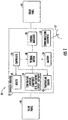
- a satellite 20 includes a satellite housing 22 , a temperature sensitive component 24 , a thermal radiator 28 , and a thermal switch 30.
- the temperature sensitive component 24 , the thermal radiator 28 , and the thermal switch 30 are carried by the satellite housing 22.
- the satellite housing 22 may be the main body of the satellite 20 , as illustrated. Alternatively, the satellite housing 22 may be carried on a support arm away from the main body of the satellite 20.
- the satellite 20 further includes communications equipment 35 and an antenna 37 coupled thereto.
- the thermal switch 30 is movable between a coupled state and a decoupled stated.
- the temperature sensitive component 24 In the coupled state, the temperature sensitive component 24 is thermally coupled to the thermal radiator 28.
- the temperature sensitive component 24 In the decoupled state, the temperature sensitive component 24 is thermally decoupled from the thermal radiator 28.
- a vacuum gap 33 is defined between the temperature sensitive component 24 and the thermal radiator 28.
- the thermal switch 30 advantageously helps the satellite 20 conserve DC power when the thermal radiator 28 is thermally decoupled from the temperature sensitive component 24 while the temperature sensitive component 24 is being heated by a heater 32. This prevents the thermal switch 30 from radiating valuable heat from the temperature sensitive component 24 when the temperature sensitive component 24 is powered off. As a result, less DC power is needed to heat the temperature sensitive component 24 when the thermal radiator 28 is thermally decoupled from the temperature sensitive component 24.
- the satellite 20 operates on DC power provided by a battery 34. Solar panels 40 are used to charge the battery 34.
- the satellite 20 may be a low earth orbit (LEO) satellite, for example. LEO satellites are often referred to as small satellites since they are characterized as having low mass and size.
- the solar panels 40 for a small satellite are limited in size, which means their battery charging capabilities are limited as well. Decoupling the thermal radiator 28 from the temperature sensitive component 24 allows the satellite 20 to conserve DC power consumption when operating a heater 32 to heat the temperature sensitive component 24.
- the heater 32 may be external the temperature sensitive component 24 , as illustrated. Alternatively, the heater 32 may be internal the temperature sensitive component 24 , as readily understood by those skilled in the art.
- the satellite 20 further includes a temperature sensor 42 associated with the temperature sensitive component 24.
- a controller 50 is configured to operate the heater 32 and the thermal switch 30 based upon the temperature sensor 42.
- the small satellite 20 may experience a temperate range of - 55 ⁇ S / cm (EC) to +200 ⁇ S / cm (EC).
- the temperature sensitive component 24 is an electronic circuit device, it is typically limited to a temperature range of -40 ⁇ S / cm (EC) to +85 ⁇ S /cm(EC), for example, to avoid being damaged.
- the electronic circuit device may be a microprocessor or a high power amplifier (HPA), for example.
- HPA high power amplifier
- the temperature sensitive component 24 is a battery, for example, it has an even more limited temperature range. Batteries are typically limited to a temperature range of +10 ⁇ S / cm ( EC ) to +50 ⁇ S / cm (EC), for example.
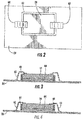
- the thermal switch 30 may be configured as an electromagnetically operated actuator. Referring now to FIGS. 2-4 , one embodiment of the electromagnetically operated actuator will be discussed.
- the electromagnetically operated actuator comprises a solenoid coil 60, and at least one flexure mount 62 coupled between the temperature sensitive component 24 and the thermal radiator 28. In the illustrated embodiment, two flexure mounts 62 are used.
- the flexure mounts 62 are switched on, as illustrated in FIG. 3 .
- the temperature sensitive component 24 is thermally coupled to the thermal radiator 28.
- a compressible thermal interface layer 64 is carried by the temperature sensitive component 24.
- the compressible thermal interface layer 64 may be carried by the thermal radiator 28.
- the compressible thermal interface layer 64 makes contact with the thermal radiator 28 and the temperature sensitive component 24 when the thermal switch 30 is in the coupled state.
- the compressible thermal interface layer 64 may be indium foil, for example.
- the compressible thermal interface layer 64 is a thermally conductive pad that is compressible.
- the thermally conductive pad is compressible since it includes nanotubes. In an example not part of the present invention the conductive pad includes heat springs.
- a thickness of the compressible thermal interface layer 64 may be within a range of 0.0762 to 0.127 mm (3 to 5 mils) thick, for example.
- the flexure mounts 62 are switched off as illustrated in FIG. 4 .
- a vacuum gap is between the temperature sensitive component 24 and the thermal radiator 28.
- An example electromagnetic force for a temperature sensitive component 24 having a 0.11 cm 2 contact surface area is between 206.8427 to 241.3165 kPa (30 to 35 psi).
- application of an electrical current causes the temperature sensitive component 24 to be thermally coupled to the thermal radiator 28. This configured is preferred when the thermal switch 30 is in a normally powered off state. Alternatively, if the thermal switch 30 is in a normally powered on state, then operation of the thermal switch 30 may be reversed. In this case, application of an electrical current causes the temperature sensitive component 24 to be thermally decoupled from the thermal radiator 28.
- the electromagnetically operated actuator comprises at least one solenoid fastener 70 coupled between the temperature sensitive component 24 and the thermal radiator 28.
- the electromagnetically operated actuator comprises at least one solenoid fastener 70 coupled between the temperature sensitive component 24 and the thermal radiator 28.
- four solenoid fasteners 70 are used, one adjacent each corner of the temperature sensitive component 24.
- Each solenoid fastener 70 includes activation wires 72 contacting an electromagnetic solenoid bolt 74 , and a fastener 76 on the back side of the thermal radiator 28.
- a conductive plate 78 may be included on a backside of the thermal radiator 28 , as illustrated.
- the electromagnetic solenoid bolts 74 When an electrical current is applied to the activation wires 72 , the electromagnetic solenoid bolts 74 are switched on, as illustrated in FIG. 3 . When the electromagnetic solenoid bolts 74 are switched on, the temperature sensitive component 24 is thermally coupled to the thermal radiator 28. When the electrical current is not being applied to the activation wires 72 , the electromagnetic solenoid bolts 74 are switched off so that a vacuum gap is between the temperature sensitive component 24 and the thermal radiator 28.
- the method includes monitoring a temperature sensor 42 associated with the temperature sensitive component 24 at Block 94. If the temperature sensitive component 24 is too hot based upon the temperature sensor 42 , then a thermal switch 30 is selectively operated at Block 96 to a coupled state with the temperature sensitive component 24 and the thermal radiator 28 being thermally coupled. If the temperature sensitive component 24 is too cold based upon the temperature sensor 42 , then a heater 32 and the thermal switch 30 are selectively operated at Block 98 to a decoupled state with the temperature sensitive component 24 and the thermal radiator 28 being thermally decoupled. The method ends at Block 100.
Landscapes
- Engineering & Computer Science (AREA)
- Remote Sensing (AREA)
- Aviation & Aerospace Engineering (AREA)
- Environmental & Geological Engineering (AREA)
- Environmental Sciences (AREA)
- General Health & Medical Sciences (AREA)
- Toxicology (AREA)
- Health & Medical Sciences (AREA)
- Biodiversity & Conservation Biology (AREA)
- Life Sciences & Earth Sciences (AREA)
- Physics & Mathematics (AREA)
- Astronomy & Astrophysics (AREA)
- General Physics & Mathematics (AREA)
- Thermally Actuated Switches (AREA)
- Cooling Or The Like Of Electrical Apparatus (AREA)
Claims (9)
- Satellit (20) umfassend:ein Satellitengehäuse (22);eine temperaturempfindliche Komponente (24), die von dem Satellitengehäuse (22) getragen wird;einen thermischen Strahler (28), der von dem Satellitengehäuse (22) getragen wird;einen Thermoschalter (30), der zwischen einem gekoppelten Zustand, in dem die temperaturempfindliche Komponente (24) und der thermische Strahler (28) thermisch gekoppelt sind, und einem entkoppelten Zustand beweglich ist, in dem die temperaturempfindliche Komponente und der thermische Strahler (28) thermisch entkoppelt sind;ein Heizelement (32), das zum Erwärmen der temperaturempfindlichen Komponente (24) angepasst ist; undeine kompressible thermische Grenzflächenschicht (64) zwischen der temperaturempfindlichen Komponente (24) und dem thermischen Strahler (28), wenn sich der Thermoschalter (30) im gekoppelten Zustand befindet, wobei die kompressible thermische Grenzflächenschicht (64) dadurch gekennzeichnet ist, dass sie ein Wärmeleitpad mit Nanoröhren umfasst.
- Satellit (20) nach Anspruch 1, wobei der Thermoschalter (30) im entkoppelten Zustand einen Vakuumspalt (66) zwischen der temperaturempfindlichen Komponente (24) und dem thermischen Strahler (28) definiert.
- Satellit (20) nach Anspruch 1, wobei der Thermoschalter (30) einen elektromagnetisch betätigten Aktuator umfasst.
- Satellit (20) nach Anspruch 3, wobei der elektromagnetisch betätigte Aktuator eine Solenoidspule (60) und mindestens eine Biegehalterung (62) umfasst, die zwischen der temperaturempfindlichen Komponente (24) und dem thermischen Strahler (28) gekoppelt ist.
- Satellit (20) nach Anspruch 3, wobei der elektromagnetisch betätigte Aktuator Solenoidbefestigungen (70) umfasst, die zwischen der temperaturempfindlichen Komponente (24) und dem thermischen Strahler (28) gekoppelt sind, wobei jede Solenoidbefestigung (70) Aktivierungsdrähte (72) mit einem elektromagnetischen Solenoidbolzen (74) und einem Befestigungselement (76) umfasst, das an der Rückseite des thermischen Strahlers (28) angeordnet ist.
- Satellit (20) nach Anspruch 1, ferner umfassend:einen Temperatursensor (42), der der temperaturempfindlichen Komponente (24) zugeordnet ist; undeine Steuerung (50), die zum Betrieb des Thermoschalters (30) basierend auf dem Temperatursensor (42) eingerichtet ist, um die temperaturempfindliche Komponente (24) innerhalb eines Temperaturbereichs zu halten.
- Verfahren zum Halten einer temperaturempfindlichen Komponente (24) eines Satelliten (20) gemäß einem der Ansprüche 1 bis 6 innerhalb eines Temperaturbereichs, wobei das Verfahren umfasst:selektives Betätigen eines Thermoschalters (30), der zwischen einem gekoppelten Zustand, in dem die temperaturempfindliche Komponente (24) und ein thermischer Strahler (28) thermisch gekoppelt sind, und einem entkoppelten Zustand beweglich ist, in dem die temperaturempfindliche Komponente (24) und der thermische Strahler (28) thermisch entkoppelt sind, um dadurch die temperaturempfindliche Komponente (24) innerhalb des Temperaturbereichs zu halten;selektives Betreiben eines Heizelements (32) zum Erwärmen der temperaturempfindlichen Komponente (24);wobei der Satellit (20) nach Anspruch 1 ferner eine kompressible thermische Grenzflächenschicht (64) zwischen der temperaturempfindlichen Komponente (24) und dem thermischen Strahler (28) umfasst, wenn sich der Thermoschalter (30) im gekoppelten Zustand befindet, wobei die kompressible thermische Grenzflächenschicht (64) ein Wärmeleitpad mit Nanoröhren umfasst.
- Verfahren nach Anspruch 7, wobei der Thermoschalter (30) im entkoppelten Zustand einen Vakuumspalt zwischen der temperaturempfindlichen Komponente (24) und dem thermischen Strahler (28) definiert.
- Verfahren nach Anspruch 7, wobei der Thermoschalter (30) einen elektromagnetisch betätigten Aktuator umfasst.
Applications Claiming Priority (1)
| Application Number | Priority Date | Filing Date | Title |
|---|---|---|---|
| US15/687,808 US10865000B2 (en) | 2017-08-28 | 2017-08-28 | Satellite with a thermal switch and associated methods |
Publications (2)
| Publication Number | Publication Date |
|---|---|
| EP3450325A1 EP3450325A1 (de) | 2019-03-06 |
| EP3450325B1 true EP3450325B1 (de) | 2020-10-28 |
Family
ID=63407085
Family Applications (1)
| Application Number | Title | Priority Date | Filing Date |
|---|---|---|---|
| EP18190896.3A Active EP3450325B1 (de) | 2017-08-28 | 2018-08-27 | Satellit mit einem thermoschalter und zugehörige verfahren |
Country Status (3)
| Country | Link |
|---|---|
| US (2) | US10865000B2 (de) |
| EP (1) | EP3450325B1 (de) |
| KR (1) | KR102317568B1 (de) |
Families Citing this family (7)
| Publication number | Priority date | Publication date | Assignee | Title |
|---|---|---|---|---|
| GB201701833D0 (en) * | 2017-02-03 | 2017-03-22 | Edwards Ltd | Pump cooling systems |
| WO2019055928A1 (en) * | 2017-09-15 | 2019-03-21 | The Government Of The United States Of America, As Represented By The Secretary Of The Navy | METAMATERIALS WITH VARIABLE CONDUCTIVITY AND THERMAL REGULATION SYSTEMS USING SAME |
| FR3093890B1 (fr) * | 2019-03-11 | 2021-07-09 | Continental Automotive Gmbh | Dispositif de diode thermique pour une unité électronique |
| US11834205B1 (en) * | 2019-11-10 | 2023-12-05 | Space Exploration Technologies Corp. | Spacecraft chassis and component configuration |
| CN111086655B (zh) * | 2019-12-16 | 2021-08-24 | 上海卫星工程研究所 | 非测控弧段阴影期热控补偿功率节约方法及系统 |
| FR3114871B1 (fr) | 2020-10-02 | 2023-05-05 | Commissariat A L Energie Atomique Et Aux Energies Alternatives | Interrupteur thermique à actionneur passif pour liaison thermique entre deux éléments, Système embarqué comprenant un tel interrupteur. |
| CN116812174B (zh) * | 2023-05-22 | 2026-03-03 | 东南大学 | 一种基于多级非线性导热的卫星无源热管理结构 |
Family Cites Families (18)
| Publication number | Priority date | Publication date | Assignee | Title |
|---|---|---|---|---|
| US3390717A (en) * | 1966-08-02 | 1968-07-02 | Trw Inc | Heat transfer device |
| US3463224A (en) | 1966-10-24 | 1969-08-26 | Trw Inc | Thermal heat switch |
| US3489203A (en) * | 1967-06-01 | 1970-01-13 | Us Navy | Controlled heat pipe |
| US4374402A (en) | 1980-06-27 | 1983-02-15 | Burroughs Corporation | Piezoelectric transducer mounting structure and associated techniques |
| JPH01195626A (ja) * | 1988-01-29 | 1989-08-07 | Nec Corp | 衛星搭載用サーマルスイッチ |
| US5332030A (en) * | 1992-06-25 | 1994-07-26 | Space Systems/Loral, Inc. | Multi-directional cooler |
| US5535815A (en) | 1995-05-24 | 1996-07-16 | The United States Of America As Represented By The Secretary Of The Navy | Package-interface thermal switch |
| US5771967A (en) | 1996-09-12 | 1998-06-30 | The United States Of America As Represented By The Secretary Of The Navy | Wick-interrupt temperature controlling heat pipe |
| US5875096A (en) * | 1997-01-02 | 1999-02-23 | At&T Corp. | Apparatus for heating and cooling an electronic device |
| US5957408A (en) | 1997-12-05 | 1999-09-28 | Space Systems/Loral, Inc. | Satellite with east and west battery radiators |
| DE19852929C1 (de) | 1998-11-17 | 2000-03-30 | Hanning Elektro Werke | Thermoschalter-Anordnung für elektromagnetische Spulen |
| US6073888A (en) | 1998-12-02 | 2000-06-13 | Loral Space & Communications, Ltd. | Sequenced heat rejection for body stabilized geosynchronous satellites |
| US6511021B1 (en) | 2000-08-01 | 2003-01-28 | Nikolus A. Keramidas | Thermal control system for controlling temperature in spacecraft |
| KR100929601B1 (ko) | 2001-08-20 | 2009-12-03 | 허니웰 인터내셔널 인코포레이티드 | 스냅작동식 열 스위치 |
| US6595004B1 (en) | 2002-04-19 | 2003-07-22 | International Business Machines Corporation | Apparatus and methods for performing switching in magnetic refrigeration systems using thermoelectric switches |
| US7967256B2 (en) * | 2007-05-08 | 2011-06-28 | Lockheed Martin Corporation | Spacecraft battery thermal management system |
| US20110168378A1 (en) | 2010-01-14 | 2011-07-14 | Irvine Sensors Corporation | Thermal power distribution system |
| JP6372785B2 (ja) | 2014-09-30 | 2018-08-15 | パナソニックIpマネジメント株式会社 | パネルユニット |
-
2017
- 2017-08-28 US US15/687,808 patent/US10865000B2/en active Active
-
2018
- 2018-08-27 KR KR1020180100524A patent/KR102317568B1/ko active Active
- 2018-08-27 EP EP18190896.3A patent/EP3450325B1/de active Active
-
2020
- 2020-11-09 US US17/092,972 patent/US11459131B2/en active Active
Non-Patent Citations (1)
| Title |
|---|
| None * |
Also Published As
| Publication number | Publication date |
|---|---|
| EP3450325A1 (de) | 2019-03-06 |
| KR102317568B1 (ko) | 2021-10-26 |
| US10865000B2 (en) | 2020-12-15 |
| KR20190024763A (ko) | 2019-03-08 |
| US20210053701A1 (en) | 2021-02-25 |
| US11459131B2 (en) | 2022-10-04 |
| US20190061979A1 (en) | 2019-02-28 |
Similar Documents
| Publication | Publication Date | Title |
|---|---|---|
| EP3450325B1 (de) | Satellit mit einem thermoschalter und zugehörige verfahren | |
| US7967256B2 (en) | Spacecraft battery thermal management system | |
| EP2814106B1 (de) | Wärmeleitfähigkeitssteuervorrichtungen | |
| GB2545568A (en) | Vehicle antenna assembly with cooling | |
| US9263659B2 (en) | System and method for thermal protection of an electronics module of an energy harvester | |
| US6230790B1 (en) | Thermal control system for spacecraft | |
| JP5018168B2 (ja) | アンテナ装置 | |
| CN109950657A (zh) | 电池系统和用于电池系统的加热设备 | |
| US5467814A (en) | Graphite/epoxy heat sink/mounting for common pressure vessel | |
| US10868345B2 (en) | Battery module and use of such a battery module | |
| CN118387324A (zh) | 一种4d打印智能热控补偿结构 | |
| CN114725647A (zh) | 高功率密度星载sar天线热控装置 | |
| US20030089484A1 (en) | Electrostatic switched radiator for space based thermal control | |
| CN107635819A (zh) | 用于给机动车的电蓄能器感应充电的充电设备和用于运行充电设备的方法 | |
| CN116706492B (zh) | 有源相控阵天线温控装置及卫星 | |
| CN206520763U (zh) | 一种用于临近空间飞行器的无源主动热控装置 | |
| US20200132057A1 (en) | Thermal actuator, and thermal actuator unit | |
| US6511021B1 (en) | Thermal control system for controlling temperature in spacecraft | |
| US20020066723A1 (en) | Heater unit for tray | |
| US6867391B2 (en) | Control system for electrostatic discharge mitigation | |
| JP3726743B2 (ja) | 熱抵抗制御装置 | |
| US20080049398A1 (en) | Apparatus, system, and method for modifying a thermal connection | |
| Sunada et al. | Paraffin actuated heat switch for Mars surface applications | |
| Tsuyuki et al. | Mars exploration rover: Thermal design is a system engineering activity | |
| CN109526190B (zh) | 一种可控制通断的导热机构 |
Legal Events
| Date | Code | Title | Description |
|---|---|---|---|
| PUAI | Public reference made under article 153(3) epc to a published international application that has entered the european phase |
Free format text: ORIGINAL CODE: 0009012 |
|
| STAA | Information on the status of an ep patent application or granted ep patent |
Free format text: STATUS: REQUEST FOR EXAMINATION WAS MADE |
|
| 17P | Request for examination filed |
Effective date: 20180827 |
|
| AK | Designated contracting states |
Kind code of ref document: A1 Designated state(s): AL AT BE BG CH CY CZ DE DK EE ES FI FR GB GR HR HU IE IS IT LI LT LU LV MC MK MT NL NO PL PT RO RS SE SI SK SM TR |
|
| AX | Request for extension of the european patent |
Extension state: BA ME |
|
| STAA | Information on the status of an ep patent application or granted ep patent |
Free format text: STATUS: EXAMINATION IS IN PROGRESS |
|
| 17Q | First examination report despatched |
Effective date: 20191021 |
|
| REG | Reference to a national code |
Ref country code: DE Ref legal event code: R079 Ref document number: 602018009087 Country of ref document: DE Free format text: PREVIOUS MAIN CLASS: B64G0001100000 Ipc: B64G0001500000 |
|
| GRAP | Despatch of communication of intention to grant a patent |
Free format text: ORIGINAL CODE: EPIDOSNIGR1 |
|
| STAA | Information on the status of an ep patent application or granted ep patent |
Free format text: STATUS: GRANT OF PATENT IS INTENDED |
|
| RIC1 | Information provided on ipc code assigned before grant |
Ipc: B64G 1/50 20060101AFI20200324BHEP Ipc: B64G 1/10 20060101ALI20200324BHEP |
|
| INTG | Intention to grant announced |
Effective date: 20200417 |
|
| GRAS | Grant fee paid |
Free format text: ORIGINAL CODE: EPIDOSNIGR3 |
|
| GRAJ | Information related to disapproval of communication of intention to grant by the applicant or resumption of examination proceedings by the epo deleted |
Free format text: ORIGINAL CODE: EPIDOSDIGR1 |
|
| GRAL | Information related to payment of fee for publishing/printing deleted |
Free format text: ORIGINAL CODE: EPIDOSDIGR3 |
|
| STAA | Information on the status of an ep patent application or granted ep patent |
Free format text: STATUS: EXAMINATION IS IN PROGRESS |
|
| GRAP | Despatch of communication of intention to grant a patent |
Free format text: ORIGINAL CODE: EPIDOSNIGR1 |
|
| STAA | Information on the status of an ep patent application or granted ep patent |
Free format text: STATUS: GRANT OF PATENT IS INTENDED |
|
| INTC | Intention to grant announced (deleted) | ||
| INTG | Intention to grant announced |
Effective date: 20200812 |
|
| GRAA | (expected) grant |
Free format text: ORIGINAL CODE: 0009210 |
|
| STAA | Information on the status of an ep patent application or granted ep patent |
Free format text: STATUS: THE PATENT HAS BEEN GRANTED |
|
| AK | Designated contracting states |
Kind code of ref document: B1 Designated state(s): AL AT BE BG CH CY CZ DE DK EE ES FI FR GB GR HR HU IE IS IT LI LT LU LV MC MK MT NL NO PL PT RO RS SE SI SK SM TR |
|
| REG | Reference to a national code |
Ref country code: GB Ref legal event code: FG4D |
|
| REG | Reference to a national code |
Ref country code: CH Ref legal event code: EP |
|
| REG | Reference to a national code |
Ref country code: DE Ref legal event code: R096 Ref document number: 602018009087 Country of ref document: DE |
|
| REG | Reference to a national code |
Ref country code: AT Ref legal event code: REF Ref document number: 1327984 Country of ref document: AT Kind code of ref document: T Effective date: 20201115 |
|
| REG | Reference to a national code |
Ref country code: IE Ref legal event code: FG4D |
|
| REG | Reference to a national code |
Ref country code: AT Ref legal event code: MK05 Ref document number: 1327984 Country of ref document: AT Kind code of ref document: T Effective date: 20201028 |
|
| REG | Reference to a national code |
Ref country code: NL Ref legal event code: MP Effective date: 20201028 |
|
| PG25 | Lapsed in a contracting state [announced via postgrant information from national office to epo] |
Ref country code: NO Free format text: LAPSE BECAUSE OF FAILURE TO SUBMIT A TRANSLATION OF THE DESCRIPTION OR TO PAY THE FEE WITHIN THE PRESCRIBED TIME-LIMIT Effective date: 20210128 Ref country code: GR Free format text: LAPSE BECAUSE OF FAILURE TO SUBMIT A TRANSLATION OF THE DESCRIPTION OR TO PAY THE FEE WITHIN THE PRESCRIBED TIME-LIMIT Effective date: 20210129 Ref country code: FI Free format text: LAPSE BECAUSE OF FAILURE TO SUBMIT A TRANSLATION OF THE DESCRIPTION OR TO PAY THE FEE WITHIN THE PRESCRIBED TIME-LIMIT Effective date: 20201028 Ref country code: RS Free format text: LAPSE BECAUSE OF FAILURE TO SUBMIT A TRANSLATION OF THE DESCRIPTION OR TO PAY THE FEE WITHIN THE PRESCRIBED TIME-LIMIT Effective date: 20201028 Ref country code: PT Free format text: LAPSE BECAUSE OF FAILURE TO SUBMIT A TRANSLATION OF THE DESCRIPTION OR TO PAY THE FEE WITHIN THE PRESCRIBED TIME-LIMIT Effective date: 20210301 |
|
| REG | Reference to a national code |
Ref country code: LT Ref legal event code: MG4D |
|
| PG25 | Lapsed in a contracting state [announced via postgrant information from national office to epo] |
Ref country code: SE Free format text: LAPSE BECAUSE OF FAILURE TO SUBMIT A TRANSLATION OF THE DESCRIPTION OR TO PAY THE FEE WITHIN THE PRESCRIBED TIME-LIMIT Effective date: 20201028 Ref country code: PL Free format text: LAPSE BECAUSE OF FAILURE TO SUBMIT A TRANSLATION OF THE DESCRIPTION OR TO PAY THE FEE WITHIN THE PRESCRIBED TIME-LIMIT Effective date: 20201028 Ref country code: IS Free format text: LAPSE BECAUSE OF FAILURE TO SUBMIT A TRANSLATION OF THE DESCRIPTION OR TO PAY THE FEE WITHIN THE PRESCRIBED TIME-LIMIT Effective date: 20210228 Ref country code: LV Free format text: LAPSE BECAUSE OF FAILURE TO SUBMIT A TRANSLATION OF THE DESCRIPTION OR TO PAY THE FEE WITHIN THE PRESCRIBED TIME-LIMIT Effective date: 20201028 Ref country code: BG Free format text: LAPSE BECAUSE OF FAILURE TO SUBMIT A TRANSLATION OF THE DESCRIPTION OR TO PAY THE FEE WITHIN THE PRESCRIBED TIME-LIMIT Effective date: 20210128 Ref country code: ES Free format text: LAPSE BECAUSE OF FAILURE TO SUBMIT A TRANSLATION OF THE DESCRIPTION OR TO PAY THE FEE WITHIN THE PRESCRIBED TIME-LIMIT Effective date: 20201028 Ref country code: AT Free format text: LAPSE BECAUSE OF FAILURE TO SUBMIT A TRANSLATION OF THE DESCRIPTION OR TO PAY THE FEE WITHIN THE PRESCRIBED TIME-LIMIT Effective date: 20201028 |
|
| PG25 | Lapsed in a contracting state [announced via postgrant information from national office to epo] |
Ref country code: HR Free format text: LAPSE BECAUSE OF FAILURE TO SUBMIT A TRANSLATION OF THE DESCRIPTION OR TO PAY THE FEE WITHIN THE PRESCRIBED TIME-LIMIT Effective date: 20201028 Ref country code: NL Free format text: LAPSE BECAUSE OF FAILURE TO SUBMIT A TRANSLATION OF THE DESCRIPTION OR TO PAY THE FEE WITHIN THE PRESCRIBED TIME-LIMIT Effective date: 20201028 |
|
| REG | Reference to a national code |
Ref country code: DE Ref legal event code: R097 Ref document number: 602018009087 Country of ref document: DE |
|
| PG25 | Lapsed in a contracting state [announced via postgrant information from national office to epo] |
Ref country code: SK Free format text: LAPSE BECAUSE OF FAILURE TO SUBMIT A TRANSLATION OF THE DESCRIPTION OR TO PAY THE FEE WITHIN THE PRESCRIBED TIME-LIMIT Effective date: 20201028 Ref country code: RO Free format text: LAPSE BECAUSE OF FAILURE TO SUBMIT A TRANSLATION OF THE DESCRIPTION OR TO PAY THE FEE WITHIN THE PRESCRIBED TIME-LIMIT Effective date: 20201028 Ref country code: LT Free format text: LAPSE BECAUSE OF FAILURE TO SUBMIT A TRANSLATION OF THE DESCRIPTION OR TO PAY THE FEE WITHIN THE PRESCRIBED TIME-LIMIT Effective date: 20201028 Ref country code: EE Free format text: LAPSE BECAUSE OF FAILURE TO SUBMIT A TRANSLATION OF THE DESCRIPTION OR TO PAY THE FEE WITHIN THE PRESCRIBED TIME-LIMIT Effective date: 20201028 Ref country code: CZ Free format text: LAPSE BECAUSE OF FAILURE TO SUBMIT A TRANSLATION OF THE DESCRIPTION OR TO PAY THE FEE WITHIN THE PRESCRIBED TIME-LIMIT Effective date: 20201028 Ref country code: SM Free format text: LAPSE BECAUSE OF FAILURE TO SUBMIT A TRANSLATION OF THE DESCRIPTION OR TO PAY THE FEE WITHIN THE PRESCRIBED TIME-LIMIT Effective date: 20201028 |
|
| PG25 | Lapsed in a contracting state [announced via postgrant information from national office to epo] |
Ref country code: DK Free format text: LAPSE BECAUSE OF FAILURE TO SUBMIT A TRANSLATION OF THE DESCRIPTION OR TO PAY THE FEE WITHIN THE PRESCRIBED TIME-LIMIT Effective date: 20201028 |
|
| PLBE | No opposition filed within time limit |
Free format text: ORIGINAL CODE: 0009261 |
|
| STAA | Information on the status of an ep patent application or granted ep patent |
Free format text: STATUS: NO OPPOSITION FILED WITHIN TIME LIMIT |
|
| 26N | No opposition filed |
Effective date: 20210729 |
|
| PG25 | Lapsed in a contracting state [announced via postgrant information from national office to epo] |
Ref country code: AL Free format text: LAPSE BECAUSE OF FAILURE TO SUBMIT A TRANSLATION OF THE DESCRIPTION OR TO PAY THE FEE WITHIN THE PRESCRIBED TIME-LIMIT Effective date: 20201028 Ref country code: IT Free format text: LAPSE BECAUSE OF FAILURE TO SUBMIT A TRANSLATION OF THE DESCRIPTION OR TO PAY THE FEE WITHIN THE PRESCRIBED TIME-LIMIT Effective date: 20201028 |
|
| PG25 | Lapsed in a contracting state [announced via postgrant information from national office to epo] |
Ref country code: SI Free format text: LAPSE BECAUSE OF FAILURE TO SUBMIT A TRANSLATION OF THE DESCRIPTION OR TO PAY THE FEE WITHIN THE PRESCRIBED TIME-LIMIT Effective date: 20201028 |
|
| REG | Reference to a national code |
Ref country code: CH Ref legal event code: PL |
|
| PG25 | Lapsed in a contracting state [announced via postgrant information from national office to epo] |
Ref country code: MC Free format text: LAPSE BECAUSE OF FAILURE TO SUBMIT A TRANSLATION OF THE DESCRIPTION OR TO PAY THE FEE WITHIN THE PRESCRIBED TIME-LIMIT Effective date: 20201028 |
|
| REG | Reference to a national code |
Ref country code: BE Ref legal event code: MM Effective date: 20210831 |
|
| PG25 | Lapsed in a contracting state [announced via postgrant information from national office to epo] |
Ref country code: LI Free format text: LAPSE BECAUSE OF NON-PAYMENT OF DUE FEES Effective date: 20210831 Ref country code: CH Free format text: LAPSE BECAUSE OF NON-PAYMENT OF DUE FEES Effective date: 20210831 |
|
| PG25 | Lapsed in a contracting state [announced via postgrant information from national office to epo] |
Ref country code: IS Free format text: LAPSE BECAUSE OF FAILURE TO SUBMIT A TRANSLATION OF THE DESCRIPTION OR TO PAY THE FEE WITHIN THE PRESCRIBED TIME-LIMIT Effective date: 20210228 Ref country code: LU Free format text: LAPSE BECAUSE OF NON-PAYMENT OF DUE FEES Effective date: 20210827 |
|
| PG25 | Lapsed in a contracting state [announced via postgrant information from national office to epo] |
Ref country code: IE Free format text: LAPSE BECAUSE OF NON-PAYMENT OF DUE FEES Effective date: 20210827 Ref country code: BE Free format text: LAPSE BECAUSE OF NON-PAYMENT OF DUE FEES Effective date: 20210831 |
|
| PG25 | Lapsed in a contracting state [announced via postgrant information from national office to epo] |
Ref country code: CY Free format text: LAPSE BECAUSE OF FAILURE TO SUBMIT A TRANSLATION OF THE DESCRIPTION OR TO PAY THE FEE WITHIN THE PRESCRIBED TIME-LIMIT Effective date: 20201028 |
|
| P01 | Opt-out of the competence of the unified patent court (upc) registered |
Effective date: 20230530 |
|
| PG25 | Lapsed in a contracting state [announced via postgrant information from national office to epo] |
Ref country code: HU Free format text: LAPSE BECAUSE OF FAILURE TO SUBMIT A TRANSLATION OF THE DESCRIPTION OR TO PAY THE FEE WITHIN THE PRESCRIBED TIME-LIMIT; INVALID AB INITIO Effective date: 20180827 |
|
| PG25 | Lapsed in a contracting state [announced via postgrant information from national office to epo] |
Ref country code: MK Free format text: LAPSE BECAUSE OF FAILURE TO SUBMIT A TRANSLATION OF THE DESCRIPTION OR TO PAY THE FEE WITHIN THE PRESCRIBED TIME-LIMIT Effective date: 20201028 |
|
| PG25 | Lapsed in a contracting state [announced via postgrant information from national office to epo] |
Ref country code: MT Free format text: LAPSE BECAUSE OF FAILURE TO SUBMIT A TRANSLATION OF THE DESCRIPTION OR TO PAY THE FEE WITHIN THE PRESCRIBED TIME-LIMIT Effective date: 20201028 |
|
| PGFP | Annual fee paid to national office [announced via postgrant information from national office to epo] |
Ref country code: DE Payment date: 20250827 Year of fee payment: 8 |
|
| PGFP | Annual fee paid to national office [announced via postgrant information from national office to epo] |
Ref country code: GB Payment date: 20250827 Year of fee payment: 8 |
|
| PGFP | Annual fee paid to national office [announced via postgrant information from national office to epo] |
Ref country code: FR Payment date: 20250825 Year of fee payment: 8 |
|
| PG25 | Lapsed in a contracting state [announced via postgrant information from national office to epo] |
Ref country code: TR Free format text: LAPSE BECAUSE OF FAILURE TO SUBMIT A TRANSLATION OF THE DESCRIPTION OR TO PAY THE FEE WITHIN THE PRESCRIBED TIME-LIMIT Effective date: 20201028 |