EP3450321A1 - Conformable tank fabricated using additive manufacturing - Google Patents
Conformable tank fabricated using additive manufacturing Download PDFInfo
- Publication number
- EP3450321A1 EP3450321A1 EP18191294.0A EP18191294A EP3450321A1 EP 3450321 A1 EP3450321 A1 EP 3450321A1 EP 18191294 A EP18191294 A EP 18191294A EP 3450321 A1 EP3450321 A1 EP 3450321A1
- Authority
- EP
- European Patent Office
- Prior art keywords
- conformable tank
- side wall
- wall
- conformable
- tank
- Prior art date
- Legal status (The legal status is an assumption and is not a legal conclusion. Google has not performed a legal analysis and makes no representation as to the accuracy of the status listed.)
- Granted
Links
Images





Classifications
-
- B—PERFORMING OPERATIONS; TRANSPORTING
- B64—AIRCRAFT; AVIATION; COSMONAUTICS
- B64D—EQUIPMENT FOR FITTING IN OR TO AIRCRAFT; FLIGHT SUITS; PARACHUTES; ARRANGEMENT OR MOUNTING OF POWER PLANTS OR PROPULSION TRANSMISSIONS IN AIRCRAFT
- B64D11/00—Passenger or crew accommodation; Flight-deck installations not otherwise provided for
-
- B—PERFORMING OPERATIONS; TRANSPORTING
- B29—WORKING OF PLASTICS; WORKING OF SUBSTANCES IN A PLASTIC STATE IN GENERAL
- B29C—SHAPING OR JOINING OF PLASTICS; SHAPING OF MATERIAL IN A PLASTIC STATE, NOT OTHERWISE PROVIDED FOR; AFTER-TREATMENT OF THE SHAPED PRODUCTS, e.g. REPAIRING
- B29C64/00—Additive manufacturing, i.e. manufacturing of three-dimensional [3D] objects by additive deposition, additive agglomeration or additive layering, e.g. by 3D printing, stereolithography or selective laser sintering
- B29C64/10—Processes of additive manufacturing
- B29C64/106—Processes of additive manufacturing using only liquids or viscous materials, e.g. depositing a continuous bead of viscous material
- B29C64/118—Processes of additive manufacturing using only liquids or viscous materials, e.g. depositing a continuous bead of viscous material using filamentary material being melted, e.g. fused deposition modelling [FDM]
-
- B—PERFORMING OPERATIONS; TRANSPORTING
- B29—WORKING OF PLASTICS; WORKING OF SUBSTANCES IN A PLASTIC STATE IN GENERAL
- B29C—SHAPING OR JOINING OF PLASTICS; SHAPING OF MATERIAL IN A PLASTIC STATE, NOT OTHERWISE PROVIDED FOR; AFTER-TREATMENT OF THE SHAPED PRODUCTS, e.g. REPAIRING
- B29C64/00—Additive manufacturing, i.e. manufacturing of three-dimensional [3D] objects by additive deposition, additive agglomeration or additive layering, e.g. by 3D printing, stereolithography or selective laser sintering
- B29C64/30—Auxiliary operations or equipment
- B29C64/386—Data acquisition or data processing for additive manufacturing
- B29C64/393—Data acquisition or data processing for additive manufacturing for controlling or regulating additive manufacturing processes
-
- B—PERFORMING OPERATIONS; TRANSPORTING
- B33—ADDITIVE MANUFACTURING TECHNOLOGY
- B33Y—ADDITIVE MANUFACTURING, i.e. MANUFACTURING OF THREE-DIMENSIONAL [3D] OBJECTS BY ADDITIVE DEPOSITION, ADDITIVE AGGLOMERATION OR ADDITIVE LAYERING, e.g. BY 3D PRINTING, STEREOLITHOGRAPHY OR SELECTIVE LASER SINTERING
- B33Y10/00—Processes of additive manufacturing
-
- B—PERFORMING OPERATIONS; TRANSPORTING
- B33—ADDITIVE MANUFACTURING TECHNOLOGY
- B33Y—ADDITIVE MANUFACTURING, i.e. MANUFACTURING OF THREE-DIMENSIONAL [3D] OBJECTS BY ADDITIVE DEPOSITION, ADDITIVE AGGLOMERATION OR ADDITIVE LAYERING, e.g. BY 3D PRINTING, STEREOLITHOGRAPHY OR SELECTIVE LASER SINTERING
- B33Y50/00—Data acquisition or data processing for additive manufacturing
- B33Y50/02—Data acquisition or data processing for additive manufacturing for controlling or regulating additive manufacturing processes
-
- B—PERFORMING OPERATIONS; TRANSPORTING
- B33—ADDITIVE MANUFACTURING TECHNOLOGY
- B33Y—ADDITIVE MANUFACTURING, i.e. MANUFACTURING OF THREE-DIMENSIONAL [3D] OBJECTS BY ADDITIVE DEPOSITION, ADDITIVE AGGLOMERATION OR ADDITIVE LAYERING, e.g. BY 3D PRINTING, STEREOLITHOGRAPHY OR SELECTIVE LASER SINTERING
- B33Y80/00—Products made by additive manufacturing
-
- B—PERFORMING OPERATIONS; TRANSPORTING
- B64—AIRCRAFT; AVIATION; COSMONAUTICS
- B64C—AEROPLANES; HELICOPTERS
- B64C3/00—Wings
- B64C3/34—Tanks constructed integrally with wings, e.g. for fuel or water
-
- B—PERFORMING OPERATIONS; TRANSPORTING
- B64—AIRCRAFT; AVIATION; COSMONAUTICS
- B64D—EQUIPMENT FOR FITTING IN OR TO AIRCRAFT; FLIGHT SUITS; PARACHUTES; ARRANGEMENT OR MOUNTING OF POWER PLANTS OR PROPULSION TRANSMISSIONS IN AIRCRAFT
- B64D37/00—Arrangements in connection with fuel supply for power plant
- B64D37/02—Tanks
-
- B—PERFORMING OPERATIONS; TRANSPORTING
- B64—AIRCRAFT; AVIATION; COSMONAUTICS
- B64D—EQUIPMENT FOR FITTING IN OR TO AIRCRAFT; FLIGHT SUITS; PARACHUTES; ARRANGEMENT OR MOUNTING OF POWER PLANTS OR PROPULSION TRANSMISSIONS IN AIRCRAFT
- B64D37/00—Arrangements in connection with fuel supply for power plant
- B64D37/02—Tanks
- B64D37/04—Arrangement thereof in or on aircraft
-
- B—PERFORMING OPERATIONS; TRANSPORTING
- B64—AIRCRAFT; AVIATION; COSMONAUTICS
- B64D—EQUIPMENT FOR FITTING IN OR TO AIRCRAFT; FLIGHT SUITS; PARACHUTES; ARRANGEMENT OR MOUNTING OF POWER PLANTS OR PROPULSION TRANSMISSIONS IN AIRCRAFT
- B64D37/00—Arrangements in connection with fuel supply for power plant
- B64D37/02—Tanks
- B64D37/06—Constructional adaptations thereof
-
- B—PERFORMING OPERATIONS; TRANSPORTING
- B29—WORKING OF PLASTICS; WORKING OF SUBSTANCES IN A PLASTIC STATE IN GENERAL
- B29K—INDEXING SCHEME ASSOCIATED WITH SUBCLASSES B29B, B29C OR B29D, RELATING TO MOULDING MATERIALS OR TO MATERIALS FOR MOULDS, REINFORCEMENTS, FILLERS OR PREFORMED PARTS, e.g. INSERTS
- B29K2105/00—Condition, form or state of moulded material or of the material to be shaped
- B29K2105/06—Condition, form or state of moulded material or of the material to be shaped containing reinforcements, fillers or inserts
- B29K2105/08—Condition, form or state of moulded material or of the material to be shaped containing reinforcements, fillers or inserts of continuous length, e.g. cords, rovings, mats, fabrics, strands or yarns
-
- B—PERFORMING OPERATIONS; TRANSPORTING
- B29—WORKING OF PLASTICS; WORKING OF SUBSTANCES IN A PLASTIC STATE IN GENERAL
- B29L—INDEXING SCHEME ASSOCIATED WITH SUBCLASS B29C, RELATING TO PARTICULAR ARTICLES
- B29L2031/00—Other particular articles
- B29L2031/712—Containers; Packaging elements or accessories, Packages
-
- B—PERFORMING OPERATIONS; TRANSPORTING
- B60—VEHICLES IN GENERAL
- B60K—ARRANGEMENT OR MOUNTING OF PROPULSION UNITS OR OF TRANSMISSIONS IN VEHICLES; ARRANGEMENT OR MOUNTING OF PLURAL DIVERSE PRIME-MOVERS IN VEHICLES; AUXILIARY DRIVES FOR VEHICLES; INSTRUMENTATION OR DASHBOARDS FOR VEHICLES; ARRANGEMENTS IN CONNECTION WITH COOLING, AIR INTAKE, GAS EXHAUST OR FUEL SUPPLY OF PROPULSION UNITS IN VEHICLES
- B60K15/00—Arrangement in connection with fuel supply of combustion engines or other fuel consuming energy converters, e.g. fuel cells; Mounting or construction of fuel tanks
- B60K15/03—Fuel tanks
-
- B—PERFORMING OPERATIONS; TRANSPORTING
- B64—AIRCRAFT; AVIATION; COSMONAUTICS
- B64D—EQUIPMENT FOR FITTING IN OR TO AIRCRAFT; FLIGHT SUITS; PARACHUTES; ARRANGEMENT OR MOUNTING OF POWER PLANTS OR PROPULSION TRANSMISSIONS IN AIRCRAFT
- B64D11/00—Passenger or crew accommodation; Flight-deck installations not otherwise provided for
- B64D11/0007—Devices specially adapted for food or beverage distribution services
-
- B—PERFORMING OPERATIONS; TRANSPORTING
- B64—AIRCRAFT; AVIATION; COSMONAUTICS
- B64D—EQUIPMENT FOR FITTING IN OR TO AIRCRAFT; FLIGHT SUITS; PARACHUTES; ARRANGEMENT OR MOUNTING OF POWER PLANTS OR PROPULSION TRANSMISSIONS IN AIRCRAFT
- B64D11/00—Passenger or crew accommodation; Flight-deck installations not otherwise provided for
- B64D11/02—Toilet fittings
Definitions
- the present invention relates generally to pressurized tanks, and more particularly to pressurized tanks used on an aircraft for potable water.
- Potable water on an aircraft may be used for direct human consumption, food preparation, hygienic activities, and sanitation.
- water may be used for the preparation of hot and cold beverages for consumption, reconstituting dehydrated foods, ingestion from cold water taps or water fountains, brushing of teeth, hand washing, cleaning of utensils, lavatory use, and onboard showering facilities.
- any tank for use in an aircraft is subjected to pressure, vibration, flight loads, and shock stresses.
- the pressure in particular, can create large bending stresses on flat walls of the tanks.
- Metal tanks have internal bracing to support various sections and joints that are under such stresses, especially those portions with flat walls and sharp corners.
- metal tanks are relatively heavy. The higher the total weight of an aircraft the more fuel that is required to fly.
- a conformable tank includes a body with a plurality of walls defining a cavity in the body, and an internal support connected to an internal surface of one of the plurality of walls of the body and protruding into the cavity of the body.
- the body and the internal support are an additively manufactured integral structure formed by a fiber filament reinforced composite material.
- a method of manufacturing a conformable tank including loading a CAD file with a model of a conformable tank that is to be additively manufactured into computer software.
- the model of the conformable tank is sliced into a plurality of layers using the computer software.
- the model that has been sliced into a plurality of layers is communicated to an additive manufacturing machine.
- the conformable tank is additively manufactured layer-by-layer with a fiber filament in each layer of the conformable tank.
- potable water system 12 Situated in an aft portion of aircraft 10 is potable water system 12.
- potable water system 12 includes hydraulic pump 14A, control valve 16, point of use 17, and conformable tank 18 that are connected to one another by hydraulic tubes, lines, or hoses. Fluid flow within potable water system 12 is induced using hydraulic pump 14A. Fluid flow within potable water system 12 is controlled using control valve 16. Potable water for use in potable water system 12 is stored in conformable tank 18.
- potable water system 12 includes compressed air source 14B, control valve 16, point of use 17, and conformable tank 18 that are connected to one another by hydraulic tubes, lines, or hoses. Fluid flow within potable water system 12 is induced by compressed air source 14B. Fluid flow within potable water system 12 is controlled using control valve 16. Potable water for use in potable water system 12 is stored in conformable tank 18 at an elevated pressure, as compared to ambient pressure outside conformable tank 18.
- conformable tank 18 is configured to conform to both fuselage 20 and internal structure 22.
- a curved wall on a first side of conformable tank 18 is configured to conform to the curvature of fuselage 20.
- a flat wall on a second side of conformable tank 18 opposite of the curved wall is configured to conform to internal structure 22.
- FIG. 1C shows one embodiment of conformable tank 18 and is not meant to limit the disclosure to a single embodiment.
- Conformable tank 18 is conformable for use in a plurality of irregular aircraft spaces. The following description details two possible embodiments of conformable tank 18.
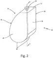
- FIG. 2 is a perspective view of conformable tank 18.
- Conformable tank 18 includes body 24 and port 26.
- Body 24 includes front wall 28, rear wall 30, top wall 32, bottom wall 34, curved side wall 36, and flat side wall 38.
- front wall 28, rear wall 30, and top wall 32 are shown as flat walls and bottom wall 34 is shown as a curved wall.
- front wall 28, rear wall 30, top wall 32 and bottom wall 34 can be flat walls, curved walls, or irregular shaped walls.
- Conformable tank 18 is made out of a continuous fiber filament reinforced composite that is produced using a fused deposition modeling process in the embodiment shown in FIG. 2 . In alternate embodiments, conformable tank 18 can be manufactured out of any suitable material using any suitable process. Conformable tank 18 includes body 24 that forms a housing for conformable tank 18. A fluid can be stored in body 24 of conformable tank 18. Port 26 extends through body 24 of conformable tank 18. Port 26 is an inlet/outlet for conformable tank 18 that allows a fluid to flow into and out of conformable tank 18. As conformable tank 18 is a pressurized tank, port 26 is used to allow the fluid to flow into and out of conformable tank 18 while maintaining the pressure in conformable tank 18. In alternate embodiments, other mechanisms can be used to allow the fluid to flow into and out of conformable tank 18.
- Body 24 of conformable tank 18 includes front wall 28 that is positioned opposite of rear wall 30, top wall 32 that is positioned opposite of bottom wall 34, and curved side wall 36 that is positioned opposite of flat side wall 38.
- Front wall 28 is in contact with and connects to top wall 32, bottom wall 34, curved side wall 36, and flat side wall 38.
- Rear wall 30 is in contact with and connects to top wall 32, bottom wall 34, curved side wall 36, and flat side wall 38.
- Top wall 32 extends between and connects to front wall 28, rear wall 30, curved side wall 36, and flat side wall 38.
- Bottom wall 34 extends between and connects to front wall 28, rear wall 30, curved side wall 36, and flat side wall 38.
- Curved side wall 36 is in contact with and connects to front wall 28, rear wall 30, top wall 32, and bottom wall 34.
- Flat side wall 38 is in contact with and connects to front wall 28, rear wall 30, top wall 32, and bottom wall 34.
- port 26 is situated on top wall 32.
- port 26 can be situated on any of the walls of body 24, such as front wall 28, rear wall 30, top wall 32, bottom wall 34, curved side wall 36, or flat side wall 38.
- Port 26 is configured to aid in filling and emptying conformable tank 18.
- conformable tank 18 is designed to store potable water for use on aircraft 10 as a part of potable water system 12 (shown in FIG. 1A ).
- Port 26 of conformable tank 18 can be connected by a tube to hydraulic pump 14A of potable water system 12, as shown in FIG. 1A .
- port 26 of conformable tank 18 can be connected by a tube to compressed air source 14B and control valve 16 of potable water system 12, as shown in FIG. 1B .
- FIG. 3A is a side cross-sectional view of a first embodiment of conformable tank 18 taken along line A-A of FIG. 2 .
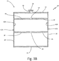
- FIG. 3B is a side cross-section view of the first embodiment of conformable tank 18 taken along line 3B-3B of FIG. 3A .
- Conformable tank 18 includes body 24 and port 26.
- Body 24 includes front wall 28, rear wall 30, top wall 32, bottom wall 34, curved side wall 36, and flat side wall 38.
- Front wall 28, rear wall 30, top wall 32, bottom wall 34, curved side wall 36, and flat side wall 38 include inner surfaces 40A, 40B, 40C, 40D, 40E, and 40F, and outer surfaces 42A, 42B, 42C, 42D, 42E, and 42F, respectively.
- Conformable tank 18 further includes first baffle 44, second baffle 46, first cavity 48, second cavity 50, third cavity 52, first aperture 54, second aperture 56, and third aperture 58.
- Conformable tank 18 includes body 24 that forms a housing of conformable tank 18. Port 26 extends through body 24 of conformable tank 18 to provide an inlet/outlet to conformable tank 18.
- Body 24 of conformable tank 18 includes front wall 28 that is positioned opposite of rear wall 30, top wall 32 that is positioned opposite of bottom wall 34, and curved side wall 36 that is positioned opposite of flat side wall 38.
- Front wall 28 includes inner surface 40A and outer surface 42A.
- Rear wall 30 includes inner surface 40B and outer surface 42B.
- Top wall 32 includes inner surface 40C and outer surface 42C.
- Bottom wall 34 includes inner surface 40D and outer surface 42D.
- Curved side wall 36 includes inner surface 40E and outer surface 42E.
- Flat side wall 38 includes inner surface 40F and outer surface 42F.
- Inner surfaces 40A, 40B, 40C, 40D, 40E, and 40F form an interior of conformable tank 18 and outer surfaces 42A, 42B, 42C, 42D, 42E, and 42F form an exterior of conformable tank 18.
- Conformable tank 18 further includes first baffle 44 and second baffle 46 extending through an interior of conformable tank 18.
- First baffle 44 extends from inner surface 40E of curved side wall 36 to inner surface 40F of flat side wall 38.
- First baffle 44 also extends from inner surface 40A of front wall 28 to inner surface 40B of rear wall 30.
- Second baffle 46 extends from inner surface 40E of curved side wall 36 to inner surface 40F of flat side wall 38.
- Second baffle 46 also extends from inner surface 40A of front wall 28 to inner surface 40B of rear wall 30.
- First baffle 44 and second baffle 46 divide the interior of conformable tank 18 into first cavity 48, second cavity 50, and third cavity 52.
- First cavity 48 is defined as the volume enclosed by front wall 28, rear wall 30, top wall 32, curved side wall 36, flat side wall 38, and first baffle 44.
- Second cavity 50 is defined as the volume enclosed by front wall 28, rear wall 30, curved side wall 36, flat side wall 38, first baffle 44, and second baffle 46.
- Third cavity 52 is defined as the volume enclosed by front wall 28, rear wall 30, bottom wall 34, curved side wall 36, and flat side wall 38, and second baffle 46.
- First cavity 48, second cavity 50, and third cavity 52 are configured to store potable water, or any other fluid, at an elevated pressure in conformable tank 18.
- first aperture 54 Extending through first baffle 44 and fluidly connecting first cavity 48 and second cavity 50 is first aperture 54. Extending through second baffle 46 and fluidly connecting second cavity 50 and third cavity 52 is second aperture 56.
- the embodiment shown in FIGS. 3A-3B shows a single aperture extending through each baffle. Alternate embodiments may include any number of apertures extending through each baffle. Further, the apertures can be of equal shape and size or varying shape and size.
- Conformable tank 18 is configured to store fluids, particularly potable water, at an elevated pressure when compared to ambient pressure outside conformable tank 18.
- the baffles within conformable tank 18 provide structural support to prevent excessive deformation from the internal pressure while still allowing fluid to pass from cavity to cavity.
- Conformable tank 18 can be designed to fit in and conform to a plurality of irregular aircraft spaces.
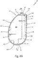
- FIG. 4A is a side cross-sectional view of a second embodiment of conformable tank 18 taken along line A-A of FIG. 2 .
- FIG. 4B is a side cross-sectional view of the second embodiment of conformable tank 18 taken along line 4B-4B of FIG. 4A .
- Conformable tank 18 includes body 24 and port 26.
- Body 24 includes front wall 28, rear wall 30, top wall 32, bottom wall 34, curved side wall 36, and flat side wall 38.
- Front wall 28, rear wall 30, top wall 32, bottom wall 34, curved side wall 36, and flat side wall 38 include inner surfaces 40A, 40B, 40C, 40D, 40E, and 40F, and outer surfaces 42A, 42B, 42C, 42D, 42E, and 42F, respectively.
- Conformable tank 18 further includes internal cavity 60, first rib 62, second rib 64, third rib 66, and fourth rib 68.
- Conformable tank 18 includes body 24 that forms a housing of conformable tank 18. Port 26 extends through body 24 of conformable tank 18 to provide an inlet/outlet to conformable tank 18.
- Body 24 of conformable tank 18 includes front wall 28 that is positioned opposite of rear wall 30, top wall 32 that is positioned opposite of bottom wall 34, and curved side wall 36 that is positioned opposite of flat side wall 38.
- Front wall 28 includes inner surface 40A and outer surface 42A.
- Rear wall 30 includes inner surface 40B and outer surface 42B.
- Top wall 32 includes inner surface 40C and outer surface 42C.
- Bottom wall 34 includes inner surface 40D and outer surface 42D.
- Curved side wall 36 includes inner surface 40E and outer surface 42E.
- Flat side wall 38 includes inner surface 40F and outer surface 42F.
- Inner surfaces 40A, 40B, 40C, 40D, 40E, and 40F form an interior of conformable tank 18 and outer surfaces 42A, 42B, 42C, 42D, 42E, and 42F form an exterior of conformable tank 18.
- Internal cavity 60 is formed in the interior of conformable tank 18.
- Conformable tank 18 includes first rib 62, second rib 64, third rib 66, and fourth rib 68 in cavity 60 to provide structural support for conformable tank 18.
- First rib 62 extends along inner surface 40B of rear wall 30 and abuts inner surface 40F of flat side wall 38 and protrudes into internal cavity 60.
- Second rib 64 extends along inner surface 40F of flat side wall 38 and protrudes into internal cavity 60.
- Third rib 66 extends along inner surface 40B of rear wall 30 and protrudes into internal cavity 60.
- Fourth rib 68 extends from inner surface 40D of bottom wall 34 and protrudes into internal cavity 60.
- conformable tank 18 with ribs utilized as internal supports.
- the ribs provide structural support to conformable tank 18 and prevent it from deforming excessively under internal pressure.
- conformable tank 18 can include a plurality of ribs of varying shapes and sizes.
- the ribs can connect to any of the walls of body 24 and extend along or protrude from the walls in any suitable manner.
- Conformable tank 18 is configured to store fluids, particularly potable water, at an elevated pressure when compared to ambient pressure outside conformable tank 18.
- the ribs within conformable tank 18 provide structural support to prevent excessive deformation from the internal pressure while still allowing fluid flow within the internal cavity.
- Conformable tank 18 can be designed to fit in and conform to a plurality of irregular aircraft spaces.
- Step 100 includes loading a 3D computer aided design (CAD) file with a model of a part that is to be additively manufactured into computer software.
- the 3D CAD file can include a model of conformable tank 18 that is to be additively manufactured.
- Step 102 includes slicing the model of the 3D CAD file into a plurality of layers. The layers do not need to be parallel to each other. This includes slicing the model of conformable tank 18 into a plurality of layers. The plurality of layers of conformable tank 18 will be additively manufactured.
- Step 104 includes communicating the model of the 3D CAD file that has been sliced into a plurality of layers to an additive manufacturing machine. This includes communicating the model for conformable tank 18 that has been sliced into a plurality of layers to an additive manufacturing machine.
- Step 108 includes depositing a fiber filament into each layer of the part as the part is additively manufactured.
- another nozzle feeds a fiber filament.
- the fiber filament is fed to the same location as the composite material, creating a fiber filament covered by a composite material known as a fiber filament reinforced composite.
- the additive manufacturing process is described as utilizing two separate nozzles to deposit the composite and the fiber filament, but in another method one nozzle can deposit both the composite and the fiber filament simultaneously.
- the fiber filament used to reinforce the composite material can be fiberglass, carbon fiber, synthetic fiber (such as Kevlar®), or other materials known to a person skilled in the art.
- the fiber filament is added to the composite to improve the material properties of the part, including but not limited to strength, toughness, impact resistant, and temperature resistance.
- a conformable tank includes a body with a plurality of walls defining a cavity in the body, and an internal support connected to an internal surface of one of the plurality of walls of the body and protruding into the cavity of the body.
- the body and the internal support are an additively manufactured integral structure formed by a fiber filament reinforced composite material.
- the additive manufacturing process is a fused deposition modeling process.
- the fiber filament reinforced composite material includes a fiber filament in a composite material.
- the fiber filament is selected from the group consisting of fiberglass, carbon, synthetic fiber, and combinations thereof.
- an aperture extends through one of the plurality of walls of the body.
- a port is positioned in the aperture extending through one of the plurality of walls of the body.
- the plurality of walls includes a flat side wall that includes an inner surface and an outer surface; a curved side wall that includes an inner surface and an outer surface; a top wall that includes an inner surface and an outer surface, wherein the top wall extends between and connects the flat side wall and the curved side wall; a bottom wall that includes an inner surface and an outer surface, wherein the bottom wall extends between and connects the flat side wall and the curved side wall; a front wall that includes an inner surface and an outer surface, wherein the front wall contacts and connects the flat side wall, the curved side wall, the top wall, and the bottom wall; and a rear wall that includes an inner surface and an outer surface, wherein the rear wall contacts and connects the flat side wall, the curved side wall, the top wall, and the bottom wall.
- the curved side wall of the conformable tank is configured to conform to an aircraft fuselage.
- the internal support is a rib that is connected to at least one of the plurality of walls of the body, and wherein the rib extends into the internal cavity.
- the conformable tank is configured to store potable water.
- the method of the preceding paragraph can optionally include, additionally and/or alternatively, any one or more of the following features, configurations and/or additional components:
- additively manufacturing the conformable tank includes additively manufacturing the conformable tank using a fused deposition modeling process.
- the fiber filament is selected from the group consisting of fiberglass, carbon, synthetic fiber, and combinations thereof.
- additively manufacturing the conformable tank includes additively manufacturing the conformable tank out of a composite material.
- additively manufacturing the conformable tank includes feeding a filament of composite material into an extrusion nozzle; melting the filament of composite material; and extruding the melted composite material onto a working surface.
- the conformable tank includes a body with a plurality of walls defining a cavity in the body; and an internal support connected to an internal surface of one of the plurality of wall of the body and protruding into the cavity of the body.
- the plurality of walls of the conformable tank includes a flat side wall that includes an inner surface and an outer surface; a curved side wall that includes an inner surface and an outer surface; a top wall that includes an inner surface and an outer surface, wherein the top wall extends between and connects the flat side wall and the curved side wall; a bottom wall that includes an inner surface and an outer surface, wherein the bottom wall extends between and connects the flat side wall and the curved side wall; a front wall that includes an inner surface and an outer surface, wherein the front wall contacts and connects the flat side wall, the curved side wall, the top wall, and the bottom wall; and a rear wall that includes an inner surface and an outer surface, wherein the rear wall contacts and connects the flat side wall, the curved side wall, the top wall, and the bottom wall.
Landscapes
- Engineering & Computer Science (AREA)
- Chemical & Material Sciences (AREA)
- Materials Engineering (AREA)
- Aviation & Aerospace Engineering (AREA)
- Manufacturing & Machinery (AREA)
- Mechanical Engineering (AREA)
- Physics & Mathematics (AREA)
- Optics & Photonics (AREA)
- Moulding By Coating Moulds (AREA)
- Filling Or Discharging Of Gas Storage Vessels (AREA)
Abstract
Description
- The present invention relates generally to pressurized tanks, and more particularly to pressurized tanks used on an aircraft for potable water.
- The aircraft industry currently employs pressurized tanks constructed of dense metal alloys to transport and make use of potable water on board an aircraft. Potable water on an aircraft may be used for direct human consumption, food preparation, hygienic activities, and sanitation. For example, water may be used for the preparation of hot and cold beverages for consumption, reconstituting dehydrated foods, ingestion from cold water taps or water fountains, brushing of teeth, hand washing, cleaning of utensils, lavatory use, and onboard showering facilities.
- In general, any tank for use in an aircraft is subjected to pressure, vibration, flight loads, and shock stresses. The pressure, in particular, can create large bending stresses on flat walls of the tanks. Metal tanks have internal bracing to support various sections and joints that are under such stresses, especially those portions with flat walls and sharp corners. However, metal tanks are relatively heavy. The higher the total weight of an aircraft the more fuel that is required to fly. Thus, it is desirable to find a lightweight conformable tank which can withstand the pressure, vibration, flight loads, and shock stresses encountered on board an aircraft to improve its fuel efficiency.
- A conformable tank includes a body with a plurality of walls defining a cavity in the body, and an internal support connected to an internal surface of one of the plurality of walls of the body and protruding into the cavity of the body. The body and the internal support are an additively manufactured integral structure formed by a fiber filament reinforced composite material.
- A method of manufacturing a conformable tank including loading a CAD file with a model of a conformable tank that is to be additively manufactured into computer software. The model of the conformable tank is sliced into a plurality of layers using the computer software. The model that has been sliced into a plurality of layers is communicated to an additive manufacturing machine. The conformable tank is additively manufactured layer-by-layer with a fiber filament in each layer of the conformable tank.
-
-
FIG. 1A is a schematic of an aircraft with a first embodiment of a potable water system. -
FIG. 1B is a schematic of an aircraft with a second embodiment of a potable water system. -
FIG. 1C is a cross-sectional view of an aircraft fuselage, showing a conformable tank. -
FIG. 2 is a perspective view of the conformable tank ofFIG. 1C . -
FIG. 3A is a side cross-sectional view of a first embodiment of the conformable tank taken along line A-A ofFIG. 2 . -
FIG. 3B is a side cross-section view of the first embodiment of the conformable tank taken alongline 3B-3B ofFIG. 3A . -
FIG. 4A is a side cross-sectional view of a second embodiment of the conformable tank taken along line A-A ofFIG. 2 . -
FIG. 4B is a side cross-sectional view of the second embodiment of the conformable tank taken alongline 4B-4B ofFIG. 4A . -
FIG. 5 is a flow chart showing a method of manufacturing the conformable tank ofFIG. 2 . -
FIG. 1A is a schematic ofaircraft 10 with a first embodiment ofpotable water system 12, which includeshydraulic pump 14A,control valve 16, point ofuse 17, andconformable tank 18.FIG. 1B is a schematic ofaircraft 10 with a second embodiment ofpotable water system 12, which includescompressed air source 14B,control valve 16, point ofuse 17, andconformable tank 18.FIG. 1C is a cross-sectional view ofaircraft 10, showingconformable tank 18,fuselage 20, andinternal structure 22. - Situated in an aft portion of
aircraft 10 ispotable water system 12. In the first embodiment shown inFIG. 1A ,potable water system 12 includeshydraulic pump 14A,control valve 16, point ofuse 17, andconformable tank 18 that are connected to one another by hydraulic tubes, lines, or hoses. Fluid flow withinpotable water system 12 is induced usinghydraulic pump 14A. Fluid flow withinpotable water system 12 is controlled usingcontrol valve 16. Potable water for use inpotable water system 12 is stored inconformable tank 18. In the embodiment shown inFIG. 1B ,potable water system 12 includescompressed air source 14B,control valve 16, point ofuse 17, andconformable tank 18 that are connected to one another by hydraulic tubes, lines, or hoses. Fluid flow withinpotable water system 12 is induced bycompressed air source 14B. Fluid flow withinpotable water system 12 is controlled usingcontrol valve 16. Potable water for use inpotable water system 12 is stored inconformable tank 18 at an elevated pressure, as compared to ambient pressure outsideconformable tank 18. - As shown in
FIG. 1C ,conformable tank 18 is configured to conform to bothfuselage 20 andinternal structure 22. A curved wall on a first side ofconformable tank 18 is configured to conform to the curvature offuselage 20. Likewise, a flat wall on a second side ofconformable tank 18 opposite of the curved wall is configured to conform tointernal structure 22.FIG. 1C shows one embodiment ofconformable tank 18 and is not meant to limit the disclosure to a single embodiment.Conformable tank 18 is conformable for use in a plurality of irregular aircraft spaces. The following description details two possible embodiments ofconformable tank 18. -
FIG. 2 is a perspective view ofconformable tank 18.Conformable tank 18 includesbody 24 andport 26.Body 24 includesfront wall 28,rear wall 30,top wall 32,bottom wall 34,curved side wall 36, andflat side wall 38. In the embodiment shown inFIG. 2 ,front wall 28,rear wall 30, andtop wall 32 are shown as flat walls andbottom wall 34 is shown as a curved wall. In alternate embodiments,front wall 28,rear wall 30,top wall 32 andbottom wall 34 can be flat walls, curved walls, or irregular shaped walls. -
Conformable tank 18 is made out of a continuous fiber filament reinforced composite that is produced using a fused deposition modeling process in the embodiment shown inFIG. 2 . In alternate embodiments,conformable tank 18 can be manufactured out of any suitable material using any suitable process.Conformable tank 18 includesbody 24 that forms a housing forconformable tank 18. A fluid can be stored inbody 24 ofconformable tank 18.Port 26 extends throughbody 24 ofconformable tank 18.Port 26 is an inlet/outlet forconformable tank 18 that allows a fluid to flow into and out ofconformable tank 18. Asconformable tank 18 is a pressurized tank,port 26 is used to allow the fluid to flow into and out ofconformable tank 18 while maintaining the pressure inconformable tank 18. In alternate embodiments, other mechanisms can be used to allow the fluid to flow into and out ofconformable tank 18. -
Body 24 ofconformable tank 18 includesfront wall 28 that is positioned opposite ofrear wall 30,top wall 32 that is positioned opposite ofbottom wall 34, andcurved side wall 36 that is positioned opposite offlat side wall 38.Front wall 28 is in contact with and connects totop wall 32,bottom wall 34,curved side wall 36, andflat side wall 38.Rear wall 30 is in contact with and connects totop wall 32,bottom wall 34,curved side wall 36, andflat side wall 38.Top wall 32 extends between and connects tofront wall 28,rear wall 30,curved side wall 36, andflat side wall 38.Bottom wall 34 extends between and connects tofront wall 28,rear wall 30,curved side wall 36, andflat side wall 38.Curved side wall 36 is in contact with and connects tofront wall 28,rear wall 30,top wall 32, andbottom wall 34.Flat side wall 38 is in contact with and connects tofront wall 28,rear wall 30,top wall 32, andbottom wall 34. - In the embodiment shown in
FIG. 2 ,port 26 is situated ontop wall 32. In alternate embodiments,port 26 can be situated on any of the walls ofbody 24, such asfront wall 28,rear wall 30,top wall 32,bottom wall 34,curved side wall 36, orflat side wall 38. Further, in the embodiment shown inFIG. 2 there is only oneport 26. In alternate embodiments, there can be a plurality ofport 26, extending through the same wall or different walls ofbody 24.Port 26 is configured to aid in filling and emptyingconformable tank 18. In the embodiment shown inFIG. 2 ,conformable tank 18 is designed to store potable water for use onaircraft 10 as a part of potable water system 12 (shown inFIG. 1A ).Port 26 ofconformable tank 18 can be connected by a tube tohydraulic pump 14A ofpotable water system 12, as shown inFIG. 1A . Likewise,port 26 ofconformable tank 18 can be connected by a tube tocompressed air source 14B andcontrol valve 16 ofpotable water system 12, as shown inFIG. 1B . -
FIG. 3A is a side cross-sectional view of a first embodiment ofconformable tank 18 taken along line A-A ofFIG. 2 .FIG. 3B is a side cross-section view of the first embodiment ofconformable tank 18 taken alongline 3B-3B ofFIG. 3A .Conformable tank 18 includesbody 24 andport 26.Body 24 includesfront wall 28,rear wall 30,top wall 32,bottom wall 34,curved side wall 36, andflat side wall 38.Front wall 28,rear wall 30,top wall 32,bottom wall 34,curved side wall 36, andflat side wall 38 includeinner surfaces outer surfaces Conformable tank 18 further includesfirst baffle 44,second baffle 46,first cavity 48,second cavity 50,third cavity 52,first aperture 54,second aperture 56, andthird aperture 58. -
Conformable tank 18 includesbody 24 that forms a housing ofconformable tank 18.Port 26 extends throughbody 24 ofconformable tank 18 to provide an inlet/outlet toconformable tank 18.Body 24 ofconformable tank 18 includesfront wall 28 that is positioned opposite ofrear wall 30,top wall 32 that is positioned opposite ofbottom wall 34, andcurved side wall 36 that is positioned opposite offlat side wall 38. -
Front wall 28 includesinner surface 40A andouter surface 42A.Rear wall 30 includesinner surface 40B andouter surface 42B.Top wall 32 includesinner surface 40C andouter surface 42C.Bottom wall 34 includesinner surface 40D andouter surface 42D.Curved side wall 36 includesinner surface 40E andouter surface 42E.Flat side wall 38 includesinner surface 40F andouter surface 42F.Inner surfaces conformable tank 18 andouter surfaces conformable tank 18. -
Conformable tank 18 further includesfirst baffle 44 andsecond baffle 46 extending through an interior ofconformable tank 18.First baffle 44 extends frominner surface 40E ofcurved side wall 36 toinner surface 40F offlat side wall 38.First baffle 44 also extends frominner surface 40A offront wall 28 toinner surface 40B ofrear wall 30.Second baffle 46 extends frominner surface 40E ofcurved side wall 36 toinner surface 40F offlat side wall 38.Second baffle 46 also extends frominner surface 40A offront wall 28 toinner surface 40B ofrear wall 30. -
First baffle 44 andsecond baffle 46 are configured to act as internal supports and provide structural support tobody 24 ofconformable tank 18. Withoutfirst baffle 44 andsecond baffle 46,conformable tank 18 could deform under internal pressure. In the embodiment shown,conformable tank 18 includes two baffles. In alternate embodiments,conformable tank 18 can include any number of baffles. -
First baffle 44 andsecond baffle 46 divide the interior ofconformable tank 18 intofirst cavity 48,second cavity 50, andthird cavity 52.First cavity 48 is defined as the volume enclosed byfront wall 28,rear wall 30,top wall 32,curved side wall 36,flat side wall 38, andfirst baffle 44.Second cavity 50 is defined as the volume enclosed byfront wall 28,rear wall 30,curved side wall 36,flat side wall 38,first baffle 44, andsecond baffle 46.Third cavity 52 is defined as the volume enclosed byfront wall 28,rear wall 30,bottom wall 34,curved side wall 36, andflat side wall 38, andsecond baffle 46.First cavity 48,second cavity 50, andthird cavity 52 are configured to store potable water, or any other fluid, at an elevated pressure inconformable tank 18. - Extending through
first baffle 44 and fluidly connectingfirst cavity 48 andsecond cavity 50 isfirst aperture 54. Extending throughsecond baffle 46 and fluidly connectingsecond cavity 50 andthird cavity 52 issecond aperture 56. The embodiment shown inFIGS. 3A-3B shows a single aperture extending through each baffle. Alternate embodiments may include any number of apertures extending through each baffle. Further, the apertures can be of equal shape and size or varying shape and size. - Extending through
top wall 32 isthird aperture 58.Third aperture 58 provides a means for filling and emptyingconformable tank 18.Third aperture 58 can be fitted withport 26 or any other component used to aid in filling and emptyingconformable tank 18. According to the embodiment shown inFIGS. 3A-3B ,third aperture 58 extends throughtop wall 32. In alternate embodiments,third aperture 58 can extend through any of the walls ofbody 24, such asfront wall 28,rear wall 30,top wall 32,bottom wall 34,curved side wall 36, orflat side wall 38. -
Conformable tank 18 is configured to store fluids, particularly potable water, at an elevated pressure when compared to ambient pressure outsideconformable tank 18. The baffles withinconformable tank 18 provide structural support to prevent excessive deformation from the internal pressure while still allowing fluid to pass from cavity to cavity.Conformable tank 18 can be designed to fit in and conform to a plurality of irregular aircraft spaces. -
FIG. 4A is a side cross-sectional view of a second embodiment ofconformable tank 18 taken along line A-A ofFIG. 2 .FIG. 4B is a side cross-sectional view of the second embodiment ofconformable tank 18 taken alongline 4B-4B ofFIG. 4A .Conformable tank 18 includesbody 24 andport 26.Body 24 includesfront wall 28,rear wall 30,top wall 32,bottom wall 34,curved side wall 36, andflat side wall 38.Front wall 28,rear wall 30,top wall 32,bottom wall 34,curved side wall 36, andflat side wall 38 includeinner surfaces outer surfaces Conformable tank 18 further includesinternal cavity 60,first rib 62,second rib 64,third rib 66, andfourth rib 68. -
Conformable tank 18 includesbody 24 that forms a housing ofconformable tank 18.Port 26 extends throughbody 24 ofconformable tank 18 to provide an inlet/outlet toconformable tank 18.Body 24 ofconformable tank 18 includesfront wall 28 that is positioned opposite ofrear wall 30,top wall 32 that is positioned opposite ofbottom wall 34, andcurved side wall 36 that is positioned opposite offlat side wall 38. -
Front wall 28 includesinner surface 40A andouter surface 42A.Rear wall 30 includesinner surface 40B andouter surface 42B.Top wall 32 includesinner surface 40C andouter surface 42C.Bottom wall 34 includesinner surface 40D andouter surface 42D.Curved side wall 36 includesinner surface 40E andouter surface 42E.Flat side wall 38 includesinner surface 40F andouter surface 42F.Inner surfaces conformable tank 18 andouter surfaces conformable tank 18.Internal cavity 60 is formed in the interior ofconformable tank 18. -
Conformable tank 18 includesfirst rib 62,second rib 64,third rib 66, andfourth rib 68 incavity 60 to provide structural support forconformable tank 18.First rib 62 extends alonginner surface 40B ofrear wall 30 and abutsinner surface 40F offlat side wall 38 and protrudes intointernal cavity 60.Second rib 64 extends alonginner surface 40F offlat side wall 38 and protrudes intointernal cavity 60.Third rib 66 extends alonginner surface 40B ofrear wall 30 and protrudes intointernal cavity 60.Fourth rib 68 extends frominner surface 40D ofbottom wall 34 and protrudes intointernal cavity 60. - The embodiment shown in
FIGS. 4A-4B is one embodiment ofconformable tank 18 with ribs utilized as internal supports. The ribs provide structural support toconformable tank 18 and prevent it from deforming excessively under internal pressure. This embodiment is not meant to limit the disclosure to a single embodiment. In alternate embodiments,conformable tank 18 can include a plurality of ribs of varying shapes and sizes. The ribs can connect to any of the walls ofbody 24 and extend along or protrude from the walls in any suitable manner. -
Conformable tank 18 is configured to store fluids, particularly potable water, at an elevated pressure when compared to ambient pressure outsideconformable tank 18. The ribs withinconformable tank 18 provide structural support to prevent excessive deformation from the internal pressure while still allowing fluid flow within the internal cavity.Conformable tank 18 can be designed to fit in and conform to a plurality of irregular aircraft spaces. -
FIG. 5 is a flow chart showing a method of manufacturingconformable tank 18. The flow chart includes steps 100-108. - Step 100 includes loading a 3D computer aided design (CAD) file with a model of a part that is to be additively manufactured into computer software. The 3D CAD file can include a model of
conformable tank 18 that is to be additively manufactured. Step 102 includes slicing the model of the 3D CAD file into a plurality of layers. The layers do not need to be parallel to each other. This includes slicing the model ofconformable tank 18 into a plurality of layers. The plurality of layers ofconformable tank 18 will be additively manufactured. Step 104 includes communicating the model of the 3D CAD file that has been sliced into a plurality of layers to an additive manufacturing machine. This includes communicating the model forconformable tank 18 that has been sliced into a plurality of layers to an additive manufacturing machine. - Step 106 includes additively manufacturing the part layer-by-layer. This includes additively manufacturing
conformable tank 18 layer-by-layer.Conformable tank 18 can be manufactured according to an additive manufacturing process such as fused deposition modeling. The fused deposition modeling process includes the following. A filament of composite material is fed through and heated in an extrusion nozzle, melting the composite material. The melted composite material is extruded from the extrusion nozzle and deposited on a working surface in a single layer. Once the composite material is on the working surface it hardens to form a solidified layer. Either the extrusion nozzle or the working surface moves relative to the other to provide space to deposit a subsequent layer on the previously deposited layer. Layer after layer, the composite material is deposited until the final 3D part is produced. - Step 108 includes depositing a fiber filament into each layer of the part as the part is additively manufactured. At the same time that the composite material is being fed through and heated in the extrusion nozzle, another nozzle feeds a fiber filament. The fiber filament is fed to the same location as the composite material, creating a fiber filament covered by a composite material known as a fiber filament reinforced composite. The additive manufacturing process is described as utilizing two separate nozzles to deposit the composite and the fiber filament, but in another method one nozzle can deposit both the composite and the fiber filament simultaneously. The fiber filament used to reinforce the composite material can be fiberglass, carbon fiber, synthetic fiber (such as Kevlar®), or other materials known to a person skilled in the art. The fiber filament is added to the composite to improve the material properties of the part, including but not limited to strength, toughness, impact resistant, and temperature resistance.
- Traditionally, pressurized tanks for use on aircraft have been produced using metal alloys and standard manufacturing practices. This produces fairly heavy tanks that are costly to produce for complex geometry. The present disclosure creates
conformable tank 18 that is made out of a potable water safe composite material and is manufactured using additive manufacturing technology. Using a composite material is advantageous because it results in lighter weight pressurized tanks when compared to traditional metal alloy tanks. Using additive manufacturing to produce the pressurized tanks is beneficial because it allows for complex geometry to be produced for specific aircraft shape, space, and size requirements. Further, using additive manufacturing to produce the pressurized tanks for complex geometry is cost effective when compared to traditional manufacturing methods for both carbon-epoxy composites and metal alloys, because it requires less tooling and much less labor. Producingconformable tank 18 using a continuous fiber filament reinforced composite according to the fused deposition modeling process results in a highly conformable, lightweight, and inexpensive pressurized tank that can be used to store potable water in irregular shaped aircraft spaces. - The following are non-exclusive descriptions of possible embodiments of the present invention.
- A conformable tank includes a body with a plurality of walls defining a cavity in the body, and an internal support connected to an internal surface of one of the plurality of walls of the body and protruding into the cavity of the body. The body and the internal support are an additively manufactured integral structure formed by a fiber filament reinforced composite material.
- The conformable tank of the preceding paragraph can optionally include, additionally and/or alternatively, any one or more of the following features, configurations and/or additional components:
- Wherein the additive manufacturing process is a fused deposition modeling process.
- Wherein the fiber filament reinforced composite material includes a fiber filament in a composite material.
- Wherein the fiber filament is selected from the group consisting of fiberglass, carbon, synthetic fiber, and combinations thereof.
- Wherein an aperture extends through one of the plurality of walls of the body.
- Wherein a port is positioned in the aperture extending through one of the plurality of walls of the body.
- Wherein the plurality of walls includes a flat side wall that includes an inner surface and an outer surface; a curved side wall that includes an inner surface and an outer surface; a top wall that includes an inner surface and an outer surface, wherein the top wall extends between and connects the flat side wall and the curved side wall;a bottom wall that includes an inner surface and an outer surface, wherein the bottom wall extends between and connects the flat side wall and the curved side wall;a front wall that includes an inner surface and an outer surface, wherein the front wall contacts and connects the flat side wall, the curved side wall, the top wall, and the bottom wall; and a rear wall that includes an inner surface and an outer surface, wherein the rear wall contacts and connects the flat side wall, the curved side wall, the top wall, and the bottom wall.
- Wherein the curved side wall of the conformable tank is configured to conform to an aircraft fuselage.
- Wherein the internal support is a baffle that extends across the conformable tank from the inner surface of the flat side wall to the inner surface of the curved side wall, and wherein the baffle extends across the conformable tank from the inner surface of the rear wall to the inner surface of the front wall.
- Wherein the baffle creates a first internal cavity that is defined by the inner surface of the bottom wall, the inner surface of the flat side wall, the inner surface of the curved side wall, and the baffle and a second internal cavity that is defined by the inner surface of the top wall, the inner surface of the flat side wall, the inner surface of the curved side wall, and the baffle.
- Wherein an aperture extends through the baffle to allow fluid connection between the first internal cavity and the second internal cavity.
- Wherein the internal support is a rib that is connected to at least one of the plurality of walls of the body, and wherein the rib extends into the internal cavity.
- Wherein the conformable tank is configured to store potable water.
- A method of manufacturing a conformable tank including loading a CAD file with a model of a conformable tank that is to be additively manufactured into computer software. The model of the conformable tank is sliced into a plurality of layers using the computer software. The model that has been sliced into a plurality of layers is communicated to an additive manufacturing machine. The conformable tank is additively manufactured layer-by-layer with a fiber filament in each layer of the conformable tank.
- The method of the preceding paragraph can optionally include, additionally and/or alternatively, any one or more of the following features, configurations and/or additional components:
- Wherein additively manufacturing the conformable tank includes additively manufacturing the conformable tank using a fused deposition modeling process.
- Wherein the fiber filament is selected from the group consisting of fiberglass, carbon, synthetic fiber, and combinations thereof.
- Wherein additively manufacturing the conformable tank includes additively manufacturing the conformable tank out of a composite material.
- Wherein additively manufacturing the conformable tank includes feeding a filament of composite material into an extrusion nozzle; melting the filament of composite material; and extruding the melted composite material onto a working surface.
- Wherein the conformable tank includes a body with a plurality of walls defining a cavity in the body; and an internal support connected to an internal surface of one of the plurality of wall of the body and protruding into the cavity of the body.
- Wherein the plurality of walls of the conformable tank includes a flat side wall that includes an inner surface and an outer surface; a curved side wall that includes an inner surface and an outer surface; a top wall that includes an inner surface and an outer surface, wherein the top wall extends between and connects the flat side wall and the curved side wall; a bottom wall that includes an inner surface and an outer surface, wherein the bottom wall extends between and connects the flat side wall and the curved side wall; a front wall that includes an inner surface and an outer surface, wherein the front wall contacts and connects the flat side wall, the curved side wall, the top wall, and the bottom wall; and a rear wall that includes an inner surface and an outer surface, wherein the rear wall contacts and connects the flat side wall, the curved side wall, the top wall, and the bottom wall.
- While the invention has been described with reference to an exemplary embodiment(s), it will be understood by those skilled in the art that various changes may be made and equivalents may be substituted for elements thereof without departing from the scope of the invention. In addition, many modifications may be made to adapt a particular situation or material to the teachings of the invention without departing from the scope thereof as defined by the claims. Therefore, it is intended that the invention not be limited to the particular embodiment(s) disclosed, but that the invention will include all embodiments falling within the scope of the appended claims.
Claims (15)
- A conformable tank comprising:a body (24) with a plurality of walls defining a cavity (60) in the body; andan internal support (44) connected to an internal surface of one of the plurality of walls of the body and protruding into the cavity of the body;wherein the body and the internal support are an additively manufactured integral structure formed by a fiber filament reinforced composite material.
- The conformable tank of claim 1 or 2, wherein the additive manufacturing process is a fused deposition modeling process.
- The conformable tank of claim 1, wherein the fiber filament reinforced composite material includes a fiber filament in a composite material, and preferably wherein the fiber filament is selected from the group consisting of fiberglass, carbon, synthetic fiber, and combinations thereof.
- The conformable tank of claim 1, 2 or 3, wherein an aperture extends through one of the plurality of walls of the body, and preferably wherein a port (26) is positioned in the aperture extending through one of the plurality of walls of the body.
- The conformable tank of any preceding claim, wherein the plurality of walls comprises:a flat side wall (38) that includes an inner surface and an outer surface;a curved side wall (36) that includes an inner surface and an outer surface;a top wall (32) that includes an inner surface and an outer surface, wherein the top wall extends between and connects the flat side wall and the curved side wall;a bottom wall (34) that includes an inner surface and an outer surface, wherein the bottom wall extends between and connects the flat side wall and the curved side wall;a front wall (28) that includes an inner surface and an outer surface, wherein the front wall contacts and connects the flat side wall, the curved side wall, the top wall, and the bottom wall; anda rear wall (30) that includes an inner surface and an outer surface, wherein the rear wall contacts and connects the flat side wall, the curved side wall, the top wall, and the bottom wall.
- The conformable tank of claim 5, wherein the curved side wall of the conformable tank is configured to conform to an aircraft fuselage.
- The conformable tank of claim 5, wherein the internal support is a baffle (44) that extends across the conformable tank from the inner surface of the flat side wall to the inner surface of the curved side wall, and wherein the baffle extends across the conformable tank from the inner surface of the rear wall to the inner surface of the front wall.
- The conformable tank of claim 7, wherein the baffle creates a first internal cavity that is defined by the inner surface of the bottom wall, the inner surface of the flat side wall, the inner surface of the curved side wall, and the baffle and a second internal cavity that is defined by the inner surface of the top wall, the inner surface of the flat side wall, the inner surface of the curved side wall, and the baffle.
- The conformable tank of claim 8, wherein an aperture extends through the baffle to allow fluid connection between the first internal cavity and the second internal cavity.
- The conformable tank of any of claims 1 to 6, wherein the internal support is a rib (62) that is connected to at least one of the plurality of walls of the body, and wherein the rib extends into the internal cavity (60).
- A method of manufacturing a conformable tank, the method comprising:loading a CAD file with a model of a conformable tank that is to be additively manufactured into computer software;slicing the model of the conformable tank into a plurality of layers using the computer software;communicating the model that has been sliced into a plurality of layers to an additive manufacturing machine; andadditively manufacturing the conformable tank layer-by-layer with a fiber filament in each layer of the conformable tank.
- The method of claim 11, wherein additively manufacturing the conformable tank includes additively manufacturing the conformable tank using a fused deposition modeling process, and/or wherein additively manufacturing the conformable tank includes additively manufacturing the conformable tank out of a composite material.
- The method of claim 11 or 12, wherein the fiber filament is selected from the group consisting of fiberglass, carbon, synthetic fiber, and combinations thereof.
- The method of any of claims 11 to 13, wherein additively manufacturing the conformable tank further comprises:feeding a filament of composite material into an extrusion nozzle;melting the filament of composite material; andextruding the melted composite material onto a working surface.
- The method of any of claims 11 to 14, wherein the conformable tank comprises:
a body with a plurality of walls defining a cavity in the body; and
an internal support connected to an internal surface of one of the plurality of wall of the body and protruding into the cavity of the body.
Applications Claiming Priority (1)
| Application Number | Priority Date | Filing Date | Title |
|---|---|---|---|
| US15/689,599 US11091266B2 (en) | 2017-08-29 | 2017-08-29 | Conformable tank fabricated using additive manufacturing |
Publications (2)
| Publication Number | Publication Date |
|---|---|
| EP3450321A1 true EP3450321A1 (en) | 2019-03-06 |
| EP3450321B1 EP3450321B1 (en) | 2020-07-29 |
Family
ID=63491400
Family Applications (1)
| Application Number | Title | Priority Date | Filing Date |
|---|---|---|---|
| EP18191294.0A Active EP3450321B1 (en) | 2017-08-29 | 2018-08-28 | Conformable tank fabricated using additive manufacturing |
Country Status (4)
| Country | Link |
|---|---|
| US (1) | US11091266B2 (en) |
| EP (1) | EP3450321B1 (en) |
| BR (1) | BR102018016213B1 (en) |
| CA (1) | CA3013018A1 (en) |
Cited By (2)
| Publication number | Priority date | Publication date | Assignee | Title |
|---|---|---|---|---|
| EP4134299A1 (en) * | 2021-08-13 | 2023-02-15 | The Boeing Company | Fuel dams, aircraft wing boxes, aircraft, and methods of assembling aircraft wings |
| EP4349569A1 (en) * | 2022-10-07 | 2024-04-10 | Rohr, Inc. | Manufacturing thermoplastic container with internal baffle(s) |
Families Citing this family (5)
| Publication number | Priority date | Publication date | Assignee | Title |
|---|---|---|---|---|
| US10703481B2 (en) | 2017-08-29 | 2020-07-07 | Goodrich Corporation | Conformable tank with sandwich structure walls |
| US11091266B2 (en) * | 2017-08-29 | 2021-08-17 | Goodrich Corporation | Conformable tank fabricated using additive manufacturing |
| US11939105B2 (en) | 2017-08-29 | 2024-03-26 | Goodrich Corporation | 3D woven conformable tank |
| US10816138B2 (en) | 2017-09-15 | 2020-10-27 | Goodrich Corporation | Manufacture of a conformable pressure vessel |
| US11724442B2 (en) * | 2018-07-12 | 2023-08-15 | Response Technologies, Llc | Process of manufacturing reticulated foam products, using alternative materials |
Citations (6)
| Publication number | Priority date | Publication date | Assignee | Title |
|---|---|---|---|---|
| US3447768A (en) * | 1967-02-08 | 1969-06-03 | Whittaker Corp | Lifting body external fuel stores |
| US5845879A (en) * | 1995-12-28 | 1998-12-08 | Lockheed Martin Corporation | Inflatable conformable fuel tank |
| US5927651A (en) * | 1997-05-15 | 1999-07-27 | Mcdonnell Douglas | Expandable fuel cell |
| EP2942285A1 (en) * | 2014-05-07 | 2015-11-11 | BAE Systems PLC | Liquid storage tank and baffle system |
| US20160361869A1 (en) * | 2013-03-22 | 2016-12-15 | Markforged, Inc. | Three dimensional printer for fiber reinforced composite filament fabrication |
| WO2017091222A1 (en) * | 2015-11-25 | 2017-06-01 | United Technologies Corporation | Composite pressure vessel assembly and method of manufacturing |
Family Cites Families (140)
| Publication number | Priority date | Publication date | Assignee | Title |
|---|---|---|---|---|
| US2731938A (en) * | 1956-01-24 | Fuel tank gage | ||
| DE299677C (en) * | ||||
| US1499817A (en) * | 1920-12-09 | 1924-07-01 | Fokker Anthony Herman Gerard | Arrangement and disposition of fuel tanks in flying machines |
| US1553122A (en) * | 1922-03-29 | 1925-09-08 | Thomas Morse Aircraft Corp | Airplane |
| US1507527A (en) * | 1924-01-14 | 1924-09-02 | Strine Archie Bryan | Flying machine |
| US1640471A (en) | 1926-06-02 | 1927-08-30 | Earl B Staley | Tank |
| US1835370A (en) * | 1928-11-27 | 1931-12-08 | Guiseppe M Bellanca | Airplane fuel tank |
| US1816130A (en) * | 1929-06-07 | 1931-07-28 | Sikorsky Aviat Corp | Aircraft including wing panel and fuel tank assembly for same |
| US1870595A (en) * | 1931-01-19 | 1932-08-09 | Gen Aviat Corp | Aeroplane structure |
| US1894675A (en) * | 1931-04-04 | 1933-01-17 | Albert C Dixon | Fuel tank |
| US1969200A (en) * | 1931-09-04 | 1934-08-07 | Giuseppe M Bellanca | Wing structure |
| US2401625A (en) * | 1940-04-13 | 1946-06-04 | Us Rubber Co | Method of making puncture sealing material |
| US2377722A (en) * | 1940-04-19 | 1945-06-05 | Ici Ltd | Manufacture of liquid containers |
| US2374386A (en) * | 1940-04-19 | 1945-04-24 | Shakesby Leonard | Manufacture of liquid containers |
| US2425514A (en) * | 1940-08-16 | 1947-08-12 | Goodrich Co B F | Self-sealing fuel tank |
| US2401626A (en) * | 1941-01-03 | 1946-06-04 | Us Rubber Co | Method for forming tanks |
| US2401627A (en) * | 1941-05-16 | 1946-06-04 | Us Rubber Co | Puncture sealing gas tank |
| US2373221A (en) * | 1943-01-29 | 1945-04-10 | Curtiss Wright Corp | Flexible tank and support means |
| US2461096A (en) | 1943-08-28 | 1949-02-08 | Hans P Wagner | Self-sealing gasoline tank |
| US2533431A (en) | 1944-11-07 | 1950-12-12 | Chausson Usines Sa | Tank for airplanes and similar applications |
| US2672254A (en) | 1945-08-04 | 1954-03-16 | Chicago Bridge & Iron Co | Liquid storage vessel |
| US2557861A (en) * | 1945-09-17 | 1951-06-19 | Bendix Aviat Corp | Combination bracket and vent for flexible tanks |
| US2516100A (en) | 1945-10-06 | 1950-07-25 | Chicago Bridge & Iron Co | Method of welding laminated plates |
| US2552119A (en) * | 1946-04-04 | 1951-05-08 | Goodrich Co B F | Collapsible fuel tank for aircraft |
| US2594235A (en) * | 1946-06-24 | 1952-04-22 | Wingfoot Corp | Gasoline container |
| US2458245A (en) * | 1947-01-20 | 1949-01-04 | Cons Vultee Aircraft Corp | Underwing fueling system |
| US2634019A (en) | 1949-06-10 | 1953-04-07 | Koppers Co Inc | Gas purifier box construction |
| BE513364A (en) * | 1951-12-29 | |||
| US2850083A (en) * | 1952-10-08 | 1958-09-02 | A V Roe Canada Ltd | Cellular fuel tank |
| US2806665A (en) * | 1953-05-21 | 1957-09-17 | Thomas F Gibson | Collapsible fuel tank for airplanes and the like |
| BE542014A (en) * | 1954-10-18 | |||
| US2947439A (en) | 1957-12-13 | 1960-08-02 | Chicago Bridge & Iron Co | Flat bottom pressure container |
| US3233651A (en) * | 1962-05-28 | 1966-02-08 | Holley Carburetor Co | Fluid metering system |
| GB1050954A (en) | 1963-02-15 | 1966-12-14 | ||
| US3288186A (en) | 1964-06-05 | 1966-11-29 | Richard T Headrick | Surge damping baffle for liquid storage tank |
| JPS5233805B2 (en) | 1973-02-19 | 1977-08-31 | ||
| US3931907A (en) | 1975-01-15 | 1976-01-13 | Henle George A | Combination water supply and waste holding tank |
| GB2059372B (en) | 1979-09-29 | 1983-06-08 | Rolls Royce | Aircraft engine oil tank for negative g operation |
| SE444802B (en) | 1981-03-12 | 1986-05-12 | Valmet Oy | FUEL PLANE FUEL TANK |
| DE3206430A1 (en) | 1982-02-23 | 1983-09-08 | Daimler-Benz Ag, 7000 Stuttgart | High-pressure container |
| US4444366A (en) * | 1982-02-25 | 1984-04-24 | United Technologies Corporation | Oil tank for aircraft |
| FR2590546B1 (en) * | 1985-11-26 | 1988-02-26 | Guiffray Michel | PROFILED CONTAINER IN A WAY TO BE INVERSIBLE, FOR RECEIVING A LIQUID |
| US5042751A (en) | 1987-04-06 | 1991-08-27 | Tre Corporation | Pressure vessel with a non-circular axial cross-section |
| US4858778A (en) | 1988-02-18 | 1989-08-22 | Pats, Inc. | Fuel tank |
| CA2000501C (en) * | 1988-10-13 | 1996-12-03 | Paul Appleby | Inverted dispenser |
| DE8901105U1 (en) | 1989-02-01 | 1990-06-21 | Westerwälder Eisenwerk Gerhard GmbH, 5241 Weitefeld | Pressure-resistant tank |
| US4946056A (en) | 1989-03-16 | 1990-08-07 | Buttes Gas & Oil Co. Corp. | Fabricated pressure vessel |
| US5103996A (en) | 1989-03-31 | 1992-04-14 | Lrs, Inc. | Fire resistant tank construction |
| US5085343A (en) | 1989-10-23 | 1992-02-04 | Martin Marietta Corporation | Nested tank construction |
| US5083727A (en) | 1990-01-02 | 1992-01-28 | The Boeing Company | Aircraft cabin system for selectivley locating interior units |
| US5071166A (en) | 1990-01-12 | 1991-12-10 | Thomas Marino | Environmentally designed transportable holding tank |
| US5303739A (en) | 1991-09-30 | 1994-04-19 | Deutsche Aerospace Airbus Gmbh | Fresh water supply system for an aircraft |
| US5389839A (en) | 1993-03-03 | 1995-02-14 | Motorola, Inc. | Integratable DC blocking circuit |
| US5310080A (en) * | 1993-03-16 | 1994-05-10 | Atlantic Research Corporation | Conformal fuel tank |
| US5315830B1 (en) | 1993-04-14 | 1998-04-07 | Marlow Ind Inc | Modular thermoelectric assembly |
| US5383566A (en) | 1993-08-05 | 1995-01-24 | Edo Corporation, Fiber Science Division | Dual-chamber composite pressure vessel and method of fabrication thereof |
| US5476189A (en) | 1993-12-03 | 1995-12-19 | Duvall; Paul F. | Pressure vessel with damage mitigating system |
| US5620111A (en) | 1994-08-22 | 1997-04-15 | Mgs, Inc. | Distortion-resistant generator support base and storage tank assembly |
| US6090465A (en) | 1994-08-29 | 2000-07-18 | Spectrum Solutions, Ltd. | Reinforced composite structure |
| CA2198913C (en) | 1994-08-29 | 2003-01-28 | Jennifer Louise Stenger | Tank for storing pressurized gas |
| US5651474A (en) | 1994-12-22 | 1997-07-29 | The United States Of America As Represented By The Secretary Of The Air Force | Cryogenic structures |
| SE510801C2 (en) | 1995-03-29 | 1999-06-28 | Perstorp Ab | Pressure vessels |
| JPH0996399A (en) | 1995-07-25 | 1997-04-08 | Toyoda Gosei Co Ltd | Pressure container |
| US5697511A (en) | 1996-09-27 | 1997-12-16 | Boeing North American, Inc. | Tank and method of fabrication |
| US5779092A (en) * | 1996-10-01 | 1998-07-14 | Mega Corporation | Baffle system for tank |
| US5848720A (en) | 1996-10-04 | 1998-12-15 | Navistar International Transportation Corp | Unibody fuel tank system |
| US5936861A (en) * | 1997-08-15 | 1999-08-10 | Nanotek Instruments, Inc. | Apparatus and process for producing fiber reinforced composite objects |
| JP3591266B2 (en) | 1998-01-13 | 2004-11-17 | トヨタ自動車株式会社 | Fuel tank |
| US6494405B1 (en) | 1998-05-11 | 2002-12-17 | Lockheed Martin Corporation | PEAR composites for oxygen systems |
| SE514401C2 (en) | 1999-06-29 | 2001-02-19 | Teknikkusten Ab | Device for fuel tank for heavy vehicles and process for making the tank |
| FR2799526B1 (en) | 1999-10-11 | 2002-02-01 | Roxer | CONTAINER FOR PRESSURIZED FLUID AND MANUFACTURING METHOD THEREOF |
| US6422514B1 (en) | 2000-07-26 | 2002-07-23 | Lockheed Martin Corportation | Common bulkhead cryogenic propellant tank |
| DE10054874C2 (en) | 2000-11-06 | 2003-05-08 | Sig Kautex Gmbh & Co Kg | Fuel tank |
| US6899777B2 (en) * | 2001-01-02 | 2005-05-31 | Advanced Ceramics Research, Inc. | Continuous fiber reinforced composites and methods, apparatuses, and compositions for making the same |
| US20020179610A1 (en) | 2001-06-04 | 2002-12-05 | Lockheed Martin Corporation | Pressurized sandwich skin for cryogenic propellant tanks |
| MXPA04003407A (en) | 2001-10-12 | 2005-04-11 | Polymer & Steel Technologies H | Composite pressure vessel assembly and method. |
| US7803241B2 (en) | 2002-04-12 | 2010-09-28 | Microcosm, Inc. | Composite pressure tank and process for its manufacture |
| US7195133B1 (en) | 2002-04-12 | 2007-03-27 | Microcosm, Inc. | Composite pressure tank and process for its manufacture |
| US6668561B1 (en) | 2002-06-27 | 2003-12-30 | Northrop Grumman Corporation | Pressure regulated structure |
| DE10360953B4 (en) | 2002-12-27 | 2011-04-07 | Toyoda Gosei Co., Ltd., Nishikasugai-gun | pressure vessel |
| US20040159663A1 (en) | 2003-02-14 | 2004-08-19 | Fenton Ronald L. | Fuel tank and filler packet for dispersing ballistic shock |
| US7396459B2 (en) | 2003-05-05 | 2008-07-08 | George W Thorpe | Internal UV treatment of potable water systems |
| DE10321002B3 (en) * | 2003-05-09 | 2005-01-05 | Peters, Peer | System for securing hazardous substances, such as fuels in tank containers |
| JP2005155776A (en) | 2003-11-26 | 2005-06-16 | Chuo Motor Wheel Co Ltd | Flat pressure vessel and manufacturing method for flat pressure vessel |
| US20050129889A1 (en) | 2003-12-12 | 2005-06-16 | Edo Corporation, Fiber Science Division | Vessel and method for forming same |
| JP4436148B2 (en) | 2004-02-09 | 2010-03-24 | 本田技研工業株式会社 | Pressure vessel liner and method of manufacturing the same |
| AT9090U1 (en) | 2005-10-07 | 2007-04-15 | Magna Steyr Fahrzeugtechnik Ag | MOTOR VEHICLE EXTERIOR TANK |
| US7621239B2 (en) | 2006-06-16 | 2009-11-24 | Rice Allen C | Hot water heater blanket assembly establishing dead air spaces |
| US20080110900A1 (en) | 2006-11-13 | 2008-05-15 | Eurokeg B.V. | Container for fluids, in particular liquids, and a method of making a container |
| US7648103B2 (en) * | 2006-12-13 | 2010-01-19 | EMBRAER—Empresa Brasileira de Aeronautica S.A. | Aircraft fuel tanks, systems and methods for increasing an aircraft's on-board fuel capacity |
| US20100116778A1 (en) | 2007-04-13 | 2010-05-13 | David Murray Melrose | Pressure container with differential vacuum panels |
| DE102007018549A1 (en) | 2007-04-19 | 2008-10-30 | Airbus Deutschland Gmbh | Vacuum toilet system for waste water transport and sewage collection in an airplane |
| CN101883715B (en) | 2007-12-04 | 2013-04-17 | 三星重工业株式会社 | Anti-sloshing structure for LNG cargo tanks |
| US7917243B2 (en) * | 2008-01-08 | 2011-03-29 | Stratasys, Inc. | Method for building three-dimensional objects containing embedded inserts |
| US8074826B2 (en) | 2008-06-24 | 2011-12-13 | Composite Technology Development, Inc. | Damage and leakage barrier in all-composite pressure vessels and storage tanks |
| US9475582B2 (en) | 2008-10-02 | 2016-10-25 | Goodrich Corporation | Aircraft potable-water system |
| KR101034534B1 (en) | 2009-04-14 | 2011-05-12 | 한국이토주식회사 | Pressure vessel with excellent impact resistance |
| JP2011079493A (en) | 2009-10-09 | 2011-04-21 | Toyota Motor Corp | Fuel tank |
| AU2009243485B2 (en) | 2009-12-02 | 2015-12-03 | Bluescope Steel Limited | Internal tie for a fluid storage tank |
| US8192666B2 (en) | 2010-02-26 | 2012-06-05 | GM Global Technology Operations LLC | Method for producing a liner of a vessel |
| US8851424B2 (en) * | 2010-05-06 | 2014-10-07 | Embraer S.A. | Systems and methods to provide compliance with structural load requirements for aircraft with additional fuel tankage |
| US8678201B2 (en) | 2010-06-04 | 2014-03-25 | Goodrich Corporation | Aircraft potable water system |
| DE102010032278A1 (en) | 2010-07-26 | 2012-01-26 | Kautex Textron Gmbh & Co. Kg | Fuel tank made of thermoplastic material |
| US9470366B2 (en) | 2010-12-09 | 2016-10-18 | Dsm Ip Assets B.V. | Liner for gas storage tank |
| US8939407B2 (en) | 2011-02-15 | 2015-01-27 | The Boeing Company | Common bulkhead for composite propellant tanks |
| DE102011101471A1 (en) | 2011-05-13 | 2012-11-15 | Airbus Operations Gmbh | Dynamic disinfection process for a vehicle drinking water tank |
| JP5646413B2 (en) * | 2011-08-24 | 2014-12-24 | 株式会社神戸製鋼所 | Pressure vessel |
| US9243751B2 (en) | 2012-01-20 | 2016-01-26 | Lightsail Energy, Inc. | Compressed gas storage unit |
| US8917809B2 (en) | 2012-02-28 | 2014-12-23 | Tsukasa NOZAWA | Honeycomb structure having honeycomb core arranged parallel to a panel surface and a manufacturing process therefor |
| WO2013192599A1 (en) | 2012-06-21 | 2013-12-27 | Massachusetts Institute Of Technology | Methods and apparatus for digital material skins |
| US9523466B2 (en) | 2012-07-18 | 2016-12-20 | Mitsubishi Rayon Co., Ltd. | Pressure vessel |
| US9458955B2 (en) * | 2012-07-20 | 2016-10-04 | Mag Aerospace Industries, Llc | Composite waste and water transport elements and methods of manufacture for use on aircraft |
| US9149988B2 (en) * | 2013-03-22 | 2015-10-06 | Markforged, Inc. | Three dimensional printing |
| US9156205B2 (en) * | 2013-03-22 | 2015-10-13 | Markforged, Inc. | Three dimensional printer with composite filament fabrication |
| US9126365B1 (en) * | 2013-03-22 | 2015-09-08 | Markforged, Inc. | Methods for composite filament fabrication in three dimensional printing |
| US9249931B2 (en) | 2013-03-28 | 2016-02-02 | GM Global Technology Operations LLC | Fluid storage tank |
| JP5916662B2 (en) | 2013-06-20 | 2016-05-11 | 三菱重工業株式会社 | Stand-alone tank having curvature changing portion and method for manufacturing the same |
| JP6090931B2 (en) | 2013-10-02 | 2017-03-08 | 三菱重工業株式会社 | Joints and aircraft structures |
| CN103538817B (en) | 2013-10-25 | 2016-03-02 | 中国兵器工业集团第五三研究所 | The buried twin-wall oil tank of a kind of glass fibre reinforced composion |
| JP6213147B2 (en) | 2013-10-25 | 2017-10-18 | 横浜ゴム株式会社 | Aircraft water tank |
| JP2015085946A (en) | 2013-10-30 | 2015-05-07 | 横浜ゴム株式会社 | Aircraft water tank |
| EP3066380B1 (en) | 2013-11-08 | 2018-09-05 | United Technologies Corporation | High conformal pressure vessel |
| KR101567197B1 (en) | 2014-03-12 | 2015-11-06 | 현대자동차주식회사 | A linerless pressure vessel by centrifugal forced winding and a method for manufacturing thereof |
| US20160061381A1 (en) | 2014-03-17 | 2016-03-03 | Igor K. Kotliar | Pressure Vessels, Design and Method of Manufacturing Using Additive Printing |
| US9731810B1 (en) * | 2014-09-22 | 2017-08-15 | Robertson Fuel Systems, L.L.C. | System and method for improving fuel storage within a wing of an aircraft |
| EP3204684B1 (en) | 2014-10-07 | 2024-05-22 | RTX Corporation | Composite pressure vessel assembly and method of manufacturing |
| KR101628556B1 (en) | 2014-12-03 | 2016-06-08 | 현대자동차주식회사 | A method for manufacturing pressure vessel of non-cylinderical type having hardy bulkhead |
| GB201502589D0 (en) | 2015-02-16 | 2015-04-01 | Airbusgroup Ltd | Pressure vessel |
| US20160263832A1 (en) * | 2015-03-10 | 2016-09-15 | Siemens Product Lifecycle Management Software Inc. | Apparatus and method for additive manufacturing |
| US9476546B2 (en) | 2015-03-27 | 2016-10-25 | Goodrich Corporation | Curved and conformal high-pressure vessel |
| JP6281525B2 (en) | 2015-05-21 | 2018-02-21 | トヨタ自動車株式会社 | High pressure tank, high pressure tank manufacturing method, liner shape design method |
| US10590634B2 (en) * | 2016-03-16 | 2020-03-17 | Goodrich Corporation | Pressurized potable water system with conformal shape water storage tank |
| US20180103766A1 (en) * | 2016-10-13 | 2018-04-19 | Junliang Ou | Lumbar or Neck Support With Beverage Bottle |
| US10457033B2 (en) * | 2016-11-07 | 2019-10-29 | The Boeing Company | Systems and methods for additively manufacturing composite parts |
| US10703481B2 (en) * | 2017-08-29 | 2020-07-07 | Goodrich Corporation | Conformable tank with sandwich structure walls |
| US11091266B2 (en) * | 2017-08-29 | 2021-08-17 | Goodrich Corporation | Conformable tank fabricated using additive manufacturing |
| US11939105B2 (en) * | 2017-08-29 | 2024-03-26 | Goodrich Corporation | 3D woven conformable tank |
| EP3492384A1 (en) * | 2017-12-01 | 2019-06-05 | Airbus Operations, S.L. | Fuel tank with suction system |
| US10081129B1 (en) * | 2017-12-29 | 2018-09-25 | Cc3D Llc | Additive manufacturing system implementing hardener pre-impregnation |
| US20200399009A1 (en) * | 2019-06-20 | 2020-12-24 | Cheri de L'Arc | Substantially horizontal liquid vessel |
-
2017
- 2017-08-29 US US15/689,599 patent/US11091266B2/en active Active
-
2018
- 2018-07-31 CA CA3013018A patent/CA3013018A1/en active Pending
- 2018-08-08 BR BR102018016213-6A patent/BR102018016213B1/en active IP Right Grant
- 2018-08-28 EP EP18191294.0A patent/EP3450321B1/en active Active
Patent Citations (6)
| Publication number | Priority date | Publication date | Assignee | Title |
|---|---|---|---|---|
| US3447768A (en) * | 1967-02-08 | 1969-06-03 | Whittaker Corp | Lifting body external fuel stores |
| US5845879A (en) * | 1995-12-28 | 1998-12-08 | Lockheed Martin Corporation | Inflatable conformable fuel tank |
| US5927651A (en) * | 1997-05-15 | 1999-07-27 | Mcdonnell Douglas | Expandable fuel cell |
| US20160361869A1 (en) * | 2013-03-22 | 2016-12-15 | Markforged, Inc. | Three dimensional printer for fiber reinforced composite filament fabrication |
| EP2942285A1 (en) * | 2014-05-07 | 2015-11-11 | BAE Systems PLC | Liquid storage tank and baffle system |
| WO2017091222A1 (en) * | 2015-11-25 | 2017-06-01 | United Technologies Corporation | Composite pressure vessel assembly and method of manufacturing |
Cited By (3)
| Publication number | Priority date | Publication date | Assignee | Title |
|---|---|---|---|---|
| EP4134299A1 (en) * | 2021-08-13 | 2023-02-15 | The Boeing Company | Fuel dams, aircraft wing boxes, aircraft, and methods of assembling aircraft wings |
| US11787555B2 (en) | 2021-08-13 | 2023-10-17 | The Boeing Company | Fuel dams, aircraft wing boxes, aircraft, and methods of assembling aircraft wings |
| EP4349569A1 (en) * | 2022-10-07 | 2024-04-10 | Rohr, Inc. | Manufacturing thermoplastic container with internal baffle(s) |
Also Published As
| Publication number | Publication date |
|---|---|
| BR102018016213B1 (en) | 2022-04-12 |
| US11091266B2 (en) | 2021-08-17 |
| CA3013018A1 (en) | 2019-02-28 |
| US20190061948A1 (en) | 2019-02-28 |
| BR102018016213A2 (en) | 2019-03-26 |
| EP3450321B1 (en) | 2020-07-29 |
Similar Documents
| Publication | Publication Date | Title |
|---|---|---|
| EP3450321B1 (en) | Conformable tank fabricated using additive manufacturing | |
| EP3450316B1 (en) | 3d woven conformable tank | |
| EP3450314B1 (en) | Conformable tank with sandwich structure walls | |
| CN107249864B (en) | Method and system for manufacturing parts made of composite materials and parts obtained therefrom | |
| CN104908921B (en) | The design of integral type air inlet lip covering | |
| EP3109152B1 (en) | Stiffened fuselage component as well as method and apparatus for manufacturing a stiffened fuselage component | |
| CN104828241A (en) | Laminated I-blade stringer | |
| EP3269524B1 (en) | Aerodynamic noise reducing thin-skin landing gear structures and manufacturing techniques | |
| CN102448816B (en) | Fuselage segment, and method for the production of a fuselage segment | |
| JP2010516539A (en) | Aircraft body forming shell member | |
| EP3514406A1 (en) | Aircraft lubrication system | |
| EP3478951B1 (en) | Integral fluid conduit | |
| AU2015231540A1 (en) | Pressure vessels, design and method of manufacturing using additive printing | |
| CN109367054A (en) | A kind of forming method of the narrow chamber shape tube beam class composite element of heavy wall | |
| CN109080813A (en) | Wing and fuselage joint portion and the aircraft including the joint portion | |
| RO132984A1 (en) | Wing structures with sinusoidal elements | |
| US9745053B2 (en) | Aerodynamic component and method for producing an aerodynamic component | |
| EP3020631B1 (en) | Aerodynamic component and method for producing an aerodynamic component | |
| BR102018016185B1 (en) | CONFORMABLE TANK, E, DRINKING WATER SYSTEM | |
| CN110641681A (en) | Pressure bulkheads for the pressurized fuselage of the vehicle | |
| BR102018067478B1 (en) | CONFORMABLE TANK AND POTABLE WATER SYSTEM FOR AN AIRCRAFT | |
| EP3505332A1 (en) | Self-supporting composite structure for body and frame parts of motor vehicles | |
| CN205136842U (en) | A inhale oil pipe for inhaling oil pipe assembly | |
| CN210372846U (en) | Be applied to combined material and metal co-curing structure | |
| GB2553531A (en) | A method of attaching a projection to a thin walled component |
Legal Events
| Date | Code | Title | Description |
|---|---|---|---|
| PUAI | Public reference made under article 153(3) epc to a published international application that has entered the european phase |
Free format text: ORIGINAL CODE: 0009012 |
|
| STAA | Information on the status of an ep patent application or granted ep patent |
Free format text: STATUS: THE APPLICATION HAS BEEN PUBLISHED |
|
| AK | Designated contracting states |
Kind code of ref document: A1 Designated state(s): AL AT BE BG CH CY CZ DE DK EE ES FI FR GB GR HR HU IE IS IT LI LT LU LV MC MK MT NL NO PL PT RO RS SE SI SK SM TR |
|
| AX | Request for extension of the european patent |
Extension state: BA ME |
|
| STAA | Information on the status of an ep patent application or granted ep patent |
Free format text: STATUS: REQUEST FOR EXAMINATION WAS MADE |
|
| 17P | Request for examination filed |
Effective date: 20190830 |
|
| RBV | Designated contracting states (corrected) |
Designated state(s): AL AT BE BG CH CY CZ DE DK EE ES FI FR GB GR HR HU IE IS IT LI LT LU LV MC MK MT NL NO PL PT RO RS SE SI SK SM TR |
|
| GRAJ | Information related to disapproval of communication of intention to grant by the applicant or resumption of examination proceedings by the epo deleted |
Free format text: ORIGINAL CODE: EPIDOSDIGR1 |
|
| STAA | Information on the status of an ep patent application or granted ep patent |
Free format text: STATUS: GRANT OF PATENT IS INTENDED |
|
| GRAP | Despatch of communication of intention to grant a patent |
Free format text: ORIGINAL CODE: EPIDOSNIGR1 |
|
| INTG | Intention to grant announced |
Effective date: 20200206 |
|
| GRAS | Grant fee paid |
Free format text: ORIGINAL CODE: EPIDOSNIGR3 |
|
| GRAA | (expected) grant |
Free format text: ORIGINAL CODE: 0009210 |
|
| STAA | Information on the status of an ep patent application or granted ep patent |
Free format text: STATUS: THE PATENT HAS BEEN GRANTED |
|
| RIN1 | Information on inventor provided before grant (corrected) |
Inventor name: CHING, NATHANIEL Inventor name: SLANE, CASEY Inventor name: HU, JIN |
|
| AK | Designated contracting states |
Kind code of ref document: B1 Designated state(s): AL AT BE BG CH CY CZ DE DK EE ES FI FR GB GR HR HU IE IS IT LI LT LU LV MC MK MT NL NO PL PT RO RS SE SI SK SM TR |
|
| RIN1 | Information on inventor provided before grant (corrected) |
Inventor name: CHING, NATHANIEL Inventor name: HU, JIN Inventor name: SLANE, CASEY |
|
| REG | Reference to a national code |
Ref country code: CH Ref legal event code: EP |
|
| REG | Reference to a national code |
Ref country code: AT Ref legal event code: REF Ref document number: 1295502 Country of ref document: AT Kind code of ref document: T Effective date: 20200815 |
|
| REG | Reference to a national code |
Ref country code: IE Ref legal event code: FG4D |
|
| REG | Reference to a national code |
Ref country code: DE Ref legal event code: R096 Ref document number: 602018006399 Country of ref document: DE |
|
| REG | Reference to a national code |
Ref country code: LT Ref legal event code: MG4D |
|
| REG | Reference to a national code |
Ref country code: NL Ref legal event code: MP Effective date: 20200729 |
|
| REG | Reference to a national code |
Ref country code: AT Ref legal event code: MK05 Ref document number: 1295502 Country of ref document: AT Kind code of ref document: T Effective date: 20200729 |
|
| PG25 | Lapsed in a contracting state [announced via postgrant information from national office to epo] |
Ref country code: ES Free format text: LAPSE BECAUSE OF FAILURE TO SUBMIT A TRANSLATION OF THE DESCRIPTION OR TO PAY THE FEE WITHIN THE PRESCRIBED TIME-LIMIT Effective date: 20200729 Ref country code: NO Free format text: LAPSE BECAUSE OF FAILURE TO SUBMIT A TRANSLATION OF THE DESCRIPTION OR TO PAY THE FEE WITHIN THE PRESCRIBED TIME-LIMIT Effective date: 20201029 Ref country code: BG Free format text: LAPSE BECAUSE OF FAILURE TO SUBMIT A TRANSLATION OF THE DESCRIPTION OR TO PAY THE FEE WITHIN THE PRESCRIBED TIME-LIMIT Effective date: 20201029 Ref country code: AT Free format text: LAPSE BECAUSE OF FAILURE TO SUBMIT A TRANSLATION OF THE DESCRIPTION OR TO PAY THE FEE WITHIN THE PRESCRIBED TIME-LIMIT Effective date: 20200729 Ref country code: LT Free format text: LAPSE BECAUSE OF FAILURE TO SUBMIT A TRANSLATION OF THE DESCRIPTION OR TO PAY THE FEE WITHIN THE PRESCRIBED TIME-LIMIT Effective date: 20200729 Ref country code: HR Free format text: LAPSE BECAUSE OF FAILURE TO SUBMIT A TRANSLATION OF THE DESCRIPTION OR TO PAY THE FEE WITHIN THE PRESCRIBED TIME-LIMIT Effective date: 20200729 Ref country code: GR Free format text: LAPSE BECAUSE OF FAILURE TO SUBMIT A TRANSLATION OF THE DESCRIPTION OR TO PAY THE FEE WITHIN THE PRESCRIBED TIME-LIMIT Effective date: 20201030 Ref country code: FI Free format text: LAPSE BECAUSE OF FAILURE TO SUBMIT A TRANSLATION OF THE DESCRIPTION OR TO PAY THE FEE WITHIN THE PRESCRIBED TIME-LIMIT Effective date: 20200729 Ref country code: SE Free format text: LAPSE BECAUSE OF FAILURE TO SUBMIT A TRANSLATION OF THE DESCRIPTION OR TO PAY THE FEE WITHIN THE PRESCRIBED TIME-LIMIT Effective date: 20200729 Ref country code: PT Free format text: LAPSE BECAUSE OF FAILURE TO SUBMIT A TRANSLATION OF THE DESCRIPTION OR TO PAY THE FEE WITHIN THE PRESCRIBED TIME-LIMIT Effective date: 20201130 |
|
| PG25 | Lapsed in a contracting state [announced via postgrant information from national office to epo] |
Ref country code: LV Free format text: LAPSE BECAUSE OF FAILURE TO SUBMIT A TRANSLATION OF THE DESCRIPTION OR TO PAY THE FEE WITHIN THE PRESCRIBED TIME-LIMIT Effective date: 20200729 Ref country code: RS Free format text: LAPSE BECAUSE OF FAILURE TO SUBMIT A TRANSLATION OF THE DESCRIPTION OR TO PAY THE FEE WITHIN THE PRESCRIBED TIME-LIMIT Effective date: 20200729 Ref country code: PL Free format text: LAPSE BECAUSE OF FAILURE TO SUBMIT A TRANSLATION OF THE DESCRIPTION OR TO PAY THE FEE WITHIN THE PRESCRIBED TIME-LIMIT Effective date: 20200729 Ref country code: IS Free format text: LAPSE BECAUSE OF FAILURE TO SUBMIT A TRANSLATION OF THE DESCRIPTION OR TO PAY THE FEE WITHIN THE PRESCRIBED TIME-LIMIT Effective date: 20201129 |
|
| PG25 | Lapsed in a contracting state [announced via postgrant information from national office to epo] |
Ref country code: NL Free format text: LAPSE BECAUSE OF FAILURE TO SUBMIT A TRANSLATION OF THE DESCRIPTION OR TO PAY THE FEE WITHIN THE PRESCRIBED TIME-LIMIT Effective date: 20200729 |
|
| PG25 | Lapsed in a contracting state [announced via postgrant information from national office to epo] |
Ref country code: CZ Free format text: LAPSE BECAUSE OF FAILURE TO SUBMIT A TRANSLATION OF THE DESCRIPTION OR TO PAY THE FEE WITHIN THE PRESCRIBED TIME-LIMIT Effective date: 20200729 Ref country code: DK Free format text: LAPSE BECAUSE OF FAILURE TO SUBMIT A TRANSLATION OF THE DESCRIPTION OR TO PAY THE FEE WITHIN THE PRESCRIBED TIME-LIMIT Effective date: 20200729 Ref country code: RO Free format text: LAPSE BECAUSE OF FAILURE TO SUBMIT A TRANSLATION OF THE DESCRIPTION OR TO PAY THE FEE WITHIN THE PRESCRIBED TIME-LIMIT Effective date: 20200729 Ref country code: EE Free format text: LAPSE BECAUSE OF FAILURE TO SUBMIT A TRANSLATION OF THE DESCRIPTION OR TO PAY THE FEE WITHIN THE PRESCRIBED TIME-LIMIT Effective date: 20200729 Ref country code: SM Free format text: LAPSE BECAUSE OF FAILURE TO SUBMIT A TRANSLATION OF THE DESCRIPTION OR TO PAY THE FEE WITHIN THE PRESCRIBED TIME-LIMIT Effective date: 20200729 Ref country code: LU Free format text: LAPSE BECAUSE OF NON-PAYMENT OF DUE FEES Effective date: 20200828 Ref country code: IT Free format text: LAPSE BECAUSE OF FAILURE TO SUBMIT A TRANSLATION OF THE DESCRIPTION OR TO PAY THE FEE WITHIN THE PRESCRIBED TIME-LIMIT Effective date: 20200729 |
|
| REG | Reference to a national code |
Ref country code: DE Ref legal event code: R097 Ref document number: 602018006399 Country of ref document: DE |
|
| REG | Reference to a national code |
Ref country code: BE Ref legal event code: MM Effective date: 20200831 |
|
| PG25 | Lapsed in a contracting state [announced via postgrant information from national office to epo] |
Ref country code: AL Free format text: LAPSE BECAUSE OF FAILURE TO SUBMIT A TRANSLATION OF THE DESCRIPTION OR TO PAY THE FEE WITHIN THE PRESCRIBED TIME-LIMIT Effective date: 20200729 |
|
| PLBE | No opposition filed within time limit |
Free format text: ORIGINAL CODE: 0009261 |
|
| STAA | Information on the status of an ep patent application or granted ep patent |
Free format text: STATUS: NO OPPOSITION FILED WITHIN TIME LIMIT |
|
| PG25 | Lapsed in a contracting state [announced via postgrant information from national office to epo] |
Ref country code: SK Free format text: LAPSE BECAUSE OF FAILURE TO SUBMIT A TRANSLATION OF THE DESCRIPTION OR TO PAY THE FEE WITHIN THE PRESCRIBED TIME-LIMIT Effective date: 20200729 |
|
| 26N | No opposition filed |
Effective date: 20210430 |
|
| PG25 | Lapsed in a contracting state [announced via postgrant information from national office to epo] |
Ref country code: BE Free format text: LAPSE BECAUSE OF NON-PAYMENT OF DUE FEES Effective date: 20200831 Ref country code: IE Free format text: LAPSE BECAUSE OF NON-PAYMENT OF DUE FEES Effective date: 20200828 Ref country code: SI Free format text: LAPSE BECAUSE OF FAILURE TO SUBMIT A TRANSLATION OF THE DESCRIPTION OR TO PAY THE FEE WITHIN THE PRESCRIBED TIME-LIMIT Effective date: 20200729 |
|
| REG | Reference to a national code |
Ref country code: CH Ref legal event code: PL |
|
| PG25 | Lapsed in a contracting state [announced via postgrant information from national office to epo] |
Ref country code: LI Free format text: LAPSE BECAUSE OF NON-PAYMENT OF DUE FEES Effective date: 20210831 Ref country code: CH Free format text: LAPSE BECAUSE OF NON-PAYMENT OF DUE FEES Effective date: 20210831 |
|
| PG25 | Lapsed in a contracting state [announced via postgrant information from national office to epo] |
Ref country code: TR Free format text: LAPSE BECAUSE OF FAILURE TO SUBMIT A TRANSLATION OF THE DESCRIPTION OR TO PAY THE FEE WITHIN THE PRESCRIBED TIME-LIMIT Effective date: 20200729 Ref country code: MT Free format text: LAPSE BECAUSE OF FAILURE TO SUBMIT A TRANSLATION OF THE DESCRIPTION OR TO PAY THE FEE WITHIN THE PRESCRIBED TIME-LIMIT Effective date: 20200729 Ref country code: CY Free format text: LAPSE BECAUSE OF FAILURE TO SUBMIT A TRANSLATION OF THE DESCRIPTION OR TO PAY THE FEE WITHIN THE PRESCRIBED TIME-LIMIT Effective date: 20200729 |
|
| PG25 | Lapsed in a contracting state [announced via postgrant information from national office to epo] |
Ref country code: MK Free format text: LAPSE BECAUSE OF FAILURE TO SUBMIT A TRANSLATION OF THE DESCRIPTION OR TO PAY THE FEE WITHIN THE PRESCRIBED TIME-LIMIT Effective date: 20200729 Ref country code: MC Free format text: LAPSE BECAUSE OF FAILURE TO SUBMIT A TRANSLATION OF THE DESCRIPTION OR TO PAY THE FEE WITHIN THE PRESCRIBED TIME-LIMIT Effective date: 20200729 |
|
| P01 | Opt-out of the competence of the unified patent court (upc) registered |
Effective date: 20230521 |
|
| PGFP | Annual fee paid to national office [announced via postgrant information from national office to epo] |
Ref country code: DE Payment date: 20250724 Year of fee payment: 8 |
|
| PGFP | Annual fee paid to national office [announced via postgrant information from national office to epo] |
Ref country code: GB Payment date: 20250724 Year of fee payment: 8 |
|
| PGFP | Annual fee paid to national office [announced via postgrant information from national office to epo] |
Ref country code: FR Payment date: 20250725 Year of fee payment: 8 |