JP6090931B2 - Joints and aircraft structures - Google Patents
Joints and aircraft structures Download PDFInfo
- Publication number
- JP6090931B2 JP6090931B2 JP2013207663A JP2013207663A JP6090931B2 JP 6090931 B2 JP6090931 B2 JP 6090931B2 JP 2013207663 A JP2013207663 A JP 2013207663A JP 2013207663 A JP2013207663 A JP 2013207663A JP 6090931 B2 JP6090931 B2 JP 6090931B2
- Authority
- JP
- Japan
- Prior art keywords
- groove
- joint
- fitting shape
- shape
- fitting
- Prior art date
- Legal status (The legal status is an assumption and is not a legal conclusion. Google has not performed a legal analysis and makes no representation as to the accuracy of the status listed.)
- Active
Links
- 239000000463 material Substances 0.000 claims description 60
- 230000004048 modification Effects 0.000 description 17
- 238000012986 modification Methods 0.000 description 17
- 239000000853 adhesive Substances 0.000 description 7
- 230000001070 adhesive effect Effects 0.000 description 7
- 239000004918 carbon fiber reinforced polymer Substances 0.000 description 5
- 238000000034 method Methods 0.000 description 5
- 239000000203 mixture Substances 0.000 description 4
- 239000002131 composite material Substances 0.000 description 3
- 230000008569 process Effects 0.000 description 2
- 229910000838 Al alloy Inorganic materials 0.000 description 1
- 229920000049 Carbon (fiber) Polymers 0.000 description 1
- 230000008901 benefit Effects 0.000 description 1
- 239000004917 carbon fiber Substances 0.000 description 1
- 238000007796 conventional method Methods 0.000 description 1
- 230000008878 coupling Effects 0.000 description 1
- 238000010168 coupling process Methods 0.000 description 1
- 238000005859 coupling reaction Methods 0.000 description 1
- 230000000694 effects Effects 0.000 description 1
- 239000000945 filler Substances 0.000 description 1
- -1 for example Substances 0.000 description 1
- 239000011159 matrix material Substances 0.000 description 1
- 229910052751 metal Inorganic materials 0.000 description 1
- 239000002184 metal Substances 0.000 description 1
- VNWKTOKETHGBQD-UHFFFAOYSA-N methane Chemical compound C VNWKTOKETHGBQD-UHFFFAOYSA-N 0.000 description 1
- 238000000465 moulding Methods 0.000 description 1
- 239000004033 plastic Substances 0.000 description 1
- 229920003023 plastic Polymers 0.000 description 1
- 239000012779 reinforcing material Substances 0.000 description 1
- 238000007493 shaping process Methods 0.000 description 1
- 229920003002 synthetic resin Polymers 0.000 description 1
- 239000000057 synthetic resin Substances 0.000 description 1
- 239000013585 weight reducing agent Substances 0.000 description 1
Images


Classifications
-
- B—PERFORMING OPERATIONS; TRANSPORTING
- B64—AIRCRAFT; AVIATION; COSMONAUTICS
- B64C—AEROPLANES; HELICOPTERS
- B64C1/00—Fuselages; Constructional features common to fuselages, wings, stabilising surfaces or the like
- B64C1/06—Frames; Stringers; Longerons ; Fuselage sections
-
- B—PERFORMING OPERATIONS; TRANSPORTING
- B29—WORKING OF PLASTICS; WORKING OF SUBSTANCES IN A PLASTIC STATE IN GENERAL
- B29C—SHAPING OR JOINING OF PLASTICS; SHAPING OF MATERIAL IN A PLASTIC STATE, NOT OTHERWISE PROVIDED FOR; AFTER-TREATMENT OF THE SHAPED PRODUCTS, e.g. REPAIRING
- B29C65/00—Joining or sealing of preformed parts, e.g. welding of plastics materials; Apparatus therefor
- B29C65/48—Joining or sealing of preformed parts, e.g. welding of plastics materials; Apparatus therefor using adhesives, i.e. using supplementary joining material; solvent bonding
-
- B—PERFORMING OPERATIONS; TRANSPORTING
- B29—WORKING OF PLASTICS; WORKING OF SUBSTANCES IN A PLASTIC STATE IN GENERAL
- B29C—SHAPING OR JOINING OF PLASTICS; SHAPING OF MATERIAL IN A PLASTIC STATE, NOT OTHERWISE PROVIDED FOR; AFTER-TREATMENT OF THE SHAPED PRODUCTS, e.g. REPAIRING
- B29C65/00—Joining or sealing of preformed parts, e.g. welding of plastics materials; Apparatus therefor
- B29C65/78—Means for handling the parts to be joined, e.g. for making containers or hollow articles, e.g. means for handling sheets, plates, web-like materials, tubular articles, hollow articles or elements to be joined therewith; Means for discharging the joined articles from the joining apparatus
- B29C65/7802—Positioning the parts to be joined, e.g. aligning, indexing or centring
- B29C65/7805—Positioning the parts to be joined, e.g. aligning, indexing or centring the parts to be joined comprising positioning features
- B29C65/7808—Positioning the parts to be joined, e.g. aligning, indexing or centring the parts to be joined comprising positioning features in the form of holes or slots
-
- B—PERFORMING OPERATIONS; TRANSPORTING
- B29—WORKING OF PLASTICS; WORKING OF SUBSTANCES IN A PLASTIC STATE IN GENERAL
- B29C—SHAPING OR JOINING OF PLASTICS; SHAPING OF MATERIAL IN A PLASTIC STATE, NOT OTHERWISE PROVIDED FOR; AFTER-TREATMENT OF THE SHAPED PRODUCTS, e.g. REPAIRING
- B29C65/00—Joining or sealing of preformed parts, e.g. welding of plastics materials; Apparatus therefor
- B29C65/78—Means for handling the parts to be joined, e.g. for making containers or hollow articles, e.g. means for handling sheets, plates, web-like materials, tubular articles, hollow articles or elements to be joined therewith; Means for discharging the joined articles from the joining apparatus
- B29C65/7802—Positioning the parts to be joined, e.g. aligning, indexing or centring
- B29C65/7805—Positioning the parts to be joined, e.g. aligning, indexing or centring the parts to be joined comprising positioning features
- B29C65/7814—Positioning the parts to be joined, e.g. aligning, indexing or centring the parts to be joined comprising positioning features in the form of inter-cooperating positioning features, e.g. tenons and mortises
-
- B—PERFORMING OPERATIONS; TRANSPORTING
- B29—WORKING OF PLASTICS; WORKING OF SUBSTANCES IN A PLASTIC STATE IN GENERAL
- B29C—SHAPING OR JOINING OF PLASTICS; SHAPING OF MATERIAL IN A PLASTIC STATE, NOT OTHERWISE PROVIDED FOR; AFTER-TREATMENT OF THE SHAPED PRODUCTS, e.g. REPAIRING
- B29C66/00—General aspects of processes or apparatus for joining preformed parts
- B29C66/01—General aspects dealing with the joint area or with the area to be joined
- B29C66/05—Particular design of joint configurations
- B29C66/10—Particular design of joint configurations particular design of the joint cross-sections
- B29C66/12—Joint cross-sections combining only two joint-segments; Tongue and groove joints; Tenon and mortise joints; Stepped joint cross-sections
- B29C66/124—Tongue and groove joints
- B29C66/1244—Tongue and groove joints characterised by the male part, i.e. the part comprising the tongue
- B29C66/12441—Tongue and groove joints characterised by the male part, i.e. the part comprising the tongue being a single wall
-
- B—PERFORMING OPERATIONS; TRANSPORTING
- B29—WORKING OF PLASTICS; WORKING OF SUBSTANCES IN A PLASTIC STATE IN GENERAL
- B29C—SHAPING OR JOINING OF PLASTICS; SHAPING OF MATERIAL IN A PLASTIC STATE, NOT OTHERWISE PROVIDED FOR; AFTER-TREATMENT OF THE SHAPED PRODUCTS, e.g. REPAIRING
- B29C66/00—General aspects of processes or apparatus for joining preformed parts
- B29C66/01—General aspects dealing with the joint area or with the area to be joined
- B29C66/05—Particular design of joint configurations
- B29C66/10—Particular design of joint configurations particular design of the joint cross-sections
- B29C66/12—Joint cross-sections combining only two joint-segments; Tongue and groove joints; Tenon and mortise joints; Stepped joint cross-sections
- B29C66/124—Tongue and groove joints
- B29C66/1244—Tongue and groove joints characterised by the male part, i.e. the part comprising the tongue
- B29C66/12443—Tongue and groove joints characterised by the male part, i.e. the part comprising the tongue having the tongue substantially in the middle
-
- B—PERFORMING OPERATIONS; TRANSPORTING
- B29—WORKING OF PLASTICS; WORKING OF SUBSTANCES IN A PLASTIC STATE IN GENERAL
- B29C—SHAPING OR JOINING OF PLASTICS; SHAPING OF MATERIAL IN A PLASTIC STATE, NOT OTHERWISE PROVIDED FOR; AFTER-TREATMENT OF THE SHAPED PRODUCTS, e.g. REPAIRING
- B29C66/00—General aspects of processes or apparatus for joining preformed parts
- B29C66/40—General aspects of joining substantially flat articles, e.g. plates, sheets or web-like materials; Making flat seams in tubular or hollow articles; Joining single elements to substantially flat surfaces
- B29C66/41—Joining substantially flat articles ; Making flat seams in tubular or hollow articles
- B29C66/43—Joining a relatively small portion of the surface of said articles
- B29C66/434—Joining substantially flat articles for forming corner connections, fork connections or cross connections
- B29C66/4344—Joining substantially flat articles for forming fork connections, e.g. for making Y-shaped pieces
- B29C66/43441—Joining substantially flat articles for forming fork connections, e.g. for making Y-shaped pieces with two right angles, e.g. for making T-shaped pieces, H-shaped pieces
-
- F—MECHANICAL ENGINEERING; LIGHTING; HEATING; WEAPONS; BLASTING
- F16—ENGINEERING ELEMENTS AND UNITS; GENERAL MEASURES FOR PRODUCING AND MAINTAINING EFFECTIVE FUNCTIONING OF MACHINES OR INSTALLATIONS; THERMAL INSULATION IN GENERAL
- F16B—DEVICES FOR FASTENING OR SECURING CONSTRUCTIONAL ELEMENTS OR MACHINE PARTS TOGETHER, e.g. NAILS, BOLTS, CIRCLIPS, CLAMPS, CLIPS OR WEDGES; JOINTS OR JOINTING
- F16B11/00—Connecting constructional elements or machine parts by sticking or pressing them together, e.g. cold pressure welding
- F16B11/006—Connecting constructional elements or machine parts by sticking or pressing them together, e.g. cold pressure welding by gluing
-
- B—PERFORMING OPERATIONS; TRANSPORTING
- B29—WORKING OF PLASTICS; WORKING OF SUBSTANCES IN A PLASTIC STATE IN GENERAL
- B29C—SHAPING OR JOINING OF PLASTICS; SHAPING OF MATERIAL IN A PLASTIC STATE, NOT OTHERWISE PROVIDED FOR; AFTER-TREATMENT OF THE SHAPED PRODUCTS, e.g. REPAIRING
- B29C66/00—General aspects of processes or apparatus for joining preformed parts
- B29C66/01—General aspects dealing with the joint area or with the area to be joined
- B29C66/05—Particular design of joint configurations
- B29C66/10—Particular design of joint configurations particular design of the joint cross-sections
- B29C66/12—Joint cross-sections combining only two joint-segments; Tongue and groove joints; Tenon and mortise joints; Stepped joint cross-sections
- B29C66/124—Tongue and groove joints
- B29C66/1244—Tongue and groove joints characterised by the male part, i.e. the part comprising the tongue
- B29C66/12449—Tongue and groove joints characterised by the male part, i.e. the part comprising the tongue being asymmetric
-
- B—PERFORMING OPERATIONS; TRANSPORTING
- B29—WORKING OF PLASTICS; WORKING OF SUBSTANCES IN A PLASTIC STATE IN GENERAL
- B29C—SHAPING OR JOINING OF PLASTICS; SHAPING OF MATERIAL IN A PLASTIC STATE, NOT OTHERWISE PROVIDED FOR; AFTER-TREATMENT OF THE SHAPED PRODUCTS, e.g. REPAIRING
- B29C66/00—General aspects of processes or apparatus for joining preformed parts
- B29C66/70—General aspects of processes or apparatus for joining preformed parts characterised by the composition, physical properties or the structure of the material of the parts to be joined; Joining with non-plastics material
- B29C66/72—General aspects of processes or apparatus for joining preformed parts characterised by the composition, physical properties or the structure of the material of the parts to be joined; Joining with non-plastics material characterised by the structure of the material of the parts to be joined
- B29C66/721—Fibre-reinforced materials
- B29C66/7212—Fibre-reinforced materials characterised by the composition of the fibres
-
- B—PERFORMING OPERATIONS; TRANSPORTING
- B29—WORKING OF PLASTICS; WORKING OF SUBSTANCES IN A PLASTIC STATE IN GENERAL
- B29K—INDEXING SCHEME ASSOCIATED WITH SUBCLASSES B29B, B29C OR B29D, RELATING TO MOULDING MATERIALS OR TO MATERIALS FOR MOULDS, REINFORCEMENTS, FILLERS OR PREFORMED PARTS, e.g. INSERTS
- B29K2307/00—Use of elements other than metals as reinforcement
- B29K2307/04—Carbon
-
- B—PERFORMING OPERATIONS; TRANSPORTING
- B29—WORKING OF PLASTICS; WORKING OF SUBSTANCES IN A PLASTIC STATE IN GENERAL
- B29L—INDEXING SCHEME ASSOCIATED WITH SUBCLASS B29C, RELATING TO PARTICULAR ARTICLES
- B29L2031/00—Other particular articles
- B29L2031/30—Vehicles, e.g. ships or aircraft, or body parts thereof
- B29L2031/3076—Aircrafts
Description
本発明は、継手及び航空機構造に関するものである。 The present invention relates to joints and aircraft structures.
航空機の分野において、例えば炭素繊維強化プラスチック(Carbon-Fiber-Reinforced
Plastic:CFRP)等の複合材の適用範囲が一次構造へ拡大している。そして、複合材が軽量であるというメリットを生かして、構造の軽量化を達成するためにはファスナを用いない継手が好ましい。
継手の例としては、溝部が形成されて、この溝部に部材(例えば板材)を差し込む、所謂パイ(π)型の継手が挙げられる。
In the aircraft field, for example, carbon-fiber-reinforced plastic (Carbon-Fiber-Reinforced
The range of application of composite materials such as Plastic (CFRP) is expanding to primary structures. In order to achieve the weight reduction of the structure by taking advantage of the light weight of the composite material, a joint that does not use a fastener is preferable.
As an example of the joint, there is a so-called pi (π) joint in which a groove is formed and a member (for example, a plate material) is inserted into the groove.
継手に差し込まれた板材は接着剤によって接着され、継手と母材も接着剤によって接着される。これにより、板材は母材に接合される。 The plate material inserted into the joint is bonded by an adhesive, and the joint and the base material are also bonded by the adhesive. Thereby, a board | plate material is joined to a base material.
そして、構造の組み立てにおいて、母材に接合される板材は高精度に位置決めされなければならない。すなわち、継手が予め母材に設けられている場合は、継手に対して板材が高精度に位置決めされる必要がある。 In assembling the structure, the plate material to be joined to the base material must be positioned with high accuracy. That is, when the joint is previously provided on the base material, the plate material needs to be positioned with high accuracy with respect to the joint.
特許文献1では、板材の側面に位置決め用のピン(突起物)を設け、継手の側面にこのピンが嵌め合わされる切欠きを設け、板材のピンが継手の切欠きに嵌るように板材を差し込むことで、位置決めを行うことが開示されている。
In
しかしながら、特許文献1に開示されている構成では、板材の側面に突起物を設け、継手の側面に切欠きを設ける必要があり、組み立ての工程が増加する。また、切欠きを設けることは、強度の観点からも好ましくない。
However, in the configuration disclosed in
本発明は、このような事情に鑑みてなされたものであって、組み立ての工数を増加させることなく、かつ強度を低下させることなく、母材に対して部材を高精度に位置決めできる、継手及び航空機構造を提供することを目的とする。 The present invention has been made in view of such circumstances, and a joint capable of positioning a member with high accuracy with respect to a base material without increasing the number of assembling steps and without reducing the strength. The purpose is to provide an aircraft structure.
上記課題を解決するために、本発明の継手及び航空機構造は以下の手段を採用する。 In order to solve the above problems, the joint and aircraft structure of the present invention employ the following means.
本発明の第一態様に係る継手は、母材に設けられ、部材が差し込まれる溝部が形成されて前記母材と前記部材とを接着により接合させるための継手であって、前記溝部の底面の全面に、前記部材と嵌め合わされる第1嵌合形状が形成され、前記第1嵌合形状は、前記溝部の幅の中心線を軸に左右非対称な形状とされる。 The joint according to the first aspect of the present invention is a joint that is provided in a base material and is formed with a groove portion into which a member is inserted to join the base material and the member by adhesion, and is formed on the bottom surface of the groove portion. on the entire surface, the first fitting shape fitted to the member is formed, the first fitting shape, Ru is asymmetrical shape to the axial center line of the width of the groove.
本構成に係る継手は、母材に設けられ、部材が差し込まれる溝部が形成されて母材と部材とを接着により接合させるものである。なお、部材とは、例えば板材である。部材と溝部との間隙に接着剤が充填されることにより、部材は継手に接着される。また、継手は、母材に対して例えば接着剤によって接着される。 The joint according to this configuration is provided in a base material, and a groove portion into which the member is inserted is formed to join the base material and the member by adhesion. The member is, for example, a plate material. By filling the gap between the member and the groove with an adhesive, the member is bonded to the joint. Further, the joint is bonded to the base material by, for example, an adhesive.
継手に差し込まれる部材は、精度よくその位置が決められる必要がある。
そこで、溝部の底面の全面には、部材と嵌め合わされる第1嵌合形状が形成される。すなわち、部材にも第1嵌合形状に応じた嵌合形状が形成されており、溝部の底面の第1嵌合形状と部材の嵌合形状とが嵌め合わされる。これにより、部材は、第1嵌合形状と合致する位置にのみ嵌め合わされる。
なお、第1嵌合形状は、例えば、溝部の幅の中心線を軸に左右対称な形状、又は左右非対称な形状である。
The position of the member inserted into the joint needs to be determined with high accuracy.
Therefore, a first fitting shape that fits with the member is formed on the entire bottom surface of the groove. That is, the fitting shape corresponding to the first fitting shape is also formed on the member, and the first fitting shape on the bottom surface of the groove and the fitting shape of the member are fitted together. Thus, the member is fitted only at a position that matches the first fitting shape.
The first fitting shape is, for example, a shape that is symmetric with respect to the center line of the width of the groove, or a shape that is asymmetric with respect to the left and right.
従って、本構成によれば、組み立ての工数を増加させることなく、かつ強度を低下させることもなく、母材に対して部材を高精度に位置決めできる。 Therefore, according to this configuration, the member can be positioned with high accuracy with respect to the base material without increasing the number of assembling steps and without reducing the strength.
上記第一態様では、前記溝部の底面の一部に、前記部材と嵌め合わされる第2嵌合形状が形成されることが好ましい。 In the first aspect, it is preferable that a second fitting shape to be fitted to the member is formed on a part of the bottom surface of the groove.
本構成によれば、第2嵌合形状は溝部の長手方向に対する部材の位置決めの基準位置となり、溝部の長手方向に対してしても所望の位置に部材が配置可能となる。第2嵌合形状は、例えば突起形状又は切欠き形状である。 According to this configuration, the second fitting shape serves as a reference position for positioning the member with respect to the longitudinal direction of the groove, and the member can be disposed at a desired position even with respect to the longitudinal direction of the groove. The second fitting shape is, for example, a protrusion shape or a notch shape.
上記第一態様では、前記第1嵌合形状が、前記溝部の幅に対して所定位置に前記部材が位置するように形成されることが好ましい。 In the first aspect, it is preferable that the first fitting shape is formed such that the member is positioned at a predetermined position with respect to the width of the groove.
本構成によれば、溝部の幅に対して所望の位置に部材を配置できる。所定位置とは、例えば溝部の幅の中心のように、溝部を形成する二面に部材が接触しない位置である。 According to this structure, a member can be arrange | positioned in a desired position with respect to the width | variety of a groove part. The predetermined position is a position where the member does not come into contact with two surfaces forming the groove, such as the center of the width of the groove.
上記第一態様では、前記溝部を形成する本体部材と、上面に前記嵌合形状が形成される位置決め部材と、を備え、前記位置決め部材は、前記上面が前記溝部の底面となるように前記本体部材に配置され、前記上面で前記部材と接合されることが好ましい。 In the first aspect, a main body member that forms the groove portion and a positioning member that has the fitting shape formed on an upper surface thereof, and the positioning member has the main body such that the upper surface is a bottom surface of the groove portion. It is preferable that the member is disposed on the member and joined to the member on the upper surface.
本構成によれば、継手は溝部が形成されて該溝部に部材が接合される、所謂、パイ(π)型の継手であり、嵌合形状が位置決め部材によって予め形成される。なお、本体部材と位置決め部材とは別構成であってもよいし、一体成型されてもよい。 According to this configuration, the joint is a so-called pi (π) type joint in which a groove is formed and a member is joined to the groove, and the fitting shape is formed in advance by the positioning member. Note that the main body member and the positioning member may have different configurations or may be integrally formed.
本発明の第二態様に係る継手は、母材に設けられ、部材が差し込まれる溝部が形成されて前記母材と前記部材とを接着により接合させるための継手であって、前記溝部の幅方向に対する前記部材の位置決めを行うための第1嵌合形状が前記溝部の底面に形成され、前記第1嵌合形状は、前記溝部の幅の中心線を軸に左右非対称な形状とされる。 The joint according to the second aspect of the present invention is a joint that is provided in a base material and is formed with a groove portion into which a member is inserted, and joins the base material and the member by bonding, and the width direction of the groove portion first fitting shape for positioning said member is formed on the bottom surface of the groove relative to the first fitting shape, Ru is asymmetrical shape to the axial center line of the width of the groove.
上記第二態様では、前記溝部の長手方向に対する前記部材の位置決めを行うための第2嵌合形状が前記溝部の底面に形成される。 In the second aspect, a second fitting shape for positioning the member with respect to the longitudinal direction of the groove is formed on the bottom surface of the groove.
本発明の第三態様に係る航空機構造は、上記記載の継手と、前記継手との接合面に、前記継手の前記底面と嵌め合わされる嵌合形状が形成される部材と、を備え、前記部材が前記継手の前記溝部に差し込まれて接着により接合される。 An aircraft structure according to a third aspect of the present invention includes: the above-described joint; and a member having a fitting shape formed on the joint surface of the joint with the bottom surface of the joint. Is inserted into the groove of the joint and joined by adhesion.
本発明によれば、母材に対して部材を高精度に位置決めできる、という優れた効果を有する。 The present invention has an excellent effect that the member can be positioned with high accuracy with respect to the base material.
以下に、本発明に係る継手及び航空機構造の一実施形態について、図面を参照して説明する。 Hereinafter, an embodiment of a joint and an aircraft structure according to the present invention will be described with reference to the drawings.
本実施形態に係る継手は、母材に設けられ、部材が差し込まれる溝部が形成されて母材と部材とを接着により接合させる、所謂、パイ(π)型の継手(以下「パイ型継手」という。)20(図2等参照)である。 The joint according to the present embodiment is a so-called pi (π) -type joint (hereinafter referred to as “pi-type joint”), which is provided in a base material and has a groove portion into which a member is inserted to join the base material and the member by adhesion. 20) (see FIG. 2 etc.).
図1は、航空機1の主翼を一部破断して示す斜視図である。
FIG. 1 is a perspective view showing a partially broken main wing of an
主翼1には、上側スキン3、下側スキン5、前側スパー7、後側スパー9、及び複数のリブ11が備えられる。
上側スキン3及び下側スキン5は、主翼1の外形を構成し、空力面も兼ねる薄板であり、前側スパー7、後側スパー9及びストリンガ(図示省略)とともに主翼1に働く引っ張り荷重や、圧縮荷重の一部を受け持つものである。
The
The
前側スパー7及び後側スパー9は、図1に示されるように、主翼1の翼長方向に延びる構造部材であって、上側スキン3及び下側スキン5との間にわたって配置される部材である。
前側スパー7と後側スパー9との間を、主翼1の翼長方向に延びる補助部材である複数のストリンガが上側スキン3又は下側スキン5の内側面に配置される。
As shown in FIG. 1, the
A plurality of stringers, which are auxiliary members extending in the blade length direction of the
リブ11は、図1に示すように、主翼1の翼幅方向に延びるとともに、上側スキン3及び下側スキン5の間にわたって配置される構造部材である。換言すると、リブ11は、前側スパー7及び後側スパー9と略直交する方向に延びる構造部材であって、主翼1の断面形状に形成された板状の部材である。
As shown in FIG. 1, the
ここで、本実施形態に係るパイ型継手20は、例えば上側スキン3と前側スパー7や後側スパー9との接合、下側スキン5と前側スパー7や後側スパー9との接合、リブ11と前側スパー7や後側スパー9との接合等に用いられる。なお、パイ型継手20は、航空機の主翼1以外の構造に用いられてもよい。
Here, the pi-
図2は、本実施形態に係るパイ型継手20の構成を示す側面図である。 FIG. 2 is a side view showing the configuration of the pi-shaped joint 20 according to the present embodiment.
母材21に設けられるパイ型継手20は、溝部22が形成される本体部材24と、上面26Aに嵌合形状に32A−1,32A−2(図3も参照)が形成される位置決め部材26(フィラーともいう。)とで構成される。
パイ型継手20は、本体部材24を形成する一対のL字型部材28の二面が対向して配置されて溝部22が形成され、位置決め部材26の上面26Aが溝部22の底面となるように構成される。
The pie joint 20 provided in the
In the pi-shaped joint 20, two surfaces of a pair of L-shaped
パイ型継手20は、例えば、上述のように航空機の機体構造に用いられ、機体構造の一部を構成する部材(本実施形態では一例として板材30)が溝部22に差し込まれる。例えば、前側スパー7や後側スパー9が母材21であり、リブ11が板材30である。
そして、差し込まれた板材30の下面は、位置決め部材26の上面26Aと接合される。
For example, the pie joint 20 is used in an aircraft body structure as described above, and a member (a
The lower surface of the inserted
位置決め部材26は、その上面26Aに、詳細を後述する嵌合形状32A−1,32A−2(図3も参照)が予め形成されており、この嵌合形状32A−1,32A−2によって板材30の位置が所望の位置に固定される。すなわち、位置決め部材26は、板材30の位置決め機能を有する。
The positioning
そして、板材30と溝部22との間隙に接着剤が充填されることにより、板材30はパイ型継手20に接着される。一方、パイ型継手20は、母材21に対して接着剤によって接着される。なお、母材21とパイ型継手20との接着方法及びパイ型継手20と板材30との接着方法は、特に限定されるものではない。
このように、パイ型継手20を用いた接着により、ファスナが用いられることなく、板材30は母材21に接合される。
Then, the
As described above, the
パイ型継手20、母材21、及び板材30の材質は、例えば、炭素繊維強化プラスチック(Carbon-Fiber-Reinforced Plastic:CFRP)等の複合材である。CFRPは、補強材として炭素繊維が用いられ、マトリックスとして合成樹脂が用いられる。なお、これに限らず、パイ型継手20、母材21、及び板材30の材質として、アルミ合金等の金属が用いられてもよい。
The material of the pie joint 20, the
本実施形態に係るパイ型継手20は、図2の拡大図に示されるように、溝部22の底面(以下「溝部底面」という。)22Aが、位置決め部材26の上面26Aとなる。このため、溝部底面22Aの全面に、板材30と嵌め合わされる嵌合形状32A−1が形成されることとなる。
このように、嵌合形状32A−1は、溝部底面22Aの全体に渡って形成されているため、面で板材30の位置決めを行うものである。換言すると、嵌合形状32A−1は、溝部22の幅方向に対する板材30の位置決めを行う。
In the pi-shaped joint 20 according to the present embodiment, as shown in the enlarged view of FIG. 2, the
Thus, since the
本実施形態に係る嵌合形状32A−1は、一例として、溝部22の幅(以下「溝幅」という。)の中心線CLを軸に左右対称な形状であり、図2の例ではV字型である。
このV字型の嵌合形状32A−1が、溝部22の長手方向に向かって形成される。
なお、溝部底面22Aの全面とは、略全面も含み、例えば溝部底面22Aの長手方向の両端部近辺に嵌合形状32A−1が形成されない、溝部底面22Aの長手方向の中央部近辺に嵌合形状32A−1が形成されない、又溝部底面22Aの長手方向の複数個所に嵌合形状32A−1が形成されない等、溝部底面22Aの一部に嵌合形状32A−1が形成されていなくてもよい。
The
This V-shaped fitting shape 32 </ b> A- 1 is formed toward the longitudinal direction of the
Note that the entire surface of the
板材30におけるパイ型継手20との接合面にも、溝部底面22Aの嵌合形状32A−1に応じた嵌合形状32B−1が形成される。図2の例では、板材30に形成される嵌合形状32B−1もV字型である。嵌合形状32A−1,32B−1が共にV字型とされることで、板材30がスムーズに溝部底面22Aに嵌合する。
A fitting shape 32 </ b> B- 1 corresponding to the fitting shape 32 </ b> A- 1 of the
なお、嵌合形状32A−1は、溝幅に対して所定位置に板材30が位置するように形成される。
上記所定位置とは、例えば溝幅の中心のように、溝部22を形成するL字型部材28の二面に板材30が接触しない位置である。板材30が溝部22を形成するL字型部材28の二面に接触すると、板材30の左右に均等に接着剤が充填できなくなる。
The
The predetermined position is a position where the
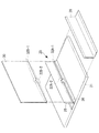
図3は、本実施形態に係るパイ型継手20の構成を示す斜視図である。 FIG. 3 is a perspective view showing the configuration of the pi-shaped joint 20 according to the present embodiment.
図3に示されるように、本実施形態に係るパイ型継手20は、溝部底面22Aの一部に、板材30と嵌め合わされる嵌合形状32A−2が形成される。本実施形態に係る嵌合形状32A−2は、一例として切欠き形状である。
As shown in FIG. 3, the pie-shaped joint 20 according to the present embodiment has a fitting shape 32 </ b> A- 2 that is fitted to the
このように、嵌合形状32A−2は、溝部底面22Aの一部に形成されているため、点で板材30の位置決めを行うものである。換言すると、嵌合形状32A−2は、溝部22の長手方向に対する板材30の位置決めの基準位置となり、溝部22の長手方向に対する板材30の位置決めを行う。
Thus, since the
一方、板材30には、嵌合形状32A−2と嵌め合わされる嵌合形状32B−2が形成される。本実施形態に係る嵌合形状32B−2は、嵌合形状32A−2と嵌め合い可能とされる突起形状である。
On the other hand, the
そして、溝部底面22Aの嵌合形状32A−1,32A−2と板材30の嵌合形状32B−1,32B−2とが嵌め合わされる。これにより、板材30Aは溝部底面22Aの嵌合形状32A−1,32A−2と合致する位置にのみ嵌め合わされる。
And
なお、図3に示される嵌合形状32A−2,32B−2は、一例として、一つであるが、これに限らず、2つ以上が例えば等間隔で形成されてもよい。さらに、嵌合形状32A−2,32B−2は、一例として、溝部22の長手方向の略中央に形成されているが、これに限らず、例えば、溝部22の端部近辺に形成されてもよい。
In addition, although the
図3の例では、L字型部材28(本体部材24)と位置決め部材26とが別構成とされているが、L字型部材28(本体部材24)と位置決め部材26とが一体成型されてもよい。なお、パイ型継20を構成するL字型部材28及び位置決め部材26の成形方法は特に限定されない。
In the example of FIG. 3, the L-shaped member 28 (main body member 24) and the positioning
以上説明したように、本実施形態に係るパイ型継手20は、母材21に設けられ、板材30が差し込まれる溝部22が形成されて、母材21と板材30とを接着により接合させるものである。そして、パイ型継手20は、溝部底面22Aの全面に、板材30と嵌め合わされる嵌合形状32A−1が形成され、溝部底面22Aの一部に、板材30と嵌め合わされる嵌合形状32A−2が形成される。
一方、板材30におけるパイ型継手20との接合面には、パイ型継手20の溝部底面22Aと嵌め合わされる嵌合形状32B−1,32B−2が形成される。
As described above, the pie-shaped joint 20 according to the present embodiment is provided in the
On the other hand, fitting shapes 32 </ b> B- 1 and 32 </ b> B- 2 that are fitted to the
従って、本実施形態に係るパイ型継手20は、溝部底面22Aの嵌合形状32A−1により、溝幅に対して所望の位置に板材30を配置できる。すなわち、溝部底面22Aの嵌合形状32A−1によって、板材30は、溝幅方向(図2,3のA方向)に対し高精度に位置決めされる。
Therefore, the pie-shaped joint 20 according to the present embodiment can arrange the
また、本実施形態に係るパイ型継手20は、溝部底面22Aの嵌合形状32A−2によって、板材30は、溝部22の長手方向(図3のB方向)に対しても高精度に位置決めされる。
Further, in the pie joint 20 according to the present embodiment, the
また、本実施形態に係るパイ型継手20に対して板材30を溝部底面22Aに向かって差し込むだけで、板材30は、溝部22の上下方向(図2,3のC方向)に対しても高精度に位置決めされる。
Further, the
また、本実施形態に係るパイ型継手20は、嵌合形状32A−1,32A−2による板材30との嵌め合わせにより、パイ型継手20に対して板材30が斜めに傾斜して接合されることも防止される。
In addition, the pie joint 20 according to the present embodiment is joined to the pie joint 20 in an inclined manner with respect to the pie joint 20 by fitting with the
さらに、パイ型継手20には予め嵌合形状32A−1,32A−2が形成され、板材30には予め嵌合形状32B−1,32B−2が形成されている。このため、パイ型継手20に板材30を差し込むだけで、位置決めができるので、例えば位置決めピンを用いるような従来の方法に比べて、構造組み立ての工程を簡略化でき、組み立てに要する時間を短縮できる。
Furthermore,
〔第1変形例〕
以下、本発明の第1変形例について説明する。
[First Modification]
Hereinafter, a first modification of the present invention will be described.
図4は、本発明の第1変形例に係るパイ型継手20の側面図である。なお、図4における図2と同一の構成部分については図2と同一の符号を付して、その説明を省略する。 FIG. 4 is a side view of the pi-shaped joint 20 according to the first modification of the present invention. 4 that are the same as in FIG. 2 are assigned the same reference numerals as in FIG. 2, and descriptions thereof are omitted.
本第1変形例に係る溝部底面22Aの嵌合形状32A−1は、溝幅の中心線CLを軸に左右非対称な形状とされる。
The
図4に示されるように、本第1変形例では、嵌合形状32A−1は、略中心に凸型の円弧形状(R形状)が形成され、その左右では高さの異なる平坦形状が形成される。
一方、板材30には、嵌合形状32A−1と嵌め合わされる嵌合形状32B−1として、凹型の円弧形状とその左右に高さの異なる平坦形状が形成される。
As shown in FIG. 4, in the first modification, the
On the other hand, the
〔第2変形例〕
以下、本発明の第2変形例について説明する。
[Second Modification]
Hereinafter, a second modification of the present invention will be described.
図5は、本発明の第2変形例に係るパイ型継手20の側面図である。なお、図5における図2と同一の構成部分については図2と同一の符号を付して、その説明を省略する。 FIG. 5 is a side view of the pi-shaped joint 20 according to the second modification of the present invention. In FIG. 5, the same components as those in FIG. 2 are denoted by the same reference numerals as those in FIG.
本第2変形例に係る溝部底面22Aの嵌合形状32A−1は、溝幅の中心線CLを軸に左右非対称な形状とされる。
The
図5に示されるように、本第2変形例では、嵌合形状32A−1は、一方に斜面(テーパ形状)が形成され、他方に段差を有する平坦形状が形成される。
一方、板材30には、嵌合形状32A−1と嵌め合わされる嵌合形状32B−1として、一方に斜面が形成され、他方に段差を有する平坦形状が形成される。
As shown in FIG. 5, in the second modification, the
On the other hand, the
〔第3変形例〕
以下、本発明の第3変形例について説明する。
[Third Modification]
Hereinafter, a third modification of the present invention will be described.
図6は、本発明の第3変形例に係るパイ型継手20の斜視図である。なお、図6における図3と同一の構成部分については図3と同一の符号を付して、その説明を省略する。 FIG. 6 is a perspective view of a pi-shaped joint 20 according to a third modification of the present invention. In FIG. 6, the same components as those in FIG. 3 are denoted by the same reference numerals as those in FIG.
図6に示されるように、本第3変形例に係るパイ型継手20は、嵌合形状32A−2として、突起形状が位置決め部材26に形成される。
一方、板材30には、嵌合形状32A−2と嵌め合わされる嵌合形状32B−2として、切欠き形状が形成される。
As shown in FIG. 6, the pie-shaped joint 20 according to the third modification has a protrusion shape formed on the positioning
On the other hand, a notch shape is formed on the
以上、本発明を、上記実施形態を用いて説明したが、本発明の技術的範囲は上記実施形態に記載の範囲には限定されない。発明の要旨を逸脱しない範囲で上記実施形態に多様な変更又は改良を加えることができ、該変更又は改良を加えた形態も本発明の技術的範囲に含まれる。 As mentioned above, although this invention was demonstrated using the said embodiment, the technical scope of this invention is not limited to the range as described in the said embodiment. Various changes or improvements can be added to the above-described embodiment without departing from the gist of the invention, and embodiments to which the changes or improvements are added are also included in the technical scope of the present invention.
例えば、上記実施形態では、パイ型継手20を航空機構造に用いる形態について説明したが、本発明は、これに限定されるものではなく、パイ型継手20を航空機以外の構造に用いる形態としてもよい。 For example, in the above-described embodiment, the form in which the pie joint 20 is used for an aircraft structure has been described. However, the present invention is not limited to this, and the pie joint 20 may be used in a structure other than an aircraft. .
また、上記実施形態では、位置決め部材26に嵌合形状32A−1及び嵌合形状32A−2が形成され、板材30に嵌合形状32B−1及び嵌合形状32B−2が形成される形態について説明したが、本発明は、これに限定されるものではない。例えば、位置決め部材26に嵌合形状32A−1のみが形成され、板材30に嵌合形状32B−1のみが形成される形態としてもよい。
Moreover, in the said embodiment, about the form by which fitting shape 32A-1 and
1 主翼
20 パイ型継手
21 母材
22 溝部
24 本体部材
26 位置決め部材
30 板材
32A−1 嵌合形状
32A−2 嵌合形状
32B−1 嵌合形状
32B−2 嵌合形状
DESCRIPTION OF
Claims (7)
前記溝部の底面の全面に、前記部材と嵌め合わされる第1嵌合形状が形成され、
前記第1嵌合形状は、前記溝部の幅の中心線を軸に左右非対称な形状とされる継手。 A joint provided on a base material for forming a groove into which a member is inserted and joining the base material and the member by bonding,
A first fitting shape to be fitted to the member is formed on the entire bottom surface of the groove ,
Wherein the first fitting shape, the groove center line fitting that will be asymmetrical shape in axial width.
上面に前記嵌合形状が形成される位置決め部材と、
を備え、
前記位置決め部材は、前記上面が前記溝部の底面となるように前記本体部材に配置され、前記上面で前記部材と接合される請求項1から請求項3の何れか1項記載の継手。 A body member forming the groove,
A positioning member having the fitting shape formed on the upper surface;
With
The joint according to any one of claims 1 to 3, wherein the positioning member is disposed on the main body member so that the upper surface is a bottom surface of the groove portion, and is joined to the member on the upper surface.
前記溝部の幅方向に対する前記部材の位置決めを行うための第1嵌合形状が前記溝部の底面に形成され、
前記第1嵌合形状は、前記溝部の幅の中心線を軸に左右非対称な形状とされる継手。 A joint provided on a base material for forming a groove into which a member is inserted and joining the base material and the member by bonding,
A first fitting shape for positioning the member with respect to the width direction of the groove is formed on the bottom surface of the groove ,
Wherein the first fitting shape, the groove center line fitting that will be asymmetrical shape in axial width.
前記継手との接合面に、前記継手の前記底面と嵌め合わされる嵌合形状が形成される部材と、
を備え、
前記部材が前記継手の前記溝部に差し込まれて接着により接合される航空機構造。 A joint according to any one of claims 1 to 6,
On the joint surface with the joint, a member formed with a fitting shape to be fitted with the bottom surface of the joint;
With
An aircraft structure in which the member is inserted into the groove of the joint and joined by adhesion.
Priority Applications (8)
| Application Number | Priority Date | Filing Date | Title |
|---|---|---|---|
| JP2013207663A JP6090931B2 (en) | 2013-10-02 | 2013-10-02 | Joints and aircraft structures |
| CN201480043091.5A CN105452679B (en) | 2013-10-02 | 2014-05-20 | Connector and aviation machine structure |
| CA2919618A CA2919618C (en) | 2013-10-02 | 2014-05-20 | Joint, and aircraft structure |
| US14/908,743 US10071794B2 (en) | 2013-10-02 | 2014-05-20 | Joint, and aircraft structure |
| PCT/JP2014/063384 WO2015049895A1 (en) | 2013-10-02 | 2014-05-20 | Joint, and aircraft structure |
| BR112016002134A BR112016002134A2 (en) | 2013-10-02 | 2014-05-20 | Union and aircraft structure |
| EP14851380.7A EP3015721B1 (en) | 2013-10-02 | 2014-05-20 | Joint, and aircraft structure |
| RU2016102799A RU2636373C2 (en) | 2013-10-02 | 2014-05-20 | Aircraft junction and structure |
Applications Claiming Priority (1)
| Application Number | Priority Date | Filing Date | Title |
|---|---|---|---|
| JP2013207663A JP6090931B2 (en) | 2013-10-02 | 2013-10-02 | Joints and aircraft structures |
Publications (3)
| Publication Number | Publication Date |
|---|---|
| JP2015072042A JP2015072042A (en) | 2015-04-16 |
| JP2015072042A5 JP2015072042A5 (en) | 2016-07-07 |
| JP6090931B2 true JP6090931B2 (en) | 2017-03-08 |
Family
ID=52778492
Family Applications (1)
| Application Number | Title | Priority Date | Filing Date |
|---|---|---|---|
| JP2013207663A Active JP6090931B2 (en) | 2013-10-02 | 2013-10-02 | Joints and aircraft structures |
Country Status (8)
| Country | Link |
|---|---|
| US (1) | US10071794B2 (en) |
| EP (1) | EP3015721B1 (en) |
| JP (1) | JP6090931B2 (en) |
| CN (1) | CN105452679B (en) |
| BR (1) | BR112016002134A2 (en) |
| CA (1) | CA2919618C (en) |
| RU (1) | RU2636373C2 (en) |
| WO (1) | WO2015049895A1 (en) |
Families Citing this family (11)
| Publication number | Priority date | Publication date | Assignee | Title |
|---|---|---|---|---|
| US9199715B2 (en) * | 2013-10-10 | 2015-12-01 | The Boeing Company | Self-aligning fitting assemblies and systems and methods including the same |
| CN109641408A (en) * | 2016-06-28 | 2019-04-16 | 维斯塔斯风力系统有限公司 | The manufacturing method of wind turbine blade |
| US10696373B2 (en) * | 2016-09-13 | 2020-06-30 | The Boeing Company | Aircraft wings and aircraft including such aircraft wings |
| US10703419B2 (en) * | 2017-05-19 | 2020-07-07 | Divergent Technologies, Inc. | Apparatus and methods for joining panels |
| US10605631B2 (en) * | 2017-08-03 | 2020-03-31 | Sikorsky Aircraft Corporation | Structural pi joint with integrated fiber optic sensing |
| US11091266B2 (en) | 2017-08-29 | 2021-08-17 | Goodrich Corporation | Conformable tank fabricated using additive manufacturing |
| US11939105B2 (en) * | 2017-08-29 | 2024-03-26 | Goodrich Corporation | 3D woven conformable tank |
| US10703481B2 (en) | 2017-08-29 | 2020-07-07 | Goodrich Corporation | Conformable tank with sandwich structure walls |
| US10816138B2 (en) | 2017-09-15 | 2020-10-27 | Goodrich Corporation | Manufacture of a conformable pressure vessel |
| CN109236819B (en) * | 2018-09-19 | 2023-11-24 | 苏州富强科技有限公司 | Device for positioning and maintaining pressure of L-shaped part |
| EP3954907A4 (en) * | 2019-04-12 | 2022-04-13 | IHI Aerospace Co., Ltd. | Joint structure and assembly method for same |
Family Cites Families (29)
| Publication number | Priority date | Publication date | Assignee | Title |
|---|---|---|---|---|
| US4671470A (en) * | 1985-07-15 | 1987-06-09 | Beech Aircraft Corporation | Method for fastening aircraft frame elements to sandwich skin panels covering same using woven fiber connectors |
| US5474635A (en) * | 1994-03-07 | 1995-12-12 | United Technologies Corporation | Joining non-coplanar panels and structures of fiber reinforced composites |
| JP3667200B2 (en) * | 2000-07-12 | 2005-07-06 | 株式会社イシモク・コーポレーション | Connection structure of wood products |
| US6374570B1 (en) * | 2000-08-25 | 2002-04-23 | Lockheed Martin Corporation | Apparatus and method for joining dissimilar materials to form a structural support member |
| US6849150B1 (en) * | 2001-01-16 | 2005-02-01 | Lockheed Martin Corporation | System and method of forming structural assemblies with 3-D woven joint pre-forms |
| US6863767B2 (en) * | 2001-08-23 | 2005-03-08 | Lockheed Martin Corporation | Paste-bond clevis joint |
| US7205066B1 (en) * | 2002-05-23 | 2007-04-17 | Rohr, Inc. | Structural element with rib-receiving member |
| US6749155B2 (en) | 2002-09-13 | 2004-06-15 | The Boeing Company | Composite assembly with integrated composite joints |
| JP3659249B2 (en) * | 2002-12-27 | 2005-06-15 | 住友金属工業株式会社 | Steel sheet pile and sheet pile steel wall |
| JP2004216672A (en) * | 2003-01-14 | 2004-08-05 | Pearl Mannequin:Kk | Hollow united molded object and mold |
| US7037568B1 (en) * | 2003-07-15 | 2006-05-02 | Rogers Terry W | Joining member for mechanically joining a skin to a supporting rib |
| US7555873B2 (en) | 2004-11-30 | 2009-07-07 | The Boeing Company | Self-locating feature for a pi-joint assembly |
| US8272618B2 (en) | 2004-11-30 | 2012-09-25 | The Boeing Company | Minimum bond thickness assembly feature assurance |
| US20060115320A1 (en) * | 2004-11-30 | 2006-06-01 | The Boeing Company | Determinant assembly features for vehicle structures |
| US7393488B2 (en) * | 2005-05-25 | 2008-07-01 | The Boeing Company | Methods of joining structures and joints formed thereby |
| US7670527B2 (en) * | 2006-05-09 | 2010-03-02 | Lockheed Martin Corporation | Failsafe injected adhesive joint |
| US8082667B2 (en) * | 2007-05-31 | 2011-12-27 | The Boeing Company | Apparatus and methods for securing a first structural member and a second structural member to one another |
| WO2010063413A1 (en) | 2008-12-04 | 2010-06-10 | Bayer Materialscience Ag | Glued composite plastic part, method for the production thereof, and part made therefrom |
| DE102009023708A1 (en) | 2009-06-03 | 2010-12-16 | Kgt Graphit Technologie Gmbh | Positive and non-positive connection of special graphite parts to multi-part graphite components |
| FR2954200B1 (en) | 2009-12-23 | 2012-03-02 | Snecma | PROCESS FOR MAKING A TURBOMACHINE METAL TURBINE REINFORCEMENT |
| CN102473881A (en) * | 2010-02-02 | 2012-05-23 | 松下电器产业株式会社 | Battery case and battery pack provided therewith |
| US9073267B1 (en) * | 2010-03-10 | 2015-07-07 | The Boeing Company | Method of assembling panels and adhesively bonded joints used therein |
| RU103588U1 (en) * | 2010-08-20 | 2011-04-20 | Владимир Владимирович Жебелев | GLUE BOTTOM TRANSMISSION |
| DE102010064060A1 (en) | 2010-12-23 | 2012-06-28 | Airbus Operations Gmbh | Fastening arrangement for fastening a component of an aircraft or spacecraft, adhesive container of such a fastening arrangement and aircraft or spacecraft with such a fastening arrangement and / or such a Klebehalter |
| CN103261021B (en) * | 2010-12-28 | 2016-01-20 | 贝尔直升机泰克斯特龙公司 | Multidirectional load connected system |
| CN202244075U (en) * | 2011-06-03 | 2012-05-30 | 哈尔滨飞机工业集团有限责任公司 | Frame and wallboard connecting structure |
| US8393871B2 (en) * | 2011-07-19 | 2013-03-12 | General Electric Company | Wind turbine blade shear web connection assembly |
| US9017510B2 (en) * | 2011-12-13 | 2015-04-28 | The Boeing Company | Method and apparatus for fabricating large scale integrated airfoils |
| US9681527B2 (en) * | 2013-03-29 | 2017-06-13 | The Boeing Company | Method and apparatus for providing a current return network in an aircraft structure |
-
2013
- 2013-10-02 JP JP2013207663A patent/JP6090931B2/en active Active
-
2014
- 2014-05-20 US US14/908,743 patent/US10071794B2/en active Active
- 2014-05-20 EP EP14851380.7A patent/EP3015721B1/en active Active
- 2014-05-20 RU RU2016102799A patent/RU2636373C2/en active
- 2014-05-20 CN CN201480043091.5A patent/CN105452679B/en not_active Expired - Fee Related
- 2014-05-20 BR BR112016002134A patent/BR112016002134A2/en active Search and Examination
- 2014-05-20 CA CA2919618A patent/CA2919618C/en not_active Expired - Fee Related
- 2014-05-20 WO PCT/JP2014/063384 patent/WO2015049895A1/en active Application Filing
Also Published As
| Publication number | Publication date |
|---|---|
| EP3015721A1 (en) | 2016-05-04 |
| RU2636373C2 (en) | 2017-11-22 |
| JP2015072042A (en) | 2015-04-16 |
| EP3015721B1 (en) | 2021-07-14 |
| US10071794B2 (en) | 2018-09-11 |
| WO2015049895A1 (en) | 2015-04-09 |
| CA2919618A1 (en) | 2015-04-09 |
| BR112016002134A2 (en) | 2017-08-01 |
| US20160244140A1 (en) | 2016-08-25 |
| EP3015721A4 (en) | 2016-07-13 |
| CN105452679A (en) | 2016-03-30 |
| CN105452679B (en) | 2019-01-04 |
| CA2919618C (en) | 2019-09-24 |
| RU2016102799A (en) | 2017-11-10 |
Similar Documents
| Publication | Publication Date | Title |
|---|---|---|
| JP6090931B2 (en) | Joints and aircraft structures | |
| US9193433B2 (en) | Double-sided stiffened composite panel and method for producing such a panel | |
| US10648451B2 (en) | Method for manufacturing a rotor blade of a wind power plant, rotor blade and wind power plant | |
| EP2822852B1 (en) | Bonded splice joint | |
| JP6169465B2 (en) | Joints and aircraft structures | |
| JP2009519861A5 (en) | ||
| BR112016029061B1 (en) | TIP SYSTEM FOR A WIND TURBINE BLADE | |
| US10451030B2 (en) | Wind turbine blade and a method of assembling a wind turbine blade and a spar cap connection piece | |
| JP6255172B2 (en) | Composite structural panels and aircraft fuselage | |
| US8679616B2 (en) | Skew-angle radius filler | |
| EP3098440B1 (en) | A wind turbine blade and a method of assembling a wind turbine blade and a spar cap connection piece | |
| US20150183503A1 (en) | Stiffener element and manufacturing method thereof | |
| US9623955B2 (en) | Composite reinforcement component, structural element, aircraft or spacecraft and method for producing a composite reinforcement component | |
| US8002651B2 (en) | Tennis racquet frame, its method of manufacture, and racquet comprising such a frame | |
| JP2019157975A (en) | Double skin structure and method for manufacturing the same | |
| JP2014015002A (en) | Corner joint component | |
| US20100052285A1 (en) | Integral Bicycle Frame | |
| WO2013078647A1 (en) | Panel,component for an airplane airfoil comprising the panel,and method for producing the panel | |
| KR20130039468A (en) | Blade for wind turbine and method for manufacturing the same | |
| JP2019167063A (en) | Vehicle wheel | |
| JP2014004728A (en) | Frp-made panel member | |
| CN108032988B (en) | Fiber reinforced composite aircraft cabin connecting structure and preparation method thereof | |
| JP6025246B2 (en) | Wing ribs | |
| JP2010228635A (en) | Instrument panel | |
| KR20130092159A (en) | Blade for wind turbine and method for manufacturing the same |
Legal Events
| Date | Code | Title | Description |
|---|---|---|---|
| A621 | Written request for application examination |
Free format text: JAPANESE INTERMEDIATE CODE: A621 Effective date: 20160518 |
|
| A521 | Request for written amendment filed |
Free format text: JAPANESE INTERMEDIATE CODE: A523 Effective date: 20160520 |
|
| TRDD | Decision of grant or rejection written | ||
| A01 | Written decision to grant a patent or to grant a registration (utility model) |
Free format text: JAPANESE INTERMEDIATE CODE: A01 Effective date: 20170110 |
|
| A61 | First payment of annual fees (during grant procedure) |
Free format text: JAPANESE INTERMEDIATE CODE: A61 Effective date: 20170203 |
|
| R150 | Certificate of patent or registration of utility model |
Ref document number: 6090931 Country of ref document: JP Free format text: JAPANESE INTERMEDIATE CODE: R150 |