EP3450057A1 - Procédé de débouchage de canalisations dans des pièces obtenues par fabrication additive - Google Patents
Procédé de débouchage de canalisations dans des pièces obtenues par fabrication additive Download PDFInfo
- Publication number
- EP3450057A1 EP3450057A1 EP18186414.1A EP18186414A EP3450057A1 EP 3450057 A1 EP3450057 A1 EP 3450057A1 EP 18186414 A EP18186414 A EP 18186414A EP 3450057 A1 EP3450057 A1 EP 3450057A1
- Authority
- EP
- European Patent Office
- Prior art keywords
- guide
- pipes
- well
- additive manufacturing
- channels
- Prior art date
- Legal status (The legal status is an assumption and is not a legal conclusion. Google has not performed a legal analysis and makes no representation as to the accuracy of the status listed.)
- Granted
Links
Images

Classifications
-
- B—PERFORMING OPERATIONS; TRANSPORTING
- B08—CLEANING
- B08B—CLEANING IN GENERAL; PREVENTION OF FOULING IN GENERAL
- B08B9/00—Cleaning hollow articles by methods or apparatus specially adapted thereto
-
- B—PERFORMING OPERATIONS; TRANSPORTING
- B22—CASTING; POWDER METALLURGY
- B22F—WORKING METALLIC POWDER; MANUFACTURE OF ARTICLES FROM METALLIC POWDER; MAKING METALLIC POWDER; APPARATUS OR DEVICES SPECIALLY ADAPTED FOR METALLIC POWDER
- B22F10/00—Additive manufacturing of workpieces or articles from metallic powder
- B22F10/60—Treatment of workpieces or articles after build-up
- B22F10/68—Cleaning or washing
-
- B—PERFORMING OPERATIONS; TRANSPORTING
- B22—CASTING; POWDER METALLURGY
- B22F—WORKING METALLIC POWDER; MANUFACTURE OF ARTICLES FROM METALLIC POWDER; MAKING METALLIC POWDER; APPARATUS OR DEVICES SPECIALLY ADAPTED FOR METALLIC POWDER
- B22F3/00—Manufacture of workpieces or articles from metallic powder characterised by the manner of compacting or sintering; Apparatus specially adapted therefor ; Presses and furnaces
- B22F3/24—After-treatment of workpieces or articles
-
- B—PERFORMING OPERATIONS; TRANSPORTING
- B22—CASTING; POWDER METALLURGY
- B22F—WORKING METALLIC POWDER; MANUFACTURE OF ARTICLES FROM METALLIC POWDER; MAKING METALLIC POWDER; APPARATUS OR DEVICES SPECIALLY ADAPTED FOR METALLIC POWDER
- B22F5/00—Manufacture of workpieces or articles from metallic powder characterised by the special shape of the product
- B22F5/009—Manufacture of workpieces or articles from metallic powder characterised by the special shape of the product of turbine components other than turbine blades
-
- B—PERFORMING OPERATIONS; TRANSPORTING
- B22—CASTING; POWDER METALLURGY
- B22F—WORKING METALLIC POWDER; MANUFACTURE OF ARTICLES FROM METALLIC POWDER; MAKING METALLIC POWDER; APPARATUS OR DEVICES SPECIALLY ADAPTED FOR METALLIC POWDER
- B22F5/00—Manufacture of workpieces or articles from metallic powder characterised by the special shape of the product
- B22F5/10—Manufacture of workpieces or articles from metallic powder characterised by the special shape of the product of articles with cavities or holes, not otherwise provided for in the preceding subgroups
- B22F5/106—Tube or ring forms
-
- B—PERFORMING OPERATIONS; TRANSPORTING
- B29—WORKING OF PLASTICS; WORKING OF SUBSTANCES IN A PLASTIC STATE IN GENERAL
- B29C—SHAPING OR JOINING OF PLASTICS; SHAPING OF MATERIAL IN A PLASTIC STATE, NOT OTHERWISE PROVIDED FOR; AFTER-TREATMENT OF THE SHAPED PRODUCTS, e.g. REPAIRING
- B29C64/00—Additive manufacturing, i.e. manufacturing of three-dimensional [3D] objects by additive deposition, additive agglomeration or additive layering, e.g. by 3D printing, stereolithography or selective laser sintering
- B29C64/30—Auxiliary operations or equipment
- B29C64/35—Cleaning
-
- B—PERFORMING OPERATIONS; TRANSPORTING
- B33—ADDITIVE MANUFACTURING TECHNOLOGY
- B33Y—ADDITIVE MANUFACTURING, i.e. MANUFACTURING OF THREE-DIMENSIONAL [3D] OBJECTS BY ADDITIVE DEPOSITION, ADDITIVE AGGLOMERATION OR ADDITIVE LAYERING, e.g. BY 3D PRINTING, STEREOLITHOGRAPHY OR SELECTIVE LASER SINTERING
- B33Y40/00—Auxiliary operations or equipment, e.g. for material handling
- B33Y40/20—Post-treatment, e.g. curing, coating or polishing
-
- B—PERFORMING OPERATIONS; TRANSPORTING
- B08—CLEANING
- B08B—CLEANING IN GENERAL; PREVENTION OF FOULING IN GENERAL
- B08B1/00—Cleaning by methods involving the use of tools
- B08B1/10—Cleaning by methods involving the use of tools characterised by the type of cleaning tool
- B08B1/16—Rigid blades, e.g. scrapers; Flexible blades, e.g. wipers
- B08B1/165—Scrapers
-
- B—PERFORMING OPERATIONS; TRANSPORTING
- B08—CLEANING
- B08B—CLEANING IN GENERAL; PREVENTION OF FOULING IN GENERAL
- B08B9/00—Cleaning hollow articles by methods or apparatus specially adapted thereto
- B08B9/02—Cleaning pipes or tubes or systems of pipes or tubes
- B08B9/027—Cleaning the internal surfaces; Removal of blockages
- B08B9/04—Cleaning the internal surfaces; Removal of blockages using cleaning devices introduced into and moved along the pipes
- B08B9/043—Cleaning the internal surfaces; Removal of blockages using cleaning devices introduced into and moved along the pipes moved by externally powered mechanical linkage, e.g. pushed or drawn through the pipes
- B08B9/0436—Cleaning the internal surfaces; Removal of blockages using cleaning devices introduced into and moved along the pipes moved by externally powered mechanical linkage, e.g. pushed or drawn through the pipes provided with mechanical cleaning tools, e.g. scrapers, with or without additional fluid jets
-
- B—PERFORMING OPERATIONS; TRANSPORTING
- B22—CASTING; POWDER METALLURGY
- B22F—WORKING METALLIC POWDER; MANUFACTURE OF ARTICLES FROM METALLIC POWDER; MAKING METALLIC POWDER; APPARATUS OR DEVICES SPECIALLY ADAPTED FOR METALLIC POWDER
- B22F10/00—Additive manufacturing of workpieces or articles from metallic powder
- B22F10/20—Direct sintering or melting
- B22F10/28—Powder bed fusion, e.g. selective laser melting [SLM] or electron beam melting [EBM]
-
- B—PERFORMING OPERATIONS; TRANSPORTING
- B22—CASTING; POWDER METALLURGY
- B22F—WORKING METALLIC POWDER; MANUFACTURE OF ARTICLES FROM METALLIC POWDER; MAKING METALLIC POWDER; APPARATUS OR DEVICES SPECIALLY ADAPTED FOR METALLIC POWDER
- B22F10/00—Additive manufacturing of workpieces or articles from metallic powder
- B22F10/70—Recycling
- B22F10/73—Recycling of powder
-
- B—PERFORMING OPERATIONS; TRANSPORTING
- B22—CASTING; POWDER METALLURGY
- B22F—WORKING METALLIC POWDER; MANUFACTURE OF ARTICLES FROM METALLIC POWDER; MAKING METALLIC POWDER; APPARATUS OR DEVICES SPECIALLY ADAPTED FOR METALLIC POWDER
- B22F3/00—Manufacture of workpieces or articles from metallic powder characterised by the manner of compacting or sintering; Apparatus specially adapted therefor ; Presses and furnaces
- B22F3/24—After-treatment of workpieces or articles
- B22F2003/247—Removing material: carving, cleaning, grinding, hobbing, honing, lapping, polishing, milling, shaving, skiving, turning the surface
-
- B—PERFORMING OPERATIONS; TRANSPORTING
- B22—CASTING; POWDER METALLURGY
- B22F—WORKING METALLIC POWDER; MANUFACTURE OF ARTICLES FROM METALLIC POWDER; MAKING METALLIC POWDER; APPARATUS OR DEVICES SPECIALLY ADAPTED FOR METALLIC POWDER
- B22F2999/00—Aspects linked to processes or compositions used in powder metallurgy
-
- B—PERFORMING OPERATIONS; TRANSPORTING
- B33—ADDITIVE MANUFACTURING TECHNOLOGY
- B33Y—ADDITIVE MANUFACTURING, i.e. MANUFACTURING OF THREE-DIMENSIONAL [3D] OBJECTS BY ADDITIVE DEPOSITION, ADDITIVE AGGLOMERATION OR ADDITIVE LAYERING, e.g. BY 3D PRINTING, STEREOLITHOGRAPHY OR SELECTIVE LASER SINTERING
- B33Y10/00—Processes of additive manufacturing
-
- Y—GENERAL TAGGING OF NEW TECHNOLOGICAL DEVELOPMENTS; GENERAL TAGGING OF CROSS-SECTIONAL TECHNOLOGIES SPANNING OVER SEVERAL SECTIONS OF THE IPC; TECHNICAL SUBJECTS COVERED BY FORMER USPC CROSS-REFERENCE ART COLLECTIONS [XRACs] AND DIGESTS
- Y02—TECHNOLOGIES OR APPLICATIONS FOR MITIGATION OR ADAPTATION AGAINST CLIMATE CHANGE
- Y02P—CLIMATE CHANGE MITIGATION TECHNOLOGIES IN THE PRODUCTION OR PROCESSING OF GOODS
- Y02P10/00—Technologies related to metal processing
- Y02P10/25—Process efficiency
Definitions
- the invention relates to a method of uncoupling pipes in parts obtained by additive manufacturing.
- Particles of titanium alloy in the form of powder are introduced in successive layers in a vacuum chamber.
- the enclosure is heated, typically at a temperature of the order of 700 degrees.
- the introduced layer is first preheated to solidify as an amalgam of sintered particles.
- an electron gun is commanded to bombard the portion of the amalgamated layer intended to form the part being manufactured and cause it to melt.
- This cleaning operation is usually done in closed chamber to recover the particles, for example using a compressed air nozzle.
- a compressed air nozzle typically a few millimeters
- the aim of the invention is to propose a process for unclogging coin orifices made by additive manufacturing and starting from through wells.
- the inventors have experimented with various cleaning processes. It turns out that a simple flexible wire rope, carried by a mandrel of a percussion tool and introduced into a pipe can open in it a passage opening so that the nozzle can be used effectively to completely clean. the pipeline.
- the use of a guide according to the invention makes it possible to make sure to penetrate the cable into the pipe from the well.
- the guide may be manufactured additively, preferably in the same material as the block to not introduce pollution during the operation, and of course, reused for different parts.
- the cleaning operation is preferably carried out inside the closed enclosure to allow the recovery of powder.
- the figure 1 represents a piece 1 of titanium alloy obtained by additive manufacturing by the electron beam melting process.
- This part 1 is a hydraulic block which comprises two wells 2,3 (typically of a diameter of a few centimeters) intended to receive distribution drawers, as well as a plurality of fine channels (typically of a diameter of a few millimeters) some of which, such as 4,5,6 pipelines, open out into ports, and others such as Line 7 extend between wells 2,3.
- the figure shows the part 1 completely cleaned, but it is necessary to imagine that the piece leaves the additive manufacturing machine surrounded and filled with an amalgam of metal particles weakly joined together that should be eliminated.
- the outside of the room 1 and the inside of the wells 2, 3 is easy to clean using, for example, a compressed air nozzle.
- the inside of the vent pipes 4,5,6 can be cleaned using a cable gradually pushed into the pipes by their outward outlet.
- the cable may for example be held by the mandrel of a percussion drill or any other portable power tool so that the cable rotates and causes percussion on the amalgamated powder inside the pipes and gradually releases into the pipe a passage that eventually fully open the pipe. It is then sufficient to finish the cleaning of the pipe with the help of the air nozzle to rid it completely of the amalgamated particles.
- the invention is more particularly concerned with uncoupling pipes such as pipe 7 (also visible in FIG. figure 3 ) that are difficult to access for a cleaning cable.
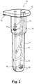
- a guide 10 illustrated in FIG. figure 2 which comprises a body 11 intended to be inserted into one of the wells 2,3 and which comprises a base 12 which remains external to the well 2,3 and which carries a finger 13 intended to be received in a cavity ad-hoc arranged on the piece 1 for indexing the guide 10 in the well.
- the guide 10 here made of plastic and obtained by additive manufacturing, comprises channels 14 which open on the one hand on the base 12 and on the other hand on the outer wall of the body 11 opposite one of the internal pipes of the room 1.
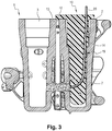
- the guide 10 has been put in place in the well 2. It is seen the introduction of a cable 20 into one of the channels 14 which guides this cable to the inlet of the internal pipe 7 of the piece 1 filled with amalgamated particles.
- the cable 20 can then be introduced into said pipe to open gradually by being rotated and struck by a hammer drill or any similar portable tool.
- the cable 20 is removed and it is engaged in another of the channels 14 of the guide 10 to open another internal pipe of the part 1.
- the guide 10 is removed and the cleaning of the pipes is completed using the nozzle to rid them completely of the amalgamated powder.
- the body 11 has a diameter slightly smaller than that of the well in which it is introduced so as to provide a space 15 between the guide 10 and the wall of the well 2 adapted to receive the metal powder unhooked by the cable during its introduction into the ducts of the room 1.
- the body 11 comprises studs 16 which cooperate with the wall of the well 2 to ensure the fit introduction and positioning of the guide 10 in the well 2.
- Two separate guides 10 can be made to enter each of the wells 2,3 in the room. Alternatively, if the two wells have the same diameter and depth, we can make a single guide that will include all the channels needed to reach all the pipes leading into one or the other of the wells.
- a wire rope is used as an unclogging tool, it will more generally be possible to use any fine and flexible tool adapted to penetrate the pipes to dig a channel in the amalgamated powder. This tool will be able to print any movement (rotation, percussion, vibrations ...) to facilitate the digging of the canal.
Landscapes
- Engineering & Computer Science (AREA)
- Mechanical Engineering (AREA)
- Manufacturing & Machinery (AREA)
- Chemical & Material Sciences (AREA)
- Materials Engineering (AREA)
- Physics & Mathematics (AREA)
- Optics & Photonics (AREA)
- Cleaning In General (AREA)
- Powder Metallurgy (AREA)
Abstract
- fabriquer un guide (10) avec un corps (11) destiné à être introduit dans le puits à ajustement, le guide comportant des canaux internes (14) qui s'étendent depuis une base (12) du guide accessible par l'utilisateur jusqu'à une paroi externe du corps ;
- nettoyer le puits et introduire le corps du guide dans le puits de sorte que les canaux du guide débouchent en regard des entrées des canalisations (7) à déboucher ;
- introduire par la base du guide dans au moins canal de celui-ci un outil fin et flexible (20), par exemple un câble métallique, et le faire pénétrer dans la canalisation de la pièce en regard jusqu'à la déboucher.
Description
- L'invention concerne un procédé de débouchage de canalisations dans des pièces obtenues par fabrication additive.
- En aéronautique, l'intérêt s'est récemment porté sur la réalisation de blocs hydrauliques en titane par la technologie de fabrication additive, notamment la fusion par faisceau d'électrons.
- Des particules d'alliage de titane (typiquement du TA6A14V) sous forme de poudre sont introduites par couches successives dans une enceinte sous vide. L'enceinte est chauffée, typiquement à une température de l'ordre de 700 degrés. La couche introduite est d'abord préchauffée pour qu'elle se solidarise sous la forme d'un amalgame de particules frittées. Puis un canon à électron est commandé pour bombarder la partie de la couche amalgamée destinée à former la pièce en cours de fabrication et provoquer sa fusion. On obtient ainsi une pièce en alliage solide, de caractéristiques mécaniques se situant entre une pièce moulée et une pièce forgée, mais dont tous les espaces libres, et notamment les canalisations et autres orifices, sont remplis de cet amalgame de particules de métal faiblement liées entre elles. Après refroidissement de la pièce, il convient donc d'éliminer complètement cet amalgame.
- Cette opération de nettoyage se fait généralement en enceinte close pour récupérer les particules, à l'aide par exemple d'une buse à air comprimé. Cependant, l'expérience montre que les canalisations de faible diamètre (typiquement quelques millimètres) que l'on trouve habituellement dans les blocs hydrauliques sont impossibles à nettoyer à l'aide d'une buse.
- Il a été proposé dans le document
EP3153256 de fabriquer un cordon de métal solidifié à l'intérieur de chacune des canalisations en même temps que le reste de la pièce. Lors du nettoyage de la pièce, on commence par extraire le cordon de chacune des canalisations, qui entraîne avec lui une bonne partie des particules amalgamées présente dans l'orifice. Celui-ci est alors débouché et il suffit de finir le nettoyage avec la buse. Cependant, ce procédé n'est pas adapté à toutes les canalisations. Certaines d'entre elles ont une conformation tortueuse qui empêche l'extraction du cordon. En outre, la rupture d'un cordon en cours d'extraction est catastrophique puisqu'il sera impossible d'extraire la partie du cordon encore présente dans la canalisation. Enfin, le cordon ainsi constitué représente de la matière fusionnée et irrécupérable, augmentant le temps et le coût de fabrication de la pièce. - Dans le cas particulier des blocs hydrauliques, certaines des canalisations de petit diamètre partent non de la surface de la pièce, mais de l'intérieur de puits débouchants de grand diamètre destinés à recevoir des tiroirs de distribution. Leur accès est particulièrement difficile.
- L'invention vise à proposer un procédé de débouchage d'orifices de pièces réalisées par fabrication additive et partant de puits débouchants.
- En vue de la réalisation de ce but, on propose un procédé de débouchage de canalisations d'une pièce réalisée par fabrication additive, les canalisations partant d'au moins un puits débouchant à la surface de la pièce, le procédé comportant les étapes de :
- fabriquer un guide avec un corps destiné à être introduit dans le puits à ajustement, le guide comportant des canaux internes qui s'étendent depuis une base du guide accessible par l'utilisateur jusqu'à une paroi externe du corps ;
- nettoyer le puits et introduire le corps du guide dans le puits de sorte que les canaux du guide débouchent en regard des entrées des canalisations de la pièce à déboucher ;
- introduire par la base du guide dans au moins un canal ce celui-ci un outil fin et flexible, par exemple un câble métallique, et le faire pénétrer dans la canalisation de la pièce en regard jusqu'à la déboucher.
- Les inventeurs ont expérimenté divers procédés de nettoyage. Il s'avère qu'un simple câble métallique flexible, porté par un mandrin d'un outil à percussion et introduit dans une canalisation permet d'ouvrir dans celle-ci un passage débouchant de sorte que la buse puisse être utilisée efficacement pour nettoyer complètement la canalisation. L'utilisation d'un guide selon l'invention permet de faire pénétrer à coup sûr le câble dans la canalisation depuis le puits.
- Le guide pourra être fabriqué de façon additive, de préférence dans la même matière que le bloc pour ne pas introduire de pollution lors de l'opération, et bien entendu, réutilisé pour différentes pièces.
- L'opération de nettoyage se fait de préférence à l'intérieur de l'enceinte close pour permettre la récupération de poudre.
- L'invention sera mieux comprise à la lumière de la description détaillée qui suit d'un mode particulier de mise en oeuvre en référence aux figures des dessins annexés parmi lesquelles :
- la
figure 1 est une vue en perspective d'une pièce en alliage de titane obtenue par fabrication additive comportant deux puits desquels partent une série d'orifices à déboucher ; - la
figure 2 est une vue en perspective d'un guide selon l'invention adaptée à la pièce de lafigure 1 , illustré en transparence pour que les canaux internes soient visibles ; - La
figure 3 est une vue en coupe de la pièce munie du guide, montrant l'un des canaux du guide débouchant en regard de l'entrée d'une des canalisations de la pièce. - La
figure 1 représente une pièce 1 en alliage de titane obtenue par fabrication additive par le procédé de fusion par faisceau d'électrons. Cette pièce 1 est un bloc hydraulique qui comporte deux puits 2,3 (typiquement d'un diamètre de quelques centimètres) destinés à recevoir des tiroirs de distribution, ainsi qu'une pluralité de canalisations fines (typiquement d'un diamètre de quelques millimètres), dont certaines comme les canalisations 4,5,6 débouchent sur l'extérieur par des ports, et d'autres comme la canalisation 7 s'étendent entre les puits 2,3. - La figure représente la pièce 1 entièrement nettoyée, mais il faut s'imaginer que la pièce sort de la machine de fabrication additive entourée et remplie d'un amalgame de particules de métal faiblement solidarisées entre elles qu'il convient d'éliminer. L'extérieur de la pièce 1 ainsi que l'intérieur des puits 2,3 est facile à nettoyer à l'aide par exemple d'une buse à air comprimé. L'intérieur des canalisations débouchantes 4,5,6 peut être nettoyé à l'aide d'un câble enfoncé progressivement dans les canalisations par leur débouché extérieur. Le câble pourra par exemple être tenu par le mandrin d'une perceuse à percussion ou tout autre outil motorisé portatif de sorte que le câble tourne et provoque des percussions sur la poudre amalgamée à l'intérieur des canalisations et dégage progressivement dans la canalisation un passage qui finit par déboucher entièrement la canalisation. Il suffit alors de finir le nettoyage de la canalisation à l'aide de la buse à air comprimé pour la débarrasser entièrement des particules amalgamées.
- L'invention s'intéresse plus particulièrement au débouchage des canalisations telles que la canalisation 7 (également visible à la
figure 3 ) qui sont difficiles d'accès pour un câble de nettoyage. Selon l'invention, on prévoit l'utilisation d'un guide 10 illustré à lafigure 2 , qui comporte un corps 11 destiné à être inséré dans l'un des puits 2,3 et qui comporte une base 12 qui reste extérieure au puits 2,3 et qui porte un doigt 13 destiné à être reçu dans une cavité ad-hoc ménagée sur la pièce 1 pour l'indexage du guide 10 dans le puits. Le guide 10, ici en matière plastique et obtenu par fabrication additive, comporte des canaux 14 qui débouchent d'une part sur la base 12 et d'autre part sur la paroi externe du corps 11 en regard d'une des canalisations internes de la pièce 1. - A la
figure 3 , le guide 10 a été mis en place dans le puits 2. On voit l'introduction d'un câble 20 dans l'un des canaux 14 qui guide ce câble jusqu'à l'entrée de la canalisation interne 7 de la pièce 1 remplie de particules amalgamées. Le câble 20 peut alors être introduit dans ladite canalisation pour la déboucher progressivement en étant mis en rotation et percuté par une perceuse à percussion ou tout autre outil portatif similaire. Une fois la canalisation débouchée, on retire le câble 20 et on l'engage dans un autre des canaux 14 du guide 10 pour déboucher une autre canalisation interne de la pièce 1. Quand toutes les canalisations sont débouchées, on retire le guide 10 et on finit le nettoyage des canalisations à l'aide de la buse pour les débarrasser entièrement de la poudre amalgamée. - Le corps 11 a un diamètre légèrement inférieur à celui du puits dans lequel il est introduit de façon à ménager un espace 15 entre le guide 10 et la paroi du puits 2 adapté à recevoir la poudre métallique décrochée par le câble lors de son introduction dans les canalisations de la pièce 1. Pour centrer le guide 10 dans le puits 2, le corps 11 comporte des plots 16 qui coopèrent avec la paroi du puits 2 pour assurer l'introduction à ajustement et le positionnement du guide 10 dans le puits 2.
- On peut fabriquer deux guides 10 distincts pour pénétrer dans chacun des puits 2,3 de la pièce. Alternativement, si les deux puits ont un diamètre et une profondeur identiques, on peut fabriquer un unique guide qui comportera tous les canaux nécessaires pour atteindre toutes les canalisations débouchant dans l'un ou l'autre des puits.
- L'invention n'est pas limitée à ce qui vient d'être décrit mais englobe au contraire toute variante entrant dans le cadre défini par les revendications.
- En particulier, bien que dans l'exemple illustré, on utilise un câble métallique en guise d'outil de débouchage, on pourra plus généralement utiliser tout outil fin et flexible adapté à pénétrer dans les canalisations pour y creuser un canal dans la poudre amalgamée. On pourra imprimer à cet outil tout mouvement (rotation, percussions, vibrations...) propre à faciliter le creusement du canal.
Claims (5)
- Procédé de débouchage de canalisations (7) d'une pièce (1) réalisée par fabrication additive, les canalisations partant d'au moins un puits (2,3) débouchant à la surface de la pièce, le procédé comportant les étapes de :- fabriquer un guide (10) avec un corps (11) destiné à être introduit dans le puits à ajustement, le guide comportant des canaux internes (14) qui s'étendent depuis une base (12) du guide accessible par l'utilisateur jusqu'à une paroi externe du corps ;- nettoyer le puits et introduire le corps du guide dans le puits de sorte que les canaux du guide débouchent en regard des entrées des canalisations (7) à déboucher ;- introduire par la base du guide dans au moins un canal de celui-ci un outil fin et flexible (20), par exemple un câble métallique, et le faire pénétrer dans la canalisation de la pièce en regard jusqu'à la déboucher.
- Procédé selon la revendication 1, dans lequel on imprime à l'outil flexible au moins un mouvement de rotation, de vibration, ou de percussion.
- Procédé selon la revendication 1, dans lequel on utilise le même guide (10) pour déboucher des canalisations partant de deux puits distincts, le guide comportant tous les canaux propres à déboucher en regard de toutes les canalisations des deux puits.
- Procédé selon la revendication 1, dans lequel le guide (10) est fabriqué en matière plastique ou en résine à l'aide d'un procédé de fabrication additive.
- Procédé selon la revendication 1, dans lequel la base (12) du guide (10) porte un doigt (13) d'indexation du guide en position dans la pièce.
Applications Claiming Priority (1)
| Application Number | Priority Date | Filing Date | Title |
|---|---|---|---|
| FR1758068A FR3070288B1 (fr) | 2017-08-31 | 2017-08-31 | Procede de debouchage de canalisations dans des pieces obtenues par fabrication additive |
Publications (2)
| Publication Number | Publication Date |
|---|---|
| EP3450057A1 true EP3450057A1 (fr) | 2019-03-06 |
| EP3450057B1 EP3450057B1 (fr) | 2020-06-24 |
Family
ID=60302273
Family Applications (1)
| Application Number | Title | Priority Date | Filing Date |
|---|---|---|---|
| EP18186414.1A Active EP3450057B1 (fr) | 2017-08-31 | 2018-07-30 | Procédé de débouchage de canalisations dans des pièces obtenues par fabrication additive |
Country Status (3)
| Country | Link |
|---|---|
| US (1) | US11642707B2 (fr) |
| EP (1) | EP3450057B1 (fr) |
| FR (1) | FR3070288B1 (fr) |
Families Citing this family (2)
| Publication number | Priority date | Publication date | Assignee | Title |
|---|---|---|---|---|
| CN111842893A (zh) * | 2020-07-20 | 2020-10-30 | 航发优材(镇江)增材制造有限公司 | 一种激光选区熔化成形制备薄壁不规则环形件的工艺方法 |
| CN111842897A (zh) * | 2020-07-20 | 2020-10-30 | 航发优材(镇江)增材制造有限公司 | 一种激光选区熔化成形点阵结构的工艺方法 |
Citations (3)
| Publication number | Priority date | Publication date | Assignee | Title |
|---|---|---|---|---|
| US20120107496A1 (en) * | 2010-05-05 | 2012-05-03 | Eos Gmbh Electro Optical Systems | Method of generatively manufacturing a three-dimensional object with broaching elements and method of generating a corresponding data set |
| EP3053676A1 (fr) * | 2015-02-09 | 2016-08-10 | Rolls-Royce plc | Procédé pour la production d'un produit tridimensionnel |
| US20170144382A1 (en) * | 2015-11-20 | 2017-05-25 | United Technologies Corporation | Additive manufactured conglomerated powder removal from internal passages |
Family Cites Families (9)
| Publication number | Priority date | Publication date | Assignee | Title |
|---|---|---|---|---|
| US3001534A (en) * | 1959-08-05 | 1961-09-26 | Jr Edward D Grant | Tank car cleaning apparatus |
| US3643280A (en) * | 1969-12-19 | 1972-02-22 | Marvin D Powers | Pipeline pigs |
| US4069535A (en) * | 1973-05-30 | 1978-01-24 | Cato Bennie D | Pipeline pig |
| US5457841A (en) * | 1994-10-13 | 1995-10-17 | Continental Emsco Company | Cleaning pig for pipeline of varying diameter |
| US5765251A (en) * | 1996-04-10 | 1998-06-16 | Jones; Bernard Thomas | Self adjusting device for removal of obstructions from drain pipes |
| US7146674B2 (en) * | 2004-03-16 | 2006-12-12 | United Technologies Corporation | Rotary probe for cleaning an internal cavity |
| US8262645B2 (en) * | 2007-11-21 | 2012-09-11 | Actuated Medical, Inc. | Devices for clearing blockages in in-situ artificial lumens |
| DE102012002275A1 (de) * | 2012-02-06 | 2013-08-08 | Rolls-Royce Deutschland Ltd & Co Kg | Vorrichtung und Verfahren zur Bearbeitung von Hochdruckturbinenschaufeln einer Gasturbine |
| US10786966B2 (en) | 2015-10-05 | 2020-09-29 | Raytheon Technologies Corporation | Additive manufactured conglomerated powder removal from internal passages |
-
2017
- 2017-08-31 FR FR1758068A patent/FR3070288B1/fr active Active
-
2018
- 2018-07-30 EP EP18186414.1A patent/EP3450057B1/fr active Active
- 2018-08-29 US US16/116,378 patent/US11642707B2/en active Active
Patent Citations (3)
| Publication number | Priority date | Publication date | Assignee | Title |
|---|---|---|---|---|
| US20120107496A1 (en) * | 2010-05-05 | 2012-05-03 | Eos Gmbh Electro Optical Systems | Method of generatively manufacturing a three-dimensional object with broaching elements and method of generating a corresponding data set |
| EP3053676A1 (fr) * | 2015-02-09 | 2016-08-10 | Rolls-Royce plc | Procédé pour la production d'un produit tridimensionnel |
| US20170144382A1 (en) * | 2015-11-20 | 2017-05-25 | United Technologies Corporation | Additive manufactured conglomerated powder removal from internal passages |
Also Published As
| Publication number | Publication date |
|---|---|
| FR3070288B1 (fr) | 2019-09-06 |
| EP3450057B1 (fr) | 2020-06-24 |
| US11642707B2 (en) | 2023-05-09 |
| US20190061259A1 (en) | 2019-02-28 |
| FR3070288A1 (fr) | 2019-03-01 |
Similar Documents
| Publication | Publication Date | Title |
|---|---|---|
| EP0678697B1 (fr) | Coupleur rapide pour conduit sous pression à désaccouplement contrÔlé | |
| EP3450057B1 (fr) | Procédé de débouchage de canalisations dans des pièces obtenues par fabrication additive | |
| CA2461519A1 (fr) | Aube allegee de turbomachine et son procede de fabrication | |
| EP3164237A1 (fr) | Procédé de fabrication d'une aube bi-composant pour moteur a turbine a gaz et aube obtenue par un tel procédé | |
| CN104708272B (zh) | 一种弹子锁锁芯壳制造方法 | |
| EP3478473B1 (fr) | Procédé et outillage associé pour la fabrication par injection d'un manchon | |
| US10035189B2 (en) | Method and apparatus for separating a canister and component | |
| JP6403262B2 (ja) | 中空円筒状樹脂成形体の製造方法 | |
| CA2730069C (fr) | Procede de fabrication d'une piece metallique comportant des renforts internes formes de fibres ceramiques | |
| FR2957828A1 (fr) | Extraction des tiges d'alumine utilisees pour le maintien du noyau lors de la fabrication d'aubes de turbine. | |
| FR2925895A1 (fr) | Procede de fabrication d'une piece metallique renforcee de fibres ceramiques | |
| EP4363142B1 (fr) | Procédé de perçage de pièces de structure à assembler et outil de perçage | |
| WO2021148748A1 (fr) | Dispositif de nettoyage de l'event d'une matrice de forgeage et procede de mise en oeuvre de ce dispositif | |
| EP3020533B1 (fr) | Ensemble comprenant un boîtier et un capot, et procédé de fixation du capot sur le boîtier | |
| CA2945500A1 (fr) | Outillage de forgeage pour la fabrication d'une couronne laminee de forme, notamment pour la fabrication d'un disque de turbomachine | |
| EP1160027B1 (fr) | Pince à emboiture | |
| FR3077940A1 (fr) | Carter, moteur electrique comprenant un carter, modele perdu d’un carter et procede de fabrication d’un carter de moteur electrique refroidi | |
| EP1502676B1 (fr) | Noyau de fonderie à base de borates de potassium comportant une cavité de dissolution. | |
| EP1200245B1 (fr) | Procede de fabrication un profile en u pour goulotte, et profile ainsi obtenu | |
| CA2364909A1 (fr) | Procede et dispositif de formation d'une bonde ainsi que moule de fabrication d'un corps creux equipe d'un tel dispositif | |
| CA2938384C (fr) | Moule, en particulier moule d'injection, et procede de moulage par injection utilisant un tel moule | |
| BE554990A (fr) | ||
| JP2019045066A (ja) | 配管用穴明け工具、当該穴明け工具を用いた配管の接合方法 | |
| FR3049479A1 (fr) | Outil de fraisage pour realiser une fraisure, machine de tournage et procede de realisation d'une fraisure | |
| FR3095147A1 (fr) | Procédé de fabrication d’une pièce de turbomachine |
Legal Events
| Date | Code | Title | Description |
|---|---|---|---|
| PUAI | Public reference made under article 153(3) epc to a published international application that has entered the european phase |
Free format text: ORIGINAL CODE: 0009012 |
|
| STAA | Information on the status of an ep patent application or granted ep patent |
Free format text: STATUS: THE APPLICATION HAS BEEN PUBLISHED |
|
| AK | Designated contracting states |
Kind code of ref document: A1 Designated state(s): AL AT BE BG CH CY CZ DE DK EE ES FI FR GB GR HR HU IE IS IT LI LT LU LV MC MK MT NL NO PL PT RO RS SE SI SK SM TR |
|
| AX | Request for extension of the european patent |
Extension state: BA ME |
|
| STAA | Information on the status of an ep patent application or granted ep patent |
Free format text: STATUS: REQUEST FOR EXAMINATION WAS MADE |
|
| 17P | Request for examination filed |
Effective date: 20190906 |
|
| RBV | Designated contracting states (corrected) |
Designated state(s): AL AT BE BG CH CY CZ DE DK EE ES FI FR GB GR HR HU IE IS IT LI LT LU LV MC MK MT NL NO PL PT RO RS SE SI SK SM TR |
|
| RIC1 | Information provided on ipc code assigned before grant |
Ipc: B08B 9/04 20060101ALI20191119BHEP Ipc: B22F 3/105 20060101AFI20191119BHEP Ipc: B08B 1/00 20060101ALI20191119BHEP Ipc: B29C 64/40 20170101ALI20191119BHEP Ipc: B22F 3/24 20060101ALI20191119BHEP Ipc: B08B 9/043 20060101ALN20191119BHEP Ipc: B22F 5/00 20060101ALI20191119BHEP Ipc: B33Y 40/00 20150101ALI20191119BHEP Ipc: B08B 9/00 20060101ALI20191119BHEP |
|
| GRAP | Despatch of communication of intention to grant a patent |
Free format text: ORIGINAL CODE: EPIDOSNIGR1 |
|
| STAA | Information on the status of an ep patent application or granted ep patent |
Free format text: STATUS: GRANT OF PATENT IS INTENDED |
|
| INTG | Intention to grant announced |
Effective date: 20200102 |
|
| GRAS | Grant fee paid |
Free format text: ORIGINAL CODE: EPIDOSNIGR3 |
|
| GRAA | (expected) grant |
Free format text: ORIGINAL CODE: 0009210 |
|
| STAA | Information on the status of an ep patent application or granted ep patent |
Free format text: STATUS: THE PATENT HAS BEEN GRANTED |
|
| AK | Designated contracting states |
Kind code of ref document: B1 Designated state(s): AL AT BE BG CH CY CZ DE DK EE ES FI FR GB GR HR HU IE IS IT LI LT LU LV MC MK MT NL NO PL PT RO RS SE SI SK SM TR |
|
| REG | Reference to a national code |
Ref country code: GB Ref legal event code: FG4D Free format text: NOT ENGLISH |
|
| REG | Reference to a national code |
Ref country code: CH Ref legal event code: EP |
|
| REG | Reference to a national code |
Ref country code: DE Ref legal event code: R096 Ref document number: 602018005505 Country of ref document: DE |
|
| REG | Reference to a national code |
Ref country code: AT Ref legal event code: REF Ref document number: 1283389 Country of ref document: AT Kind code of ref document: T Effective date: 20200715 |
|
| REG | Reference to a national code |
Ref country code: IE Ref legal event code: FG4D Free format text: LANGUAGE OF EP DOCUMENT: FRENCH |
|
| PG25 | Lapsed in a contracting state [announced via postgrant information from national office to epo] |
Ref country code: SE Free format text: LAPSE BECAUSE OF FAILURE TO SUBMIT A TRANSLATION OF THE DESCRIPTION OR TO PAY THE FEE WITHIN THE PRESCRIBED TIME-LIMIT Effective date: 20200624 Ref country code: LT Free format text: LAPSE BECAUSE OF FAILURE TO SUBMIT A TRANSLATION OF THE DESCRIPTION OR TO PAY THE FEE WITHIN THE PRESCRIBED TIME-LIMIT Effective date: 20200624 Ref country code: GR Free format text: LAPSE BECAUSE OF FAILURE TO SUBMIT A TRANSLATION OF THE DESCRIPTION OR TO PAY THE FEE WITHIN THE PRESCRIBED TIME-LIMIT Effective date: 20200925 Ref country code: FI Free format text: LAPSE BECAUSE OF FAILURE TO SUBMIT A TRANSLATION OF THE DESCRIPTION OR TO PAY THE FEE WITHIN THE PRESCRIBED TIME-LIMIT Effective date: 20200624 Ref country code: NO Free format text: LAPSE BECAUSE OF FAILURE TO SUBMIT A TRANSLATION OF THE DESCRIPTION OR TO PAY THE FEE WITHIN THE PRESCRIBED TIME-LIMIT Effective date: 20200924 |
|
| REG | Reference to a national code |
Ref country code: LT Ref legal event code: MG4D |
|
| PG25 | Lapsed in a contracting state [announced via postgrant information from national office to epo] |
Ref country code: LV Free format text: LAPSE BECAUSE OF FAILURE TO SUBMIT A TRANSLATION OF THE DESCRIPTION OR TO PAY THE FEE WITHIN THE PRESCRIBED TIME-LIMIT Effective date: 20200624 Ref country code: HR Free format text: LAPSE BECAUSE OF FAILURE TO SUBMIT A TRANSLATION OF THE DESCRIPTION OR TO PAY THE FEE WITHIN THE PRESCRIBED TIME-LIMIT Effective date: 20200624 Ref country code: BG Free format text: LAPSE BECAUSE OF FAILURE TO SUBMIT A TRANSLATION OF THE DESCRIPTION OR TO PAY THE FEE WITHIN THE PRESCRIBED TIME-LIMIT Effective date: 20200924 Ref country code: RS Free format text: LAPSE BECAUSE OF FAILURE TO SUBMIT A TRANSLATION OF THE DESCRIPTION OR TO PAY THE FEE WITHIN THE PRESCRIBED TIME-LIMIT Effective date: 20200624 |
|
| REG | Reference to a national code |
Ref country code: NL Ref legal event code: MP Effective date: 20200624 |
|
| REG | Reference to a national code |
Ref country code: AT Ref legal event code: MK05 Ref document number: 1283389 Country of ref document: AT Kind code of ref document: T Effective date: 20200624 |
|
| PG25 | Lapsed in a contracting state [announced via postgrant information from national office to epo] |
Ref country code: NL Free format text: LAPSE BECAUSE OF FAILURE TO SUBMIT A TRANSLATION OF THE DESCRIPTION OR TO PAY THE FEE WITHIN THE PRESCRIBED TIME-LIMIT Effective date: 20200624 Ref country code: AL Free format text: LAPSE BECAUSE OF FAILURE TO SUBMIT A TRANSLATION OF THE DESCRIPTION OR TO PAY THE FEE WITHIN THE PRESCRIBED TIME-LIMIT Effective date: 20200624 |
|
| PG25 | Lapsed in a contracting state [announced via postgrant information from national office to epo] |
Ref country code: IT Free format text: LAPSE BECAUSE OF FAILURE TO SUBMIT A TRANSLATION OF THE DESCRIPTION OR TO PAY THE FEE WITHIN THE PRESCRIBED TIME-LIMIT Effective date: 20200624 Ref country code: PT Free format text: LAPSE BECAUSE OF FAILURE TO SUBMIT A TRANSLATION OF THE DESCRIPTION OR TO PAY THE FEE WITHIN THE PRESCRIBED TIME-LIMIT Effective date: 20201026 Ref country code: ES Free format text: LAPSE BECAUSE OF FAILURE TO SUBMIT A TRANSLATION OF THE DESCRIPTION OR TO PAY THE FEE WITHIN THE PRESCRIBED TIME-LIMIT Effective date: 20200624 Ref country code: EE Free format text: LAPSE BECAUSE OF FAILURE TO SUBMIT A TRANSLATION OF THE DESCRIPTION OR TO PAY THE FEE WITHIN THE PRESCRIBED TIME-LIMIT Effective date: 20200624 Ref country code: CZ Free format text: LAPSE BECAUSE OF FAILURE TO SUBMIT A TRANSLATION OF THE DESCRIPTION OR TO PAY THE FEE WITHIN THE PRESCRIBED TIME-LIMIT Effective date: 20200624 Ref country code: SM Free format text: LAPSE BECAUSE OF FAILURE TO SUBMIT A TRANSLATION OF THE DESCRIPTION OR TO PAY THE FEE WITHIN THE PRESCRIBED TIME-LIMIT Effective date: 20200624 Ref country code: RO Free format text: LAPSE BECAUSE OF FAILURE TO SUBMIT A TRANSLATION OF THE DESCRIPTION OR TO PAY THE FEE WITHIN THE PRESCRIBED TIME-LIMIT Effective date: 20200624 Ref country code: AT Free format text: LAPSE BECAUSE OF FAILURE TO SUBMIT A TRANSLATION OF THE DESCRIPTION OR TO PAY THE FEE WITHIN THE PRESCRIBED TIME-LIMIT Effective date: 20200624 |
|
| PG25 | Lapsed in a contracting state [announced via postgrant information from national office to epo] |
Ref country code: PL Free format text: LAPSE BECAUSE OF FAILURE TO SUBMIT A TRANSLATION OF THE DESCRIPTION OR TO PAY THE FEE WITHIN THE PRESCRIBED TIME-LIMIT Effective date: 20200624 Ref country code: SK Free format text: LAPSE BECAUSE OF FAILURE TO SUBMIT A TRANSLATION OF THE DESCRIPTION OR TO PAY THE FEE WITHIN THE PRESCRIBED TIME-LIMIT Effective date: 20200624 Ref country code: IS Free format text: LAPSE BECAUSE OF FAILURE TO SUBMIT A TRANSLATION OF THE DESCRIPTION OR TO PAY THE FEE WITHIN THE PRESCRIBED TIME-LIMIT Effective date: 20201024 |
|
| REG | Reference to a national code |
Ref country code: DE Ref legal event code: R097 Ref document number: 602018005505 Country of ref document: DE |
|
| PG25 | Lapsed in a contracting state [announced via postgrant information from national office to epo] |
Ref country code: MC Free format text: LAPSE BECAUSE OF FAILURE TO SUBMIT A TRANSLATION OF THE DESCRIPTION OR TO PAY THE FEE WITHIN THE PRESCRIBED TIME-LIMIT Effective date: 20200624 |
|
| PG25 | Lapsed in a contracting state [announced via postgrant information from national office to epo] |
Ref country code: DK Free format text: LAPSE BECAUSE OF FAILURE TO SUBMIT A TRANSLATION OF THE DESCRIPTION OR TO PAY THE FEE WITHIN THE PRESCRIBED TIME-LIMIT Effective date: 20200624 Ref country code: LU Free format text: LAPSE BECAUSE OF NON-PAYMENT OF DUE FEES Effective date: 20200730 |
|
| PLBE | No opposition filed within time limit |
Free format text: ORIGINAL CODE: 0009261 |
|
| STAA | Information on the status of an ep patent application or granted ep patent |
Free format text: STATUS: NO OPPOSITION FILED WITHIN TIME LIMIT |
|
| 26N | No opposition filed |
Effective date: 20210325 |
|
| PG25 | Lapsed in a contracting state [announced via postgrant information from national office to epo] |
Ref country code: IE Free format text: LAPSE BECAUSE OF NON-PAYMENT OF DUE FEES Effective date: 20200730 Ref country code: SI Free format text: LAPSE BECAUSE OF FAILURE TO SUBMIT A TRANSLATION OF THE DESCRIPTION OR TO PAY THE FEE WITHIN THE PRESCRIBED TIME-LIMIT Effective date: 20200624 |
|
| REG | Reference to a national code |
Ref country code: CH Ref legal event code: PL |
|
| PG25 | Lapsed in a contracting state [announced via postgrant information from national office to epo] |
Ref country code: LI Free format text: LAPSE BECAUSE OF NON-PAYMENT OF DUE FEES Effective date: 20210731 Ref country code: CH Free format text: LAPSE BECAUSE OF NON-PAYMENT OF DUE FEES Effective date: 20210731 |
|
| PG25 | Lapsed in a contracting state [announced via postgrant information from national office to epo] |
Ref country code: TR Free format text: LAPSE BECAUSE OF FAILURE TO SUBMIT A TRANSLATION OF THE DESCRIPTION OR TO PAY THE FEE WITHIN THE PRESCRIBED TIME-LIMIT Effective date: 20200624 Ref country code: MT Free format text: LAPSE BECAUSE OF FAILURE TO SUBMIT A TRANSLATION OF THE DESCRIPTION OR TO PAY THE FEE WITHIN THE PRESCRIBED TIME-LIMIT Effective date: 20200624 Ref country code: CY Free format text: LAPSE BECAUSE OF FAILURE TO SUBMIT A TRANSLATION OF THE DESCRIPTION OR TO PAY THE FEE WITHIN THE PRESCRIBED TIME-LIMIT Effective date: 20200624 |
|
| PG25 | Lapsed in a contracting state [announced via postgrant information from national office to epo] |
Ref country code: MK Free format text: LAPSE BECAUSE OF FAILURE TO SUBMIT A TRANSLATION OF THE DESCRIPTION OR TO PAY THE FEE WITHIN THE PRESCRIBED TIME-LIMIT Effective date: 20200624 |
|
| PGFP | Annual fee paid to national office [announced via postgrant information from national office to epo] |
Ref country code: DE Payment date: 20250722 Year of fee payment: 8 |
|
| PGFP | Annual fee paid to national office [announced via postgrant information from national office to epo] |
Ref country code: BE Payment date: 20250722 Year of fee payment: 8 Ref country code: GB Payment date: 20250724 Year of fee payment: 8 |
|
| PGFP | Annual fee paid to national office [announced via postgrant information from national office to epo] |
Ref country code: FR Payment date: 20250722 Year of fee payment: 8 |