EP3449836A1 - X-ray imaging apparatus - Google Patents
X-ray imaging apparatus Download PDFInfo
- Publication number
- EP3449836A1 EP3449836A1 EP18191900.2A EP18191900A EP3449836A1 EP 3449836 A1 EP3449836 A1 EP 3449836A1 EP 18191900 A EP18191900 A EP 18191900A EP 3449836 A1 EP3449836 A1 EP 3449836A1
- Authority
- EP
- European Patent Office
- Prior art keywords
- fiber bundle
- grating
- subject
- image
- imaging apparatus
- Prior art date
- Legal status (The legal status is an assumption and is not a legal conclusion. Google has not performed a legal analysis and makes no representation as to the accuracy of the status listed.)
- Withdrawn
Links
Images



Classifications
-
- G—PHYSICS
- G01—MEASURING; TESTING
- G01N—INVESTIGATING OR ANALYSING MATERIALS BY DETERMINING THEIR CHEMICAL OR PHYSICAL PROPERTIES
- G01N23/00—Investigating or analysing materials by the use of wave or particle radiation, e.g. X-rays or neutrons, not covered by groups G01N3/00 – G01N17/00, G01N21/00 or G01N22/00
- G01N23/02—Investigating or analysing materials by the use of wave or particle radiation, e.g. X-rays or neutrons, not covered by groups G01N3/00 – G01N17/00, G01N21/00 or G01N22/00 by transmitting the radiation through the material
- G01N23/04—Investigating or analysing materials by the use of wave or particle radiation, e.g. X-rays or neutrons, not covered by groups G01N3/00 – G01N17/00, G01N21/00 or G01N22/00 by transmitting the radiation through the material and forming images of the material
- G01N23/046—Investigating or analysing materials by the use of wave or particle radiation, e.g. X-rays or neutrons, not covered by groups G01N3/00 – G01N17/00, G01N21/00 or G01N22/00 by transmitting the radiation through the material and forming images of the material using tomography, e.g. computed tomography [CT]
-
- A—HUMAN NECESSITIES
- A61—MEDICAL OR VETERINARY SCIENCE; HYGIENE
- A61B—DIAGNOSIS; SURGERY; IDENTIFICATION
- A61B6/00—Apparatus or devices for radiation diagnosis; Apparatus or devices for radiation diagnosis combined with radiation therapy equipment
- A61B6/02—Arrangements for diagnosis sequentially in different planes; Stereoscopic radiation diagnosis
- A61B6/03—Computed tomography [CT]
- A61B6/032—Transmission computed tomography [CT]
-
- A—HUMAN NECESSITIES
- A61—MEDICAL OR VETERINARY SCIENCE; HYGIENE
- A61B—DIAGNOSIS; SURGERY; IDENTIFICATION
- A61B6/00—Apparatus or devices for radiation diagnosis; Apparatus or devices for radiation diagnosis combined with radiation therapy equipment
- A61B6/12—Arrangements for detecting or locating foreign bodies
-
- A—HUMAN NECESSITIES
- A61—MEDICAL OR VETERINARY SCIENCE; HYGIENE
- A61B—DIAGNOSIS; SURGERY; IDENTIFICATION
- A61B6/00—Apparatus or devices for radiation diagnosis; Apparatus or devices for radiation diagnosis combined with radiation therapy equipment
- A61B6/42—Arrangements for detecting radiation specially adapted for radiation diagnosis
- A61B6/4291—Arrangements for detecting radiation specially adapted for radiation diagnosis the detector being combined with a grid or grating
-
- A—HUMAN NECESSITIES
- A61—MEDICAL OR VETERINARY SCIENCE; HYGIENE
- A61B—DIAGNOSIS; SURGERY; IDENTIFICATION
- A61B6/00—Apparatus or devices for radiation diagnosis; Apparatus or devices for radiation diagnosis combined with radiation therapy equipment
- A61B6/48—Diagnostic techniques
- A61B6/484—Diagnostic techniques involving phase contrast X-ray imaging
-
- A—HUMAN NECESSITIES
- A61—MEDICAL OR VETERINARY SCIENCE; HYGIENE
- A61B—DIAGNOSIS; SURGERY; IDENTIFICATION
- A61B6/00—Apparatus or devices for radiation diagnosis; Apparatus or devices for radiation diagnosis combined with radiation therapy equipment
- A61B6/52—Devices using data or image processing specially adapted for radiation diagnosis
- A61B6/5211—Devices using data or image processing specially adapted for radiation diagnosis involving processing of medical diagnostic data
- A61B6/5252—Devices using data or image processing specially adapted for radiation diagnosis involving processing of medical diagnostic data removing objects from field of view, e.g. removing patient table from a CT image
-
- B—PERFORMING OPERATIONS; TRANSPORTING
- B29—WORKING OF PLASTICS; WORKING OF SUBSTANCES IN A PLASTIC STATE IN GENERAL
- B29C—SHAPING OR JOINING OF PLASTICS; SHAPING OF MATERIAL IN A PLASTIC STATE, NOT OTHERWISE PROVIDED FOR; AFTER-TREATMENT OF THE SHAPED PRODUCTS, e.g. REPAIRING
- B29C70/00—Shaping composites, i.e. plastics material comprising reinforcements, fillers or preformed parts, e.g. inserts
-
- G—PHYSICS
- G01—MEASURING; TESTING
- G01N—INVESTIGATING OR ANALYSING MATERIALS BY DETERMINING THEIR CHEMICAL OR PHYSICAL PROPERTIES
- G01N23/00—Investigating or analysing materials by the use of wave or particle radiation, e.g. X-rays or neutrons, not covered by groups G01N3/00 – G01N17/00, G01N21/00 or G01N22/00
- G01N23/02—Investigating or analysing materials by the use of wave or particle radiation, e.g. X-rays or neutrons, not covered by groups G01N3/00 – G01N17/00, G01N21/00 or G01N22/00 by transmitting the radiation through the material
- G01N23/04—Investigating or analysing materials by the use of wave or particle radiation, e.g. X-rays or neutrons, not covered by groups G01N3/00 – G01N17/00, G01N21/00 or G01N22/00 by transmitting the radiation through the material and forming images of the material
- G01N23/041—Phase-contrast imaging, e.g. using grating interferometers
-
- G—PHYSICS
- G01—MEASURING; TESTING
- G01N—INVESTIGATING OR ANALYSING MATERIALS BY DETERMINING THEIR CHEMICAL OR PHYSICAL PROPERTIES
- G01N23/00—Investigating or analysing materials by the use of wave or particle radiation, e.g. X-rays or neutrons, not covered by groups G01N3/00 – G01N17/00, G01N21/00 or G01N22/00
- G01N23/20—Investigating or analysing materials by the use of wave or particle radiation, e.g. X-rays or neutrons, not covered by groups G01N3/00 – G01N17/00, G01N21/00 or G01N22/00 by using diffraction of the radiation by the materials, e.g. for investigating crystal structure; by using scattering of the radiation by the materials, e.g. for investigating non-crystalline materials; by using reflection of the radiation by the materials
- G01N23/20008—Constructional details of analysers, e.g. characterised by X-ray source, detector or optical system; Accessories therefor; Preparing specimens therefor
-
- G—PHYSICS
- G01—MEASURING; TESTING
- G01N—INVESTIGATING OR ANALYSING MATERIALS BY DETERMINING THEIR CHEMICAL OR PHYSICAL PROPERTIES
- G01N23/00—Investigating or analysing materials by the use of wave or particle radiation, e.g. X-rays or neutrons, not covered by groups G01N3/00 – G01N17/00, G01N21/00 or G01N22/00
- G01N23/20—Investigating or analysing materials by the use of wave or particle radiation, e.g. X-rays or neutrons, not covered by groups G01N3/00 – G01N17/00, G01N21/00 or G01N22/00 by using diffraction of the radiation by the materials, e.g. for investigating crystal structure; by using scattering of the radiation by the materials, e.g. for investigating non-crystalline materials; by using reflection of the radiation by the materials
- G01N23/20075—Investigating or analysing materials by the use of wave or particle radiation, e.g. X-rays or neutrons, not covered by groups G01N3/00 – G01N17/00, G01N21/00 or G01N22/00 by using diffraction of the radiation by the materials, e.g. for investigating crystal structure; by using scattering of the radiation by the materials, e.g. for investigating non-crystalline materials; by using reflection of the radiation by the materials by measuring interferences of X-rays, e.g. Borrmann effect
-
- G—PHYSICS
- G01—MEASURING; TESTING
- G01N—INVESTIGATING OR ANALYSING MATERIALS BY DETERMINING THEIR CHEMICAL OR PHYSICAL PROPERTIES
- G01N2223/00—Investigating materials by wave or particle radiation
- G01N2223/30—Accessories, mechanical or electrical features
- G01N2223/33—Accessories, mechanical or electrical features scanning, i.e. relative motion for measurement of successive object-parts
- G01N2223/3306—Accessories, mechanical or electrical features scanning, i.e. relative motion for measurement of successive object-parts object rotates
Definitions
- the present invention relates to an X-ray imaging apparatus, and more particularly to an X-ray imaging apparatus for imaging a fiber bundle in a subject by performing tomography.
- Non-Patent Document 1 X-ray imaging apparatus for imaging a fiber bundle in a subject by performing tomography.
- Such an X-ray imaging apparatus is disclosed by, for example, " Fiber orientation analysis", [online], [searched on September 5, 2017], Internet ⁇ URL: http://www.an.shimadzu.co.jp/ndi/products/x_ryct/smx_225ct_fpd_hr08 . htm> (hereinafter referred to as "Non-Patent Document 1").
- Non-Patent Document 1 in order to carry out a detailed inspection of a subject by an absorption image, the subject is imaged under the imaging conditions capable of imaging each of the fibers included in a fiber bundle, and the fibers included in the fiber bundle are directly observed. To do this, it is necessary to reduce the focal spot size of the X-ray source and enhance the resolution of the detector. Specifically, in order to image a single thin fiber in the fiber bundle in the subject, it is necessary to use a micro-focus tube with a small focal spot size as an X-ray source and use a high resolution detector.
- Non-Patent Document 1 since the subject is imaged in a magnified manner to observe the fiber bundle, there is a disadvantage that the visual field area of the subject which can be observed at once becomes narrow. For this reason, there is a problem that it is impossible to grasp the entire length of a long fiber bundle and/or the entire shape of the fiber bundle by one imaging. Further, the X-ray imaging apparatus disclosed in Non-Patent Document 1 uses a micro-focus tube having a small focal diameter (high resolution) in order to image fine fibers. Therefore, there is a problem that the dose of X-rays to be irradiated is reduced and therefore the obtained image is less likely to be contrasted.
- the present invention has been made to solve the aforementioned problems, and one object of the present invention is to provide an X-ray imaging apparatus capable of imaging a fiber bundle in a subject even when using an X-ray source with a large dose and imaging with a low magnification ratio.
- an X-ray imaging apparatus includes an X-ray source, a plurality of gratings including a first grating for forming a self-image by X-rays irradiated from the X-ray source and a second grating for interfering with the self-image of the first grating, a detector configured to detect the X-rays irradiated from the X-ray source, a rotation mechanism configured to relatively rotate a subject including a fiber bundle and an imaging system constituted by the X-ray source, the detector, and the plurality of gratings, and an image processor configured to generate at least a dark field image from an intensity distribution of the X-rays detected by the detector, wherein the image processor is configured to generate three-dimensional data from a plurality of the dark field images captured at a plurality of rotation angles while relatively rotating the subject and the imaging system by the rotation mechanism and acquire at least three-dimensional dark field image of the subject including
- the apparatus further includes the image processor configured to generate three-dimensional data from a plurality of the dark field images captured at a plurality of rotation angles while relatively rotating the subject and the imaging system by the rotation mechanism and acquire at least three-dimensional dark field image of the subject including the fiber bundle by analyzing the X-ray intensity in the generated three-dimensional data.
- the dark field image is an image that visualizes the microstructure (such as a fiber bundle) in the subject by X-ray diffusion.
- the X-rays are diffused by the fiber bundle, and therefore the fiber bundle can be confirmed according to the dark field image.
- the fiber bundle can be confirmed according to the dark field image.
- the subject can be imaged without reducing the dose of the X-ray source. With this, even in the case of using an X-ray source with a large dose and imaging at a low magnification ratio, the fiber bundle in the subject can be imaged.
- the image processor is preferably configured to analyze the X-ray intensity in the generated three-dimensional data to extract the three-dimensional data of the fiber bundle extending in a direction along a grating direction of the plurality of gratings and acquire the three-dimensional dark field image of the subject including the fiber bundle based on the extracted three-dimensional data.
- the dark field image is an image based on the change of the dose of the X-rays for each pixel of the detector caused by the diffusion of the X-rays.
- the X-rays transmitted through the gratings and detected by the detector are diffused and the diffused X-rays are absorbed by the grating, and therefore the diffused part of the X-rays becomes undetectable by the detector.
- the diffused X-rays pass through the grating, so the X-rays diffused and transmitted through the grating becomes detectable by the detector. Therefore, in the dark field image, the dose of X-rays to be detected in each pixel of the detector changes.
- the change of the dose of X-rays detected by the detector becomes remarkable.
- the X-ray diffusion is caused by multiple refraction of X-rays by the microstructure (fiber bundle, etc.) inside the subject.
- the refraction of X-rays occurs when X-rays pass through the boundary of the area different in refractive index.
- the X-rays are refracted by the fiber bundle, the X-rays are refracted by the boundary between the fiber bundle and the other area, so that the X-rays are refracted in a direction intersecting with the direction in which the fiber bundle extends.
- the directivity of the X-ray diffusion by the fiber bundle makes it possible to separate the fiber bundle extending in a specific direction from a fiber bundle or the like extending in another direction. That is, in the dark field image, the fiber bundle extending in a direction along the grating direction of the grating can be extracted in a separable manner from a fiber bundle, etc., extending in a direction other than the grating direction of the grating.
- the shape and/or the arrangement of the fiber bundle in the subject can be grasped in detail.
- the image processor is preferably configured to extract the three-dimensional data of the fiber bundle from the three-dimensional data generated from the dark field image captured by relatively rotating at least the subject with respect to the imaging system about an axis of a vertical direction orthogonal to a grating direction of the plurality of gratings.
- the incident angle of the X-rays incident on the fiber bundle changes.
- the fiber bundle include the fiber bundles extending in a plurality of different directions in the subject and the image processor is configured to extract the three-dimensional data of the fiber bundles extending in different directions from the three-dimensional data of the dark filed image captured by changing either one of the grating direction of the plurality of gratins and an orientation of the subject so that different directions of the subject are along the grating directions of the plurality of gratings.
- the image processor is configured to extract the three-dimensional data of the fiber bundles extending in different directions from the three-dimensional data of the dark filed image captured by changing either one of the grating direction of the plurality of gratins and an orientation of the subject so that different directions of the subject are along the grating directions of the plurality of gratings.
- the X-ray imaging apparatus it is preferable to further include a direction changing mechanism configured to change either one of the grating direction of the plurality of gratings and the orientation of the subject.
- a direction changing mechanism configured to change either one of the grating direction of the plurality of gratings and the orientation of the subject.
- the image processor is preferably configured to separately extract the three-dimensional data of the plurality of fiber bundles extending in different directions from the three-dimensional data of the dark field image captured plural times while relatively changing the grating direction of the plurality of gratins and the orientation of the subject by the direction changing mechanism and separately generate the three-dimensional dark field image.
- the dark field image visualizing the plurality of fiber bundles in the subject can be easily generated.
- the image processor is preferably configured to synthesize the plurality of three-dimensional dark field images generated from the plurality of the three-dimensional data based on the fiber bundles extending in mutually different directions.
- the image processor is preferably configured to analyze the three-dimensional data to determine a boundary between the subject and a background and extract the three-dimensional data of the fiber bundle in a direction along the grating direction of the plurality of gratings. With this configuration, it is possible to easily extract three-dimensional data of the fiber bundle from the obtained three-dimensional data.
- the image processor is preferably configured to obtain a feature amount related to the fiber bundle in the subject, and the feature amount related to the fiber bundle includes at least one or more of a knitting height of the fiber bundle, a size of a gap between adjacent fiber bundles, a width of the fiber bundle, a length of the fiber bundle, a curvature of the fiber bundle, and a thickness of the fiber bundle.
- the knitting height of the fiber bundle denotes a length between a mountain part and a valley part of the knitted part (the intersecting part of fiber bundles) of the fiber bundle.
- the size of the gap between adjacent fiber bundles denotes a length between one peak (valley) part and the other valley (peak) part of adjacent fiber bundles.
- a width of the fiber bundle denotes the maximum length of the fiber bundle in the lateral direction.
- the length of the fiber bundle denotes the maximum length of the fiber bundle in the longitudinal direction.
- the curvature of the fiber bundle denotes the degree of curvature, etc., at the end surface of the fiber bundle.
- the thickness of the fiber bundle denotes a length of the fiber bundle in the thickness direction.
- the image processor is preferably configured to highlight a boundary of the fiber bundle and acquire one or more of the number of the fiber bundle in an area-of-interest in the subjects, a distance between boundaries of the fiber bundle, a surface area of the fiber bundle, a density of the fiber bundle based on the boundary of the fiber bundle.
- the image processor is preferably configured to perform correction processing including at least smoothing processing on the generated three-dimensional data before acquiring the feature amount.
- the plurality of gratings further include a third grating arranged between the X-ray source and the first grating.
- the X-ray imaging apparatus is preferably configured to further include a grating moving mechanism configured to move the grating stepwise, wherein the grating moving mechanism is configured to move one of the gratings among the plurality of grating stepwise in a direction orthogonal to the grating direction.
- a grating moving mechanism configured to move the grating stepwise, wherein the grating moving mechanism is configured to move one of the gratings among the plurality of grating stepwise in a direction orthogonal to the grating direction.
- the X-ray imaging apparatus 100 is an apparatus for imaging an inside of a subject T by utilizing the diffusion of X-rays passed through the subject T. Further, the X-ray imaging apparatus 100 is an apparatus for imaging the inside of the subject T using a Talbot effect. For example, in a nondestructive inspection application, the X-ray imaging apparatus 100 can be used for imaging the inside of the subject T as an object.
- the subject T includes a fiber bundle 10 (see FIG. 2A ) therein.
- the subject T is, for example, a carbon fiber reinforced plastic (CFRP) in which a carbon fiber is used as a fiber bundle 10 and a resin 11 (see FIG. 2A ) is used as a base metal.
- CFRP carbon fiber reinforced plastic
- the fiber bundle is a bundle of a large number of fibers gathered.
- the fiber bundle 10 is formed in a plate shape by a large number of fibers.
- the X-ray imaging apparatus 100 is provided with an X-ray source 1, a first grating 2, a second grating 3, a detector 4, an image processing unit 5, a control unit 6, a rotation mechanism 7, and a grating moving mechanism 8.
- a Z2-direction the direction from the X-ray source 1 to the first grating 2
- a Z1-direction the direction opposite thereto is referred to as a Z1-direction.
- the left-right direction in a plane orthogonal to the Z-direction is referred to as an X-direction
- the direction toward the rear side of the paper surface is referred to as an X2-direction
- the direction toward the front side of the paper is referred to as an XI -direction.
- the up-and-down direction in the plane orthogonal to the Z-direction is referred to as a Y-direction
- the upward direction is referred to as a Y1-direction
- the downward direction is referred to as a Y2-direction.
- the X-ray source 1 is configured to generate X-rays when a high voltage is applied and irradiate the generated X-rays in the Z2-direction.
- the first grating 2 has a plurality of slits 2a and X-ray phase change portions 2b arranged at a predetermined period (pitch) d1 in the Y-direction.
- the slits 2a and X-ray phase change portion 2b are each formed so as to extend linearly. Further, the slits 2a and the X-ray phase change portion 2b are each formed so as to extend in parallel.
- the first grating 2 is a so-called phase grating.
- the first grating 2 is arranged between the X-ray source 1 and the second grating 3 and configured to be irradiated by the X-rays from the X-ray source 1.
- the first grating 2 is provided to form a self-image (not shown) of the first grating 2 by a Talbot effect.
- a Talbot effect When X-rays with coherence pass through the grating where the slits are formed, the image of the grating (self-image) is formed at a position away from the grating by a predetermined distance (Talbot distance). This is called a Talbot effect.
- the second grating 3 includes a plurality of X-ray transmission portions 3a and X-ray absorption portions 3b arranged in the Y-direction at a predetermined period (pitch) d2.
- the X-ray transmission portions 3a and the X-ray absorption portions 3b are each formed so as to extend linearly. Further, the X-ray transmission portions 3a and the X-ray absorption portions 3b are each formed so as to extend in parallel with each other.
- the second grating 3 is a so-called absorption grating.
- the first grating 2 and the second grating 3 are gratings having different roles, but the slit 2a and the X-ray transmission portion 3a each transmit X-rays.
- the X-ray absorption portion 3b plays a role of shielding the X-rays, and the X-ray phase change portion 2b changes the phase of the X-rays by the difference of the refractive index with the slit 2a.
- the second grating 3 is arranged between the first grating 2 and the detector 4, and is irradiated by the X-rays that passed through the first grating 2. Further, the second grating 3 is arranged at a position away from the first grating 2 by the Talbot distance. The second grating 3 interferes with the self-image of the first grating 2 to form a moire fringe (not shown) on the detection surface of the detector 4.
- the detector 4 is configured to detect X-rays, convert the detected X-rays into an electric signal, and read the converted electric signal as an image signal.
- the detector 4 is, for example, an FPD (Flat Panel Detector).
- the detector 4 is composed of a plurality of conversion elements (not shown) and a plurality of pixel electrodes (not shown) arranged on the plurality of conversion elements.
- the plurality of conversion elements and pixel electrodes are arranged in an array manner in the X-direction and Y-direction at a predetermined period (pixel pitch). Further, the detector 4 is configured to output the acquired image signal to the image processing unit 5.
- the image processing unit 5 is configured to generate an absorption image 12 (see FIG. 5A ) and a dark field image 13 (see FIG. 5A ) based on the image signal output from the detector 4.
- the image processing unit 5 is an image processor and may be comprised of one or more processors, such as, e.g., a GPU (Graphics Processing Unit) and/or an FPGA (Field-Programmable Gate Array) configured for image processing.
- the control unit 6 is configured to relatively rotate an imaging system 23 composed of the subject T, the X-ray source 1, the detector 4, and a plurality of gratings including the first grating 2 and the second grating 3 via a rotation mechanism 7. Further, the control unit 6 is configured to move the first grating 2 stepwise in a grating plane in a direction orthogonal to the grating direction via the grating moving mechanism 8.
- the control unit 6 includes, for example, a processor, such as, e.g., a CPU (Central Processing Unit).
- the rotation mechanism 7 is configured to relatively rotate the subject T and the imaging system 23 based on a signal from the control unit 6. Specifically, the rotation mechanism 7 is configured to relatively rotate the subject T with respect to the imaging system 23 by rotating the subject T about the axis AR of the vertical direction orthogonal to the grating direction of the plurality of gratings.
- the grating direction denotes a direction in which the grating pattern of the grating extends, and in the example shown in FIG. 1 , the X-direction is the grating direction. Further, the grating pattern denotes the slit 2a, the X-ray phase change portion 2b, the X-ray transmission portion 3a, and the X-ray absorption portion 3b of each grating.
- the direction of the axis AR about which the rotation mechanism 7 rotates the subject T denotes the Y-direction.
- the rotation mechanism 7 includes, for example, a rotation stage driven by a motor or the like.
- the grating moving mechanism 8 is configured to move the first grating 2 stepwise in the direction (Y-direction) orthogonal to the grating direction in the grating plane (in the XY-plane) based on the signal from the control unit 6. Specifically, the grating moving mechanism 8 moves the first grating 2 stepwise by d1/n in which the period d1 of the first grating 2 is divided by "n". The grating moving mechanism 8 is configured to move the first grating 2 stepwise by at least one period d1 of the first grating 2.
- "n" is a positive integer, for example, 9 or the like.
- the grating moving mechanism 8 includes, for example, a stepping motor and a piezo actuator.
- the image processing unit 5 generates an absorption image 12 (see FIG. 5A ) and a dark field image 13 (see FIG. 5A ) by imaging while moving the first grating 2 stepwise by the grating moving mechanism 8.
- the absorption image denotes an image of the contrast caused by the difference of the absorption of X-rays by the subject T.
- the dark field image denotes an image of the contrast caused by the refraction of the X-rays by the microstructure inside the subject T.
- the image processing unit 5 reconstructs the plurality of absorption images 12 and the plurality of dark field images 13 captured while rotating the rotation mechanism 7 to thereby generate a three-dimensional absorption image 20 (see FIG. 9A ) and a three-dimensional dark field image 21 (see FIG. 9B ).
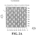
- the fiber bundle 10 includes a plurality of fiber bundles 10 extending in different directions in the subject T.
- the subject T has a structure in which the fiber bundle 10a extending in the Y-direction and a fiber bundle 10b extending in the X-direction are knitted.
- the fiber bundle 10a and the fiber bundle 10b are shown in a distinguishable manner, but in reality, they are carbon fibers of the same type woven (or knitted) into a sheet.
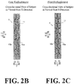
- FIG. 2B is a cross-sectional view of the subject T as viewed from the X direction.
- the fiber bundles 10a extend in the Y-direction and are knitted in the fiber bundles 10b.
- FIG. 2C is a cross-sectional view of the subject T as viewed from the Y-direction.
- the fiber bundles 10b extend in the X-direction and are knitted in the fiber bundles 10a.
- the subject T has a structure in which a plurality of sheets in which fiber bundles 10a extending in the Y-direction and fiber bundles 10b extending in the X-direction are knitted is stacked in the Z-direction.
- the resin 11 which is a base metal of the subject T (CFRP) covers the surface of the subject T. Further, the resin 11 fills the gap between the fiber bundles 10 inside the subject T.
- FIG. 3 is a schematic diagram showing the relationship between the subject T and the grating direction of the gratings when the subject T is imaged in the X-ray imaging apparatus 100 according to the first embodiment of the present invention.
- the first grating 2 and the second grating 3 are arranged so that the grating directions extend in the lateral direction (X-direction).
- the subject T is illustrated only by the fiber bundles 10b extending in the X-direction.
- the fiber bundles 10a are arranged in a direction (Y-direction) orthogonal to the grating direction of the gratings.
- FIG. 4A is a schematic diagram showing an example in which the fiber bundle 10b of the subject T is arranged so as to be orthogonal to the optical axis of the X-rays.
- FIG. 4B is a cross-sectional view taken along the line 400-400 in FIG. 4A .
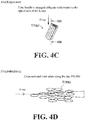
- FIG. 4C is a schematic diagram showing an example in which the fiber bundle 10b of the subject T is arranged so as to be oblique to the optical axis of the X-rays in the XZ-plane.
- FIG. 4D is a cross-sectional view taken along the line 500-500 in FIG. 4C .
- the X-rays when X-rays are incident on the fiber bundle 10 extending in a direction orthogonal to the optical axis of the X-rays, the X-rays diffuse by the fiber bundle 10. Specifically, at the interface between the fiber in the subject T and the resin 11, the X-rays are refracted by the difference of the refractive index between the fiber and the resin 11. Since the fiber bundles 10 are laminated in the subject T and since the fiber bundle 10 is composed of a large number of fibers, when the X-rays pass through many fibers, multiple refraction occurs and the X-rays diffuse.
- the fiber bundle 10b is arranged so as to be orthogonal to the optical axis of the X-rays. That is, the fiber bundle 10b is arranged so as to extend in the X-direction. Therefore, as shown in FIG. 4B , the cross-section of the fiber is substantially circular. In the example shown in FIG. 4C , the fiber bundle 10b is arranged obliquely with respect to the optical axis of the X-rays. Therefore, as shown in FIG. 4D , the cross-section of the fiber is elliptical.
- the distance through which the X-rays pass through the interface between the fiber and the resin 11 becomes longer as compared with the case in which the cross-section of the fiber is substantially circular. Further, the interface between the fiber and the resin 11 has a rough shape, and the diffusion of X-rays is increased by the distance that the X-rays pass through the interface between the fiber and the resin 11 becomes long.
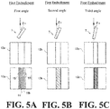
- FIG. 5 is schematic diagrams A to C showing an absorption image 12 and a dark field image 13 at certain angles (first angle ⁇ 1 , second angle ⁇ 2 and third angle ⁇ 3 ) captured while rotating the subject T in the X-ray imaging apparatus 100 according to the first embodiment.
- the fiber bundle 10 absorbs the X-rays regardless of the direction of the fiber bundle 10. For this reason, it is difficult to grasp the detailed structure of the fiber bundle 10 inside the subject T.
- the structure of the fiber bundle 10b included in the area 14 where the fiber bundles 10 are knitted is visualized in the dark field image 13a to the dark field image 13c. Further, since the fiber bundle 10 and the resin 11 are different in refractive indexes of the X-rays, in the dark field image 13, a contrast is obtained between the fiber bundle 10 and the resin 11. Therefore, in the dark field image 13, the area 15 by the resin 11 is also visualized.
- the diffusion of the X-rays increases or decreases according to the relative relationship between the grating direction of the plurality of gratings and the orientation of the subject T.
- the subject T since the subject T is rotated one turn, it becomes possible to image at an angle at which the diffusion of the X-rays increases, and it is possible to obtain a dark field image 13 in which the fiber bundle 10 is emphasized.
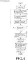
- Step S1 an operator places the subject T on the rotation mechanism 7.
- Step S2 the control unit 6 rotates the subject T by a predetermined angle via the rotation mechanism 7.
- Step S3 the control unit 6 images the subject T while moving the first grating 2 stepwise via the grating moving mechanism 8.
- the image processing unit 5 generates an absorption image 12 and a dark field image 13 of the subject T.
- Step S5 the control unit 6 determines whether or not the rotation mechanism 7 has rotated the subject T by 360 degrees. When the subject T has not been rotated by 360 degrees, it returns to Step S2. When the subject T has been rotated by 360 degrees, it proceeds to Step S6.
- Step S6 the image processing unit 5 reconstructs the absorption image 12 and the dark field image 13 captured in each rotation angle, and generates three-dimensional data (3D data) of the subject T.
- Step S7 the image processing unit 5 performs correction processing including at least smoothing processing on the generated three-dimensional data.
- the smoothing processing includes, for example, smoothing by filtering with a Gaussian filter or the like.
- Step S8 the image processing unit 5 generates a three-dimensional absorption image 20 (see FIG. 9A ) and a three-dimensional dark field image 21 (see FIG. 9B ). Specifically, the image processing unit 5 determines the boundary between the subject T and the background by analyzing the generated three-dimensional data. The image processing unit 5 extracts the three-dimensional data of the fiber bundle 10b extending in a direction along the plurality of grating directions. As a result, the image processing unit 5 generates the three-dimensional absorption image 20 and the three-dimensional dark field image 21.
- a method of determining the boundary between the subject T and the background uses, for example, threshold processing for extracting data whose voxel value of three-dimensional data of the subject T is equal to or more than a predetermined value as data of the fiber bundle 10.
- the image processing unit 5 acquires the feature amount of the fiber bundle 10.
- the feature amount related to the fiber bundle 10 includes at least one or more of the knitting height H of the fiber bundle 10 (see FIG. 8B ), the size S of the gap between adjacent fiber bundles 10 (see FIG. 8B ), the width W (see FIG. 9B ) of the fiber bundle 10, the length L (see FIG. 9B ) of the fiber bundle 10, the curvature C of the fiber bundle 10 (see FIG. 9B ), and the thickness P of the fiber bundle 10 (see FIG. 9B ).
- a tensor analysis etc.
- the image processing unit 5 is configured to extract the three-dimensional data of the fiber bundle 10 extending in a direction along the grating direction of the plurality of gratings. Specifically, the image processing unit 5 is configured to extract the three-dimensional data of the fiber bundle 10 from the three-dimensional data generated from the dark field image 13 captured by relatively rotating the subject T with respect to the imaging system 23 about an axis AR of the vertical direction orthogonal to the grating direction of the plurality of gratings. Further, the image processing unit 5 is configured to determine the boundary between the subject T and the background by analyzing the three-dimensional data and extract the three-dimensional data of the fiber bundle 10 in a direction along the grating direction of the plurality of gratings.
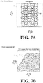
- FIG. 7A is a schematic diagram of the tomogram 16 of the three-dimensional absorption image 20.
- FIG. 7B is a perspective view of the three-dimensional image 17 obtained by imaging the surface of the three-dimensional absorption image 20.
- X-rays are absorbed irrespective of the extending direction of the fiber bundle 10. Therefore, not only the fiber bundle 10b extending in the X-direction but also the fiber bundle 10a extending in the Y-direction are visualized.
- the contrast of the fiber bundle 10 and that of the resin 11 become substantially the same in the three-dimensional image 17, which also visualizes the resin 11. Therefore, the knitting shape of the fiber bundles 10 cannot be grasped.
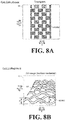
- FIG. 8A is a schematic diagram of the tomogram 18 of the three-dimensional dark field image 21.
- FIG. 8B is a perspective view of the three-dimensional image 19 obtained by imaging the surface of the three-dimensional dark field image 21.
- the fiber bundles 10b extend in a direction along the grating direction of the plurality of gratings, the diffusion of the X-rays by the fiber bundles 10b increases, which enhances the contrast of the fiber bundles 10b. Therefore, in the tomogram 18 of the three-dimensional dark field image 21, only the fiber bundles 10b extending in the X-direction can be visualized.
- the knitting structure of the fiber bundles 10b extending in the X-direction can be confirmed.
- the image processing unit 5 can acquire the knitting height H of the fiber bundle 10 and the size S of the gap between the adjacent fiber bundles 10 as the feature amount of the fiber bundle 10b.
- the knitting height H of the fiber bundle 10 denotes a length between the mountain part and the valley part of the knitted part (the intersecting part of the fiber bundle 10a and fiber bundle 10b) of the fiber bundle 10.
- the size S of the gap between adjacent fiber bundles 10 denotes a length between one peak (valley) portion and the other valley (peak) portion of the adjacent fiber bundles 10.
- the image processing unit 5 is configured to detect the boundary of the fiber bundle 10 and highlight the boundary of the fiber bundle 10 in the dark field image 13.
- the image processing unit 5 highlights the boundary of the fiber bundle 10 by displaying the boundary of the fiber bundle 10 with a bold line, but the method of highlighting the boundary of the fiber bundle 10 may be any method.
- the boundary of the fiber bundle 10 may be highlighted in the tomogram 18 of FIG. 8A .
- the boundary of the fiber bundle 10 may be emphasized by changing the color of the boundary of the fiber bundle 10.
- the image processing unit 5 is configured to acquire the number of fiber bundles 10 within the area-of-interest in the subject T, the distance FD between the boundaries of the fiber bundle 10, the surface area SA (the area of the hatched area), and the density of the fiber bundle 10.
- the area-of-interest is an area in which an operator can specify an arbitrary position and a size in three-dimensional data.
- the number of fiber bundles 10 denotes the number of fiber bundles 10 extending in a direction along the grating direction of the plurality of gratings in the dark field image 13.
- the distance FD between the boundaries of the fiber bundle 10 is the distance between the boundaries of the opposing fiber bundles 10.
- the density of the fiber bundle 10 denotes the ratio of the area occupied by the fiber bundle 10 (10b) in the tomogram 18.
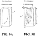
- FIG. 9A is a schematic diagram of a three-dimensional absorption image 20 in which the subject T not knitted with fiber bundles 10 is imaged in the subject T.
- FIG. 9B is a schematic diagram of a three-dimensional dark field image 21 in which the subject T not knitted with fiber bundles 10 in the subject T is imaged.
- the fiber bundle 10 inside the subject T cannot be clearly confirmed.
- the fiber bundle 10 inside the subject T can be confirmed by the difference of the refractive index between the fiber bundle 10 and the resin 11.
- the image processing unit 5 can acquire, as the feature amounts of the fiber bundle 10, the width W of the fiber bundle 10, the length L of the fiber bundle 10, the curvature C of the fiber bundle 10, and the thickness P of the fiber bundle 10.
- the width W of the fiber bundle 10 denotes the maximum length of the fiber bundle 10 in the transverse direction.
- the length L of the fiber bundle 10 denotes the maximum length of the fiber bundle 10 in the longitudinal direction.
- the curvature C of the fiber bundle 10 denotes the degree of curvature at the end surface, etc., of the fiber bundle 10.
- the thickness P of the fiber bundle 10 denotes the length of the fiber bundle 10 in the thickness direction (Z-direction).
- the X-ray imaging apparatus 100 is provided with the X-ray source 1, a plurality of gratings including the first grating 2 for forming a self-image by the X-rays emitted from the X-ray source 1 and the second grating 3 for interfering with the self-image of the first grating 2, the detector 4 for detecting the X-rays irradiated from the X-ray source 1, the subject T including the fiber bundle 10, a rotation mechanism 7 for relatively rotating the subject T including the fiber bundle 10 and the imaging system 23 composed of the X-ray source 1, the detector 4, and the image processing unit 5 for generating at least the dark field image 13 from the intensity distribution of the X-rays detected by the detector 4.
- the image processing unit 5 is configured to generate three-dimensional data from a plurality of dark field images 13 captured at a plurality of rotation angles while relatively rotating the subject T by the rotation mechanism 7, and acquire at least three-dimensional dark field image 21 of the subject T including the fiber bundle 10 by analyzing the X-ray intensity in the generated three-dimensional data.
- the dark field image 13 is an image that visualizes the microstructure (such as a fiber bundle 10) in the subject T by X-ray diffusion.
- the fiber bundle 10 can be confirmed according to the dark field image 13.
- the subject T can be imaged without reducing the dose of the X-ray source 1. With this, even in the case of using an X-ray source 1 with a large dose and imaging at a low magnification ratio, the fiber bundle 10 in the subject T can be imaged.
- the image processing unit 5 is configured to extract the three-dimensional data of the fiber bundle 10 extending in a direction along the grating direction of the plurality of gratings.
- the dark field image 13 denotes an image based on the change of the dose of the X-rays for each pixel of the detector 4 caused by the diffusion of the X-rays. That is, the X-rays transmitted through the grating and detected by the detector 4 are diffused and the diffused X-rays are absorbed by the grating, and therefore the diffused part of the X-rays becomes undetectable by the detector 4.
- the diffused X-rays pass through the grating, so the X-rays diffused and transmitted through the grating becomes detectable by the detector 4. Therefore, in the dark field image 13, the dose of X-rays to be detected in each pixel of the detector 4 changes.
- the change of the dose of X-rays detected by the detector 4 becomes remarkable.
- the diffusion of the X-rays is caused by multiple refraction of the X-rays by the microstructure inside the subject T (fiber bundle 10, etc.).
- the refraction of the X-rays occurs when the X-rays pass through the boundary of the area different in refractive index.
- the X-rays are refracted by the fiber bundle 10
- the X-rays are refracted by the boundary between the fiber bundle 10 and the resin 11, so that the X-rays are refracted in a direction intersecting with the direction in which the fiber bundle 10 extends.
- the dark field image 13 it is possible to grasp the directivity of the diffusion of the X-rays. Therefore, the directivity of the X-ray diffusion by the fiber bundle 10 makes it possible to separate the fiber bundle 10 extending in a specific direction from the fiber bundle 10 or the like extending in another direction.
- the fiber bundle 10 extending in a direction along the grating direction of the gratings can be extracted in a separable manner from the fiber bundle 10 extending in a direction other than the grating direction of the grating. Therefore, as described above, by extracting the three-dimensional data of the fiber bundle 10 extending in a direction along the grating direction of the grating among the fiber bundle 10 in the subject T, the shape, the arrangement, etc., of the fiber bundle 10 in the subject T can be grasped in detail.
- the image processing unit 5 is configured to extract the three-dimensional data of the fiber bundle 10 from the three-dimensional data generated from the dark field image 13 captured by relatively rotating at least the subject T with respect to the imaging system 23 about an axis AR of the vertical direction orthogonal to the grating direction of the plurality of gratings.
- the incident angle of the X-rays incident on the fiber bundle 10 changes.
- the image processing unit 5 is configured to analyze the three-dimensional data to determine the boundary between the subject T and the background and extract the three-dimensional data of the fiber bundle 10 in a direction along the grating directions of the plurality of gratings. With this configuration, it is possible to easily extract the three-dimensional data of the fiber bundle 10 from the obtained three-dimensional data.
- the image processing unit 5 is configured to obtain the feature amount related to the fiber bundle 10 in the subject T, and the feature amount related to the fiber bundle 10 includes at least one or more of the knitting height H of the fiber bundle 10, the size S of the gap between adjacent fiber bundles 10, the width W of the fiber bundle 10, the length L of the fiber bundle 10, the curvature C of the fiber bundle 10, and the thickness P of the fiber bundle 10.
- the image processing unit 5 is configured to highlight the boundary of the fiber bundle 10 and acquire one or more of the boundary density of the fiber bundle 10 in the area-of-interest in the subject T, the surface area SA of the fiber bundle 10, and the density of the fiber bundle 10 based on the boundary of the fiber bundle 10.
- the image processing unit 5 is configured to perform correction processing including at least smoothing processing on the generated three-dimensional data before acquiring the feature amount.
- the X-ray imaging apparatus 100 is further provided with a grating moving mechanism 8 for moving the grating stepwise, and the grating moving mechanism 8 is configured to move the first grating 2 stepwise in the grating plane in a direction orthogonal to the grating direction.
- the grating moving mechanism 8 is configured to move the first grating 2 stepwise in the grating plane in a direction orthogonal to the grating direction.
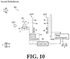
- the configuration of the X-ray imaging apparatus 200 according to the second embodiment of the present invention will be described with reference to FIG. 10 to FIG. 12 .
- the X-ray imaging apparatus 200 is configured to extract a plurality of fiber bundles 10 extending in different directions.
- the same reference numerals are allotted to the same configurations as those of the first embodiment, and the description thereof will be omitted.
- the X-ray imaging apparatus 200 in the second embodiment is further provided with a direction changing mechanism 22 for relatively changing the grating direction of the plurality of gratings and the orientation of the subject T.
- the direction changing mechanism 22 is configured to relatively change the grating direction of the plurality of gratings and the orientation of the subject T based on the signal from the control unit 60.
- the direction changing mechanism 22 is arranged on the rotation mechanism 7, and the rotation mechanism 7 relatively rotates the subject T together with the direction changing mechanism 22 about the axis AR.
- the direction changing mechanism 22 includes a drive unit 22a, a frame 22b, and a subject holder 22c.
- the drive unit 22a is configured to rotate the subject holder 22c by a predetermined angle based on the signal from the control unit 60.
- the drive unit 22a includes, for example, a stepping motor and the like.
- the subject holder 22c is configured to rotate in the XY-plane by the drive unit 22a in the direction along the circumferential direction of the frame 22b.
- the subject holder 22c is configured such that one end is supported by the frame 22b and the other end holds the subject T.
- the direction changing mechanism 22 rotates the subject holder 22c by 90 degrees in the XY-plane via the drive unit 22a based on the signal from the control unit 60 to thereby change the orientation of the subject T from the state of holding the subject T horizontally to the state of holding the subject T vertically.
- the image processing unit 5 is configured to separately extract the three-dimensional data of the fiber bundle 10 extending in different directions from the three-dimensional data of the dark field image 13 captured plural times by changing the direction of the subject T so that different directions of the subject T are along the grating directions of the plurality of gratings.
- the orientation of the subject T is changed by the direction changing mechanism 22.
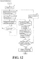
- Step S1 to S9 the subject T is imaged while rotating 360 degrees to generate a three-dimensional dark field image 21. Thereafter, the process proceeds to Step S10.
- Step S10 the control unit 60 determines whether or not imaging has been performed a predetermined number of times by changing the grating direction of the plurality of gratings and the orientation of the subject T.
- the process proceeds to Step S11.
- the process proceeds to Step S12.
- Step S11 the control unit 6 changes the grating direction of the plurality of gratings and the orientation of the subject T via the direction changing mechanism 22.
- the control unit 6 changes the grating direction of the plurality of gratings and the orientation of the subject T via the direction changing mechanism 22.
- the grating direction of the plurality of gratings and the orientation of the subject T are changed. Thereafter, the process returns to Step S2.
- Step S12 the image processing unit 5 changes the grating direction of the plurality of gratings and the orientation of the subject T and synthesize a plurality of three-dimensional dark field images 21 generated by changing the grating direction of the plurality of gratins and the orientation of the subject T.
- the image processing unit 5 is configured to separately extract the three-dimensional data of the plurality of fiber bundles 10 extending in different directions from the three-dimensional data of the dark field image 13 captured plural times while relatively changing the grating directions of the plurality of gratins and the orientation of the subject T by the direction changing mechanism 22 and separately generate the three-dimensional dark field image 21 based on the extracted three-dimensional data.
- the image processing unit 5 is configured to synthesize the plurality of three-dimensional dark field images 21 generated from the plurality of the three-dimensional data based on the fiber bundle 10 extending in mutually different directions. Specifically, the image processing unit 5 separately extracts the fiber bundles 10 extending in mutually different directions. The image processing unit 5 displays the fiber bundles 10 extracted separately from each other. The image processing unit 5 synthesizes the fiber bundles 10 that are distinguishably displayed and extend in mutually different directions as shown in FIG. 2A .
- the fiber bundles 10 include fiber bundles 10 extending in a plurality of different directions in the subject
- the image processing unit 5 is configured to extract the three-dimensional data of the fiber bundle 10 extending in different directions from the three-dimensional data of the dark field image 13 captured by changing the orientation of the subject T so that different directions of the subject T are along the grating direction of the plurality of gratings.
- any one of the plurality of fiber bundles 10 in the subject T can be made to extend along the grating direction of the grating.
- the fiber bundles 10 different in direction can be separately visualized.
- the X-ray imaging apparatus 200 is further provided with the direction changing mechanism 22 for relatively changing the grating direction of the plurality of gratings and the orientation of the subject T.
- the direction changing mechanism 22 for example, the orientation of the subject T and the grating direction of the plurality of gratings can be easily changed without changing the orientation of the subject T by an operator.
- the dark field image 13 it is possible to visualize the plurality of fiber bundles 10 extending in different directions included in the subject T.
- the image processing unit 5 is configured to separately extract the three-dimensional data of the plurality of fiber bundles 10 extending in different directions from the three-dimensional data of the dark field image 13 captured plural times while relatively changing the grating directions of the plurality of gratins and the orientation of the subject T by the direction changing mechanism 22 and separately generate the three-dimensional dark field image 21 based on the extracted three-dimensional data.
- the dark field image 13 visualizing the plurality of fiber bundles in the subject T can be easily generated.
- the image processing unit 5 is configured to synthesize the plurality of three-dimensional dark field images 21 generated from the plurality of the three-dimensional data based on the fiber bundle 10 extending in mutually different directions. With this configuration, it is possible to confirm the plurality of three-dimensional dark field images 21 based on fiber bundles 10 extending in different directions with one three-dimensional image 21, so that it is possible to grasp the plurality of fiber bundles 10 in the subject T in detail.
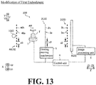
- a third grating 40 may be provided between the X-ray source 1 and the first grating 2.
- the third grating 40 has a plurality of slits 40a and X-ray absorption portions 40b arranged at a predetermined period (pitch) d3 in the Y-direction.
- the slits 40a and the X-ray absorption portions 40b are each formed so as to extend linearly.
- the slits 40a and the X-ray absorption portions 40b are each formed so as to extend in parallel. Further, the third grating 40 is arranged between the X-ray source 1 and the first grating 2 and is irradiated by the X-rays from the X-ray source 1.
- the third grating 40 is configured to use the X-rays that have passed through the respective slits 40a as line light sources corresponding to the positions of the respective slits 40a. With this, the third grating 40 can enhance the coherence of the X-rays emitted from the X-ray source 1. With this, the third grating 40 can enhance the coherence of the X-rays emitted from the X-ray source 1. As a result, it is possible to form the self-image of the first grating 2 without depending on the focal length of the X-ray source 1, so that the freedom of selection of the X-ray source 1 can be improved.
- the rotation mechanism 7 rotates the subject T with respect to the imaging system 23 by rotating the subject T
- the present invention is not limited thereto.
- it may be configured to rotate the subject T relative to the imaging system 23 by rotating the imaging system 23.
- the direction changing mechanism 22 relatively changes the grating direction of the plurality of gratings and the orientation of the subject T by rotating the subject T
- the present invention is not limited thereto.
- it may be configured to relatively change the grating direction of the plurality of gratings and the orientation of the subject T by holding each grating by the plurality of direction changing mechanisms 22 and rotating each grating.
- the relative position of each grating may sometimes is displaced. In such a case, it is necessary to finely adjust the grating position. Therefore, it is preferably configured to change the grating direction of the plurality of gratings and the orientation of subject T by changing the orientation of the subject T.
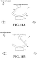
- the direction changing mechanism 22 changes the orientation of the subject T from the horizontal state to the vertical state, but the present invention is not limited thereto.
- the orientation of the subject T may be set to an arbitrary orientation.
- the image processing unit 5 separately generates a three-dimensional dark field image 21 when the subject T is arranged horizontally and a three-dimensional dark field image 21 when the subject T is arranged vertically, and the plurality of generated three-dimensional dark field images 21 is synthesized, but the present invention is not limited thereto.
- a plurality of three-dimensional dark field images 21 may be generated by arranging the subject T at an arbitrary angle other than the horizontal direction and the vertical direction and the generated three-dimensional dark field images 21 are synthesized.
- the present invention is not limited to this. Any grating among the plurality of gratings may be moved stepwise.
- the dark field image 13 is generated by moving the first grating 2 stepwise in a direction orthogonal to the grating direction in the grating plane, but the present invention is not limited to this.
- it may be configured to generate the dark field image 13 by a moire single shooting technique of capturing images by rotating any one of a plurality of gratings in an XY-plane to form a moire fringe.
- a phase grating is used as the first grating 2
- an absorption grating may be used as the first grating 2.
- CFRP carbon fiber reinforced plastic
- GFRP glass fiber reinforced plastic
- Any subject may be used as long as a fiber bundle is included in the subject to be imaged.
- the feature amount related to the fiber bundle 10 includes at least one or more of the knitting height H of the fiber bundle 10, the size S of the gap between adjacent fiber bundles 10, the width W of the fiber bundle 10, the length L of the fiber bundle 10, the curvature C of the fiber bundle 10, and the thickness P of the fiber bundle, but the present invention is not limited thereto.
- the knitting regularity of the fiber bundles 10 may be extracted as the feature amount.
- the present invention is not limited thereto.
- it may be configured such that the rotation mechanism 7 is arranged in the subject holder 22c of the direction changing mechanism 22 and the subject T is arranged on the rotation mechanism 7.
- the present invention is not limited to this.
- it may be configured such that the grating direction of the grating is arranged in the vertical direction (Y-direction) and the direction of the axis AR when rotating the subject T is arranged in a direction along the grating direction of the grating (Y-direction) .
Landscapes
- Health & Medical Sciences (AREA)
- Life Sciences & Earth Sciences (AREA)
- Engineering & Computer Science (AREA)
- Medical Informatics (AREA)
- Pathology (AREA)
- General Health & Medical Sciences (AREA)
- Physics & Mathematics (AREA)
- Nuclear Medicine, Radiotherapy & Molecular Imaging (AREA)
- Radiology & Medical Imaging (AREA)
- Chemical & Material Sciences (AREA)
- Molecular Biology (AREA)
- Animal Behavior & Ethology (AREA)
- Veterinary Medicine (AREA)
- Public Health (AREA)
- Surgery (AREA)
- Heart & Thoracic Surgery (AREA)
- Biomedical Technology (AREA)
- Optics & Photonics (AREA)
- Biophysics (AREA)
- High Energy & Nuclear Physics (AREA)
- Immunology (AREA)
- General Physics & Mathematics (AREA)
- Analytical Chemistry (AREA)
- Biochemistry (AREA)
- Pulmonology (AREA)
- Theoretical Computer Science (AREA)
- Crystallography & Structural Chemistry (AREA)
- Mechanical Engineering (AREA)
- Composite Materials (AREA)
- Computer Vision & Pattern Recognition (AREA)
- Analysing Materials By The Use Of Radiation (AREA)
- Measurement Of Radiation (AREA)
Abstract
Description
- The present invention relates to an X-ray imaging apparatus, and more particularly to an X-ray imaging apparatus for imaging a fiber bundle in a subject by performing tomography.
- Conventionally, an X-ray imaging apparatus for imaging a fiber bundle in a subject by performing tomography is known. Such an X-ray imaging apparatus is disclosed by, for example, "Fiber orientation analysis", [online], [searched on September 5, 2017], Internet <URL: http://www.an.shimadzu.co.jp/ndi/products/x_ryct/smx_225ct_fpd_hr08. htm> (hereinafter referred to as "Non-Patent
Document 1"). - In recent years, fiber reinforced plastics (FRP) using carbon fibers, glass fibers, etc., have been used in industrial products and sports products. In manufacturing products using FRP, there is a need for a quality inspection device for inspecting the quality, etc., of the manufactured products. Under the circumstances, in the aforementioned
Non-Patent Document 1, in order to carry out a detailed inspection of a subject by an absorption image, the subject is imaged under the imaging conditions capable of imaging each of the fibers included in a fiber bundle, and the fibers included in the fiber bundle are directly observed. To do this, it is necessary to reduce the focal spot size of the X-ray source and enhance the resolution of the detector. Specifically, in order to image a single thin fiber in the fiber bundle in the subject, it is necessary to use a micro-focus tube with a small focal spot size as an X-ray source and use a high resolution detector. - However, in the aforementioned
Non-Patent Document 1, since the subject is imaged in a magnified manner to observe the fiber bundle, there is a disadvantage that the visual field area of the subject which can be observed at once becomes narrow. For this reason, there is a problem that it is impossible to grasp the entire length of a long fiber bundle and/or the entire shape of the fiber bundle by one imaging. Further, the X-ray imaging apparatus disclosed in Non-PatentDocument 1 uses a micro-focus tube having a small focal diameter (high resolution) in order to image fine fibers. Therefore, there is a problem that the dose of X-rays to be irradiated is reduced and therefore the obtained image is less likely to be contrasted. - The present invention has been made to solve the aforementioned problems, and one object of the present invention is to provide an X-ray imaging apparatus capable of imaging a fiber bundle in a subject even when using an X-ray source with a large dose and imaging with a low magnification ratio.
- In order to attain the aforementioned object, an X-ray imaging apparatus according to one aspect of the present invention includes an X-ray source, a plurality of gratings including a first grating for forming a self-image by X-rays irradiated from the X-ray source and a second grating for interfering with the self-image of the first grating, a detector configured to detect the X-rays irradiated from the X-ray source, a rotation mechanism configured to relatively rotate a subject including a fiber bundle and an imaging system constituted by the X-ray source, the detector, and the plurality of gratings, and an image processor configured to generate at least a dark field image from an intensity distribution of the X-rays detected by the detector, wherein the image processor is configured to generate three-dimensional data from a plurality of the dark field images captured at a plurality of rotation angles while relatively rotating the subject and the imaging system by the rotation mechanism and acquire at least three-dimensional dark field image of the subject including the fiber bundle by analyzing X-ray intensity in the generated three-dimensional data. Note that the "dark field image" denotes a visibility image obtained by a visibility change based on small-angle scattering of an object. Further, the dark field image is also called a small-angle scattering image. The "visibility" denotes sharpness.
- In the X-ray imaging apparatus according to one aspect of the present invention, as described above, the apparatus further includes the image processor configured to generate three-dimensional data from a plurality of the dark field images captured at a plurality of rotation angles while relatively rotating the subject and the imaging system by the rotation mechanism and acquire at least three-dimensional dark field image of the subject including the fiber bundle by analyzing the X-ray intensity in the generated three-dimensional data. Here, the dark field image is an image that visualizes the microstructure (such as a fiber bundle) in the subject by X-ray diffusion. Therefore, even in cases where fine fibers cannot be resolved in a normal absorption image by imaging conditions, such as, e.g., a focal spot size and a magnification ratio of X-rays, the X-rays are diffused by the fiber bundle, and therefore the fiber bundle can be confirmed according to the dark field image. In other words, it becomes possible to observe the fiber bundle without imaging the subject by magnifying it until a single one fiber contained in the fiber bundle can be imaged. Further, since it becomes possible to image the fiber bundle without magnifying the subject, the subject can be imaged without reducing the dose of the X-ray source. With this, even in the case of using an X-ray source with a large dose and imaging at a low magnification ratio, the fiber bundle in the subject can be imaged.
- In the X-ray imaging apparatus according to the aforementioned one aspect of the present invention, the image processor is preferably configured to analyze the X-ray intensity in the generated three-dimensional data to extract the three-dimensional data of the fiber bundle extending in a direction along a grating direction of the plurality of gratings and acquire the three-dimensional dark field image of the subject including the fiber bundle based on the extracted three-dimensional data. Here, the dark field image is an image based on the change of the dose of the X-rays for each pixel of the detector caused by the diffusion of the X-rays. That is, the X-rays transmitted through the gratings and detected by the detector are diffused and the diffused X-rays are absorbed by the grating, and therefore the diffused part of the X-rays becomes undetectable by the detector. On the other hand, since the X-rays which were used to be absorbed by the gratings is diffused, the diffused X-rays pass through the grating, so the X-rays diffused and transmitted through the grating becomes detectable by the detector. Therefore, in the dark field image, the dose of X-rays to be detected in each pixel of the detector changes. When the X-rays are diffused in a direction orthogonal to the grating direction of the grating, the change of the dose of X-rays detected by the detector becomes remarkable. The X-ray diffusion is caused by multiple refraction of X-rays by the microstructure (fiber bundle, etc.) inside the subject. The refraction of X-rays occurs when X-rays pass through the boundary of the area different in refractive index. When the X-rays are refracted by the fiber bundle, the X-rays are refracted by the boundary between the fiber bundle and the other area, so that the X-rays are refracted in a direction intersecting with the direction in which the fiber bundle extends. With this, in the dark field image, it is possible to capture the directivity of the diffusion of X-rays. Therefore, the directivity of the X-ray diffusion by the fiber bundle makes it possible to separate the fiber bundle extending in a specific direction from a fiber bundle or the like extending in another direction. That is, in the dark field image, the fiber bundle extending in a direction along the grating direction of the grating can be extracted in a separable manner from a fiber bundle, etc., extending in a direction other than the grating direction of the grating. Therefore, by extracting the three-dimensional data of the fiber bundle extending in a direction along the grating direction of the grating among the fiber bundles in the subject as described above, the shape and/or the arrangement of the fiber bundle in the subject can be grasped in detail.
- In this case, the image processor is preferably configured to extract the three-dimensional data of the fiber bundle from the three-dimensional data generated from the dark field image captured by relatively rotating at least the subject with respect to the imaging system about an axis of a vertical direction orthogonal to a grating direction of the plurality of gratings. Here, by rotating the subject with respect to the imaging system, the incident angle of the X-rays incident on the fiber bundle changes. Compared with the case in which the optical axis of the X-rays and the fiber bundle are perpendicular to each other, in the process of the relative rotation, when the X-rays are incident obliquely to the fiber bundle, an area through which the X-rays transmit the boundary surface between the fiber bundle and the area other than the fiber bundle becomes longer, and the diffusion of the X-rays becomes stronger. Therefore, with the aforementioned configuration, it is possible to image at the angle at which the fiber bundle in the subject most diffuses the X-rays. As a result, in the dark field image, the fiber bundle can be clearly visualized.
- In the X-ray imaging apparatus according to the aforementioned one aspect of the present invention, it is preferably configured such that the fiber bundle include the fiber bundles extending in a plurality of different directions in the subject and the image processor is configured to extract the three-dimensional data of the fiber bundles extending in different directions from the three-dimensional data of the dark filed image captured by changing either one of the grating direction of the plurality of gratins and an orientation of the subject so that different directions of the subject are along the grating directions of the plurality of gratings. With this configuration, any one of the plurality of fiber bundles in the subject can be arranged along the grating direction of the grating. As a result, in the acquired dark field image, the fiber bundles different in direction can be separately visualized.
- In the X-ray imaging apparatus according to the aforementioned one aspect of the present invention, it is preferable to further include a direction changing mechanism configured to change either one of the grating direction of the plurality of gratings and the orientation of the subject. With this structure, by using the direction changing mechanism, for example, an operator can easily change the orientation of the subject and the grating direction of the plurality of gratings without changing the orientation of the subject. As a result, in the dark field image, it is possible to visualize a plurality of fiber bundles extending in different directions included in the subject.
- In the X-ray imaging apparatus according to the aforementioned one aspect of the present invention, the image processor is preferably configured to separately extract the three-dimensional data of the plurality of fiber bundles extending in different directions from the three-dimensional data of the dark field image captured plural times while relatively changing the grating direction of the plurality of gratins and the orientation of the subject by the direction changing mechanism and separately generate the three-dimensional dark field image. With this configuration, the dark field image visualizing the plurality of fiber bundles in the subject can be easily generated.
- In the X-ray imaging apparatus according to the aforementioned one aspect of the present invention, the image processor is preferably configured to synthesize the plurality of three-dimensional dark field images generated from the plurality of the three-dimensional data based on the fiber bundles extending in mutually different directions. With this configuration, it is possible to confirm a plurality of three-dimensional dark field images based on fiber bundles extending in different directions with one three-dimensional image, so that it is possible to grasp a plurality of fiber bundles in the subject in detail.
- In the X-ray imaging apparatus according to the aforementioned one aspect of the present invention, the image processor is preferably configured to analyze the three-dimensional data to determine a boundary between the subject and a background and extract the three-dimensional data of the fiber bundle in a direction along the grating direction of the plurality of gratings. With this configuration, it is possible to easily extract three-dimensional data of the fiber bundle from the obtained three-dimensional data.
- In the X-ray imaging apparatus according to the aforementioned one aspect of the present invention, the image processor is preferably configured to obtain a feature amount related to the fiber bundle in the subject, and the feature amount related to the fiber bundle includes at least one or more of a knitting height of the fiber bundle, a size of a gap between adjacent fiber bundles, a width of the fiber bundle, a length of the fiber bundle, a curvature of the fiber bundle, and a thickness of the fiber bundle. With this configuration, it is possible to grasp the shape of the fiber bundle in the subject. As a result, it is possible to confirm whether or not the subject is formed as designed. Here, the knitting height of the fiber bundle denotes a length between a mountain part and a valley part of the knitted part (the intersecting part of fiber bundles) of the fiber bundle. Further, the size of the gap between adjacent fiber bundles denotes a length between one peak (valley) part and the other valley (peak) part of adjacent fiber bundles. A width of the fiber bundle denotes the maximum length of the fiber bundle in the lateral direction. The length of the fiber bundle denotes the maximum length of the fiber bundle in the longitudinal direction. The curvature of the fiber bundle denotes the degree of curvature, etc., at the end surface of the fiber bundle. The thickness of the fiber bundle denotes a length of the fiber bundle in the thickness direction.
- In the X-ray imaging apparatus according to the aforementioned one aspect of the present invention, the image processor is preferably configured to highlight a boundary of the fiber bundle and acquire one or more of the number of the fiber bundle in an area-of-interest in the subjects, a distance between boundaries of the fiber bundle, a surface area of the fiber bundle, a density of the fiber bundle based on the boundary of the fiber bundle. With this configuration, it is possible to grasp the quality of the subject by acquiring at least the number of fiber bundles of the subject at the area-of-interest, the distance between the boundaries of the fiber bundle, the surface area of the fiber bundle, and the density of the fiber bundles while making it easy to visually recognize the fiber bundles by highlighting.
- In the X-ray imaging apparatus according to the aforementioned one aspect of the present invention, the image processor is preferably configured to perform correction processing including at least smoothing processing on the generated three-dimensional data before acquiring the feature amount. With this configuration, it becomes possible to eliminate noise, etc., contained in the three-dimensional data, so it is possible to extract the fiber bundle with higher accuracy (accurately).
- In the X-ray imaging apparatus according to the aforementioned one aspect of the present invention, it is preferably configured such that the plurality of gratings further include a third grating arranged between the X-ray source and the first grating. With this configuration, coherence of the X-rays irradiated from the X-ray source can be enhanced by the third grating. As a result, it is possible to form the self-image of the first grating without depending on the focal length of the X-ray source, so that the freedom of selection of the X-ray source can be improved.
- In the X-ray imaging apparatus according to the aforementioned one aspect of the present invention, it is preferably configured to further include a grating moving mechanism configured to move the grating stepwise, wherein the grating moving mechanism is configured to move one of the gratings among the plurality of grating stepwise in a direction orthogonal to the grating direction. With such a configuration, it is possible to easily generate a dark field image by imaging while moving any one of the gratings stepwise in a direction orthogonal to the grating direction in the grating plane.
-
-
FIG. 1 is a schematic diagram of an X-ray imaging apparatus according to a first embodiment as viewed from a side. -
FIG. 2A is a cross-sectional view of the subject as viewed from a Z-direction. -
FIG. 2B is a cross-sectional view of the subject as viewed from an X-direction. -
FIG. 2C is a cross-sectional view of the subject as viewed from a Y-direction. -
FIG. 3 is a schematic diagram for explaining the arrangement of the gratings and the fiber bundle of the X-ray imaging apparatus according to the first embodiment. -
FIG. 4A is a schematic diagram in the case where a subject is arranged in a direction orthogonal to the optical axis of the X-rays in the X-ray imaging apparatus according to the first embodiment. -
FIG. 4B is a schematic diagram of a cross-sectional view taken along the line 400-400 inFIG. 4A . -
FIG. 4C is a schematic diagram in the case where the subject is arranged in an direction inclined with respect to the optical axis of the X-rays in the X-ray imaging apparatus according to the first embodiment. -
FIG. 4D is a schematic view of a cross-sectional view taken along the line 500-500 inFIG. 4C . -
FIG. 5A is a schematic diagram of an absorption image and a dark field image captured by rotating an object at a first angle by the X-ray imaging apparatus according to the first embodiment. -
FIG. 5B is a schematic diagram of an absorption image and a dark field image captured by rotating an object at a second angle by the X-ray imaging apparatus according to the first embodiment. -
FIG. 5C is a schematic diagram of an absorption image and a dark field image captured by rotating an object at a third angle by the X-ray imaging apparatus according to the first embodiment. -
FIG. 6 is a flowchart of an imaging method by the X-ray imaging apparatus according to the first embodiment. -
FIG. 7A is a schematic diagram of a tomogram of an absorption image captured by the X-ray imaging apparatus according to the first embodiment. -
FIG. 7B is a schematic diagram of a 3D (three-dimensional) image captured by the X-ray imaging apparatus according to the first embodiment. -
FIG. 8A is a schematic diagram of a tomogram of a dark field image captured by the X-ray imaging apparatus according to the first embodiment. -
FIG. 8B is a schematic diagram of the 3D (three-dimensional) image captured by the X-ray imaging apparatus according to the first embodiment. -
FIG. 9A is a 3D (three-dimensional) absorption image captured by the X-ray imaging apparatus according to the first embodiment. -
FIG. 9B is a 3D (three-dimensional) dark field image captured by the X-ray imaging apparatus according to the first embodiment. -
FIG. 10 is a schematic diagram of an X-ray imaging apparatus according to a second embodiment as seen from a side. -
FIG. 11A is a schematic diagram in the case where the subject is arranged horizontally by the direction conversion mechanism according to the second embodiment. -
FIG. 11B is a schematic diagram in the case where the subject is arranged vertically by the direction conversion mechanism according to the second embodiment. -
FIG. 12 is a flowchart of an imaging method by the X-ray imaging apparatus according to the second embodiment. -
FIG. 13 is a schematic diagram of an X-ray imaging apparatus according to a modification of the first embodiment as viewed from a side. - Hereinafter, embodiments of the present invention will be described with reference to the attached drawings.
- With reference to
FIG. 1 to FIG. 9 , the configuration of anX-ray imaging apparatus 100, the configuration of a subject T, and a method of generating an image including a dark field image by theX-ray imaging apparatus 100 according to a first embodiment will be described. - With reference to
FIG. 1 , first, the configuration of theX-ray imaging apparatus 100 according to the first embodiment of the present invention will be described. - As shown in
FIG. 1 , theX-ray imaging apparatus 100 is an apparatus for imaging an inside of a subject T by utilizing the diffusion of X-rays passed through the subject T. Further, theX-ray imaging apparatus 100 is an apparatus for imaging the inside of the subject T using a Talbot effect. For example, in a nondestructive inspection application, theX-ray imaging apparatus 100 can be used for imaging the inside of the subject T as an object. - The subject T includes a fiber bundle 10 (see
FIG. 2A ) therein. The subject T is, for example, a carbon fiber reinforced plastic (CFRP) in which a carbon fiber is used as afiber bundle 10 and a resin 11 (seeFIG. 2A ) is used as a base metal. Note that the fiber bundle is a bundle of a large number of fibers gathered. In the first embodiment, thefiber bundle 10 is formed in a plate shape by a large number of fibers. - As shown in
FIG. 1 , theX-ray imaging apparatus 100 is provided with anX-ray source 1, afirst grating 2, asecond grating 3, adetector 4, animage processing unit 5, acontrol unit 6, arotation mechanism 7, and a grating movingmechanism 8. Note that in this specification, the direction from theX-ray source 1 to thefirst grating 2 is referred to as a Z2-direction, and the direction opposite thereto is referred to as a Z1-direction. The left-right direction in a plane orthogonal to the Z-direction is referred to as an X-direction, the direction toward the rear side of the paper surface is referred to as an X2-direction, and the direction toward the front side of the paper is referred to as an XI -direction. Further note that the up-and-down direction in the plane orthogonal to the Z-direction is referred to as a Y-direction, the upward direction is referred to as a Y1-direction, and the downward direction is referred to as a Y2-direction. - The
X-ray source 1 is configured to generate X-rays when a high voltage is applied and irradiate the generated X-rays in the Z2-direction. - The
first grating 2 has a plurality ofslits 2a and X-rayphase change portions 2b arranged at a predetermined period (pitch) d1 in the Y-direction. Theslits 2a and X-rayphase change portion 2b are each formed so as to extend linearly. Further, theslits 2a and the X-rayphase change portion 2b are each formed so as to extend in parallel. Thefirst grating 2 is a so-called phase grating. - The
first grating 2 is arranged between theX-ray source 1 and thesecond grating 3 and configured to be irradiated by the X-rays from theX-ray source 1. Thefirst grating 2 is provided to form a self-image (not shown) of thefirst grating 2 by a Talbot effect. When X-rays with coherence pass through the grating where the slits are formed, the image of the grating (self-image) is formed at a position away from the grating by a predetermined distance (Talbot distance). This is called a Talbot effect. - The
second grating 3 includes a plurality ofX-ray transmission portions 3a andX-ray absorption portions 3b arranged in the Y-direction at a predetermined period (pitch) d2. TheX-ray transmission portions 3a and theX-ray absorption portions 3b are each formed so as to extend linearly. Further, theX-ray transmission portions 3a and theX-ray absorption portions 3b are each formed so as to extend in parallel with each other. Thesecond grating 3 is a so-called absorption grating. Thefirst grating 2 and thesecond grating 3 are gratings having different roles, but theslit 2a and theX-ray transmission portion 3a each transmit X-rays. Further, theX-ray absorption portion 3b plays a role of shielding the X-rays, and the X-rayphase change portion 2b changes the phase of the X-rays by the difference of the refractive index with theslit 2a. - The
second grating 3 is arranged between thefirst grating 2 and thedetector 4, and is irradiated by the X-rays that passed through thefirst grating 2. Further, thesecond grating 3 is arranged at a position away from thefirst grating 2 by the Talbot distance. Thesecond grating 3 interferes with the self-image of thefirst grating 2 to form a moire fringe (not shown) on the detection surface of thedetector 4. - The
detector 4 is configured to detect X-rays, convert the detected X-rays into an electric signal, and read the converted electric signal as an image signal. Thedetector 4 is, for example, an FPD (Flat Panel Detector). Thedetector 4 is composed of a plurality of conversion elements (not shown) and a plurality of pixel electrodes (not shown) arranged on the plurality of conversion elements. The plurality of conversion elements and pixel electrodes are arranged in an array manner in the X-direction and Y-direction at a predetermined period (pixel pitch). Further, thedetector 4 is configured to output the acquired image signal to theimage processing unit 5. - The
image processing unit 5 is configured to generate an absorption image 12 (seeFIG. 5A ) and a dark field image 13 (seeFIG. 5A ) based on the image signal output from thedetector 4. Theimage processing unit 5 is an image processor and may be comprised of one or more processors, such as, e.g., a GPU (Graphics Processing Unit) and/or an FPGA (Field-Programmable Gate Array) configured for image processing. - The
control unit 6 is configured to relatively rotate animaging system 23 composed of the subject T, theX-ray source 1, thedetector 4, and a plurality of gratings including thefirst grating 2 and thesecond grating 3 via arotation mechanism 7. Further, thecontrol unit 6 is configured to move thefirst grating 2 stepwise in a grating plane in a direction orthogonal to the grating direction via thegrating moving mechanism 8. Thecontrol unit 6 includes, for example, a processor, such as, e.g., a CPU (Central Processing Unit). - The
rotation mechanism 7 is configured to relatively rotate the subject T and theimaging system 23 based on a signal from thecontrol unit 6. Specifically, therotation mechanism 7 is configured to relatively rotate the subject T with respect to theimaging system 23 by rotating the subject T about the axis AR of the vertical direction orthogonal to the grating direction of the plurality of gratings. The grating direction denotes a direction in which the grating pattern of the grating extends, and in the example shown inFIG. 1 , the X-direction is the grating direction. Further, the grating pattern denotes theslit 2a, the X-rayphase change portion 2b, theX-ray transmission portion 3a, and theX-ray absorption portion 3b of each grating. In the example shown inFIG. 1 , the direction of the axis AR about which therotation mechanism 7 rotates the subject T denotes the Y-direction. Therotation mechanism 7 includes, for example, a rotation stage driven by a motor or the like. - The
grating moving mechanism 8 is configured to move thefirst grating 2 stepwise in the direction (Y-direction) orthogonal to the grating direction in the grating plane (in the XY-plane) based on the signal from thecontrol unit 6. Specifically, the grating movingmechanism 8 moves thefirst grating 2 stepwise by d1/n in which the period d1 of thefirst grating 2 is divided by "n". Thegrating moving mechanism 8 is configured to move thefirst grating 2 stepwise by at least one period d1 of thefirst grating 2. Here, "n" is a positive integer, for example, 9 or the like. Further, the grating movingmechanism 8 includes, for example, a stepping motor and a piezo actuator. - In the first example, the
image processing unit 5 generates an absorption image 12 (seeFIG. 5A ) and a dark field image 13 (seeFIG. 5A ) by imaging while moving thefirst grating 2 stepwise by the grating movingmechanism 8. Here, the absorption image denotes an image of the contrast caused by the difference of the absorption of X-rays by the subject T. Further, the dark field image denotes an image of the contrast caused by the refraction of the X-rays by the microstructure inside the subject T. In the first embodiment, theimage processing unit 5 reconstructs the plurality ofabsorption images 12 and the plurality of dark field images 13 captured while rotating therotation mechanism 7 to thereby generate a three-dimensional absorption image 20 (seeFIG. 9A ) and a three-dimensional dark field image 21 (seeFIG. 9B ). - Next, with reference to
FIG. 2 andFIG. 3 , the structure of the subject T and the orientation of the subject T and the grating direction of the grating when imaging the subject T in theX-ray imaging apparatus 100 according to the first embodiment of the present invention will be described. - As shown in
FIG. 2A , thefiber bundle 10 includes a plurality offiber bundles 10 extending in different directions in the subject T. In the example shown inFIG. 2A , the subject T has a structure in which thefiber bundle 10a extending in the Y-direction and afiber bundle 10b extending in the X-direction are knitted. In the example shown inFIG. 2A , thefiber bundle 10a and thefiber bundle 10b are shown in a distinguishable manner, but in reality, they are carbon fibers of the same type woven (or knitted) into a sheet. -
FIG. 2B is a cross-sectional view of the subject T as viewed from the X direction. As shown inFIG. 2B , thefiber bundles 10a extend in the Y-direction and are knitted in thefiber bundles 10b.FIG. 2C is a cross-sectional view of the subject T as viewed from the Y-direction. As shown inFIG. 2C , thefiber bundles 10b extend in the X-direction and are knitted in thefiber bundles 10a. As shown inFIG. 2B and FIG. 2C , the subject T has a structure in which a plurality of sheets in whichfiber bundles 10a extending in the Y-direction andfiber bundles 10b extending in the X-direction are knitted is stacked in the Z-direction. Further, theresin 11 which is a base metal of the subject T (CFRP) covers the surface of the subject T. Further, theresin 11 fills the gap between the fiber bundles 10 inside the subject T. -
FIG. 3 is a schematic diagram showing the relationship between the subject T and the grating direction of the gratings when the subject T is imaged in theX-ray imaging apparatus 100 according to the first embodiment of the present invention. As shown inFIG. 3 , in the first embodiment, thefirst grating 2 and thesecond grating 3 are arranged so that the grating directions extend in the lateral direction (X-direction). Further, inFIG. 3 , for the sake of convenience, the subject T is illustrated only by thefiber bundles 10b extending in the X-direction. In this arrangement, thefiber bundles 10a are arranged in a direction (Y-direction) orthogonal to the grating direction of the gratings. - Next, with reference to
FIG. 4 andFIG. 5 , the arrangement angle of the subject T and the diffusion of X-rays will be described. -
FIG. 4A is a schematic diagram showing an example in which thefiber bundle 10b of the subject T is arranged so as to be orthogonal to the optical axis of the X-rays.FIG. 4B is a cross-sectional view taken along the line 400-400 inFIG. 4A .FIG. 4C is a schematic diagram showing an example in which thefiber bundle 10b of the subject T is arranged so as to be oblique to the optical axis of the X-rays in the XZ-plane.FIG. 4D is a cross-sectional view taken along the line 500-500 inFIG. 4C . - Here, when X-rays are incident on the
fiber bundle 10 extending in a direction orthogonal to the optical axis of the X-rays, the X-rays diffuse by thefiber bundle 10. Specifically, at the interface between the fiber in the subject T and theresin 11, the X-rays are refracted by the difference of the refractive index between the fiber and theresin 11. Since the fiber bundles 10 are laminated in the subject T and since thefiber bundle 10 is composed of a large number of fibers, when the X-rays pass through many fibers, multiple refraction occurs and the X-rays diffuse. - In the example shown in
FIG. 4A , thefiber bundle 10b is arranged so as to be orthogonal to the optical axis of the X-rays. That is, thefiber bundle 10b is arranged so as to extend in the X-direction. Therefore, as shown inFIG. 4B , the cross-section of the fiber is substantially circular. In the example shown inFIG. 4C , thefiber bundle 10b is arranged obliquely with respect to the optical axis of the X-rays. Therefore, as shown inFIG. 4D , the cross-section of the fiber is elliptical. When the cross-section of the fiber is elliptical, the distance through which the X-rays pass through the interface between the fiber and theresin 11 becomes longer as compared with the case in which the cross-section of the fiber is substantially circular. Further, the interface between the fiber and theresin 11 has a rough shape, and the diffusion of X-rays is increased by the distance that the X-rays pass through the interface between the fiber and theresin 11 becomes long. -
FIG. 5 is schematic diagrams A to C showing anabsorption image 12 and a dark field image 13 at certain angles (first angle θ1, second angle θ2 and third angle θ3) captured while rotating the subject T in theX-ray imaging apparatus 100 according to the first embodiment. In theabsorption image 12a to theabsorption image 12c, thefiber bundle 10 absorbs the X-rays regardless of the direction of thefiber bundle 10. For this reason, it is difficult to grasp the detailed structure of thefiber bundle 10 inside the subject T. - In the first embodiment, since the X-rays are diffused by the
fiber bundle 10b extending in the X-direction, the structure of thefiber bundle 10b included in thearea 14 where the fiber bundles 10 are knitted is visualized in thedark field image 13a to the dark field image 13c. Further, since thefiber bundle 10 and theresin 11 are different in refractive indexes of the X-rays, in the dark field image 13, a contrast is obtained between thefiber bundle 10 and theresin 11. Therefore, in the dark field image 13, thearea 15 by theresin 11 is also visualized. - In the example shown in
FIG. 5A , since the cross-section of the fiber is elliptical, the diffusion of the X-rays is increased and the structure of thefiber bundle 10b is clearly visualized. However, in the examples shown inFIG. 5B and FIG. 5C , since the angle (second angle θ2 and third angle θ3) between the fiber and the optical axis of the X-rays is smaller than in the example shown inFIG. 5A , the cross-section of the fiber approaches a circular shape. Therefore, in thedark field image 13b and the dark field image 13c, the diffusion of the X-rays increases as compared with thedark field image 13a. Therefore, the pixel value of the dark field image 13 becomes too low to be crushed or it simply cannot be resolved. As a result, the structure of thefiber bundle 10b may sometimes become unclear. - As described above, when the subject T is rotated, the diffusion of the X-rays increases or decreases according to the relative relationship between the grating direction of the plurality of gratings and the orientation of the subject T. In the first embodiment, since the subject T is rotated one turn, it becomes possible to image at an angle at which the diffusion of the X-rays increases, and it is possible to obtain a dark field image 13 in which the
fiber bundle 10 is emphasized. - Next, with reference to
FIG. 6 , the flow of processing for imaging the subject T by theX-ray imaging apparatus 100 according to the first embodiment will be described. - In Step S1, an operator places the subject T on the
rotation mechanism 7. Next, in Step S2, thecontrol unit 6 rotates the subject T by a predetermined angle via therotation mechanism 7. - Next, in Step S3, the
control unit 6 images the subject T while moving thefirst grating 2 stepwise via thegrating moving mechanism 8. Next, in Step S4, theimage processing unit 5 generates anabsorption image 12 and a dark field image 13 of the subject T. - Next, in Step S5, the
control unit 6 determines whether or not therotation mechanism 7 has rotated the subject T by 360 degrees. When the subject T has not been rotated by 360 degrees, it returns to Step S2. When the subject T has been rotated by 360 degrees, it proceeds to Step S6. - In Step S6, the
image processing unit 5 reconstructs theabsorption image 12 and the dark field image 13 captured in each rotation angle, and generates three-dimensional data (3D data) of the subject T. Next, in Step S7, theimage processing unit 5 performs correction processing including at least smoothing processing on the generated three-dimensional data. The smoothing processing includes, for example, smoothing by filtering with a Gaussian filter or the like. - Next, in Step S8, the
image processing unit 5 generates a three-dimensional absorption image 20 (seeFIG. 9A ) and a three-dimensional dark field image 21 (seeFIG. 9B ). Specifically, theimage processing unit 5 determines the boundary between the subject T and the background by analyzing the generated three-dimensional data. Theimage processing unit 5 extracts the three-dimensional data of thefiber bundle 10b extending in a direction along the plurality of grating directions. As a result, theimage processing unit 5 generates the three-dimensional absorption image 20 and the three-dimensionaldark field image 21. A method of determining the boundary between the subject T and the background uses, for example, threshold processing for extracting data whose voxel value of three-dimensional data of the subject T is equal to or more than a predetermined value as data of thefiber bundle 10. - Next, in Step S9, the
image processing unit 5 acquires the feature amount of thefiber bundle 10. The feature amount related to thefiber bundle 10 includes at least one or more of the knitting height H of the fiber bundle 10 (seeFIG. 8B ), the size S of the gap between adjacent fiber bundles 10 (seeFIG. 8B ), the width W (seeFIG. 9B ) of thefiber bundle 10, the length L (seeFIG. 9B ) of thefiber bundle 10, the curvature C of the fiber bundle 10 (seeFIG. 9B ), and the thickness P of the fiber bundle 10 (seeFIG. 9B ). To extract the feature amount, for example, a tensor analysis, etc., is used. - Next, with reference to
FIG. 7 to FIG. 9 , an image generated by theimage processing unit 5 according to the first embodiment will be described. - In the first embodiment, the
image processing unit 5 is configured to extract the three-dimensional data of thefiber bundle 10 extending in a direction along the grating direction of the plurality of gratings. Specifically, theimage processing unit 5 is configured to extract the three-dimensional data of thefiber bundle 10 from the three-dimensional data generated from the dark field image 13 captured by relatively rotating the subject T with respect to theimaging system 23 about an axis AR of the vertical direction orthogonal to the grating direction of the plurality of gratings. Further, theimage processing unit 5 is configured to determine the boundary between the subject T and the background by analyzing the three-dimensional data and extract the three-dimensional data of thefiber bundle 10 in a direction along the grating direction of the plurality of gratings. -
FIG. 7A is a schematic diagram of thetomogram 16 of the three-dimensional absorption image 20.FIG. 7B is a perspective view of the three-dimensional image 17 obtained by imaging the surface of the three-dimensional absorption image 20. As shown inFIG. 7A , in thetomogram 16 of the three-dimensional absorption image 20, X-rays are absorbed irrespective of the extending direction of thefiber bundle 10. Therefore, not only thefiber bundle 10b extending in the X-direction but also thefiber bundle 10a extending in the Y-direction are visualized. Further, as shown inFIG. 7B , the contrast of thefiber bundle 10 and that of theresin 11 become substantially the same in the three-dimensional image 17, which also visualizes theresin 11. Therefore, the knitting shape of the fiber bundles 10 cannot be grasped. -
FIG. 8A is a schematic diagram of thetomogram 18 of the three-dimensionaldark field image 21.FIG. 8B is a perspective view of the three-dimensional image 19 obtained by imaging the surface of the three-dimensionaldark field image 21. As shown inFIG. 8A , in the first embodiment, since thefiber bundles 10b extend in a direction along the grating direction of the plurality of gratings, the diffusion of the X-rays by thefiber bundles 10b increases, which enhances the contrast of thefiber bundles 10b. Therefore, in thetomogram 18 of the three-dimensionaldark field image 21, only thefiber bundles 10b extending in the X-direction can be visualized. Further, in the three-dimensional image 19, the knitting structure of thefiber bundles 10b extending in the X-direction can be confirmed. Further, as shown inFIG. 8B , theimage processing unit 5 can acquire the knitting height H of thefiber bundle 10 and the size S of the gap between theadjacent fiber bundles 10 as the feature amount of thefiber bundle 10b. The knitting height H of thefiber bundle 10 denotes a length between the mountain part and the valley part of the knitted part (the intersecting part of thefiber bundle 10a andfiber bundle 10b) of thefiber bundle 10. The size S of the gap betweenadjacent fiber bundles 10 denotes a length between one peak (valley) portion and the other valley (peak) portion of the adjacent fiber bundles 10. - Further, as shown in
FIG. 8B , theimage processing unit 5 is configured to detect the boundary of thefiber bundle 10 and highlight the boundary of thefiber bundle 10 in the dark field image 13. In the example shown inFIG. 8B , theimage processing unit 5 highlights the boundary of thefiber bundle 10 by displaying the boundary of thefiber bundle 10 with a bold line, but the method of highlighting the boundary of thefiber bundle 10 may be any method. The boundary of thefiber bundle 10 may be highlighted in thetomogram 18 ofFIG. 8A . For example, the boundary of thefiber bundle 10 may be emphasized by changing the color of the boundary of thefiber bundle 10. Further, theimage processing unit 5 is configured to acquire the number offiber bundles 10 within the area-of-interest in the subject T, the distance FD between the boundaries of thefiber bundle 10, the surface area SA (the area of the hatched area), and the density of thefiber bundle 10. In this specification, the area-of-interest is an area in which an operator can specify an arbitrary position and a size in three-dimensional data. The number offiber bundles 10 denotes the number offiber bundles 10 extending in a direction along the grating direction of the plurality of gratings in the dark field image 13. Further, the distance FD between the boundaries of thefiber bundle 10 is the distance between the boundaries of the opposing fiber bundles 10. Further, in the example shown inFIG. 8A , the density of thefiber bundle 10 denotes the ratio of the area occupied by the fiber bundle 10 (10b) in thetomogram 18. -
FIG. 9A is a schematic diagram of a three-dimensional absorption image 20 in which the subject T not knitted withfiber bundles 10 is imaged in the subject T.FIG. 9B is a schematic diagram of a three-dimensionaldark field image 21 in which the subject T not knitted withfiber bundles 10 in the subject T is imaged. As shown inFIG. 9A , in the three-dimensional absorption image 20, since the contrast between thefiber bundle 10 and theresin 11 is not made substantially, thefiber bundle 10 inside the subject T cannot be clearly confirmed. InFIG. 9B , thefiber bundle 10 inside the subject T can be confirmed by the difference of the refractive index between thefiber bundle 10 and theresin 11. - Further, as shown in
FIG. 9B , theimage processing unit 5 can acquire, as the feature amounts of thefiber bundle 10, the width W of thefiber bundle 10, the length L of thefiber bundle 10, the curvature C of thefiber bundle 10, and the thickness P of thefiber bundle 10. The width W of thefiber bundle 10 denotes the maximum length of thefiber bundle 10 in the transverse direction. The length L of thefiber bundle 10 denotes the maximum length of thefiber bundle 10 in the longitudinal direction. Further, the curvature C of thefiber bundle 10 denotes the degree of curvature at the end surface, etc., of thefiber bundle 10. The thickness P of thefiber bundle 10 denotes the length of thefiber bundle 10 in the thickness direction (Z-direction). - In the first embodiment, the following effects can be obtained.
- In the first embodiment, as described above, the
X-ray imaging apparatus 100 is provided with theX-ray source 1, a plurality of gratings including thefirst grating 2 for forming a self-image by the X-rays emitted from theX-ray source 1 and thesecond grating 3 for interfering with the self-image of thefirst grating 2, thedetector 4 for detecting the X-rays irradiated from theX-ray source 1, the subject T including thefiber bundle 10, arotation mechanism 7 for relatively rotating the subject T including thefiber bundle 10 and theimaging system 23 composed of theX-ray source 1, thedetector 4, and theimage processing unit 5 for generating at least the dark field image 13 from the intensity distribution of the X-rays detected by thedetector 4. Theimage processing unit 5 is configured to generate three-dimensional data from a plurality of dark field images 13 captured at a plurality of rotation angles while relatively rotating the subject T by therotation mechanism 7, and acquire at least three-dimensionaldark field image 21 of the subject T including thefiber bundle 10 by analyzing the X-ray intensity in the generated three-dimensional data. Here, the dark field image 13 is an image that visualizes the microstructure (such as a fiber bundle 10) in the subject T by X-ray diffusion. Therefore, even in cases where fine fibers cannot be resolved by anormal absorption image 12 by imaging conditions, such as, e.g., the focal spot size of X-rays and the magnification ratio, the X-rays are diffused by thefiber bundle 10, and therefore thefiber bundle 10 can be confirmed according to the dark field image 13. In other words, it becomes possible to observe thefiber bundle 10 without imaging the subject T by magnifying it until a single one fiber contained in thefiber bundle 10 can be imaged. Further, since it becomes possible to image thefiber bundle 10 without magnifying the subject T, the subject T can be imaged without reducing the dose of theX-ray source 1. With this, even in the case of using anX-ray source 1 with a large dose and imaging at a low magnification ratio, thefiber bundle 10 in the subject T can be imaged. - Further, in the first embodiment, as described above, the
image processing unit 5 is configured to extract the three-dimensional data of thefiber bundle 10 extending in a direction along the grating direction of the plurality of gratings. Here, the dark field image 13 denotes an image based on the change of the dose of the X-rays for each pixel of thedetector 4 caused by the diffusion of the X-rays. That is, the X-rays transmitted through the grating and detected by thedetector 4 are diffused and the diffused X-rays are absorbed by the grating, and therefore the diffused part of the X-rays becomes undetectable by thedetector 4. On the other hand, as the X-rays which were used to be absorbed by the grating are diffused, the diffused X-rays pass through the grating, so the X-rays diffused and transmitted through the grating becomes detectable by thedetector 4. Therefore, in the dark field image 13, the dose of X-rays to be detected in each pixel of thedetector 4 changes. When the X-rays are diffused in a direction orthogonal to the grating direction of the grating, the change of the dose of X-rays detected by thedetector 4 becomes remarkable. The diffusion of the X-rays is caused by multiple refraction of the X-rays by the microstructure inside the subject T (fiber bundle 10, etc.). The refraction of the X-rays occurs when the X-rays pass through the boundary of the area different in refractive index. When the X-rays are refracted by thefiber bundle 10, the X-rays are refracted by the boundary between thefiber bundle 10 and theresin 11, so that the X-rays are refracted in a direction intersecting with the direction in which thefiber bundle 10 extends. With this, in the dark field image 13, it is possible to grasp the directivity of the diffusion of the X-rays. Therefore, the directivity of the X-ray diffusion by thefiber bundle 10 makes it possible to separate thefiber bundle 10 extending in a specific direction from thefiber bundle 10 or the like extending in another direction. That is, in the dark field image 13, thefiber bundle 10 extending in a direction along the grating direction of the gratings can be extracted in a separable manner from thefiber bundle 10 extending in a direction other than the grating direction of the grating. Therefore, as described above, by extracting the three-dimensional data of thefiber bundle 10 extending in a direction along the grating direction of the grating among thefiber bundle 10 in the subject T, the shape, the arrangement, etc., of thefiber bundle 10 in the subject T can be grasped in detail. - Further, in the first embodiment, as described about, the
image processing unit 5 is configured to extract the three-dimensional data of thefiber bundle 10 from the three-dimensional data generated from the dark field image 13 captured by relatively rotating at least the subject T with respect to theimaging system 23 about an axis AR of the vertical direction orthogonal to the grating direction of the plurality of gratings. Here, by rotating the subject T with respect to theimaging system 23, the incident angle of the X-rays incident on thefiber bundle 10 changes. Compared with the case in which the optical axis of the X-rays and thefiber bundle 10 are perpendicular to each other, in the process of the relative rotation, when the X-rays are incident obliquely to thefiber bundle 10, an area through which the X-rays transmit the boundary plane between the fibers and theresin 11 becomes longer, and the diffusion of the X-rays becomes stronger. With this, it is possible to image at the angle at which thefiber bundle 10 in the subject T most diffuses the X-rays. As a result, in the dark field image 13, thefiber bundle 10 can be clearly visualized. - Further, in the first embodiment, as described above, the
image processing unit 5 is configured to analyze the three-dimensional data to determine the boundary between the subject T and the background and extract the three-dimensional data of thefiber bundle 10 in a direction along the grating directions of the plurality of gratings. With this configuration, it is possible to easily extract the three-dimensional data of thefiber bundle 10 from the obtained three-dimensional data. - Further, in the first embodiment, as described above, the
image processing unit 5 is configured to obtain the feature amount related to thefiber bundle 10 in the subject T, and the feature amount related to thefiber bundle 10 includes at least one or more of the knitting height H of thefiber bundle 10, the size S of the gap betweenadjacent fiber bundles 10, the width W of thefiber bundle 10, the length L of thefiber bundle 10, the curvature C of thefiber bundle 10, and the thickness P of thefiber bundle 10. With this configuration, it is possible to grasp the shape of thefiber bundle 10 in the subject T. As a result, it is possible to confirm whether or not the subject T is formed as designed. - Further, in the first embodiment, as described above, the
image processing unit 5 is configured to highlight the boundary of thefiber bundle 10 and acquire one or more of the boundary density of thefiber bundle 10 in the area-of-interest in the subject T, the surface area SA of thefiber bundle 10, and the density of thefiber bundle 10 based on the boundary of thefiber bundle 10. With this configuration, it is possible to grasp the quality of the subject T by acquiring at least the number of fiber bundles of the area-of-interest of the subject, the distance FD between the boundaries of thefiber bundle 10, the surface area SA of thefiber bundle 10, the density of thefiber bundle 10 while making it easy to visually recognize thefiber bundle 10 by highlighting. - Further, in the first embodiment, as described above, the
image processing unit 5 is configured to perform correction processing including at least smoothing processing on the generated three-dimensional data before acquiring the feature amount. With this configuration, it becomes possible to eliminate noise, etc., contained in the three-dimensional data, so it is possible to extract thefiber bundle 10 with higher accuracy (accurately). - Further, in the first embodiment, as described above, the
X-ray imaging apparatus 100 is further provided with a grating movingmechanism 8 for moving the grating stepwise, and the grating movingmechanism 8 is configured to move thefirst grating 2 stepwise in the grating plane in a direction orthogonal to the grating direction. With such a configuration, it is possible to easily generate the dark field image 13 by imaging while moving thefirst grating 2 stepwise in a direction orthogonal to the grating direction in the grating plane. - Next, the configuration of the
X-ray imaging apparatus 200 according to the second embodiment of the present invention will be described with reference toFIG. 10 to FIG. 12 . Unlike the first embodiment in which thefiber bundle 10 extending in one direction amongfiber bundles 10 in the subject T is extracted, in the second embodiment, theX-ray imaging apparatus 200 is configured to extract a plurality offiber bundles 10 extending in different directions. The same reference numerals are allotted to the same configurations as those of the first embodiment, and the description thereof will be omitted. - First, with reference to
FIG. 10 , the configuration of theX-ray imaging apparatus 200 according to a second embodiment will be described. - As shown in
FIG. 10 , theX-ray imaging apparatus 200 in the second embodiment is further provided with adirection changing mechanism 22 for relatively changing the grating direction of the plurality of gratings and the orientation of the subject T. Thedirection changing mechanism 22 is configured to relatively change the grating direction of the plurality of gratings and the orientation of the subject T based on the signal from thecontrol unit 60. Further, as shown inFIG. 10 , in the second embodiment, thedirection changing mechanism 22 is arranged on therotation mechanism 7, and therotation mechanism 7 relatively rotates the subject T together with thedirection changing mechanism 22 about the axis AR. - Next, with reference to
FIG. 11 , the configuration of thedirection changing mechanism 22 provided in theX-ray imaging apparatus 200 according to the second embodiment of the present invention will be described. As shown inFIG. 11A , thedirection changing mechanism 22 includes adrive unit 22a, aframe 22b, and asubject holder 22c. - The
drive unit 22a is configured to rotate thesubject holder 22c by a predetermined angle based on the signal from thecontrol unit 60. Thedrive unit 22a includes, for example, a stepping motor and the like. Thesubject holder 22c is configured to rotate in the XY-plane by thedrive unit 22a in the direction along the circumferential direction of theframe 22b. Thesubject holder 22c is configured such that one end is supported by theframe 22b and the other end holds the subject T. - In the example shown in
FIG. 11A and FIG. 11B , thedirection changing mechanism 22 rotates thesubject holder 22c by 90 degrees in the XY-plane via thedrive unit 22a based on the signal from thecontrol unit 60 to thereby change the orientation of the subject T from the state of holding the subject T horizontally to the state of holding the subject T vertically. - Next, with reference to
FIG. 12 , the flow of the method of imaging the subject T by theX-ray imaging apparatus 200 according to the second embodiment will be described. The description of Steps similar to those of the first embodiment will be omitted. - In the subject T, a plurality of
fiber bundles 10 extending in different directions are included. Under the circumstances, in the second embodiment, theimage processing unit 5 is configured to separately extract the three-dimensional data of thefiber bundle 10 extending in different directions from the three-dimensional data of the dark field image 13 captured plural times by changing the direction of the subject T so that different directions of the subject T are along the grating directions of the plurality of gratings. In the second example, the orientation of the subject T is changed by thedirection changing mechanism 22. - Specifically, in Steps S1 to S9, the subject T is imaged while rotating 360 degrees to generate a three-dimensional
dark field image 21. Thereafter, the process proceeds to Step S10. - In Step S10, the
control unit 60 determines whether or not imaging has been performed a predetermined number of times by changing the grating direction of the plurality of gratings and the orientation of the subject T. When imaging has not been performed a predetermined number of times by changing the grating direction of the plurality of gratings and the orientation of the subject T, the process proceeds to Step S11. When imaging has been performed a predetermined number of times by changing the grating direction of the plurality of gratings and the orientation of the subject T, the process proceeds to Step S12. - In Step S11, the
control unit 6 changes the grating direction of the plurality of gratings and the orientation of the subject T via thedirection changing mechanism 22. In the second embodiment, for example, as shown inFIG. 11 , by changing the subject T from a horizontal state to a vertical state, the grating direction of the plurality of gratings and the orientation of the subject T are changed. Thereafter, the process returns to Step S2. - In Step S12, the
image processing unit 5 changes the grating direction of the plurality of gratings and the orientation of the subject T and synthesize a plurality of three-dimensionaldark field images 21 generated by changing the grating direction of the plurality of gratins and the orientation of the subject T. - Further, in the second embodiment, the
image processing unit 5 is configured to separately extract the three-dimensional data of the plurality offiber bundles 10 extending in different directions from the three-dimensional data of the dark field image 13 captured plural times while relatively changing the grating directions of the plurality of gratins and the orientation of the subject T by thedirection changing mechanism 22 and separately generate the three-dimensionaldark field image 21 based on the extracted three-dimensional data. - Further, in the second embodiment, the
image processing unit 5 is configured to synthesize the plurality of three-dimensionaldark field images 21 generated from the plurality of the three-dimensional data based on thefiber bundle 10 extending in mutually different directions. Specifically, theimage processing unit 5 separately extracts the fiber bundles 10 extending in mutually different directions. Theimage processing unit 5 displays the fiber bundles 10 extracted separately from each other. Theimage processing unit 5 synthesizes the fiber bundles 10 that are distinguishably displayed and extend in mutually different directions as shown inFIG. 2A . - The other configurations of the second embodiment are the same as those of the first embodiment.
- In the second embodiment, the following effects can be obtained.
- In the second embodiment, as described above, the fiber bundles 10 include
fiber bundles 10 extending in a plurality of different directions in the subject, and theimage processing unit 5 is configured to extract the three-dimensional data of thefiber bundle 10 extending in different directions from the three-dimensional data of the dark field image 13 captured by changing the orientation of the subject T so that different directions of the subject T are along the grating direction of the plurality of gratings. With this, any one of the plurality offiber bundles 10 in the subject T can be made to extend along the grating direction of the grating. As a result, in the acquired dark field image 13, the fiber bundles 10 different in direction can be separately visualized. - Further, in the second embodiment, as described above, the
X-ray imaging apparatus 200 is further provided with thedirection changing mechanism 22 for relatively changing the grating direction of the plurality of gratings and the orientation of the subject T. With this, by using thedirection changing mechanism 22, for example, the orientation of the subject T and the grating direction of the plurality of gratings can be easily changed without changing the orientation of the subject T by an operator. As a result, in the dark field image 13, it is possible to visualize the plurality offiber bundles 10 extending in different directions included in the subject T. - Further, in the second embodiment, as described above, the
image processing unit 5 is configured to separately extract the three-dimensional data of the plurality offiber bundles 10 extending in different directions from the three-dimensional data of the dark field image 13 captured plural times while relatively changing the grating directions of the plurality of gratins and the orientation of the subject T by thedirection changing mechanism 22 and separately generate the three-dimensionaldark field image 21 based on the extracted three-dimensional data. With this configuration, the dark field image 13 visualizing the plurality of fiber bundles in the subject T can be easily generated. - Further, in the second embodiment, as described above, the
image processing unit 5 is configured to synthesize the plurality of three-dimensionaldark field images 21 generated from the plurality of the three-dimensional data based on thefiber bundle 10 extending in mutually different directions. With this configuration, it is possible to confirm the plurality of three-dimensionaldark field images 21 based onfiber bundles 10 extending in different directions with one three-dimensional image 21, so that it is possible to grasp the plurality offiber bundles 10 in the subject T in detail. - The other effects of the second embodiment are the same as those of the first embodiment.
- It should be understood that the embodiments disclosed here are examples in all respects and are not restrictive. The scope of the present invention is shown by the scope of the claims rather than the descriptions of the embodiments described above, and includes all changes (modifications) within the meaning of equivalent and the scope of claims.
- For example, in the first and second embodiments, although an example is shown in which the
first grating 2 and thesecond grating 3 are provided as a plurality of gratings, the present invention is not limited to this. For example, like theX-ray imaging apparatus 300 shown inFIG. 12 , athird grating 40 may be provided between theX-ray source 1 and thefirst grating 2. Thethird grating 40 has a plurality ofslits 40a andX-ray absorption portions 40b arranged at a predetermined period (pitch) d3 in the Y-direction. Theslits 40a and theX-ray absorption portions 40b are each formed so as to extend linearly. Theslits 40a and theX-ray absorption portions 40b are each formed so as to extend in parallel. Further, thethird grating 40 is arranged between theX-ray source 1 and thefirst grating 2 and is irradiated by the X-rays from theX-ray source 1. Thethird grating 40 is configured to use the X-rays that have passed through therespective slits 40a as line light sources corresponding to the positions of therespective slits 40a. With this, thethird grating 40 can enhance the coherence of the X-rays emitted from theX-ray source 1. With this, thethird grating 40 can enhance the coherence of the X-rays emitted from theX-ray source 1. As a result, it is possible to form the self-image of thefirst grating 2 without depending on the focal length of theX-ray source 1, so that the freedom of selection of theX-ray source 1 can be improved. - Further, in the first and second embodiments, an example is shown in which the
rotation mechanism 7 rotates the subject T with respect to theimaging system 23 by rotating the subject T, but the present invention is not limited thereto. For example, it may be configured to rotate the subject T relative to theimaging system 23 by rotating theimaging system 23. - Further, in the second embodiment, an example is shown in which the
direction changing mechanism 22 relatively changes the grating direction of the plurality of gratings and the orientation of the subject T by rotating the subject T, but the present invention is not limited thereto. For example, it may be configured to relatively change the grating direction of the plurality of gratings and the orientation of the subject T by holding each grating by the plurality ofdirection changing mechanisms 22 and rotating each grating. However, when moving gratings, the relative position of each grating may sometimes is displaced. In such a case, it is necessary to finely adjust the grating position. Therefore, it is preferably configured to change the grating direction of the plurality of gratings and the orientation of subject T by changing the orientation of the subject T. - Further, in the second embodiment, an example is shown in which the
direction changing mechanism 22 changes the orientation of the subject T from the horizontal state to the vertical state, but the present invention is not limited thereto. The orientation of the subject T may be set to an arbitrary orientation. - Further, in the second embodiment, an example is shown in which the
image processing unit 5 separately generates a three-dimensionaldark field image 21 when the subject T is arranged horizontally and a three-dimensionaldark field image 21 when the subject T is arranged vertically, and the plurality of generated three-dimensionaldark field images 21 is synthesized, but the present invention is not limited thereto. A plurality of three-dimensionaldark field images 21 may be generated by arranging the subject T at an arbitrary angle other than the horizontal direction and the vertical direction and the generated three-dimensionaldark field images 21 are synthesized. - For example, in the first and second embodiments, an example is shown in which the
first grating 2 is moved stepwise in a direction orthogonal to the grating direction in the grating plane, but the present invention is not limited to this. Any grating among the plurality of gratings may be moved stepwise. - For example, in the first and second embodiments, an example is shown in which the dark field image 13 is generated by moving the
first grating 2 stepwise in a direction orthogonal to the grating direction in the grating plane, but the present invention is not limited to this. For example, it may be configured to generate the dark field image 13 by a moire single shooting technique of capturing images by rotating any one of a plurality of gratings in an XY-plane to form a moire fringe. - For example, in the first and second embodiments, an example is shown in which a phase grating is used as the
first grating 2, but the present invention is not limited to this. For example, an absorption grating may be used as thefirst grating 2. - Further, in the aforementioned first and second embodiments, an example is shown in which a carbon fiber reinforced plastic (CFRP) is imaged as the subject T, but the present invention is not limited to this example. For example, a glass fiber reinforced plastic (GFRP) or the like may be used as the subject. Any subject may be used as long as a fiber bundle is included in the subject to be imaged.
- Further, in the first and second embodiments, an example is shown in which the feature amount related to the
fiber bundle 10 includes at least one or more of the knitting height H of thefiber bundle 10, the size S of the gap betweenadjacent fiber bundles 10, the width W of thefiber bundle 10, the length L of thefiber bundle 10, the curvature C of thefiber bundle 10, and the thickness P of the fiber bundle, but the present invention is not limited thereto. For example, the knitting regularity of the fiber bundles 10 may be extracted as the feature amount. - Further, in the second embodiment, an example is shown in which the
direction changing mechanism 22 is arranged above therotation mechanism 7, and therotation mechanism 7 relatively rotates the subject T together with thedirection changing mechanism 22, but the present invention is not limited thereto. For example, it may be configured such that therotation mechanism 7 is arranged in thesubject holder 22c of thedirection changing mechanism 22 and the subject T is arranged on therotation mechanism 7. - In the second embodiment, an example is shown in which the grating direction of the grating is arranged in the horizontal direction (X-direction) and the direction of the axis AR when the subject T is rotated is arranged in the direction orthogonal to the grating direction of the grating (Y-direction), but the present invention is not limited to this. For example, it may be configured such that the grating direction of the grating is arranged in the vertical direction (Y-direction) and the direction of the axis AR when rotating the subject T is arranged in a direction along the grating direction of the grating (Y-direction) .
Claims (13)
- An X-ray imaging apparatus comprising:an X-ray source (1);a plurality of gratings including a first grating (2) for forming a self-image by X-rays irradiated from the X-ray source and a second grating (3) for interfering with the self-image of the first grating;a detector (4) configured to detect the X-rays irradiated from the X-ray source;a rotation mechanism (7) configured to relatively rotate a subject including a fiber bundle (10) and an imaging system (23) constituted by the X-ray source, the detector, and the plurality of gratings; andan image processor (5) configured to generate at least a dark field image (13) from an intensity distribution of the X-rays detected by the detector,wherein the image processor is configured to generate three-dimensional data from a plurality of the dark field images captured at a plurality of rotation angles while relatively rotating the subject and the imaging system by the rotation mechanism and acquire at least three-dimensional dark field image (21) of the subject including the fiber bundle by analyzing X-ray intensity in the generated three-dimensional data.
- The X-ray imaging apparatus as recited in claim 1, wherein
the image processor is configured to analyze the X-ray intensity in the generated three-dimensional data to extract the three-dimensional data of the fiber bundle extending in a direction along a grating direction of the plurality of gratings and acquire the three-dimensional dark field image of the subject including the fiber bundle based on the extracted three-dimensional data. - The X-ray imaging apparatus as recited in claim 2, wherein
the image processor is configured to extract at least the three-dimensional data of the fiber bundle from the three-dimensional data generated from the dark field image captured by relatively rotating the subject with respect to the imaging system about an axis of a vertical direction orthogonal to a grating direction of the plurality of gratings. - The X-ray imaging apparatus as recited in any of claims 1 to 3, wherein
the fiber bundle includes the fiber bundles extending in a plurality of different directions in the subject, and
the image processor is configured to extract the three-dimensional data of the fiber bundles extending in different directions from the three-dimensional data of the dark filed image captured by changing either one of the grating direction of the plurality of gratins and an orientation of the subject so that different directions of the subject are along the grating directions of the plurality of gratings. - The X-ray imaging apparatus as recited in any of claims 1 to 4, further comprising a direction changing mechanism (22) configured to change either one of the grating direction of the plurality of gratings and the orientation of the subject.
- The X-ray imaging apparatus as recited in claim 5, wherein
the image processor is configured to separately extract the three-dimensional data of the plurality of fiber bundles extending in different directions from the three-dimensional data of the dark field image captured plural times while changing either one of the grating direction of the plurality of gratins and the orientation of the subject by the direction changing mechanism and separately generate the three-dimensional dark field image. - The X-ray imaging apparatus as recited in claim 6, wherein
the image processor is configured to synthesize the plurality of three-dimensional dark field images generated from the plurality of the three-dimensional data based on the fiber bundles extending in mutually different directions. - The X-ray imaging apparatus as recited in any of claims 1 to 7, wherein
the image processor is configured to analyze the three-dimensional data to determine a boundary between the subject and a background and extract the three-dimensional data of the fiber bundle in a direction along the grating direction of the plurality of gratings. - The X-ray imaging apparatus as recited in any of claims 1 to 8, wherein
the image processor is configured to obtain a feature amount related to the fiber bundle in the subject, and
the feature amount related to the fiber bundle includes at least one or more of a knitting height (H) of the fiber bundle, a size (S) of a gap between adjacent fiber bundles, a width (W) of the fiber bundle, a length (L) of the fiber bundle, a curvature (C) of the fiber bundle, and a thickness (P) of the fiber bundle. - The X-ray imaging apparatus as recited in any of claims 1 to 9, wherein
the image processor is configured to highlight a boundary of the fiber bundle and acquire one or more of the number of the fiber bundles in an area-of-interest in the subject, a distance (FD) between boundaries of the fiber bundle, a surface area (SA) of the fiber bundle, a density of the fiber bundle based on the boundary of the fiber bundle. - The X-ray imaging apparatus as recited in claim 9, wherein
the image processor is configured to perform correction processing including at least smoothing processing on the generated three-dimensional data before acquiring the feature amount. - The X-ray imaging apparatus as recited in any of claims 1 to 11, wherein
the plurality of gratings further includes a third grating (40) arranged between the X-ray source and the first grating. - The X-ray imaging apparatus as recited in any of claims 1 to 12, further comprising a grating moving mechanism (8) configured to move the grating stepwise,
wherein the grating moving mechanism is configured to move one of the gratings among the plurality of grating stepwise in a direction orthogonal to the grating direction.
Applications Claiming Priority (1)
| Application Number | Priority Date | Filing Date | Title |
|---|---|---|---|
| JP2017170625A JP6943090B2 (en) | 2017-09-05 | 2017-09-05 | X-ray imaging device |
Publications (1)
| Publication Number | Publication Date |
|---|---|
| EP3449836A1 true EP3449836A1 (en) | 2019-03-06 |
Family
ID=63452494
Family Applications (1)
| Application Number | Title | Priority Date | Filing Date |
|---|---|---|---|
| EP18191900.2A Withdrawn EP3449836A1 (en) | 2017-09-05 | 2018-08-31 | X-ray imaging apparatus |
Country Status (4)
| Country | Link |
|---|---|
| US (1) | US10620140B2 (en) |
| EP (1) | EP3449836A1 (en) |
| JP (1) | JP6943090B2 (en) |
| CN (1) | CN109425624B (en) |
Families Citing this family (9)
| Publication number | Priority date | Publication date | Assignee | Title |
|---|---|---|---|---|
| JP6860463B2 (en) * | 2017-10-03 | 2021-04-14 | 国立大学法人東海国立大学機構 | Fiber orientation measuring method, fiber orientation measuring device, and control program of fiber orientation measuring device |
| JP7180566B2 (en) * | 2019-07-25 | 2022-11-30 | 株式会社島津製作所 | X-ray imaging device and X-ray imaging method |
| NL2023695B1 (en) * | 2019-08-23 | 2021-05-04 | Milabs Bv | X-ray imaging apparatus and methods |
| JP7276210B2 (en) * | 2020-03-12 | 2023-05-18 | 株式会社島津製作所 | X-ray phase imaging system, X-ray image processing device, and X-ray image processing method |
| CN111351810B (en) * | 2020-03-30 | 2020-11-06 | 山东省分析测试中心 | Analysis method for fracture failure behavior of metal with multi-scale defects |
| CN111407299B (en) * | 2020-03-30 | 2023-05-02 | 东软医疗系统股份有限公司 | X-ray collimator, X-ray detector system and CT equipment |
| US12292393B2 (en) | 2020-11-25 | 2025-05-06 | Shimadzu Corporation | X-ray phase imaging apparatus |
| JP7613694B2 (en) * | 2022-03-08 | 2025-01-15 | 株式会社リガク | Anisotropy evaluation method and anisotropy evaluation device |
| JPWO2024101253A1 (en) * | 2022-11-10 | 2024-05-16 |
Citations (2)
| Publication number | Priority date | Publication date | Assignee | Title |
|---|---|---|---|---|
| US20150323439A1 (en) * | 2014-05-09 | 2015-11-12 | General Electric Company | Method for elementally detecting variations in density |
| WO2017032512A1 (en) * | 2015-08-25 | 2017-03-02 | Paul Scherrer Institut | Omnidirectional scattering- and bidirectional phase-sensitivity with single shot grating interferometry |
Family Cites Families (22)
| Publication number | Priority date | Publication date | Assignee | Title |
|---|---|---|---|---|
| US7214456B2 (en) * | 2004-04-29 | 2007-05-08 | Xerox Corporation | Reimageable medium |
| CN101576515B (en) * | 2007-11-23 | 2012-07-04 | 同方威视技术股份有限公司 | System and method for X-ray optical grating contrast imaging |
| JP5606455B2 (en) * | 2009-02-05 | 2014-10-15 | パウル・シェラー・インスティトゥート | Imaging apparatus for backprojection and method of operating the same |
| CN101551345B (en) * | 2009-05-20 | 2011-09-28 | 中国科学院长春光学精密机械与物理研究所 | Spectrometer based on X ray inspired light source |
| CN101943668B (en) * | 2009-07-07 | 2013-03-27 | 清华大学 | X-ray dark-field imaging system and method |
| JP5702586B2 (en) * | 2010-02-04 | 2015-04-15 | 富士フイルム株式会社 | Radiography system |
| WO2012000694A1 (en) * | 2010-06-28 | 2012-01-05 | Paul Scherrer Institut | A method for x-ray phase contrast and dark-field imaging using an arrangement of gratings in planar geometry |
| JP5601909B2 (en) * | 2010-07-06 | 2014-10-08 | 国立大学法人 東京大学 | X-ray imaging apparatus and X-ray imaging method using the same |
| JP2012030039A (en) * | 2010-07-09 | 2012-02-16 | Fujifilm Corp | Radiation imaging system and image processing method thereof |
| EP2652708B1 (en) * | 2010-12-13 | 2015-01-28 | Paul Scherrer Institut | A method and a system for image integration using constrained optimization for phase contrast imaging with an arrangement of gratings |
| WO2012144895A1 (en) * | 2011-04-20 | 2012-10-26 | Rijksuniversiteit Groningen | Measuring a spatio-temporal temperature profile of an object |
| GB201112537D0 (en) * | 2011-07-21 | 2011-08-31 | Ucl Business Plc | X-ray imaging |
| US20130108015A1 (en) * | 2011-10-28 | 2013-05-02 | Csem Centre Suisse D'electronique Et De Microtechnique S.A - Recherche Et Developpement | X-ray interferometer |
| JP2013116270A (en) * | 2011-12-05 | 2013-06-13 | Canon Inc | X-ray imaging device |
| CN103364839B (en) * | 2012-04-01 | 2015-12-09 | 中国科学院高能物理研究所 | Based on rays safety detection apparatus and the method for grating shearing imaging |
| DE112013002177A5 (en) * | 2012-04-24 | 2014-12-31 | Siemens Aktiengesellschaft | X-ray device |
| JP2015118074A (en) * | 2013-12-20 | 2015-06-25 | キヤノン株式会社 | X-ray tomography apparatus and X-ray tomography method |
| CN104132953B (en) * | 2014-08-01 | 2017-03-29 | 中国科学技术大学 | A kind of dual-energy x-ray phase contrast imaging device and its implementation |
| CN106659449B (en) * | 2014-08-13 | 2020-11-24 | 皇家飞利浦有限公司 | Quantitative Darkfield Imaging in Tomography |
| CN106153646B (en) * | 2015-04-08 | 2022-06-24 | 清华大学 | X-ray imaging system and method |
| EP3139156A1 (en) * | 2015-09-04 | 2017-03-08 | Paul Scherrer Institut | Dual phase grating interferometer for x-ray phase contrast imaging |
| CN105935297A (en) * | 2016-06-23 | 2016-09-14 | 中国科学院深圳先进技术研究院 | X-ray grating phase-contrast imaging CT system |
-
2017
- 2017-09-05 JP JP2017170625A patent/JP6943090B2/en active Active
-
2018
- 2018-08-31 EP EP18191900.2A patent/EP3449836A1/en not_active Withdrawn
- 2018-09-05 CN CN201811033808.4A patent/CN109425624B/en not_active Expired - Fee Related
- 2018-09-05 US US16/121,715 patent/US10620140B2/en not_active Expired - Fee Related
Patent Citations (2)
| Publication number | Priority date | Publication date | Assignee | Title |
|---|---|---|---|---|
| US20150323439A1 (en) * | 2014-05-09 | 2015-11-12 | General Electric Company | Method for elementally detecting variations in density |
| WO2017032512A1 (en) * | 2015-08-25 | 2017-03-02 | Paul Scherrer Institut | Omnidirectional scattering- and bidirectional phase-sensitivity with single shot grating interferometry |
Non-Patent Citations (3)
| Title |
|---|
| FLORIAN SCHAFF ET AL: "Non-iterative Directional Dark-field Tomography", SCIENTIFIC REPORTS, vol. 7, no. 1, 12 June 2017 (2017-06-12), XP055540825, DOI: 10.1038/s41598-017-03307-6 * |
| VINCENT REVOL ET AL: "Laminate fibre structure characterisation of carbon fibre-reinforced polymers by X-ray scatter dark field imaging with a grating interferometer", NDT & E INTERNATIONAL, vol. 58, 1 September 2013 (2013-09-01), GB, pages 64 - 71, XP055540667, ISSN: 0963-8695, DOI: 10.1016/j.ndteint.2013.04.012 * |
| Y. SHARMA ET AL: "Design of Acquisition Schemes and Setup Geometry for Anisotropic X-ray Dark-Field Tomography (AXDT)", SCIENTIFIC REPORTS, vol. 7, no. 1, 9 June 2017 (2017-06-09), XP055540826, DOI: 10.1038/s41598-017-03329-0 * |
Also Published As
| Publication number | Publication date |
|---|---|
| JP6943090B2 (en) | 2021-09-29 |
| CN109425624B (en) | 2022-06-03 |
| US10620140B2 (en) | 2020-04-14 |
| CN109425624A (en) | 2019-03-05 |
| US20190072502A1 (en) | 2019-03-07 |
| JP2019045394A (en) | 2019-03-22 |
Similar Documents
| Publication | Publication Date | Title |
|---|---|---|
| US10620140B2 (en) | X-ray imaging apparatus | |
| US10267753B2 (en) | Multi-energy spectrum X-ray grating-based imaging system and imaging method | |
| CN103356207B (en) | Medical Equipment based on grating shearing imaging and method | |
| JP6741080B2 (en) | X-ray phase imaging system | |
| CN111566471B (en) | X-ray imaging device | |
| JP2013153882A5 (en) | ||
| JP7006784B2 (en) | X-ray imaging device | |
| EP3431971A1 (en) | X-ray phase imaging apparatus and method of detecting defect of material containing fibers | |
| JP7276210B2 (en) | X-ray phase imaging system, X-ray image processing device, and X-ray image processing method | |
| WO2020066135A1 (en) | X-ray phase imaging device | |
| CN117761088A (en) | X-ray phase imaging device and display method | |
| US11386561B2 (en) | X-ray imaging apparatus and x-ray imaging method | |
| EP3450967A1 (en) | X-ray imaging apparatus | |
| JP2018530748A (en) | Method and apparatus for detecting defects in a material having a directional structure inside | |
| EP3417782B1 (en) | X-ray imaging apparatus and method of composing x-ray imaging images | |
| CN117770852A (en) | X-ray phase imaging device and preview image display method in the device | |
| JP2022093509A (en) | X-ray imaging system | |
| Choi et al. | X-ray phase imaging microscopy with two-dimensional knife-edge filters | |
| WO2024101243A1 (en) | Image processing method, image processing device, and image processing system | |
| JP2014014670A (en) | X-ray apparatus and x-ray measurement method | |
| JP2019027839A (en) | Radiation image generating apparatus and radiation image generating method |
Legal Events
| Date | Code | Title | Description |
|---|---|---|---|
| PUAI | Public reference made under article 153(3) epc to a published international application that has entered the european phase |
Free format text: ORIGINAL CODE: 0009012 |
|
| STAA | Information on the status of an ep patent application or granted ep patent |
Free format text: STATUS: REQUEST FOR EXAMINATION WAS MADE |
|
| 17P | Request for examination filed |
Effective date: 20180906 |
|
| AK | Designated contracting states |
Kind code of ref document: A1 Designated state(s): AL AT BE BG CH CY CZ DE DK EE ES FI FR GB GR HR HU IE IS IT LI LT LU LV MC MK MT NL NO PL PT RO RS SE SI SK SM TR |
|
| AX | Request for extension of the european patent |
Extension state: BA ME |
|
| RBV | Designated contracting states (corrected) |
Designated state(s): AL AT BE BG CH CY CZ DE DK EE ES FI FR GB GR HR HU IE IS IT LI LT LU LV MC MK MT NL NO PL PT RO RS SE SI SK SM TR |
|
| STAA | Information on the status of an ep patent application or granted ep patent |
Free format text: STATUS: THE APPLICATION HAS BEEN WITHDRAWN |
|
| 18W | Application withdrawn |
Effective date: 20200529 |