EP3449541B1 - Sicherungssystem für mindestens einen verbraucher eines fahrzeugs - Google Patents
Sicherungssystem für mindestens einen verbraucher eines fahrzeugs Download PDFInfo
- Publication number
- EP3449541B1 EP3449541B1 EP17716221.1A EP17716221A EP3449541B1 EP 3449541 B1 EP3449541 B1 EP 3449541B1 EP 17716221 A EP17716221 A EP 17716221A EP 3449541 B1 EP3449541 B1 EP 3449541B1
- Authority
- EP
- European Patent Office
- Prior art keywords
- evaluation
- load
- iln
- ill
- fuse
- Prior art date
- Legal status (The legal status is an assumption and is not a legal conclusion. Google has not performed a legal analysis and makes no representation as to the accuracy of the status listed.)
- Active
Links
Images
Classifications
-
- H—ELECTRICITY
- H02—GENERATION; CONVERSION OR DISTRIBUTION OF ELECTRIC POWER
- H02H—EMERGENCY PROTECTIVE CIRCUIT ARRANGEMENTS
- H02H3/00—Emergency protective circuit arrangements for automatic disconnection directly responsive to an undesired change from normal electric working condition with or without subsequent reconnection ; integrated protection
- H02H3/08—Emergency protective circuit arrangements for automatic disconnection directly responsive to an undesired change from normal electric working condition with or without subsequent reconnection ; integrated protection responsive to excess current
- H02H3/087—Emergency protective circuit arrangements for automatic disconnection directly responsive to an undesired change from normal electric working condition with or without subsequent reconnection ; integrated protection responsive to excess current for DC applications
-
- H—ELECTRICITY
- H02—GENERATION; CONVERSION OR DISTRIBUTION OF ELECTRIC POWER
- H02H—EMERGENCY PROTECTIVE CIRCUIT ARRANGEMENTS
- H02H3/00—Emergency protective circuit arrangements for automatic disconnection directly responsive to an undesired change from normal electric working condition with or without subsequent reconnection ; integrated protection
- H02H3/02—Details
- H02H3/04—Details with warning or supervision in addition to disconnection, e.g. for indicating that protective apparatus has functioned
- H02H3/044—Checking correct functioning of protective arrangements, e.g. by simulating a fault
-
- H—ELECTRICITY
- H02—GENERATION; CONVERSION OR DISTRIBUTION OF ELECTRIC POWER
- H02H—EMERGENCY PROTECTIVE CIRCUIT ARRANGEMENTS
- H02H1/00—Details of emergency protective circuit arrangements
- H02H1/0007—Details of emergency protective circuit arrangements concerning the detecting means
-
- H—ELECTRICITY
- H02—GENERATION; CONVERSION OR DISTRIBUTION OF ELECTRIC POWER
- H02H—EMERGENCY PROTECTIVE CIRCUIT ARRANGEMENTS
- H02H3/00—Emergency protective circuit arrangements for automatic disconnection directly responsive to an undesired change from normal electric working condition with or without subsequent reconnection ; integrated protection
- H02H3/02—Details
- H02H3/05—Details with means for increasing reliability, e.g. redundancy arrangements
-
- H—ELECTRICITY
- H02—GENERATION; CONVERSION OR DISTRIBUTION OF ELECTRIC POWER
- H02H—EMERGENCY PROTECTIVE CIRCUIT ARRANGEMENTS
- H02H3/00—Emergency protective circuit arrangements for automatic disconnection directly responsive to an undesired change from normal electric working condition with or without subsequent reconnection ; integrated protection
- H02H3/08—Emergency protective circuit arrangements for automatic disconnection directly responsive to an undesired change from normal electric working condition with or without subsequent reconnection ; integrated protection responsive to excess current
-
- B—PERFORMING OPERATIONS; TRANSPORTING
- B60—VEHICLES IN GENERAL
- B60R—VEHICLES, VEHICLE FITTINGS, OR VEHICLE PARTS, NOT OTHERWISE PROVIDED FOR
- B60R16/00—Electric or fluid circuits specially adapted for vehicles and not otherwise provided for; Arrangement of elements of electric or fluid circuits specially adapted for vehicles and not otherwise provided for
- B60R16/02—Electric or fluid circuits specially adapted for vehicles and not otherwise provided for; Arrangement of elements of electric or fluid circuits specially adapted for vehicles and not otherwise provided for electric constitutive elements
- B60R16/03—Electric or fluid circuits specially adapted for vehicles and not otherwise provided for; Arrangement of elements of electric or fluid circuits specially adapted for vehicles and not otherwise provided for electric constitutive elements for supply of electrical power to vehicle subsystems or for
Definitions
- the invention is based on a security system for at least one consumer of a vehicle according to the preamble of independent claim 1.
- integrated semiconductor modules for representing an electronic fuse function are known from the prior art. These usually include an electronic circuit breaker for switching a connected electrical load on and off, and also elements for representing protective functions in the event of overcurrent, overtemperature, etc. These known electronic fuses have fixed tripping currents and tripping times. This means that the electronic fuse operates at a fixed operating point and the overcurrent switch-off takes place at a first lower threshold value, which does not damage the semiconductor switch.
- an increased starting current which can be caused, for example, by precharging a capacitor of a connected electrical load impedance or by a breakaway torque of an electric motor, can lead to overcurrent detection and incorrect triggering of the electronic fuse, although the current level has not yet reached a critical threshold at which damage to the semiconductor switches can be expected.
- Such security systems are becoming increasingly “intelligent”, ie equipped with microcontrollers that can adapt to the changing framework conditions, for additional tasks such as current measurement and monitoring, and / or to be able to meet additional physical requirements, such as arcs in systems with a higher supply voltage of more than 24V.
- microcontroller also makes it possible to keep the security area as narrow as possible, ie an overcurrent event is identified very early and switched off.
- the safety system for at least one consumer of a vehicle with the features of independent claim 1 has the advantage that an evaluation and control unit takes over more complex evaluations of the recorded load current, preferably using software modules or program code for the at least one consumer, the execution of which in or multi-digit microsecond range can be done.
- an evaluation and control circuit takes over more complex evaluations of the recorded load current, preferably using software modules or program code for the at least one consumer, the execution of which in or multi-digit microsecond range can be done.
- the evaluation and control circuit reacts considerably faster and is able to make triggering decisions without the involvement of the evaluation and control unit.
- Embodiments of the fuse system according to the invention can quickly switch off the load current in the event of a hard short circuit and still avoid a premature or incorrect switch-off of the load current, in which the load current is switched off, although there is not sufficient overcurrent.
- the evaluation and control circuit monitors the function of the Evaluation and control unit and switches to emergency operation in the event of failure.
- the evaluation and control circuit can advantageously maintain the functionality of the security system even if the evaluation and control unit fails, by using an emergency operation parameter set.
- This limp-home operation differs significantly from normal operation in that not all consumers, supply lines, etc. are now optimally protected, but the relevant consumer is protected, for example, with maximum permissible switch-off threshold values.
- embodiments of the security system according to the invention do not provide redundant protection functions in emergency operation, but provide protection functions with an increased fault tolerance and changed protection objective. This allows embodiments to provide a fault-tolerant security system that includes hardware components and software components.
- Embodiments of the present invention provide a safety system for at least one consumer of a vehicle, which comprises a safety device with at least one electronic fuse for the at least one consumer and an evaluation and control circuit.
- the evaluation and control circuit evaluates the load current through the at least one electronic fuse and compares the load current with at least one predetermined switch-off criterion of a first parameter set.
- the evaluation and control circuit initiates a tripping process which triggers the at least one electronic fuse and switches off the load current to the corresponding consumer when the at least one predefined switch-off criterion is met.
- an evaluation and control unit additionally evaluates the load current through the at least one electronic fuse and compares the load current with at least one predefined complex switch-off criterion of a complex parameter set and interrupts the triggering process initiated by the evaluation and control circuit by outputting at least one corresponding control signal to the evaluations - And control circuit for a predetermined period of time.
- the evaluation and control circuit terminates the triggering process if the load current does not meet the at least one complex switch-off criterion or triggers the at least one electronic fuse and switches off the load current to the corresponding consumer if the load current fulfills the at least one complex switch-off criterion.
- the evaluation and control circuit monitors a functionality of the evaluation and control unit and, if a faulty function of the evaluation and control unit is detected, switches over to an emergency operation mode in which the evaluation and control circuit ignores control signals of the evaluation and control unit and the load current through the evaluates at least one electronic fuse and compares it with at least one specified switch-off criterion of an emergency operation parameter set.
- the evaluation and control circuit triggers the at least one electronic fuse and switches the load current to the corresponding consumer if the at least one specified switch-off criterion of the emergency operation parameter set is met.
- the evaluation and control unit can be understood to mean an electrical device, such as, for example, a control device, in particular an on-board electrical system control device, which processes or evaluates detected sensor and / or measurement signals.
- the evaluation and control unit can have at least one interface, which can be designed in terms of hardware and / or software.
- the interfaces can be part of a so-called system ASIC, for example, which contains a wide variety of functions of the evaluation and control unit.
- the interfaces are separate, integrated circuits or at least partially consist of discrete components.
- the interfaces can be software modules which are present, for example, on a microcontroller in addition to other software modules.
- a computer program product with program code which is stored on a machine-readable medium such as a semiconductor memory, a hard disk memory or an optical memory and is used to carry out the evaluation when the program is executed by the evaluation and control unit.
- the evaluation and control circuit can be designed as an application-specific integrated circuit (ASIC) and / or as a discrete electronic circuit and the evaluation and control unit as a microcontroller.
- ASIC application-specific integrated circuit
- the autonomous hardware components of the fault-tolerant security system can be easily implemented as an ASIC or discrete electronic circuit, and the software component can be implemented by the microcontroller.
- the first parameter set of the evaluation and control circuit can switch off criteria comprise, which implement protection of the load currents of the at least one consumer in a time range of less than or equal to 10 ⁇ s by means of first switch-off thresholds for the load currents.
- the emergency operation parameter set of the evaluation and control circuit can include switch-off criteria, which second switch-off thresholds for the load currents, which can be higher than the first switch-off thresholds, for at least one prioritized consumer and third switch-off thresholds for the load currents, which can be lower than the first switch-off thresholds may affect at least one subordinate consumer.
- the second shutdown thresholds for the load currents can each correspond to a maximum permissible limit value of the associated prioritized consumer and / or the third shutdown thresholds for the load currents can lead to the shutdown of the at least one subordinate consumer.
- the complex parameter set of the evaluation and control unit can include switch-off criteria which, by means of complex evaluation processes, can implement protection of the load currents and / or powers and / or energies of the at least one consumer in a time range of greater than 10 ⁇ s.
- the complex parameter set of the evaluation and control unit can, for example, secure profiles for the at least one consumer, which are based on combinations of load currents and / or powers and / or energies.
- the evaluation and control circuit thus takes over the control and supply tasks as well as the provision of the pre-programmed switch-off thresholds.
- an intelligent fuse system not only protects load currents, but also power and / or energy.
- the evaluation and control unit does all of this, as does the prevention of faulty shutdowns due to increased inrush currents.
- the protection by the evaluation and control circuit takes place parallel to the protection by the evaluation and control unit permanently in the background. While the evaluation and control circuit safeguards less than or equal to 10 ⁇ s on pure current thresholds in the lower time range, the evaluation and control unit secures complex switch-off criteria, such as combinations of load currents, powers, energies or profiles based on them, through complex evaluation processes. However, this is usually done for higher time ranges greater than 10 ⁇ s, preferably greater than 100us. In emergency operation, the protection by the evaluation and control unit is completely eliminated.
- the at least one electronic fuse can work bidirectionally and secure the current path to the corresponding consumer in both current directions.
- the at least one electronic fuse can comprise at least one semiconductor switch, which can supply the associated consumer with a load current in the conductive state and switch off the load current in the blocking state, and can comprise at least one ammeter which measures the load current through the at least one Detect semiconductor switch and output an associated measurement signal to the evaluation and control circuit and the evaluation and control unit, which can represent the detected load current.
- the at least one semiconductor switch can form a measuring shunt for the corresponding ammeter. This advantageously saves layout space and installation space.
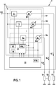
- Fig. 1 shows a schematic block diagram of an embodiment of a security system according to the invention for at least one consumer of a vehicle.
- the illustrated embodiment of a fuse system 1 for at least one consumer V1, V2, Vn of a vehicle comprises a security device 10 which has at least one electronic fuse S1, S2, Sn for the at least one consumer V1, V2, Vn and an evaluation device. and control circuit 12.
- the one evaluation and control circuit 12 evaluates the load current iL1, iL2, iLn through the at least one electronic fuse S1, S2, Sn and compares the load current iL1, iL2, iLn with at least one predetermined switch-off criterion of a first parameter set P1.
- the evaluation and control circuit 12 initiates a tripping process which triggers the at least one electronic fuse S1, S2, Sn and switches off the load current iL1, iL2, iLn to the corresponding consumer V1, V2, Vn when the at least one predefined switch-off criterion has been met .
- an evaluation and control unit 20 additionally evaluates the load current iL1, iL2, iLn through the at least one electronic fuse S1, S2, Sn and compares the load current iL1, iL2, iLn with at least one predefined complex switch-off criterion of a complex parameter set P1K and interrupts it triggering process initiated by the evaluation and control circuit 12 by outputting at least one corresponding control signal to the evaluation and control circuit 12 for a predetermined period of time.
- the evaluation and control circuit 12 terminates the triggering process if the load current iL1, iL2, iLn does not meet the at least one complex switch-off criterion or triggers the at least one electronic fuse S1, S2, Sn and switches the load current iL1, iL2, iLn to the corresponding one Consumers V1, V2, Vn from when the load current iL1, iL2, iLn meets the at least one complex switch-off criterion.
- the evaluation and control circuit 12 monitors a functionality of the evaluation and control unit 20 and, when a faulty function of the evaluation and control unit 20 is detected, switches over to an emergency operation mode in which the evaluation and control circuit 12 controls signals of the evaluation and control unit 20 ignored and evaluates the load current iL1, iL2, iLn through the at least one electronic fuse S1, S2, Sn and compares it with at least one predetermined switch-off criterion of an emergency operation parameter set PNL.
- the evaluation and control circuit 12 triggers the at least one electronic fuse S1, S2, Sn and switches the load current iL1, iL2, iLn to the corresponding consumer V1, V2, Vn if the at least one specified switch-off criterion of the emergency running parameter set PNL is fulfilled.
- the fuse system 1 shown comprises n electronic fuses, of which three electronic fuses S1, S2, Sn are shown as examples, for n consumers, of which three consumers V1, V2, Vn are shown as examples.
- the electronic fuses S1, S2, Sn each comprise at least one semiconductor switch T1, T2, Tn, which supplies the associated consumer V1, V2, Vn with a load current iL1, iL2, iLn in the conductive state and the load current iL1, iL2 in the blocking state.
- iLn switches off, and at least one ammeter A1, A2, An, which detects the load current iL1, iL2, iLn through the at least one semiconductor switch T1, T2, Tn and an associated measurement signal M1, M2, Mn to the evaluation and control circuit 12 and the Outputs evaluation and control unit 20, which represents the detected load current iL1, iL2, iLn.
- the electronic fuses S1, S2, Sn operate bidirectionally and secure the current path to the corresponding consumer V1, V2, Vn in both current directions.
- the semiconductor switches T1, T2, Tn of the electronic fuses S1, S2, Sn can each form a measuring shunt for the corresponding ammeter A1, A2, An.
- a monitoring function 14, which monitors the functionality of the evaluation and control unit 20, can be implemented in the evaluation and control circuit 12, for example, in the manner of a “watchdog function” known from the prior art.
- the evaluation and control circuit 12 is designed as an application-specific integrated circuit ASIC, which has a memory in which the first parameter set P1 and the emergency running parameter set PNL are stored.
- the evaluation and control circuit 12 can also be designed as a discrete electronic circuit.
- the evaluation and control unit 20 is designed as a microcontroller in which the complex parameter set P1K is stored.
- the evaluation and control unit 20 designed as a microcontroller processes program code from software modules in order to carry out complex evaluations of the detected load currents iL1, iL2, iLn.
- the first parameter set P1 of the evaluation and control circuit 12 comprises switch-off criteria which, by means of first switch-off thresholds for the load currents iL1, iL2, iLn, safeguard the load currents iL1, iL2, iLn of the at least one consumer V1, V2, Vn in a time range of less than or equal to 10 ⁇ s implement.
- the emergency operation parameter set PNL of the evaluation and control circuit 12 comprises switch-off criteria, which second switch-off thresholds for the load currents iL1, iL2, iLn, which are higher than the first switch-off thresholds, for at least one prioritized consumer V1, V2, Vn and third switch-off thresholds for the load currents iL1, iL2, iLn, which are lower than the first switch-off thresholds, relate to at least one subordinate consumer V1, V2, Vn.
- the second shutdown thresholds for the load currents iL1, iL2, iLn each correspond to a maximum permissible limit value of the associated prioritized consumer V1, V2, Vn and / or the third shutdown thresholds for the load currents iL1, iL2, iLn lead to the shutdown of the at least one subordinate one Lead consumer V1, V2, Vn.
- a first consumer V1 and a second consumer are prioritized consumers, which are very important for the vehicle function
- an nth consumer Vn is a subordinate consumer, which is not required for the function of the vehicle
- a lower third switch-off threshold is stored in the emergency operation parameter set PNL than the first switch-off threshold in the first parameter set P1.
- the low third shutdown threshold leads to the direct shutdown of the nth consumer Vn.
- the complex parameter set P1K of the evaluation and control unit 20 includes switch-off criteria which, by means of complex evaluation processes, secure the load currents iL1, iL2, iLn and / or the powers and / or energies of the at least one consumer V1, V2, Vn in a time range of greater than 10 ⁇ s implement.
- the complex parameter set P1K of the evaluation and control unit 20 secures profiles for the at least one consumer V1, V2, Vn, which are based on combinations of load currents iL1, iL2, iLn and / or powers and / or energies.
- the hardware of the security system is based on the evaluation and control circuit designed as an ASIC, power electronics in the form of the semiconductor switches and the evaluation and control unit designed as a microcontroller.
- the evaluation and control circuit which is designed as an ASIC, has an analog measuring device which monitors predetermined current threshold values independently of the evaluation and control unit which is designed as a microcontroller. If these current threshold values are exceeded by an overcurrent, the evaluation and control circuit implemented as ASIC initiates the tripping or switch-off process.
- the evaluation and control unit designed as a microcontroller can, however, prevent this switch-off process by rapid intervention for a predetermined period of time.
- the evaluation and control circuit designed as ASIC monitors the evaluation and control unit designed as a microcontroller.
- the evaluation and control unit designed as a microcontroller can prevent the shutdown. However, if the evaluation and control unit designed as a microcontroller failed, the overcurrent would provoke the shutdown. However, if the evaluation and control circuit designed as ASIC has recognized the failure of the evaluation and control unit designed as microcontroller, the evaluation and control circuit designed as ASIC can autonomously access a second set of emergency operation parameters that is specified in advance. In contrast to the first parameter set, this second emergency running parameter set does not have the optimal protection as the first goal but the maximum functional reliability. This can mean that subordinate consumers are switched off immediately in order to be able to provide important consumers with increased energy reserves. In the example above, e.g. the switch-off threshold can be raised to the maximum permissible limit in order to prevent the switch-off by the overcurrent.
Landscapes
- Emergency Protection Circuit Devices (AREA)
- Financial Or Insurance-Related Operations Such As Payment And Settlement (AREA)
- Engineering & Computer Science (AREA)
- Artificial Intelligence (AREA)
- Evolutionary Computation (AREA)
Description
- Die Erfindung geht aus von einem Sicherungssystem für mindestens einen Verbraucher eines Fahrzeugs nach der Gattung des unabhängigen Patentanspruchs 1.
- Aus dem Stand der Technik sind anstelle von Schmelzsicherungen und Relais integrierte Halbleiterbausteine für die Darstellung einer elektronischen Sicherungsfunktion bekannt. Diese umfassen in der Regel einen elektronischen Leistungsschalter zum Ein- und Abschalten einer angeschlossenen elektrischen Last und auch Elemente zur Darstellung von Schutzfunktionen bei Überstrom, Übertemperatur usw. Diese bekannten elektronischen Sicherungen weisen fest vorgegebene Auslöseströme und Auslösezeiten auf. Das bedeutet, dass die elektronische Sicherung in einem festen Betriebspunkt arbeitet und die Überstromabschaltung bereits an einem ersten unteren Schwellwert erfolgt, der nicht zu einer Schädigung des Halbleiterschalters führt.
- Des Weiteren kann bei den bekannten elektronischen Sicherungen ein erhöhter Anlaufstrom ("Inrush Current"), welcher beispielsweise durch Vorladung eines Kondensators einer angeschlossenen elektrischen Lastimpedanz oder durch ein Losbrechmoment eines Elektromotors verursacht werden kann, zu einer Überstromerkennung und einer fälschlichen Auslösung der elektronischen Sicherung führen, obwohl die Stromhöhe noch keine kritische Schwelle erreicht hat, bei welcher mit einer Schädigung der Halbleiterschalter zu rechnen ist.
- Zudem werden derartige Sicherungssysteme zunehmend "intelligenter", d.h. mit Mikrocontrollern ausgestattet, welche sich den veränderlichen Rahmenbedingungen anpassen können, um zusätzliche Aufgaben, wie beispielsweise Strommessung und Überwachung, übernehmen und/oder zusätzliche physikalische Anforderungen, wie beispielsweise Lichtbögen bei Systemen mit höheren Versorgungsspannung von über 24V, erfüllen zu können. Ein solcher Mikrocontroller erlaubt es auch, den Sicherungsbereich möglichst schmal zu halten, d.h. ein Überstromereignis wird sehr früh identifiziert und abgeschaltet.
- Aus der
DE102008012605A1 sind bereits ein Schutzschaltgerät zum Überwachen des elektrischen Stromflusses zu einem elektrischen Verbraucher bzw. Verfahren zur Überwachung des elektrischen Stromflusses zu einem elektrischen Verbraucher durch ein Schutzschaltgerät bekannt. Weitere gattungsgemäße Vorrichtungen sind in derEP2498359A1 bzw.US014/0226248A1 gezeigt. - Das Sicherungssystem für mindestens einen Verbraucher eines Fahrzeugs mit den Merkmalen des unabhängigen Patentanspruchs 1 hat den Vorteil, dass eine Auswerte- und Steuereinheit komplexere Auswertungen des erfassten Laststroms vorzugsweise unter Verwendung von Softwaremodulen bzw. Programmcode für den mindestens einen Verbraucher übernimmt, deren Ausführung im ein- oder mehrstelligen Mikrosekundenbereich erledigt werden kann. Die Auswerte- und Steuerschaltung reagiert im Falle eines so genannten harten (=niederohmigen) Kurzschlusses jedoch erheblich schneller und ist in der Lage, Auslöseentscheidungen auch ohne Beteiligung der Auswerte- und Steuereinheit treffen zu können. Ausführungsformen des erfindungsgemäßen Sicherungssystems können den Laststrom im Falle eines harten Kurzschlusses schnell abschalten und trotzdem eine verfrühte bzw. fehlerhafte Abschaltung des Laststroms vermeiden, bei welcher der Laststrom abgeschaltet wird, obwohl kein ausreichender Überstrom vorhanden ist. Da die ursprünglich vorgegebenen Abschaltkriterien des ersten Parametersatzes bei Ausfall der Auswerte- und Steuereinheit sehr schnell zu einer fehlerhaften bzw. verfrühten Abschaltung des Laststroms führen können, da die Auswerte- und Steuereinheit nicht mehr korrektiv eingreifen kann, überwacht die Auswerte- und Steuerschaltung die Funktion der Auswerte- und Steuereinheit und schaltet bei Ausfall in einen Notlaufbetrieb um. Im Notlaufbetrieb kann die Auswerte- und Steuerschaltung durch die Verwendung eines Notlaufparametersatzes die Funktionsfähigkeit des Sicherungssystems auch bei Ausfall der Auswerte- und Steuereinheit in vorteilhafter Weise aufrechterhalten. Dieser Notlaufbetrieb unterscheidet sich dadurch signifikant vom Normalbetrieb, dass jetzt nicht mehr alle Verbraucher, Zuleitungen usw. optimal geschützt werden, sondern das relevante Verbraucher beispielsweise mit maximal zulässigen Abschaltschwellwerten abgesichert werden. Das bedeutet, dass Ausführungsformen des erfindungsgemäßen Sicherungssystems im Notfallbetrieb keine redundanten Absicherungsfunktionen, sondern Absicherungsfunktionen mit einer erhöhten Fehlertoleranz und geändertem Absicherungsziel zur Verfügung stellen. Dadurch können Ausführungsformen ein fehlertolerantes Sicherungssystem zur Verfügung stellten, welches Hardwarekomponenten und Softwarekomponenten umfasst.
- Ausführungsformen der vorliegenden Erfindung stellen ein Sicherungssystem für mindestens einen Verbraucher eines Fahrzeugs zur Verfügung, welches eine Sicherungsvorrichtung mit mindestens einer elektronischen Sicherung für den mindestens einen Verbraucher und einer Auswerte- und Steuerschaltung umfasst. Die Auswerte- und Steuerschaltung wertet den Laststrom durch die mindestens eine elektronische Sicherung aus und vergleicht den Laststrom mit mindestens einem vorgegebenen Abschaltkriterium eines ersten Parametersatzes. Die Auswerte- und Steuerschaltung leitet einen Auslöseprozess ein, welcher die mindestens eine elektronische Sicherung auslöst und den Laststrom zum korrespondierenden Verbraucher abschaltet, wenn das mindestens eine vorgegebene Abschaltkriterium erfüllt ist. Hierbei wertet eine Auswerte- und Steuereinheit den Laststrom durch die mindestens eine elektronische Sicherung zusätzlich aus und vergleicht den Laststrom mit mindestens einem vorgegebenen komplexen Abschaltkriterium eines komplexen Parametersatzes und unterbricht den von der Auswerte- und Steuerschaltung eingeleiteten Auslöseprozess durch Ausgabe mindestens eines korrespondierenden Steuersignals an die Auswerte- und Steuerschaltung für eine vorbestimmte Zeitspanne. Die Auswerte- und Steuerschaltung bricht den Auslöseprozess ab, wenn der Laststrom das mindestens eine komplexe Abschaltkriterium nicht erfüllt oder löst die mindestens eine elektronische Sicherung aus und schaltet den Laststrom zum korrespondierenden Verbraucher ab, wenn der Laststrom das mindestens eine komplexe Abschaltkriterium erfüllt. Zudem überwacht die Auswerte- und Steuerschaltung eine Funktionalität der Auswerte- und Steuereinheit und schaltet bei einer erkannten fehlerhaften Funktion der Auswerte- und Steuereinheit in einen Notlaufbetrieb um, in welchem die Auswerte- und Steuerschaltung Steuersignale der Auswerte- und Steuereinheit ignoriert und den Laststrom durch die mindestens eine elektronische Sicherung auswertet und mit mindestens einem vorgegebenen Abschaltkriterium eines Notlaufparametersatzes vergleicht. Die Auswerte- und Steuerschaltung löst die mindestens eine elektronische Sicherung aus und schaltet den Laststrom zum korrespondierenden Verbraucher ab, wenn das mindestens eine vorgegebene Abschaltkriterium des Notlaufparametersatzes erfüllt ist.
- Unter der Auswerte- und Steuereinheit kann vorliegend ein elektrisches Gerät, wie beispielsweise ein Steuergerät, insbesondere ein Bordnetzsteuergerät, verstanden werden, welches erfasste Sensor- und/oder Messsignale verarbeitet bzw. auswertet. Die Auswerte- und Steuereinheit kann mindestens eine Schnittstelle aufweisen, die hard- und/oder softwaremäßig ausgebildet sein kann. Bei einer hardwaremäßigen Ausbildung können die Schnittstellen beispielsweise Teil eines sogenannten System-ASICs sein, der verschiedenste Funktionen der Auswerte- und Steuereinheit beinhaltet. Es ist jedoch auch möglich, dass die Schnittstellen eigene, integrierte Schaltkreise sind oder zumindest teilweise aus diskreten Bauelementen bestehen. Bei einer softwaremäßigen Ausbildung können die Schnittstellen Softwaremodule sein, die beispielsweise auf einem Mikrocontroller neben anderen Softwaremodulen vorhanden sind. Von Vorteil ist auch ein Computerprogrammprodukt mit Programmcode, der auf einem maschinenlesbaren Träger wie einem Halbleiterspeicher, einem Festplattenspeicher oder einem optischen Speicher gespeichert ist und zur Durchführung der Auswertung verwendet wird, wenn das Programm von der Auswerte- und Steuereinheit ausgeführt wird.
- Durch die in den abhängigen Ansprüchen aufgeführten Maßnahmen und Weiterbildungen sind vorteilhafte Verbesserungen des im unabhängigen Patentanspruch 1 angegebenen Sicherungssystems für mindestens einen Verbraucher eines Fahrzeugs möglich.
- Besonders vorteilhaft ist, dass die Auswerte- und Steuerschaltung als anwendungsspezifische integrierte Schaltung (ASIC) und/oder als diskrete elektronische Schaltung und die Auswerte- und Steuereinheit als Mikrocontroller ausgeführt werden können. Dadurch können die autonomen Hardwarekomponenten des fehlertoleranten Sicherungssystems einfach als ASIC bzw. diskrete elektronische Schaltung und die Softwarekomponente durch den Mikrocontroller realisiert werden.
- In vorteilhafter Ausgestaltung des erfindungsgemäßen Sicherungssystems kann der erste Parametersatz der Auswerte- und Steuerschaltung Abschaltkriterien umfassen, welche durch erste Abschaltschwellen für die Lastströme eine Absicherung der Lastströme des mindestens einen Verbrauchers in einem Zeitbereich von kleiner gleich 10µs umsetzen. Zudem kann der Notlaufparametersatz der Auswerte- und Steuerschaltung Abschaltkriterien umfassen, welche zweite Abschaltschwellen für die Lastströme, welche höher als die ersten Abschaltschwellen sein können, für mindestens einen priorisierten Verbraucher und dritte Abschaltschwellen für die Lastströme, welche niedriger als die ersten Abschaltschwellen sein können, für mindestens einen nachrangigen Verbraucher betreffen können. So können die zweiten Abschaltschwellen für die Lastströme jeweils einem maximal zulässigen Grenzwert des zugehörigen priorisierten Verbrauchers entsprechen und/oder die dritten Abschaltschwellen für die Lastströme können zum Abschalten des mindestens einen nachrangigen Verbrauchers führen. Des Weiteren kann der komplexe Parametersatz der Auswerte- und Steuereinheit Abschaltkriterien umfassen, welche durch komplexe Auswertevorgänge eine Absicherung der Lastströme und/oder Leistungen und/oder Energien des mindestens einen Verbrauchers in einem Zeitbereich von größer als 10µs umsetzen können. Der komplexe Parametersatz der Auswerte- und Steuereinheit kann beispielsweise Profile für den mindestens einen Verbraucher absichern, welche auf Kombinationen von Lastströmen und/oder Leistungen und/oder Energien basieren. Somit übernimmt die Auswerte- und Steuerschaltung die Ansteuer- und Versorgungsaufgaben sowie die Bereitstellung der vorprogrammierten Abschaltschwellen. Ein intelligentes Sicherungssystem sichert jedoch nicht nur Lastströme, sondern auch Leistungen- und/oder Energien ab. Dies alles, wie auch die Verhinderung von Fehlabschaltungen durch erhöhte Anlaufströme "Inrush-Currents", übernimmt die Auswerte- und Steuereinheit. Die Absicherung durch die Auswerte- und Steuerschaltung erfolgt parallel zu der Absicherung durch die Auswerte- und Steuereinheit permanent im Hintergrund. Während die Auswerte- und Steuerschaltung damit auf reine Stromschwellen im unteren Zeitbereich kleiner, gleich 10µs absichert, sichert die Auswerte- und Steuereinheit durch komplexe Auswertevorgänge komplexe Abschaltkriterien, wie beispielsweise Kombinationen aus Lastströmen, Leistungen, Energien oder darauf basierender Profile ab. Dies erfolgt jedoch in der Regel für höhere Zeitbereiche größer als 10µs, vorzugsweise größer als 100us. Im Notlaufbetrieb fällt die Absicherung durch die Auswerte- und Steuereinheit vollständig weg.
- In weiterer vorteilhafter Ausgestaltung des erfindungsgemäßen Sicherungssystems kann die mindestens eine elektronische Sicherung bidirektional arbeiten und den Strompfad zum korrespondierenden Verbraucher in beide Stromrichtungen absichern.
- In weiterer vorteilhafter Ausgestaltung des erfindungsgemäßen Sicherungssystems kann die mindestens eine elektronische Sicherung mindestens einen Halbleiterschalter, welcher im leitenden Zustand den zugehörigen Verbraucher mit einem Laststrom versorgen und im sperrenden Zustand den Laststrom abschalten kann, und mindestens einen Strommesser umfassen, welcher den Laststrom durch den mindestens einen Halbleiterschalter erfassen und ein zugehöriges Messsignal an die Auswerte- und Steuerschaltung und die Auswerte- und Steuereinheit ausgeben kann, welches den erfassten Laststrom repräsentieren kann. Dies ermöglicht einen einfachen kostengünstigen Aufbau der elektronischen Sicherung mit handelsüblichen Bauteilen.
- In weiterer vorteilhafter Ausgestaltung des erfindungsgemäßen Sicherungssystems kann der mindestens eine Halbleiterschalter einen Messshunt für den korrespondierenden Strommesser ausbildet. Dadurch kann in vorteilhafter Weise Layout-Fläche und Bauraum eingespart werden.
- Ein Ausführungsbeispiel der Erfindung ist in der Zeichnung dargestellt und wird in der nachfolgenden Beschreibung näher erläutert. In der Zeichnung bezeichnen gleiche Bezugszeichen Komponenten bzw. Elemente, die gleiche bzw. analoge Funktionen ausführen.
-
Fig. 1 zeigt ein schematisches Blockdiagramm eines Ausführungsbeispiels eines erfindungsgemäßen Sicherungssystems für mindestens einen Verbraucher eines Fahrzeugs. - Wie aus
Fig. 1 ersichtlich ist, umfasst das dargestellte Ausführungsbeispiel eines erfindungsgemäßen Sicherungssystem 1 für mindestens einen Verbraucher V1, V2, Vn eines Fahrzeugs eine Sicherungsvorrichtung 10, welche mindestens eine elektronische Sicherung S1, S2, Sn für den mindestens einen Verbraucher V1, V2, Vn und eine Auswerte- und Steuerschaltung 12 umfasst. Die eine Auswerte- und Steuerschaltung 12 wertet den Laststrom iL1, iL2, iLn durch die mindestens eine elektronische Sicherung S1, S2, Sn aus und vergleicht den Laststrom iL1, iL2, iLn mit mindestens einem vorgegebenen Abschaltkriterium eines ersten Parametersatzes P1. Hierbei leitet die Auswerte- und Steuerschaltung 12 einen Auslöseprozess ein, welcher die mindestens eine elektronische Sicherung S1, S2, Sn auslöst und den Laststrom iL1, iL2, iLn zum korrespondierenden Verbraucher V1, V2, Vn abschaltet, wenn das mindestens eine vorgegebene Abschaltkriterium erfüllt ist. Zudem wertet eine Auswerte- und Steuereinheit 20 den Laststrom iL1, iL2, iLn durch die mindestens eine elektronische Sicherung S1, S2, Sn zusätzlich aus und vergleicht den Laststrom iL1, iL2, iLn mit mindestens einem vorgegebenen komplexen Abschaltkriterium eines komplexen Parametersatzes P1K und unterbricht den von der Auswerte- und Steuerschaltung 12 eingeleiteten Auslöseprozess durch Ausgabe mindestens eines korrespondierenden Steuersignals an die Auswerte- und Steuerschaltung 12 für eine vorbestimmte Zeitspanne. Die Auswerte- und Steuerschaltung 12 bricht den Auslöseprozess ab, wenn der Laststrom iL1, iL2, iLn das mindestens eine komplexe Abschaltkriterium nicht erfüllt oder löst die mindestens eine elektronische Sicherung S1, S2, Sn aus und schaltet den Laststrom iL1, iL2, iLn zum korrespondierenden Verbraucher V1, V2, Vn ab, wenn der Laststrom iL1, iL2, iLn das mindestens eine komplexe Abschaltkriterium erfüllt. Des Weiteren überwacht die Auswerte- und Steuerschaltung 12 eine Funktionalität der Auswerte- und Steuereinheit 20 und schaltet bei einer erkannten fehlerhaften Funktion der Auswerte- und Steuereinheit 20 in einen Notlaufbetrieb um, in welchem die Auswerte- und Steuerschaltung 12 Steuersignale der Auswerte- und Steuereinheit 20 ignoriert und den Laststrom iL1, iL2, iLn durch die mindestens eine elektronische Sicherung S1, S2, Sn auswertet und mit mindestens einem vorgegebenen Abschaltkriterium eines Notlaufparametersatzes PNL vergleicht. Im Notlaufbetrieb löst die Auswerte- und Steuerschaltung 12 die mindestens eine elektronische Sicherung S1, S2, Sn aus und schaltet den Laststrom iL1, iL2, iLn zum korrespondierenden Verbraucher V1, V2, Vn ab, wenn das mindestens eine vorgegebene Abschaltkriterium des Notlaufparametersatzes PNL erfüllt ist. - Wie aus
Fig. 1 weiter ersichtlich ist, umfasst das dargestellte Sicherungssystem 1 n elektronische Sicherungen, von welchen beispielhaft jeweils drei elektronische Sicherungen S1, S2, Sn dargestellt sind, für n Verbraucher, von denen beispielhaft drei Verbraucher V1, V2, Vn dargestellt sind. Die elektronischen Sicherungen S1, S2, Sn umfassen jeweils mindestens einen Halbleiterschalter T1, T2, Tn, welcher im leitenden Zustand den zugehörigen Verbraucher V1, V2, Vn mit einem Laststrom iL1, iL2, iLn versorgt und im sperrenden Zustand den Laststrom iL1, iL2, iLn abschaltet, und mindestens einen Strommesser A1, A2, An, welcher den Laststrom iL1, iL2, iLn durch den mindestens einen Halbleiterschalter T1, T2, Tn erfasst und ein zugehöriges Messsignal M1, M2, Mn an die Auswerte- und Steuerschaltung 12 und die Auswerte- und Steuereinheit 20 ausgibt, welches den erfassten Laststrom iL1, iL2, iLn repräsentiert. Die elektronischen Sicherungen S1, S2, Sn arbeiten bidirektional und sichern den Strompfad zum korrespondierenden Verbraucher V1, V2, Vn in beide Stromrichtungen ab. Bei einem nicht dargestellten Ausführungsbeispiel können die Halbleiterschalter T1, T2, Tn der elektronischen Sicherungen S1, S2, Sn jeweils einen Messshunt für den korrespondierenden Strommesser A1, A2, An ausbilden. Eine Überwachungsfunktion 14, welche die Funktionalität der Auswerte- und Steuereinheit 20 überwacht, kann beispielsweise in Art einer aus dem Stand der Technik bekannten "Watchdog-Funktion" in der Auswerte- und Steuerschaltung 12 implementiert werden. - Im dargestellten Ausführungsbeispiel ist die Auswerte- und Steuerschaltung 12 als anwendungsspezifische integrierte Schaltung ASIC ausgeführt, welche einen Speicher aufweist in welchem der erste Parametersatz P1 und der Notlaufparametersatz PNL gespeichert sind. Selbstverständlich kann die Auswerte- und Steuerschaltung 12 auch als diskrete elektronische Schaltung ausgeführt werden. Die Auswerte- und Steuereinheit 20 ist als Mikrocontroller ausgeführt, in welchem der komplexe Parametersatz P1K gespeichert ist. Die als Mikrocontroller ausgeführte Auswerte- und Steuereinheit 20 arbeitet Programmcode von Softwaremodulen ab, um komplexe Auswertungen der erfassten Lastströme iL1, iL2, iLn vorzunehmen.
- Der erste Parametersatz P1 der Auswerte- und Steuerschaltung 12 umfasst Abschaltkriterien, welche durch erste Abschaltschwellen für die Lastströme iL1, iL2, iLn eine Absicherung der Lastströme iL1, iL2, iLn des mindestens einen Verbrauchers V1, V2, Vn in einem Zeitbereich von kleiner gleich 10µs umsetzen. Der Notlaufparametersatz PNL der Auswerte- und Steuerschaltung 12 umfasst Abschaltkriterien, welche zweite Abschaltschwellen für die Lastströme iL1, iL2, iLn, welche höher als die ersten Abschaltschwellen sind, für mindestens einen priorisierten Verbraucher V1, V2, Vn und dritte Abschaltschwellen für die Lastströme iL1, iL2, iLn, welche niedriger als die ersten Abschaltschwellen sind, für mindestens einen nachrangigen Verbraucher V1, V2, Vn betreffen. Im dargestellten Ausführungsbeispiel entsprechen die zweiten Abschaltschwellen für die Lastströme iL1, iL2, iLn jeweils einem maximal zulässigen Grenzwert des zugehörigen priorisierten Verbrauchers V1, V2, Vn und/oder die dritten Abschaltschwellen für die Lastströme iL1, iL2, iLn führen zum Abschalten des mindestens einen nachrangigen Verbrauchers V1, V2, Vn führen. Unter der Annahme, dass ein erster Verbraucher V1 und ein zweiter Verbraucher priorisierte Verbraucher sind, welche für den Fahrzeugfunktion sehr wichtig sind, und ein n-ter Verbraucher Vn ein nachgeordneter Verbraucher ist, der für die Funktion des Fahrzeugs nicht erforderlich ist, sind im Notlaufparametersatz PNL höhere zweite Abschaltschwellen für die Lastströme iL1, iL2 des ersten und zweiten Verbrauchers V1, V2 gespeichert als die ersten Abschaltschwellen im ersten Parametersatz P1. Für den Laststrom iLn durch den n-ten Verbraucher Vn ist eine niedriger dritte Abschaltschwelle im Notlaufparametersatz PNL gespeichert als die erste Abschaltschwelle im ersten Parametersatz P1. Im Extremfall führt die niedrige dritte Abschaltschwelle zur direkten Abschaltung des n-ten Verbrauchers Vn.
- Der komplexe Parametersatz P1K der Auswerte- und Steuereinheit 20 umfasst Abschaltkriterien, welche durch komplexe Auswertevorgänge eine Absicherung der Lastströme iL1, iL2, iLn und/oder Leistungen und/oder Energien des mindestens einen Verbrauchers V1, V2, Vn in einem Zeitbereich von größer als 10µs umsetzen. So sichert im dargestellten Ausführungsbeispiel der komplexe Parametersatz P1K der Auswerte- und Steuereinheit 20 Profile für den mindestens einen Verbraucher V1, V2, Vn ab, welche auf Kombinationen von Lastströmen iL1, iL2, iLn und/oder Leistungen und/oder Energien basieren.
- In Ausführungsformen der vorliegenden Erfindung basiert die Hardware des Sicherungssystems auf der als ASIC ausgeführten Auswerte- und Steuerschaltung, einer Leistungselektronik in Form der Halbleiterschalter und der als Mikrocontroller ausgeführten Auswerte- und Steuereinheit. Die als ASIC ausgeführte Auswerte- und Steuerschaltung verfügt über eine analoge Messeinrichtung, welche unabhängig von der beteiligten als Mikrocontroller ausgeführten Auswerte- und Steuereinheit vorgegebene Stromschwellwerte überwacht. Werden diese Stromschwellwerte durch einen Überstrom überschritten, leitet die als ASIC ausgeführte Auswerte- und Steuerschaltung den Auslöse- bzw. Abschaltprozess ein. Die als Mikrocontroller ausgeführte Auswerte- und Steuereinheit kann diesen Abschaltprozess jedoch durch schnellen Eingriff für eine vorbestimmte Zeitdauer verhindern. Parallel dazu überwacht die als ASIC ausgeführte Auswerte- und Steuerschaltung die als Mikrocontroller ausgeführte Auswerte- und Steuereinheit. Insofern die als Mikrocontroller ausgeführte Auswerte- und Steuereinheit weiter aktiv ist, kann die Auswerte- und Steuereinheit die Abschaltung verhindern. Ist die als Mikrocontroller ausgeführte Auswerte- und Steuereinheit jedoch ausgefallen, würde hier der Überstrom die Abschaltung provozieren. Wenn die als ASIC ausgeführte Auswerte- und Steuerschaltung den Ausfall der als Mikrocontroller ausgeführten Auswerte- und Steuereinheit jedoch erkannt hat, kann die als ASIC ausgeführte Auswerte- und Steuerschaltung autonom auf einen zweiten, im Vorfeld vorgegebenen Notlaufparametersatz zugreifen. Dieser zweite Notlaufparametersatz hat aber im Gegenteil zum ersten Parametersatz nicht die optimale Absicherung als erstes Ziel sondern die maximale Funktionssicherheit. Das kann beinhalten, dass nachrangige Verbraucher sofort abgeschaltet werden, um wichtigen Verbrauchern erhöhte Energiereserven zur Verfügung stellen zu können. In obigem Beispiel könnte z.B. die Abschaltschwelle auf die höchstzulässige Grenze angehoben werden, um der Abschaltung durch den Überstrom vorzubeugen.
Claims (10)
- Sicherungssystem (1) für mindestens einen Verbraucher (V1, V2, Vn) eines Fahrzeugs, mit einer Sicherungsvorrichtung (10), welche mindestens eine elektronische Sicherung (S1, S2, Sn) für den mindestens einen Verbraucher (V1, V2, Vn) und eine Auswerte- und Steuerschaltung (12) umfasst, welche den Laststrom (iL1, iL2, iLn) durch die mindestens eine elektronische Sicherung (S1, S2, Sn) auswertet und mit mindestens einem vorgegebenen Abschaltkriterium eines ersten Parametersatzes (P1) vergleicht, wobei die Auswerte- und Steuerschaltung (12) einen Auslöseprozess einleitet, welcher die mindestens eine elektronische Sicherung (S1, S2, Sn) auslöst und den Laststrom (iLl, iL2, iLn) zum korrespondierenden Verbraucher (V1, V2, Vn) abschaltet, wenn das mindestens eine vorgegebene Abschaltkriterium erfüllt ist, dadurch gekennzeichnet, dass eine Auswerte- und Steuereinheit (20) den Laststrom (iLl, iL2, iLn) durch die mindestens eine elektronische Sicherung (S1, S2, Sn) zusätzlich auswertet und mit mindestens einem vorgegebenen komplexen Abschaltkriterium eines komplexen Parametersatzes (P1K) vergleicht und den von der Auswerte- und Steuerschaltung (12) eingeleiteten Auslöseprozess durch Ausgabe mindestens eines korrespondierenden Steuersignals an die Auswerte- und Steuerschaltung (12) für eine vorbestimmte Zeitspanne unterbricht, wobei die Auswerte- und Steuerschaltung (12) den Auslöseprozess abbricht, wenn der Laststrom (iLl, iL2, iLn) das mindestens eine komplexe Abschaltkriterium nicht erfüllt oder die mindestens eine elektronische Sicherung (S1, S2, Sn) auslöst und den Laststrom (iLl, iL2, iLn) zum korrespondierenden Verbraucher (V1, V2, Vn) abschaltet, wenn der Laststrom (iLl, iL2, iLn) das mindestens eine komplexe Abschaltkriterium erfüllt, wobei die Auswerte- und Steuerschaltung (12) eine Funktionalität der Auswerte- und Steuereinheit (20) überwacht und bei einer erkannten fehlerhaften Funktion der Auswerte- und Steuereinheit (20) in einen Notlaufbetrieb umschaltet, in welchem die Auswerte- und Steuerschaltung (12) Steuersignale der Auswerte- und Steuereinheit (20) ignoriert und den Laststrom (iL1, iL2, iLn) durch die mindestens eine elektronische Sicherung (S1, S2, Sn) auswertet und mit mindestens einem vorgegebenen Abschaltkriterium eines Notlaufparametersatzes (PNL) vergleicht, wobei die Auswerte- und Steuerschaltung (12) die mindestens eine elektronische Sicherung (S1, S2, Sn) auslöst und den Laststrom (iLl, iL2, iLn) zum korrespondierenden Verbraucher (V1, V2, Vn) abschaltet, wenn das mindestens eine vorgegebene Abschaltkriterium des Notlaufparametersatzes (PNL) erfüllt ist.
- Sicherungssystem nach Anspruch 1, dadurch gekennzeichnet, dass die Auswerte- und Steuerschaltung (12) als anwendungsspezifische integrierte Schaltung (ASIC) und/oder als diskrete elektronische Schaltung und die Auswerte- und Steuereinheit (20) als Mikrocontroller ausgeführt ist.
- Sicherungssystem nach Anspruch 1 oder 2, dadurch gekennzeichnet, dass ausgeführt ist der erste Parametersatz (P1) der Auswerte- und Steuerschaltung (12) Abschaltkriterien umfasst, welche durch erste Abschaltschwellen für die Lastströme (iLl, iL2, iLn) eine Absicherung der Lastströme (iLl, iL2, iLn) des mindestens einen Verbrauchers (V1, V2, Vn) in einem Zeitbereich von kleiner gleich 10µs umsetzen.
- Sicherungssystem nach Anspruch 3, dadurch gekennzeichnet, dass der Notlaufparametersatz (PNL) der Auswerte- und Steuerschaltung (12) Abschaltkriterien umfasst, welche zweite Abschaltschwellen für die Lastströme (iLl, iL2, iLn), welche höher als die ersten Abschaltschwellen sind, für mindestens einen priorisierten Verbraucher (V1, V2, Vn) und dritte Abschaltschwellen für die Lastströme (iLl, iL2, iLn), welche niedriger als die ersten Abschaltschwellen sind, für mindestens einen nachrangigen Verbraucher (V1, V2, Vn) betreffen.
- Sicherungssystem nach Anspruch 4, dadurch gekennzeichnet, dass die zweiten Abschaltschwellen für die Lastströme (iLl, iL2, iLn) jeweils einem maximal zulässigen Grenzwert des zugehörigen priorisierten Verbrauchers (V1, V2, Vn) entsprechen und/oder die dritten Abschaltschwellen für die Lastströme (iLl, iL2, iLn) zum Abschalten des mindestens einen nachrangigen Verbrauchers (V1, V2, Vn) führen.
- Sicherungssystem nach einem der Ansprüche 1 bis 5, dadurch gekennzeichnet, dass der komplexe Parametersatz (P1K) der Auswerte- und Steuereinheit (20) Abschaltkriterien umfasst, welche durch komplexe Auswertevorgänge eine Absicherung der Lastströme (iLl, iL2, iLn) und/oder Leistungen und/oder Energien des mindestens einen Verbrauchers (V1, V2, Vn) in einem Zeitbereich von größer als 10µs umsetzen.
- Sicherungssystem nach Anspruch 6, dadurch gekennzeichnet, dass der komplexe Parametersatz (P1K) der Auswerte- und Steuereinheit (20) Profile für den mindestens einen Verbraucher (V1, V2, Vn) absichert, welche auf Kombinationen von Lastströmen (iLl, iL2, iLn) und/oder Leistungen und/oder Energien basieren.
- Sicherungssystem nach einem der Ansprüche 1 bis 7, dadurch gekennzeichnet, dass die mindestens eine elektronische Sicherung (S1, S2, Sn) bidirektional arbeitet und den Strompfad zum korrespondierenden Verbraucher (V1, V2, Vn) in beide Stromrichtungen absichert.
- Sicherungssystem nach einem der Ansprüche 1 bis 8, dadurch gekennzeichnet, dass die mindestens eine elektronische Sicherung (S1, S2, Sn) mindestens einen Halbleiterschalter (T1, T2, Tn), welcher im leitenden Zustand den zugehörigen Verbraucher (V1, V2, Vn) mit einem Laststrom (iLl, iL2, iLn) versorgt und im sperrenden Zustand den Laststrom (iLl, iL2, iLn) abschaltet, und mindestens einen Strommesser (A1, A2, An) umfasst, welcher den Laststrom (iLl, iL2, iLn) durch den mindestens einen Halbleiterschalter (T1, T2, Tn) erfasst und ein zugehöriges Messsignal (M1, M2, Mn) an die Auswerte- und Steuerschaltung (12) und die Auswerte- und Steuereinheit (20) ausgibt, welches den erfassten Laststrom (iLl, iL2, iLn) repräsentiert.
- Sicherungssystem nach Anspruch 9, dadurch gekennzeichnet, dass der mindestens eine Halbleiterschalter (T1, T2, Tn) einen Messshunt für den korrespondierenden Strommesser (A1, A2, An) ausbildet.
Applications Claiming Priority (2)
| Application Number | Priority Date | Filing Date | Title |
|---|---|---|---|
| DE102016207020.7A DE102016207020A1 (de) | 2016-04-26 | 2016-04-26 | Sicherungssystem für mindestens einen Verbraucher eines Fahrzeugs |
| PCT/EP2017/058413 WO2017186475A1 (de) | 2016-04-26 | 2017-04-07 | Sicherungssystem für mindestens einen verbraucher eines fahrzeugs |
Publications (2)
| Publication Number | Publication Date |
|---|---|
| EP3449541A1 EP3449541A1 (de) | 2019-03-06 |
| EP3449541B1 true EP3449541B1 (de) | 2020-06-10 |
Family
ID=58503626
Family Applications (1)
| Application Number | Title | Priority Date | Filing Date |
|---|---|---|---|
| EP17716221.1A Active EP3449541B1 (de) | 2016-04-26 | 2017-04-07 | Sicherungssystem für mindestens einen verbraucher eines fahrzeugs |
Country Status (6)
| Country | Link |
|---|---|
| US (1) | US10923902B2 (de) |
| EP (1) | EP3449541B1 (de) |
| JP (1) | JP6629463B2 (de) |
| CN (1) | CN109075553B (de) |
| DE (1) | DE102016207020A1 (de) |
| WO (1) | WO2017186475A1 (de) |
Families Citing this family (11)
| Publication number | Priority date | Publication date | Assignee | Title |
|---|---|---|---|---|
| DE102016210058A1 (de) * | 2016-06-08 | 2017-12-14 | Robert Bosch Gmbh | Stromverteiler und Sicherungssystem für ein Fahrzeug |
| DE102019120567A1 (de) * | 2019-07-30 | 2021-02-04 | Bayerische Motoren Werke Aktiengesellschaft | Fahrzeug-Bordnetz und Verfahren zum Schutz eines Fahrzeug-Bordnetzes |
| US11646566B2 (en) | 2020-12-16 | 2023-05-09 | Lear Corporation | Apparatus for permanent supply with a switch |
| ES2959012T3 (es) * | 2021-03-25 | 2024-02-19 | Future Systems Besitz Gmbh | Método y aparato para la detección de un fallo de fusible |
| DE102021113107A1 (de) * | 2021-05-20 | 2022-11-24 | Lisa Dräxlmaier GmbH | Elektronischer Sicherungsschaltkreis |
| US12088183B2 (en) | 2021-10-19 | 2024-09-10 | Lear Corporation | Electrical system |
| US11811212B2 (en) * | 2022-03-04 | 2023-11-07 | GM Global Technology Operations LLC | Synchronization of electronic fuses in vehicle power distribution |
| CN114552524B (zh) * | 2022-03-09 | 2023-08-22 | 中铁十五局集团有限公司 | 一种车载复合电源用高压配电单元及其控制方法 |
| CN116027103B (zh) * | 2023-03-29 | 2023-09-15 | 荣耀终端有限公司 | 功耗检测电路、功耗检测芯片及终端设备 |
| DE102024203476A1 (de) * | 2024-04-15 | 2025-10-16 | Conti Temic Microelectronic Gmbh | Schaltungsanordnung zur Steuerung einer elektronischen Sicherung und Verfahren zum Betreiben einer solchen Schaltungsanordnung |
| CN119502704B (zh) * | 2024-11-14 | 2025-09-26 | 一汽解放汽车有限公司 | 新能源汽车高压系统及具其的车辆 |
Family Cites Families (16)
| Publication number | Priority date | Publication date | Assignee | Title |
|---|---|---|---|---|
| JP4419270B2 (ja) * | 2000-04-20 | 2010-02-24 | 株式会社デンソー | 電気負荷駆動用ic |
| JP2001309546A (ja) * | 2000-04-27 | 2001-11-02 | Mitsubishi Cable Ind Ltd | 車両用配線系統の保護装置 |
| JP4171449B2 (ja) * | 2004-06-30 | 2008-10-22 | 三洋電機株式会社 | 車両用の電源装置 |
| US8570699B2 (en) * | 2005-04-22 | 2013-10-29 | Lear Corporation | Relayless and fuseless junction box |
| DE102008012605B4 (de) * | 2008-03-05 | 2013-01-31 | Siemens Aktiengesellschaft | Schutzschaltgerät zum Überwachen des elektrischen Stromflusses zu einem elektrischen Verbrauch |
| JP5489742B2 (ja) * | 2010-01-22 | 2014-05-14 | 三菱電機株式会社 | 保護継電器 |
| JP5494255B2 (ja) * | 2010-06-07 | 2014-05-14 | 富士電機株式会社 | 安全制御システム |
| US8553376B2 (en) * | 2010-12-11 | 2013-10-08 | The Boeing Company | Synchronous rectified PWM regulator with auto fault clearing |
| FR2968855B1 (fr) * | 2010-12-14 | 2012-12-07 | Schneider Electric Ind Sas | Procede et dispositif de surveillance d'un dispositif equipe d'un microprocesseur |
| US20120226453A1 (en) * | 2011-03-02 | 2012-09-06 | General Electric Company | Circuit breaker trip unit |
| US9214797B2 (en) * | 2013-02-13 | 2015-12-15 | General Electric Company | Apparatus, systems, and methods for operation of a trip unit in a circuit protection device |
| JP6052114B2 (ja) * | 2013-09-11 | 2016-12-27 | 株式会社デンソー | 駆動力制御装置 |
| US10391957B2 (en) * | 2016-04-05 | 2019-08-27 | Ford Global Technologies, Llc | Integrated power distribution system for a vehicle |
| DE102016210058A1 (de) * | 2016-06-08 | 2017-12-14 | Robert Bosch Gmbh | Stromverteiler und Sicherungssystem für ein Fahrzeug |
| CN106849001A (zh) * | 2017-04-18 | 2017-06-13 | 安徽中电电气有限公司 | 光伏汇流箱专用连续可调电子熔断器 |
| US11070049B2 (en) * | 2017-11-08 | 2021-07-20 | Eaton Intelligent Power Limited | System, method, and apparatus for power distribution in an electric mobile application using a combined breaker and relay |
-
2016
- 2016-04-26 DE DE102016207020.7A patent/DE102016207020A1/de not_active Withdrawn
-
2017
- 2017-04-07 CN CN201780026175.1A patent/CN109075553B/zh active Active
- 2017-04-07 WO PCT/EP2017/058413 patent/WO2017186475A1/de not_active Ceased
- 2017-04-07 EP EP17716221.1A patent/EP3449541B1/de active Active
- 2017-04-07 US US16/096,121 patent/US10923902B2/en not_active Expired - Fee Related
- 2017-04-07 JP JP2018555920A patent/JP6629463B2/ja not_active Expired - Fee Related
Non-Patent Citations (1)
| Title |
|---|
| None * |
Also Published As
| Publication number | Publication date |
|---|---|
| JP2019515619A (ja) | 2019-06-06 |
| CN109075553B (zh) | 2019-09-10 |
| CN109075553A (zh) | 2018-12-21 |
| DE102016207020A1 (de) | 2017-10-26 |
| EP3449541A1 (de) | 2019-03-06 |
| US20190140438A1 (en) | 2019-05-09 |
| US10923902B2 (en) | 2021-02-16 |
| WO2017186475A1 (de) | 2017-11-02 |
| JP6629463B2 (ja) | 2020-01-15 |
Similar Documents
| Publication | Publication Date | Title |
|---|---|---|
| DE102016207020A1 (de) | Sicherungssystem für mindestens einen Verbraucher eines Fahrzeugs | |
| EP3469620B1 (de) | Stromverteiler und sicherungssystem für ein fahrzeug | |
| DE102014214840B4 (de) | Vorrichtung zur Überwachung eines Hochvolt-Bordnetzes eines elektrisch betriebenen Fahrzeugs auf das Vorliegen einer Überlastung | |
| DE102015107718B4 (de) | Vorrichtung und Verfahren zum Absichern einer Bordnetz-Komponente eines Fahrzeug-Bordnetzes | |
| EP4084249B1 (de) | Bordnetz, insbesondere für ein kraftfahrzeug | |
| EP2104974B1 (de) | Spannungsschutzanordnung für ein elektronisches gerät | |
| EP2182605B1 (de) | Schaltungsanordnung zum Schutz von elektronischen Einrichtungen gegen fehlerhafte Logikspannungen | |
| EP3539192A1 (de) | Leistungsverteiler und bordnetz mit zumindest einem leistungsverteiler | |
| DE102015014798A1 (de) | Motorantrieb mit Funktion zur Verhinderung von Folgeschäden | |
| EP3452336B1 (de) | Mehrspannungs-steuervorrichtung für ein kraftfahrzeug, kraftfahrzeug und betriebsverfahren für die steuervorrichtung | |
| DE102016121447B4 (de) | Vorrichtung und Verfahren zum Absichern einer Bordnetzkomponente eines Fahrzeug-Bordnetzes | |
| DE102018118647A1 (de) | Einzelfehlersichere elektronische Sicherheitsschaltung | |
| EP3036832B1 (de) | Verfahren zum schützen eines steuerbaren halbleiterschalters gegen überlast und kurzschluss in einem lastkreis | |
| DE112016005736B4 (de) | Fahrzeugsteuervorrichtung | |
| EP1088318A2 (de) | Vorrichtung zur sicheren abschaltung einer elektrischen last, mit insbesondere hoher induktivität, von einer elektrischen gleichspannungsversorgung | |
| WO2002071600A2 (de) | Sicherheitsschaltvorrichtung | |
| EP2672595B1 (de) | Schaltungsanordnung und Verfahren zur Gleichstromunterbrechung | |
| WO2018104486A1 (de) | Schutzanordnung von elektrischen verbrauchern und deren anschlussleitungen vor überstrom | |
| EP3907110B1 (de) | Verfahren zum betreiben einesbordspannungssystems für ein fahrzeug | |
| DE102016123860A1 (de) | Schutzanordnung von elektrischen Verbrauchern und deren Anschlussleitungen vor Überstrom | |
| DE202017006695U1 (de) | Elektronische Leitungsschutzschaltung sowie Leitungsschutzsystem | |
| DE102019204429A1 (de) | Schutzvorrichtung für eine Treiberschaltung und Verfahren zum Schutz einer Treiberschaltung | |
| EP4435988A2 (de) | Überspannungsschutzanordnung für ein elektrisches gerät | |
| EP4620742A1 (de) | Elektronische stromverteileranordnung sowie verfahren zum betreiben einer solchen stromverteileranordnung | |
| DE102024205644A1 (de) | Verfahren zum Betreiben eines Bordnetzes |
Legal Events
| Date | Code | Title | Description |
|---|---|---|---|
| STAA | Information on the status of an ep patent application or granted ep patent |
Free format text: STATUS: UNKNOWN |
|
| STAA | Information on the status of an ep patent application or granted ep patent |
Free format text: STATUS: THE INTERNATIONAL PUBLICATION HAS BEEN MADE |
|
| PUAI | Public reference made under article 153(3) epc to a published international application that has entered the european phase |
Free format text: ORIGINAL CODE: 0009012 |
|
| STAA | Information on the status of an ep patent application or granted ep patent |
Free format text: STATUS: REQUEST FOR EXAMINATION WAS MADE |
|
| 17P | Request for examination filed |
Effective date: 20181126 |
|
| AK | Designated contracting states |
Kind code of ref document: A1 Designated state(s): AL AT BE BG CH CY CZ DE DK EE ES FI FR GB GR HR HU IE IS IT LI LT LU LV MC MK MT NL NO PL PT RO RS SE SI SK SM TR |
|
| AX | Request for extension of the european patent |
Extension state: BA ME |
|
| DAV | Request for validation of the european patent (deleted) | ||
| DAX | Request for extension of the european patent (deleted) | ||
| GRAP | Despatch of communication of intention to grant a patent |
Free format text: ORIGINAL CODE: EPIDOSNIGR1 |
|
| STAA | Information on the status of an ep patent application or granted ep patent |
Free format text: STATUS: GRANT OF PATENT IS INTENDED |
|
| INTG | Intention to grant announced |
Effective date: 20191210 |
|
| GRAS | Grant fee paid |
Free format text: ORIGINAL CODE: EPIDOSNIGR3 |
|
| RAP1 | Party data changed (applicant data changed or rights of an application transferred) |
Owner name: ROBERT BOSCH GMBH |
|
| GRAA | (expected) grant |
Free format text: ORIGINAL CODE: 0009210 |
|
| STAA | Information on the status of an ep patent application or granted ep patent |
Free format text: STATUS: THE PATENT HAS BEEN GRANTED |
|
| AK | Designated contracting states |
Kind code of ref document: B1 Designated state(s): AL AT BE BG CH CY CZ DE DK EE ES FI FR GB GR HR HU IE IS IT LI LT LU LV MC MK MT NL NO PL PT RO RS SE SI SK SM TR |
|
| REG | Reference to a national code |
Ref country code: GB Ref legal event code: FG4D Free format text: NOT ENGLISH |
|
| REG | Reference to a national code |
Ref country code: CH Ref legal event code: EP Ref country code: AT Ref legal event code: REF Ref document number: 1279935 Country of ref document: AT Kind code of ref document: T Effective date: 20200615 |
|
| REG | Reference to a national code |
Ref country code: DE Ref legal event code: R096 Ref document number: 502017005649 Country of ref document: DE |
|
| REG | Reference to a national code |
Ref country code: IE Ref legal event code: FG4D Free format text: LANGUAGE OF EP DOCUMENT: GERMAN |
|
| REG | Reference to a national code |
Ref country code: LT Ref legal event code: MG4D |
|
| PG25 | Lapsed in a contracting state [announced via postgrant information from national office to epo] |
Ref country code: SE Free format text: LAPSE BECAUSE OF FAILURE TO SUBMIT A TRANSLATION OF THE DESCRIPTION OR TO PAY THE FEE WITHIN THE PRESCRIBED TIME-LIMIT Effective date: 20200610 Ref country code: LT Free format text: LAPSE BECAUSE OF FAILURE TO SUBMIT A TRANSLATION OF THE DESCRIPTION OR TO PAY THE FEE WITHIN THE PRESCRIBED TIME-LIMIT Effective date: 20200610 Ref country code: FI Free format text: LAPSE BECAUSE OF FAILURE TO SUBMIT A TRANSLATION OF THE DESCRIPTION OR TO PAY THE FEE WITHIN THE PRESCRIBED TIME-LIMIT Effective date: 20200610 Ref country code: GR Free format text: LAPSE BECAUSE OF FAILURE TO SUBMIT A TRANSLATION OF THE DESCRIPTION OR TO PAY THE FEE WITHIN THE PRESCRIBED TIME-LIMIT Effective date: 20200911 Ref country code: NO Free format text: LAPSE BECAUSE OF FAILURE TO SUBMIT A TRANSLATION OF THE DESCRIPTION OR TO PAY THE FEE WITHIN THE PRESCRIBED TIME-LIMIT Effective date: 20200910 |
|
| REG | Reference to a national code |
Ref country code: NL Ref legal event code: MP Effective date: 20200610 |
|
| PG25 | Lapsed in a contracting state [announced via postgrant information from national office to epo] |
Ref country code: LV Free format text: LAPSE BECAUSE OF FAILURE TO SUBMIT A TRANSLATION OF THE DESCRIPTION OR TO PAY THE FEE WITHIN THE PRESCRIBED TIME-LIMIT Effective date: 20200610 Ref country code: HR Free format text: LAPSE BECAUSE OF FAILURE TO SUBMIT A TRANSLATION OF THE DESCRIPTION OR TO PAY THE FEE WITHIN THE PRESCRIBED TIME-LIMIT Effective date: 20200610 Ref country code: RS Free format text: LAPSE BECAUSE OF FAILURE TO SUBMIT A TRANSLATION OF THE DESCRIPTION OR TO PAY THE FEE WITHIN THE PRESCRIBED TIME-LIMIT Effective date: 20200610 Ref country code: BG Free format text: LAPSE BECAUSE OF FAILURE TO SUBMIT A TRANSLATION OF THE DESCRIPTION OR TO PAY THE FEE WITHIN THE PRESCRIBED TIME-LIMIT Effective date: 20200910 |
|
| PG25 | Lapsed in a contracting state [announced via postgrant information from national office to epo] |
Ref country code: NL Free format text: LAPSE BECAUSE OF FAILURE TO SUBMIT A TRANSLATION OF THE DESCRIPTION OR TO PAY THE FEE WITHIN THE PRESCRIBED TIME-LIMIT Effective date: 20200610 Ref country code: AL Free format text: LAPSE BECAUSE OF FAILURE TO SUBMIT A TRANSLATION OF THE DESCRIPTION OR TO PAY THE FEE WITHIN THE PRESCRIBED TIME-LIMIT Effective date: 20200610 |
|
| PG25 | Lapsed in a contracting state [announced via postgrant information from national office to epo] |
Ref country code: RO Free format text: LAPSE BECAUSE OF FAILURE TO SUBMIT A TRANSLATION OF THE DESCRIPTION OR TO PAY THE FEE WITHIN THE PRESCRIBED TIME-LIMIT Effective date: 20200610 Ref country code: CZ Free format text: LAPSE BECAUSE OF FAILURE TO SUBMIT A TRANSLATION OF THE DESCRIPTION OR TO PAY THE FEE WITHIN THE PRESCRIBED TIME-LIMIT Effective date: 20200610 Ref country code: PT Free format text: LAPSE BECAUSE OF FAILURE TO SUBMIT A TRANSLATION OF THE DESCRIPTION OR TO PAY THE FEE WITHIN THE PRESCRIBED TIME-LIMIT Effective date: 20201012 Ref country code: ES Free format text: LAPSE BECAUSE OF FAILURE TO SUBMIT A TRANSLATION OF THE DESCRIPTION OR TO PAY THE FEE WITHIN THE PRESCRIBED TIME-LIMIT Effective date: 20200610 Ref country code: SM Free format text: LAPSE BECAUSE OF FAILURE TO SUBMIT A TRANSLATION OF THE DESCRIPTION OR TO PAY THE FEE WITHIN THE PRESCRIBED TIME-LIMIT Effective date: 20200610 Ref country code: EE Free format text: LAPSE BECAUSE OF FAILURE TO SUBMIT A TRANSLATION OF THE DESCRIPTION OR TO PAY THE FEE WITHIN THE PRESCRIBED TIME-LIMIT Effective date: 20200610 |
|
| PG25 | Lapsed in a contracting state [announced via postgrant information from national office to epo] |
Ref country code: PL Free format text: LAPSE BECAUSE OF FAILURE TO SUBMIT A TRANSLATION OF THE DESCRIPTION OR TO PAY THE FEE WITHIN THE PRESCRIBED TIME-LIMIT Effective date: 20200610 Ref country code: SK Free format text: LAPSE BECAUSE OF FAILURE TO SUBMIT A TRANSLATION OF THE DESCRIPTION OR TO PAY THE FEE WITHIN THE PRESCRIBED TIME-LIMIT Effective date: 20200610 Ref country code: IS Free format text: LAPSE BECAUSE OF FAILURE TO SUBMIT A TRANSLATION OF THE DESCRIPTION OR TO PAY THE FEE WITHIN THE PRESCRIBED TIME-LIMIT Effective date: 20201010 |
|
| REG | Reference to a national code |
Ref country code: DE Ref legal event code: R097 Ref document number: 502017005649 Country of ref document: DE |
|
| PLBE | No opposition filed within time limit |
Free format text: ORIGINAL CODE: 0009261 |
|
| STAA | Information on the status of an ep patent application or granted ep patent |
Free format text: STATUS: NO OPPOSITION FILED WITHIN TIME LIMIT |
|
| PG25 | Lapsed in a contracting state [announced via postgrant information from national office to epo] |
Ref country code: DK Free format text: LAPSE BECAUSE OF FAILURE TO SUBMIT A TRANSLATION OF THE DESCRIPTION OR TO PAY THE FEE WITHIN THE PRESCRIBED TIME-LIMIT Effective date: 20200610 |
|
| 26N | No opposition filed |
Effective date: 20210311 |
|
| PG25 | Lapsed in a contracting state [announced via postgrant information from national office to epo] |
Ref country code: SI Free format text: LAPSE BECAUSE OF FAILURE TO SUBMIT A TRANSLATION OF THE DESCRIPTION OR TO PAY THE FEE WITHIN THE PRESCRIBED TIME-LIMIT Effective date: 20200610 |
|
| PG25 | Lapsed in a contracting state [announced via postgrant information from national office to epo] |
Ref country code: MC Free format text: LAPSE BECAUSE OF FAILURE TO SUBMIT A TRANSLATION OF THE DESCRIPTION OR TO PAY THE FEE WITHIN THE PRESCRIBED TIME-LIMIT Effective date: 20200610 |
|
| GBPC | Gb: european patent ceased through non-payment of renewal fee |
Effective date: 20210407 |
|
| PG25 | Lapsed in a contracting state [announced via postgrant information from national office to epo] |
Ref country code: LU Free format text: LAPSE BECAUSE OF NON-PAYMENT OF DUE FEES Effective date: 20210407 |
|
| REG | Reference to a national code |
Ref country code: BE Ref legal event code: MM Effective date: 20210430 |
|
| PG25 | Lapsed in a contracting state [announced via postgrant information from national office to epo] |
Ref country code: LI Free format text: LAPSE BECAUSE OF NON-PAYMENT OF DUE FEES Effective date: 20210430 Ref country code: CH Free format text: LAPSE BECAUSE OF NON-PAYMENT OF DUE FEES Effective date: 20210430 Ref country code: GB Free format text: LAPSE BECAUSE OF NON-PAYMENT OF DUE FEES Effective date: 20210407 |
|
| PG25 | Lapsed in a contracting state [announced via postgrant information from national office to epo] |
Ref country code: IE Free format text: LAPSE BECAUSE OF NON-PAYMENT OF DUE FEES Effective date: 20210407 |
|
| PG25 | Lapsed in a contracting state [announced via postgrant information from national office to epo] |
Ref country code: IS Free format text: LAPSE BECAUSE OF FAILURE TO SUBMIT A TRANSLATION OF THE DESCRIPTION OR TO PAY THE FEE WITHIN THE PRESCRIBED TIME-LIMIT Effective date: 20201010 |
|
| PG25 | Lapsed in a contracting state [announced via postgrant information from national office to epo] |
Ref country code: BE Free format text: LAPSE BECAUSE OF NON-PAYMENT OF DUE FEES Effective date: 20210430 |
|
| REG | Reference to a national code |
Ref country code: AT Ref legal event code: MM01 Ref document number: 1279935 Country of ref document: AT Kind code of ref document: T Effective date: 20220407 |
|
| PG25 | Lapsed in a contracting state [announced via postgrant information from national office to epo] |
Ref country code: CY Free format text: LAPSE BECAUSE OF FAILURE TO SUBMIT A TRANSLATION OF THE DESCRIPTION OR TO PAY THE FEE WITHIN THE PRESCRIBED TIME-LIMIT Effective date: 20200610 |
|
| PG25 | Lapsed in a contracting state [announced via postgrant information from national office to epo] |
Ref country code: HU Free format text: LAPSE BECAUSE OF FAILURE TO SUBMIT A TRANSLATION OF THE DESCRIPTION OR TO PAY THE FEE WITHIN THE PRESCRIBED TIME-LIMIT; INVALID AB INITIO Effective date: 20170407 Ref country code: AT Free format text: LAPSE BECAUSE OF NON-PAYMENT OF DUE FEES Effective date: 20220407 |
|
| PG25 | Lapsed in a contracting state [announced via postgrant information from national office to epo] |
Ref country code: MK Free format text: LAPSE BECAUSE OF FAILURE TO SUBMIT A TRANSLATION OF THE DESCRIPTION OR TO PAY THE FEE WITHIN THE PRESCRIBED TIME-LIMIT Effective date: 20200610 |
|
| PG25 | Lapsed in a contracting state [announced via postgrant information from national office to epo] |
Ref country code: TR Free format text: LAPSE BECAUSE OF FAILURE TO SUBMIT A TRANSLATION OF THE DESCRIPTION OR TO PAY THE FEE WITHIN THE PRESCRIBED TIME-LIMIT Effective date: 20200610 |
|
| PGFP | Annual fee paid to national office [announced via postgrant information from national office to epo] |
Ref country code: IT Payment date: 20240430 Year of fee payment: 8 Ref country code: FR Payment date: 20240419 Year of fee payment: 8 |
|
| PG25 | Lapsed in a contracting state [announced via postgrant information from national office to epo] |
Ref country code: MT Free format text: LAPSE BECAUSE OF FAILURE TO SUBMIT A TRANSLATION OF THE DESCRIPTION OR TO PAY THE FEE WITHIN THE PRESCRIBED TIME-LIMIT Effective date: 20200610 |
|
| PGFP | Annual fee paid to national office [announced via postgrant information from national office to epo] |
Ref country code: DE Payment date: 20250624 Year of fee payment: 9 |
|
| PG25 | Lapsed in a contracting state [announced via postgrant information from national office to epo] |
Ref country code: FR Free format text: LAPSE BECAUSE OF NON-PAYMENT OF DUE FEES Effective date: 20250430 |
|
| PG25 | Lapsed in a contracting state [announced via postgrant information from national office to epo] |
Ref country code: IT Free format text: LAPSE BECAUSE OF NON-PAYMENT OF DUE FEES Effective date: 20250407 |