EP3449281B1 - Mehrperspektivisches beschallungssystem und -verfahren - Google Patents
Mehrperspektivisches beschallungssystem und -verfahren Download PDFInfo
- Publication number
- EP3449281B1 EP3449281B1 EP18782867.8A EP18782867A EP3449281B1 EP 3449281 B1 EP3449281 B1 EP 3449281B1 EP 18782867 A EP18782867 A EP 18782867A EP 3449281 B1 EP3449281 B1 EP 3449281B1
- Authority
- EP
- European Patent Office
- Prior art keywords
- mbes
- waterbody
- sound speed
- reflectors
- colocated
- Prior art date
- Legal status (The legal status is an assumption and is not a legal conclusion. Google has not performed a legal analysis and makes no representation as to the accuracy of the status listed.)
- Active
Links
Images


Classifications
-
- G—PHYSICS
- G01—MEASURING; TESTING
- G01S—RADIO DIRECTION-FINDING; RADIO NAVIGATION; DETERMINING DISTANCE OR VELOCITY BY USE OF RADIO WAVES; LOCATING OR PRESENCE-DETECTING BY USE OF THE REFLECTION OR RERADIATION OF RADIO WAVES; ANALOGOUS ARRANGEMENTS USING OTHER WAVES
- G01S15/00—Systems using the reflection or reradiation of acoustic waves, e.g. sonar systems
- G01S15/88—Sonar systems specially adapted for specific applications
- G01S15/89—Sonar systems specially adapted for specific applications for mapping or imaging
-
- G—PHYSICS
- G01—MEASURING; TESTING
- G01S—RADIO DIRECTION-FINDING; RADIO NAVIGATION; DETERMINING DISTANCE OR VELOCITY BY USE OF RADIO WAVES; LOCATING OR PRESENCE-DETECTING BY USE OF THE REFLECTION OR RERADIATION OF RADIO WAVES; ANALOGOUS ARRANGEMENTS USING OTHER WAVES
- G01S7/00—Details of systems according to groups G01S13/00, G01S15/00, G01S17/00
- G01S7/52—Details of systems according to groups G01S13/00, G01S15/00, G01S17/00 of systems according to group G01S15/00
- G01S7/523—Details of pulse systems
- G01S7/526—Receivers
- G01S7/53—Means for transforming coordinates or for evaluating data, e.g. using computers
-
- G—PHYSICS
- G01—MEASURING; TESTING
- G01S—RADIO DIRECTION-FINDING; RADIO NAVIGATION; DETERMINING DISTANCE OR VELOCITY BY USE OF RADIO WAVES; LOCATING OR PRESENCE-DETECTING BY USE OF THE REFLECTION OR RERADIATION OF RADIO WAVES; ANALOGOUS ARRANGEMENTS USING OTHER WAVES
- G01S7/00—Details of systems according to groups G01S13/00, G01S15/00, G01S17/00
- G01S7/52—Details of systems according to groups G01S13/00, G01S15/00, G01S17/00 of systems according to group G01S15/00
- G01S7/54—Details of systems according to groups G01S13/00, G01S15/00, G01S17/00 of systems according to group G01S15/00 with receivers spaced apart
Definitions
- the present invention relates to underwater acoustical systems, methods of using underwater acoustical systems, and methods for processing and using the data they produce.
- the invention relates to survey systems including multibeam sonar systems capable of obtaining multi-perspective ensonification data.
- Information about these features and their environment can be derived from the echoes.
- bathymetric surveys provide information about the depth of scattering centers
- water column surveys provide information about scattering centers in the water column
- seafloor characterization surveys provide information about scattering centers at the seafloor surface and below the seafloor surface. The diversity and quality of the information returned in echoes may be determined in part by the characteristics of the signal used to excite the projector transducers.
- the cost of obtaining this information is strongly influenced by the timeframe during which manpower and equipment is required to acquire the information.
- a multi-perspective ensonification method comprising the steps of: installing a multibeam echo sounder system ("MBES") on a water going vehicle such that one or more transducers in a single MBES projector array and plural transducers in a single MBES hydrophone array are in a Mills Cross arrangement; modeling a waterbody with a plurality of "j" superposed layers (l 1 ... l j ) having respective layer thicknesses (t 1 ... t j ), each of the j layers having a layer entry sound speed and a layer exit sound speed such that a set of (j+1) sound speed values (c 1 , c 2 ...
- MBES multibeam echo sounder system
- c j+1 characterize the sound speed profile through the layers; designing a vehicle route and traversing the route such that during MBES operation along the route i) plural primary areas are ensonified, ii) plural secondary areas are ensonified, iii) each primary area is overlapped by a respective secondary area, and iv) for each overlap a first echo originating therein traverses a first path to the MBES and a second echo originating therein traverses a second path to the MBES at a location different from the first; via a travel time corresponding to each echo, modeling the propagation of sound through the waterbody to locate in three dimensions a reflector that returned the echo; one of the dimensions indicating a waterbody depth and the other two dimensions indicating coordinates in a reflector plane parallel to the waterbody free surface; selecting a colocation metric and using the metric to identify groups of reflectors that are colocated in the reflector plane; for each group of colocated reflectors, quantifying disagreements in the water
- Coupled includes direct and indirect connections. Moreover, where first and second devices are coupled, intervening devices including active devices may be located therebetween.
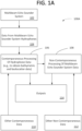
- FIG. 1A shows a survey system 100A.
- the survey system includes an echo sounder system such as a multibeam echo sounder system 102 which may be mounted on a surface vehicle or vessel, a remotely operated vehicle, an autonomous underwater vehicle, or the like.
- echo sounder and/or survey system outputs 114 may be contemporaneous with echo sounder processing of hydrophone data as in some embodiments for bathymetry or non-contemporaneous with processing of hydrophone data as in some embodiments for waterbody bottom classification.
- Data acquired by multibeam echo sounder systems 104 includes data from echo sounder listening devices such as hydrophones (e.g., transducers) that receive echoes which are related to the acoustic/pressure waves emanating from the echo sounder projectors but have returned by virtue of an interaction with inhomogeneities of many kinds.
- the interactions may take the form of reflection or scattering.
- the inhomogeneities also known as reflectors and/or scattering centers, represent discontinuities in the physical properties of the medium.
- Exemplary scattering centers may be found in one or more of i) an ensonified volume of the waterbody such as a water column, ii) upon the ensonified surface of the bottom, or iii) within the ensonified volume of the sub-bottom.
- Scattering centers of a biological nature may be present in the water column, as they are a part of the marine life.
- Scattering centers of a nonbiological nature may be present in the water column in the form of bubbles, dust and sand particles, thermal microstructure, and turbulence of natural or human origin, such as ships' wakes.
- Scattering centers on the surface of the bottom may be due to the mechanical roughness of the bottom, such as ripples, or be due to the inherent size, shape and physical arrangement of the bottom constituents, such as mud, sand, shell fragments, cobbles and boulders, or due to both factors.
- Scattering centers in the sub-bottom may be due to bioturbation of the sediments, layering of different sediment materials within the bottom, or buried manmade structures such as pipelines.
- Data processing within the echo sounder system may include contemporaneous processing of hydrophone data 106, for example to obtain bathymetric and/or backscatter data.
- Data processing may also include non-contemporaneous processing of multibeam echo sounder system data 108, for example to characterize the environment including bottom conditions or the water column.
- Data processing may include utilization of complementary or other data.
- contemporaneous processing of hydrophone data 106 may utilize contemporaneous 110 and/or non-contemporaneous 112 data such as contemporaneously collected global positioning system ("GPS") data, sound speed measurements, attitude, and navigational information.
- non-contemporaneous processing of echo sounder system data may utilize contemporaneous 110 and/or non-contemporaneous 112 data such as non-contemporaneously collected waterbody bottom composition data and tidal records.
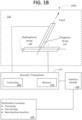
- FIG. 1B shows portions of an exemplary multibeam echo sounder system ("MBES") 100B.
- the echo sounder system includes a transducer section 120 and an acoustic transceiver 122.
- the echo sounder system may include a transceiver interface such as an interface module 124 and/or a workstation computer 126 for one or more of data processing, data storage, and interfacing man and machine.
- Exemplary transducers, shown here in a Mills Cross arrangement 120 include a transmitter or projector array 130 and a receiver or hydrophone array 140. Projectors in the projector array may be spaced along a line that is parallel with a keel line or track of a vehicle or vessel to which they are mounted which may be referred to as an along track arrangement.
- a receiver of the transceiver 122 has an operating frequency range matched with that of the projectors and/or the hydrophones.
- the acoustic transceiver 122 includes a transmitter section 150 and a receiver section 170.
- the acoustic transceiver may be configured to transmit to a single projector array 130 and to receive from a single hydrophone array 140. In some embodiments, such a transceiver may be said to operate with a single transmitter array and a single receiver array. Unless otherwise noted, the term transceiver does not require common transmitter and receiver packaging.
- a single projector array ensonifies the entirety of a swath on a single ping.
- a projector array may be a single projector array regardless of the geometry, arrangement, or quantity of devices employed.
- the plural projectors are a single projector array if they are operated to ensonify the entirety of a swath on a single ping.
- the echo sounder may further include a means such as an interface module 124 for interconnection with the transceiver 122.
- This interface module may provide, among other things, a power supply for the transceiver, communications with the transceiver, communications with the workstation computer 126, and communications with other sources of data such as a source of contemporaneous GPS data.
- the workstation computer 126 may provide for one or more of data processing such as data processing for visualization of survey results, for data storage such as storage of bathymetry data and backscatter data, for user inputs, and for display of any of inputs, system status, and survey results.
- data processing such as data processing for visualization of survey results
- data storage such as storage of bathymetry data and backscatter data
- user inputs for user inputs
- display any of inputs, system status, and survey results.
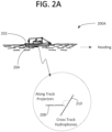
- FIGS. 2A-B show an exemplary vessel equipped with a multibeam echo sounder 200A. See for example the echo sounders of FIGS. 1A-B .
- an MBES array package 204 is affixed to a vessel 202, for example to a bottom of the vessel.
- the array package 204 Within the array package 204 is an along track array of projectors 208 and a cross track array of hydrophones 210.
- the projector array is for excitation by an echo sounder transmitter message.
- the hydrophone array is for receiving echoes of the transmitted message.
- a crossed array arrangement such as a Mills Cross arrangement of the projector and hydrophone arrays enables the echo sounder to operate with crossed transmit and receive beams wherein the cross intersection identifies a particular waterbody location, area, or cell.
- the crossed arrays may be in a perpendicular or a substantially perpendicular arrangement.
- Substantially perpendicular refers to generally small deviations from perpendicular caused by any of array assembly tolerances, mounting tolerances, adjustment tolerances, and the like.
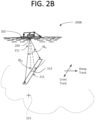
- FIG. 2B shows bottom ensonification 200B.
- an across track strip or fan of a waterbody bottom 212 is ensonified by the projector array 208.
- the along track projector array 208 ensonifies an across track fan 212.
- the projected beam 211 has a wide across track aperture angle ⁇ t1 as compared with a relatively narrow along track aperture angle ⁇ t2 . Echoes from this ensonified fan are received by the hydrophone array 210.
- MBES receiver beam steering enables subdivision of the fan 212 into a series of zones. This subdivision into zones enables identification of an echo returned from a particular zone or location 213 on the waterbody bottom 215.
- the vessel when the fan 212 is ensonified, the vessel is in a particular position relative to the waterbody bottom 215.
- the echo returned from the waterbody bottom location 213 may be said to have been acquired from a particular perspective with the MBES in a particular position relative to the waterbody bottom location.
- echo data for a particular waterbody bottom location includes data from multiple different perspectives
- this data can be used to test assumptions made about the environment that propagates the echoes.
- Multi-perspective ensonification includes a process of operating MBES projectors at multiple vessel locations such that a site on the waterbody bottom is ensonified multiple times from multiple different perspectives.
- echo data ed1 from a zone z1 within the ensonified area is acquired.
- echo data ed2 from a zone z2 that overlaps zone z1 may be acquired.
- zones z 1 and z 2 are at least partially superimposed, an overlap is defined.
- the site may be ensonified from multiple perspectives and echo data may be acquired from multiple perspectives.
- different perspectives result when the MBES pitch angles ensonifying zones z 1 and z 2 differ.
- acquiring multiple echoes from the same site may be referred to as a part of a multi-perspective survey, multi-echo ray tracing, multi-look echo sounding, and/or multi-perspective ensonification, echoes, or queries.
- FIGS. 2C-D show an antiparallel track survey plan aimed at acquiring multi-perspective survey data 200C-D.
- an MBES transducer plane x-z is at level yt and a waterbody bottom 215 plane x'-z' is at level yb.
- Survey vessel tracks are located in the upper x-z plane. As shown, the survey vessel movement along a first track Track 1 is parallel to and opposite of survey vessel movement along a second track Track 2. In some embodiments, deviations from parallel tracks arise from vessel instrument measurement inaccuracies, course and or heading errors arising from sea conditions, and the like. In some embodiments similar multi-perspective survey results are provided by non-opposed track directions.
- Operation of MBES projectors on a vessel traversing Track 1 may, with a beam angle of ⁇ t1, ensonify a first waterbody bottom fan f1.
- operation of the MBES projectors while traversing Track 2 may, with a beam angle of ⁇ t11, ensonify a second waterbody bottom fan f2.
- the beam angles may be equal or not.
- a portion of the waterbody bottom is ensonified twice.
- a first ensonification from Track 1 is from a first perspective and a second ensonification from Track 2 is from a second perspective.
- MBES operation on Track 1 results in ensonification of fan f1 which includes ensonification of cell c1 and ensonification Ap of a site within cell c1.
- MBES operation on Track 2 results in ensonification of fan f2 which includes ensonification Bp of the same site within cell c2.
- ensonification A p and its echo A h may precede ensonification B p and its echo B h .
- This example shows an antiparallel track survey plan where a site defined by an overlap (an overlap, site, or overlap site) is ensonified from a first perspective on Track 1 and from a second perspective on Track 2.
- the first perspective is the location of g1 on Track 1 relative to the overlap site and the second perspective is the location of g2 on Track 2 relative to the overlapped.
- FIGS. 2E-F show a cross track survey plan aimed at acquiring multi-perspective survey data 200E-F.
- an MBES transducer plane x-z is at level yt and a waterbody bottom 215 plane x'-z' is at level yb.
- Survey vessel tracks, Track 1 and Track 2 are located in the upper x-z plane. As shown, the tracks cross at an angle ⁇ . In some embodiments, angle ⁇ is about a right angle with deviations subject to vessel instrument measurement inaccuracies, course and or heading errors arising from sea conditions, and the like. In various embodiments the survey vessel direction of movement along either track may be reversed.
- Operation of MBES projectors on a vessel traversing Track 1 may, with a beam angle of ⁇ t1, ensonify a first waterbody bottom fan f1.
- operation of the MBES projectors while traversing Track 2 may, with a beam angle of ⁇ t11, ensonify a second waterbody bottom fan f2.
- the beam angles may be equal or not.
- a portion of the waterbody bottom is ensonified twice.
- a first ensonification from Track 1 is from a first perspective and a second ensonification from Track 2 is from a second perspective.
- MBES operation on Track 1 results in ensonification of fan f1 which includes ensonification of cell c1 and ensonification Ap of a site within cell c1 and a corresponding echo Ah.
- MBES operation on Track 2 results in ensonification of fan f2 which includes ensonification Bp of the same site within cell c2 and a corresponding echo Bh.
- ensonification A p and its echo A h may precede ensonification B p and its echo B h .
- This example shows a cross track survey plan where an overlap site is ensonified from a first perspective on Track 1 and from a second perspective on Track 2.
- the first perspective is the location of g1 on Track 1 relative to the overlap site and the second perspective is the location of g2 on Track 2 relative to the overlap site.
- FIGS. 2G-H show a same track survey plan aimed at acquiring multi-perspective survey data 200G-H.
- an MBES transducer plane x-z is at level yt and a waterbody bottom 215 plane x'-z' is at level yb.
- Survey vessel Track 1 is located in the upper x-z plane.
- Track 1 is a straight line.
- Track 1 deviates from a straight line.
- deviations from a straight line path include deviations due to vessel instrument measurement inaccuracies, course and or heading errors arising from sea conditions, and the like.
- the survey vessel direction of movement along the track may be reversed.
- An early operation of MBES projectors on a vessel traversing Track 1 may, with a cross track beam angle of ⁇ t1, ensonify a first plurality of waterbody bottom fans f1-f5. As shown, the fans f1-f5 extend between an along track angle ⁇ t1.
- a later operation of the MBES projectors while traversing Track 1 may, with a beam angle of ⁇ t11, ensonify a second plurality of waterbody bottom fans f1'-f5'. As shown, the fans f1'-f5' extend between an along track angle ⁇ t11.
- the angles ⁇ t1, ⁇ t11 may be equal or not.
- the angles ⁇ t1, ⁇ t11 may be equal or not.
- the early MBES projector operation produces a grid of cells located by fan f1-f5 and by zone k1-k4. For example a cell f1, k1 is ensonified by early MBES operation while a cell f5', k1 is ensonified by later MBES operation. These cells do not overlap.
- a cell f4 k1 is ensonified by early MBES operation while the same cell f1', k1 is ensonified by later MBES operation. These cells overlap.
- early MBES operation and later MBES operation provides ensonification of cell f4, k1 from a first perspective at g1 along Track 1 and ensonification of overlapping cell f1', k1 from a second perspective at g2 along Track 1.
- This example shows a same track survey plan where a site is ensonified from a first and a second perspective along Track 1.
- the first perspective is the location of g1 on Track 1 relative to the overlap site and the second perspective is the location of g2 on Track 1 relative to the overlap site.
- Estimating the propagation path(s) of acoustic energy through a waterbody may be referred to as ray tracing.
- This ray tracing may involve dividing the waterbody into layers. Tracing sound rays through a body of water may involve dividing the waterbody into layers. With defined layers, physical properties such as the speed of sound may be measured, estimated, or otherwise made available for one or more layers. The value of a particular media property may be held constant or varied, such as linearly varied, within a layer. For example, in a multi-layer media model the speed of sound may be constant within a layer or change with a constant gradient within a layer provided the speed of sound is continuous from layer to layer.
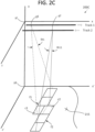
- FIGS. 2I-J show an exemplary waterbody model 200I-J.
- the waterbody includes three layers (11, 12, 13), each layer having a corresponding thickness (t1, t2, t3).
- FIG. 2I shows a first echo from a point on a waterbody bottom 283 that is traced with three ray segments.
- a first ray segment ra exits layer l3 at an angle ⁇ 3
- a second ray segment rb exits layer l2 at an angle ⁇ 2
- a third ray segment rc exits layer l1 at an angle ⁇ 1.
- the third ray segment rc leaves layer l1 at or near an MBES hydrophone array.
- ray segments like those of FIGS. 2I-J may travel through a layer and/or be modeled as traveling through a layer with no change in sound speed or with various changes in sound speed.
- sound may travel through a layer with a constant sound speed and experience no change of ray path angle resulting in a straight ray segment.
- sound may travel through a layer with a constant sound speed gradient and experience a gradual change of ray path angle resulting in a curved ray segment.
- the figures do not attempt to replicate curved ray segments.
- ray angles at layer interfaces may change abruptly with gradual continuous changes thereafter as in a prior layer.
- the slopes of adjoining rays at layer interfaces may be equal or about equal, for example within 1 to 10 percent difference.
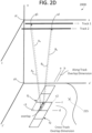
- FIG. 2J shows a second echo from the point 283 on the waterbody bottom.
- a first ray segment ra' exits layer l3 at an angle 03'
- a second ray segment rb' exits layer l2 at an angle 02'
- a third ray segment rc' exits layer l1 at an angle ⁇ 1'.
- the third ray segment leaves layer l1 at or near an MBES hydrophone array.
- the ray segments tracing the first echo are characterized by a more severe slope than those tracing the second echo. This shows, among other things, that the first and second echoes from the point on the waterbody bottom 283 correspond to ensonifications from different perspectives as discussed above.
- FIGS. 2I-J are based on a particular waterbody model and are merely illustrative.
- the number of layers used in the model may be 2, 3, 4, 5 or more.
- the value of the speed of sound may vary with depth.
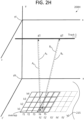
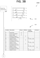
- FIGS. 3A-3G show a process for testing sound speeds used in depth estimates 300A-G.
- FIG. 3A provides an overview of the process 300A.
- a model of the waterbody where sound speeds at various depths will be estimated is constructed. See for example the models of FIGS. 2I-J .
- a survey path is selected. See for example the survey paths of FIGS. 2A-H and in particular survey paths that provide multi-perspective ensonifications of individual overlap sites.
- survey data is acquired when an MBES is operated on board a vessel that follows the selected survey path. From this data, waterbody bottom reflectors are located in a fourth step.
- the waterbody bottom may be divided using a square grid into colocation areas that are one meter on a side.
- grid size may vary with water depth owing to beam footprints that vary with depth.
- step 350 colocated reflectors are identified using a method such as the one just described. Because colocated reflectors are found in a small area on the waterbody bottom, the depth estimate made for each of the reflectors should be closely similar or, perhaps within measurement accuracy, the same. Notably, reducing the grid size reduces the variation in actual depths among a group of colocated reflectors.
- step 360 disagreements in depth estimates are characterized in a quantitative manner.
- step seven 370 the sensitivity in depth disagreements to sound speed perturbations is quantified.
- step eight 380 the depth estimate disagreements are reduced or minimized by selecting speed of sound values that achieve this result. In an embodiment, the process ends thereafter at step 390.
- FIGS. 3B-3G which follow provide a flowchart with process step details 300B-G.
- the flowchart starts with modeling the environment in step 310.
- a waterbody model 312 provides four layers l1-l4 with respective layer thicknesses t1-t4.
- the sound speeds entering and leaving the waterbody are c1 and c5 while the sound speeds at layer boundaries are c2-c4.
- Angles of refraction entering each layer are ⁇ 1- ⁇ 4 and the angle of refraction leaving layer l4 is ⁇ 5.
- ray segments like those of the waterbody model 312 may travel through a layer and/or be modeled as traveling through a layer with no change in sound speed or with various changes in sound speed.
- sound may travel through a layer with a constant sound speed and experience no change of ray path angle resulting in a straight ray segment.
- sound may travel through a layer with a constant sound speed gradient and experience a gradual change of ray path angle resulting in a curved ray segment.
- the figures do not attempt to replicate curved ray segments.
- ray angles at layer interfaces may change abruptly with gradual continuous changes thereafter as in a prior layer.
- the slopes of adjoining rays at layer interfaces may be equal or about equal, for example within 1 to 10 percent difference.
- a table alongside the flowchart 314 includes selected variables and their descriptions.
- Known variables in the table are travel time tt for an acoustic message emitted by the projectors 208 and received by the hydrophones 210, sound speed at the launch c1, launch angle ⁇ 1.
- User defined variables are the thicknesses t1-t3 of layers of waterbody layers l1-l3.
- Initially estimated variables in the table are sound speeds c2-c5 and angles of refraction ⁇ 2- ⁇ 5.
- the unknown variable in the table is the thickness of layer l4.
- FIG. 3C is a continuation 300C of the flowchart of FIG. 3B as indicated by link f1.
- step 320 a survey path is selected. As shown alongside the flowchart, the survey path selected is an antiparallel track path 322. Track B overlaps Track A, the direction of Track B being opposite the direction of Track A.
- the ensonification of a Track A cell 325 and the subsequent ensonification of an overlapping Track B cell 327 is intended to provide echoes from multiple perspectives.
- echoes resulting from the first ensonification of colocated reflectors are from a perspective other than that of echoes resulting from the second ensonification of the colocated reflectors.
- any of several survey paths might be selected including parallel tracks in the same or opposed directions, cross tracks in similar or opposed directions, and same track forward and backward look directions. Further, any combinations of these paths may be chosen to provide multiple echoes from differing perspectives from each of plural reflectors.
- An acquired data step 330 includes an ensonification step 332 where multiple "i" areas (Ai, A2... Ai) are ensonified with "i” pings (P1, P2... Pi) to obtain echoes from "i" perspectives. Also included is a receive returns step 334 where waterbody bottom reflectors return echoes from these pings and round trip travel times of those echoes are measured for all beams, fans, and pings.
- step 340 Given measured travel time information and the modeled sound speed profile, in step 340 acoustic paths through the layers of the waterbody model 312 between the MBES and ensonified reflectors are modeled.
- A1 A2, A3 ray tracing to reflectors provides coordinates x, y, z specific to each reflector.
- matrices 326 for respective areas PA1, PA2, PA3 provide coordinates for reflectors therein.
- seven or more sets of reflector coordinates appear in each matrix and indicate returns from corresponding reflectors in each of the areas.
- Coordinate indicia indicate a reflector number (e.g., 1-7) and an area that confines the reflector (e.g., A1, A2, A3).
- FIG. 3D is a continuation 300D of the flowchart of FIG. 3C as indicated by link f2.
- groups of reflectors may be considered as "colocated" or as representative of a single location on a waterbody bottom such as a location having a single or substantially invariant depth such as a depth that varies within a survey map tolerance, survey instrument tolerance, selected tolerance, or similar industry tolerance.
- a step of finding colocated reflectors 350 includes an identification step 352, a collection step 354, and a rewrite step 356.
- colocated reflectors are identified as reflectors having the same or similar x, y coordinates across all three of the matrices PA1, PA2, PA3 are marked 353.
- coordinate pairs x 2,A1 , y 2,A1 and x 5,A2 , y 5,A2 and x 1,A3 , y 1,A3 identify a 1 st same or similar waterbody bottom location.
- coordinate pairs x 6,A1 , y 6,A1 and x 7,A2 , y 7,A2 and x 4,A3 , y 4,A3 identify a 2 nd same or similar waterbody bottom location.
- coordinate pairs x 4,A1 , y 4,A1 and x 3,A2 , y 3,A2 and x 6,A3 , y 6,A3 identify a 3 rd same or similar waterbody bottom location.
- Reflector coordinates may be said to identify a similar location when they are situated within a selected colocation area, for example within an area of one square meter. Reflector coordinates may be said to identify a similar location when they lie within a colocation circle, for example a circle having a diameter of one meter. Similarly located reflectors may be identified by overlaying and dividing the waterbody bottom with a pattern such as a grid, regular grid, or square grid and designating each area so identified as a colocation area. For example, where a regular grid such as a square grid is used, areas identified within the grid may be colocation areas such that reflectors falling within a particular grid defined area are colocated reflectors with similar x, y coordinates.
- the coordinates of similarly located reflectors are collected 355 in three matrices CP1, CP2, CP3.
- a simplification in matrix presentation results from rewriting the indices in a manner suggesting that for a given matrix the x,y coordinates are the same or similar.
- the multiple colocated x and y coordinates of the matrices 355 are assigned a single x and y value to represent the group, for example using an average, grid center or area center. See in particular indices of x, y, z, are rewritten in matrices CPT1, CPT2, CPT3 that correspond to matrices CP1, CP2, CP3.
- indices of x, y, z are rewritten in matrices CPT1, CPT2, CPT3 that correspond to matrices CP1, CP2, CP3.
- remarking the indices of x and y to be the same within a given matrix emphasizes the equality or similarity of the x, y pairs in the matrix, for example x 1 , y 1 for all of the x, y pairs in matrix CPT1.
- the z coordinates are not necessarily equal or similar. As such, they are remarked as z a,b where "a" is constant in a particular matrix and "b" varies from row to row in the matrix. For example, in the first matrix CPT1 the z coordinates by row are z 1,1 , z 1,2 , z 1,3 .
- a respective location x, y corresponds with three different depth estimates.
- the location x1,y1 corresponds with depth estimates z a,1 , z a,2 , z a,3 .
- the depth estimates in each matrix 357 should be the same even though they are not. Equality may be assumed because, for each matrix, the depth estimates correspond with a group of colocated reflectors. As such, the depth estimates in a particular matrix may be viewed as samples or sample values "s" of the same environmental variable at a particular location.
- the goodness of this same matrix/same depth assumption depends on variables including the regularity of the waterbody bottom and the characteristic dimension(s) and/or pattern(s) used to identify colocated reflectors.
- various methodologies for testing and/or improving depth estimates may manipulate variables such as sound speed(s) to reduce the variability in depth estimates for each group and/or multiple groups of colocated reflectors.
- FIG. 3E is a continuation 300E of the flowchart of FIG. 3D as indicated by link f3.
- a step of characterizing disagreement in depth estimates includes a step establishing a basis to characterize differences 360 and the step of characterizing the disagreement 362.
- step 360 establishes a basis for characterizing differences in depth estimates.
- a mean value matrix z as shown below expresses this basis.
- step 364 provides for each group of colocated reflectors a measure of the disagreement among depth estimates as expressed by vector d shown in the equation below.
- FIG. 3F is a continuation 300F of the flowchart of FIG. 3E as indicated by link f4.
- the gradient matrix is a metric of the sensitivity of depth estimates to modeled sound speeds and is constructed by first perturbing the values of sound speed c 2 ... c p by a positive increment and then by a negative increment. Then, for each perturbation, steps are repeated including the steps of determining reflector locations 340, finding colocated reflectors 350, and characterizing disagreements in depth estimates 360 with vectors d+ and d - .
- a counter p counts from 2 to 5 indicating values of the speed of sound c 2 ... c 5 consistent with a four layer waterbody model having five corresponding values of the speed of sound c 1 ... c 5 where c 1 is a known value of the speed of sound at the launch.
- step 372 a positive perturbation (+ ⁇ ) is applied to a p th sound speed value c p .
- Steps 340-364 are repeated and vector d p+ is populated 376.
- the p th sound speed value c p is then reset.
- step 373 a negative perturbation (- ⁇ ) is applied to the p th sound speed value c p .
- Steps 340-364 are repeated and vector d p- is populated 377.
- the p th sound speed value c p is then reset.
- step 374 a p th row of the gradient matrix G is populated.
- G p,i (d p+,i - d p-,i )/2 mag( ⁇ ) where counter i varies from 1 to n to populate 378 the columns of the matrix G, each value of i representing the i th group of colocated reflectors.
- counter p indexes to the next value in step 375 and steps 372-374 are repeated.
- the process proceeds to step 382 of the minimize disagreement block 380.
- FIG. 3G is a continuation 300G of the flowchart of FIG. 3F as indicated by link f5.
- disagreements among depth estimates in each group of colocated reflectors are simultaneously minimized utilizing conventional least-squares techniques associated with linear algebra.
- an equation utilizing the gradient matrix G and disagreement in depth estimates vector d provides a vector of corrections mhat to be applied to sound speed values to reduce or minimize depth disagreements.
- the equation presented 382 is a well-known least-squares minimizing solution whose derivation is available in academic texts such as the text by Munk, Walter, et al., Ocean Acoustic Tomography, Cambridge University Press, 1995 .
- the equation provides two terms for conveying prior information, if known, about the noise or solutions.
- the diagonal of matrix R can be populated with the relative sizes of noise variance associated with each observation in vector d.
- the diagonal of matrix S can be populated with the relative sizes of the elements of mhat.
- each of the sound speed values c2... c5 is corrected using the correction vector mhat.
- the above solution procedure is based on a multilayer waterbody model with a known sound speed c 1 at launch and initial estimates or otherwise available values of sound speed at the layer interfaces and at the waterbody bottom.
- cases may arise where the only available value(s) of sound speed are sound speed value(s) at launch.
- a survey conducted with equipment malfunction(s) or human error(s) may result in such a case.
- a survey conducted with the intent to estimate sound speed values after the survey is conducted may result in such a case.
- the system and method of the present invention may be used to synthesize a sound speed profile.
- the system and method of the present invention may be used to synthesize a sound speed profile through a waterbody modeled with a plurality of layers.
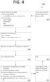
- FIG. 4 shows a method for synthesizing a sound speed profile where a waterbody is modeled with multiple layers 400. Steps in this synthesis method corresponding to those mentioned above (see e.g., FIGS. 3A-G ) may be carried out in a similar manner.
- a first step 410 the need for synthesizing a sound speed profile is evaluated. Where there is a need, the process proceeds to a second step 420.
- known variables are identified.
- knowns may be sound speed at a Mills Cross transducer array, launch angle, travel time, GPS data, and vessel heading/tilt/roll data.
- the environment is modeled.
- c 1 is known and for j layers the sound speed is set to c 1 such that in each layer the speed of sound is the same.
- ray tracing locates reflectors in a fourth step 440. And, finding groups of colocated reflectors follows in a fifth step 450.
- step 460 i) disagreements in depth estimates are characterized in a manner similar to that described in step 360 above, ii) a gradient matrix is constructed in a manner similar to that described in step 370 above, iii) disagreements among depth estimates in each group of colocated reflectors are reduced in a manner similar to that described in step 380 above, iv) sound speed adjustments are calculated in a manner similar to that described in step 380 above, and v) sound speed adjustments are applied as suggested above. Using the adjusted values of sound speed, a survey may be created in step 470. Following step 470 is an end step 480.
- a threshold value that when compared to a function of the measured depth disagreements indicates whether the assumed sound speed profile differs from the real environment.
Landscapes
- Engineering & Computer Science (AREA)
- Radar, Positioning & Navigation (AREA)
- Remote Sensing (AREA)
- Physics & Mathematics (AREA)
- Computer Networks & Wireless Communication (AREA)
- General Physics & Mathematics (AREA)
- Acoustics & Sound (AREA)
- Measurement Of Velocity Or Position Using Acoustic Or Ultrasonic Waves (AREA)
- Investigating Or Analyzing Materials By The Use Of Ultrasonic Waves (AREA)
Claims (15)
- Mehrperspektivisches Beschallungsverfahren, umfassend die folgenden Schritte:Installieren eines Mehrstrahl-Echolotsystems, MBES (multibeam echo sounder system), (100; 102) auf einem Wasserfahrzeug derart, dass mehrere Wandler in einem einzigen MBES-Projektorarray (130) und mehrere Wandler in einem einzigen MBES-Hydrophonarray (140) in einer Mills-Cross-Anordnung vorliegen;Modellieren eines Wasserkörpers mit einer Vielzahl von "j" sich überlagernden Schichten (L1 ... L j), die jeweilige Schichtdicken (ti ... tj) aufweisen, wobei jede der j Schichten eine derartige Schichteingangsschallgeschwindigkeit und Schichtausgangsschallgeschwindigkeit aufweist, dass ein Satz von (j + 1) Schallgeschwindigkeitswerten (ci, c2 ... cj + i) das Schallgeschwindigkeitsprofil durch die Schichten charakterisiert;Entwerfen einer Fahrzeugroute und Befahren der Route derart, dass während des MBES-Betriebs entlang der Route i) mehrere Primärbereiche beschallt werden, ii) mehrere Sekundärbereiche beschallt werden, iii) jeder Primärbereich von einem jeweiligen Sekundärbereich überlappt wird und iv) bei jeder Überlappung ein davon ausgehendes erstes Echo einen ersten Weg zu dem MBES an einem ersten Ort durchläuft und ein davon ausgehendes zweites Echo einen zweiten Weg zu dem MBES an einem von dem ersten Ort verschiedenen zweiten Ort durchläuft;Modellieren der Schallausbreitung durch den Wasserkörper zum Lokalisieren eines das Echo zurücksendenden Reflektors in drei Dimensionen über eine jedem Echo entsprechende Laufzeit;wobei eine der Dimensionen eine Wasserkörpertiefe angibt und die anderen zwei Dimensionen Koordinaten in einer Reflektorebene parallel zu der freien Wasserkörperoberfläche angeben;Auswählen einer Kolokationsmetrik und Verwenden der Metrik zum Identifizieren von Gruppen von Reflektoren, die in der Reflektorebene kolokalisiert sind,Quantifizieren von Unstimmigkeiten der Wasserkörpertiefen, die den Reflektoren in der Gruppe entsprechen, für jede Gruppe von kolokalisierten Reflektoren; undBestimmen eines Satzes von angepassten Schallgeschwindigkeitswerten, die dazu neigen, die Unstimmigkeit innerhalb jeder Gruppe von Tiefenschätzungen gleichzeitig zu reduzieren.
- Verfahren nach Anspruch 1, wobei der erste Echoweg einem ersten Strahlwinkel entspricht und der zweite Echoweg einem zweiten Strahlwinkel entspricht.
- Verfahren nach Anspruch 1, wobei die angepassten Schallgeschwindigkeitswerte eine Funktion von Unstimmigkeiten von Tiefenschätzungen sind, die bei i) angenommenen Schallgeschwindigkeiten (ci, c2 ...) und bei ii) Störwerten von angenommenen Schallgeschwindigkeiten (ci, c2 ...)p bewertet werden.
- Verfahren nach Anspruch 3, wobei ein sich nicht schneidender erster und zweiter Vermessungsschiffkurs derart gewählt werden, dass ein Betreiben des MBES während des Befahrens der Kurse zu (i) einem mindestens teilweise überlagerten ersten und zweiten Wasserkörpergrundfächer, die sich an einer Stelle überlappen, und zu (ii) multiplen Echos von multiplen kolokalisierten Reflektoren an der Stelle resultiert.
- Verfahren nach Anspruch 3, wobei ein sich schneidender erster und zweiter Vermessungsschiffkurs derart gewählt werden, dass ein Betreiben des MBES während des Befahrens der Kurse zu (i) einem mindestens teilweise überlagerten ersten und zweiten Wasserkörpergrundfächer, die sich an einer Stelle überlappen, und zu (ii) multiplen Echos von multiplen kolokalisierten Reflektoren an der Stelle resultiert.
- Verfahren nach Anspruch 3, wobei der MBES-Betrieb während des Befahrens eines einzelnen Kurses zu (i) einem mindestens teilweise überlagernden ersten und zweiten Wasserkörperfächer, die sich an einer Stelle überlappen, und zu (ii) multiplen Echos von multiplen kolokalisierten Reflektoren an der Stelle resultiert.
- Verfahren nach Anspruch 6, wobei der erste Wasserkörperfächer aus einem vorwärts geneigten Fächer zu Zeitpunkt1 und der zweite Wasserkörperfächer aus einem rückwärts geneigten Fächer zu Zeitpunkt2 resultiert, wobei Zeitpunkt2 > Zeitpunkt1.
- Verfahren nach Anspruch 1, ferner umfassend die Schritte des Betreibens des Fahrzeugs und des MBES zum Durchführen einer bathymetrischen Vermessung;Zuweisen jedes Reflektors zu einer von multiplen Zonen, die die Reflektorebene unterteilen, unter Verwendung der Kolokationsmetrik; undwobei der gleichen Zone zugewiesene Reflektoren kolokalisierte Reflektoren sind.
- Verfahren nach Anspruch 8, wobei jede der multiplen Zonen eine jeweilige Gruppe von 2 bis 100 kolokalisierten Reflektoren beinhaltet.
- Verfahren nach Anspruch 9, wobei die Zonen eine charakteristische Dimension aufweisen, die eine Funktion einer Strahlbreite und einer Höhe ist, die vertikal zwischen dem MBES und einem Wasserkörpergrund gemessen wird.
- Verfahren nach Anspruch 9, wobei die Zonen eine charakteristische Dimension aufweisen, die proportional mit der Wassertiefe variiert.
- Verfahren nach Anspruch 8, wobei j = 4, c1 gemessen wird und angepassten Schallgeschwindigkeitswerte c2, c3, c4, c5 beinhalten.
- Verfahren nach Anspruch 8, wobei die quantifizierten Unstimmigkeiten der Tiefenschätzungen zum Konstruieren eines Systems von simultanen Gleichungen verwendet werden, das überbestimmt ist, wobei mehrere Anpassungen jeweiliger Schallgeschwindigkeitswerte durch eine Lösung der Gleichungen angegeben werden.
- Verfahren nach Anspruch 3, wobei die Schallgeschwindigkeitswerte unter Verwendung des einen oder der mehreren angepassten Schallgeschwindigkeitswerte korrigiert werden.
- Verfahren nach Anspruch 3, wobei ein Teil einer bathymetrischen Vermessungskarte korrigiert wird, wenn Daten, die zum Erstellen der Karte verwendet werden, zum Finden angepasster Schallgeschwindigkeitswerte verwendet werden und die Vermessungskarte durch Ersetzen von Schallgeschwindigkeitswerten in den Daten durch angepasste Schallgeschwindigkeitswerte neu erstellt wird.
Priority Applications (1)
| Application Number | Priority Date | Filing Date | Title |
|---|---|---|---|
| EP24218510.6A EP4495628A3 (de) | 2017-07-03 | 2018-06-24 | System und verfahren für multiperspektive ensonifikation |
Applications Claiming Priority (2)
| Application Number | Priority Date | Filing Date | Title |
|---|---|---|---|
| US201762528354P | 2017-07-03 | 2017-07-03 | |
| PCT/US2018/039189 WO2019010022A1 (en) | 2017-07-03 | 2018-06-24 | SYSTEM AND METHOD FOR MULTI-PERSPECTIVE INSONIFICATION |
Related Child Applications (1)
| Application Number | Title | Priority Date | Filing Date |
|---|---|---|---|
| EP24218510.6A Division EP4495628A3 (de) | 2017-07-03 | 2018-06-24 | System und verfahren für multiperspektive ensonifikation |
Publications (3)
| Publication Number | Publication Date |
|---|---|
| EP3449281A1 EP3449281A1 (de) | 2019-03-06 |
| EP3449281A4 EP3449281A4 (de) | 2020-01-29 |
| EP3449281B1 true EP3449281B1 (de) | 2025-01-08 |
Family
ID=64738667
Family Applications (2)
| Application Number | Title | Priority Date | Filing Date |
|---|---|---|---|
| EP24218510.6A Pending EP4495628A3 (de) | 2017-07-03 | 2018-06-24 | System und verfahren für multiperspektive ensonifikation |
| EP18782867.8A Active EP3449281B1 (de) | 2017-07-03 | 2018-06-24 | Mehrperspektivisches beschallungssystem und -verfahren |
Family Applications Before (1)
| Application Number | Title | Priority Date | Filing Date |
|---|---|---|---|
| EP24218510.6A Pending EP4495628A3 (de) | 2017-07-03 | 2018-06-24 | System und verfahren für multiperspektive ensonifikation |
Country Status (4)
| Country | Link |
|---|---|
| US (4) | US10429505B2 (de) |
| EP (2) | EP4495628A3 (de) |
| DK (1) | DK3449281T3 (de) |
| WO (1) | WO2019010022A1 (de) |
Families Citing this family (8)
| Publication number | Priority date | Publication date | Assignee | Title |
|---|---|---|---|---|
| EP4145176B1 (de) * | 2016-04-29 | 2025-09-17 | R3Vox Ltd. | Sonardatenkompression |
| US10132924B2 (en) * | 2016-04-29 | 2018-11-20 | R2Sonic, Llc | Multimission and multispectral sonar |
| US10067228B1 (en) * | 2017-09-11 | 2018-09-04 | R2Sonic, Llc | Hyperspectral sonar |
| JP7507753B2 (ja) * | 2018-10-10 | 2024-06-28 | ファーサウンダー, インコーポレイテッド | 機械学習を用いた3次元前方探知ソナー標的認識 |
| US11035970B2 (en) * | 2019-06-19 | 2021-06-15 | Magseis Ff Llc | Interleaved marine diffraction survey |
| CN110254618A (zh) * | 2019-06-28 | 2019-09-20 | 中船黄埔文冲船舶有限公司 | 一种船舶多波束换能器阵列的安装装置及其安装方法 |
| US11914066B1 (en) | 2020-03-05 | 2024-02-27 | Johnson Outdoors Inc. | Multiplexed phased array multibeam sonar |
| CN113011006B (zh) * | 2021-02-25 | 2021-10-22 | 中国科学院声学研究所 | 一种基于互相关函数脉冲波形匹配的目标深度估计方法 |
Family Cites Families (60)
| Publication number | Priority date | Publication date | Assignee | Title |
|---|---|---|---|---|
| US3144631A (en) | 1962-01-09 | 1964-08-11 | Gen Instrument Corp | Radiation mapping system |
| US5208785A (en) | 1990-09-26 | 1993-05-04 | Rowe, Deines Instruments Incorporated | Broadband acoustic doppler current profiler |
| US5243988A (en) * | 1991-03-13 | 1993-09-14 | Scimed Life Systems, Inc. | Intravascular imaging apparatus and methods for use and manufacture |
| US5200931A (en) * | 1991-06-18 | 1993-04-06 | Alliant Techsystems Inc. | Volumetric and terrain imaging sonar |
| US5287330A (en) * | 1993-01-04 | 1994-02-15 | Westinghouse Electric Corp. | Sonar apparatus |
| US6195608B1 (en) * | 1993-05-28 | 2001-02-27 | Lucent Technologies Inc. | Acoustic highway monitor |
| US5318028A (en) * | 1993-06-07 | 1994-06-07 | Westinghouse Electric Corporation | High resolution ultrasound mammography system and boundary array scanner therefor |
| US5323362A (en) * | 1993-06-07 | 1994-06-21 | Westinghouse Electric Corporation | Sonar system employing synthetic orthogonal array |
| US5433202A (en) * | 1993-06-07 | 1995-07-18 | Westinghouse Electric Corporation | High resolution and high contrast ultrasound mammography system with heart monitor and boundary array scanner providing electronic scanning |
| US5608689A (en) * | 1995-06-02 | 1997-03-04 | Seabeam Instruments Inc. | Sound velocity profile signal processing system and method for use in sonar systems |
| US5596549A (en) * | 1995-07-06 | 1997-01-21 | Northrop Grumman Corporation | Side look sonar apparatus and method |
| TW529942B (en) | 1996-06-15 | 2003-05-01 | Ying-Jiun Huang | Sport goggles with shock absorption |
| CA2240916C (en) * | 1998-05-15 | 2010-04-06 | International Road Dynamics Inc. | Truck traffic monitoring and warning systems and vehicle ramp advisory system |
| NO307014B1 (no) | 1998-06-19 | 2000-01-24 | Omnitech As | Fremgangsmåte for frembringelse av et 3D-bilde |
| CN1192213C (zh) * | 1998-06-26 | 2005-03-09 | 塞德拉公司 | 利用声压测量管道中的流体参数的装置和方法 |
| US6285628B1 (en) * | 1999-09-13 | 2001-09-04 | L3 Communications Corporation | Swept transit beam bathymetric sonar |
| JP4516644B2 (ja) * | 1999-09-29 | 2010-08-04 | 古野電気株式会社 | 受波ビーム形成方法、受波ビーム形成装置およびマッチドフィルタ |
| US7092440B1 (en) | 2000-09-27 | 2006-08-15 | Ut-Battelle Llc | Hybrid spread-spectrum technique for expanding channel capacity |
| US7547283B2 (en) * | 2000-11-28 | 2009-06-16 | Physiosonics, Inc. | Methods for determining intracranial pressure non-invasively |
| US7035166B2 (en) * | 2002-10-21 | 2006-04-25 | Farsounder, Inc. | 3-D forward looking sonar with fixed frame of reference for navigation |
| WO2003001231A2 (en) * | 2001-06-21 | 2003-01-03 | Farsounder, Inc. | Interferometric imaging method apparatus and system |
| FR2827392B1 (fr) * | 2001-07-13 | 2009-01-23 | Thomson Marconi Sonar Sas | Sonar d'imagerie et systeme de detection utilisant un tel sonar |
| NO315766B1 (no) * | 2002-01-28 | 2003-10-20 | Jan Terje Bjoerke | En metode for feltkalibrering av systemparametere i et multistråleekkolodd-system |
| WO2004072675A1 (en) * | 2002-11-12 | 2004-08-26 | General Dynamics Advanced Information Systems | A method and system for in-air ultrasonic acoustical detection and characterization |
| AU2003296196A1 (en) * | 2003-03-19 | 2004-10-11 | Institute Of Acoustics, Chinese Academy Of Sciences | Method and system for measuring the velocity of a vessel relative to the bottom using velocity measuring correlation sonar |
| US7972271B2 (en) * | 2003-10-28 | 2011-07-05 | The Board Of Trustees Of The Leland Stanford Junior University | Apparatus and method for phased subarray imaging |
| JP4518828B2 (ja) * | 2004-04-07 | 2010-08-04 | 古野電気株式会社 | 計量用魚群探知機および計量用魚群探知方法 |
| US7542375B2 (en) | 2006-12-05 | 2009-06-02 | Matthew Sawrie | Method for simultaneous transmission of soundwaves and, in particular, sonar pulses, without interference |
| US8305841B2 (en) | 2007-06-15 | 2012-11-06 | University Of Limerick | Method and apparatus for determining the topography of a seafloor and a vessel comprising the apparatus |
| US8220408B2 (en) * | 2007-07-31 | 2012-07-17 | Stone William C | Underwater vehicle with sonar array |
| GB2459091B (en) * | 2008-04-07 | 2012-05-23 | Thales Holdings Uk Plc | Method and system for acoustic imaging |
| US8560064B2 (en) * | 2008-07-31 | 2013-10-15 | Medtronic, Inc. | Extravascular arrhythmia induction |
| WO2010017629A1 (en) * | 2008-08-11 | 2010-02-18 | Marport Canada Inc. | Multi-function broadband phased-array software defined sonar system and method |
| US8248298B2 (en) * | 2008-10-31 | 2012-08-21 | First Rf Corporation | Orthogonal linear transmit receive array radar |
| DK2435806T3 (en) * | 2009-05-27 | 2016-08-29 | Teledyne Instruments Inc | A method and system for remotely measuring the speed of sound |
| US8317706B2 (en) * | 2009-06-29 | 2012-11-27 | White Eagle Sonic Technologies, Inc. | Post-beamforming compression in ultrasound systems |
| GB0916162D0 (en) * | 2009-09-15 | 2009-10-28 | Oceanscan Ltd | Scanning apparatus and method |
| GB2477148B (en) * | 2010-01-25 | 2014-06-18 | Sonardyne Internat Ltd | Data collection system, marine seismic survey system and method of estimating a corrected sound speed |
| US20130016584A1 (en) * | 2011-07-15 | 2013-01-17 | Teledyne Scientific & Imaging Llc | Methods and apparatus for obtaining sensor motion and position data from underwater acoustic signals |
| US9354312B2 (en) | 2012-07-06 | 2016-05-31 | Navico Holding As | Sonar system using frequency bursts |
| US8974390B1 (en) * | 2013-10-03 | 2015-03-10 | Scidea Research, Inc. | Pulse compression systems and methods |
| US10070825B2 (en) * | 2013-11-26 | 2018-09-11 | Scidea Research, Inc. | Pulse compression systems and methods |
| KR102082263B1 (ko) * | 2013-12-11 | 2020-02-27 | 광주과학기술원 | 수중위치 추정 시스템 및 방법 |
| US9448300B2 (en) * | 2014-05-28 | 2016-09-20 | Nxp B.V. | Signal-based data compression |
| US9784825B2 (en) * | 2014-07-15 | 2017-10-10 | Garmin Switzerland Gmbh | Marine sonar display device with cursor plane |
| US9664783B2 (en) * | 2014-07-15 | 2017-05-30 | Garmin Switzerland Gmbh | Marine sonar display device with operating mode determination |
| EP3268773B1 (de) * | 2015-03-09 | 2019-10-02 | Saipem S.p.A. | Detektionssystem und verfahren zur prüfung der position einer rohrleitung in einem bett eines gewässers |
| RU2608301C2 (ru) * | 2015-03-16 | 2017-01-17 | Общество с ограниченной ответственностью "Морские Инновации" | Система и способ 3d исследования морского дна для инженерных изысканий |
| CN105258684B (zh) * | 2015-10-30 | 2017-12-05 | 山东科技大学 | 基于激光点云为约束的多波束低掠射角波束归位方法 |
| FR3043788B1 (fr) * | 2015-11-13 | 2019-03-22 | Ixblue | Systeme bathymetrique et methode de bathymetrie corriges des erreurs en altitude |
| US9739881B1 (en) * | 2016-03-24 | 2017-08-22 | RFNAV, Inc. | Low cost 3D radar imaging and 3D association method from low count linear arrays for all weather autonomous vehicle navigation |
| US9869752B1 (en) * | 2016-04-25 | 2018-01-16 | Ocean Acoustical Services And Instrumentation Systems, Inc. | System and method for autonomous joint detection-classification and tracking of acoustic signals of interest |
| EP3449278B1 (de) * | 2016-04-29 | 2025-03-19 | R3Vox Ltd. | Überwachungssystem und -verfahren mit mehreren lüftern |
| EP4145176B1 (de) * | 2016-04-29 | 2025-09-17 | R3Vox Ltd. | Sonardatenkompression |
| US9817116B1 (en) * | 2016-04-29 | 2017-11-14 | R2Sonic, Llc | Acoustic doppler system and method |
| US10132924B2 (en) * | 2016-04-29 | 2018-11-20 | R2Sonic, Llc | Multimission and multispectral sonar |
| CN106886024B (zh) * | 2017-03-31 | 2019-04-30 | 上海海洋大学 | 深海多波束声线精确跟踪方法 |
| US10067228B1 (en) * | 2017-09-11 | 2018-09-04 | R2Sonic, Llc | Hyperspectral sonar |
| CN109000778A (zh) * | 2018-06-21 | 2018-12-14 | 交通运输部天津水运工程科学研究所 | 声速剖面仪计量检定装置及方法 |
| CN110146895B (zh) * | 2019-05-16 | 2021-04-20 | 浙江大学 | 基于倒置式多波束回声仪的声速剖面反演方法 |
-
2018
- 2018-06-24 EP EP24218510.6A patent/EP4495628A3/de active Pending
- 2018-06-24 DK DK18782867.8T patent/DK3449281T3/da active
- 2018-06-24 US US16/016,632 patent/US10429505B2/en active Active
- 2018-06-24 WO PCT/US2018/039189 patent/WO2019010022A1/en not_active Ceased
- 2018-06-24 EP EP18782867.8A patent/EP3449281B1/de active Active
-
2019
- 2019-07-18 US US16/516,084 patent/US11428810B2/en active Active
-
2022
- 2022-07-27 US US17/874,895 patent/US12313739B2/en active Active
-
2025
- 2025-04-29 US US19/192,672 patent/US20250258291A1/en active Pending
Non-Patent Citations (2)
| Title |
|---|
| L3 COMMUNICATION: "Multibeam Sonar Theory of Operation L-3 Communications SeaBeam Instruments", 1 January 2000 (2000-01-01), pages 1 - 107, XP055806040, Retrieved from the Internet <URL:https://www3.mbari.org/data/mbsystem/sonarfunction/SeaBeamMultibeamTheoryOperation.pdf> [retrieved on 20210520] * |
| LURTON XAVIER ET AL: "Backscatter measurements by seafloor-mapping sonars Guidelines and Recommendations A collective report by members of the GeoHab Backscatter Working Group", 2 May 2015 (2015-05-02), pages 1 - 200, XP055806042, Retrieved from the Internet <URL:https://niwa.co.nz/static/BWSG_REPORT_MAY2015_web.pdf> [retrieved on 20210520] * |
Also Published As
| Publication number | Publication date |
|---|---|
| EP4495628A3 (de) | 2025-04-09 |
| US11428810B2 (en) | 2022-08-30 |
| US20250258291A1 (en) | 2025-08-14 |
| US20200363526A1 (en) | 2020-11-19 |
| US20220404492A1 (en) | 2022-12-22 |
| US20190004174A1 (en) | 2019-01-03 |
| WO2019010022A1 (en) | 2019-01-10 |
| EP3449281A4 (de) | 2020-01-29 |
| US10429505B2 (en) | 2019-10-01 |
| EP3449281A1 (de) | 2019-03-06 |
| DK3449281T3 (da) | 2025-03-17 |
| US12313739B2 (en) | 2025-05-27 |
| EP4495628A2 (de) | 2025-01-22 |
Similar Documents
| Publication | Publication Date | Title |
|---|---|---|
| EP3449281B1 (de) | Mehrperspektivisches beschallungssystem und -verfahren | |
| US11119211B2 (en) | Acoustic doppler system and method | |
| US9588246B2 (en) | Data collection system, marine seismic survey system and method of estimating a corrected sound speed | |
| RU2439614C2 (ru) | Способ съемки рельефа дна акватории и устройство для его осуществления | |
| Xin et al. | A TOA/AOA underwater acoustic positioning system based on the equivalent sound speed | |
| RU2519269C1 (ru) | Способ съемки рельефа дна акватории и устройство для съемки рельефа дна акватории | |
| US20250216527A1 (en) | Method for determining a depth or a bathymetric profile based on an average sound speed profile, method for determining such a speed profile, and related sonar system | |
| US7366056B2 (en) | Depth sounding by acoustic pingers in a seismic spread | |
| Violante | Acoustic remote sensing for seabed archaeology | |
| RU2529207C1 (ru) | Система навигации буксируемого подводного аппарата | |
| Didier et al. | Real-time correction of sound refraction errors in bathymetric measurements using multiswath multibeam echosounder | |
| JPH0385476A (ja) | 海底探索装置 | |
| Pimentel et al. | Evaluation of the Precision of Phase-Measuring Bathymetric Side Scan Sonar Relative to Multibeam Echosounders | |
| Asada et al. | Three dimensional synthetic and real aperture sonar technologies with Doppler velocity log and small fiber optic gyrocompass for autonomous underwater vehicle | |
| Henley et al. | Performance of 3D forward looking sonar for bathymetric survey | |
| Sara | Next generation buried object scanning sonar (BOSS) for detecting buried UXO in shallow water | |
| White et al. | Multibeam echo sounders | |
| Zoltán et al. | Comparison of lakebed surveys carried out with single-beam and multibeam sonar instruments | |
| Salazar | Toward Precise Long-Range Underwater Acoustic Geo-Positioning: Utilizing Vehicle Data and Deepening the GNSS Analogy Through Uncertainty Modeling | |
| Fenton et al. | Probabilistic methods for improved self-consistency of Doppler Velocity Log range-based bathymetry | |
| Gürtürk | Seabed mapping using multibeam sonar and combining with former bathymetric data | |
| Mironov et al. | Evaluation of the Effectiveness of Hydroacoustic Surveys Using MBE for a Autonomous Surface Vehicles | |
| Barrault | Modeling the forward look sonar | |
| Fezzani et al. | Swath bathymetric data fusion application to autonomous underwater vehicles | |
| Houston et al. | Structural Acoustic UXO Detection and Identification in Marine Environments |
Legal Events
| Date | Code | Title | Description |
|---|---|---|---|
| STAA | Information on the status of an ep patent application or granted ep patent |
Free format text: STATUS: UNKNOWN |
|
| STAA | Information on the status of an ep patent application or granted ep patent |
Free format text: STATUS: THE INTERNATIONAL PUBLICATION HAS BEEN MADE |
|
| PUAI | Public reference made under article 153(3) epc to a published international application that has entered the european phase |
Free format text: ORIGINAL CODE: 0009012 |
|
| STAA | Information on the status of an ep patent application or granted ep patent |
Free format text: STATUS: REQUEST FOR EXAMINATION WAS MADE |
|
| 17P | Request for examination filed |
Effective date: 20181018 |
|
| AK | Designated contracting states |
Kind code of ref document: A1 Designated state(s): AL AT BE BG CH CY CZ DE DK EE ES FI FR GB GR HR HU IE IS IT LI LT LU LV MC MK MT NL NO PL PT RO RS SE SI SK SM TR |
|
| AX | Request for extension of the european patent |
Extension state: BA ME |
|
| A4 | Supplementary search report drawn up and despatched |
Effective date: 20200108 |
|
| RIC1 | Information provided on ipc code assigned before grant |
Ipc: G01S 7/53 20060101ALI20191220BHEP Ipc: G01S 15/88 20060101AFI20191220BHEP |
|
| DAV | Request for validation of the european patent (deleted) | ||
| DAX | Request for extension of the european patent (deleted) | ||
| STAA | Information on the status of an ep patent application or granted ep patent |
Free format text: STATUS: EXAMINATION IS IN PROGRESS |
|
| 17Q | First examination report despatched |
Effective date: 20210528 |
|
| P01 | Opt-out of the competence of the unified patent court (upc) registered |
Effective date: 20230530 |
|
| P02 | Opt-out of the competence of the unified patent court (upc) changed |
Effective date: 20230530 |
|
| RAP1 | Party data changed (applicant data changed or rights of an application transferred) |
Owner name: R3VOX LTD. |
|
| GRAP | Despatch of communication of intention to grant a patent |
Free format text: ORIGINAL CODE: EPIDOSNIGR1 |
|
| STAA | Information on the status of an ep patent application or granted ep patent |
Free format text: STATUS: GRANT OF PATENT IS INTENDED |
|
| INTG | Intention to grant announced |
Effective date: 20240304 |
|
| GRAJ | Information related to disapproval of communication of intention to grant by the applicant or resumption of examination proceedings by the epo deleted |
Free format text: ORIGINAL CODE: EPIDOSDIGR1 |
|
| STAA | Information on the status of an ep patent application or granted ep patent |
Free format text: STATUS: EXAMINATION IS IN PROGRESS |
|
| REG | Reference to a national code |
Ref country code: DE Ref legal event code: R079 Ref document number: 602018078368 Country of ref document: DE Free format text: PREVIOUS MAIN CLASS: G01S0015880000 Ipc: G01S0007530000 |
|
| INTC | Intention to grant announced (deleted) | ||
| RIC1 | Information provided on ipc code assigned before grant |
Ipc: G01S 15/89 20060101ALI20240702BHEP Ipc: G01S 7/54 20060101ALI20240702BHEP Ipc: G01S 7/53 20060101AFI20240702BHEP |
|
| GRAP | Despatch of communication of intention to grant a patent |
Free format text: ORIGINAL CODE: EPIDOSNIGR1 |
|
| STAA | Information on the status of an ep patent application or granted ep patent |
Free format text: STATUS: GRANT OF PATENT IS INTENDED |
|
| INTG | Intention to grant announced |
Effective date: 20240809 |
|
| GRAS | Grant fee paid |
Free format text: ORIGINAL CODE: EPIDOSNIGR3 |
|
| GRAA | (expected) grant |
Free format text: ORIGINAL CODE: 0009210 |
|
| STAA | Information on the status of an ep patent application or granted ep patent |
Free format text: STATUS: THE PATENT HAS BEEN GRANTED |
|
| AK | Designated contracting states |
Kind code of ref document: B1 Designated state(s): AL AT BE BG CH CY CZ DE DK EE ES FI FR GB GR HR HU IE IS IT LI LT LU LV MC MK MT NL NO PL PT RO RS SE SI SK SM TR |
|
| REG | Reference to a national code |
Ref country code: GB Ref legal event code: FG4D |
|
| REG | Reference to a national code |
Ref country code: CH Ref legal event code: EP |
|
| REG | Reference to a national code |
Ref country code: DE Ref legal event code: R096 Ref document number: 602018078368 Country of ref document: DE |
|
| REG | Reference to a national code |
Ref country code: IE Ref legal event code: FG4D |
|
| REG | Reference to a national code |
Ref country code: NL Ref legal event code: FP |
|
| REG | Reference to a national code |
Ref country code: SE Ref legal event code: TRGR |
|
| REG | Reference to a national code |
Ref country code: DK Ref legal event code: T3 Effective date: 20250310 |
|
| REG | Reference to a national code |
Ref country code: LT Ref legal event code: MG9D |
|
| REG | Reference to a national code |
Ref country code: AT Ref legal event code: MK05 Ref document number: 1758669 Country of ref document: AT Kind code of ref document: T Effective date: 20250108 |
|
| PG25 | Lapsed in a contracting state [announced via postgrant information from national office to epo] |
Ref country code: RS Free format text: LAPSE BECAUSE OF FAILURE TO SUBMIT A TRANSLATION OF THE DESCRIPTION OR TO PAY THE FEE WITHIN THE PRESCRIBED TIME-LIMIT Effective date: 20250408 |
|
| PG25 | Lapsed in a contracting state [announced via postgrant information from national office to epo] |
Ref country code: FI Free format text: LAPSE BECAUSE OF FAILURE TO SUBMIT A TRANSLATION OF THE DESCRIPTION OR TO PAY THE FEE WITHIN THE PRESCRIBED TIME-LIMIT Effective date: 20250108 |
|
| PG25 | Lapsed in a contracting state [announced via postgrant information from national office to epo] |
Ref country code: PL Free format text: LAPSE BECAUSE OF FAILURE TO SUBMIT A TRANSLATION OF THE DESCRIPTION OR TO PAY THE FEE WITHIN THE PRESCRIBED TIME-LIMIT Effective date: 20250108 |
|
| PGFP | Annual fee paid to national office [announced via postgrant information from national office to epo] |
Ref country code: DE Payment date: 20250623 Year of fee payment: 8 |
|
| PG25 | Lapsed in a contracting state [announced via postgrant information from national office to epo] |
Ref country code: ES Free format text: LAPSE BECAUSE OF FAILURE TO SUBMIT A TRANSLATION OF THE DESCRIPTION OR TO PAY THE FEE WITHIN THE PRESCRIBED TIME-LIMIT Effective date: 20250108 |
|
| PGFP | Annual fee paid to national office [announced via postgrant information from national office to epo] |
Ref country code: GB Payment date: 20250624 Year of fee payment: 8 Ref country code: DK Payment date: 20250623 Year of fee payment: 8 |
|
| PG25 | Lapsed in a contracting state [announced via postgrant information from national office to epo] |
Ref country code: IS Free format text: LAPSE BECAUSE OF FAILURE TO SUBMIT A TRANSLATION OF THE DESCRIPTION OR TO PAY THE FEE WITHIN THE PRESCRIBED TIME-LIMIT Effective date: 20250508 |
|
| PGFP | Annual fee paid to national office [announced via postgrant information from national office to epo] |
Ref country code: NO Payment date: 20250610 Year of fee payment: 8 |
|
| PGFP | Annual fee paid to national office [announced via postgrant information from national office to epo] |
Ref country code: NL Payment date: 20250623 Year of fee payment: 8 |
|
| PG25 | Lapsed in a contracting state [announced via postgrant information from national office to epo] |
Ref country code: HR Free format text: LAPSE BECAUSE OF FAILURE TO SUBMIT A TRANSLATION OF THE DESCRIPTION OR TO PAY THE FEE WITHIN THE PRESCRIBED TIME-LIMIT Effective date: 20250108 |
|
| PG25 | Lapsed in a contracting state [announced via postgrant information from national office to epo] |
Ref country code: LV Free format text: LAPSE BECAUSE OF FAILURE TO SUBMIT A TRANSLATION OF THE DESCRIPTION OR TO PAY THE FEE WITHIN THE PRESCRIBED TIME-LIMIT Effective date: 20250108 Ref country code: PT Free format text: LAPSE BECAUSE OF FAILURE TO SUBMIT A TRANSLATION OF THE DESCRIPTION OR TO PAY THE FEE WITHIN THE PRESCRIBED TIME-LIMIT Effective date: 20250508 |
|
| PGFP | Annual fee paid to national office [announced via postgrant information from national office to epo] |
Ref country code: FR Payment date: 20250611 Year of fee payment: 8 |
|
| PG25 | Lapsed in a contracting state [announced via postgrant information from national office to epo] |
Ref country code: BG Free format text: LAPSE BECAUSE OF FAILURE TO SUBMIT A TRANSLATION OF THE DESCRIPTION OR TO PAY THE FEE WITHIN THE PRESCRIBED TIME-LIMIT Effective date: 20250108 Ref country code: GR Free format text: LAPSE BECAUSE OF FAILURE TO SUBMIT A TRANSLATION OF THE DESCRIPTION OR TO PAY THE FEE WITHIN THE PRESCRIBED TIME-LIMIT Effective date: 20250409 |
|
| PG25 | Lapsed in a contracting state [announced via postgrant information from national office to epo] |
Ref country code: AT Free format text: LAPSE BECAUSE OF FAILURE TO SUBMIT A TRANSLATION OF THE DESCRIPTION OR TO PAY THE FEE WITHIN THE PRESCRIBED TIME-LIMIT Effective date: 20250108 |
|
| PGFP | Annual fee paid to national office [announced via postgrant information from national office to epo] |
Ref country code: SE Payment date: 20250624 Year of fee payment: 8 |
|
| PG25 | Lapsed in a contracting state [announced via postgrant information from national office to epo] |
Ref country code: SM Free format text: LAPSE BECAUSE OF FAILURE TO SUBMIT A TRANSLATION OF THE DESCRIPTION OR TO PAY THE FEE WITHIN THE PRESCRIBED TIME-LIMIT Effective date: 20250108 |
|
| REG | Reference to a national code |
Ref country code: DE Ref legal event code: R097 Ref document number: 602018078368 Country of ref document: DE |
|
| PG25 | Lapsed in a contracting state [announced via postgrant information from national office to epo] |
Ref country code: EE Free format text: LAPSE BECAUSE OF FAILURE TO SUBMIT A TRANSLATION OF THE DESCRIPTION OR TO PAY THE FEE WITHIN THE PRESCRIBED TIME-LIMIT Effective date: 20250108 Ref country code: CZ Free format text: LAPSE BECAUSE OF FAILURE TO SUBMIT A TRANSLATION OF THE DESCRIPTION OR TO PAY THE FEE WITHIN THE PRESCRIBED TIME-LIMIT Effective date: 20250108 |
|
| PG25 | Lapsed in a contracting state [announced via postgrant information from national office to epo] |
Ref country code: RO Free format text: LAPSE BECAUSE OF FAILURE TO SUBMIT A TRANSLATION OF THE DESCRIPTION OR TO PAY THE FEE WITHIN THE PRESCRIBED TIME-LIMIT Effective date: 20250108 |
|
| PG25 | Lapsed in a contracting state [announced via postgrant information from national office to epo] |
Ref country code: SK Free format text: LAPSE BECAUSE OF FAILURE TO SUBMIT A TRANSLATION OF THE DESCRIPTION OR TO PAY THE FEE WITHIN THE PRESCRIBED TIME-LIMIT Effective date: 20250108 |
|
| PLBE | No opposition filed within time limit |
Free format text: ORIGINAL CODE: 0009261 |
|
| STAA | Information on the status of an ep patent application or granted ep patent |
Free format text: STATUS: NO OPPOSITION FILED WITHIN TIME LIMIT |
|
| 26N | No opposition filed |
Effective date: 20251009 |