EP3448684B1 - Industrial printhead - Google Patents
Industrial printhead Download PDFInfo
- Publication number
- EP3448684B1 EP3448684B1 EP17721799.9A EP17721799A EP3448684B1 EP 3448684 B1 EP3448684 B1 EP 3448684B1 EP 17721799 A EP17721799 A EP 17721799A EP 3448684 B1 EP3448684 B1 EP 3448684B1
- Authority
- EP
- European Patent Office
- Prior art keywords
- fluid
- flow
- chamber
- dispensed
- printhead
- Prior art date
- Legal status (The legal status is an assumption and is not a legal conclusion. Google has not performed a legal analysis and makes no representation as to the accuracy of the status listed.)
- Active
Links
Images


Classifications
-
- B—PERFORMING OPERATIONS; TRANSPORTING
- B41—PRINTING; LINING MACHINES; TYPEWRITERS; STAMPS
- B41J—TYPEWRITERS; SELECTIVE PRINTING MECHANISMS, i.e. MECHANISMS PRINTING OTHERWISE THAN FROM A FORME; CORRECTION OF TYPOGRAPHICAL ERRORS
- B41J2/00—Typewriters or selective printing mechanisms characterised by the printing or marking process for which they are designed
- B41J2/005—Typewriters or selective printing mechanisms characterised by the printing or marking process for which they are designed characterised by bringing liquid or particles selectively into contact with a printing material
- B41J2/01—Ink jet
- B41J2/135—Nozzles
- B41J2/14—Structure thereof only for on-demand ink jet heads
- B41J2/1433—Structure of nozzle plates
-
- B—PERFORMING OPERATIONS; TRANSPORTING
- B41—PRINTING; LINING MACHINES; TYPEWRITERS; STAMPS
- B41J—TYPEWRITERS; SELECTIVE PRINTING MECHANISMS, i.e. MECHANISMS PRINTING OTHERWISE THAN FROM A FORME; CORRECTION OF TYPOGRAPHICAL ERRORS
- B41J2/00—Typewriters or selective printing mechanisms characterised by the printing or marking process for which they are designed
- B41J2/005—Typewriters or selective printing mechanisms characterised by the printing or marking process for which they are designed characterised by bringing liquid or particles selectively into contact with a printing material
- B41J2/01—Ink jet
- B41J2/015—Ink jet characterised by the jet generation process
- B41J2/04—Ink jet characterised by the jet generation process generating single droplets or particles on demand
-
- B—PERFORMING OPERATIONS; TRANSPORTING
- B41—PRINTING; LINING MACHINES; TYPEWRITERS; STAMPS
- B41J—TYPEWRITERS; SELECTIVE PRINTING MECHANISMS, i.e. MECHANISMS PRINTING OTHERWISE THAN FROM A FORME; CORRECTION OF TYPOGRAPHICAL ERRORS
- B41J2/00—Typewriters or selective printing mechanisms characterised by the printing or marking process for which they are designed
- B41J2/005—Typewriters or selective printing mechanisms characterised by the printing or marking process for which they are designed characterised by bringing liquid or particles selectively into contact with a printing material
- B41J2/01—Ink jet
- B41J2/135—Nozzles
- B41J2/14—Structure thereof only for on-demand ink jet heads
- B41J2/14201—Structure of print heads with piezoelectric elements
-
- B—PERFORMING OPERATIONS; TRANSPORTING
- B41—PRINTING; LINING MACHINES; TYPEWRITERS; STAMPS
- B41J—TYPEWRITERS; SELECTIVE PRINTING MECHANISMS, i.e. MECHANISMS PRINTING OTHERWISE THAN FROM A FORME; CORRECTION OF TYPOGRAPHICAL ERRORS
- B41J2/00—Typewriters or selective printing mechanisms characterised by the printing or marking process for which they are designed
- B41J2/005—Typewriters or selective printing mechanisms characterised by the printing or marking process for which they are designed characterised by bringing liquid or particles selectively into contact with a printing material
- B41J2/01—Ink jet
- B41J2/135—Nozzles
- B41J2/165—Prevention or detection of nozzle clogging, e.g. cleaning, capping or moistening for nozzles
-
- B—PERFORMING OPERATIONS; TRANSPORTING
- B41—PRINTING; LINING MACHINES; TYPEWRITERS; STAMPS
- B41J—TYPEWRITERS; SELECTIVE PRINTING MECHANISMS, i.e. MECHANISMS PRINTING OTHERWISE THAN FROM A FORME; CORRECTION OF TYPOGRAPHICAL ERRORS
- B41J2/00—Typewriters or selective printing mechanisms characterised by the printing or marking process for which they are designed
- B41J2/005—Typewriters or selective printing mechanisms characterised by the printing or marking process for which they are designed characterised by bringing liquid or particles selectively into contact with a printing material
- B41J2/01—Ink jet
- B41J2/135—Nozzles
- B41J2/14—Structure thereof only for on-demand ink jet heads
- B41J2002/14467—Multiple feed channels per ink chamber
-
- B—PERFORMING OPERATIONS; TRANSPORTING
- B41—PRINTING; LINING MACHINES; TYPEWRITERS; STAMPS
- B41J—TYPEWRITERS; SELECTIVE PRINTING MECHANISMS, i.e. MECHANISMS PRINTING OTHERWISE THAN FROM A FORME; CORRECTION OF TYPOGRAPHICAL ERRORS
- B41J2202/00—Embodiments of or processes related to ink-jet or thermal heads
- B41J2202/01—Embodiments of or processes related to ink-jet heads
- B41J2202/02—Air-assisted ejection
Definitions
- the present invention relates to an industrial printhead particularly in the form of a configuration of piezoactuated flow channel depositors to form an array that can be used industrially as a reliable high resolution digital printhead for high viscosity fluids.
- JP2008-126584 describes an inkjet device in which an airflow of gas is generated to assist separation of an ink droplet from an ink ejection port.
- the airflow of gas is present only at the time the ink is ejected to minimise the scattering and drying of the ink by the airflow.
- Nitrogen, air, argon and xenon are examples of airflow gases mentioned, together with mixed gas combinations with water, alcohol, or vapour of another organic solvent, in order to prevent the components of the ink from volatising.
- Piezoactuated needles are known to be useful for the deposition of fluids based on the mechanism described in PCT/HU1999/000015 .
- the industrial application of the technology requires that a number of operational characteristics of the system are improved to ensure consistent operation and achieve the resolution required for many applications with a wide range of fluids, including high viscosity fluids.
- An aspect of the invention provides an industrial printhead comprising a fluid being dispensed and an array of piezoactuated flow channel dispensers each of which has an orifice with a nozzle tip to allow exit of the fluid being dispensed, the piezoactuated flow channel dispensers being enclosed in a chamber with a multi-orifice plate, the printhead comprising a fluid which fills the chamber, wherein the fluid composition in the chamber is at the saturated vapour of the fluid being dispensed to minimise evaporation of the fluid being dispensed at the nozzle tip.
- the printhead 1 design described includes an array of flow channels 2 entering a gas-filled chamber 3 that encapsulates the flow channel orifices and acts to manage the fluids that exit the flow channel such that they can be deposited onto a substrate more reliably, at higher resolution and using higher viscosity fluids than an array of flow channels 2 alone.
- the chamber 3 design is at the core of this invention and comprises a gas filled headspace, an array of secondary orifices and a means to insert the flow channels 2 into the chamber 3.
- a key element of the invention is the geometry of the chamber 3 and the position of the flow channels 2 relative to the chamber nozzle plate orifices and internal structures to direct gas flow in the chamber 3.
- Figures 2 and 3 illustrate a first example defining a chamber 3 filled with solventsaturated vapour: a) the flow channel enclosure 3 is filled with gas to create a solvent saturated environment; b) the flow channel 2 dispense orifice is maintained in an environment of the solvent at saturated vapour pressure, therefore evaporation at the tip in minimised and clogging due to evaporation of the deposition solution solvent is also minimised; c) the saturated gas is introduced into the chamber 3 as a continuous flow; and d) the flow of gas may also direct the dispensed fluid.
- Figure 4 illustrates a second unclaimed example defining a nozzle cleaning system comprising a rotating brush assembly within a nozzle enclosure.
- the brush is designed to be brought into contact with the nozzle tip periodically to remove material build-up.
- Figure 5 illustrates a third unclaimed example defining a locally heated nozzle. Heated nozzle tips to minimise material build-up at the nozzle. A resistive heating element is integrated with the flow channel to deliver a locally increased temperature at the nozzle tip. Piezo- actuated liquid deposition is based on breaking the surface tension of a liquid using high shear forces at a needle orifice. Control of the surface tension is therefore, a key element in achieving consistent deposition of liquids.
- the bulk temperature of the fluid can be controlled, however for many materials it is not desirable to use elevated temperatures due to materials stability.
- This invention is also capable of delivering localised heating such that thermal evaporation may occur alongside high shear droplet formation to create an additional process for droplet formation at the orifice.
- a fourth unclaimed example defines a piezo pulse pattern to remove excess fluid from the nozzle tip.
- a high amplitude pulse (xx Hz, yy V) that causes the material build-up at the nozzle tip to be removed.
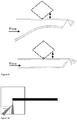
- Figure 6 illustrates a fifth example defining a multi-orifice plate 4 chamber printhead 1 design using external fluid flow 5 to direct deposition.
- Gas flow is applied to the dispense orifice via the chamber 3 to create an air flow that reduces the spread of the dispensed fluid such that the resolution of the deposited fluid features is increased.
- the velocity of the air flow can be controlled to achieve the desired resolution, and it is possible to use the air flow to direct the dispensed fluids.
- a sixth unclaimed example defines flow channels with perpendicular piezoactuators to control deposition width.
- Figure 7 illustrates a seventh unclaimed example defining flow channel cross-sections to minimise movement perpendicular to the excitation direction.
- Known in the art is circular cross section flow channels for piezo-actuated liquid deposition. These cross sections, while suitable for the purpose of liquid transport do not eliminate off axis (the axis defined as the plane parallel to the piezo actuator and nozzle tip) vibrational modes of excitation. These off axis vibrations can limit precision of the droplet formation and hence the resolution of the deposited materials.
- This example refers to non-circular cross sections, which enable mechanical control of the piezo-actuator excitation such that off-axis movement is minimised.
- We refer in this invention specifically to oval, square, triangular section flow channels and variations therein, which are intrinsically stiffer in off axis directions than a circular cross section of comparable wall thickness.
- Figure 8 illustrates an eighth unclaimed example defining an interdigitated array of dispenser flow channels 2.
- An array of needles that is interdigitated with an opposing array of needles, where the resolution is doubled by adding the opposing row of needles.
- the arrays are controlled by the same software signals, enabling a higher resolution image to be created.
- Figure 9 illustrates a ninth unclaimed example defining tapered flow channel cross-sections for high viscosity fluids.
- the cross sectional area reduction is designed to minimise the flow resistance of the tube such that higher viscosity fluids can be transported using the same outlet orifice dimensions.
- This design is based on the concept that the flow channel is tapered to allow both reduced flow resistance and maintain the required outlet geometry for piezo-actuated liquid deposition to occur. It is known that an outlet geometry with a larger cross sectional area does not enable piezo actuated liquid deposition.
- a further example of this concept utilises a constriction of the orifice cross section itself to minimise area of the meniscus, such that statistical variation of the meniscus geometry is minimised.
- a tenth unclaimed example defines a rifled flow channel to reduce resistance to flow in the channel.
- Figure 10 illustrates an eleventh unclaimed example defining a continuous flow configuration for high viscosity fluids.
- the chamber 3 includes an area of the nozzle plate 4 that is connected back to the ink system via a recirculating pump.
- the dispensed ink flow can be redirected to dispense via one of the following mechanisms: i) air flow; ii) piezo; iii) electrostatic.
Landscapes
- Particle Formation And Scattering Control In Inkjet Printers (AREA)
- Coating Apparatus (AREA)
Description
- The present invention relates to an industrial printhead particularly in the form of a configuration of piezoactuated flow channel depositors to form an array that can be used industrially as a reliable high resolution digital printhead for high viscosity fluids.
- Printheads including piezo actuated flow channel depositors for the deposition of fluids are known.
JP2008-126584 - Piezoactuated needles are known to be useful for the deposition of fluids based on the mechanism described in
PCT/HU1999/000015 - In this patent we describe a printhead design that overcomes the industrial limitations of the invention described in
PCT/HU1999/000015 - 1. Enclosure of the dispensing nozzle in a compartment including a gaseous flow field to: maintain solvent vapour pressure (to minimise evaporation); control dispensed fluid characteristics (direction, droplet size etc.); minimise effect of proximate airflows on dispenser performance
- 2. A mechanical mechanism to maintain the nozzle condition to minimise clogging and material build-up
- 3. A development of the flow channel design described in
PCT/HU1999/000015 - 4. A mechanism to deflect and recirculate the dispensed fluid if its deposition is not required (in continuous flow mode)
- We describe the invention of an industrial printhead configuration that overcomes the limitations of the configuration described in
PCT/HU1999/000015 - An aspect of the invention provides an industrial printhead comprising a fluid being dispensed and an array of piezoactuated flow channel dispensers each of which has an orifice with a nozzle tip to allow exit of the fluid being dispensed, the piezoactuated flow channel dispensers being enclosed in a chamber with a multi-orifice plate, the printhead comprising a fluid which fills the chamber, wherein the fluid composition in the chamber is at the saturated vapour of the fluid being dispensed to minimise evaporation of the fluid being dispensed at the nozzle tip.
- Configuration of piezoactuated flow channel depositors to form an array that can be used industrially as a reliable high resolution digital printhead for high viscosity fluids. In order to implement piezoactuated flow channels depositors for reliable industrial use at a suitable resolution for coding and marking and with a wide range of fluids, including high viscosity, several limitations were overcome with the disclosed printhead design that achieve the following improvements: i) Minimising clogging of the dispenser orifices; ii) Increasing the achievable resolution to > 5 dpi; iii) Dispensing high viscosity fluids > 1000 cposie.
-
-
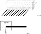
Figure 1 shows a 3D View of a Printhead design according to aspects of the invention; -
Figure 2 shows an example of a multi-orifice plate chamber printhead design saturated solvent vapour in dispenser chamber; -
Figure 3 shows a plan view of a multiple orifice nozzle plate design; -
Figure 4 shows a side view of a rotating brush nozzle cleaner; -
Figure 5 shows a heated nozzle tip to control meniscus and droplet formation; -
Figure 6 shows of external to focus deposited fluids; -
Figure 7 shows cross-sections of the flow channel to minimise off-axis movement; -
Figure 8 shows an ilnterdigitated array of dispenser nozzles to achieve a high resolution printhead configuration. Left - non-overlapped nozzle plate orifices. Right overlapped nozzle plate orifices; -
Figure 9 shows tapered flow channels to reduce flow resistance to high viscosity fluids;Figure 10 shows piezo re-directed fluids flow. - The printhead 1 design described includes an array of flow channels 2 entering a gas-filled chamber 3 that encapsulates the flow channel orifices and acts to manage the fluids that exit the flow channel such that they can be deposited onto a substrate more reliably, at higher resolution and using higher viscosity fluids than an array of flow channels 2 alone.
- The chamber 3 design is at the core of this invention and comprises a gas filled headspace, an array of secondary orifices and a means to insert the flow channels 2 into the chamber 3. A key element of the invention is the geometry of the chamber 3 and the position of the flow channels 2 relative to the chamber nozzle plate orifices and internal structures to direct gas flow in the chamber 3.
-
Figures 2 and3 illustrate a first example defining a chamber 3 filled with solventsaturated vapour: a) the flow channel enclosure 3 is filled with gas to create a solvent saturated environment; b) the flow channel 2 dispense orifice is maintained in an environment of the solvent at saturated vapour pressure, therefore evaporation at the tip in minimised and clogging due to evaporation of the deposition solution solvent is also minimised; c) the saturated gas is introduced into the chamber 3 as a continuous flow; and d) the flow of gas may also direct the dispensed fluid. -
Figure 4 illustrates a second unclaimed example defining a nozzle cleaning system comprising a rotating brush assembly within a nozzle enclosure. The brush is designed to be brought into contact with the nozzle tip periodically to remove material build-up. -
Figure 5 illustrates a third unclaimed example defining a locally heated nozzle. Heated nozzle tips to minimise material build-up at the nozzle. A resistive heating element is integrated with the flow channel to deliver a locally increased temperature at the nozzle tip. Piezo- actuated liquid deposition is based on breaking the surface tension of a liquid using high shear forces at a needle orifice. Control of the surface tension is therefore, a key element in achieving consistent deposition of liquids. - Since surface tension is a function of temperature and generally decreases with increasing temperature, the temperature at which the high shear droplet formation process occurs is found to be important. In this invention we describe a design in which the temperature of the tip of the needle is locally controlled in order to provide localised control of the surface tension of the liquid without changing the the liquid bulk temperature.
- The bulk temperature of the fluid can be controlled, however for many materials it is not desirable to use elevated temperatures due to materials stability.
- This invention is also capable of delivering localised heating such that thermal evaporation may occur alongside high shear droplet formation to create an additional process for droplet formation at the orifice.
- A fourth unclaimed example defines a piezo pulse pattern to remove excess fluid from the nozzle tip. A high amplitude pulse (xx Hz, yy V) that causes the material build-up at the nozzle tip to be removed.
-
Figure 6 illustrates a fifth example defining a multi-orifice plate 4 chamber printhead 1 design using external fluid flow 5 to direct deposition. Gas flow is applied to the dispense orifice via the chamber 3 to create an air flow that reduces the spread of the dispensed fluid such that the resolution of the deposited fluid features is increased. The velocity of the air flow can be controlled to achieve the desired resolution, and it is possible to use the air flow to direct the dispensed fluids. - A sixth unclaimed example defines flow channels with perpendicular piezoactuators to control deposition width. Flow channels actuated by a multiplicity of piezoactuators attached to the needle, in the preferred embodiment there are two piezoactuators attached perpendicular to the flow channel, enabling control of the flow channel perpendicular to the direction of the substrate onto which fluids are being deposited.
- This enables several elements of resolution control to be achieved fixed offsets perpendicular to the substrate travel direction of individual nozzles in an array; oscillation perpendicular to the substrate travel direction.
-
Figure 7 illustrates a seventh unclaimed example defining flow channel cross-sections to minimise movement perpendicular to the excitation direction. Known in the art is circular cross section flow channels for piezo-actuated liquid deposition. These cross sections, while suitable for the purpose of liquid transport do not eliminate off axis (the axis defined as the plane parallel to the piezo actuator and nozzle tip) vibrational modes of excitation. These off axis vibrations can limit precision of the droplet formation and hence the resolution of the deposited materials. - This example refers to non-circular cross sections, which enable mechanical control of the piezo-actuator excitation such that off-axis movement is minimised. We refer in this invention specifically to oval, square, triangular section flow channels and variations therein, which are intrinsically stiffer in off axis directions than a circular cross section of comparable wall thickness.
-
Figure 8 illustrates an eighth unclaimed example defining an interdigitated array of dispenser flow channels 2. An array of needles that is interdigitated with an opposing array of needles, where the resolution is doubled by adding the opposing row of needles. The arrays are controlled by the same software signals, enabling a higher resolution image to be created. -
Figure 9 illustrates a ninth unclaimed example defining tapered flow channel cross-sections for high viscosity fluids. Description: A piezo driven needle, wherein the flow channel reduces in cross sectional area from inlet to outlet. The cross sectional area reduction is designed to minimise the flow resistance of the tube such that higher viscosity fluids can be transported using the same outlet orifice dimensions. - Known in the art is a single piezo-actuated flow channel with constant cross sectional area. However, the fluids that can be transported by this design are limited in viscosity by the overall flow resistance of the channel, which is determined by the cross-sectional geometry required at the outlet for the piezo actuation liquid deposition process to occur. It is known that the channel is filled via capillary flow and that the pressure required is inversely proportional to channel diameter to the third power. Hence it is desirable to reduce the channels flow resistance to enable high viscosity liquids to be transported by capillary flow.
- This design is based on the concept that the flow channel is tapered to allow both reduced flow resistance and maintain the required outlet geometry for piezo-actuated liquid deposition to occur. It is known that an outlet geometry with a larger cross sectional area does not enable piezo actuated liquid deposition.
- A further example of this concept utilises a constriction of the orifice cross section itself to minimise area of the meniscus, such that statistical variation of the meniscus geometry is minimised.
- A tenth unclaimed example defines a rifled flow channel to reduce resistance to flow in the channel.
-
Figure 10 illustrates an eleventh unclaimed example defining a continuous flow configuration for high viscosity fluids. The chamber 3 includes an area of the nozzle plate 4 that is connected back to the ink system via a recirculating pump. The dispensed ink flow can be redirected to dispense via one of the following mechanisms: i) air flow; ii) piezo; iii) electrostatic.
Claims (2)
- An industrial printhead (1) comprising a fluid being dispensed and an array of piezoactuated flow channel dispensers (2) each of which has an orifice with a nozzle tip to allow exit of the fluid being dispensed, the piezoactuated flow channel dispensers being enclosed in a chamber (3) with a multi-orifice plate (4), and the printhead (1) comprising a fluid which fills the chamber (3), wherein the fluid composition in the chamber is at the saturated vapour of the fluid being dispensed to minimise evaporation of the fluid being dispensed at the nozzle tip.
- An industrial printhead (1) according to claim 1, wherein the fluid in the chamber (3) is directed parallel to the deposited fluid flow (5) to minimise spreading of the deposited fluid flow.
Priority Applications (2)
| Application Number | Priority Date | Filing Date | Title |
|---|---|---|---|
| EP21208936.1A EP3995313A3 (en) | 2016-04-25 | 2017-04-25 | Industrial printhead |
| PL17721799T PL3448684T3 (en) | 2016-04-25 | 2017-04-25 | Industrial printhead |
Applications Claiming Priority (2)
| Application Number | Priority Date | Filing Date | Title |
|---|---|---|---|
| GB1607165.6A GB2549720A (en) | 2016-04-25 | 2016-04-25 | Industrial printhead |
| PCT/GB2017/051145 WO2017187153A1 (en) | 2016-04-25 | 2017-04-25 | Industrial printhead |
Related Child Applications (1)
| Application Number | Title | Priority Date | Filing Date |
|---|---|---|---|
| EP21208936.1A Division EP3995313A3 (en) | 2016-04-25 | 2017-04-25 | Industrial printhead |
Publications (2)
| Publication Number | Publication Date |
|---|---|
| EP3448684A1 EP3448684A1 (en) | 2019-03-06 |
| EP3448684B1 true EP3448684B1 (en) | 2021-12-15 |
Family
ID=58671722
Family Applications (2)
| Application Number | Title | Priority Date | Filing Date |
|---|---|---|---|
| EP21208936.1A Withdrawn EP3995313A3 (en) | 2016-04-25 | 2017-04-25 | Industrial printhead |
| EP17721799.9A Active EP3448684B1 (en) | 2016-04-25 | 2017-04-25 | Industrial printhead |
Family Applications Before (1)
| Application Number | Title | Priority Date | Filing Date |
|---|---|---|---|
| EP21208936.1A Withdrawn EP3995313A3 (en) | 2016-04-25 | 2017-04-25 | Industrial printhead |
Country Status (10)
| Country | Link |
|---|---|
| US (2) | US11077661B2 (en) |
| EP (2) | EP3995313A3 (en) |
| CN (1) | CN109328139B (en) |
| DK (1) | DK3448684T3 (en) |
| ES (1) | ES2903289T3 (en) |
| GB (1) | GB2549720A (en) |
| HU (1) | HUE058797T2 (en) |
| PL (1) | PL3448684T3 (en) |
| PT (1) | PT3448684T (en) |
| WO (1) | WO2017187153A1 (en) |
Families Citing this family (4)
| Publication number | Priority date | Publication date | Assignee | Title |
|---|---|---|---|---|
| GB201905015D0 (en) * | 2019-04-09 | 2019-05-22 | Alchemie Tech Ltd | Improvements in or relating to industrial fluid dispensing |
| GB201905021D0 (en) * | 2019-04-09 | 2019-05-22 | Alchemie Tech Ltd | Improvements in or relating to industrial textile dyeing |
| GB2601467A (en) | 2020-08-21 | 2022-06-08 | Alchemie Tech Limited | Improvements in or relating to filters |
| CN118991243A (en) * | 2023-05-17 | 2024-11-22 | 杭州宏华数码科技股份有限公司 | Jet printing apparatus and jet printing method |
Family Cites Families (26)
| Publication number | Priority date | Publication date | Assignee | Title |
|---|---|---|---|---|
| US3667678A (en) * | 1970-03-13 | 1972-06-06 | Ibm | Nozzle structure for jet printers |
| SE7905836L (en) * | 1978-07-07 | 1980-01-08 | Dennison Mfg Co | HEAVY UNIT |
| JPS55146774A (en) | 1979-05-04 | 1980-11-15 | Nec Corp | Ink-jet recording device |
| DE3104077A1 (en) * | 1981-02-06 | 1982-09-09 | Philips Patentverwaltung Gmbh, 2000 Hamburg | "WRITING HEAD FOR INK JET PRINTER" |
| US4672397A (en) * | 1983-08-31 | 1987-06-09 | Nec Corporation | On-demand type ink-jet print head having an air flow path |
| DE4128590A1 (en) | 1991-08-28 | 1993-03-04 | Kumag Ag | METHOD FOR APPLYING PRINT INK AND SUITABLE PRINT HEAD |
| JP3715996B2 (en) * | 1994-07-29 | 2005-11-16 | 株式会社日立製作所 | Liquid crystal display device |
| US5798774A (en) * | 1996-02-28 | 1998-08-25 | Dataproducts Corporation | Gas assisted ink jet apparatus and method |
| US6065825A (en) * | 1997-11-13 | 2000-05-23 | Eastman Kodak Company | Printer having mechanically-assisted ink droplet separation and method of using same |
| HUP9800508A1 (en) * | 1998-03-09 | 2000-02-28 | György Hegedűs | Device for vibratory dispensing of liquid |
| US6976639B2 (en) | 2001-10-29 | 2005-12-20 | Edc Biosystems, Inc. | Apparatus and method for droplet steering |
| KR100446634B1 (en) * | 2002-10-15 | 2004-09-04 | 삼성전자주식회사 | Inkjet printhead and manufacturing method thereof |
| CA2575733A1 (en) * | 2003-07-31 | 2005-02-03 | Nissim Einat | Ink jet printing method and apparatus |
| EP1514685B1 (en) * | 2003-09-10 | 2007-01-24 | Fuji Photo Film Co., Ltd. | Liquid discharge apparatus and inkjet recording apparatus |
| DE10353112B4 (en) * | 2003-11-12 | 2006-12-28 | Metec Ingenieur-Ag | Printhead and its use |
| ITRE20040106A1 (en) * | 2004-09-08 | 2004-12-08 | Sacmi | METHOD AND PLANT FOR THE DECORATION OF CERAMIC TILES |
| JP2008126584A (en) | 2006-11-22 | 2008-06-05 | Canon Inc | Inkjet device |
| US7766462B2 (en) * | 2007-02-21 | 2010-08-03 | Hewlett-Packard Development Company, L.P. | Method for forming a fluid ejection device |
| ITRE20080065A1 (en) * | 2008-07-09 | 2010-01-10 | Sacmi | '' METHOD AND DEVICE FOR THE CONTROLLED DELIVERY OF COLORED SUBSTANCES '' |
| FR2937884A1 (en) * | 2008-11-05 | 2010-05-07 | Osmooze | PROCESS FOR FORMING EMULSION FROM NON-MISCIBLE LIQUIDS IN THEM AND APPLICATION TO LIQUID SUPPLY OF A NEBULIZATION DEVICE |
| JP2011201090A (en) | 2010-03-24 | 2011-10-13 | Seiko Epson Corp | Liquid ejection head, liquid ejection head unit and liquid ejector |
| WO2012175593A1 (en) * | 2011-06-24 | 2012-12-27 | Oce-Technologies B.V. | Inkjet print head |
| JP2013035742A (en) * | 2011-07-08 | 2013-02-21 | Sumitomo Electric Ind Ltd | Apparatus and method for drawing optical fiber |
| EP2849692A1 (en) * | 2012-05-14 | 2015-03-25 | Eyenovia, Inc. | Laminar flow droplet generator device and methods of use |
| WO2014007814A1 (en) * | 2012-07-03 | 2014-01-09 | Hewlett-Packard Development Company, L.P. | Fluid ejection apparatus |
| RO130415B1 (en) * | 2014-01-29 | 2019-06-28 | Sandor Szente | Funnel |
-
2016
- 2016-04-25 GB GB1607165.6A patent/GB2549720A/en not_active Withdrawn
-
2017
- 2017-04-25 PL PL17721799T patent/PL3448684T3/en unknown
- 2017-04-25 PT PT177217999T patent/PT3448684T/en unknown
- 2017-04-25 ES ES17721799T patent/ES2903289T3/en active Active
- 2017-04-25 CN CN201780038855.5A patent/CN109328139B/en active Active
- 2017-04-25 WO PCT/GB2017/051145 patent/WO2017187153A1/en not_active Ceased
- 2017-04-25 US US16/096,142 patent/US11077661B2/en active Active
- 2017-04-25 DK DK17721799.9T patent/DK3448684T3/en active
- 2017-04-25 HU HUE17721799A patent/HUE058797T2/en unknown
- 2017-04-25 EP EP21208936.1A patent/EP3995313A3/en not_active Withdrawn
- 2017-04-25 EP EP17721799.9A patent/EP3448684B1/en active Active
-
2021
- 2021-07-09 US US17/371,361 patent/US20210331469A1/en not_active Abandoned
Non-Patent Citations (1)
| Title |
|---|
| None * |
Also Published As
| Publication number | Publication date |
|---|---|
| EP3995313A2 (en) | 2022-05-11 |
| ES2903289T3 (en) | 2022-03-31 |
| US11077661B2 (en) | 2021-08-03 |
| EP3448684A1 (en) | 2019-03-06 |
| GB2549720A (en) | 2017-11-01 |
| HUE058797T2 (en) | 2022-09-28 |
| US20190134979A1 (en) | 2019-05-09 |
| PL3448684T3 (en) | 2022-02-28 |
| CN109328139A (en) | 2019-02-12 |
| US20210331469A1 (en) | 2021-10-28 |
| PT3448684T (en) | 2022-01-12 |
| CN109328139B (en) | 2021-01-15 |
| WO2017187153A1 (en) | 2017-11-02 |
| DK3448684T3 (en) | 2022-01-17 |
| EP3995313A3 (en) | 2022-07-27 |
Similar Documents
| Publication | Publication Date | Title |
|---|---|---|
| US20210331469A1 (en) | Industrial printhead | |
| US7914109B2 (en) | Liquid drop dispenser with movable deflector | |
| US7914121B2 (en) | Liquid drop dispenser with movable deflector | |
| US8042916B2 (en) | Micromachined fluid ejector array | |
| US20030169315A1 (en) | Micro Fluid Dispensers using Flexible Hollow Glass Fibers | |
| US8770722B2 (en) | Functional liquid deposition using continuous liquid | |
| EP3270981B1 (en) | System and method for dispensing material | |
| CN100339219C (en) | liquid jet head | |
| WO1995010415A1 (en) | Fluid dispenser | |
| US8974041B2 (en) | Droplet selection mechanism | |
| CN113117918A (en) | Fluid injector | |
| JP2009538225A (en) | System and method for droplet ejection | |
| HK40002129B (en) | Industrial printhead | |
| JP7604479B2 (en) | Method and apparatus for dispensing droplets of liquid - Patents.com | |
| US20140022308A1 (en) | Liquid dispenser including passive pre-stressed flexible membrane | |
| US8783804B2 (en) | Functional liquid deposition using continuous liquid dispenser | |
| CN108906350A (en) | A kind of segment injector for precision equipment | |
| CN208944385U (en) | A segmented nozzle for precision equipment | |
| EP3468801B1 (en) | Fluid ejection device | |
| CN202862812U (en) | Liquid jet apparatus and ink jet printer | |
| JP2004195848A (en) | Inkjet head |
Legal Events
| Date | Code | Title | Description |
|---|---|---|---|
| STAA | Information on the status of an ep patent application or granted ep patent |
Free format text: STATUS: UNKNOWN |
|
| STAA | Information on the status of an ep patent application or granted ep patent |
Free format text: STATUS: THE INTERNATIONAL PUBLICATION HAS BEEN MADE |
|
| PUAI | Public reference made under article 153(3) epc to a published international application that has entered the european phase |
Free format text: ORIGINAL CODE: 0009012 |
|
| STAA | Information on the status of an ep patent application or granted ep patent |
Free format text: STATUS: REQUEST FOR EXAMINATION WAS MADE |
|
| 17P | Request for examination filed |
Effective date: 20181120 |
|
| AK | Designated contracting states |
Kind code of ref document: A1 Designated state(s): AL AT BE BG CH CY CZ DE DK EE ES FI FR GB GR HR HU IE IS IT LI LT LU LV MC MK MT NL NO PL PT RO RS SE SI SK SM TR |
|
| AX | Request for extension of the european patent |
Extension state: BA ME |
|
| DAV | Request for validation of the european patent (deleted) | ||
| DAX | Request for extension of the european patent (deleted) | ||
| REG | Reference to a national code |
Ref country code: HK Ref legal event code: DE Ref document number: 40002129 Country of ref document: HK |
|
| STAA | Information on the status of an ep patent application or granted ep patent |
Free format text: STATUS: EXAMINATION IS IN PROGRESS |
|
| 17Q | First examination report despatched |
Effective date: 20200616 |
|
| GRAP | Despatch of communication of intention to grant a patent |
Free format text: ORIGINAL CODE: EPIDOSNIGR1 |
|
| STAA | Information on the status of an ep patent application or granted ep patent |
Free format text: STATUS: GRANT OF PATENT IS INTENDED |
|
| INTG | Intention to grant announced |
Effective date: 20210621 |
|
| GRAS | Grant fee paid |
Free format text: ORIGINAL CODE: EPIDOSNIGR3 |
|
| GRAA | (expected) grant |
Free format text: ORIGINAL CODE: 0009210 |
|
| STAA | Information on the status of an ep patent application or granted ep patent |
Free format text: STATUS: THE PATENT HAS BEEN GRANTED |
|
| AK | Designated contracting states |
Kind code of ref document: B1 Designated state(s): AL AT BE BG CH CY CZ DE DK EE ES FI FR GB GR HR HU IE IS IT LI LT LU LV MC MK MT NL NO PL PT RO RS SE SI SK SM TR |
|
| RAP3 | Party data changed (applicant data changed or rights of an application transferred) |
Owner name: JETRONICA LIMITED |
|
| REG | Reference to a national code |
Ref country code: GB Ref legal event code: FG4D Ref country code: CH Ref legal event code: EP |
|
| REG | Reference to a national code |
Ref country code: IE Ref legal event code: FG4D Ref country code: DE Ref legal event code: R096 Ref document number: 602017050921 Country of ref document: DE |
|
| REG | Reference to a national code |
Ref country code: FI Ref legal event code: FGE |
|
| REG | Reference to a national code |
Ref country code: PT Ref legal event code: SC4A Ref document number: 3448684 Country of ref document: PT Date of ref document: 20220112 Kind code of ref document: T Free format text: AVAILABILITY OF NATIONAL TRANSLATION Effective date: 20220106 |
|
| REG | Reference to a national code |
Ref country code: AT Ref legal event code: REF Ref document number: 1455202 Country of ref document: AT Kind code of ref document: T Effective date: 20220115 |
|
| REG | Reference to a national code |
Ref country code: DK Ref legal event code: T3 Effective date: 20220110 |
|
| REG | Reference to a national code |
Ref country code: SE Ref legal event code: TRGR |
|
| REG | Reference to a national code |
Ref country code: NL Ref legal event code: FP |
|
| REG | Reference to a national code |
Ref country code: NO Ref legal event code: T2 Effective date: 20211215 |
|
| REG | Reference to a national code |
Ref country code: ES Ref legal event code: FG2A Ref document number: 2903289 Country of ref document: ES Kind code of ref document: T3 Effective date: 20220331 |
|
| REG | Reference to a national code |
Ref country code: LT Ref legal event code: MG9D |
|
| PG25 | Lapsed in a contracting state [announced via postgrant information from national office to epo] |
Ref country code: RS Free format text: LAPSE BECAUSE OF FAILURE TO SUBMIT A TRANSLATION OF THE DESCRIPTION OR TO PAY THE FEE WITHIN THE PRESCRIBED TIME-LIMIT Effective date: 20211215 Ref country code: LT Free format text: LAPSE BECAUSE OF FAILURE TO SUBMIT A TRANSLATION OF THE DESCRIPTION OR TO PAY THE FEE WITHIN THE PRESCRIBED TIME-LIMIT Effective date: 20211215 Ref country code: BG Free format text: LAPSE BECAUSE OF FAILURE TO SUBMIT A TRANSLATION OF THE DESCRIPTION OR TO PAY THE FEE WITHIN THE PRESCRIBED TIME-LIMIT Effective date: 20220315 |
|
| PG25 | Lapsed in a contracting state [announced via postgrant information from national office to epo] |
Ref country code: LV Free format text: LAPSE BECAUSE OF FAILURE TO SUBMIT A TRANSLATION OF THE DESCRIPTION OR TO PAY THE FEE WITHIN THE PRESCRIBED TIME-LIMIT Effective date: 20211215 Ref country code: HR Free format text: LAPSE BECAUSE OF FAILURE TO SUBMIT A TRANSLATION OF THE DESCRIPTION OR TO PAY THE FEE WITHIN THE PRESCRIBED TIME-LIMIT Effective date: 20211215 Ref country code: GR Free format text: LAPSE BECAUSE OF FAILURE TO SUBMIT A TRANSLATION OF THE DESCRIPTION OR TO PAY THE FEE WITHIN THE PRESCRIBED TIME-LIMIT Effective date: 20220316 |
|
| PG25 | Lapsed in a contracting state [announced via postgrant information from national office to epo] |
Ref country code: SM Free format text: LAPSE BECAUSE OF FAILURE TO SUBMIT A TRANSLATION OF THE DESCRIPTION OR TO PAY THE FEE WITHIN THE PRESCRIBED TIME-LIMIT Effective date: 20211215 Ref country code: SK Free format text: LAPSE BECAUSE OF FAILURE TO SUBMIT A TRANSLATION OF THE DESCRIPTION OR TO PAY THE FEE WITHIN THE PRESCRIBED TIME-LIMIT Effective date: 20211215 Ref country code: RO Free format text: LAPSE BECAUSE OF FAILURE TO SUBMIT A TRANSLATION OF THE DESCRIPTION OR TO PAY THE FEE WITHIN THE PRESCRIBED TIME-LIMIT Effective date: 20211215 Ref country code: EE Free format text: LAPSE BECAUSE OF FAILURE TO SUBMIT A TRANSLATION OF THE DESCRIPTION OR TO PAY THE FEE WITHIN THE PRESCRIBED TIME-LIMIT Effective date: 20211215 |
|
| REG | Reference to a national code |
Ref country code: DE Ref legal event code: R097 Ref document number: 602017050921 Country of ref document: DE |
|
| REG | Reference to a national code |
Ref country code: HU Ref legal event code: AG4A Ref document number: E058797 Country of ref document: HU |
|
| PG25 | Lapsed in a contracting state [announced via postgrant information from national office to epo] |
Ref country code: IS Free format text: LAPSE BECAUSE OF FAILURE TO SUBMIT A TRANSLATION OF THE DESCRIPTION OR TO PAY THE FEE WITHIN THE PRESCRIBED TIME-LIMIT Effective date: 20220415 |
|
| PLBE | No opposition filed within time limit |
Free format text: ORIGINAL CODE: 0009261 |
|
| STAA | Information on the status of an ep patent application or granted ep patent |
Free format text: STATUS: NO OPPOSITION FILED WITHIN TIME LIMIT |
|
| PG25 | Lapsed in a contracting state [announced via postgrant information from national office to epo] |
Ref country code: AL Free format text: LAPSE BECAUSE OF FAILURE TO SUBMIT A TRANSLATION OF THE DESCRIPTION OR TO PAY THE FEE WITHIN THE PRESCRIBED TIME-LIMIT Effective date: 20211215 |
|
| 26N | No opposition filed |
Effective date: 20220916 |
|
| PG25 | Lapsed in a contracting state [announced via postgrant information from national office to epo] |
Ref country code: SI Free format text: LAPSE BECAUSE OF FAILURE TO SUBMIT A TRANSLATION OF THE DESCRIPTION OR TO PAY THE FEE WITHIN THE PRESCRIBED TIME-LIMIT Effective date: 20211215 |
|
| PG25 | Lapsed in a contracting state [announced via postgrant information from national office to epo] |
Ref country code: MC Free format text: LAPSE BECAUSE OF FAILURE TO SUBMIT A TRANSLATION OF THE DESCRIPTION OR TO PAY THE FEE WITHIN THE PRESCRIBED TIME-LIMIT Effective date: 20211215 Ref country code: LU Free format text: LAPSE BECAUSE OF NON-PAYMENT OF DUE FEES Effective date: 20220425 |
|
| REG | Reference to a national code |
Ref country code: AT Ref legal event code: UEP Ref document number: 1455202 Country of ref document: AT Kind code of ref document: T Effective date: 20211215 |
|
| PGFP | Annual fee paid to national office [announced via postgrant information from national office to epo] |
Ref country code: DK Payment date: 20231030 Year of fee payment: 7 Ref country code: CZ Payment date: 20231019 Year of fee payment: 7 Ref country code: AT Payment date: 20231025 Year of fee payment: 7 Ref country code: NO Payment date: 20231101 Year of fee payment: 7 Ref country code: FR Payment date: 20231030 Year of fee payment: 7 Ref country code: FI Payment date: 20231025 Year of fee payment: 7 |
|
| PGFP | Annual fee paid to national office [announced via postgrant information from national office to epo] |
Ref country code: PL Payment date: 20231019 Year of fee payment: 7 Ref country code: BE Payment date: 20231030 Year of fee payment: 7 |
|
| PG25 | Lapsed in a contracting state [announced via postgrant information from national office to epo] |
Ref country code: MK Free format text: LAPSE BECAUSE OF FAILURE TO SUBMIT A TRANSLATION OF THE DESCRIPTION OR TO PAY THE FEE WITHIN THE PRESCRIBED TIME-LIMIT Effective date: 20211215 Ref country code: CY Free format text: LAPSE BECAUSE OF FAILURE TO SUBMIT A TRANSLATION OF THE DESCRIPTION OR TO PAY THE FEE WITHIN THE PRESCRIBED TIME-LIMIT Effective date: 20211215 |
|
| PG25 | Lapsed in a contracting state [announced via postgrant information from national office to epo] |
Ref country code: MT Free format text: LAPSE BECAUSE OF FAILURE TO SUBMIT A TRANSLATION OF THE DESCRIPTION OR TO PAY THE FEE WITHIN THE PRESCRIBED TIME-LIMIT Effective date: 20211215 |
|
| REG | Reference to a national code |
Ref country code: DK Ref legal event code: EBP Effective date: 20240430 |
|
| REG | Reference to a national code |
Ref country code: AT Ref legal event code: MM01 Ref document number: 1455202 Country of ref document: AT Kind code of ref document: T Effective date: 20240425 |
|
| REG | Reference to a national code |
Ref country code: BE Ref legal event code: MM Effective date: 20240430 |
|
| PG25 | Lapsed in a contracting state [announced via postgrant information from national office to epo] |
Ref country code: NO Free format text: LAPSE BECAUSE OF NON-PAYMENT OF DUE FEES Effective date: 20240430 |
|
| PG25 | Lapsed in a contracting state [announced via postgrant information from national office to epo] |
Ref country code: BE Free format text: LAPSE BECAUSE OF NON-PAYMENT OF DUE FEES Effective date: 20240430 Ref country code: FI Free format text: LAPSE BECAUSE OF NON-PAYMENT OF DUE FEES Effective date: 20240425 |
|
| PG25 | Lapsed in a contracting state [announced via postgrant information from national office to epo] |
Ref country code: FR Free format text: LAPSE BECAUSE OF NON-PAYMENT OF DUE FEES Effective date: 20240430 |
|
| PG25 | Lapsed in a contracting state [announced via postgrant information from national office to epo] |
Ref country code: AT Free format text: LAPSE BECAUSE OF NON-PAYMENT OF DUE FEES Effective date: 20240425 |
|
| PG25 | Lapsed in a contracting state [announced via postgrant information from national office to epo] |
Ref country code: CZ Free format text: LAPSE BECAUSE OF NON-PAYMENT OF DUE FEES Effective date: 20240425 |
|
| PG25 | Lapsed in a contracting state [announced via postgrant information from national office to epo] |
Ref country code: NO Free format text: LAPSE BECAUSE OF NON-PAYMENT OF DUE FEES Effective date: 20240430 Ref country code: FR Free format text: LAPSE BECAUSE OF NON-PAYMENT OF DUE FEES Effective date: 20240430 Ref country code: FI Free format text: LAPSE BECAUSE OF NON-PAYMENT OF DUE FEES Effective date: 20240425 Ref country code: CZ Free format text: LAPSE BECAUSE OF NON-PAYMENT OF DUE FEES Effective date: 20240425 Ref country code: BE Free format text: LAPSE BECAUSE OF NON-PAYMENT OF DUE FEES Effective date: 20240430 Ref country code: AT Free format text: LAPSE BECAUSE OF NON-PAYMENT OF DUE FEES Effective date: 20240425 |
|
| PG25 | Lapsed in a contracting state [announced via postgrant information from national office to epo] |
Ref country code: DK Free format text: LAPSE BECAUSE OF NON-PAYMENT OF DUE FEES Effective date: 20240430 |
|
| PGFP | Annual fee paid to national office [announced via postgrant information from national office to epo] |
Ref country code: NL Payment date: 20250418 Year of fee payment: 9 |
|
| PGFP | Annual fee paid to national office [announced via postgrant information from national office to epo] |
Ref country code: DE Payment date: 20250422 Year of fee payment: 9 |
|
| PGFP | Annual fee paid to national office [announced via postgrant information from national office to epo] |
Ref country code: ES Payment date: 20250530 Year of fee payment: 9 |
|
| PGFP | Annual fee paid to national office [announced via postgrant information from national office to epo] |
Ref country code: HU Payment date: 20250424 Year of fee payment: 9 |
|
| PGFP | Annual fee paid to national office [announced via postgrant information from national office to epo] |
Ref country code: IT Payment date: 20250422 Year of fee payment: 9 |
|
| PGFP | Annual fee paid to national office [announced via postgrant information from national office to epo] |
Ref country code: PT Payment date: 20250417 Year of fee payment: 9 |
|
| PGFP | Annual fee paid to national office [announced via postgrant information from national office to epo] |
Ref country code: CH Payment date: 20250501 Year of fee payment: 9 |
|
| PGFP | Annual fee paid to national office [announced via postgrant information from national office to epo] |
Ref country code: TR Payment date: 20250421 Year of fee payment: 9 |
|
| PGFP | Annual fee paid to national office [announced via postgrant information from national office to epo] |
Ref country code: IE Payment date: 20250422 Year of fee payment: 9 |
|
| PGFP | Annual fee paid to national office [announced via postgrant information from national office to epo] |
Ref country code: SE Payment date: 20250429 Year of fee payment: 9 |
|
| PG25 | Lapsed in a contracting state [announced via postgrant information from national office to epo] |
Ref country code: PL Free format text: LAPSE BECAUSE OF FAILURE TO SUBMIT A TRANSLATION OF THE DESCRIPTION OR TO PAY THE FEE WITHIN THE PRESCRIBED TIME-LIMIT Effective date: 20240425 |
|
| PG25 | Lapsed in a contracting state [announced via postgrant information from national office to epo] |
Ref country code: PL Free format text: LAPSE BECAUSE OF NON-PAYMENT OF DUE FEES Effective date: 20240425 |
|
| PGFP | Annual fee paid to national office [announced via postgrant information from national office to epo] |
Ref country code: GB Payment date: 20260319 Year of fee payment: 10 |