EP3448314B1 - Replacement heart valve with improved stitching - Google Patents
Replacement heart valve with improved stitching Download PDFInfo
- Publication number
- EP3448314B1 EP3448314B1 EP17722297.3A EP17722297A EP3448314B1 EP 3448314 B1 EP3448314 B1 EP 3448314B1 EP 17722297 A EP17722297 A EP 17722297A EP 3448314 B1 EP3448314 B1 EP 3448314B1
- Authority
- EP
- European Patent Office
- Prior art keywords
- sutures
- distal
- anchor member
- lashing
- expandable anchor
- Prior art date
- Legal status (The legal status is an assumption and is not a legal conclusion. Google has not performed a legal analysis and makes no representation as to the accuracy of the status listed.)
- Active
Links
- 210000003709 heart valve Anatomy 0.000 title claims description 32
- 239000007943 implant Substances 0.000 claims description 75
- 230000003014 reinforcing effect Effects 0.000 claims description 36
- 238000004519 manufacturing process Methods 0.000 claims description 13
- 239000000463 material Substances 0.000 description 28
- 229910001000 nickel titanium Inorganic materials 0.000 description 24
- HLXZNVUGXRDIFK-UHFFFAOYSA-N nickel titanium Chemical compound [Ti].[Ti].[Ti].[Ti].[Ti].[Ti].[Ti].[Ti].[Ti].[Ti].[Ti].[Ni].[Ni].[Ni].[Ni].[Ni].[Ni].[Ni].[Ni].[Ni].[Ni].[Ni].[Ni].[Ni].[Ni] HLXZNVUGXRDIFK-UHFFFAOYSA-N 0.000 description 16
- -1 polyethylene Polymers 0.000 description 15
- 238000004804 winding Methods 0.000 description 15
- 238000000034 method Methods 0.000 description 8
- 229910001182 Mo alloy Inorganic materials 0.000 description 7
- 238000000576 coating method Methods 0.000 description 7
- PXHVJJICTQNCMI-UHFFFAOYSA-N Nickel Chemical compound [Ni] PXHVJJICTQNCMI-UHFFFAOYSA-N 0.000 description 6
- 229910045601 alloy Inorganic materials 0.000 description 6
- 239000000956 alloy Substances 0.000 description 6
- 210000001765 aortic valve Anatomy 0.000 description 6
- 239000000203 mixture Substances 0.000 description 6
- 229920000642 polymer Polymers 0.000 description 6
- 239000004810 polytetrafluoroethylene Substances 0.000 description 5
- 229920001343 polytetrafluoroethylene Polymers 0.000 description 5
- 230000002787 reinforcement Effects 0.000 description 5
- 238000011282 treatment Methods 0.000 description 5
- 239000004952 Polyamide Substances 0.000 description 4
- 229920002614 Polyether block amide Polymers 0.000 description 4
- 239000011248 coating agent Substances 0.000 description 4
- 230000002950 deficient Effects 0.000 description 4
- 229910000856 hastalloy Inorganic materials 0.000 description 4
- BASFCYQUMIYNBI-UHFFFAOYSA-N platinum Chemical compound [Pt] BASFCYQUMIYNBI-UHFFFAOYSA-N 0.000 description 4
- 229920002647 polyamide Polymers 0.000 description 4
- 239000010935 stainless steel Substances 0.000 description 4
- 229910001220 stainless steel Inorganic materials 0.000 description 4
- 238000002560 therapeutic procedure Methods 0.000 description 4
- RTZKZFJDLAIYFH-UHFFFAOYSA-N Diethyl ether Chemical compound CCOCC RTZKZFJDLAIYFH-UHFFFAOYSA-N 0.000 description 3
- 239000004698 Polyethylene Substances 0.000 description 3
- 239000004721 Polyphenylene oxide Substances 0.000 description 3
- 239000004743 Polypropylene Substances 0.000 description 3
- 239000000853 adhesive Substances 0.000 description 3
- 230000001070 adhesive effect Effects 0.000 description 3
- 210000003484 anatomy Anatomy 0.000 description 3
- 210000000748 cardiovascular system Anatomy 0.000 description 3
- 229920001577 copolymer Polymers 0.000 description 3
- 210000004351 coronary vessel Anatomy 0.000 description 3
- 230000003247 decreasing effect Effects 0.000 description 3
- 230000000694 effects Effects 0.000 description 3
- 238000001125 extrusion Methods 0.000 description 3
- 229920001903 high density polyethylene Polymers 0.000 description 3
- 239000004700 high-density polyethylene Substances 0.000 description 3
- 238000002595 magnetic resonance imaging Methods 0.000 description 3
- 229910052751 metal Inorganic materials 0.000 description 3
- 239000002184 metal Substances 0.000 description 3
- 239000007769 metal material Substances 0.000 description 3
- 229910052759 nickel Inorganic materials 0.000 description 3
- 229920000573 polyethylene Polymers 0.000 description 3
- 229920000139 polyethylene terephthalate Polymers 0.000 description 3
- 239000005020 polyethylene terephthalate Substances 0.000 description 3
- 229920001155 polypropylene Polymers 0.000 description 3
- 239000004814 polyurethane Substances 0.000 description 3
- 229920002635 polyurethane Polymers 0.000 description 3
- 230000008439 repair process Effects 0.000 description 3
- 210000005166 vasculature Anatomy 0.000 description 3
- 229910000881 Cu alloy Inorganic materials 0.000 description 2
- 239000004812 Fluorinated ethylene propylene Substances 0.000 description 2
- 229920000339 Marlex Polymers 0.000 description 2
- KDLHZDBZIXYQEI-UHFFFAOYSA-N Palladium Chemical compound [Pd] KDLHZDBZIXYQEI-UHFFFAOYSA-N 0.000 description 2
- 239000004696 Poly ether ether ketone Substances 0.000 description 2
- 239000004697 Polyetherimide Substances 0.000 description 2
- 239000004642 Polyimide Substances 0.000 description 2
- 239000004734 Polyphenylene sulfide Substances 0.000 description 2
- RTAQQCXQSZGOHL-UHFFFAOYSA-N Titanium Chemical compound [Ti] RTAQQCXQSZGOHL-UHFFFAOYSA-N 0.000 description 2
- 229910001080 W alloy Inorganic materials 0.000 description 2
- MTHLBYMFGWSRME-UHFFFAOYSA-N [Cr].[Co].[Mo] Chemical compound [Cr].[Co].[Mo] MTHLBYMFGWSRME-UHFFFAOYSA-N 0.000 description 2
- 238000004458 analytical method Methods 0.000 description 2
- 229910001566 austenite Inorganic materials 0.000 description 2
- 238000005452 bending Methods 0.000 description 2
- 230000008901 benefit Effects 0.000 description 2
- 239000000788 chromium alloy Substances 0.000 description 2
- PRQRQKBNBXPISG-UHFFFAOYSA-N chromium cobalt molybdenum nickel Chemical compound [Cr].[Co].[Ni].[Mo] PRQRQKBNBXPISG-UHFFFAOYSA-N 0.000 description 2
- YOCUPQPZWBBYIX-UHFFFAOYSA-N copper nickel Chemical compound [Ni].[Cu] YOCUPQPZWBBYIX-UHFFFAOYSA-N 0.000 description 2
- 238000000113 differential scanning calorimetry Methods 0.000 description 2
- 229910000701 elgiloys (Co-Cr-Ni Alloy) Inorganic materials 0.000 description 2
- 150000002148 esters Chemical class 0.000 description 2
- 229920000840 ethylene tetrafluoroethylene copolymer Polymers 0.000 description 2
- 239000000945 filler Substances 0.000 description 2
- 230000006870 function Effects 0.000 description 2
- 229920001477 hydrophilic polymer Polymers 0.000 description 2
- 229910000734 martensite Inorganic materials 0.000 description 2
- 229910001092 metal group alloy Inorganic materials 0.000 description 2
- 238000012986 modification Methods 0.000 description 2
- 230000004048 modification Effects 0.000 description 2
- DDTIGTPWGISMKL-UHFFFAOYSA-N molybdenum nickel Chemical compound [Ni].[Mo] DDTIGTPWGISMKL-UHFFFAOYSA-N 0.000 description 2
- 239000004745 nonwoven fabric Substances 0.000 description 2
- 229920009441 perflouroethylene propylene Polymers 0.000 description 2
- 229910052697 platinum Inorganic materials 0.000 description 2
- 229920001200 poly(ethylene-vinyl acetate) Polymers 0.000 description 2
- 229920002492 poly(sulfone) Polymers 0.000 description 2
- 229920001707 polybutylene terephthalate Polymers 0.000 description 2
- 239000004417 polycarbonate Substances 0.000 description 2
- 229920000515 polycarbonate Polymers 0.000 description 2
- 229920000728 polyester Polymers 0.000 description 2
- 229920002530 polyetherether ketone Polymers 0.000 description 2
- 229920001601 polyetherimide Polymers 0.000 description 2
- 229920001721 polyimide Polymers 0.000 description 2
- 229920006324 polyoxymethylene Polymers 0.000 description 2
- 229920006380 polyphenylene oxide Polymers 0.000 description 2
- 229920000069 polyphenylene sulfide Polymers 0.000 description 2
- 229920001296 polysiloxane Polymers 0.000 description 2
- 239000004800 polyvinyl chloride Substances 0.000 description 2
- 230000009467 reduction Effects 0.000 description 2
- 239000004753 textile Substances 0.000 description 2
- 239000010936 titanium Substances 0.000 description 2
- 229910052719 titanium Inorganic materials 0.000 description 2
- 238000011144 upstream manufacturing Methods 0.000 description 2
- 239000002759 woven fabric Substances 0.000 description 2
- KHXKESCWFMPTFT-UHFFFAOYSA-N 1,1,1,2,2,3,3-heptafluoro-3-(1,2,2-trifluoroethenoxy)propane Chemical compound FC(F)=C(F)OC(F)(F)C(F)(F)C(F)(F)F KHXKESCWFMPTFT-UHFFFAOYSA-N 0.000 description 1
- 241000283690 Bos taurus Species 0.000 description 1
- 229910000531 Co alloy Inorganic materials 0.000 description 1
- 229920004943 Delrin® Polymers 0.000 description 1
- 229920006055 Durethan® Polymers 0.000 description 1
- 239000004593 Epoxy Substances 0.000 description 1
- 229920000219 Ethylene vinyl alcohol Polymers 0.000 description 1
- 229910000640 Fe alloy Inorganic materials 0.000 description 1
- 229920003620 Grilon® Polymers 0.000 description 1
- 229910000787 Gum metal Inorganic materials 0.000 description 1
- DGAQECJNVWCQMB-PUAWFVPOSA-M Ilexoside XXIX Chemical compound C[C@@H]1CC[C@@]2(CC[C@@]3(C(=CC[C@H]4[C@]3(CC[C@@H]5[C@@]4(CC[C@@H](C5(C)C)OS(=O)(=O)[O-])C)C)[C@@H]2[C@]1(C)O)C)C(=O)O[C@H]6[C@@H]([C@H]([C@@H]([C@H](O6)CO)O)O)O.[Na+] DGAQECJNVWCQMB-PUAWFVPOSA-M 0.000 description 1
- 229920000271 Kevlar® Polymers 0.000 description 1
- JHWNWJKBPDFINM-UHFFFAOYSA-N Laurolactam Chemical compound O=C1CCCCCCCCCCCN1 JHWNWJKBPDFINM-UHFFFAOYSA-N 0.000 description 1
- 229910001209 Low-carbon steel Inorganic materials 0.000 description 1
- 229910000792 Monel Inorganic materials 0.000 description 1
- 229910000990 Ni alloy Inorganic materials 0.000 description 1
- 239000004677 Nylon Substances 0.000 description 1
- 229920000299 Nylon 12 Polymers 0.000 description 1
- 229930040373 Paraformaldehyde Natural products 0.000 description 1
- 229920000265 Polyparaphenylene Polymers 0.000 description 1
- 239000004793 Polystyrene Substances 0.000 description 1
- QXZUUHYBWMWJHK-UHFFFAOYSA-N [Co].[Ni] Chemical compound [Co].[Ni] QXZUUHYBWMWJHK-UHFFFAOYSA-N 0.000 description 1
- HZEWFHLRYVTOIW-UHFFFAOYSA-N [Ti].[Ni] Chemical compound [Ti].[Ni] HZEWFHLRYVTOIW-UHFFFAOYSA-N 0.000 description 1
- 229920000615 alginic acid Polymers 0.000 description 1
- 235000010443 alginic acid Nutrition 0.000 description 1
- 230000004075 alteration Effects 0.000 description 1
- 238000002399 angioplasty Methods 0.000 description 1
- 210000002376 aorta thoracic Anatomy 0.000 description 1
- 238000013459 approach Methods 0.000 description 1
- 229920000249 biocompatible polymer Polymers 0.000 description 1
- 210000004204 blood vessel Anatomy 0.000 description 1
- 230000036760 body temperature Effects 0.000 description 1
- 239000007767 bonding agent Substances 0.000 description 1
- 150000001720 carbohydrates Chemical class 0.000 description 1
- 239000000919 ceramic Substances 0.000 description 1
- OGSYQYXYGXIQFH-UHFFFAOYSA-N chromium molybdenum nickel Chemical compound [Cr].[Ni].[Mo] OGSYQYXYGXIQFH-UHFFFAOYSA-N 0.000 description 1
- 230000000295 complement effect Effects 0.000 description 1
- 239000002131 composite material Substances 0.000 description 1
- 150000001875 compounds Chemical class 0.000 description 1
- 238000013461 design Methods 0.000 description 1
- 201000010099 disease Diseases 0.000 description 1
- 208000037265 diseases, disorders, signs and symptoms Diseases 0.000 description 1
- 239000013013 elastic material Substances 0.000 description 1
- 229920001971 elastomer Polymers 0.000 description 1
- 239000000806 elastomer Substances 0.000 description 1
- 229920006351 engineering plastic Polymers 0.000 description 1
- JBKVHLHDHHXQEQ-UHFFFAOYSA-N epsilon-caprolactam Chemical compound O=C1CCCCCN1 JBKVHLHDHHXQEQ-UHFFFAOYSA-N 0.000 description 1
- QHSJIZLJUFMIFP-UHFFFAOYSA-N ethene;1,1,2,2-tetrafluoroethene Chemical group C=C.FC(F)=C(F)F QHSJIZLJUFMIFP-UHFFFAOYSA-N 0.000 description 1
- HQQADJVZYDDRJT-UHFFFAOYSA-N ethene;prop-1-ene Chemical group C=C.CC=C HQQADJVZYDDRJT-UHFFFAOYSA-N 0.000 description 1
- 150000002170 ethers Chemical class 0.000 description 1
- 239000005038 ethylene vinyl acetate Substances 0.000 description 1
- 239000004715 ethylene vinyl alcohol Substances 0.000 description 1
- 239000004744 fabric Substances 0.000 description 1
- 239000003302 ferromagnetic material Substances 0.000 description 1
- 239000012530 fluid Substances 0.000 description 1
- 229920002313 fluoropolymer Polymers 0.000 description 1
- 239000004811 fluoropolymer Substances 0.000 description 1
- 238000002594 fluoroscopy Methods 0.000 description 1
- PCHJSUWPFVWCPO-UHFFFAOYSA-N gold Chemical compound [Au] PCHJSUWPFVWCPO-UHFFFAOYSA-N 0.000 description 1
- 229910052737 gold Inorganic materials 0.000 description 1
- 239000010931 gold Substances 0.000 description 1
- 230000036541 health Effects 0.000 description 1
- RZXDTJIXPSCHCI-UHFFFAOYSA-N hexa-1,5-diene-2,5-diol Chemical compound OC(=C)CCC(O)=C RZXDTJIXPSCHCI-UHFFFAOYSA-N 0.000 description 1
- 230000002209 hydrophobic effect Effects 0.000 description 1
- 125000002768 hydroxyalkyl group Chemical group 0.000 description 1
- 238000003384 imaging method Methods 0.000 description 1
- 238000002513 implantation Methods 0.000 description 1
- 229910001026 inconel Inorganic materials 0.000 description 1
- 229920000554 ionomer Polymers 0.000 description 1
- UGKDIUIOSMUOAW-UHFFFAOYSA-N iron nickel Chemical compound [Fe].[Ni] UGKDIUIOSMUOAW-UHFFFAOYSA-N 0.000 description 1
- 239000004761 kevlar Substances 0.000 description 1
- 230000003902 lesion Effects 0.000 description 1
- 229920000092 linear low density polyethylene Polymers 0.000 description 1
- 239000004707 linear low-density polyethylene Substances 0.000 description 1
- 229920001684 low density polyethylene Polymers 0.000 description 1
- 239000004702 low-density polyethylene Substances 0.000 description 1
- 239000003550 marker Substances 0.000 description 1
- 230000007246 mechanism Effects 0.000 description 1
- 239000002905 metal composite material Substances 0.000 description 1
- 150000002739 metals Chemical class 0.000 description 1
- 210000004115 mitral valve Anatomy 0.000 description 1
- MOWMLACGTDMJRV-UHFFFAOYSA-N nickel tungsten Chemical compound [Ni].[W] MOWMLACGTDMJRV-UHFFFAOYSA-N 0.000 description 1
- 229910000623 nickel–chromium alloy Inorganic materials 0.000 description 1
- 229920001778 nylon Polymers 0.000 description 1
- 229910052763 palladium Inorganic materials 0.000 description 1
- VPRUMANMDWQMNF-UHFFFAOYSA-N phenylethane boronic acid Chemical compound OB(O)CCC1=CC=CC=C1 VPRUMANMDWQMNF-UHFFFAOYSA-N 0.000 description 1
- XNGIFLGASWRNHJ-UHFFFAOYSA-L phthalate(2-) Chemical compound [O-]C(=O)C1=CC=CC=C1C([O-])=O XNGIFLGASWRNHJ-UHFFFAOYSA-L 0.000 description 1
- 229920003023 plastic Polymers 0.000 description 1
- 239000004033 plastic Substances 0.000 description 1
- 229920000412 polyarylene Polymers 0.000 description 1
- 229920000570 polyether Polymers 0.000 description 1
- 239000011112 polyethylene naphthalate Substances 0.000 description 1
- 239000002861 polymer material Substances 0.000 description 1
- 229920000098 polyolefin Polymers 0.000 description 1
- 229920002223 polystyrene Polymers 0.000 description 1
- 229920002215 polytrimethylene terephthalate Polymers 0.000 description 1
- 229920002451 polyvinyl alcohol Polymers 0.000 description 1
- 235000019422 polyvinyl alcohol Nutrition 0.000 description 1
- 229920000915 polyvinyl chloride Polymers 0.000 description 1
- 239000005033 polyvinylidene chloride Substances 0.000 description 1
- 230000008569 process Effects 0.000 description 1
- 230000001681 protective effect Effects 0.000 description 1
- 238000011084 recovery Methods 0.000 description 1
- 229910052708 sodium Inorganic materials 0.000 description 1
- 239000011734 sodium Substances 0.000 description 1
- 238000001356 surgical procedure Methods 0.000 description 1
- 229910052715 tantalum Inorganic materials 0.000 description 1
- GUVRBAGPIYLISA-UHFFFAOYSA-N tantalum atom Chemical compound [Ta] GUVRBAGPIYLISA-UHFFFAOYSA-N 0.000 description 1
- MHSKRLJMQQNJNC-UHFFFAOYSA-N terephthalamide Chemical compound NC(=O)C1=CC=C(C(N)=O)C=C1 MHSKRLJMQQNJNC-UHFFFAOYSA-N 0.000 description 1
- 125000000383 tetramethylene group Chemical group [H]C([H])([*:1])C([H])([H])C([H])([H])C([H])([H])[*:2] 0.000 description 1
- 238000002076 thermal analysis method Methods 0.000 description 1
- WFKWXMTUELFFGS-UHFFFAOYSA-N tungsten Chemical compound [W] WFKWXMTUELFFGS-UHFFFAOYSA-N 0.000 description 1
- 229910052721 tungsten Inorganic materials 0.000 description 1
- 239000010937 tungsten Substances 0.000 description 1
- 238000012800 visualization Methods 0.000 description 1
- XLYOFNOQVPJJNP-UHFFFAOYSA-N water Substances O XLYOFNOQVPJJNP-UHFFFAOYSA-N 0.000 description 1
Images


Classifications
-
- A—HUMAN NECESSITIES
- A61—MEDICAL OR VETERINARY SCIENCE; HYGIENE
- A61F—FILTERS IMPLANTABLE INTO BLOOD VESSELS; PROSTHESES; DEVICES PROVIDING PATENCY TO, OR PREVENTING COLLAPSING OF, TUBULAR STRUCTURES OF THE BODY, e.g. STENTS; ORTHOPAEDIC, NURSING OR CONTRACEPTIVE DEVICES; FOMENTATION; TREATMENT OR PROTECTION OF EYES OR EARS; BANDAGES, DRESSINGS OR ABSORBENT PADS; FIRST-AID KITS
- A61F2/00—Filters implantable into blood vessels; Prostheses, i.e. artificial substitutes or replacements for parts of the body; Appliances for connecting them with the body; Devices providing patency to, or preventing collapsing of, tubular structures of the body, e.g. stents
- A61F2/02—Prostheses implantable into the body
- A61F2/24—Heart valves ; Vascular valves, e.g. venous valves; Heart implants, e.g. passive devices for improving the function of the native valve or the heart muscle; Transmyocardial revascularisation [TMR] devices; Valves implantable in the body
- A61F2/2409—Support rings therefor, e.g. for connecting valves to tissue
-
- A—HUMAN NECESSITIES
- A61—MEDICAL OR VETERINARY SCIENCE; HYGIENE
- A61F—FILTERS IMPLANTABLE INTO BLOOD VESSELS; PROSTHESES; DEVICES PROVIDING PATENCY TO, OR PREVENTING COLLAPSING OF, TUBULAR STRUCTURES OF THE BODY, e.g. STENTS; ORTHOPAEDIC, NURSING OR CONTRACEPTIVE DEVICES; FOMENTATION; TREATMENT OR PROTECTION OF EYES OR EARS; BANDAGES, DRESSINGS OR ABSORBENT PADS; FIRST-AID KITS
- A61F2/00—Filters implantable into blood vessels; Prostheses, i.e. artificial substitutes or replacements for parts of the body; Appliances for connecting them with the body; Devices providing patency to, or preventing collapsing of, tubular structures of the body, e.g. stents
- A61F2/02—Prostheses implantable into the body
- A61F2/24—Heart valves ; Vascular valves, e.g. venous valves; Heart implants, e.g. passive devices for improving the function of the native valve or the heart muscle; Transmyocardial revascularisation [TMR] devices; Valves implantable in the body
- A61F2/2412—Heart valves ; Vascular valves, e.g. venous valves; Heart implants, e.g. passive devices for improving the function of the native valve or the heart muscle; Transmyocardial revascularisation [TMR] devices; Valves implantable in the body with soft flexible valve members, e.g. tissue valves shaped like natural valves
- A61F2/2418—Scaffolds therefor, e.g. support stents
-
- A—HUMAN NECESSITIES
- A61—MEDICAL OR VETERINARY SCIENCE; HYGIENE
- A61B—DIAGNOSIS; SURGERY; IDENTIFICATION
- A61B17/00—Surgical instruments, devices or methods, e.g. tourniquets
- A61B17/04—Surgical instruments, devices or methods, e.g. tourniquets for suturing wounds; Holders or packages for needles or suture materials
- A61B17/06—Needles ; Sutures; Needle-suture combinations; Holders or packages for needles or suture materials
- A61B17/06166—Sutures
-
- A—HUMAN NECESSITIES
- A61—MEDICAL OR VETERINARY SCIENCE; HYGIENE
- A61F—FILTERS IMPLANTABLE INTO BLOOD VESSELS; PROSTHESES; DEVICES PROVIDING PATENCY TO, OR PREVENTING COLLAPSING OF, TUBULAR STRUCTURES OF THE BODY, e.g. STENTS; ORTHOPAEDIC, NURSING OR CONTRACEPTIVE DEVICES; FOMENTATION; TREATMENT OR PROTECTION OF EYES OR EARS; BANDAGES, DRESSINGS OR ABSORBENT PADS; FIRST-AID KITS
- A61F2/00—Filters implantable into blood vessels; Prostheses, i.e. artificial substitutes or replacements for parts of the body; Appliances for connecting them with the body; Devices providing patency to, or preventing collapsing of, tubular structures of the body, e.g. stents
- A61F2/02—Prostheses implantable into the body
- A61F2/24—Heart valves ; Vascular valves, e.g. venous valves; Heart implants, e.g. passive devices for improving the function of the native valve or the heart muscle; Transmyocardial revascularisation [TMR] devices; Valves implantable in the body
- A61F2/2403—Heart valves ; Vascular valves, e.g. venous valves; Heart implants, e.g. passive devices for improving the function of the native valve or the heart muscle; Transmyocardial revascularisation [TMR] devices; Valves implantable in the body with pivoting rigid closure members
-
- A—HUMAN NECESSITIES
- A61—MEDICAL OR VETERINARY SCIENCE; HYGIENE
- A61F—FILTERS IMPLANTABLE INTO BLOOD VESSELS; PROSTHESES; DEVICES PROVIDING PATENCY TO, OR PREVENTING COLLAPSING OF, TUBULAR STRUCTURES OF THE BODY, e.g. STENTS; ORTHOPAEDIC, NURSING OR CONTRACEPTIVE DEVICES; FOMENTATION; TREATMENT OR PROTECTION OF EYES OR EARS; BANDAGES, DRESSINGS OR ABSORBENT PADS; FIRST-AID KITS
- A61F2/00—Filters implantable into blood vessels; Prostheses, i.e. artificial substitutes or replacements for parts of the body; Appliances for connecting them with the body; Devices providing patency to, or preventing collapsing of, tubular structures of the body, e.g. stents
- A61F2/02—Prostheses implantable into the body
- A61F2/24—Heart valves ; Vascular valves, e.g. venous valves; Heart implants, e.g. passive devices for improving the function of the native valve or the heart muscle; Transmyocardial revascularisation [TMR] devices; Valves implantable in the body
- A61F2/2427—Devices for manipulating or deploying heart valves during implantation
-
- A—HUMAN NECESSITIES
- A61—MEDICAL OR VETERINARY SCIENCE; HYGIENE
- A61F—FILTERS IMPLANTABLE INTO BLOOD VESSELS; PROSTHESES; DEVICES PROVIDING PATENCY TO, OR PREVENTING COLLAPSING OF, TUBULAR STRUCTURES OF THE BODY, e.g. STENTS; ORTHOPAEDIC, NURSING OR CONTRACEPTIVE DEVICES; FOMENTATION; TREATMENT OR PROTECTION OF EYES OR EARS; BANDAGES, DRESSINGS OR ABSORBENT PADS; FIRST-AID KITS
- A61F2/00—Filters implantable into blood vessels; Prostheses, i.e. artificial substitutes or replacements for parts of the body; Appliances for connecting them with the body; Devices providing patency to, or preventing collapsing of, tubular structures of the body, e.g. stents
- A61F2/02—Prostheses implantable into the body
- A61F2/24—Heart valves ; Vascular valves, e.g. venous valves; Heart implants, e.g. passive devices for improving the function of the native valve or the heart muscle; Transmyocardial revascularisation [TMR] devices; Valves implantable in the body
- A61F2/2442—Annuloplasty rings or inserts for correcting the valve shape; Implants for improving the function of a native heart valve
- A61F2/2445—Annuloplasty rings in direct contact with the valve annulus
-
- A—HUMAN NECESSITIES
- A61—MEDICAL OR VETERINARY SCIENCE; HYGIENE
- A61F—FILTERS IMPLANTABLE INTO BLOOD VESSELS; PROSTHESES; DEVICES PROVIDING PATENCY TO, OR PREVENTING COLLAPSING OF, TUBULAR STRUCTURES OF THE BODY, e.g. STENTS; ORTHOPAEDIC, NURSING OR CONTRACEPTIVE DEVICES; FOMENTATION; TREATMENT OR PROTECTION OF EYES OR EARS; BANDAGES, DRESSINGS OR ABSORBENT PADS; FIRST-AID KITS
- A61F2/00—Filters implantable into blood vessels; Prostheses, i.e. artificial substitutes or replacements for parts of the body; Appliances for connecting them with the body; Devices providing patency to, or preventing collapsing of, tubular structures of the body, e.g. stents
- A61F2/02—Prostheses implantable into the body
- A61F2/24—Heart valves ; Vascular valves, e.g. venous valves; Heart implants, e.g. passive devices for improving the function of the native valve or the heart muscle; Transmyocardial revascularisation [TMR] devices; Valves implantable in the body
- A61F2/2469—Heart valves ; Vascular valves, e.g. venous valves; Heart implants, e.g. passive devices for improving the function of the native valve or the heart muscle; Transmyocardial revascularisation [TMR] devices; Valves implantable in the body with resilient valve members, e.g. conical spiral
-
- A—HUMAN NECESSITIES
- A61—MEDICAL OR VETERINARY SCIENCE; HYGIENE
- A61B—DIAGNOSIS; SURGERY; IDENTIFICATION
- A61B17/00—Surgical instruments, devices or methods, e.g. tourniquets
- A61B17/04—Surgical instruments, devices or methods, e.g. tourniquets for suturing wounds; Holders or packages for needles or suture materials
- A61B17/06—Needles ; Sutures; Needle-suture combinations; Holders or packages for needles or suture materials
- A61B17/06166—Sutures
- A61B2017/06171—Sutures helically or spirally coiled
-
- A—HUMAN NECESSITIES
- A61—MEDICAL OR VETERINARY SCIENCE; HYGIENE
- A61F—FILTERS IMPLANTABLE INTO BLOOD VESSELS; PROSTHESES; DEVICES PROVIDING PATENCY TO, OR PREVENTING COLLAPSING OF, TUBULAR STRUCTURES OF THE BODY, e.g. STENTS; ORTHOPAEDIC, NURSING OR CONTRACEPTIVE DEVICES; FOMENTATION; TREATMENT OR PROTECTION OF EYES OR EARS; BANDAGES, DRESSINGS OR ABSORBENT PADS; FIRST-AID KITS
- A61F2/00—Filters implantable into blood vessels; Prostheses, i.e. artificial substitutes or replacements for parts of the body; Appliances for connecting them with the body; Devices providing patency to, or preventing collapsing of, tubular structures of the body, e.g. stents
- A61F2/82—Devices providing patency to, or preventing collapsing of, tubular structures of the body, e.g. stents
- A61F2/86—Stents in a form characterised by the wire-like elements; Stents in the form characterised by a net-like or mesh-like structure
- A61F2/90—Stents in a form characterised by the wire-like elements; Stents in the form characterised by a net-like or mesh-like structure characterised by a net-like or mesh-like structure
-
- A—HUMAN NECESSITIES
- A61—MEDICAL OR VETERINARY SCIENCE; HYGIENE
- A61F—FILTERS IMPLANTABLE INTO BLOOD VESSELS; PROSTHESES; DEVICES PROVIDING PATENCY TO, OR PREVENTING COLLAPSING OF, TUBULAR STRUCTURES OF THE BODY, e.g. STENTS; ORTHOPAEDIC, NURSING OR CONTRACEPTIVE DEVICES; FOMENTATION; TREATMENT OR PROTECTION OF EYES OR EARS; BANDAGES, DRESSINGS OR ABSORBENT PADS; FIRST-AID KITS
- A61F2220/00—Fixations or connections for prostheses classified in groups A61F2/00 - A61F2/26 or A61F2/82 or A61F9/00 or A61F11/00 or subgroups thereof
- A61F2220/0025—Connections or couplings between prosthetic parts, e.g. between modular parts; Connecting elements
- A61F2220/0075—Connections or couplings between prosthetic parts, e.g. between modular parts; Connecting elements sutured, ligatured or stitched, retained or tied with a rope, string, thread, wire or cable
-
- A—HUMAN NECESSITIES
- A61—MEDICAL OR VETERINARY SCIENCE; HYGIENE
- A61F—FILTERS IMPLANTABLE INTO BLOOD VESSELS; PROSTHESES; DEVICES PROVIDING PATENCY TO, OR PREVENTING COLLAPSING OF, TUBULAR STRUCTURES OF THE BODY, e.g. STENTS; ORTHOPAEDIC, NURSING OR CONTRACEPTIVE DEVICES; FOMENTATION; TREATMENT OR PROTECTION OF EYES OR EARS; BANDAGES, DRESSINGS OR ABSORBENT PADS; FIRST-AID KITS
- A61F2230/00—Geometry of prostheses classified in groups A61F2/00 - A61F2/26 or A61F2/82 or A61F9/00 or A61F11/00 or subgroups thereof
- A61F2230/0002—Two-dimensional shapes, e.g. cross-sections
- A61F2230/0004—Rounded shapes, e.g. with rounded corners
- A61F2230/0006—Rounded shapes, e.g. with rounded corners circular
-
- A—HUMAN NECESSITIES
- A61—MEDICAL OR VETERINARY SCIENCE; HYGIENE
- A61F—FILTERS IMPLANTABLE INTO BLOOD VESSELS; PROSTHESES; DEVICES PROVIDING PATENCY TO, OR PREVENTING COLLAPSING OF, TUBULAR STRUCTURES OF THE BODY, e.g. STENTS; ORTHOPAEDIC, NURSING OR CONTRACEPTIVE DEVICES; FOMENTATION; TREATMENT OR PROTECTION OF EYES OR EARS; BANDAGES, DRESSINGS OR ABSORBENT PADS; FIRST-AID KITS
- A61F2250/00—Special features of prostheses classified in groups A61F2/00 - A61F2/26 or A61F2/82 or A61F9/00 or A61F11/00 or subgroups thereof
- A61F2250/0058—Additional features; Implant or prostheses properties not otherwise provided for
- A61F2250/0069—Sealing means
Definitions
- the present disclosure pertains to medical devices, and methods for manufacturing and/or using medical devices. More particularly, the present disclosure pertains to an improved stitching and/or lashing pattern for a medical device and/or a replacement heart valve.
- intracorporeal medical devices have been developed for medical use, for example, intravascular use. Some of these devices include guidewires, catheters, medical device delivery systems (e.g., for stents, grafts, replacement valves, etc.), and the like. These devices are manufactured by any one of a variety of different manufacturing methods and may be used according to any one of a variety of methods. Of the known medical devices and methods, each has certain advantages and disadvantages. There is an ongoing need to provide alternative medical devices as well as alternative methods for manufacturing and using medical devices.
- EP 2 898 858 A1 discloses a prosthetic heart valve with a cuff and a plurality of valve leaflets.
- the present invention pertains to a replacement heart valve as defined in the appended claims.
- the replacement heart valve implant in accordance with the invention comprises an expandable anchor member, a plurality of valve leaflets disposed within the anchor member, a seal member disposed about a distal portion of the anchor member, one or more whip sutures attaching a distal end of the seal member to a distal end of the plurality of valve leaflets at a joint, one or more distal lashing sutures attaching a distal portion of the seal member to a distal end of the anchor member, and a plurality of proximal lashing sutures attaching a proximal portion of the seal member to the distal portion of the anchor member, wherein the one or more distal lashing sutures does not extend through the seal member.
- the one or more distal lashing sutures directly attach the one or more whip sutures to the distal end of the anchor member.
- the distal end of the seal member includes a reinforcing band coupled to the seal member.
- the reinforcing band is at least partially embedded within the seal member.
- the one or more whip sutures attach the reinforcing band to the distal end of the plurality of valve leaflets.
- the one or more distal lashing sutures attach the reinforcing band to the distal end of the anchor member.
- the one or more whip sutures form one or more first helical spirals about the joint.
- the one or more distal lashing sutures form one or more second helical spirals about the distal end of the anchor member.
- the present invention is also directed to a suture lattice for the above defined replacement heart valve implant.
- the suture lattice comprises a whip suture attaching a plurality of valve leaflets to a seal member at a joint, and a distal lashing suture attaching a distal portion of the seal member to a distal end of an expandable anchor member, wherein the distal lashing suture is interwoven with the whip suture.
- the plurality of valve leaflets is not directly attached to the anchor member.
- the whip suture forms a first spiral oriented in a first direction about the joint.
- the distal lashing suture forms a second spiral oriented in a second direction about the distal end of the anchor member.
- the first direction is the same as the second direction.
- the first direction is opposite the second direction.
- the present invention is also directed to a method of manufacturing the above defined replacement heart valve implant.
- the method comprises positioning a tissue subassembly including a plurality of valve leaflets and a seal member relative to an expandable anchor member such that the plurality of valve leaflets is disposed within a lumen of the expandable anchor member and the seal member is disposed at least partially along an outer surface of the anchor member, the expandable anchor member forming a plurality of filament intersections distributed around a circumference of the expandable anchor member, attaching the tissue subassembly to the expandable anchor member, wherein one or more whip sutures attach a distal end of the seal member to a distal end of the plurality of valve leaflets at a joint, and one or more distal lashing sutures attach the seal member to the expandable anchor member distal of a distalmost filament intersection, and attaching a proximal portion of the seal member to a distal portion of the expandable anchor member proximal of the distalmost filament intersection, wherein a pluralit
- the one or more distal lashing sutures and the one or more whip sutures form a suture lattice.
- the one or more distal lashing sutures attach the one or more whip sutures to a distal end of the expandable anchor member.
- the one or more distal lashing sutures is interwoven with the one or more whip sutures.
- the joint is disposed distally of a distal end of the expandable anchor member.
- a proximal end may be considered closest to the user (or external to a patient) and a distal end farthest from the user (or internal to a patient).
- a distal end farthest from the user (or internal to a patient).
- the orientations and/or directions may be reversed as necessary or appropriate.
- numeric values are herein assumed to be modified by the term "about,” whether or not explicitly indicated.
- the term “about”, in the context of numeric values, generally refers to a range of numbers that one of skill in the art would consider equivalent to the recited value (i.e., having the same function or result). In many instances, the term “about” may include numbers that are rounded to the nearest significant figure. Other uses of the term “about” (i.e., in a context other than numeric values) may be assumed to have their ordinary and customary definition(s), as understood from and consistent with the context of the specification, unless otherwise specified.
- proximal distal
- distal proximal
- distal proximal
- distal proximal
- proximal distal
- distal proximal
- distal proximal
- distal proximal
- distal proximal
- distal proximal
- distal proximal
- distal proximal
- distal proximal
- distal proximal
- distal distal
- advance retract
- Other relative terms such as “upstream”, “downstream”, “inflow”, and “outflow” refer to a direction of fluid flow within a lumen, such as a body lumen, a blood vessel, or within a device.
- references in the specification to "an embodiment”, “some embodiments”, “other embodiments”, etc., indicate that the embodiment(s) described may include a particular feature, structure, or characteristic, but every embodiment may not necessarily include the particular feature, structure, or characteristic. Moreover, such phrases are not necessarily referring to the same embodiment. Further, when a particular feature, structure, or characteristic is described in connection with an embodiment, it would be within the knowledge of one skilled in the art to effect such feature, structure, or characteristic in connection with other embodiments, whether or not explicitly described, unless clearly stated to the contrary.
- Some relatively common medical conditions may include or be the result of inefficiency, ineffectiveness, or complete failure of one or more of the valves within the heart.
- failure of the aortic valve can have a serious effect on a human and could lead to serious health condition and/or death if not dealt with.
- Treatment of defective heart valves poses other challenges in that the treatment often requires the repair or outright replacement of the defective valve.
- Such therapies may be highly invasive to the patient.
- medical devices that may be used within a portion of the cardiovascular system in order to diagnose, treat, and/or repair the system. At least some of the medical devices disclosed herein may include a replacement heart valve (e.g., a replacement aortic valve).
- the devices disclosed herein may deliver the replacement heart valve percutaneously and, thus, may be much less invasive to the patient.
- the devices disclosed herein may also provide a number of additional desirable features and benefits as described in more detail below.
- a medical device system 10 may be used to deliver and/or deploy a variety of medical devices to a number of locations within the anatomy.
- the medical device system 10 may include a replacement heart valve delivery system (e.g., a replacement aortic valve delivery system) that can be used for percutaneous delivery of a replacement heart valve. This, however, is not intended to be limiting as the medical device system 10 may also be used for other interventions including mitral valve replacement, valve repair, valvuloplasty, and the like, or other similar interventions.
- the medical device system 10 may generally be described as a catheter system that includes a delivery system having an outer sheath 12 for a medical implant 16 (i.e., a replacement heart valve implant, for example, which term may be used interchangeably with the term “medical implant” herein) which may be coupled to the delivery system and disposed within a lumen of the outer sheath 12 during delivery of the medical implant 16.
- a medical implant 16 i.e., a replacement heart valve implant, for example, which term may be used interchangeably with the term “medical implant” herein
- the delivery system may include an inner catheter 14 extending at least partially through the outer sheath 12 (partially seen in phantom in FIG. 1 ).
- the medical implant 16 may be coupled to the inner catheter 14 and disposed within the lumen of the outer sheath 12 during delivery of the medical implant 16.
- a handle 18 may be disposed and/or attached at a proximal end of the delivery system, as seen in FIG. 1 , and may include one or more actuation means associated therewith.
- the handle 18 may be configured to manipulate the position of the outer sheath 12 relative to the inner catheter 14, and/or aid in the deployment of the medical implant 16.
- the medical device system 10 may include a nose cone disposed at a distal end of a guidewire extension tube, wherein the guidewire extension tube may extend distally from the inner catheter 14.
- the nose cone may be designed to have an atraumatic shape.
- the nose cone may include a ridge or ledge that is configured to abut a distal tip of the outer sheath 12 during delivery of the medical implant 16.
- the medical device system 10 may be advanced percutaneously through the vasculature to a position adjacent to an area of interest or a target location.
- the medical device system 10 may be advanced through the vasculature and across the aortic arch to a position adjacent to a defective aortic valve.
- Alternative approaches to treat a defective aortic valve and/or other heart valve(s) are also contemplated with the medical device system 10.
- the medical implant 16 may be generally disposed in an elongated and low profile "delivery" configuration within the delivery system and/or the outer sheath 12 coupled to and/or distal of the inner catheter 14.
- the outer sheath 12 may be retracted relative to the inner catheter 14, which may be held stationary by the handle 18, and/or the medical implant 16 to expose the medical implant 16.
- the medical implant 16 may be actuated using the handle 18 in order to translate the medical implant 16 into a generally expanded and larger profile "deployed" configuration suitable for implantation within the anatomy (as seen in FIG. 2 , for example).
- the medical implant 16 may be released and/or detached from the medical device system 10, the delivery system can be removed from the vasculature, leaving the medical implant 16 in place in a "released" configuration to function as, for example, a suitable replacement for the native aortic valve.
- the medical implant 16 may be deployed within the native valve (e.g., the native valve is left in place and not excised).
- the native valve may be removed (such as through valvuloplasty, for example) and the medical implant 16 may be deployed in its place as a replacement.
- the inner catheter 14 may include one or more lumens extending therethrough.
- the inner catheter 14 may include a first lumen, a second lumen, a third lumen, and a fourth lumen.
- Other configurations are also contemplated.
- the one or more lumens extend along an entire length of the inner catheter 14.
- Other embodiments are contemplated, however, where one or more of the one or more lumens extend along only a portion of the length of the inner catheter 14.
- a distal region of the inner catheter 14 may include a step in outer diameter that defines a decreased diameter section.
- the decreased diameter section may define a region where other components of the medical device system 10 may be attached.
- a coupler assembly may be attached to the inner catheter 14 at the decreased diameter section and/or at a distal end of the inner catheter 14.
- the coupler assembly may releasably couple the medical implant 16 to the inner catheter 14.
- disposed within one of the lumens of the inner catheter 14 may be at least one actuator element, which may be used to actuate (i.e., translate axially or longitudinally, and/or expand) the medical implant 16 between a delivery configuration and a deployed configuration.
- the medical device system 10 may include at least one actuator element.
- the at least one actuator element may include a plurality of actuator elements, two actuator elements, three actuator elements, four actuator elements, or another suitable or desired number of actuator elements.
- the medical device system 10 and/or the medical implant 16 of FIG. 2 is configured to use three actuator elements (not shown).
- a proximal end of an actuator element may be connected to the handle 18, and/or manipulated or otherwise actuated by a user using the handle 18, to shift the expandable anchor member 70 and/or the medical implant 16 from a "delivery" configuration to a "deployed” configuration, and later to a "released” configuration.
- the at least one actuator element may be retracted, withdrawn, and/or translated proximally relative to the inner catheter 14, the medical implant 16, and/or the expandable anchor member 70.
- FIG. 2 illustrates some selected components of the medical implant 16.
- the medical implant 16 may include a plurality of valve leaflets 68 (e.g., bovine pericardial, polymeric, etc.) which may be secured to an expandable anchor member 70 that is reversibly actuatable between an elongated "delivery" configuration, and an expanded “deployed” configuration.
- the expandable anchor member 70 may form a tubular structure defining a central longitudinal axis and a lumen extending through the expandable anchor member 70 along, parallel to, coaxial with, and/or coincident with the central longitudinal axis.
- the expandable anchor member 70 may be and/or include a braid formed from one or more filaments or wires (e.g., a single filament or wire, two filaments or wires, etc.). Other configurations are also contemplated. Some suitable but non-limiting materials for the expandable anchor member 70, for example metallic materials or polymeric materials, may be described below. In some embodiments, the expandable anchor member 70 may form a plurality of filament intersections 72 distributed around a circumference of the expandable anchor member 70.
- the medical implant 16 may include a plurality of locking elements 76 attached to the expandable anchor member 70, the plurality of locking elements 76 being configured to lock the expandable anchor member 70 in the "deployed” and/or “released” configuration(s).
- at least one actuator element may be configured to actuate the expandable anchor member 70 and/or the medical implant 16 between the "delivery” configuration and the "deployed” configuration and/or the "released” configuration.
- the plurality of locking elements 76 may each comprise an axially movable post member, for example at the commissure portions of the valve leaflets 68 (the post member may sometimes be referred to as a portion of a commissure post, which may serve to secure the valve leaflets 68, or the post member may be connected and/or attached to a commissure post), and a buckle member or other receiving element configured to slidably receive the post member therein to engage with the buckle member and thereafter lock the expandable anchor member 70 and/or the medical implant 16 in the "deployed" and/or the "released" configuration(s).
- a medical implant 16 may include a plurality of post members and a corresponding plurality of buckle members. Other configurations and correspondences are also contemplated.
- Some suitable but non-limiting materials for the buckle member and/or the post member for example metallic materials or polymeric materials, may be described below.
- the plurality of valve leaflets 68 may be secured to the expandable anchor member 70 at, adjacent to, and/or using (at least in part) individual, corresponding post members. In some embodiments, the plurality of valve leaflets 68 may also be secured to a distal end of the expandable anchor member 70. In at least some embodiments, a distal end of the expandable anchor member 70 may be interchangeably described as an "inflow" end or an "upstream" end of the expandable anchor member 70 and/or the medical implant 16.
- the plurality of valve leaflets 68 may be coupled and/or secured (i.e., to the post member, to the expandable anchor member 70, and/or back to themselves) using one or more sutures, threads, wires, filaments, or other suitable elements. In some embodiments, the plurality of valve leaflets 68 may be coupled and/or secured (i.e., to the post member, to the expandable anchor member 70, and/or back to themselves) using an adhesive, a bonding agent, or other suitable securing means.
- the plurality of valve leaflets 68 may be coupled and/or secured (i.e., to the post member, to the expandable anchor member 70, and/or back to themselves) using a fabric strip, a textile, or other thin flexible material. In some embodiments, the plurality of valve leaflets 68 may not be directly attached to the expandable anchor member 70.
- the post members and/or the commissure posts may be secured and/or attached to the expandable anchor member 70 (e.g., along the interior of the expandable anchor member) with sutures, tethers, adhesives, or other suitable elements.
- the commissure post and/or the post member may include one or more holes or other features provided to aid in securing and/or attaching the commissure post and/or the post member to the expandable anchor member 70.
- a corresponding plurality of buckle members Positioned adjacent to (e.g., aligned with) the plurality of post members are a corresponding plurality of buckle members, which may be secured and/or fixedly attached to the expandable anchor member 70 (e.g., along the interior of the expandable anchor member 70) with sutures, adhesives, or other suitable mechanisms.
- the post member may be axially translatable relative to the buckle member generally parallel to the central longitudinal axis of the expandable anchor member 70 when the post member is at least partially disposed within and/or engaged with the buckle member.
- one buckle member may be fixedly attached to the expandable anchor member 70 adjacent to each of the three post members. Accordingly, in some embodiments, the expandable anchor member 70 may have a total of three buckle members and three post members attached thereto. Similarly, one actuator element may be associated with each post member and buckle member, for a total of three actuator elements in the illustrated example(s). Other embodiments are contemplated where fewer or more buckle members, post members, and/or actuator elements may be utilized.
- a seal member 30 may be circumferentially disposed on and/or about a distal portion of the expandable anchor member 70, as seen in FIG. 2 for example, and as the term suggests, may help to seal an exterior of the medical implant 16 within and/or against a target site or area of interest upon deployment, thereby preventing leakage around the medical implant 16.
- the seal member 30 may be disposed about the expandable anchor member 70.
- the seal member 30 may be disposed around a perimeter and/or on or against an exterior surface of the expandable anchor member 70.
- the seal member 30 may be coupled and/or secured to the expandable anchor member 70.
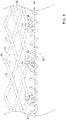
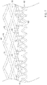
- FIG. 2 is “pulled down” or “peeled back” approximately 180 degrees about the joint 42 (described further below) in FIGS. 3 and 6 .
- FIGS. 4 , 5 , and 7 illustrate certain elements in phantom that are "behind” or otherwise “hidden” by the seal member 30 in the view and/or position shown in FIG. 2 .
- FIGS. 3-7 generally illustrate a partial side view looking radially inward toward a central longitudinal axis of the expandable anchor member 70 and/or the medical implant 16.
- the seal member 30 may include a plurality of layers of polymeric material.
- suitable polymeric materials may include, but are not necessarily limited to, polycarbonate, polyurethane, polyamide, polyether block amide, polyethylene, polyethylene terephthalate, polypropylene, polyvinylchloride, polytetrafluoroethylene, polysulfone, and copolymers, blends, mixtures or combinations thereof. Other configurations and/or other suitable materials are also contemplated.
- the modulus of elasticity may vary and/or be different from layer to layer. In other embodiments, the elongation to break may vary and/or be different from layer to layer.
- the seal member 30 may also include a reinforcement, a reinforcing layer, and/or one or more reinforcing members added to the polymeric material prior to curing.
- the reinforcement, the reinforcing layer, and/or the one or more reinforcing members may comprise a woven or nonwoven fabric and may be positioned within or between the various layers. In some embodiments, the reinforcement, the reinforcing layer, and/or the one or more reinforcing members may be positioned on a radially innermost surface or radially outermost surface of the seal member 30.
- the reinforcement, the reinforcing layer, and/or the one or more reinforcing members may be generally aligned. In some embodiments, the reinforcement, the reinforcing layer, and/or the one or more reinforcing members may be randomly oriented and/or disposed on the seal member 30.
- a distal end of the seal member 30 may include a reinforcing band 32 coupled to the seal member 30.
- the reinforcing band 32 may be integrally formed with, incorporated into, adhered to, and/or at least partially embedded within the seal member 30.
- the reinforcing band 32 may be formed from a woven or nonwoven fabric strip, a textile, or other thin flexible material. The reinforcing band 32 may provide tear resistance in the vicinity of sutures, filaments, or other attachment elements associated with components or aspects of the medical implant 16.
- each one of the plurality of valve leaflets 68 may be secured directly to the reinforcing band 32 and/or a distal end of the reinforcing band 32. In some embodiments, the plurality of valve leaflets 68 may not be secured directly to the distal end of the expandable anchor member 70.
- the reinforcing band 32 may include a plurality of perforations extending through the reinforcing band 32 and/or the seal member 30.
- the plurality of perforations may accommodate sutures passing therethrough (e.g., through the reinforcing band 32 and/or the seal member 30) to secure elements or aspects of the medical implant 16, such as (but not limited to) the plurality of valve leaflets 68 and/or the expandable anchor member 70, for example.
- One or more whip sutures 40 attach a distal end of the seal member 30 to a distal end of the plurality of valve leaflets 68 at a joint 42, preferably adjacent a distal end of the expandable anchor member 70, as seen in FIGS. 2-7 for example.
- the one or more whip sutures 40 may attach the reinforcing band 32 and/or a distal end of the reinforcing band 32 to the distal end of the plurality of valve leaflets 68 at a joint 42 adjacent a distal end of the expandable anchor member 70.
- the joint 42 may be disposed distally of a distal end of the expandable anchor member 70.
- the joint 42 may be disposed distally of a distalmost end of the expandable anchor member 70.
- the one or more whip sutures 40 may form one or more first helical spirals oriented in a first direction about the joint 42, as seen in FIGS. 3-7 for example.
- the one or more whip sutures 40 may include and/or form a plurality of windings about the joint 42.
- the one or more whip sutures 40 may be disposed distally of a distalmost filament, wire, filament intersection, and/or element (e.g., crown) of the expandable anchor member 70.
- the one or more whip sutures 40 may be disposed distally of a distal end of the expandable anchor member 70. In some embodiments, the one or more whip sutures 40 may be disposed distally of a distalmost end of the expandable anchor member 70. In some embodiments, a distal end of the expandable anchor member 70 may be disposed and/or positioned at one or more distal crowns 74, for example. In some embodiments, a distalmost end of the expandable anchor member 70 may be disposed and/or positioned at one or more distal crowns 74, for example.
- One or more distal lashing sutures 44 attach a distal portion of the seal member 30 to a distal end of the expandable anchor member 70. In some embodiments, one or more distal lashing sutures 44 may attach a distal portion of the seal member 30 to a distalmost end of the expandable anchor member 70. In some embodiments, the one or more distal lashing sutures 44 may attach the reinforcing band 32 to the distal end of the expandable anchor member 70. In some embodiments, the one or more distal lashing sutures 44 may attach the reinforcing band 32 to the distalmost end of the expandable anchor member 70.
- the one or more distal lashing sutures 44 may attach the one or more whip sutures 40 to the distal end and/or the one or more distal crowns 74 of the expandable anchor member 70, as seen in FIGS. 3-7 for example. In some embodiments, the one or more distal lashing sutures 44 may attach the one or more whip sutures 40 to the distalmost end and/or the one or more distal crowns 74 of the expandable anchor member 70.
- the one or more distal lashing sutures 44 directly attach the one or more whip sutures 40 to the distal end of the expandable anchor member 70. In some embodiments, the one or more distal lashing sutures 44 may directly attach the one or more whip sutures 40 to the distalmost end of the expandable anchor member 70. In some embodiments, the one or more distal lashing sutures 44 may be interwoven with the one or more whip sutures 40 and/or the plurality of windings of the one or more whip sutures 40 to form a suture lattice.
- the one or more distal lashing sutures 44 may be looped through an interior of one or more of the plurality of windings of the one or more whip sutures 40 to form the suture lattice.
- the one or more distal lashing sutures 44 may form one or more second helical spirals oriented in a second direction about the distal end of the expandable anchor member 70.
- the one or more distal lashing sutures 44 may form one or more second helical spirals oriented in a second direction about the distalmost end of the expandable anchor member 70.
- the first direction may be the same as the second direction. In some embodiments, the first direction may be opposite the second direction.
- the one or more distal lashing sutures 44 do not extend through the seal member 30 and/or the reinforcing band 32, as seen in FIGS. 3 and 4 for example.
- the one or more distal lashing sutures 44 may not pass through the plurality of perforations and/or through a thickness or a wall of the seal member 30 and/or the reinforcing band 32.
- the one or more distal lashing sutures 44 may attach a distal end of the seal member 30 to the expandable anchor member 70 distal of a distalmost filament intersection 72 and/or at the one or more distal crowns 74.
- the one or more distal lashing sutures 44 may attach a distal end of the seal member 30 to the expandable anchor member 70 at the distalmost filament intersection(s) 72 and distally of the distalmost filament intersection(s) 72. In some embodiments, the one or more distal lashing sutures 44 may be disposed between the seal member 30 and/or the reinforcing band 32 and the plurality of valve leaflets 68.
- each of the one or more distal lashing sutures 44 may extend radially outward through the plurality of perforations and/or through a thickness or a wall of the seal member 30 and/or the reinforcing band 32, for example at a first hole or aperture 50, under one or more of the plurality of windings of the one or more whip sutures 40, and radially back inward through a second hole or aperture 50, thereby forming an interlocking and/or interwoven arrangement between the one or more distal lashing sutures 44 and the one or more whip sutures 40, as seen in FIG. 5 for example.
- the one or more distal lashing sutures 44 may be secured in place and/or back to itself with a knot or other fastening element.
- ends of the one or more distal lashing sutures 44 forming the knot or other fastening element may be melted, adhesively bonded, or otherwise fused to each other to form a permanent attachment therebetween.
- the knot or other fastening element may be disposed radially outward of the seal member 30 and/or the reinforcing band 32, as seen in FIG. 5 for example.
- the knot or other fastening element may be disposed between the plurality of valve leaflets 68 and the seal member 30 and/or the reinforcing band 32, and/or may be disposed radially inward of the seal member and/or the reinforcing band 32, as seen in FIGS. 4 and 7 for example.
- the one or more distal lashing sutures 44 may be interwoven with the one or more whip sutures 40 to form a suture lattice, as seen in FIGS. 6-7 for example.
- the one or more distal lashing sutures 44 may include and/or form a plurality of windings about the expandable anchor member 70 and/or individual elements thereof - a distal end, a distalmost filament, and/or a distal crown 74, for example.
- the one or more distal lashing sutures 44 may include and/or form a plurality of windings about the distalmost filament intersection(s) 72.
- the plurality of windings of the one or more distal lashing sutures 44 may be interwoven with the one or more whip sutures 40 at every other winding of the one or more distal lashing sutures 44 along at least a portion of the one or more distal lashing sutures 44 and/or the one or more whip sutures 40. In some embodiments, the plurality of windings of the one or more whip sutures 40 may be interwoven with the one or more distal lashing sutures 44 at adjacent and/or every winding of the one or more whip sutures 40 along at least a portion of the one or more distal lashing sutures 44 and/or the one or more whip sutures 40.
- some of the plurality of windings of the one or more distal lashing sutures 44 may be interwoven with several adjacent windings of the one or more whip sutures 40. In some embodiments, groups of adjacent interwoven windings may be spaced apart by one or more of the plurality of windings of the one or more whip sutures 40 and/or one or more of the plurality of windings of the one or more distal lashing sutures 44.
- a plurality of proximal lashing sutures 46 attach a proximal portion of the seal member 30 to the distal portion of the expandable anchor member 70, as seen in FIG. 2 for example.
- a grommet 38 may be disposed along an outer surface of the seal member 30 and/or at least partially embedded within the seal member 30 at each of the plurality of proximal lashing sutures 46 to aid in attaching the seal member 30 to the expandable anchor member 70.
- the plurality of proximal lashing sutures 46 may extend through the grommet(s) 38.
- the plurality of proximal lashing sutures 46 may attach the proximal portion of the seal member 30 to the distal portion of the expandable anchor member 70 proximal of the distalmost filament intersection 72 and/or the one or more distal crowns 74. In some embodiments, the plurality of proximal lashing sutures 46 may attach the proximal portion of the seal member 30 to the expandable anchor member 70 at non-consecutive filament intersections 72, as may be seen in FIG. 2 for example. In some embodiments, the plurality of proximal lashing sutures 46 may attach the proximal portion of the seal member 30 to the expandable anchor member 70 only at non-consecutive filament intersections 72 of the expandable anchor member 70.
- a method of manufacturing a medical implant 16 and/or a replacement heart valve implant includes positioning a tissue subassembly including a plurality of valve leaflets 68 and a seal member 30 relative to an expandable anchor member 70 such that the plurality of valve leaflets 68 is disposed within a lumen of the expandable anchor member 70 and the seal member 30 is disposed at least partially along an outer surface of the expandable anchor member 70, the expandable anchor member 70 forming a plurality of filament intersections 72 distributed around a circumference of the expandable anchor member 70.
- One or more whip sutures 40 attach a distal end of the seal member 30 to a distal end of the plurality of valve leaflets 68 at a joint 42.
- the tissue subassembly may be assembled and/or formed prior to positioning the tissue subassembly relative to the expandable anchor member 70.
- the method of manufacturing a medical implant 16 and/or a replacement heart valve implant includes attaching the tissue subassembly to the expandable anchor member 70 after positioning the tissue subassembly relative to the expandable anchor member 70.
- One or more distal lashing sutures 44 attach the seal member 30 to the expandable anchor member 70 distal of a distalmost filament intersection 72.
- the one or more distal lashing sutures 44 may attach the one or more whip sutures 40 to a distal end (e.g., to a distal crown 74) of the expandable anchor member 70.
- the one or more distal lashing sutures 44 directly attach the one or more whip sutures 40 to a distal end (e.g., to a distal crown 74, to each distal crown 74, etc.) of the expandable anchor member 70.
- the one or more whip sutures 40 may be interwoven with the one or more distal lashing sutures 44 to form a suture lattice.
- a method of manufacturing a medical implant 16 and/or a replacement heart valve implant may include forming a first helical spiral in a first direction about the joint 42 with the one or more whip sutures 40. In some embodiments, a method of manufacturing a medical implant 16 and/or a replacement heart valve implant may include forming a second helical spiral in a second direction about the joint 42 with the one or more distal lashing sutures 44. In some embodiments, the first direction may be the same as the second direction. In some embodiments, the first direction may be opposite the second direction.
- the method of manufacturing a medical implant 16 and/or a replacement heart valve implant includes attaching a proximal portion of the seal member 30 to a distal portion of the expandable anchor member 70 proximal of the distalmost filament intersection 72.
- the plurality of proximal lashing sutures 46 attach the proximal portion of the seal member 30 to the distal portion of the expandable anchor member 70 at non-consecutive filament intersections 72 of the expandable anchor member 70.
- the plurality of proximal lashing sutures 46 may attach the proximal portion of the seal member 30 to the distal portion of the expandable anchor member 70 only at non-consecutive filament intersections 72 of the expandable anchor member 70.
- the materials that can be used for the various components of the medical device system 10 (and/or other systems disclosed herein) and the various elements thereof disclosed herein may include those commonly associated with medical devices.
- the following discussion makes reference to the delivery system and/or the medical implant 16.
- this is not intended to limit the devices and methods described herein, as the discussion may be applied to other elements, members, components, or devices disclosed herein, such as, but not limited to, the expandable anchor member 70 and/or elements or components thereof.
- the medical device system 10, the delivery system, and/or the medical implant 16, and/or components thereof may be made from a metal, metal alloy, polymer (some examples of which are disclosed below), a metal-polymer composite, ceramics, combinations thereof, and the like, or other suitable material.
- suitable polymers may include polytetrafluoroethylene (PTFE), ethylene tetrafluoroethylene (ETFE), fluorinated ethylene propylene (FEP), polyoxymethylene (POM, for example, DELRIN ® available from DuPont), polyether block ester, polyurethane (for example, Polyurethane 85A), polypropylene (PP), polyvinylchloride (PVC), polyether-ester (for example, ARNITEL ® available from DSM Engineering Plastics), ether or ester based copolymers (for example, butylene/poly(alkylene ether) phthalate and/or other polyester elastomers such as HYTREL ® available from DuPont), polyamide (for example, DURETHAN ® available from Bayer or CRISTAMID ® available from Elf Atochem), elastomeric polyamides, block polyamide/ethers, polyether block amide (PEBA, for example available under the trade name PEBAX ®
- suitable metals and metal alloys include stainless steel, such as 304V, 304L, and 316LV stainless steel; mild steel; nickel-titanium alloy such as linear-elastic and/or super-elastic nitinol; other nickel alloys such as nickel-chromium-molybdenum alloys (e.g., UNS: N06625 such as INCONEL ® 625, UNS: N06022 such as HASTELLOY ® C-22 ® , UNS: N10276 such as HASTELLOY ® C276 ® , other HASTELLOY ® alloys, and the like), nickel-copper alloys (e.g., UNS: N04400 such as MONEL ® 400, NICKEL VAC ® 400, NICORROS ® 400, and the like), nickel-cobalt-chromium-molybdenum alloys (e.g., UNS: R30035 such as MP35-N ® and the like), nickel-co
- Linear elastic and/or non-super-elastic nitinol may be distinguished from super elastic nitinol in that the linear elastic and/or non-super-elastic nitinol does not display a substantial "superelastic plateau” or “flag region” in its stress/strain curve like super elastic nitinol does.
- linear elastic and/or non-super-elastic nitinol as recoverable strain increases, the stress continues to increase in a substantially linear, or a somewhat, but not necessarily entirely linear relationship until plastic deformation begins or at least in a relationship that is more linear than the super elastic plateau and/or flag region that may be seen with super elastic nitinol.
- linear elastic and/or non-super-elastic nitinol may also be termed "substantially" linear elastic and/or non-super-elastic nitinol.
- linear elastic and/or non-super-elastic nitinol may also be distinguishable from super elastic nitinol in that linear elastic and/or non-super-elastic nitinol may accept up to about 2-5% strain while remaining substantially elastic (e.g., before plastically deforming) whereas super elastic nitinol may accept up to about 8% strain before plastically deforming. Both of these materials can be distinguished from other linear elastic materials such as stainless steel (that can also be distinguished based on its composition), which may accept only about 0.2 to 0.44 percent strain before plastically deforming.
- the linear elastic and/or non-super-elastic nickel-titanium alloy is an alloy that does not show any martensite/austenite phase changes that are detectable by differential scanning calorimetry (DSC) and dynamic metal thermal analysis (DMTA) analysis over a large temperature range.
- DSC differential scanning calorimetry
- DMTA dynamic metal thermal analysis
- the mechanical bending properties of such material may therefore be generally inert to the effect of temperature over this very broad range of temperature.
- the mechanical bending properties of the linear elastic and/or non-super-elastic nickel-titanium alloy at ambient or room temperature are substantially the same as the mechanical properties at body temperature, for example, in that they do not display a super-elastic plateau and/or flag region.
- the linear elastic and/or non-super-elastic nickel-titanium alloy maintains its linear elastic and/or non-super-elastic characteristics and/or properties.
- the linear elastic and/or non-super-elastic nickel-titanium alloy may be in the range of about 50 to about 60 weight percent nickel, with the remainder being essentially titanium. In some embodiments, the composition is in the range of about 54 to about 57 weight percent nickel.
- a suitable nickel-titanium alloy is FHP-NT alloy commercially available from Furukawa Techno Material Co. of Kanagawa, Japan. Other suitable materials may include ULTANIUM TM (available from Neo-Metrics) and GUM METAL TM (available from Toyota).
- a superelastic alloy for example a superelastic nitinol can be used to achieve desired properties.
- portions or all of the delivery system and/or the medical implant 16, and/or components thereof may also be doped with, made of, or otherwise include a radiopaque material.
- Radiopaque materials are understood to be materials capable of producing a relatively bright image on a fluoroscopy screen or another imaging technique during a medical procedure. This relatively bright image aids the user of the medical device system 10 in determining its location.
- Some examples of radiopaque materials can include, but are not limited to, gold, platinum, palladium, tantalum, tungsten alloy, polymer material loaded with a radiopaque filler, and the like. Additionally, other radiopaque marker bands and/or coils may also be incorporated into the design of the medical device system 10 to achieve the same result.
- a degree of Magnetic Resonance Imaging (MRI) compatibility is imparted into the medical device system 10.
- the delivery system and/or the medical implant 16, and/or components or portions thereof may be made of a material that does not substantially distort the image and create substantial artifacts (i.e., gaps in the image). Certain ferromagnetic materials, for example, may not be suitable because they may create artifacts in an MRI image.
- the delivery system and/or the medical implant 16, or portions thereof may also be made from a material that the MRI machine can image.
- Some materials that exhibit these characteristics include, for example, tungsten, cobalt-chromium-molybdenum alloys (e.g., UNS: R30003 such as ELGILOY ® , PHYNOX ® , and the like), nickel-cobalt-chromium-molybdenum alloys (e.g., UNS: R30035 such as MP35-N ® and the like), nitinol, and the like, and others.
- cobalt-chromium-molybdenum alloys e.g., UNS: R30003 such as ELGILOY ® , PHYNOX ® , and the like
- nickel-cobalt-chromium-molybdenum alloys e.g., UNS: R30035 such as MP35-N ® and the like
- nitinol and the like, and others.
- an exterior surface of the medical device system 10 may be sandblasted, beadblasted, sodium bicarbonate-blasted, electropolished, etc.
- a coating for example a lubricious, a hydrophilic, a protective, or other type of coating may be applied over portions or all of the outer sheath, or in embodiments without an outer sheath over portions of the delivery system, or other portions of the medical device system 10.
- Hydrophobic coatings such as fluoropolymers provide a dry lubricity which improves device handling and device exchanges. Lubricious coatings improve steerability and improve lesion crossing capability.
- Suitable lubricious polymers are well known in the art and may include silicone and the like, hydrophilic polymers such as high-density polyethylene (HDPE), polytetrafluoroethylene (PTFE), polyarylene oxides, polyvinylpyrolidones, polyvinylalcohols, hydroxy alkyl cellulosics, algins, saccharides, caprolactones, and the like, and mixtures and combinations thereof. Hydrophilic polymers may be blended among themselves or with formulated amounts of water insoluble compounds (including some polymers) to yield coatings with suitable lubricity, bonding, and solubility.
- hydrophilic polymers such as high-density polyethylene (HDPE), polytetrafluoroethylene (PTFE), polyarylene oxides, polyvinylpyrolidones, polyvinylalcohols, hydroxy alkyl cellulosics, algins, saccharides, caprolactones, and the like, and mixtures and combinations thereof.
- the coating and/or sheath may be formed, for example, by coating, extrusion, co-extrusion, interrupted layer co-extrusion (ILC), or fusing several segments end-to-end.
- the layer may have a uniform stiffness or a gradual reduction in stiffness from the proximal end to the distal end thereof. The gradual reduction in stiffness may be continuous as by ILC or may be stepped as by fusing together separate extruded tubular segments.
- the outer layer may be impregnated with a radiopaque filler material to facilitate radiographic visualization. Those skilled in the art will recognize that these materials can vary widely without deviating from the scope of the present invention.
Description
- The present disclosure pertains to medical devices, and methods for manufacturing and/or using medical devices. More particularly, the present disclosure pertains to an improved stitching and/or lashing pattern for a medical device and/or a replacement heart valve.
- A wide variety of intracorporeal medical devices have been developed for medical use, for example, intravascular use. Some of these devices include guidewires, catheters, medical device delivery systems (e.g., for stents, grafts, replacement valves, etc.), and the like. These devices are manufactured by any one of a variety of different manufacturing methods and may be used according to any one of a variety of methods. Of the known medical devices and methods, each has certain advantages and disadvantages. There is an ongoing need to provide alternative medical devices as well as alternative methods for manufacturing and using medical devices.
-
EP 2 898 858 A1 discloses a prosthetic heart valve with a cuff and a plurality of valve leaflets. - The present invention pertains to a replacement heart valve as defined in the appended claims. The replacement heart valve implant in accordance with the invention comprises an expandable anchor member, a plurality of valve leaflets disposed within the anchor member, a seal member disposed about a distal portion of the anchor member, one or more whip sutures attaching a distal end of the seal member to a distal end of the plurality of valve leaflets at a joint, one or more distal lashing sutures attaching a distal portion of the seal member to a distal end of the anchor member, and a plurality of proximal lashing sutures attaching a proximal portion of the seal member to the distal portion of the anchor member, wherein the one or more distal lashing sutures does not extend through the seal member. The one or more distal lashing sutures directly attach the one or more whip sutures to the distal end of the anchor member.
- In addition, or alternatively, and in a second aspect, the distal end of the seal member includes a reinforcing band coupled to the seal member.
- In addition, or alternatively, and in a third aspect, the reinforcing band is at least partially embedded within the seal member.
- In addition, or alternatively, and in a fourth aspect, the one or more whip sutures attach the reinforcing band to the distal end of the plurality of valve leaflets.
- In addition, or alternatively, and in a fifth aspect, the one or more distal lashing sutures attach the reinforcing band to the distal end of the anchor member.
- In addition, or alternatively, and in an eighth aspect, the one or more whip sutures form one or more first helical spirals about the joint.
- In addition, or alternatively, and in a ninth aspect, the one or more distal lashing sutures form one or more second helical spirals about the distal end of the anchor member.
- The present invention is also directed to a suture lattice for the above defined replacement heart valve implant. The suture lattice comprises a whip suture attaching a plurality of valve leaflets to a seal member at a joint, and a distal lashing suture attaching a distal portion of the seal member to a distal end of an expandable anchor member, wherein the distal lashing suture is interwoven with the whip suture.
- In addition, or alternatively, and in an eleventh aspect, the plurality of valve leaflets is not directly attached to the anchor member.
- In addition, or alternatively, and in a twelfth aspect, the whip suture forms a first spiral oriented in a first direction about the joint.
- In addition, or alternatively, and in a thirteenth aspect, the distal lashing suture forms a second spiral oriented in a second direction about the distal end of the anchor member.
- In addition, or alternatively, and in a fourteenth aspect, the first direction is the same as the second direction.
- In addition, or alternatively, and in a fifteenth aspect, the first direction is opposite the second direction.
- The present invention is also directed to a method of manufacturing the above defined replacement heart valve implant. The method comprises positioning a tissue subassembly including a plurality of valve leaflets and a seal member relative to an expandable anchor member such that the plurality of valve leaflets is disposed within a lumen of the expandable anchor member and the seal member is disposed at least partially along an outer surface of the anchor member, the expandable anchor member forming a plurality of filament intersections distributed around a circumference of the expandable anchor member, attaching the tissue subassembly to the expandable anchor member, wherein one or more whip sutures attach a distal end of the seal member to a distal end of the plurality of valve leaflets at a joint, and one or more distal lashing sutures attach the seal member to the expandable anchor member distal of a distalmost filament intersection, and attaching a proximal portion of the seal member to a distal portion of the expandable anchor member proximal of the distalmost filament intersection, wherein a plurality of proximal lashing sutures attach the seal member at non-consecutive filament intersections of the expandable anchor member.
- In addition, or alternatively, and in a seventeenth aspect, the one or more distal lashing sutures and the one or more whip sutures form a suture lattice.
- In addition, or alternatively, and in an eighteenth aspect, the one or more distal lashing sutures attach the one or more whip sutures to a distal end of the expandable anchor member.
- In addition, or alternatively, and in a nineteenth aspect, the one or more distal lashing sutures is interwoven with the one or more whip sutures.
- In addition, or alternatively, and in a twentieth aspect, the joint is disposed distally of a distal end of the expandable anchor member.
- The above summary of some embodiments, aspects, and/or examples is not intended to describe each disclosed embodiment or every implementation of the present disclosure. The Figures, and Detailed Description, which follow, more particularly exemplify these embodiments.
- The disclosure may be more completely understood in consideration of the following detailed description in connection with the accompanying drawings, in which:
-
FIG. 1 illustrates an example medical device system; -
FIG. 2 illustrates an example medical implant associated with an example medical device system; -
FIG. 3 illustrates a portion of an example medical implant associated with an example medical device system; -
FIG. 4 illustrates a portion of an example medical implant associated with an example medical device system; -
FIG. 5 illustrates a portion of an example medical implant associated with an example medical device system; -
FIG. 6 illustrates a portion of an example medical implant associated with an example medical device system; and -
FIG. 7 illustrates a portion of an example medical implant associated with an example medical device system. - While aspects of the disclosure are amenable to various modifications and alternative forms, specifics thereof have been shown by way of example in the drawings and will be described in detail. It should be understood, however, that the intention is not to limit aspects of the disclosure to the particular embodiments described. On the contrary, the intention is to cover all modifications, equivalents, and alternatives.
- The following description should be read with reference to the drawings, which are not necessarily to scale, wherein like reference numerals indicate like elements throughout the several views. The detailed description and drawings are intended to illustrate but not limit the claimed invention. Those skilled in the art will recognize that the various elements described and/or shown may be arranged in various combinations and configurations without departing from the scope of the disclosure. The detailed description and drawings illustrate example embodiments of the claimed invention.
- Generally speaking, in terms of the orientation of the structural elements relative to each other and the operation of the disclosed device(s), a proximal end may be considered closest to the user (or external to a patient) and a distal end farthest from the user (or internal to a patient). However, the skilled artisan will appreciate that the orientations and/or directions may be reversed as necessary or appropriate.
- For the following defined terms, these definitions shall be applied, unless a different definition is given in the claims or elsewhere in this specification.
- All numeric values are herein assumed to be modified by the term "about," whether or not explicitly indicated. The term "about", in the context of numeric values, generally refers to a range of numbers that one of skill in the art would consider equivalent to the recited value (i.e., having the same function or result). In many instances, the term "about" may include numbers that are rounded to the nearest significant figure. Other uses of the term "about" (i.e., in a context other than numeric values) may be assumed to have their ordinary and customary definition(s), as understood from and consistent with the context of the specification, unless otherwise specified.
- The recitation of numerical ranges by endpoints includes all numbers within that range, including the endpoints (e.g. 1 to 5 includes 1, 1.5, 2, 2.75, 3, 3.80, 4, and 5).
- Although some suitable dimensions, ranges and/or values pertaining to various components, features and/or specifications are disclosed, one of skill in the art, incited by the present disclosure, would understand desired dimensions, ranges and/or values may deviate from those expressly disclosed.
- As used in this specification and the appended claims, the singular forms "a", "an", and "the" include plural referents unless the content clearly dictates otherwise. As used in this specification and the appended claims, the term "or" is generally employed in its sense including "and/or" unless the content clearly dictates otherwise.
- Relative terms such as "proximal", "distal", "advance", "retract", variants thereof, and the like, may be generally be considered with respect to the positioning, direction, and/or operation of various elements relative to a user/operator/manipulator of the device, wherein "proximal" and "retract" indicate or refer to closer to or toward the user and "distal" and "advance" indicate or refer to farther from or away from the user. Other relative terms, such as "upstream", "downstream", "inflow", and "outflow" refer to a direction of fluid flow within a lumen, such as a body lumen, a blood vessel, or within a device.
- It is noted that references in the specification to "an embodiment", "some embodiments", "other embodiments", etc., indicate that the embodiment(s) described may include a particular feature, structure, or characteristic, but every embodiment may not necessarily include the particular feature, structure, or characteristic. Moreover, such phrases are not necessarily referring to the same embodiment. Further, when a particular feature, structure, or characteristic is described in connection with an embodiment, it would be within the knowledge of one skilled in the art to effect such feature, structure, or characteristic in connection with other embodiments, whether or not explicitly described, unless clearly stated to the contrary. That is, the various individual elements described below, even if not explicitly shown in a particular combination, are nevertheless contemplated as being combinable or arrangable with each other to form other additional embodiments or to complement and/or enrich the described embodiment(s), as would be understood by one of ordinary skill in the art.
- For the purpose of clarity, certain identifying numerical nomenclature (e.g., first, second, third, fourth, etc.) may be used throughout the description and/or claims to name and/or differentiate between various described and/or claimed features. It is to be understood that the numerical nomenclature is not intended to be limiting and is exemplary only. In some embodiments, alterations of and deviations from previously-used numerical nomenclature may be made in the interest of brevity and clarity. That is, a feature identified as a "first" element may later be referred to as a "second" element, a "third" element, etc. or may be omitted entirely, and/or a different feature may be referred to as the "first" element. The meaning and/or designation in each instance will be apparent to the skilled practitioner.
- Diseases and/or medical conditions that impact the cardiovascular system are prevalent in the United States and throughout the world. Traditionally, treatment of the cardiovascular system was often conducted by directly accessing the impacted part of the system. For example, treatment of a blockage in one or more of the coronary arteries was traditionally treated using coronary artery bypass surgery. As can be readily appreciated, such therapies are rather invasive to the patient and require significant recovery times and/or treatments. More recently, less invasive therapies have been developed, for example, where a blocked coronary artery could be accessed and treated via a percutaneous catheter (e.g., angioplasty). Such therapies have gained wide acceptance among patients and clinicians.
- Some relatively common medical conditions may include or be the result of inefficiency, ineffectiveness, or complete failure of one or more of the valves within the heart. For example, failure of the aortic valve can have a serious effect on a human and could lead to serious health condition and/or death if not dealt with. Treatment of defective heart valves poses other challenges in that the treatment often requires the repair or outright replacement of the defective valve. Such therapies may be highly invasive to the patient. Disclosed herein are medical devices that may be used within a portion of the cardiovascular system in order to diagnose, treat, and/or repair the system. At least some of the medical devices disclosed herein may include a replacement heart valve (e.g., a replacement aortic valve). In addition, the devices disclosed herein may deliver the replacement heart valve percutaneously and, thus, may be much less invasive to the patient. The devices disclosed herein may also provide a number of additional desirable features and benefits as described in more detail below.
- The figures illustrate selected components and/or arrangements of a
medical device system 10. It should be noted that in any given figure, some features of themedical device system 10 may not be shown, or may be shown schematically, for simplicity. Additional details regarding some of the components of themedical device system 10 may be illustrated in other figures in greater detail. Amedical device system 10 may be used to deliver and/or deploy a variety of medical devices to a number of locations within the anatomy. In at least some embodiments, themedical device system 10 may include a replacement heart valve delivery system (e.g., a replacement aortic valve delivery system) that can be used for percutaneous delivery of a replacement heart valve. This, however, is not intended to be limiting as themedical device system 10 may also be used for other interventions including mitral valve replacement, valve repair, valvuloplasty, and the like, or other similar interventions. - The
medical device system 10, as seen inFIG. 1 for example, may generally be described as a catheter system that includes a delivery system having anouter sheath 12 for a medical implant 16 (i.e., a replacement heart valve implant, for example, which term may be used interchangeably with the term "medical implant" herein) which may be coupled to the delivery system and disposed within a lumen of theouter sheath 12 during delivery of themedical implant 16. In some embodiments, the delivery system may include aninner catheter 14 extending at least partially through the outer sheath 12 (partially seen in phantom inFIG. 1 ). In some embodiments, themedical implant 16 may be coupled to theinner catheter 14 and disposed within the lumen of theouter sheath 12 during delivery of themedical implant 16. In some embodiments, ahandle 18 may be disposed and/or attached at a proximal end of the delivery system, as seen inFIG. 1 , and may include one or more actuation means associated therewith. In some embodiments, thehandle 18 may be configured to manipulate the position of theouter sheath 12 relative to theinner catheter 14, and/or aid in the deployment of themedical implant 16. In some embodiments, themedical device system 10 may include a nose cone disposed at a distal end of a guidewire extension tube, wherein the guidewire extension tube may extend distally from theinner catheter 14. In at least some embodiments, the nose cone may be designed to have an atraumatic shape. In some embodiments, the nose cone may include a ridge or ledge that is configured to abut a distal tip of theouter sheath 12 during delivery of themedical implant 16. - In use, the
medical device system 10 may be advanced percutaneously through the vasculature to a position adjacent to an area of interest or a target location. For example, themedical device system 10 may be advanced through the vasculature and across the aortic arch to a position adjacent to a defective aortic valve. Alternative approaches to treat a defective aortic valve and/or other heart valve(s) are also contemplated with themedical device system 10. During delivery, themedical implant 16 may be generally disposed in an elongated and low profile "delivery" configuration within the delivery system and/or theouter sheath 12 coupled to and/or distal of theinner catheter 14. Once positioned, theouter sheath 12 may be retracted relative to theinner catheter 14, which may be held stationary by thehandle 18, and/or themedical implant 16 to expose themedical implant 16. Themedical implant 16 may be actuated using thehandle 18 in order to translate themedical implant 16 into a generally expanded and larger profile "deployed" configuration suitable for implantation within the anatomy (as seen inFIG. 2 , for example). When themedical implant 16 is suitably deployed within the anatomy, themedical implant 16 may be released and/or detached from themedical device system 10, the delivery system can be removed from the vasculature, leaving themedical implant 16 in place in a "released" configuration to function as, for example, a suitable replacement for the native aortic valve. In at least some interventions, themedical implant 16 may be deployed within the native valve (e.g., the native valve is left in place and not excised). Alternatively, the native valve may be removed (such as through valvuloplasty, for example) and themedical implant 16 may be deployed in its place as a replacement. - In some embodiments, the
inner catheter 14 may include one or more lumens extending therethrough. For example, in some embodiments, theinner catheter 14 may include a first lumen, a second lumen, a third lumen, and a fourth lumen. Other configurations are also contemplated. In general, the one or more lumens extend along an entire length of theinner catheter 14. Other embodiments are contemplated, however, where one or more of the one or more lumens extend along only a portion of the length of theinner catheter 14. In some embodiments, a distal region of theinner catheter 14 may include a step in outer diameter that defines a decreased diameter section. In some embodiments, the decreased diameter section may define a region where other components of themedical device system 10 may be attached. For example, in some embodiments, a coupler assembly may be attached to theinner catheter 14 at the decreased diameter section and/or at a distal end of theinner catheter 14. In some embodiments, the coupler assembly may releasably couple themedical implant 16 to theinner catheter 14. - In some embodiments, disposed within one of the lumens of the
inner catheter 14 may be at least one actuator element, which may be used to actuate (i.e., translate axially or longitudinally, and/or expand) themedical implant 16 between a delivery configuration and a deployed configuration. In some embodiments, themedical device system 10 may include at least one actuator element. In some embodiments, the at least one actuator element may include a plurality of actuator elements, two actuator elements, three actuator elements, four actuator elements, or another suitable or desired number of actuator elements. For the purpose of illustration only, themedical device system 10 and/or themedical implant 16 ofFIG. 2 is configured to use three actuator elements (not shown). In use, a proximal end of an actuator element may be connected to thehandle 18, and/or manipulated or otherwise actuated by a user using thehandle 18, to shift theexpandable anchor member 70 and/or themedical implant 16 from a "delivery" configuration to a "deployed" configuration, and later to a "released" configuration. During the release process for themedical implant 16, (e.g., as themedical implant 16 is actuated from the "delivery" configuration to the "deployed" configuration to the "released" configuration), the at least one actuator element may be retracted, withdrawn, and/or translated proximally relative to theinner catheter 14, themedical implant 16, and/or theexpandable anchor member 70. Some suitable but non-limiting materials for the actuator element, for example metallic materials or polymeric materials, may be described below. - It is to be noted that in order to facilitate understanding, certain features of the disclosure may be described in the singular, even though those features may be plural or recurring within the disclosed embodiment(s). Each instance of the features may include and/or be encompassed by the singular disclosure(s), unless expressly stated to the contrary. For example, a reference to "the actuator element", "the locking element", "the lumen", or other features may be equally referred to all instances and quantities beyond one of said feature. As such, it will be understood that the following discussion may apply equally to any and/or all of the components for which there are more than one within the medical implant 16 (i.e., the at least one actuator element, the plurality of locking elements, etc.) and/or the
medical device system 10, unless explicitly stated to the contrary. Additionally, not all instances of some elements or features may be shown in each figure for clarity. -
FIG. 2 illustrates some selected components of themedical implant 16. For example, here it can be seen that themedical implant 16 may include a plurality of valve leaflets 68 (e.g., bovine pericardial, polymeric, etc.) which may be secured to anexpandable anchor member 70 that is reversibly actuatable between an elongated "delivery" configuration, and an expanded "deployed" configuration. In some embodiments, theexpandable anchor member 70 may form a tubular structure defining a central longitudinal axis and a lumen extending through theexpandable anchor member 70 along, parallel to, coaxial with, and/or coincident with the central longitudinal axis. In some embodiments, theexpandable anchor member 70 may be and/or include a braid formed from one or more filaments or wires (e.g., a single filament or wire, two filaments or wires, etc.). Other configurations are also contemplated. Some suitable but non-limiting materials for theexpandable anchor member 70, for example metallic materials or polymeric materials, may be described below. In some embodiments, theexpandable anchor member 70 may form a plurality offilament intersections 72 distributed around a circumference of theexpandable anchor member 70. - In some embodiments, the
medical implant 16 may include a plurality of lockingelements 76 attached to theexpandable anchor member 70, the plurality of lockingelements 76 being configured to lock theexpandable anchor member 70 in the "deployed" and/or "released" configuration(s). In some embodiments, at least one actuator element may be configured to actuate theexpandable anchor member 70 and/or themedical implant 16 between the "delivery" configuration and the "deployed" configuration and/or the "released" configuration. - In some embodiments, the plurality of locking
elements 76 may each comprise an axially movable post member, for example at the commissure portions of the valve leaflets 68 (the post member may sometimes be referred to as a portion of a commissure post, which may serve to secure thevalve leaflets 68, or the post member may be connected and/or attached to a commissure post), and a buckle member or other receiving element configured to slidably receive the post member therein to engage with the buckle member and thereafter lock theexpandable anchor member 70 and/or themedical implant 16 in the "deployed" and/or the "released" configuration(s). In other words, in at least some embodiments, amedical implant 16 may include a plurality of post members and a corresponding plurality of buckle members. Other configurations and correspondences are also contemplated. Some suitable but non-limiting materials for the buckle member and/or the post member, for example metallic materials or polymeric materials, may be described below. - In some embodiments, the plurality of
valve leaflets 68 may be secured to theexpandable anchor member 70 at, adjacent to, and/or using (at least in part) individual, corresponding post members. In some embodiments, the plurality ofvalve leaflets 68 may also be secured to a distal end of theexpandable anchor member 70. In at least some embodiments, a distal end of theexpandable anchor member 70 may be interchangeably described as an "inflow" end or an "upstream" end of theexpandable anchor member 70 and/or themedical implant 16. In some embodiments, the plurality ofvalve leaflets 68 may be coupled and/or secured (i.e., to the post member, to theexpandable anchor member 70, and/or back to themselves) using one or more sutures, threads, wires, filaments, or other suitable elements. In some embodiments, the plurality ofvalve leaflets 68 may be coupled and/or secured (i.e., to the post member, to theexpandable anchor member 70, and/or back to themselves) using an adhesive, a bonding agent, or other suitable securing means. In some embodiments, the plurality ofvalve leaflets 68 may be coupled and/or secured (i.e., to the post member, to theexpandable anchor member 70, and/or back to themselves) using a fabric strip, a textile, or other thin flexible material. In some embodiments, the plurality ofvalve leaflets 68 may not be directly attached to theexpandable anchor member 70. - In some embodiments, the post members and/or the commissure posts may be secured and/or attached to the expandable anchor member 70 (e.g., along the interior of the expandable anchor member) with sutures, tethers, adhesives, or other suitable elements. In some embodiments, the commissure post and/or the post member may include one or more holes or other features provided to aid in securing and/or attaching the commissure post and/or the post member to the
expandable anchor member 70. Positioned adjacent to (e.g., aligned with) the plurality of post members are a corresponding plurality of buckle members, which may be secured and/or fixedly attached to the expandable anchor member 70 (e.g., along the interior of the expandable anchor member 70) with sutures, adhesives, or other suitable mechanisms. In some embodiments, the post member may be axially translatable relative to the buckle member generally parallel to the central longitudinal axis of theexpandable anchor member 70 when the post member is at least partially disposed within and/or engaged with the buckle member. - In some embodiments, one buckle member may be fixedly attached to the
expandable anchor member 70 adjacent to each of the three post members. Accordingly, in some embodiments, theexpandable anchor member 70 may have a total of three buckle members and three post members attached thereto. Similarly, one actuator element may be associated with each post member and buckle member, for a total of three actuator elements in the illustrated example(s). Other embodiments are contemplated where fewer or more buckle members, post members, and/or actuator elements may be utilized. - In some embodiments, a
seal member 30 may be circumferentially disposed on and/or about a distal portion of theexpandable anchor member 70, as seen inFIG. 2 for example, and as the term suggests, may help to seal an exterior of themedical implant 16 within and/or against a target site or area of interest upon deployment, thereby preventing leakage around themedical implant 16. In some embodiments, theseal member 30 may be disposed about theexpandable anchor member 70. In some embodiments, theseal member 30 may be disposed around a perimeter and/or on or against an exterior surface of theexpandable anchor member 70. In some embodiments, theseal member 30 may be coupled and/or secured to theexpandable anchor member 70. - For the purpose of illustration and ease of understanding, the
seal member 30 shown inFIG. 2 is "pulled down" or "peeled back" approximately 180 degrees about the joint 42 (described further below) inFIGS. 3 and6 .FIGS. 4 ,5 , and7 illustrate certain elements in phantom that are "behind" or otherwise "hidden" by theseal member 30 in the view and/or position shown inFIG. 2 .FIGS. 3-7 generally illustrate a partial side view looking radially inward toward a central longitudinal axis of theexpandable anchor member 70 and/or themedical implant 16. - In some embodiments, the
seal member 30 may include a plurality of layers of polymeric material. Some suitable polymeric materials may include, but are not necessarily limited to, polycarbonate, polyurethane, polyamide, polyether block amide, polyethylene, polyethylene terephthalate, polypropylene, polyvinylchloride, polytetrafluoroethylene, polysulfone, and copolymers, blends, mixtures or combinations thereof. Other configurations and/or other suitable materials are also contemplated. - In some embodiments, the modulus of elasticity may vary and/or be different from layer to layer. In other embodiments, the elongation to break may vary and/or be different from layer to layer. In some embodiments, the
seal member 30 may also include a reinforcement, a reinforcing layer, and/or one or more reinforcing members added to the polymeric material prior to curing. The reinforcement, the reinforcing layer, and/or the one or more reinforcing members may comprise a woven or nonwoven fabric and may be positioned within or between the various layers. In some embodiments, the reinforcement, the reinforcing layer, and/or the one or more reinforcing members may be positioned on a radially innermost surface or radially outermost surface of theseal member 30. In some embodiments, the reinforcement, the reinforcing layer, and/or the one or more reinforcing members may be generally aligned. In some embodiments, the reinforcement, the reinforcing layer, and/or the one or more reinforcing members may be randomly oriented and/or disposed on theseal member 30. - In some embodiments, a distal end of the
seal member 30 may include a reinforcingband 32 coupled to theseal member 30. In some embodiments, the reinforcingband 32 may be integrally formed with, incorporated into, adhered to, and/or at least partially embedded within theseal member 30. In some embodiments, the reinforcingband 32 may be formed from a woven or nonwoven fabric strip, a textile, or other thin flexible material. The reinforcingband 32 may provide tear resistance in the vicinity of sutures, filaments, or other attachment elements associated with components or aspects of themedical implant 16. - In some embodiments, a distal end of each one of the plurality of
valve leaflets 68 may be secured directly to the reinforcingband 32 and/or a distal end of the reinforcingband 32. In some embodiments, the plurality ofvalve leaflets 68 may not be secured directly to the distal end of theexpandable anchor member 70. In some embodiments, the reinforcingband 32 may include a plurality of perforations extending through the reinforcingband 32 and/or theseal member 30. In some embodiments, the plurality of perforations may accommodate sutures passing therethrough (e.g., through the reinforcingband 32 and/or the seal member 30) to secure elements or aspects of themedical implant 16, such as (but not limited to) the plurality ofvalve leaflets 68 and/or theexpandable anchor member 70, for example. - One or more whip sutures 40 attach a distal end of the
seal member 30 to a distal end of the plurality ofvalve leaflets 68 at a joint 42, preferably adjacent a distal end of theexpandable anchor member 70, as seen inFIGS. 2-7 for example. In some embodiments, the one or more whip sutures 40 may attach the reinforcingband 32 and/or a distal end of the reinforcingband 32 to the distal end of the plurality ofvalve leaflets 68 at a joint 42 adjacent a distal end of theexpandable anchor member 70. In some embodiments, the joint 42 may be disposed distally of a distal end of theexpandable anchor member 70. In some embodiments, the joint 42 may be disposed distally of a distalmost end of theexpandable anchor member 70. In some embodiments, the one or more whip sutures 40 may form one or more first helical spirals oriented in a first direction about the joint 42, as seen inFIGS. 3-7 for example. In some embodiments, the one or more whip sutures 40 may include and/or form a plurality of windings about the joint 42. In some embodiments, the one or more whip sutures 40 may be disposed distally of a distalmost filament, wire, filament intersection, and/or element (e.g., crown) of theexpandable anchor member 70. In some embodiments, the one or more whip sutures 40 may be disposed distally of a distal end of theexpandable anchor member 70. In some embodiments, the one or more whip sutures 40 may be disposed distally of a distalmost end of theexpandable anchor member 70. In some embodiments, a distal end of theexpandable anchor member 70 may be disposed and/or positioned at one or moredistal crowns 74, for example. In some embodiments, a distalmost end of theexpandable anchor member 70 may be disposed and/or positioned at one or moredistal crowns 74, for example. - One or more distal lashing sutures 44 attach a distal portion of the
seal member 30 to a distal end of theexpandable anchor member 70. In some embodiments, one or more distal lashing sutures 44 may attach a distal portion of theseal member 30 to a distalmost end of theexpandable anchor member 70. In some embodiments, the one or more distal lashing sutures 44 may attach the reinforcingband 32 to the distal end of theexpandable anchor member 70. In some embodiments, the one or more distal lashing sutures 44 may attach the reinforcingband 32 to the distalmost end of theexpandable anchor member 70. In some embodiments, the one or more distal lashing sutures 44 may attach the one or more whip sutures 40 to the distal end and/or the one or moredistal crowns 74 of theexpandable anchor member 70, as seen inFIGS. 3-7 for example. In some embodiments, the one or more distal lashing sutures 44 may attach the one or more whip sutures 40 to the distalmost end and/or the one or moredistal crowns 74 of theexpandable anchor member 70. - In accordance with the invention, the one or more distal lashing sutures 44 directly attach the one or more whip sutures 40 to the distal end of the
expandable anchor member 70. In some embodiments, the one or more distal lashing sutures 44 may directly attach the one or more whip sutures 40 to the distalmost end of theexpandable anchor member 70. In some embodiments, the one or more distal lashing sutures 44 may be interwoven with the one or more whip sutures 40 and/or the plurality of windings of the one or more whip sutures 40 to form a suture lattice. In some embodiments, at least a portion of the one or more distal lashing sutures 44 may be looped through an interior of one or more of the plurality of windings of the one or more whip sutures 40 to form the suture lattice. In some embodiments, the one or more distal lashing sutures 44 may form one or more second helical spirals oriented in a second direction about the distal end of theexpandable anchor member 70. In some embodiments, the one or more distal lashing sutures 44 may form one or more second helical spirals oriented in a second direction about the distalmost end of theexpandable anchor member 70. In some embodiments, the first direction may be the same as the second direction. In some embodiments, the first direction may be opposite the second direction. - In accordance with the invention, the one or more distal lashing sutures 44 do not extend through the
seal member 30 and/or the reinforcingband 32, as seen inFIGS. 3 and4 for example. In other words, in some embodiments, the one or more distal lashing sutures 44 may not pass through the plurality of perforations and/or through a thickness or a wall of theseal member 30 and/or the reinforcingband 32. In some embodiments, the one or more distal lashing sutures 44 may attach a distal end of theseal member 30 to theexpandable anchor member 70 distal of adistalmost filament intersection 72 and/or at the one or moredistal crowns 74. In some embodiments, the one or more distal lashing sutures 44 may attach a distal end of theseal member 30 to theexpandable anchor member 70 at the distalmost filament intersection(s) 72 and distally of the distalmost filament intersection(s) 72. In some embodiments, the one or more distal lashing sutures 44 may be disposed between theseal member 30 and/or the reinforcingband 32 and the plurality ofvalve leaflets 68. - In some embodiments, at least a portion of each of the one or more distal lashing sutures 44 may extend radially outward through the plurality of perforations and/or through a thickness or a wall of the
seal member 30 and/or the reinforcingband 32, for example at a first hole oraperture 50, under one or more of the plurality of windings of the one or more whip sutures 40, and radially back inward through a second hole oraperture 50, thereby forming an interlocking and/or interwoven arrangement between the one or more distal lashing sutures 44 and the one or more whip sutures 40, as seen inFIG. 5 for example. In some embodiments, the one or more distal lashing sutures 44 may be secured in place and/or back to itself with a knot or other fastening element. In some embodiments, ends of the one or more distal lashing sutures 44 forming the knot or other fastening element may be melted, adhesively bonded, or otherwise fused to each other to form a permanent attachment therebetween. In some embodiments, the knot or other fastening element may be disposed radially outward of theseal member 30 and/or the reinforcingband 32, as seen inFIG. 5 for example. In some embodiments, the knot or other fastening element may be disposed between the plurality ofvalve leaflets 68 and theseal member 30 and/or the reinforcingband 32, and/or may be disposed radially inward of the seal member and/or the reinforcingband 32, as seen inFIGS. 4 and7 for example. - As noted above, in some embodiments, the one or more distal lashing sutures 44 may be interwoven with the one or more whip sutures 40 to form a suture lattice, as seen in
FIGS. 6-7 for example. In some embodiments, the one or more distal lashing sutures 44 may include and/or form a plurality of windings about theexpandable anchor member 70 and/or individual elements thereof - a distal end, a distalmost filament, and/or adistal crown 74, for example. In some embodiments, the one or more distal lashing sutures 44 may include and/or form a plurality of windings about the distalmost filament intersection(s) 72. In some embodiments, the plurality of windings of the one or more distal lashing sutures 44 may be interwoven with the one or more whip sutures 40 at every other winding of the one or more distal lashing sutures 44 along at least a portion of the one or more distal lashing sutures 44 and/or the one or more whip sutures 40. In some embodiments, the plurality of windings of the one or more whip sutures 40 may be interwoven with the one or more distal lashing sutures 44 at adjacent and/or every winding of the one or more whip sutures 40 along at least a portion of the one or more distal lashing sutures 44 and/or the one or more whip sutures 40. In some embodiments, some of the plurality of windings of the one or more distal lashing sutures 44 may be interwoven with several adjacent windings of the one or more whip sutures 40. In some embodiments, groups of adjacent interwoven windings may be spaced apart by one or more of the plurality of windings of the one or more whip sutures 40 and/or one or more of the plurality of windings of the one or more distal lashing sutures 44. - A plurality of proximal lashing sutures 46 attach a proximal portion of the
seal member 30 to the distal portion of theexpandable anchor member 70, as seen inFIG. 2 for example. In some embodiments, agrommet 38 may be disposed along an outer surface of theseal member 30 and/or at least partially embedded within theseal member 30 at each of the plurality of proximal lashing sutures 46 to aid in attaching theseal member 30 to theexpandable anchor member 70. In some embodiments, the plurality of proximal lashing sutures 46 may extend through the grommet(s) 38. In some embodiments, the plurality of proximal lashing sutures 46 may attach the proximal portion of theseal member 30 to the distal portion of theexpandable anchor member 70 proximal of thedistalmost filament intersection 72 and/or the one or moredistal crowns 74. In some embodiments, the plurality of proximal lashing sutures 46 may attach the proximal portion of theseal member 30 to theexpandable anchor member 70 atnon-consecutive filament intersections 72, as may be seen inFIG. 2 for example. In some embodiments, the plurality of proximal lashing sutures 46 may attach the proximal portion of theseal member 30 to theexpandable anchor member 70 only atnon-consecutive filament intersections 72 of theexpandable anchor member 70. - A method of manufacturing a
medical implant 16 and/or a replacement heart valve implant includes positioning a tissue subassembly including a plurality ofvalve leaflets 68 and aseal member 30 relative to anexpandable anchor member 70 such that the plurality ofvalve leaflets 68 is disposed within a lumen of theexpandable anchor member 70 and theseal member 30 is disposed at least partially along an outer surface of theexpandable anchor member 70, theexpandable anchor member 70 forming a plurality offilament intersections 72 distributed around a circumference of theexpandable anchor member 70. One or more whip sutures 40 attach a distal end of theseal member 30 to a distal end of the plurality ofvalve leaflets 68 at a joint 42. In some embodiments, the tissue subassembly may be assembled and/or formed prior to positioning the tissue subassembly relative to theexpandable anchor member 70. - The method of manufacturing a
medical implant 16 and/or a replacement heart valve implant includes attaching the tissue subassembly to theexpandable anchor member 70 after positioning the tissue subassembly relative to theexpandable anchor member 70. One or more distal lashing sutures 44 attach theseal member 30 to theexpandable anchor member 70 distal of adistalmost filament intersection 72. In some embodiments, the one or more distal lashing sutures 44 may attach the one or more whip sutures 40 to a distal end (e.g., to a distal crown 74) of theexpandable anchor member 70. The one or more distal lashing sutures 44 directly attach the one or more whip sutures 40 to a distal end (e.g., to adistal crown 74, to eachdistal crown 74, etc.) of theexpandable anchor member 70. In some embodiments, the one or more whip sutures 40 may be interwoven with the one or more distal lashing sutures 44 to form a suture lattice. - In some embodiments, a method of manufacturing a
medical implant 16 and/or a replacement heart valve implant may include forming a first helical spiral in a first direction about the joint 42 with the one or more whip sutures 40. In some embodiments, a method of manufacturing amedical implant 16 and/or a replacement heart valve implant may include forming a second helical spiral in a second direction about the joint 42 with the one or more distal lashing sutures 44. In some embodiments, the first direction may be the same as the second direction. In some embodiments, the first direction may be opposite the second direction. - The method of manufacturing a
medical implant 16 and/or a replacement heart valve implant includes attaching a proximal portion of theseal member 30 to a distal portion of theexpandable anchor member 70 proximal of thedistalmost filament intersection 72. The plurality of proximal lashing sutures 46 attach the proximal portion of theseal member 30 to the distal portion of theexpandable anchor member 70 atnon-consecutive filament intersections 72 of theexpandable anchor member 70. In some embodiments, the plurality of proximal lashing sutures 46 may attach the proximal portion of theseal member 30 to the distal portion of theexpandable anchor member 70 only atnon-consecutive filament intersections 72 of theexpandable anchor member 70. - The materials that can be used for the various components of the medical device system 10 (and/or other systems disclosed herein) and the various elements thereof disclosed herein may include those commonly associated with medical devices. For simplicity purposes, the following discussion makes reference to the delivery system and/or the
medical implant 16. However, this is not intended to limit the devices and methods described herein, as the discussion may be applied to other elements, members, components, or devices disclosed herein, such as, but not limited to, theexpandable anchor member 70 and/or elements or components thereof. - In some embodiments, the
medical device system 10, the delivery system, and/or themedical implant 16, and/or components thereof, may be made from a metal, metal alloy, polymer (some examples of which are disclosed below), a metal-polymer composite, ceramics, combinations thereof, and the like, or other suitable material. - Some examples of suitable polymers may include polytetrafluoroethylene (PTFE), ethylene tetrafluoroethylene (ETFE), fluorinated ethylene propylene (FEP), polyoxymethylene (POM, for example, DELRIN® available from DuPont), polyether block ester, polyurethane (for example, Polyurethane 85A), polypropylene (PP), polyvinylchloride (PVC), polyether-ester (for example, ARNITEL® available from DSM Engineering Plastics), ether or ester based copolymers (for example, butylene/poly(alkylene ether) phthalate and/or other polyester elastomers such as HYTREL® available from DuPont), polyamide (for example, DURETHAN® available from Bayer or CRISTAMID® available from Elf Atochem), elastomeric polyamides, block polyamide/ethers, polyether block amide (PEBA, for example available under the trade name PEBAX®), ethylene vinyl acetate copolymers (EVA), silicones, polyethylene (PE), Marlex high-density polyethylene, Marlex low-density polyethylene, linear low density polyethylene (for example REXELL®), polyester, polybutylene terephthalate (PBT), polyethylene terephthalate (PET), polytrimethylene terephthalate, polyethylene naphthalate (PEN), polyetheretherketone (PEEK), polyimide (PI), polyetherimide (PEI), polyphenylene sulfide (PPS), polyphenylene oxide (PPO), poly paraphenylene terephthalamide (for example, KEVLAR®), polysulfone, nylon, nylon-12 (such as GRILAMID® available from EMS American Grilon), perfluoro(propyl vinyl ether) (PFA), ethylene vinyl alcohol, polyolefin, polystyrene, epoxy, polyvinylidene chloride (PVdC), poly(styrene-b-isobutylene-b-styrene) (for example, SIBS and/or SIBS 50A), polycarbonates, ionomers, biocompatible polymers, other suitable materials, or mixtures, combinations, copolymers thereof, polymer/metal composites, and the like.
- Some examples of suitable metals and metal alloys include stainless steel, such as 304V, 304L, and 316LV stainless steel; mild steel; nickel-titanium alloy such as linear-elastic and/or super-elastic nitinol; other nickel alloys such as nickel-chromium-molybdenum alloys (e.g., UNS: N06625 such as INCONEL® 625, UNS: N06022 such as HASTELLOY® C-22®, UNS: N10276 such as HASTELLOY® C276®, other HASTELLOY® alloys, and the like), nickel-copper alloys (e.g., UNS: N04400 such as MONEL® 400, NICKEL VAC® 400, NICORROS® 400, and the like), nickel-cobalt-chromium-molybdenum alloys (e.g., UNS: R30035 such as MP35-N® and the like), nickel-molybdenum alloys (e.g., UNS: N10665 such as HASTELLOY® ALLOY B2®), other nickel-chromium alloys, other nickel-molybdenum alloys, other nickel-cobalt alloys, other nickel-iron alloys, other nickel-copper alloys, other nickel-tungsten or tungsten alloys, and the like; cobalt-chromium alloys; cobalt-chromium-molybdenum alloys (e.g., UNS: R30003 such as ELGILOY®, PHYNOX®, and the like); platinum enriched stainless steel; titanium; combinations thereof; and the like; or any other suitable material.
- As alluded to herein, within the family of commercially available nickel-titanium or nitinol alloys, is a category designated "linear elastic" or "non-super-elastic" which, although may be similar in chemistry to conventional shape memory and super elastic varieties, may exhibit distinct and useful mechanical properties. Linear elastic and/or non-super-elastic nitinol may be distinguished from super elastic nitinol in that the linear elastic and/or non-super-elastic nitinol does not display a substantial "superelastic plateau" or "flag region" in its stress/strain curve like super elastic nitinol does. Instead, in the linear elastic and/or non-super-elastic nitinol, as recoverable strain increases, the stress continues to increase in a substantially linear, or a somewhat, but not necessarily entirely linear relationship until plastic deformation begins or at least in a relationship that is more linear than the super elastic plateau and/or flag region that may be seen with super elastic nitinol. Thus, for the purposes of this disclosure linear elastic and/or non-super-elastic nitinol may also be termed "substantially" linear elastic and/or non-super-elastic nitinol.
- In some cases, linear elastic and/or non-super-elastic nitinol may also be distinguishable from super elastic nitinol in that linear elastic and/or non-super-elastic nitinol may accept up to about 2-5% strain while remaining substantially elastic (e.g., before plastically deforming) whereas super elastic nitinol may accept up to about 8% strain before plastically deforming. Both of these materials can be distinguished from other linear elastic materials such as stainless steel (that can also be distinguished based on its composition), which may accept only about 0.2 to 0.44 percent strain before plastically deforming.
- In some embodiments, the linear elastic and/or non-super-elastic nickel-titanium alloy is an alloy that does not show any martensite/austenite phase changes that are detectable by differential scanning calorimetry (DSC) and dynamic metal thermal analysis (DMTA) analysis over a large temperature range. For example, in some embodiments, there may be no martensite/austenite phase changes detectable by DSC and DMTA analysis in the range of about -60 degrees Celsius (°C) to about 120 °C in the linear elastic and/or non-super-elastic nickel-titanium alloy. The mechanical bending properties of such material may therefore be generally inert to the effect of temperature over this very broad range of temperature. In some embodiments, the mechanical bending properties of the linear elastic and/or non-super-elastic nickel-titanium alloy at ambient or room temperature are substantially the same as the mechanical properties at body temperature, for example, in that they do not display a super-elastic plateau and/or flag region. In other words, across a broad temperature range, the linear elastic and/or non-super-elastic nickel-titanium alloy maintains its linear elastic and/or non-super-elastic characteristics and/or properties.
- In some embodiments, the linear elastic and/or non-super-elastic nickel-titanium alloy may be in the range of about 50 to about 60 weight percent nickel, with the remainder being essentially titanium. In some embodiments, the composition is in the range of about 54 to about 57 weight percent nickel. One example of a suitable nickel-titanium alloy is FHP-NT alloy commercially available from Furukawa Techno Material Co. of Kanagawa, Japan. Other suitable materials may include ULTANIUM™ (available from Neo-Metrics) and GUM METAL™ (available from Toyota). In some other embodiments, a superelastic alloy, for example a superelastic nitinol can be used to achieve desired properties.
- In at least some embodiments, portions or all of the delivery system and/or the
medical implant 16, and/or components thereof, may also be doped with, made of, or otherwise include a radiopaque material. Radiopaque materials are understood to be materials capable of producing a relatively bright image on a fluoroscopy screen or another imaging technique during a medical procedure. This relatively bright image aids the user of themedical device system 10 in determining its location. Some examples of radiopaque materials can include, but are not limited to, gold, platinum, palladium, tantalum, tungsten alloy, polymer material loaded with a radiopaque filler, and the like. Additionally, other radiopaque marker bands and/or coils may also be incorporated into the design of themedical device system 10 to achieve the same result. - In some embodiments, a degree of Magnetic Resonance Imaging (MRI) compatibility is imparted into the
medical device system 10. For example, the delivery system and/or themedical implant 16, and/or components or portions thereof, may be made of a material that does not substantially distort the image and create substantial artifacts (i.e., gaps in the image). Certain ferromagnetic materials, for example, may not be suitable because they may create artifacts in an MRI image. The delivery system and/or themedical implant 16, or portions thereof, may also be made from a material that the MRI machine can image. Some materials that exhibit these characteristics include, for example, tungsten, cobalt-chromium-molybdenum alloys (e.g., UNS: R30003 such as ELGILOY®, PHYNOX®, and the like), nickel-cobalt-chromium-molybdenum alloys (e.g., UNS: R30035 such as MP35-N® and the like), nitinol, and the like, and others. - In some embodiments, an exterior surface of the medical device system 10 (including, for example, an exterior surface of the delivery system) may be sandblasted, beadblasted, sodium bicarbonate-blasted, electropolished, etc. In these as well as in some other embodiments, a coating, for example a lubricious, a hydrophilic, a protective, or other type of coating may be applied over portions or all of the outer sheath, or in embodiments without an outer sheath over portions of the delivery system, or other portions of the
medical device system 10. Hydrophobic coatings such as fluoropolymers provide a dry lubricity which improves device handling and device exchanges. Lubricious coatings improve steerability and improve lesion crossing capability. Suitable lubricious polymers are well known in the art and may include silicone and the like, hydrophilic polymers such as high-density polyethylene (HDPE), polytetrafluoroethylene (PTFE), polyarylene oxides, polyvinylpyrolidones, polyvinylalcohols, hydroxy alkyl cellulosics, algins, saccharides, caprolactones, and the like, and mixtures and combinations thereof. Hydrophilic polymers may be blended among themselves or with formulated amounts of water insoluble compounds (including some polymers) to yield coatings with suitable lubricity, bonding, and solubility. - The coating and/or sheath may be formed, for example, by coating, extrusion, co-extrusion, interrupted layer co-extrusion (ILC), or fusing several segments end-to-end. The layer may have a uniform stiffness or a gradual reduction in stiffness from the proximal end to the distal end thereof. The gradual reduction in stiffness may be continuous as by ILC or may be stepped as by fusing together separate extruded tubular segments. The outer layer may be impregnated with a radiopaque filler material to facilitate radiographic visualization. Those skilled in the art will recognize that these materials can vary widely without deviating from the scope of the present invention.
- It should be understood that this disclosure is, in many respects, only illustrative. Changes may be made in details, particularly in matters of shape, size, and arrangement of steps. This may include, to the extent that it is appropriate, the use of any of the features of one example embodiment being used in other embodiments. The invention is, of course, defined in the language in which the appended claims are expressed.
Claims (13)
- A replacement heart valve implant (16), comprising:an expandable anchor member (70);a plurality of valve leaflets (68) disposed within the anchor member (70);a seal member (30) disposed about a distal portion of the anchor member (70);one or more whip sutures (40) attaching a distal end of the seal member (30) to a distal end of the plurality of valve leaflets (68) at a joint (42);one or more distal lashing sutures (44) attaching a distal portion of the seal member (30) to a distal end of the anchor member (70); anda plurality of proximal lashing sutures (46) attaching a proximal portion of the seal member (30) to the distal portion of the anchor member (70);wherein the one or more distal lashing sutures (44) does not extend through the seal member (30),wherein the one or more distal lashing sutures (44) directly attach the one or more whip sutures (40) to the distal end of the anchor member (70).
- The replacement heart valve implant of claim 1, wherein the distal end of the seal member (30) includes a reinforcing band (32) coupled to the seal member (30).
- The replacement heart valve implant of claim 2, wherein the reinforcing band is at least partially embedded within the seal member (30).
- The replacement heart valve implant of any of claims 1-3, wherein the one or more whip sutures (40) form one or more first helical spirals about the joint (42).
- The replacement heart valve implant of any of claims 1-4, wherein the one or more distal lashing sutures (44) form one or more second helical spirals about the distal end of the anchor member (70).
- A suture lattice for a replacement heart valve implant of claim 1 wherein at least one of the distal lashing suture (44) is interwoven with one whip suture (40).
- The suture lattice for a replacement heart valve implant of claim 6, wherein the plurality of valve leaflets (68) is not directly attached to the anchor member (70).
- The suture lattice for a replacement heart valve implant of any of claims 6-7, wherein the whip suture (40) forms a first spiral oriented in a first direction about the joint (42).
- The suture lattice for a replacement heart valve implant of any of claims 6-8, wherein the distal lashing suture (44) forms a second spiral oriented in a second direction about the distal end of the anchor member (70).
- A method of manufacturing a replacement heart valve implant, comprising:positioning a tissue subassembly including a plurality of valve leaflets (68) and a seal member (30) relative to an expandable anchor member (70) such that the plurality of valve leaflets (68) is disposed within a lumen of the expandable anchor member (70) and the seal member (30) is disposed at least partially along an outer surface of a distal portion of the expandable anchor member (70), the expandable anchor member (70) forming a plurality of filament intersections (72) distributed around a circumference of the expandable anchor member (70);attaching the tissue subassembly to the expandable anchor member (70), wherein one or more whip sutures (40) attach a distal end of the seal member (30) to a distal end of the plurality of valve leaflets (68) at a joint (42), and one or more distal lashing sutures (44) attach a distal portion of the seal member (30) to the expandable anchor member (70) distal of a distalmost filament intersection (72), wherein the one or more distal lashing sutures (44) does not extend through the seal member (30) and wherein the one or more distal lashing sutures (44) directly attach the one or more whip sutures (40) to the distal end of the anchor member (70); and attaching a proximal portion of the seal member (30) to a distal portion of the expandable anchor member (70) proximal of the distalmost filament intersection (72), wherein a plurality of proximal lashing sutures (46) attach the seal member (30) at non-consecutive filament intersections (72) of the expandable anchor member (70).
- The method of manufacturing a replacement heart valve implant of claim 10, wherein the one or more distal lashing sutures (44) and the one or more whip sutures (40) form a suture lattice.
- The method of manufacturing a replacement heart valve implant of any of claims 10-11, wherein the one or more distal lashing sutures (44) attach the one or more whip sutures (40) to a distal end of the expandable anchor member (70).
- The method of manufacturing a replacement heart valve implant of any of claims 10-12, wherein the one or more distal lashing sutures (44) is interwoven with the one or more whip sutures (40).
Applications Claiming Priority (3)
| Application Number | Priority Date | Filing Date | Title |
|---|---|---|---|
| US201662327739P | 2016-04-26 | 2016-04-26 | |
| US15/493,264 US10405974B2 (en) | 2016-04-26 | 2017-04-21 | Replacement heart valve with improved stitching |
| PCT/US2017/029552 WO2017189671A1 (en) | 2016-04-26 | 2017-04-26 | Replacement heart valve with improved stitching |
Publications (2)
| Publication Number | Publication Date |
|---|---|
| EP3448314A1 EP3448314A1 (en) | 2019-03-06 |
| EP3448314B1 true EP3448314B1 (en) | 2022-11-30 |
Family
ID=60089255
Family Applications (1)
| Application Number | Title | Priority Date | Filing Date |
|---|---|---|---|
| EP17722297.3A Active EP3448314B1 (en) | 2016-04-26 | 2017-04-26 | Replacement heart valve with improved stitching |
Country Status (5)
| Country | Link |
|---|---|
| US (1) | US10405974B2 (en) |
| EP (1) | EP3448314B1 (en) |
| JP (1) | JP6716717B2 (en) |
| CN (1) | CN109414323B (en) |
| WO (1) | WO2017189671A1 (en) |
Families Citing this family (15)
| Publication number | Priority date | Publication date | Assignee | Title |
|---|---|---|---|---|
| US9345573B2 (en) | 2012-05-30 | 2016-05-24 | Neovasc Tiara Inc. | Methods and apparatus for loading a prosthesis onto a delivery system |
| US10201416B2 (en) * | 2016-05-16 | 2019-02-12 | Boston Scientific Scimed, Inc. | Replacement heart valve implant with invertible leaflets |
| US10653523B2 (en) | 2017-01-19 | 2020-05-19 | 4C Medical Technologies, Inc. | Systems, methods and devices for delivery systems, methods and devices for implanting prosthetic heart valves |
| US10561495B2 (en) | 2017-01-24 | 2020-02-18 | 4C Medical Technologies, Inc. | Systems, methods and devices for two-step delivery and implantation of prosthetic heart valve |
| EP3672530A4 (en) | 2017-08-25 | 2021-04-14 | Neovasc Tiara Inc. | Sequentially deployed transcatheter mitral valve prosthesis |
| US11439732B2 (en) | 2018-02-26 | 2022-09-13 | Boston Scientific Scimed, Inc. | Embedded radiopaque marker in adaptive seal |
| CN112399836A (en) * | 2018-05-15 | 2021-02-23 | 波士顿科学国际有限公司 | Replacement heart valve commissure assemblies |
| US11857441B2 (en) | 2018-09-04 | 2024-01-02 | 4C Medical Technologies, Inc. | Stent loading device |
| WO2020093172A1 (en) | 2018-11-08 | 2020-05-14 | Neovasc Tiara Inc. | Ventricular deployment of a transcatheter mitral valve prosthesis |
| WO2020206012A1 (en) | 2019-04-01 | 2020-10-08 | Neovasc Tiara Inc. | Controllably deployable prosthetic valve |
| US11439504B2 (en) | 2019-05-10 | 2022-09-13 | Boston Scientific Scimed, Inc. | Replacement heart valve with improved cusp washout and reduced loading |
| CN114025813A (en) | 2019-05-20 | 2022-02-08 | 内奥瓦斯克迪亚拉公司 | Introducer with hemostatic mechanism |
| AU2020295566B2 (en) | 2019-06-20 | 2023-07-20 | Neovasc Tiara Inc. | Low profile prosthetic mitral valve |
| US11931253B2 (en) | 2020-01-31 | 2024-03-19 | 4C Medical Technologies, Inc. | Prosthetic heart valve delivery system: ball-slide attachment |
| US11730588B2 (en) * | 2020-02-19 | 2023-08-22 | Medtronic, Inc. | Radiopaque elements for surgical heart valves |
Family Cites Families (11)
| Publication number | Priority date | Publication date | Assignee | Title |
|---|---|---|---|---|
| US5411552A (en) | 1990-05-18 | 1995-05-02 | Andersen; Henning R. | Valve prothesis for implantation in the body and a catheter for implanting such valve prothesis |
| EP0850607A1 (en) | 1996-12-31 | 1998-07-01 | Cordis Corporation | Valve prosthesis for implantation in body channels |
| CN100589779C (en) * | 2003-12-23 | 2010-02-17 | 萨德拉医学公司 | Repositionable heart valve |
| JP2013540484A (en) * | 2010-09-20 | 2013-11-07 | セント・ジュード・メディカル,カーディオロジー・ディヴィジョン,インコーポレイテッド | Valve leaflet mounting device in foldable artificial valve |
| US8568475B2 (en) * | 2010-10-05 | 2013-10-29 | Edwards Lifesciences Corporation | Spiraled commissure attachment for prosthetic valve |
| ES2891075T3 (en) * | 2010-10-05 | 2022-01-26 | Edwards Lifesciences Corp | prosthetic heart valve |
| WO2013052757A2 (en) | 2011-10-05 | 2013-04-11 | Boston Scientific Scimed, Inc. | Profile reduction seal |
| US9241791B2 (en) * | 2012-06-29 | 2016-01-26 | St. Jude Medical, Cardiology Division, Inc. | Valve assembly for crimp profile |
| US9326856B2 (en) | 2013-03-14 | 2016-05-03 | St. Jude Medical, Cardiology Division, Inc. | Cuff configurations for prosthetic heart valve |
| US10098734B2 (en) | 2013-12-05 | 2018-10-16 | Edwards Lifesciences Corporation | Prosthetic heart valve and delivery apparatus |
| US20150209141A1 (en) | 2014-01-24 | 2015-07-30 | St. Jude Medical, Cardiology Division, Inc. | Stationary intra-annular halo designs for paravalvular leak (pvl) reduction-passive channel filling cuff designs |
-
2017
- 2017-04-21 US US15/493,264 patent/US10405974B2/en active Active
- 2017-04-26 EP EP17722297.3A patent/EP3448314B1/en active Active
- 2017-04-26 CN CN201780039849.1A patent/CN109414323B/en active Active
- 2017-04-26 JP JP2018555718A patent/JP6716717B2/en not_active Expired - Fee Related
- 2017-04-26 WO PCT/US2017/029552 patent/WO2017189671A1/en unknown
Also Published As
| Publication number | Publication date |
|---|---|
| WO2017189671A1 (en) | 2017-11-02 |
| US10405974B2 (en) | 2019-09-10 |
| CN109414323B (en) | 2021-02-23 |
| EP3448314A1 (en) | 2019-03-06 |
| US20170304049A1 (en) | 2017-10-26 |
| JP2019514515A (en) | 2019-06-06 |
| JP6716717B2 (en) | 2020-07-01 |
| CN109414323A (en) | 2019-03-01 |
Similar Documents
| Publication | Publication Date | Title |
|---|---|---|
| EP3448314B1 (en) | Replacement heart valve with improved stitching | |
| US20230190457A1 (en) | Replacement heart valve implant with inflow stitching | |
| US10342660B2 (en) | Tensioned sheathing aids | |
| US10709552B2 (en) | Replacement heart valve implant with invertible leaflets | |
| EP3451972B1 (en) | Leaflet stitching backer | |
| US10426617B2 (en) | Low profile valve locking mechanism and commissure assembly | |
| EP3457987B1 (en) | Sheathing aid | |
| EP3334381B1 (en) | V-clip post with pivoting | |
| EP3632379B1 (en) | Everting leaflet delivery system with pivoting | |
| US10856973B2 (en) | Replacement heart valve implant | |
| EP3457990B1 (en) | Replacement heart valve implant with inflow stitching | |
| US20180085214A1 (en) | Buckle pad | |
| WO2019157156A1 (en) | Medical device delivery system with alignment feature |
Legal Events
| Date | Code | Title | Description |
|---|---|---|---|
| STAA | Information on the status of an ep patent application or granted ep patent |
Free format text: STATUS: UNKNOWN |
|
| STAA | Information on the status of an ep patent application or granted ep patent |
Free format text: STATUS: THE INTERNATIONAL PUBLICATION HAS BEEN MADE |
|
| PUAI | Public reference made under article 153(3) epc to a published international application that has entered the european phase |
Free format text: ORIGINAL CODE: 0009012 |
|
| STAA | Information on the status of an ep patent application or granted ep patent |
Free format text: STATUS: REQUEST FOR EXAMINATION WAS MADE |
|
| 17P | Request for examination filed |
Effective date: 20181123 |
|
| AK | Designated contracting states |
Kind code of ref document: A1 Designated state(s): AL AT BE BG CH CY CZ DE DK EE ES FI FR GB GR HR HU IE IS IT LI LT LU LV MC MK MT NL NO PL PT RO RS SE SI SK SM TR |
|
| AX | Request for extension of the european patent |
Extension state: BA ME |
|
| STAA | Information on the status of an ep patent application or granted ep patent |
Free format text: STATUS: REQUEST FOR EXAMINATION WAS MADE |
|
| DAV | Request for validation of the european patent (deleted) | ||
| DAX | Request for extension of the european patent (deleted) | ||
| STAA | Information on the status of an ep patent application or granted ep patent |
Free format text: STATUS: EXAMINATION IS IN PROGRESS |
|
| 17Q | First examination report despatched |
Effective date: 20210319 |
|
| STAA | Information on the status of an ep patent application or granted ep patent |
Free format text: STATUS: EXAMINATION IS IN PROGRESS |
|
| GRAP | Despatch of communication of intention to grant a patent |
Free format text: ORIGINAL CODE: EPIDOSNIGR1 |
|
| STAA | Information on the status of an ep patent application or granted ep patent |
Free format text: STATUS: GRANT OF PATENT IS INTENDED |
|
| INTG | Intention to grant announced |
Effective date: 20220705 |
|
| GRAS | Grant fee paid |
Free format text: ORIGINAL CODE: EPIDOSNIGR3 |
|
| GRAA | (expected) grant |
Free format text: ORIGINAL CODE: 0009210 |
|
| STAA | Information on the status of an ep patent application or granted ep patent |
Free format text: STATUS: THE PATENT HAS BEEN GRANTED |
|
| AK | Designated contracting states |
Kind code of ref document: B1 Designated state(s): AL AT BE BG CH CY CZ DE DK EE ES FI FR GB GR HR HU IE IS IT LI LT LU LV MC MK MT NL NO PL PT RO RS SE SI SK SM TR |
|
| REG | Reference to a national code |
Ref country code: CH Ref legal event code: EP Ref country code: GB Ref legal event code: FG4D |
|
| REG | Reference to a national code |
Ref country code: AT Ref legal event code: REF Ref document number: 1534100 Country of ref document: AT Kind code of ref document: T Effective date: 20221215 Ref country code: DE Ref legal event code: R096 Ref document number: 602017064101 Country of ref document: DE |
|
| REG | Reference to a national code |
Ref country code: IE Ref legal event code: FG4D |
|
| REG | Reference to a national code |
Ref country code: LT Ref legal event code: MG9D |
|
| REG | Reference to a national code |
Ref country code: NL Ref legal event code: MP Effective date: 20221130 |
|
| PG25 | Lapsed in a contracting state [announced via postgrant information from national office to epo] |
Ref country code: SE Free format text: LAPSE BECAUSE OF FAILURE TO SUBMIT A TRANSLATION OF THE DESCRIPTION OR TO PAY THE FEE WITHIN THE PRESCRIBED TIME-LIMIT Effective date: 20221130 Ref country code: PT Free format text: LAPSE BECAUSE OF FAILURE TO SUBMIT A TRANSLATION OF THE DESCRIPTION OR TO PAY THE FEE WITHIN THE PRESCRIBED TIME-LIMIT Effective date: 20230331 Ref country code: NO Free format text: LAPSE BECAUSE OF FAILURE TO SUBMIT A TRANSLATION OF THE DESCRIPTION OR TO PAY THE FEE WITHIN THE PRESCRIBED TIME-LIMIT Effective date: 20230228 Ref country code: LT Free format text: LAPSE BECAUSE OF FAILURE TO SUBMIT A TRANSLATION OF THE DESCRIPTION OR TO PAY THE FEE WITHIN THE PRESCRIBED TIME-LIMIT Effective date: 20221130 Ref country code: FI Free format text: LAPSE BECAUSE OF FAILURE TO SUBMIT A TRANSLATION OF THE DESCRIPTION OR TO PAY THE FEE WITHIN THE PRESCRIBED TIME-LIMIT Effective date: 20221130 Ref country code: ES Free format text: LAPSE BECAUSE OF FAILURE TO SUBMIT A TRANSLATION OF THE DESCRIPTION OR TO PAY THE FEE WITHIN THE PRESCRIBED TIME-LIMIT Effective date: 20221130 |
|
| REG | Reference to a national code |
Ref country code: AT Ref legal event code: MK05 Ref document number: 1534100 Country of ref document: AT Kind code of ref document: T Effective date: 20221130 |
|
| PG25 | Lapsed in a contracting state [announced via postgrant information from national office to epo] |
Ref country code: RS Free format text: LAPSE BECAUSE OF FAILURE TO SUBMIT A TRANSLATION OF THE DESCRIPTION OR TO PAY THE FEE WITHIN THE PRESCRIBED TIME-LIMIT Effective date: 20221130 Ref country code: PL Free format text: LAPSE BECAUSE OF FAILURE TO SUBMIT A TRANSLATION OF THE DESCRIPTION OR TO PAY THE FEE WITHIN THE PRESCRIBED TIME-LIMIT Effective date: 20221130 Ref country code: LV Free format text: LAPSE BECAUSE OF FAILURE TO SUBMIT A TRANSLATION OF THE DESCRIPTION OR TO PAY THE FEE WITHIN THE PRESCRIBED TIME-LIMIT Effective date: 20221130 Ref country code: IS Free format text: LAPSE BECAUSE OF FAILURE TO SUBMIT A TRANSLATION OF THE DESCRIPTION OR TO PAY THE FEE WITHIN THE PRESCRIBED TIME-LIMIT Effective date: 20230330 Ref country code: HR Free format text: LAPSE BECAUSE OF FAILURE TO SUBMIT A TRANSLATION OF THE DESCRIPTION OR TO PAY THE FEE WITHIN THE PRESCRIBED TIME-LIMIT Effective date: 20221130 Ref country code: GR Free format text: LAPSE BECAUSE OF FAILURE TO SUBMIT A TRANSLATION OF THE DESCRIPTION OR TO PAY THE FEE WITHIN THE PRESCRIBED TIME-LIMIT Effective date: 20230301 |
|
| PGFP | Annual fee paid to national office [announced via postgrant information from national office to epo] |
Ref country code: GB Payment date: 20230322 Year of fee payment: 7 |
|
| PG25 | Lapsed in a contracting state [announced via postgrant information from national office to epo] |
Ref country code: NL Free format text: LAPSE BECAUSE OF FAILURE TO SUBMIT A TRANSLATION OF THE DESCRIPTION OR TO PAY THE FEE WITHIN THE PRESCRIBED TIME-LIMIT Effective date: 20221130 |
|
| PG25 | Lapsed in a contracting state [announced via postgrant information from national office to epo] |
Ref country code: SM Free format text: LAPSE BECAUSE OF FAILURE TO SUBMIT A TRANSLATION OF THE DESCRIPTION OR TO PAY THE FEE WITHIN THE PRESCRIBED TIME-LIMIT Effective date: 20221130 Ref country code: RO Free format text: LAPSE BECAUSE OF FAILURE TO SUBMIT A TRANSLATION OF THE DESCRIPTION OR TO PAY THE FEE WITHIN THE PRESCRIBED TIME-LIMIT Effective date: 20221130 Ref country code: EE Free format text: LAPSE BECAUSE OF FAILURE TO SUBMIT A TRANSLATION OF THE DESCRIPTION OR TO PAY THE FEE WITHIN THE PRESCRIBED TIME-LIMIT Effective date: 20221130 Ref country code: DK Free format text: LAPSE BECAUSE OF FAILURE TO SUBMIT A TRANSLATION OF THE DESCRIPTION OR TO PAY THE FEE WITHIN THE PRESCRIBED TIME-LIMIT Effective date: 20221130 Ref country code: CZ Free format text: LAPSE BECAUSE OF FAILURE TO SUBMIT A TRANSLATION OF THE DESCRIPTION OR TO PAY THE FEE WITHIN THE PRESCRIBED TIME-LIMIT Effective date: 20221130 Ref country code: AT Free format text: LAPSE BECAUSE OF FAILURE TO SUBMIT A TRANSLATION OF THE DESCRIPTION OR TO PAY THE FEE WITHIN THE PRESCRIBED TIME-LIMIT Effective date: 20221130 |
|
| PGFP | Annual fee paid to national office [announced via postgrant information from national office to epo] |
Ref country code: DE Payment date: 20230321 Year of fee payment: 7 |
|
| PG25 | Lapsed in a contracting state [announced via postgrant information from national office to epo] |
Ref country code: SK Free format text: LAPSE BECAUSE OF FAILURE TO SUBMIT A TRANSLATION OF THE DESCRIPTION OR TO PAY THE FEE WITHIN THE PRESCRIBED TIME-LIMIT Effective date: 20221130 Ref country code: AL Free format text: LAPSE BECAUSE OF FAILURE TO SUBMIT A TRANSLATION OF THE DESCRIPTION OR TO PAY THE FEE WITHIN THE PRESCRIBED TIME-LIMIT Effective date: 20221130 |
|
| REG | Reference to a national code |
Ref country code: DE Ref legal event code: R097 Ref document number: 602017064101 Country of ref document: DE |
|
| PLBE | No opposition filed within time limit |
Free format text: ORIGINAL CODE: 0009261 |
|
| STAA | Information on the status of an ep patent application or granted ep patent |
Free format text: STATUS: NO OPPOSITION FILED WITHIN TIME LIMIT |
|
| 26N | No opposition filed |
Effective date: 20230831 |
|
| PG25 | Lapsed in a contracting state [announced via postgrant information from national office to epo] |
Ref country code: SI Free format text: LAPSE BECAUSE OF FAILURE TO SUBMIT A TRANSLATION OF THE DESCRIPTION OR TO PAY THE FEE WITHIN THE PRESCRIBED TIME-LIMIT Effective date: 20221130 |
|
| REG | Reference to a national code |
Ref country code: CH Ref legal event code: PL |
|
| PG25 | Lapsed in a contracting state [announced via postgrant information from national office to epo] |
Ref country code: LU Free format text: LAPSE BECAUSE OF NON-PAYMENT OF DUE FEES Effective date: 20230426 |
|
| REG | Reference to a national code |
Ref country code: BE Ref legal event code: MM Effective date: 20230430 |
|
| PG25 | Lapsed in a contracting state [announced via postgrant information from national office to epo] |
Ref country code: MC Free format text: LAPSE BECAUSE OF FAILURE TO SUBMIT A TRANSLATION OF THE DESCRIPTION OR TO PAY THE FEE WITHIN THE PRESCRIBED TIME-LIMIT Effective date: 20221130 |
|
| PG25 | Lapsed in a contracting state [announced via postgrant information from national office to epo] |
Ref country code: MC Free format text: LAPSE BECAUSE OF FAILURE TO SUBMIT A TRANSLATION OF THE DESCRIPTION OR TO PAY THE FEE WITHIN THE PRESCRIBED TIME-LIMIT Effective date: 20221130 Ref country code: LI Free format text: LAPSE BECAUSE OF NON-PAYMENT OF DUE FEES Effective date: 20230430 Ref country code: FR Free format text: LAPSE BECAUSE OF NON-PAYMENT OF DUE FEES Effective date: 20230430 Ref country code: CH Free format text: LAPSE BECAUSE OF NON-PAYMENT OF DUE FEES Effective date: 20230430 |
|
| REG | Reference to a national code |
Ref country code: IE Ref legal event code: MM4A |
|
| PG25 | Lapsed in a contracting state [announced via postgrant information from national office to epo] |
Ref country code: BE Free format text: LAPSE BECAUSE OF NON-PAYMENT OF DUE FEES Effective date: 20230430 |
|
| PG25 | Lapsed in a contracting state [announced via postgrant information from national office to epo] |
Ref country code: IE Free format text: LAPSE BECAUSE OF NON-PAYMENT OF DUE FEES Effective date: 20230426 |