EP3448256B1 - Systems and device for capturing breath samples - Google Patents
Systems and device for capturing breath samples Download PDFInfo
- Publication number
- EP3448256B1 EP3448256B1 EP17701179.8A EP17701179A EP3448256B1 EP 3448256 B1 EP3448256 B1 EP 3448256B1 EP 17701179 A EP17701179 A EP 17701179A EP 3448256 B1 EP3448256 B1 EP 3448256B1
- Authority
- EP
- European Patent Office
- Prior art keywords
- breath
- patient
- pump
- sensor
- pressure
- Prior art date
- Legal status (The legal status is an assumption and is not a legal conclusion. Google has not performed a legal analysis and makes no representation as to the accuracy of the status listed.)
- Active
Links
- 239000002594 sorbent Substances 0.000 claims description 69
- 238000004458 analytical method Methods 0.000 claims description 25
- 239000012855 volatile organic compound Substances 0.000 claims description 21
- 238000011144 upstream manufacturing Methods 0.000 claims description 5
- 230000001580 bacterial effect Effects 0.000 claims description 3
- 239000012530 fluid Substances 0.000 claims 1
- 230000002496 gastric effect Effects 0.000 claims 1
- 238000007620 mathematical function Methods 0.000 claims 1
- 239000003570 air Substances 0.000 description 47
- 239000000523 sample Substances 0.000 description 30
- 238000005070 sampling Methods 0.000 description 27
- 238000000034 method Methods 0.000 description 24
- 230000029058 respiratory gaseous exchange Effects 0.000 description 21
- 201000010099 disease Diseases 0.000 description 15
- 208000037265 diseases, disorders, signs and symptoms Diseases 0.000 description 15
- 238000005259 measurement Methods 0.000 description 14
- 239000000090 biomarker Substances 0.000 description 12
- 150000001875 compounds Chemical class 0.000 description 11
- 238000012360 testing method Methods 0.000 description 11
- 238000012544 monitoring process Methods 0.000 description 9
- 239000000126 substance Substances 0.000 description 8
- 230000008569 process Effects 0.000 description 7
- CSCPPACGZOOCGX-UHFFFAOYSA-N Acetone Chemical compound CC(C)=O CSCPPACGZOOCGX-UHFFFAOYSA-N 0.000 description 6
- 230000004913 activation Effects 0.000 description 6
- 239000008280 blood Substances 0.000 description 6
- 210000004369 blood Anatomy 0.000 description 6
- 238000001514 detection method Methods 0.000 description 6
- 238000003745 diagnosis Methods 0.000 description 6
- 238000000766 differential mobility spectroscopy Methods 0.000 description 6
- 238000005516 engineering process Methods 0.000 description 6
- 230000036541 health Effects 0.000 description 6
- 210000004072 lung Anatomy 0.000 description 6
- 238000011109 contamination Methods 0.000 description 5
- 230000006870 function Effects 0.000 description 5
- 238000002290 gas chromatography-mass spectrometry Methods 0.000 description 5
- 230000000670 limiting effect Effects 0.000 description 5
- 230000004060 metabolic process Effects 0.000 description 5
- 244000005700 microbiome Species 0.000 description 5
- XLYOFNOQVPJJNP-UHFFFAOYSA-N water Substances O XLYOFNOQVPJJNP-UHFFFAOYSA-N 0.000 description 5
- OFBQJSOFQDEBGM-UHFFFAOYSA-N Pentane Chemical compound CCCCC OFBQJSOFQDEBGM-UHFFFAOYSA-N 0.000 description 4
- 230000008901 benefit Effects 0.000 description 4
- 230000000694 effects Effects 0.000 description 4
- 239000000463 material Substances 0.000 description 4
- 238000004806 packaging method and process Methods 0.000 description 4
- 239000003642 reactive oxygen metabolite Substances 0.000 description 4
- 230000004044 response Effects 0.000 description 4
- 229910001220 stainless steel Inorganic materials 0.000 description 4
- 239000010935 stainless steel Substances 0.000 description 4
- 210000001519 tissue Anatomy 0.000 description 4
- 241000894006 Bacteria Species 0.000 description 3
- 241000700605 Viruses Species 0.000 description 3
- 239000012080 ambient air Substances 0.000 description 3
- QVGXLLKOCUKJST-UHFFFAOYSA-N atomic oxygen Chemical compound [O] QVGXLLKOCUKJST-UHFFFAOYSA-N 0.000 description 3
- 230000008859 change Effects 0.000 description 3
- 230000007613 environmental effect Effects 0.000 description 3
- 238000002474 experimental method Methods 0.000 description 3
- 230000008014 freezing Effects 0.000 description 3
- 238000007710 freezing Methods 0.000 description 3
- 239000011521 glass Substances 0.000 description 3
- 238000000338 in vitro Methods 0.000 description 3
- 238000001871 ion mobility spectroscopy Methods 0.000 description 3
- 230000014759 maintenance of location Effects 0.000 description 3
- 239000000203 mixture Substances 0.000 description 3
- 230000003287 optical effect Effects 0.000 description 3
- 229910052760 oxygen Inorganic materials 0.000 description 3
- 239000001301 oxygen Substances 0.000 description 3
- 230000002093 peripheral effect Effects 0.000 description 3
- 230000035790 physiological processes and functions Effects 0.000 description 3
- 238000000926 separation method Methods 0.000 description 3
- 238000003860 storage Methods 0.000 description 3
- 210000002700 urine Anatomy 0.000 description 3
- OKTJSMMVPCPJKN-UHFFFAOYSA-N Carbon Chemical compound [C] OKTJSMMVPCPJKN-UHFFFAOYSA-N 0.000 description 2
- OTMSDBZUPAUEDD-UHFFFAOYSA-N Ethane Chemical compound CC OTMSDBZUPAUEDD-UHFFFAOYSA-N 0.000 description 2
- 206010020591 Hypercapnia Diseases 0.000 description 2
- 206010020952 Hypocapnia Diseases 0.000 description 2
- 206010021133 Hypoventilation Diseases 0.000 description 2
- RRHGJUQNOFWUDK-UHFFFAOYSA-N Isoprene Chemical compound CC(=C)C=C RRHGJUQNOFWUDK-UHFFFAOYSA-N 0.000 description 2
- 208000019693 Lung disease Diseases 0.000 description 2
- 206010058467 Lung neoplasm malignant Diseases 0.000 description 2
- 206010028980 Neoplasm Diseases 0.000 description 2
- 230000002547 anomalous effect Effects 0.000 description 2
- 230000015572 biosynthetic process Effects 0.000 description 2
- 238000009530 blood pressure measurement Methods 0.000 description 2
- 230000035565 breathing frequency Effects 0.000 description 2
- 230000015556 catabolic process Effects 0.000 description 2
- 238000004891 communication Methods 0.000 description 2
- 239000012141 concentrate Substances 0.000 description 2
- 238000012937 correction Methods 0.000 description 2
- 238000012864 cross contamination Methods 0.000 description 2
- 230000006378 damage Effects 0.000 description 2
- 238000006731 degradation reaction Methods 0.000 description 2
- 239000003925 fat Substances 0.000 description 2
- 239000007789 gas Substances 0.000 description 2
- 208000000122 hyperventilation Diseases 0.000 description 2
- 208000015181 infectious disease Diseases 0.000 description 2
- 230000002458 infectious effect Effects 0.000 description 2
- 230000002757 inflammatory effect Effects 0.000 description 2
- 230000003993 interaction Effects 0.000 description 2
- 201000005202 lung cancer Diseases 0.000 description 2
- 208000020816 lung neoplasm Diseases 0.000 description 2
- 239000012528 membrane Substances 0.000 description 2
- 230000005055 memory storage Effects 0.000 description 2
- 239000002207 metabolite Substances 0.000 description 2
- 238000012986 modification Methods 0.000 description 2
- 230000004048 modification Effects 0.000 description 2
- 210000001989 nasopharynx Anatomy 0.000 description 2
- 230000001613 neoplastic effect Effects 0.000 description 2
- 210000003300 oropharynx Anatomy 0.000 description 2
- 230000035778 pathophysiological process Effects 0.000 description 2
- 229920001296 polysiloxane Polymers 0.000 description 2
- 238000012545 processing Methods 0.000 description 2
- 238000004393 prognosis Methods 0.000 description 2
- 230000002685 pulmonary effect Effects 0.000 description 2
- 210000002345 respiratory system Anatomy 0.000 description 2
- 230000000630 rising effect Effects 0.000 description 2
- 238000012216 screening Methods 0.000 description 2
- 230000035945 sensitivity Effects 0.000 description 2
- 230000009885 systemic effect Effects 0.000 description 2
- 238000002560 therapeutic procedure Methods 0.000 description 2
- 230000003519 ventilatory effect Effects 0.000 description 2
- 239000003039 volatile agent Substances 0.000 description 2
- SJZRECIVHVDYJC-UHFFFAOYSA-M 4-hydroxybutyrate Chemical compound OCCCC([O-])=O SJZRECIVHVDYJC-UHFFFAOYSA-M 0.000 description 1
- 108010078791 Carrier Proteins Proteins 0.000 description 1
- 102000014914 Carrier Proteins Human genes 0.000 description 1
- 206010009944 Colon cancer Diseases 0.000 description 1
- 208000035473 Communicable disease Diseases 0.000 description 1
- 206010011224 Cough Diseases 0.000 description 1
- 102000010834 Extracellular Matrix Proteins Human genes 0.000 description 1
- 108010037362 Extracellular Matrix Proteins Proteins 0.000 description 1
- 102100037819 Fas apoptotic inhibitory molecule 1 Human genes 0.000 description 1
- 238000005033 Fourier transform infrared spectroscopy Methods 0.000 description 1
- 241000233866 Fungi Species 0.000 description 1
- 230000005526 G1 to G0 transition Effects 0.000 description 1
- 101000878509 Homo sapiens Fas apoptotic inhibitory molecule 1 Proteins 0.000 description 1
- 241001465754 Metazoa Species 0.000 description 1
- 208000011623 Obstructive Lung disease Diseases 0.000 description 1
- 206010036790 Productive cough Diseases 0.000 description 1
- 206010060862 Prostate cancer Diseases 0.000 description 1
- 208000000236 Prostatic Neoplasms Diseases 0.000 description 1
- 208000030934 Restrictive pulmonary disease Diseases 0.000 description 1
- 230000037374 absorbed through the skin Effects 0.000 description 1
- 239000002250 absorbent Substances 0.000 description 1
- 230000002745 absorbent Effects 0.000 description 1
- WDJHALXBUFZDSR-UHFFFAOYSA-M acetoacetate Chemical compound CC(=O)CC([O-])=O WDJHALXBUFZDSR-UHFFFAOYSA-M 0.000 description 1
- 150000001299 aldehydes Chemical class 0.000 description 1
- 150000001335 aliphatic alkanes Chemical class 0.000 description 1
- 150000001336 alkenes Chemical class 0.000 description 1
- 238000003491 array Methods 0.000 description 1
- 230000006399 behavior Effects 0.000 description 1
- 230000007321 biological mechanism Effects 0.000 description 1
- 239000012472 biological sample Substances 0.000 description 1
- 238000009534 blood test Methods 0.000 description 1
- 210000001124 body fluid Anatomy 0.000 description 1
- 239000010839 body fluid Substances 0.000 description 1
- 210000000621 bronchi Anatomy 0.000 description 1
- 210000003123 bronchiole Anatomy 0.000 description 1
- 201000011510 cancer Diseases 0.000 description 1
- 230000000711 cancerogenic effect Effects 0.000 description 1
- 231100000357 carcinogen Toxicity 0.000 description 1
- 239000003183 carcinogenic agent Substances 0.000 description 1
- 239000000969 carrier Substances 0.000 description 1
- 239000012159 carrier gas Substances 0.000 description 1
- 210000002421 cell wall Anatomy 0.000 description 1
- 230000019522 cellular metabolic process Effects 0.000 description 1
- 238000012512 characterization method Methods 0.000 description 1
- 238000001311 chemical methods and process Methods 0.000 description 1
- 238000006243 chemical reaction Methods 0.000 description 1
- 235000019504 cigarettes Nutrition 0.000 description 1
- 208000029742 colonic neoplasm Diseases 0.000 description 1
- 239000012468 concentrated sample Substances 0.000 description 1
- 238000010276 construction Methods 0.000 description 1
- 230000008878 coupling Effects 0.000 description 1
- 238000010168 coupling process Methods 0.000 description 1
- 238000005859 coupling reaction Methods 0.000 description 1
- 238000003795 desorption Methods 0.000 description 1
- 238000002405 diagnostic procedure Methods 0.000 description 1
- 238000009792 diffusion process Methods 0.000 description 1
- 230000009266 disease activity Effects 0.000 description 1
- 238000011156 evaluation Methods 0.000 description 1
- 230000005713 exacerbation Effects 0.000 description 1
- 231100000727 exposure assessment Toxicity 0.000 description 1
- 210000003722 extracellular fluid Anatomy 0.000 description 1
- 210000002744 extracellular matrix Anatomy 0.000 description 1
- 210000003608 fece Anatomy 0.000 description 1
- 238000004817 gas chromatography Methods 0.000 description 1
- 230000014509 gene expression Effects 0.000 description 1
- 230000004153 glucose metabolism Effects 0.000 description 1
- 230000002209 hydrophobic effect Effects 0.000 description 1
- 230000000870 hyperventilation Effects 0.000 description 1
- 150000002484 inorganic compounds Chemical class 0.000 description 1
- 229910010272 inorganic material Inorganic materials 0.000 description 1
- 238000009434 installation Methods 0.000 description 1
- 150000002576 ketones Chemical class 0.000 description 1
- 230000003859 lipid peroxidation Effects 0.000 description 1
- 230000007774 longterm Effects 0.000 description 1
- 230000036210 malignancy Effects 0.000 description 1
- 238000004519 manufacturing process Methods 0.000 description 1
- 239000003550 marker Substances 0.000 description 1
- 238000004949 mass spectrometry Methods 0.000 description 1
- 230000002503 metabolic effect Effects 0.000 description 1
- 238000002705 metabolomic analysis Methods 0.000 description 1
- 239000012621 metal-organic framework Substances 0.000 description 1
- 230000000813 microbial effect Effects 0.000 description 1
- 230000002969 morbid Effects 0.000 description 1
- 230000006855 networking Effects 0.000 description 1
- 238000001745 non-dispersive infrared spectroscopy Methods 0.000 description 1
- 230000000414 obstructive effect Effects 0.000 description 1
- 230000004792 oxidative damage Effects 0.000 description 1
- 230000036542 oxidative stress Effects 0.000 description 1
- 238000005192 partition Methods 0.000 description 1
- 230000000135 prohibitive effect Effects 0.000 description 1
- 230000001681 protective effect Effects 0.000 description 1
- 230000004952 protein activity Effects 0.000 description 1
- 238000010926 purge Methods 0.000 description 1
- 238000003908 quality control method Methods 0.000 description 1
- 238000005057 refrigeration Methods 0.000 description 1
- 230000002040 relaxant effect Effects 0.000 description 1
- 229920005989 resin Polymers 0.000 description 1
- 239000011347 resin Substances 0.000 description 1
- 230000000717 retained effect Effects 0.000 description 1
- 210000003491 skin Anatomy 0.000 description 1
- 150000003384 small molecules Chemical class 0.000 description 1
- 239000000779 smoke Substances 0.000 description 1
- 239000007787 solid Substances 0.000 description 1
- 238000001228 spectrum Methods 0.000 description 1
- 208000024794 sputum Diseases 0.000 description 1
- 210000003802 sputum Anatomy 0.000 description 1
- 210000002784 stomach Anatomy 0.000 description 1
- 238000013517 stratification Methods 0.000 description 1
- 239000003053 toxin Substances 0.000 description 1
- 231100000765 toxin Toxicity 0.000 description 1
- 108700012359 toxins Proteins 0.000 description 1
- 230000004102 tricarboxylic acid cycle Effects 0.000 description 1
- 230000001960 triggered effect Effects 0.000 description 1
- 238000009966 trimming Methods 0.000 description 1
- 238000009423 ventilation Methods 0.000 description 1
- 238000012795 verification Methods 0.000 description 1
Images


Classifications
-
- A—HUMAN NECESSITIES
- A61—MEDICAL OR VETERINARY SCIENCE; HYGIENE
- A61B—DIAGNOSIS; SURGERY; IDENTIFICATION
- A61B5/00—Measuring for diagnostic purposes; Identification of persons
- A61B5/08—Detecting, measuring or recording devices for evaluating the respiratory organs
- A61B5/097—Devices for facilitating collection of breath or for directing breath into or through measuring devices
-
- A—HUMAN NECESSITIES
- A61—MEDICAL OR VETERINARY SCIENCE; HYGIENE
- A61B—DIAGNOSIS; SURGERY; IDENTIFICATION
- A61B5/00—Measuring for diagnostic purposes; Identification of persons
- A61B5/08—Detecting, measuring or recording devices for evaluating the respiratory organs
- A61B5/082—Evaluation by breath analysis, e.g. determination of the chemical composition of exhaled breath
-
- A—HUMAN NECESSITIES
- A61—MEDICAL OR VETERINARY SCIENCE; HYGIENE
- A61B—DIAGNOSIS; SURGERY; IDENTIFICATION
- A61B5/00—Measuring for diagnostic purposes; Identification of persons
- A61B5/74—Details of notification to user or communication with user or patient ; user input means
- A61B5/742—Details of notification to user or communication with user or patient ; user input means using visual displays
- A61B5/743—Displaying an image simultaneously with additional graphical information, e.g. symbols, charts, function plots
-
- B—PERFORMING OPERATIONS; TRANSPORTING
- B01—PHYSICAL OR CHEMICAL PROCESSES OR APPARATUS IN GENERAL
- B01D—SEPARATION
- B01D46/00—Filters or filtering processes specially modified for separating dispersed particles from gases or vapours
- B01D46/0027—Filters or filtering processes specially modified for separating dispersed particles from gases or vapours with additional separating or treating functions
- B01D46/0028—Filters or filtering processes specially modified for separating dispersed particles from gases or vapours with additional separating or treating functions provided with antibacterial or antifungal means
-
- B—PERFORMING OPERATIONS; TRANSPORTING
- B01—PHYSICAL OR CHEMICAL PROCESSES OR APPARATUS IN GENERAL
- B01D—SEPARATION
- B01D53/00—Separation of gases or vapours; Recovering vapours of volatile solvents from gases; Chemical or biological purification of waste gases, e.g. engine exhaust gases, smoke, fumes, flue gases, aerosols
- B01D53/02—Separation of gases or vapours; Recovering vapours of volatile solvents from gases; Chemical or biological purification of waste gases, e.g. engine exhaust gases, smoke, fumes, flue gases, aerosols by adsorption, e.g. preparative gas chromatography
-
- B—PERFORMING OPERATIONS; TRANSPORTING
- B01—PHYSICAL OR CHEMICAL PROCESSES OR APPARATUS IN GENERAL
- B01D—SEPARATION
- B01D53/00—Separation of gases or vapours; Recovering vapours of volatile solvents from gases; Chemical or biological purification of waste gases, e.g. engine exhaust gases, smoke, fumes, flue gases, aerosols
- B01D53/30—Controlling by gas-analysis apparatus
-
- G—PHYSICS
- G01—MEASURING; TESTING
- G01N—INVESTIGATING OR ANALYSING MATERIALS BY DETERMINING THEIR CHEMICAL OR PHYSICAL PROPERTIES
- G01N33/00—Investigating or analysing materials by specific methods not covered by groups G01N1/00 - G01N31/00
- G01N33/48—Biological material, e.g. blood, urine; Haemocytometers
- G01N33/483—Physical analysis of biological material
- G01N33/497—Physical analysis of biological material of gaseous biological material, e.g. breath
-
- B—PERFORMING OPERATIONS; TRANSPORTING
- B01—PHYSICAL OR CHEMICAL PROCESSES OR APPARATUS IN GENERAL
- B01D—SEPARATION
- B01D2253/00—Adsorbents used in seperation treatment of gases and vapours
- B01D2253/10—Inorganic adsorbents
- B01D2253/102—Carbon
-
- B—PERFORMING OPERATIONS; TRANSPORTING
- B01—PHYSICAL OR CHEMICAL PROCESSES OR APPARATUS IN GENERAL
- B01D—SEPARATION
- B01D2257/00—Components to be removed
- B01D2257/70—Organic compounds not provided for in groups B01D2257/00 - B01D2257/602
- B01D2257/708—Volatile organic compounds V.O.C.'s
-
- G—PHYSICS
- G01—MEASURING; TESTING
- G01N—INVESTIGATING OR ANALYSING MATERIALS BY DETERMINING THEIR CHEMICAL OR PHYSICAL PROPERTIES
- G01N33/00—Investigating or analysing materials by specific methods not covered by groups G01N1/00 - G01N31/00
- G01N33/48—Biological material, e.g. blood, urine; Haemocytometers
- G01N33/483—Physical analysis of biological material
- G01N33/497—Physical analysis of biological material of gaseous biological material, e.g. breath
- G01N2033/4975—Physical analysis of biological material of gaseous biological material, e.g. breath other than oxygen, carbon dioxide or alcohol, e.g. organic vapours
Definitions
- the present invention relates generally to a medical device and protocols to facilitate diagnosis of medical conditions based on breath and body volatile biomarker analysis, and in particular, to an apparatus, system and method that collects volatile biomarkers for assessment of health and disease diagnosis, monitoring and assessment of prognosis.
- the metabolome is the aggregate of small molecules that originate from metabolic processes throughout the body. Metabolomic analysis is appealing for biomedical applications as relatively small changes in gene-expression or protein activity can have a profound effect on the concentrations of downstream metabolites. A significant fraction of these metabolites are volatile. These biomarkers are of specific interest in health and disease as they are excreted through breath, urine, feces and skin providing non-invasive access. Volatile biomarkers (VBs) consist of both volatile organic compounds (VOCs) and Volatile inorganic compounds (VICs). Examples of VBs implicated in health and disease include alkanes, alkenes, acetone, isoprene, NO, CO and aldehydes.
- VOCs volatile organic compounds
- VICs Volatile inorganic compounds
- the rate at which VBs are exhaled is the net effect of several interacting (bio)chemical processes; intra and extra-cellular degradation, solubility of the compound in extracellular fluid, fat and blood, the affinity with extracellular matrix and carrier proteins, the concentration gradient between the alveolar and bronchial air, the vapor pressure and alveolar ventilation. This results in a chemical equilibrium of a given compound between breath, blood and fat which can be described by that substance's physiochemical partition constant.
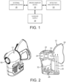
- VBs may be of local, systemic or exogenous origins ( FIG. 1 ).
- ROS Reactive Oxygen Species
- Volatiles of systemic origins are derived from the circulation after originating from metabolic processes elsewhere and dissolving into the blood. Therefore, even non-pulmonary diseases contribute to exhaled VBs, which has successfully been used in the assessment of non-pulmonary malignancies.
- a well known group of systemically originating VOCs are ketone bodies like acetone, acetoacetate and hydroxybutyrate which are oxidized via the Krebs cycle in peripheral tissue as part of glucose metabolism.
- Exogenous VBs can be inhaled or absorbed through the skin. They primarily originate from non-human sources and exist in three categories. Firstly, VBs that are in- and expired without any interaction with the body. A second group of exogenous VBs does interact with human tissue and can be stored inside the body for extensive periods of time 3 . The latter volatiles can therefore serve as potential biomarkers for environmental exposures and buildup of toxins such as the cigarette smoke carcinogen N-Nitrosomine. The third group of exogenous VBs is of (resident) microbial origin (predominantly bacteria, but also fungi and viruses), making them of specific interest when identifying infectious diseases or diseases linked to changes in microbiome.
- exhaled VBs reflect this broad range of (patho)physiological processes they have potential usage in 1. assessment of normal metabolic processes 2. evaluation of environmental exposure 2. therapy stratification 3. monitoring of therapy response 4. monitoring of disease activity and exacerbation prediction 5. Identification and characterisation of micro-organisms in a host. 6. Assessment of host response to micro-organisms 7. Screening for pre-morbid conditions 8. Early detection of disease in asymptomatic subjects. These potential applications are relevant in pulmonary and non-pulmonary diseases.
- US 2014/228699 , WO 2008/060165 , US 3661528 , WO 2015/031838 and WO 2013/026902 disclose different types of apparatus and methods for sampling breath from a patient.
- US 2014/228699 teaches a breath sample capturing device where valves and a pump are used to control collection of gas samples in a sample registry for subsequent analysis.
- WO 2008/060165 teaches use of a venturi sample tube to separate the breath sample into an 'alveolar fraction' and a 'dead space' fraction.
- US 3661528 teaches use of a pressure sensing membrane to actuate a switch to collect samples of expired air in a sampling conduit.
- WO 2015/031848 teaches a pneumatic control system using valves to acquire samples and and WO 2013/026902 teaches a device using valves to collect and analyse NO samples, using a pump to maintain an exhalation flow at a predetermined rate.
- a device for collecting a breath portion from a patient for analysis having the preferred features as set out in the claims.
- a portable microprocessor-controlled breath collection apparatus collects pre-specified fractions of in- or expired air (e.g.,alveolar) VBs into sorbent tubes which are then analyzed by chemical analytical techniques such as Gas Chromatography and Mass Spectrometry and Ion-Mobility Spectrometry (IMS) techniques, and in particular, Field Asymmetric Ion Mobility Spectrometry (FAIMS) techniques for disease diagnosis.
- chemical analytical techniques such as Gas Chromatography and Mass Spectrometry and Ion-Mobility Spectrometry (IMS) techniques, and in particular, Field Asymmetric Ion Mobility Spectrometry (FAIMS) techniques for disease diagnosis.
- IMS Gas Chromatography and Mass Spectrometry and Ion-Mobility Spectrometry
- FIMS Field Asymmetric Ion Mobility Spectrometry
- a measured quantity of breath (or other source of VBs) from a patient is collected, which is subsequently analyzed to detect the presence of VBs markers for assessment of metabolism in health and disease.
- an object of the present invention is to collect one or more samples of the VB's (including VOCs and VICs) in a patient's breath for subsequent in-vitro analysis.
- a purpose for collecting the VOC samples is to facilitate the diagnosis, monitoring and prognosis prediction of inflammatory, infectious and neoplastic diseases, such as lung cancer.
- a highly accurate medical device is provided that is economical, easy to operate, portable and collects breath VBs in a reproducible manner for subsequent use of these biomarkers in a screening or diagnostic test with a high degree of accuracy.
- the present invention provides a device for diagnostic analysis of exhaled VBs and those emitted from tissue and or biological samples for reliable, low cost and non-invasive health care use.
- the device may be provided with:
- Sampling air from one part of the lung is important to localise the breath from the area of the lung that is generating the VOCs.
- the illustrated embodiments discussed below are preferably a software algorithm, program or code residing on computer useable medium having control logic for enabling execution on a machine having a computer processor.
- the machine typically includes memory storage configured to provide output from execution of the computer algorithm or program.
- the term "software” is meant to be synonymous with any code or program that can be in a processor of a host computer, regardless of whether the implementation is in hardware, firmware or as a software computer product available on a disc, a memory storage device, or for download from a remote machine or run in the cloud.
- the embodiments described herein include such software to implement the equations, relationships and algorithms described above.
- One skilled in the art will appreciate further features and advantages of the illustrated embodiments based on the above-described embodiments. Accordingly, the illustrated embodiments are not to be limited by what has been particularly shown and described, except as indicated by the appended claims.
- Breath VBs analysis is a non-invasive procedure. Breath tests are potentially more sensitive than blood tests because the quantity of collected analysis is limited only by the capacity of the breath collection apparatus and the patience of the donor. As such breath VB analysis allows analysis of the metabolic fraction of a large fraction of blood.
- a breath sampler device configured and functional to capture a plurality (e.g., four(4)) samples of the Volatile Biomarkers (VBs) in a patient's in or expired air for later in vitro analysis in a separate laboratory environment (e.g., device 12 shown in the below described figures).
- the present invention breath sampler is designed and functional not to cause an unacceptable hazard to the patient or to the clinical staff using it.
- the electronics and/or software utilized in the sampler device 10 also does not interfere with the patient's vital bodily functions (e.g. breathing). Firstly the sampling mask does not impose any increased breathing resistance.
- the incorporated pressure and CO 2 sensor allow tracing of breathing frequency and efficacy.
- the operator and/or end-user can program an alarm to sound if hyper/hypo-ventilation or hypo-/hyper-capnia occurs.
- the breath sampler device 10 is also configured and functional to be comfortable for the patient while enabling them to breathe either through their mouth and/or through their nose. Additionally, the breath sampler device 10 is designed and configured such that any components of it that are reusable do not come in contact with any biological contamination (bacteria or viruses) in the patient's breath. Further, it is to be appreciated that the breath sampler device 10 is designed and configured to accept a supply of clean air (e.g., from a clean air supply 14) such that any VBs present in the ambient room air are not captured by the device 10. The clean air supply was designed to provide a positive end expiratory pressure for the subject facilitating usage in patients with obstructive and restrictive lung disease.
- a supply of clean air e.g., from a clean air supply 14
- device 10 operates if this supply of clean air has additional oxygen added, up to and including 100% oxygen. This opens the device to use in patients requiring ventilatory support and usage in exposure experiments with spiked gases inhaled by the subjects such as common in diffusion tests.
- the materials of the breath sampler device 10 preferably do not emit any VBs that would affect the later in vitro analysis into the collected breath.
- the breath sampler device 10 captures up to four separate samples of the VBs in the patient's breath, whereafter each sample is readily and accurately identifiable to ensure that it is simple to track which patient it came from.
- the breath sampler device 10 is preferably configurable by the user to select the following for each pair of breath VOC samples: a) the portion of in or expired breath to be sampled (e.g. inspired air, oral air, alveolar breath, bronchiolar breath or total breath); and b) the volume of breath to be sampled for each of these fractions
- the breath sampler device 10 commences breath collection within a predetermined period of time (e.g., 30 seconds) of the patient breathing through it while recording its configuration and designated sensor and actuator readings during breath collection, which is preferably recorded to a central database including any warnings or errors that were generated during the breath collection process.
- the breath sampler device 10 also preferably provides a User Interface via a display unit to guide a device user through the breath collection process, confirm the results of the collection, and provide any warnings messages.
- device 10 is preferably programmable to collect breath from a predetermined portion of in- or expired air in a patient's ventilatory system including nasopharynx, oropharynx, bronchi and alveoli. It is to be understood this is particularly advantageous because specific metabolic processes affect VBs differently in different portions of the breath. For instance, diseases in the alveoli leave VOCs in the last portion of breath exhaled by the patient whereas disease in the bronchioles leave VOCs in breath that is exhaled earlier in the exhalation. Furthermore this allows assessment of inspired air to quantify environmental exposures or standardised provocation and exposure experiments.
- the breath sampler device 10 described herein is preferably readily assembled and disassembled, preferably without the use of tools, or specialty tools and is designed and configured such any components that are reusable do not come in contact with any biological contamination (micro-organisms) in the patient's breath (with the exception being the sample collection tubes 20, in that after a breath collection, the tubes 20 are returned to a laboratory environment where they are fully recycled and cleaned after analysis).
- any biological contamination micro-organisms
- the captured breath samples are preferably shipped for analysis in suitable protective packaging such that the breath samples captured in the tubes 20 do not require refrigeration or freezing during a shipping process.
- the present invention breath sampler device 10 is configured and functional to capture a plurality of patient breath samples (e.g.,1 to 4).
- a plurality of patient breath samples e.g.,1 to 4
- two independent sample controls are captured, each one able to gather up to two samples in parallel with each other.
- the breath sampler device 10 preferably enables the user to configure which part of the breath to collect as follows: 1) how many samples are being collected (0, 1 or 2); 2) whether to use CO 2 or pressure to control the collection; 3) whether to start a collection pump when the control sensor reading is rising or falling; 4) the percentage sensor reading threshold at which to start the collection; 5) whether to stop the pump when the control sensor reading is rising or falling; 6) the percentage sensor reading threshold at which to stop the collection; and 7) the volume of breath to be collected.
- the breath sampler device 10 is preferably configured and functional such that it records the volume collected in each of the sample tube (e.g., sorbent tube 20) and stops the collection at the end of the collection event in which the required volume is reached. For instance, when the breath sampler device 10 is collecting two samples on one sampling channel, the collected breath sample volume is split evenly between the two samples in respective tubes.
- the breath sampler device 10 is preferably preconfigured with settings prescribing, and controlling operation of the device 10 to capture one of alveolar breath, bronchial breath and whole breath.
- FIG. 1 depicts a system for collection of volatile biomarkers, or other animal body, includes a vapor sampling device 10 and a separate detector/analyzer apparatus 12, a clean air supply source 14 and external computing device 16 to be coupled to device 10.
- a vapor sampling device 10 such as a breath sampler
- a clean air supply source 14 to be coupled to device 10.
- external computing device 16 to be coupled to device 10.
- the illustrated embodiments are not to be understood to be limited thereto as they may encompass vapor sampling devices for capturing other vapors from a body such as those that emit from stool and urine, as could be of interest for detecting the presence of colon cancer and prostate cancer.
- FIG. 1 depicts the vapor sampling device 10, detector/analyzer apparatus 12, the clean air supply source 14 and external computing device 16 as separate units, the illustrated embodiments are not to be understood to be limited thereto as they also may encompass a device 10 that incorporates one or more the aforesaid ancillary components.
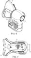
- FIG. 2A depicted is an illustrative embodiment of a breath sampling device 10 (Figure 2A) and its cross-sectional view ( Figure 2B). Additionally views of the device 10 are also shown in Figures 5-7 .
- a vapor sample (e.g., a breath sample), is obtained from the patient via the breath sampling device 10, which is then captured and held in sorbent tubes 20.
- the sorbent tubes 20 are subsequently removed from the breath sampling device 10 and disposed within a detector/analyzer apparatus 12, which is functional to extract the breath sample from the sorbent tube 20 so as to preferably perform a FAIMs analysis thereon to detect VBs in the breath sample to diagnosis lung cancer.
- device 10 in FIG. 2 depicts two (2) sorbent tubes, but it is to be appreciated device 10 may be configured to accommodate any desirable number of sorbent tubes 20.
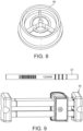
- a sorbent tube 20 used with device 10 is preferably a stainless steel tube which is approximately 76mm long (3") and has a 6.4mm (1 ⁇ 4") diameter containing a sorbent material (e.g., similar to activated carbon) that is specifically designed to absorb VBs and to then re-emit them when the tube 20 is preferably heated in detector/analyzer apparatus 12.
- a sorbent material e.g., similar to activated carbon
- the tubes 20 can be stored for several days and can be shipped via mail and package carriers via preferably a packaging container 40 ( FIG. 9 ).
- the sorbent tubes 20 are preferably glass coated stainless steel tubes packed with absorbent resins (sorbents) designed to trap VBs. When the tubes are subsequently heated in a laboratory environment 12, they release the VBs allowing them to be analyzed. As shown in the Figs. 2 , 5 and 6 , the sorbent tubes 20 push through holes formed in the mask 30 and then connect into the device frame at the bottom portion of the device 10. The sorbent tubes 20 are preferably held via a clamp device to simplify installation and removal from device 10.
- absorbent resins sorbents
- the sorbent tubes 20 are preferably mounted unevenly (e.g., 12 mm spacing at a front portion and 14 mm at a back portion of device 10) so that the block of the sorbent tubes 20 will only fit into the breath capture unit via a designed orientation.
- the sorbent tubes 20 are each preferably hollow glass passivated stainless steel tubes dimensioned to be 89 mm long by 6.4 mm (3.5" by 1/4") OD packed with Tenax GR and Carbograph 5TD, which is the sorbent mix adapted to trap VOCs from a patient's breath. After a breath sample is collected in the tubes 20, they are then sealed, removed from device 10 for subsequent analysis in analytical/detection device 12 wherein the tubes 20 are preferably heated to release the VOCs into the analytical instrument 12. It is to be understood sorbent material is retained at each end of the tube 20 by glass wadding and tightly fitting stainless steel gauze at each end of the tube 20. This ensures that the sorbent material cannot escape from the tube 20.
- each sorbent tube 20 is preferably labelled with a unique serial number and bar code for easy identification and an arrow indicator is preferably provided to show the direction of breath flow. Also shown in Figure 9 is a packaging transport device 40 used to transport tubes 20 removed from the breath sample device 10 to a remotely located analytical/detection device 12 preferably in a laboratory environment.
- device 10 preferably includes a CO 2 and pressure sensor 22, replaceable bacterial filter 24, clean air supply 26, pump(s) 28, a replaceable flexible face mask 30 and a control board 32 for controlling operation of the aforesaid primary components of device 10.
- the functionality of the aforesaid primary components are further discussed below, and the control board 32 is to be understood to include one or more of the system components shown in FIG. 11 (as also described below).
- the CO 2 and pressure sensor 22 preferably monitors breathing adequacy and frequency while pump(s) 28 facilitate passage, and capture, of a portion of a patient's breath in the sorbent tubes 20.
- the sensor 22 is further preferably configured to measure pressure and temperature within the mask 30 as well as CO 2 level in the mask 30.
- the sensor 22 may include a CO 2 sensor 22 component (e.g., such as a readily available Sprint TM IR-W-X type sensor for measuring/detecting a level of CO 2 ) in the mask 30, which may be optionally used for selecting a portion of the patient's breath the device 10 collects in sorbent tubes 20 (as described herein).
- the pressure sensor component of sensor 22 may be a readily available Bosch TM BMP280 combined pressure temperature sensor configured and functional to monitor the pressure in the mask 30, which as described herein is utilized for selecting a predetermined portion of a patient's breath to capture (via the sorbent tubes 20).
- device 10 contains six absolute pressure temperature sensors 22.
- sensor 22 is mounted preferably in the mask 30 to measure the pressure and temperature of the patient's breath.
- Another sensor 22 is preferably mounted on the inlet and on the outlet of each pump 28 and the other sensor(s) monitor ambient pressure and temperature regarding the device 10.
- the aforesaid sensors 22 are utilized such that the mask pressure sensor 22 measures the pressure in the mask, which is utilized to determine the correct points to switch on and off the collection pumps 28 to collect a designated portion of the patient's breath (e.g. alveolar) for capture in the sorbent tubes 20.
- the CO 2 sensor 22 measures the CO 2 level in the patient's breath and is an alternative to pressure for the pump control. It is noted that the difference between the mask pressure sensor and the pump inlet pressure sensor is preferably utilized to detect leaks and blockages in the sorbent tube 20 and associated air passageways, and to detect if a sorbent tube 20 is not properly fitted in device 10.
- the difference between the pump inlet pressure and the pump outlet pressure is also utilized to determine if a pump 28 is working properly, to check for blockages or leaks, and to measure the flow rate through each pump 28.
- the flow rate is integrated to determine the amount of breath collected from a patient.
- the difference between the pump outlet pressure and ambient pressure may also be used to determine if a pump outlet is blocked.
- the sensors 22 have the following specifications: Parameter Value Notes Pressure Range 300 - 1,100 mBar Absolute Accuracy ⁇ 1.0 mBar Over 950 - 1,050 hPa Relative accuracy ⁇ 0.12 mBar Temperature Range -40 to +85 °C Pressure Resolution 0.01 mBar Temperature Resolution 0.1 °C Measurement Rate (slowest mode) 23.1 Hz Worst Case
- the output of the aforesaid sensors 22 is preferably digital such that full measurement specification may be provided to the aforesaid software executing on the external computing device 16.
- the pressure range in the mask 30 was typically ⁇ 500 Pa ( ⁇ 5 mBar) either side of atmospheric.
- the breath sampler device 10 is preferably configured and functional to establish the maximum and minimum pressure in each breathing cycle, and then be able to resolve the maximum and minimum pressure in each breathing cycle.
- the following specifications for mask pressure measurement is preferably:
- the relative accuracy is the accuracy with which the mask pressure sensor 22 can measure the difference between the pressure in the mask 30 and the pressure in the room (as measured by the environmental pressure sensor) once the offset between the two has been corrected for (if required), preferably with the mask 30 not fitted to the patient and the external air supply 14 switched off.
- illustrative specifications include: Parameter Value Measurement Range 0 - 20% CO2 Absolute Accuracy ⁇ 70 ppm ⁇ 5% of reading Temperature Range 0 to +50 °C Operating Pressure Range 950 mbar to 10 bar Measurement Rate 20 Hz Resolution 0.0001%
- the output of the CO 2 sensor 22 is preferably in ppm such that known conversion factors are required to convert acquired data to percent CO 2 . It is also noted that a requirement for CO 2 sensing is that the device 10 preferably reads mask CO 2 in the range 0 - 10% CO 2 at 5Hz to a minimum resolution of 0.05% and to an overall accuracy of ⁇ 0.5% CO 2 over the normal breath range of 0 - 5% CO 2 .
- the CO 2 concentration is expected to be less than 0.1% in the input air and approximately 4.5% in the exhaled breath.
- the breath sampler device 10 is preferably configured and functional to establish the minimum and maximum CO 2 levels for each breathing cycle and to resolve between the minimum and maximum CO 2 levels for each breathing cycle.
- the device has a detection rate as follows:
- the biological filter 24 is preferably mounted in the mask 30 and is configured and constructed to ensure that all biological contamination in the patient's breath (e.g., bacteria or viruses) come in contact with the mask 30 and the filter 24 (both of which are one-time use) and the sorbent tubes 20 (which are preferably baked at around 300°C before each patient).
- the face mask 30 is preferably formed of silicone material designed for both patient comfort, and to contact the sorbent tubes 20, the biological filter 24 and a portion of the housing for device 10 (as shown in FIG. 2 ). It is noted the mask 30 does not obscure a patient's vision while permitting the patient to breathe through their mouth and/or nose.
- device 10 is fitted with a clean air supply valve 26 which intakes clean air from an external source 14 so as to avoid contamination of the patient's breath with the ambient air surrounding device 10 and the patient.
- device 10 is configured to contain a pair of sorbent tubes 20, wherein each sorbent tube 20 may be independently gated to collect different breath fractions during a same breath collection event.
- the sorbent tubes 20 are to contain patient breath samples which are to be analyzed offline (separate from device 10) on numerous testing platforms, including (and not limited to) GC-MS and GC-FAIMS platforms in a laboratory environment 12.
- device 10 may be coupled directly to a detector/analyzer apparatus 12 thus obviating the need to separately remove the sorbent tubes 20. It is to be further appreciated that four calibrated orifice plates may preferably be provided in device 10 to balance the flow through the sorbent tubes 20 ( FIG. 7 ).
- two computer controlled pumps 28 are provided in the illustrated embodiment, each configured to draw a patient's breath through the sorbent tubes 20 (e.g., one pump 28 for each pair of tubes 20).
- Each pump 28 preferably has an absolute pressure sensor mounted directly upstream of it and downstream of it to determine the flow rate through the pump 28 and to detect leaks and blockages (as mentioned above).
- a microprocessor is preferably provided in the control board 32 to provide a level of control of the pumps 28 and to read sensors and to provide this information over a USB connection 70 ( FIG. 7 ) to preferably an externally computing device 16 ( FIG. 1 ) (e.g., such as a desktop, laptop, tablet or computing type device).
- USB connection 70 further facilities electrical power delivery to the device 10.
- software is preferably executing on the aforementioned external computing device 16 to control data sampling and to record results regarding patient breath samples.
- the aforementioned microprocessor 32 is coupled to associated drive electronics configured to operate the pumps 28, read the sensors 22 and communicate such data to said external computing device 16.
- the device 10 of the illustrated embodiment is preferably controlled by software executing on an external computing device 16.
- the software it is to be understood its execution affects communication via the USB connection 70 with the pumps 28 functional to communicate with and read the sensors provided in the device 10 (e.g., sensors 22); control the pumps 28 to turn on and off at the designated times to collect a selected portion of a patient's breath; track an amount of breath collected in each sorbent tube 20 and stop collection when an ample amount of patient's breath has been collected; and guide an operator/user (e.g., medical professional), preferably via a user display or GUI provide on the external computing device 16 or device 10, through a breath collection process with the provision of appropriate feedback.
- an operator/user e.g., medical professional
- each pump 28 preferably has a Bosch TM BMP 280 pressure sensor mounted upstream and just downstream of it, which pressure sensors are used to determine the flow rate through the pump 28 and to detect whether the pump 28 and/or a sorbent tube 20 is leaking or blocked.
- the pumps 28 are preferably configured to exhaust to the ambient air surrounding device 10.
- orifice plates as shown in FIG. 7 ) having small accurate flow restrictors are provided on the device 10 configured to provide an accurate flow resistance positioning the pumps 28 into a correct portion of their operating curve to mitigate the variation in the flow between the sorbent tubes 20 on the pumps 28 caused by differences in their flow resistance.
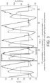
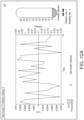
- FIG. 3 illustrates CO 2 concentration, pressure and pump-enable traces from a collection event with a 50% on/off gating algorithm using pressure.
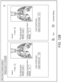
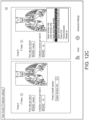
- FIG. 4A illustrates GC-MS results from breath samples including retention time matched and NIST identification while FIG. 4B illustrates GC-FAIMS quality control.
- a patient fits the disposable silicone mask 30 to the patient's face preferably configured to allow them to breathe through their nose and/or mouth.
- a head strap is preferably fitted to the face mask 30 to hold the unit in place on the patient.
- the biological filter 24 is preferably provided at the outlet portion of the mask 30 designed to prevent contamination from the patient's breath coming in contact with the breath sampler device 10.
- a clean air supply 14 via valve 26) enables the patient to breath air that is preferably free of VBs that might be present in the ambient room air surrounding device 10, as these would contaminate the breath sample.
- the outlet portion of the mask 30 includes a one-way valve 80 ( FIG.
- valve 80 permitting the patient to breathe out to the room while inhaling (scrubbed) clean air, via its coupling to a clean air supply source 14 (via valve 26).
- the aforementioned one-way valve 80 is preferably a mechanical unit consisting of a plastic membrane that permits air out of the device 10 but does not permit air in.
- the breath sampler device 10 preferably starts the collection within a predetermined time from device activation (e.g., 30 seconds) preferably triggered by a patient breathing through it and subsequently confirms to the medical professional attending operation of the device 10 that the collection process is complete.
- a medical professional is able to prescribed a maximum time for the patient breath collection, and if the required volume of breath has not be collected within the prescribed time, collection ceases (e.g., an error message may be displayed).
- the breath flow rate through the sorbent tubes 20 it is to be understood if it is too slow the patient then has to spend too long a time breathing into the mask 30, and if the breath flow rate is too fast then the most volatile chemicals are likely lost by not being captured within the sorbent tubes 20.
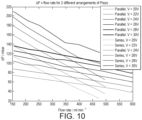
- Test data has demonstrated that 200 - 300 mL/min is an optimum rate through each tube 20 whereby the flow rate generates a pressure drop across the sorbent tube 20 of 42.5 mBar. It is noted that the collected breath volume is a compromise between patient comfort and having enough time to collect VOCs to analyze. In accordance with an illustrated embodiment, 1.2 litres on each tube 20 is optimal, requiring a test length of approximately 6 minutes. It is noted though that the actual collected volume and flow rate may be chosen by a medical professional user of device 10.
- each pump has a flow characteristic as shown in Figure 10 . It is to be appreciated that for optimum collection, the sorbent tubes 20 require a flow rate of up to 300 mL/min each, thus each pump 28 should deliver up to 600 mL/min. Additionally as shown in the pump flow characteristics of Figure 10 , each pump 28 preferably has two separate pump units that can be plumbed in series or in parallel, wherein the graph depicted in Figure 10 shows a parallel connection is preferred.
- the breath sampler device 10 it is preferably required to collect 95% of the patient's breath that the medical professional expects and no more than 5% of other breath.
- the portion of a patient's breath is collected and determined by when in each breath cycle the sample collection pump 28 is turned on and off. The accuracy of this is determined by: i) the accuracy of the mask pressure or CO 2 measurement; ii) the latency in reading the sensors 22; and iii) the latency in switching the pumps 28 on or off.
- typical breathing rates in adults are 16 - 20 breaths per minute, extending to 10 - 30 breaths per minute for patient's over 80 years of age.
- the breath sampler device 10 is preferably configured and adapted to operate from 8 - 30 breaths per minute, corresponding to a breath every 2.0 - 7.5 seconds.
- 95% of the correct breath is preferably collected and only 5% of incorrect requires a timing accuracy of ⁇ 2.5% of a breath for both the start and end of breath collection.
- execution of the firmware embedded in device 10 requires that: the firmware reads the control sensor (mask pressure or CO 2 ); sends readings to the externally coupled computing device 16 (preferably via USB connection, or wireless connection).
- the PC software executing on the externally connected computing device 16 reads the aforesaid captured data to determine the time to switch the state of the pump between on/off, which software also sends a message to the device embedded firmware to execute operation of the pumps 28.
- the device is configured and functional to derive the flow rate through each sample collector preferably in the range 0 - 300 mL/min at 5Hz with an accuracy of ⁇ 5% to meet the requirement that the volume of breath collected is accurate to ⁇ 5%.
- the flow rate is preferably determined by measuring the pressure drop across the pumps 28.
- the flow accuracy is therefore generated by the accuracy of the pressure measurement and the accuracy of the flow calibration.
- the approximate total error expected between the two pressure readings (pump upstream and pump downstream) is ⁇ 2.0 mBar (as indicated above) which is equivalent to a flow measurement error of ⁇ 0.67 mL/min or ⁇ 0.34% of the expected flow rate of around 200 mL/min.
- the flow path for the breath samples (air) through the sorbent tubes 20 is as follows: first, the collection of breath (air) commences in the mask 30 where there is preferably a pressure sensor (P mask ). The collected air from the patient then goes through the sorbent tubes 20, and then through an orifice plate ( Figure 7 ). Pressure is measured upstream of the pump 28 (P up ), which passes through the pump 28. The pressure is also measured downstream of the pump (P Down ) and then vented to atmosphere.
- P mask a pressure sensor
- the pressure rise across each pump 28 is a function of the flow through it (as mentioned above) and as a result by comparing the pressure rise across a pump 28 with that expected for the voltage applied it facilities the detection of air blockages in device 10. For example, at 24V the expected pressure rise is around 80 mBar at 500 mL/min (the expected flow), but when blocked, the pressure rise will be 110 mBar. The pressure sensors can measure the pressure rise to ⁇ 0.24 mBar. It is noted this same method is used to detect leaks. That is, if there is a leak where a sorbent tube 20 connects to the breath capture unit (e.g., detected by the change in the pressures). Using this process, the differences in the flow resistance of a sorbent tube 20 compared with another tube 20 connected to the same pump 28 is thus evident.
- each tube 20 has a Lee orifice plate in series with it and the pressure drop across these plates balances the flow between the two tubes 20 such that approximately a 10% difference in flow resistance only causes a 4.8% error in the flow in that tube and a 0.9% error in the other tube.
- device 10 is configured and functional to detect when the wrong number of sorbent tubes 20 has been fitted as the flow rate will be half (or twice) that is expected, this pressure drop will be incorrect.
- the device 10 performs regarding verification that the patient breath sample it has collected is correct.
- the following device readings are monitored to determine whether they reside within predefined limits: 1) the patient's breathing rate; 2) the CO 2 level during exhalation; 3) the pressure during inhalation; and 4) the pressure during exhalation.
- the device 10 preferably performs a routine that checks that the pumps 28 have been turned on and off correctly throughout the collection and that there are no leaks or blockages in the breath collection path and whether an air blockage present in the sample collection path which would compromise the capture of patient breath samples.
- control board 32 and associated computing components and systems used in conjunction with operation of device 10.
- FIG. 11 shown is a computer system 200, the components of which may be included in device 10 (e.g., control board 32).
- the components of system 200 may include, but are not limited to, one or more processors or processing units 216, a system memory 228, and a bus 218 that couples various system components including system memory 228 to processor 216.
- Bus 218 represents one or more of any of several types of bus structures, including a memory bus or memory controller, a peripheral bus, an accelerated graphics port, and a processor or local bus using any of a variety of bus architectures.
- bus architectures include Industry Standard Architecture (ISA) bus, Micro Channel Architecture (MCA) bus, Enhanced ISA (EISA) bus, Video Electronics Standards Association (VESA) local bus, and Peripheral Component Interconnect (PCI) bus.
- Computing device 200 typically includes a variety of computer system readable media. Such media may be any available media that is accessible by device 200, and it includes both volatile and non-volatile media, removable and non-removable media.
- System memory 228 can include computer system readable media in the form of volatile memory, such as random access memory (RAM) 230 and/or cache memory 232.
- Computing device 200 may further include other removable/non-removable, volatile/non-volatile computer system storage media.
- storage system 234 can be provided for reading from and writing to a non-removable, non-volatile magnetic media and/or Solid State Drives (SSD) (not shown and typically called a "hard drive”).
- SSD Solid State Drives
- a magnetic disk drive for reading from and writing to a removable, non-volatile magnetic disk
- an optical disk drive for reading from or writing to a removable, non-volatile optical disk such as a CD-ROM, DVD-ROM or other optical media
- each can be connected to bus 218 by one or more data media interfaces.
- Memory 228 may include at least one program product having a set (e.g., at least one) of program modules that are configured to carry out the functions of embodiments of device 10 described herein.
- Program/utility 240 having a set (at least one) of program modules 215, such as underwriting module, may be stored in memory 228 by way of example, and not limitation, as well as an operating system, one or more application programs, other program modules, and program data. Each of the operating system, one or more application programs, other program modules, and program data or some combination thereof, may include an implementation of a networking environment.
- Program modules 215 generally carry out the functions and/or methodologies of embodiments of the invention as described herein.
- Device 200 may also communicate with one or more external devices 214 such as a keyboard, a pointing device, a display 224, etc.; one or more devices that enable a user to interact with computing device 200; and/or any devices (e.g., network card, modem, etc.) that enable computing device 200 to communicate with one or more other computing devices. Such communication can occur via Input/Output (I/O) interfaces 222. Still yet, device 200 can communicate with one or more networks such as a local area network (LAN), a general wide area network (WAN), and/or a public network (e.g., the Internet) via network adapter 220. As depicted, network adapter 220 communicates with the other components of computing device 200 via bus 218.
- LAN local area network
- WAN wide area network
- public network e.g., the Internet
- device 200 includes, but are not limited to: microcode, device drivers, redundant processing units, external disk drive arrays, RAID systems, tape drives, and data archival storage systems, etc.
Description
- The present invention relates generally to a medical device and protocols to facilitate diagnosis of medical conditions based on breath and body volatile biomarker analysis, and in particular, to an apparatus, system and method that collects volatile biomarkers for assessment of health and disease diagnosis, monitoring and assessment of prognosis.
- The metabolome is the aggregate of small molecules that originate from metabolic processes throughout the body. Metabolomic analysis is appealing for biomedical applications as relatively small changes in gene-expression or protein activity can have a profound effect on the concentrations of downstream metabolites. A significant fraction of these metabolites are volatile. These biomarkers are of specific interest in health and disease as they are excreted through breath, urine, feces and skin providing non-invasive access. Volatile biomarkers (VBs) consist of both volatile organic compounds (VOCs) and Volatile inorganic compounds (VICs). Examples of VBs implicated in health and disease include alkanes, alkenes, acetone, isoprene, NO, CO and aldehydes.
- Any change in the function of an organism changes cellular metabolism by definition. Consequently this affects the metabolome and its volatile fraction. The resulting changes in VBs may therefore serve as biomarkers for assessment of a wide range of normal physiological and pathophysiological processes.
- The rate at which VBs are exhaled is the net effect of several interacting (bio)chemical processes; intra and extra-cellular degradation, solubility of the compound in extracellular fluid, fat and blood, the affinity with extracellular matrix and carrier proteins, the concentration gradient between the alveolar and bronchial air, the vapor pressure and alveolar ventilation. This results in a chemical equilibrium of a given compound between breath, blood and fat which can be described by that substance's physiochemical partition constant.
- To date several thousands of individual VBs have been identified generally occurring in the parts per million / parts per billion range. VBs may be of local, systemic or exogenous origins (
FIG. 1 ). - In breath locally produced compounds diffuse directly into alveoli or the airway lumen along the respiratory tract. An example is the biological mechanism behind VOC formation in the presence of Reactive Oxygen Species (ROS). ROS are responsible for increased levels of oxidative stress associated with disease in general. ROS drive cell wall lipid peroxidation resulting in production of ethane and n-pentane. These substances show only low solubility in blood and are therefore excreted into breath within minutes of their formation in tissues. Hence, exhaled concentrations of ethane and n-pentane can be used to monitor the degree of oxidative damage in the body.
- Volatiles of systemic origins are derived from the circulation after originating from metabolic processes elsewhere and dissolving into the blood. Therefore, even non-pulmonary diseases contribute to exhaled VBs, which has successfully been used in the assessment of non-pulmonary malignancies. A well known group of systemically originating VOCs are ketone bodies like acetone, acetoacetate and hydroxybutyrate which are oxidized via the Krebs cycle in peripheral tissue as part of glucose metabolism.
- Exogenous VBs can be inhaled or absorbed through the skin. They primarily originate from non-human sources and exist in three categories. Firstly, VBs that are in- and expired without any interaction with the body. A second group of exogenous VBs does interact with human tissue and can be stored inside the body for extensive periods of time3. The latter volatiles can therefore serve as potential biomarkers for environmental exposures and buildup of toxins such as the cigarette smoke carcinogen N-Nitrosomine. The third group of exogenous VBs is of (resident) microbial origin (predominantly bacteria, but also fungi and viruses), making them of specific interest when identifying infectious diseases or diseases linked to changes in microbiome. Since exhaled VBs reflect this broad range of (patho)physiological processes they have potential usage in 1. assessment of normal metabolic processes 2. evaluation of environmental exposure 2. therapy stratification 3. monitoring of therapy response 4. monitoring of disease activity and exacerbation prediction 5. Identification and characterisation of micro-organisms in a host. 6. Assessment of host response to micro-organisms 7. Screening for pre-morbid conditions 8. Early detection of disease in asymptomatic subjects. These potential applications are relevant in pulmonary and non-pulmonary diseases.
- However, though analysis of body fluids (blood, sputum, urine) for disease diagnoses and monitoring is routine clinical practice, human breath analysis methodologies that exploit the non-invasive nature of such diagnoses are still under-developed and have not been adopted in clinical practice. Reasons underlying this lack of adoption include:
- 1. Reproducibility of technology: Most techniques used to date show inadequate inter and intra device reproducibility to allow deployment.
- 2. Technology sensitivity: VBs, especially VOCs typically occur in the ppb ppt range, many analytical systems do not have this sensitivity.
- 3. Selectivity of technology: As the composition of VBs is complex a system needs to be selective in detection of target compounds.
- 4. Unreliable sample collection: Sample collect is generally poorly standardised and validated.
- 5. Technology costs: Costs of classical chemical analytical instruments are prohibitive for deployment of a VB based test.
-
US 2014/228699 ,WO 2008/060165 ,US 3661528 ,WO 2015/031838 andWO 2013/026902 disclose different types of apparatus and methods for sampling breath from a patient.US 2014/228699 teaches a breath sample capturing device where valves and a pump are used to control collection of gas samples in a sample registry for subsequent analysis. -
WO 2008/060165 teaches use of a venturi sample tube to separate the breath sample into an 'alveolar fraction' and a 'dead space' fraction.US 3661528 teaches use of a pressure sensing membrane to actuate a switch to collect samples of expired air in a sampling conduit.WO 2015/031848 teaches a pneumatic control system using valves to acquire samples and andWO 2013/026902 teaches a device using valves to collect and analyse NO samples, using a pump to maintain an exhalation flow at a predetermined rate. - In accordance with the present invention, there is provided a device for collecting a breath portion from a patient for analysis having the preferred features as set out in the claims.
- The purpose and advantages of the below described illustrated embodiments will be set forth in and apparent from the description that follows. Additional advantages of the illustrated embodiments will be realized and attained by the devices, systems and methods particularly pointed out in the written description and claims hereof, as well as from the appended drawings.
- To achieve these and other advantages and in accordance with the purpose of the illustrated embodiments, in one aspect, a portable microprocessor-controlled breath collection apparatus collects pre-specified fractions of in- or expired air (e.g.,alveolar) VBs into sorbent tubes which are then analyzed by chemical analytical techniques such as Gas Chromatography and Mass Spectrometry and Ion-Mobility Spectrometry (IMS) techniques, and in particular, Field Asymmetric Ion Mobility Spectrometry (FAIMS) techniques for disease diagnosis.
- Described is an apparatus, system and method which collects and analyses biomarkers for the assessment of physiological and pathophysiological processes in health and disease (e.g. infectious, inflammatory and neoplastic disease)in an organism, including a human (hereinafter collectively referred to as a "patient"). In one or more illustrated embodiments, a measured quantity of breath (or other source of VBs) from a patient is collected, which is subsequently analyzed to detect the presence of VBs markers for assessment of metabolism in health and disease.
- Therefore, it is to be appreciated that an object of the present invention is to collect one or more samples of the VB's (including VOCs and VICs) in a patient's breath for subsequent in-vitro analysis. A purpose for collecting the VOC samples is to facilitate the diagnosis, monitoring and prognosis prediction of inflammatory, infectious and neoplastic diseases, such as lung cancer.
- Accordingly, a highly accurate medical device is provided that is economical, easy to operate, portable and collects breath VBs in a reproducible manner for subsequent use of these biomarkers in a screening or diagnostic test with a high degree of accuracy.
- The present invention provides a device for diagnostic analysis of exhaled VBs and those emitted from tissue and or biological samples for reliable, low cost and non-invasive health care use.
- The device may be provided with:
- GC-FAIMS heated zone to minimize condensing at end of column
- Splits and purge for breath samples to deal with moisture
- Set up of cold trap above freezing to deal with moisture
- Selection of the Tenax / Carbotrap sorbent to cover the range of chemicals that we expect to find in breath while ensuring that both sorbents are hydrophobic so that the repel the high level of water vapour found in breath.
- Rationale for collecting multiple breath fractions
- Potential to collect inspired air for exposure assessment
- Potential to collect inspired air for correction against environmental VBs
- Potential to collect volatile biomarkers originating from micro-organisms
- Potential to use air supply to load inhaled air with components to perform wash-out and/or exposure experiments.
-
- Use of a pressure sensor and CO2 sensor in the device to track the patient's breathing pattern.
- Use these algorithms to be able to select breath from a particular portion of the air from the respiratory system - examples of this include total breath, total breath but without mouth air, just air from the upper airway, just breath from the lower airway, combined breath from the upper and lower airways, air from the oropharynx and nasopharynx as well as air coming from the stomach.
- Sampling air from one part of the lung is important to localise the breath from the area of the lung that is generating the VOCs.
- Sampling different parts of the breath in order to provide a control which can be used to eliminate exogenous peaks
- Sampling parts of the breath which exclude the volume from the mouth in order to reduce exogenous peaks
- Using pumps based on high frequency piezo technology which can be switched on and off fast enough to sample a part of breath
- Using fixed flow resistance apertures to reduce the effect of variation in sampling tube resistance
- Sampling the inhaled air in order to correct for exogenous compounds
- Create a detailed log file of all the data collected during the breath collection for later analysis to check that the breath collection was valid.
- Use two separate sampling channels so that different portions of the same patient's breath can be compared and the differences between the two samples and their similarities can be used in disease diagnosis.
- Have the ability to run zero, one or two sorbent tubes on each pump so that a wide range of use cases can be covered. This includes the ability to analyse the samples from each sample type on both MS-FAIMS and GC-MS.
-
- Monitoring pressure to calculate the point in a breath that originates in a particular part of the lung in order to trigger a pump activation
- Using the first or second differential of the pressure to calculate the point in a breath that originates in a particular part of the lung in order to trigger a pump activation
- Scaling the pressure or differential pressure thresholds according the breathing pattern of a particular patient
- Using a user definable offsets on the learned thresholds to enable a small amount of overlap in sections of breath to be applied
- Scaling any user definable offsets with the magnitude of the breathing so they behave the same across different patients
- Using a number of previous breaths to actively change the calculated points over time to account for changes in the patients breathing over time
- Applying filters or trimming outliers to learnt breath data in order to exclude anomalous breathing patterns (talking, coughing or sudden intakes of breaths) before using the pressure or first differential of the pressure to calculate the thresholds
- Applying a running window of a fixed number of the most recent breaths to account for long term trends when sampling (patient relaxing and getting used to the sampling)
- Using hard limits on the time an individual breath is sampled for and the pressure difference across a breath to minimise the effect of an anomalous breathing pattern
- Using CO2 to calculate the point in a breath that originates in a particular part of the lung in order to trigger a pump activation
- Using the point of maximum CO2 to identify a particular part of the lung in order to trigger a pump activation
- Using the pressure at the point of maximum CO2 as the trigger for a pump activation
- If the CO2 is lagging the breath due to its response time calculating the lag and using to find the correct pressure at the point of maximum CO2
- If the CO2 is lagging the breath due to its response time using the end of the breath to calculate the lag and using this to find the correct pressure at the point of maximum CO2
- Monitoring the patients breathing rate and providing feedback to the user of the software in order to optimise the breath collection
- Monitoring the pressure in the mask in order to detect a poorly fit mask and providing feedback to the user of the software if detected
- Compare the pressure drop inside the system to generate a particular flow rate to expected pump behaviour over time in order to detect a system leak or pump failure
-
- The CO2 sensor can be used to monitor the adequacy of the patients breathing and set appropriate thresholds to abort sampling procedure in the case of hyper or hypocapnia.
- The pressure sensor can be used to monitor breathing frequency and set appropriate thresholds to abort sampling in the case of hypo or hyperventilation.
- The air supply of the apparatus can be used to provide the patient with additional oxygen during sampling if medically indicated.
-
- Using a cold trap that uses the same sorbents as the sampling tubes to ensure that it accurately captures the VOCs found in the tube.
- Holding the cold trap at a temperature above freezing so that water does not freeze on the cold trap.
- Splitting the sample to only pass some of it through the analytical instrument to reduce the impact of water damage and to avoid overloading the instrument.
- Load internal standards onto the sorbent tubes or onto the cold trap to enable internal QC check on the analytical measurement.
- Use of a non-polar GC column to reduce interaction with water in the stationary phase and to provide a more robust method when running high volumes of samples.
- Correction of retention times through the GC column by regularly testing known QC mixtures on sorbent tubes between running the breath samples and then measuring the time taken for these QC compounds to pass through the GC column and using this to correct the data from later breath samples.
- Because a FAIMS system such as manufactured by Owlstone Inc. can scan very quickly then continuously scan multiple DF values while the breath sample is passing through the GC column to improve the resolution of the analytes. Use the additional separation available from the FAIMS system to separate VOCs that take the same time to pass through the GC column.
- Running FAIMS at high temperature to prevent water and other compounds condensing at the FAIMS entrance. This improves the quality of the resulting spectra and prevents damage to the GC column.
- Run breath samples on both the GC-FAIMS and the GC-MS and combine the data from both platforms to generate the cancer classifier. This is powerful because there are some VOCs where the GC-FAIMS is better at detecting them and some where the GC-MS is better.
- Check the system by running a homologous series of compounds through to check both the GC retention times and the FAIMS performance. This is particularly important as the FAIMS can operate at a wide range of temperatures.
-
- Drawing a section of breath onto a cold trap in order to concentrate the sample before measurement on a DMS system
- Drawing different sections of breath onto a number of cold traps in order to concentrate the sample before measurement on a DMS system in sequence
- As well as samples of breath drawing in ambient air onto a trap in order to eliminate exogenous compounds
- Using a micro GC or short air compatible GC on a DMS system to provide basic pre-separation
- Running at low temperature isothermal GC conditions to prevent degradation of breath compounds
- Using a metal-organic framework as a sorbent to allow air to be used as the carrier gas
- Re-collecting sample and repeating with different thermal desorption profile or GC temperature to provide additional separation
- Running recollected samples only if certain peak/feature/pattern is observed - optimise for fast negative (all clear) method
- Combining with a NDIR/FTIR measurement to provide additional chemical information
- Sampling directly onto a DMS system and using Acetone or other high intensity compound as the marker of the section of breath. Using the DMS as the selector for the part of breath and loading a cold trap or sorbent tube. When collect is complete desorb the pre-concentrated sample back into the DMS
- The accompanying appendices and/or drawings illustrate various non-limiting, example, inventive aspects in accordance with the present disclosure:
-
Figure1 illustrates a system level overview of an embodiment of the present invention; - Figures 2A and 2B illustrate a perspective (Figure 2A) and cross-sectional view (Figure 2B) of a breath sampler device of an embodiment of the present invention;
-
Figures 3 and4 depict analysis of test data regarding capture of a patient's breath using the device ofFigure 2 and system ofFigure 1 ; -
Figures 5-7 illustrate various perspective view of the device ofFigure 2 ; -
Figure 8 illustrates a one-way valve used in the device ofFigure 2 ; -
Figure 9 illustrates a perspective view of a sorbent tube and a packaging container used to transport the sorbent tube used with the device ofFigure 2 ; -
Figure 10 illustrates a chart depicting data regarding operation of pumps used in the device ofFigure 2 ; and -
Figure 11 illustrates an example computer device/system which may be used in the device ofFigure 2 ; -
Figure 12 illustrates a user interface provided by the computer device/system and various settings, options and guidance provided to the user. - The illustrated embodiments are now described more fully with reference to the accompanying drawings wherein like reference numerals identify similar structural/functional features. The illustrated embodiments are not limited in any way to what is illustrated as the illustrated embodiments described below are merely exemplary, which can be embodied in various forms, as appreciated by one skilled in the art. Therefore, it is to be understood that any structural and functional details disclosed herein are not to be interpreted as limiting, but merely as a basis for the claims and as a representation for teaching one skilled in the art to variously employ the discussed embodiments. Furthermore, the terms and phrases used herein are not intended to be limiting but rather to provide an understandable description of the illustrated embodiments.
- Unless defined otherwise, all technical and scientific terms used herein have the same meaning as commonly understood by one of ordinary skill in the art to which this invention belongs. Although any methods and materials similar or equivalent to those described herein can also be used in the practice or testing of the illustrated embodiments, exemplary methods and materials are now described.
- It must be noted that as used herein and in the appended claims, the singular forms "a", "an," and "the" include plural referents unless the context clearly dictates otherwise. Thus, for example, reference to "a stimulus" includes a plurality of such stimuli and reference to "the signal" includes reference to one or more signals and equivalents thereof known to those skilled in the art, and so forth.
- It is to be appreciated the illustrated embodiments discussed below are preferably a software algorithm, program or code residing on computer useable medium having control logic for enabling execution on a machine having a computer processor. The machine typically includes memory storage configured to provide output from execution of the computer algorithm or program.
- As used herein, the term "software" is meant to be synonymous with any code or program that can be in a processor of a host computer, regardless of whether the implementation is in hardware, firmware or as a software computer product available on a disc, a memory storage device, or for download from a remote machine or run in the cloud. The embodiments described herein include such software to implement the equations, relationships and algorithms described above. One skilled in the art will appreciate further features and advantages of the illustrated embodiments based on the above-described embodiments. Accordingly, the illustrated embodiments are not to be limited by what has been particularly shown and described, except as indicated by the appended claims.
- Breath VBs analysis is a non-invasive procedure. Breath tests are potentially more sensitive than blood tests because the quantity of collected analysis is limited only by the capacity of the breath collection apparatus and the patience of the donor. As such breath VB analysis allows analysis of the metabolic fraction of a large fraction of blood.
- What is described below, and in accordance with one or more illustrative embodiments, is a breath sampler device (e.g. device 10 shown in the below described figures) configured and functional to capture a plurality (e.g., four(4)) samples of the Volatile Biomarkers (VBs) in a patient's in or expired air for later in vitro analysis in a separate laboratory environment (e.g., device 12 shown in the below described figures). The present invention breath sampler is designed and functional not to cause an unacceptable hazard to the patient or to the clinical staff using it. The electronics and/or software utilized in the sampler device 10 also does not interfere with the patient's vital bodily functions (e.g. breathing). Firstly the sampling mask does not impose any increased breathing resistance. The incorporated pressure and CO2 sensor allow tracing of breathing frequency and efficacy. The operator and/or end-user can program an alarm to sound if hyper/hypo-ventilation or hypo-/hyper-capnia occurs.
- The breath sampler device 10 is also configured and functional to be comfortable for the patient while enabling them to breathe either through their mouth and/or through their nose. Additionally, the breath sampler device 10 is designed and configured such that any components of it that are reusable do not come in contact with any biological contamination (bacteria or viruses) in the patient's breath. Further, it is to be appreciated that the breath sampler device 10 is designed and configured to accept a supply of clean air (e.g., from a clean air supply 14) such that any VBs present in the ambient room air are not captured by the device 10. The clean air supply was designed to provide a positive end expiratory pressure for the subject facilitating usage in patients with obstructive and restrictive lung disease. Furthermore, device 10 operates if this supply of clean air has additional oxygen added, up to and including 100% oxygen. This opens the device to use in patients requiring ventilatory support and usage in exposure experiments with spiked gases inhaled by the subjects such as common in diffusion tests. The materials of the breath sampler device 10 preferably do not emit any VBs that would affect the later in vitro analysis into the collected breath. In accordance with a preferred embodiment, the breath sampler device 10 captures up to four separate samples of the VBs in the patient's breath, whereafter each sample is readily and accurately identifiable to ensure that it is simple to track which patient it came from.
- With regards to captured breath samples, the breath sampler device 10 is preferably configurable by the user to select the following for each pair of breath VOC samples: a) the portion of in or expired breath to be sampled (e.g. inspired air, oral air, alveolar breath, bronchiolar breath or total breath); and b) the volume of breath to be sampled for each of these fractions In accordance with a preferred embodiment, the breath sampler device 10 commences breath collection within a predetermined period of time (e.g., 30 seconds) of the patient breathing through it while recording its configuration and designated sensor and actuator readings during breath collection, which is preferably recorded to a central database including any warnings or errors that were generated during the breath collection process. During this initial time period the environmental VOCs are washed out and the breath collection software. The breath sampler device 10 also preferably provides a User Interface via a display unit to guide a device user through the breath collection process, confirm the results of the collection, and provide any warnings messages.
- In accordance with the illustrated embodiments described herein, device 10 is preferably programmable to collect breath from a predetermined portion of in- or expired air in a patient's ventilatory system including nasopharynx, oropharynx, bronchi and alveoli. It is to be understood this is particularly advantageous because specific metabolic processes affect VBs differently in different portions of the breath. For instance, diseases in the alveoli leave VOCs in the last portion of breath exhaled by the patient whereas disease in the bronchioles leave VOCs in breath that is exhaled earlier in the exhalation. Furthermore this allows assessment of inspired air to quantify environmental exposures or standardised provocation and exposure experiments.
- The breath sampler device 10 described herein is preferably readily assembled and disassembled, preferably without the use of tools, or specialty tools and is designed and configured such any components that are reusable do not come in contact with any biological contamination (micro-organisms) in the patient's breath (with the exception being the sample collection tubes 20, in that after a breath collection, the tubes 20 are returned to a laboratory environment where they are fully recycled and cleaned after analysis).
- The captured breath samples are preferably shipped for analysis in suitable protective packaging such that the breath samples captured in the tubes 20 do not require refrigeration or freezing during a shipping process.
- In accordance with the described illustrated embodiments (and as mentioned above), the present invention breath sampler device 10 is configured and functional to capture a plurality of patient breath samples (e.g.,1 to 4). Preferably, two independent sample controls are captured, each one able to gather up to two samples in parallel with each other. For instance, for each sample control, the breath sampler device 10 preferably enables the user to configure which part of the breath to collect as follows: 1) how many samples are being collected (0, 1 or 2); 2) whether to use CO2 or pressure to control the collection; 3) whether to start a collection pump when the control sensor reading is rising or falling; 4) the percentage sensor reading threshold at which to start the collection; 5) whether to stop the pump when the control sensor reading is rising or falling; 6) the percentage sensor reading threshold at which to stop the collection; and 7) the volume of breath to be collected.
- The breath sampler device 10 is preferably configured and functional such that it records the volume collected in each of the sample tube (e.g., sorbent tube 20) and stops the collection at the end of the collection event in which the required volume is reached. For instance, when the breath sampler device 10 is collecting two samples on one sampling channel, the collected breath sample volume is split evenly between the two samples in respective tubes. In accordance with a preferred embodiment, the breath sampler device 10 is preferably preconfigured with settings prescribing, and controlling operation of the device 10 to capture one of alveolar breath, bronchial breath and whole breath.
- Turning now descriptively to the drawings, in which similar reference characters denote similar elements throughout the several views,
FIG. 1 depicts a system for collection of volatile biomarkers, or other animal body, includes a vapor sampling device 10 and a separate detector/analyzer apparatus 12, a clean air supply source 14 and external computing device 16 to be coupled to device 10. It is to be appreciated that for ease of description purposes, the illustrated embodiments described herein are discussed in reference to a vapor sampling device 10, such as a breath sampler, for collecting breath samples from a human patient to collect volatile biomarkers for biomedical purposes. However, the illustrated embodiments are not to be understood to be limited thereto as they may encompass vapor sampling devices for capturing other vapors from a body such as those that emit from stool and urine, as could be of interest for detecting the presence of colon cancer and prostate cancer. Additionally, whileFIG. 1 depicts the vapor sampling device 10, detector/analyzer apparatus 12, the clean air supply source 14 and external computing device 16 as separate units, the illustrated embodiments are not to be understood to be limited thereto as they also may encompass a device 10 that incorporates one or more the aforesaid ancillary components. - With simultaneous reference to Figures 2A and 2B, depicted is an illustrative embodiment of a breath sampling device 10 (Figure 2A) and its cross-sectional view (Figure 2B). Additionally views of the device 10 are also shown in
Figures 5-7 . - What is described below is a vapor sample (e.g., a breath sample), is obtained from the patient via the breath sampling device 10, which is then captured and held in sorbent tubes 20. The sorbent tubes 20 are subsequently removed from the breath sampling device 10 and disposed within a detector/analyzer apparatus 12, which is functional to extract the breath sample from the sorbent tube 20 so as to preferably perform a FAIMs analysis thereon to detect VBs in the breath sample to diagnosis lung cancer. It is to be understood device 10 in
FIG. 2 depicts two (2) sorbent tubes, but it is to be appreciated device 10 may be configured to accommodate any desirable number of sorbent tubes 20. - As mentioned above, the device 10 collects VBs in sorbent tubes 20 (
FIG. 9 ). For instance, a sorbent tube 20 used with device 10 is preferably a stainless steel tube which is approximately 76mm long (3") and has a 6.4mm (¼") diameter containing a sorbent material (e.g., similar to activated carbon) that is specifically designed to absorb VBs and to then re-emit them when the tube 20 is preferably heated in detector/analyzer apparatus 12. It is to be appreciated the tubes 20 can be stored for several days and can be shipped via mail and package carriers via preferably a packaging container 40 (FIG. 9 ). It is to be understood the sorbent tubes 20 are preferably glass coated stainless steel tubes packed with absorbent resins (sorbents) designed to trap VBs. When the tubes are subsequently heated in a laboratory environment 12, they release the VBs allowing them to be analyzed. As shown in theFigs. 2 ,5 and6 , the sorbent tubes 20 push through holes formed in the mask 30 and then connect into the device frame at the bottom portion of the device 10. The sorbent tubes 20 are preferably held via a clamp device to simplify installation and removal from device 10. The sorbent tubes 20 are preferably mounted unevenly (e.g., 12 mm spacing at a front portion and 14 mm at a back portion of device 10) so that the block of the sorbent tubes 20 will only fit into the breath capture unit via a designed orientation. - For instance, the sorbent tubes 20 are each preferably hollow glass passivated stainless steel tubes dimensioned to be 89 mm long by 6.4 mm (3.5" by 1/4") OD packed with Tenax GR and Carbograph 5TD, which is the sorbent mix adapted to trap VOCs from a patient's breath. After a breath sample is collected in the tubes 20, they are then sealed, removed from device 10 for subsequent analysis in analytical/detection device 12 wherein the tubes 20 are preferably heated to release the VOCs into the analytical instrument 12. It is to be understood sorbent material is retained at each end of the tube 20 by glass wadding and tightly fitting stainless steel gauze at each end of the tube 20. This ensures that the sorbent material cannot escape from the tube 20. With reference to
Figure 9 , each sorbent tube 20 is preferably labelled with a unique serial number and bar code for easy identification and an arrow indicator is preferably provided to show the direction of breath flow. Also shown inFigure 9 is a packaging transport device 40 used to transport tubes 20 removed from the breath sample device 10 to a remotely located analytical/detection device 12 preferably in a laboratory environment. - With regards to construction and assembly of device 10, it preferably includes a CO2 and pressure sensor 22, replaceable bacterial filter 24, clean air supply 26, pump(s) 28, a replaceable flexible face mask 30 and a control board 32 for controlling operation of the aforesaid primary components of device 10. The functionality of the aforesaid primary components are further discussed below, and the control board 32 is to be understood to include one or more of the system components shown in
FIG. 11 (as also described below). - During a tidal breathing procedure, the CO2 and pressure sensor 22 preferably monitors breathing adequacy and frequency while pump(s) 28 facilitate passage, and capture, of a portion of a patient's breath in the sorbent tubes 20. The sensor 22 is further preferably configured to measure pressure and temperature within the mask 30 as well as CO2 level in the mask 30. For instance, the sensor 22 may include a CO2 sensor 22 component (e.g., such as a readily available Sprint™ IR-W-X type sensor for measuring/detecting a level of CO2) in the mask 30, which may be optionally used for selecting a portion of the patient's breath the device 10 collects in sorbent tubes 20 (as described herein).
- In accordance with an illustrated embodiment, the pressure sensor component of sensor 22 may be a readily available Bosch™ BMP280 combined pressure temperature sensor configured and functional to monitor the pressure in the mask 30, which as described herein is utilized for selecting a predetermined portion of a patient's breath to capture (via the sorbent tubes 20). Preferably, device 10 contains six absolute pressure temperature sensors 22. For instance, sensor 22 is mounted preferably in the mask 30 to measure the pressure and temperature of the patient's breath. Another sensor 22 is preferably mounted on the inlet and on the outlet of each pump 28 and the other sensor(s) monitor ambient pressure and temperature regarding the device 10. For instance, the aforesaid sensors 22 are utilized such that the mask pressure sensor 22 measures the pressure in the mask, which is utilized to determine the correct points to switch on and off the collection pumps 28 to collect a designated portion of the patient's breath (e.g. alveolar) for capture in the sorbent tubes 20. The CO2 sensor 22 measures the CO2 level in the patient's breath and is an alternative to pressure for the pump control. It is noted that the difference between the mask pressure sensor and the pump inlet pressure sensor is preferably utilized to detect leaks and blockages in the sorbent tube 20 and associated air passageways, and to detect if a sorbent tube 20 is not properly fitted in device 10. It is further to be understood that the difference between the pump inlet pressure and the pump outlet pressure is also utilized to determine if a pump 28 is working properly, to check for blockages or leaks, and to measure the flow rate through each pump 28. The flow rate is integrated to determine the amount of breath collected from a patient. It is additionally to be further understood that the difference between the pump outlet pressure and ambient pressure may also be used to determine if a pump outlet is blocked.
- In accordance with a preferred embodiment of the present invention, the sensors 22 have the following specifications:
Parameter Value Notes Pressure Range 300 - 1,100 mBar Absolute Accuracy ±1.0 mBar Over 950 - 1,050 hPa Relative accuracy ±0.12 mBar Temperature Range -40 to +85 °C Pressure Resolution 0.01 mBar Temperature Resolution 0.1 °C Measurement Rate (slowest mode) 23.1 Hz Worst Case - It is to be understood that the output of the aforesaid sensors 22 is preferably digital such that full measurement specification may be provided to the aforesaid software executing on the external computing device 16.
- During testing of a preferred embodiment of the device 10, it was determined the pressure range in the mask 30 was typically ±500 Pa (±5 mBar) either side of atmospheric. To control the sampling accuracy when using pressure as the input, the breath sampler device 10 is preferably configured and functional to establish the maximum and minimum pressure in each breathing cycle, and then be able to resolve the maximum and minimum pressure in each breathing cycle. In operation the following specifications for mask pressure measurement is preferably:
- Measurement Range: 790 - 1,100 mBar
- Relative Accuracy: ±100 Pa (±1 mBar)
- Resolution: 10 Pa (±0.1 mBar)
- It is to be appreciated 790 mBar is the expected atmospheric pressure at the highest city in Europe and America (Santa Fe, New Mexico 2,213 m). The highest atmospheric pressure ever measured on earth is 1083 mBar (Agata, Siberia, Russia 31/12/1968). Thus, it is to be understood the relative accuracy is the accuracy with which the mask pressure sensor 22 can measure the difference between the pressure in the mask 30 and the pressure in the room (as measured by the environmental pressure sensor) once the offset between the two has been corrected for (if required), preferably with the mask 30 not fitted to the patient and the external air supply 14 switched off.
- With regards to the CO2 sensor 22, illustrative specifications include:
Parameter Value Measurement Range 0 - 20% CO2 Absolute Accuracy ± 70 ppm ±5% of reading Temperature Range 0 to +50 °C Operating Pressure Range 950 mbar to 10 bar Measurement Rate 20 Hz Resolution 0.0001% - It is noted the output of the CO2 sensor 22 is preferably in ppm such that known conversion factors are required to convert acquired data to percent CO2. It is also noted that a requirement for CO2 sensing is that the device 10 preferably reads mask CO2 in the range 0 - 10% CO2 at 5Hz to a minimum resolution of 0.05% and to an overall accuracy of ±0.5% CO2 over the normal breath range of 0 - 5% CO2. The aforesaid CO2 sensor 22 preferably has a resolution of 0.1 ppm or 10-5 % and a "worst case" absolute accuracy of ± 70 ppm ± 5% of 5% = ± 0.257% CO2.
- With regards to CO2 measurement and accuracy, the CO2 concentration is expected to be less than 0.1% in the input air and approximately 4.5% in the exhaled breath. As with pressure to control the sampling accurately when using CO2 as an input, the breath sampler device 10 is preferably configured and functional to establish the minimum and maximum CO2 levels for each breathing cycle and to resolve between the minimum and maximum CO2 levels for each breathing cycle. In a preferred embodiment, the device has a detection rate as follows:
- Measurement range: 0 - 10% (to provide cover for high levels)
- Measurement accuracy: ±0.4% CO2 over 0 - 5% (10% of expected range)
- Resolution: 0.04% CO2 (one percent of the expected range)
- With regards now to the replaceable bacterial filter 24 and flexible face mask 30, they preferably prevent instances of cross-contamination relative to a patient's breath. The biological filter 24 is preferably mounted in the mask 30 and is configured and constructed to ensure that all biological contamination in the patient's breath (e.g., bacteria or viruses) come in contact with the mask 30 and the filter 24 (both of which are one-time use) and the sorbent tubes 20 (which are preferably baked at around 300°C before each patient). The face mask 30 is preferably formed of silicone material designed for both patient comfort, and to contact the sorbent tubes 20, the biological filter 24 and a portion of the housing for device 10 (as shown in
FIG. 2 ). It is noted the mask 30 does not obscure a patient's vision while permitting the patient to breathe through their mouth and/or nose. - With further regards to cross-contamination, device 10 is fitted with a clean air supply valve 26 which intakes clean air from an external source 14 so as to avoid contamination of the patient's breath with the ambient air surrounding device 10 and the patient. In the illustrated embodiment of
FIG. 2 , device 10 is configured to contain a pair of sorbent tubes 20, wherein each sorbent tube 20 may be independently gated to collect different breath fractions during a same breath collection event. It is to be understood the sorbent tubes 20 are to contain patient breath samples which are to be analyzed offline (separate from device 10) on numerous testing platforms, including (and not limited to) GC-MS and GC-FAIMS platforms in a laboratory environment 12. - It is also to be understood, in an alternative embodiment, device 10 may be coupled directly to a detector/analyzer apparatus 12 thus obviating the need to separately remove the sorbent tubes 20. It is to be further appreciated that four calibrated orifice plates may preferably be provided in device 10 to balance the flow through the sorbent tubes 20 (
FIG. 7 ). - With regards to pump(s) 28, it is to be understood two computer controlled pumps 28 are provided in the illustrated embodiment, each configured to draw a patient's breath through the sorbent tubes 20 (e.g., one pump 28 for each pair of tubes 20). Each pump 28 preferably has an absolute pressure sensor mounted directly upstream of it and downstream of it to determine the flow rate through the pump 28 and to detect leaks and blockages (as mentioned above). A microprocessor is preferably provided in the control board 32 to provide a level of control of the pumps 28 and to read sensors and to provide this information over a USB connection 70 (
FIG. 7 ) to preferably an externally computing device 16 (FIG. 1 ) (e.g., such as a desktop, laptop, tablet or computing type device). It is to be appreciated the USB connection 70 further facilities electrical power delivery to the device 10. It is to be further understood software is preferably executing on the aforementioned external computing device 16 to control data sampling and to record results regarding patient breath samples. It is also to be understood the aforementioned microprocessor 32 is coupled to associated drive electronics configured to operate the pumps 28, read the sensors 22 and communicate such data to said external computing device 16. - As previously mentioned, the device 10 of the illustrated embodiment is preferably controlled by software executing on an external computing device 16. With regards to the software, it is to be understood its execution affects communication via the USB connection 70 with the pumps 28 functional to communicate with and read the sensors provided in the device 10 (e.g., sensors 22); control the pumps 28 to turn on and off at the designated times to collect a selected portion of a patient's breath; track an amount of breath collected in each sorbent tube 20 and stop collection when an ample amount of patient's breath has been collected; and guide an operator/user (e.g., medical professional), preferably via a user display or GUI provide on the external computing device 16 or device 10, through a breath collection process with the provision of appropriate feedback.
- With regards to the present illustrated embodiment, it is to be further understood, each pump 28 preferably has a Bosch™ BMP 280 pressure sensor mounted upstream and just downstream of it, which pressure sensors are used to determine the flow rate through the pump 28 and to detect whether the pump 28 and/or a sorbent tube 20 is leaking or blocked. It is to be appreciated the pumps 28 are preferably configured to exhaust to the ambient air surrounding device 10. Additionally, orifice plates (as shown in
FIG. 7 ) having small accurate flow restrictors are provided on the device 10 configured to provide an accurate flow resistance positioning the pumps 28 into a correct portion of their operating curve to mitigate the variation in the flow between the sorbent tubes 20 on the pumps 28 caused by differences in their flow resistance. - With reference now to
Figs. 3 and4 , illustrated is actual test result data regarding usage of device 10 with one hundred (100) patients.FIG. 3 illustrates CO2 concentration, pressure and pump-enable traces from a collection event with a 50% on/off gating algorithm using pressure. And FIG. 4A illustrates GC-MS results from breath samples including retention time matched and NIST identification while FIG. 4B illustrates GC-FAIMS quality control. - Continuing with operation of the device 10, it is to be understood a patient fits the disposable silicone mask 30 to the patient's face preferably configured to allow them to breathe through their nose and/or mouth. A head strap is preferably fitted to the face mask 30 to hold the unit in place on the patient. The biological filter 24 is preferably provided at the outlet portion of the mask 30 designed to prevent contamination from the patient's breath coming in contact with the breath sampler device 10. As mentioned above, a clean air supply 14 (via valve 26) enables the patient to breath air that is preferably free of VBs that might be present in the ambient room air surrounding device 10, as these would contaminate the breath sample. It is to be understood the outlet portion of the mask 30 includes a one-way valve 80 (
FIG. 8 ) permitting the patient to breathe out to the room while inhaling (scrubbed) clean air, via its coupling to a clean air supply source 14 (via valve 26). It is to be understood the aforementioned one-way valve 80 is preferably a mechanical unit consisting of a plastic membrane that permits air out of the device 10 but does not permit air in. - The breath sampler device 10 preferably starts the collection within a predetermined time from device activation (e.g., 30 seconds) preferably triggered by a patient breathing through it and subsequently confirms to the medical professional attending operation of the device 10 that the collection process is complete. Preferably, a medical professional is able to prescribed a maximum time for the patient breath collection, and if the required volume of breath has not be collected within the prescribed time, collection ceases (e.g., an error message may be displayed).
- With regards to the breath flow rate through the sorbent tubes 20, it is to be understood if it is too slow the patient then has to spend too long a time breathing into the mask 30, and if the breath flow rate is too fast then the most volatile chemicals are likely lost by not being captured within the sorbent tubes 20. Test data has demonstrated that 200 - 300 mL/min is an optimum rate through each tube 20 whereby the flow rate generates a pressure drop across the sorbent tube 20 of 42.5 mBar. It is noted that the collected breath volume is a compromise between patient comfort and having enough time to collect VOCs to analyze. In accordance with an illustrated embodiment, 1.2 litres on each tube 20 is optimal, requiring a test length of approximately 6 minutes. It is noted though that the actual collected volume and flow rate may be chosen by a medical professional user of device 10.
- Regarding operation of the pumps 28, each pump has a flow characteristic as shown in
Figure 10 . It is to be appreciated that for optimum collection, the sorbent tubes 20 require a flow rate of up to 300 mL/min each, thus each pump 28 should deliver up to 600 mL/min. Additionally as shown in the pump flow characteristics ofFigure 10 , each pump 28 preferably has two separate pump units that can be plumbed in series or in parallel, wherein the graph depicted inFigure 10 shows a parallel connection is preferred. - With further regards to operation of the breath sampler device 10, it is preferably required to collect 95% of the patient's breath that the medical professional expects and no more than 5% of other breath. As mentioned throughout this description, the portion of a patient's breath is collected and determined by when in each breath cycle the sample collection pump 28 is turned on and off. The accuracy of this is determined by: i) the accuracy of the mask pressure or CO2 measurement; ii) the latency in reading the sensors 22; and iii) the latency in switching the pumps 28 on or off. In operation, typical breathing rates in adults are 16 - 20 breaths per minute, extending to 10 - 30 breaths per minute for patient's over 80 years of age. Therefore, in use, the breath sampler device 10 is preferably configured and adapted to operate from 8 - 30 breaths per minute, corresponding to a breath every 2.0 - 7.5 seconds. Thus, to satisfy these operating parameters, 95% of the correct breath is preferably collected and only 5% of incorrect requires a timing accuracy of ±2.5% of a breath for both the start and end of breath collection. Accordingly, execution of the firmware embedded in device 10 requires that: the firmware reads the control sensor (mask pressure or CO2); sends readings to the externally coupled computing device 16 (preferably via USB connection, or wireless connection). And the PC software executing on the externally connected computing device 16 reads the aforesaid captured data to determine the time to switch the state of the pump between on/off, which software also sends a message to the device embedded firmware to execute operation of the pumps 28.
- Regarding the breath flow measurement accuracy for device 10, the device is configured and functional to derive the flow rate through each sample collector preferably in the range 0 - 300 mL/min at 5Hz with an accuracy of ±5% to meet the requirement that the volume of breath collected is accurate to ±5%. The flow rate is preferably determined by measuring the pressure drop across the pumps 28. The flow accuracy is therefore generated by the accuracy of the pressure measurement and the accuracy of the flow calibration. The approximate total error expected between the two pressure readings (pump upstream and pump downstream) is ±2.0 mBar (as indicated above) which is equivalent to a flow measurement error of ±0.67 mL/min or ±0.34% of the expected flow rate of around 200 mL/min. Thus, it is evident that there is therefore a requirement that the flow characteristics of each system are calibrated accurate to better than ±4.6%.
- In operation, the flow path for the breath samples (air) through the sorbent tubes 20 is as follows: first, the collection of breath (air) commences in the mask 30 where there is preferably a pressure sensor (Pmask). The collected air from the patient then goes through the sorbent tubes 20, and then through an orifice plate (
Figure 7 ). Pressure is measured upstream of the pump 28 (Pup), which passes through the pump 28. The pressure is also measured downstream of the pump (PDown) and then vented to atmosphere. - It is to be appreciated that the pressure rise across each pump 28 is a function of the flow through it (as mentioned above) and as a result by comparing the pressure rise across a pump 28 with that expected for the voltage applied it facilities the detection of air blockages in device 10. For example, at 24V the expected pressure rise is around 80 mBar at 500 mL/min (the expected flow), but when blocked, the pressure rise will be 110 mBar. The pressure sensors can measure the pressure rise to ±0.24 mBar. It is noted this same method is used to detect leaks. That is, if there is a leak where a sorbent tube 20 connects to the breath capture unit (e.g., detected by the change in the pressures). Using this process, the differences in the flow resistance of a sorbent tube 20 compared with another tube 20 connected to the same pump 28 is thus evident.
- In operation, it is further noted that each tube 20 has a Lee orifice plate in series with it and the pressure drop across these plates balances the flow between the two tubes 20 such that approximately a 10% difference in flow resistance only causes a 4.8% error in the flow in that tube and a 0.9% error in the other tube. Thus, device 10 is configured and functional to detect when the wrong number of sorbent tubes 20 has been fitted as the flow rate will be half (or twice) that is expected, this pressure drop will be incorrect.
- Discussion is now provided regarding the process the device 10 performs regarding verification that the patient breath sample it has collected is correct. Preferably, during operation of the device 10, the following device readings are monitored to determine whether they reside within predefined limits: 1) the patient's breathing rate; 2) the CO2 level during exhalation; 3) the pressure during inhalation; and 4) the pressure during exhalation. The device 10 preferably performs a routine that checks that the pumps 28 have been turned on and off correctly throughout the collection and that there are no leaks or blockages in the breath collection path and whether an air blockage present in the sample collection path which would compromise the capture of patient breath samples.
- With description of one or more illustrated embodiments of device 10 being described above with reference to
FIGS. 1-10 , description now will be provided regarding the control board 32 and associated computing components and systems used in conjunction with operation of device 10. With reference now toFIG. 11 , shown is a computer system 200, the components of which may be included in device 10 (e.g., control board 32). - The components of system 200 may include, but are not limited to, one or more processors or processing units 216, a system memory 228, and a bus 218 that couples various system components including system memory 228 to processor 216.
- Bus 218 represents one or more of any of several types of bus structures, including a memory bus or memory controller, a peripheral bus, an accelerated graphics port, and a processor or local bus using any of a variety of bus architectures. By way of example, and not limitation, such architectures include Industry Standard Architecture (ISA) bus, Micro Channel Architecture (MCA) bus, Enhanced ISA (EISA) bus, Video Electronics Standards Association (VESA) local bus, and Peripheral Component Interconnect (PCI) bus.
- Computing device 200 typically includes a variety of computer system readable media. Such media may be any available media that is accessible by device 200, and it includes both volatile and non-volatile media, removable and non-removable media.
- System memory 228 can include computer system readable media in the form of volatile memory, such as random access memory (RAM) 230 and/or cache memory 232. Computing device 200 may further include other removable/non-removable, volatile/non-volatile computer system storage media. By way of example only, storage system 234 can be provided for reading from and writing to a non-removable, non-volatile magnetic media and/or Solid State Drives (SSD) (not shown and typically called a "hard drive"). Although not shown, a magnetic disk drive for reading from and writing to a removable, non-volatile magnetic disk, and an optical disk drive for reading from or writing to a removable, non-volatile optical disk such as a CD-ROM, DVD-ROM or other optical media may be associated with system 200. In such instances, each can be connected to bus 218 by one or more data media interfaces. Memory 228 may include at least one program product having a set (e.g., at least one) of program modules that are configured to carry out the functions of embodiments of device 10 described herein.
- Program/utility 240, having a set (at least one) of program modules 215, such as underwriting module, may be stored in memory 228 by way of example, and not limitation, as well as an operating system, one or more application programs, other program modules, and program data. Each of the operating system, one or more application programs, other program modules, and program data or some combination thereof, may include an implementation of a networking environment. Program modules 215 generally carry out the functions and/or methodologies of embodiments of the invention as described herein.
- Device 200 may also communicate with one or more external devices 214 such as a keyboard, a pointing device, a display 224, etc.; one or more devices that enable a user to interact with computing device 200; and/or any devices (e.g., network card, modem, etc.) that enable computing device 200 to communicate with one or more other computing devices. Such communication can occur via Input/Output (I/O) interfaces 222. Still yet, device 200 can communicate with one or more networks such as a local area network (LAN), a general wide area network (WAN), and/or a public network (e.g., the Internet) via network adapter 220. As depicted, network adapter 220 communicates with the other components of computing device 200 via bus 218. It should be understood that although not shown, other hardware and/or software components could be used in conjunction with device 200. Examples, include, but are not limited to: microcode, device drivers, redundant processing units, external disk drive arrays, RAID systems, tape drives, and data archival storage systems, etc.
- With certain illustrated embodiments described above, it is to be appreciated that various non-limiting embodiments described herein may be used separately, combined or selectively combined for specific applications. Further, some of the various features of the above non-limiting embodiments may be used without the corresponding use of other described features. The foregoing description should therefore be considered as merely illustrative of the principles, teachings and exemplary embodiments of this invention, and not in limitation thereof.
- It is to be understood that the above-described arrangements are only illustrative of the application of the principles of the illustrated embodiments. Numerous modifications and alternative arrangements may be devised by those skilled in the art without departing from the scope of the illustrated embodiments, and the appended claims are intended to cover such modifications and arrangements.
Claims (22)
- A device (10) for collecting a breath portion from a patient for analysis, comprising:a housing structure including:an inlet port (30) for receiving a portion of the patient's breath;at least one sensor (22) operatively coupled to the inlet port (30) for detecting one or more parameters regarding the patient's breath; and
wherein the device is portable andthe inlet port (30) includes a mask structure (30) configured to conform to the patient's face and further comprises at least one sorbent tube (20) for collecting a portion of the patient's breath received in the inlet port and configured to be detachable from the housing structure, the at least one sorbent tube pushed through holes formed in the mask structure (30) and connected into a device frame;at least one pump (28) configured to draw the patient's breath from the inlet port through the at least one sorbent tube and facilitating both passage of the patient's breath through the at least one sorbent tube and capture of a portion of the patient's breath in the at least one sorbent tube; anda control system (23) for controlling operation of the at least one sensor (22) and at least one pump (28) and which selectively operates the at least one pump based upon a pressure level of the patient's breath as detected by the at least one sensor. - The device according to claim 1, wherein the at least one pump has a pressure sensor mounted upstream of the at least one pump and a pressure sensor mounted downstream of the at least one pump.
- The device according to claim 1 or claim 2, wherein the mask structure is a replaceable flexible mask.
- The device according to any of claims 1 to 3, wherein the mask structure has a pressure sensor and the at least one pump has a pump inlet pressure sensor monitorable to detect a poorly fitting mask.
- The device according to any of the preceding claims, wherein the inlet port includes a bacterial filter element (24).
- The device according to any of claims 1 to 3, wherein the device receives a source of air (14) scrubbed to be free of Volatile Organic Compounds (VOCs).
- The device according claim 6, wherein the housing structure further includes an air port configured to couple to an external device to provide the source of scrubbed air.
- The device according to any of the preceding claims, wherein the at least one sensor (22) includes a sensor device configured to detect and measure CO2 levels in the patient's breath.
- The device according to any of the preceding claims, wherein the at least one sensor (22) includes a sensor device configured to detect and measure the pressure of the patient's breath.
- The device according to any of the preceding claims, wherein the at least one sorbent tube (20) is cylindrical shaped.
- The device according to claims 9 or 10, wherein the at least one sorbent tube is in series with an orifice plate.
- The device according to any of the preceding claims, wherein the control system (32) selectively operates the at least one pump (28) based upon breath parameters determined by the at least one sensor.
- The device according to claim 12, wherein the control system (32) is configured to operate the at least one pump (28) based upon the CO2 level of the patient's breath as detected by the at least one sensor.
- The device according to any of claims 12 to 13, wherein the control system (32) is configured to operate the at least one pump (28) based upon a mathematical function of the CO2 level, the pressure level, or both the CO2 level and pressure level of the patient's breath as detected by the at least one sensor.
- The device according to any of claims 12 to 14, wherein the control system is configured to collect an alveolar, bronchiolar, nasopharyngeal, oropharyngeal, gastrointestinal, or other portion of the patient's breath or any combination of these portions.
- The device according to any of the preceding claims, wherein the housing structure includes a plurality of sensors, pumps and sorbent tubes.
- The device according to claim 16, configured to capture a first breath sample in one or more sorbent tubes (20) or and a second breath sample in one or more different sorbent tubes.
- The device according to claim 17, wherein the first breath sample is different from the second breath sample.
- The device according to any of the preceding claims, wherein the inlet port (30) is fluidly coupled to an outlet port separate from fluid connection to the at least one sorbent tube (20).
- The device according to claim 19, wherein the outlet port includes a one-way valve for exhausting a patient's breath away from the housing structure.
- The device according to any of the preceding claims, further comprising at least one mechanism for enabling a selective portion of the patient's breath to be transferred from the inlet port to the at least one sorbent tube.
- The device according to claim 21, wherein the mechanism for enabling a selective portion of the patient's breath to be transferred is a pump or a valve.
Applications Claiming Priority (2)
| Application Number | Priority Date | Filing Date | Title |
|---|---|---|---|
| US201662327200P | 2016-04-25 | 2016-04-25 | |
| PCT/GB2017/050094 WO2017187120A1 (en) | 2016-04-25 | 2017-01-16 | Systems and device for capturing breath samples |
Publications (2)
| Publication Number | Publication Date |
|---|---|
| EP3448256A1 EP3448256A1 (en) | 2019-03-06 |
| EP3448256B1 true EP3448256B1 (en) | 2023-09-20 |
Family
ID=57868276
Family Applications (1)
| Application Number | Title | Priority Date | Filing Date |
|---|---|---|---|
| EP17701179.8A Active EP3448256B1 (en) | 2016-04-25 | 2017-01-16 | Systems and device for capturing breath samples |
Country Status (5)
| Country | Link |
|---|---|
| US (1) | US11033203B2 (en) |
| EP (1) | EP3448256B1 (en) |
| JP (1) | JP6861270B2 (en) |
| CN (1) | CN109310368A (en) |
| WO (1) | WO2017187120A1 (en) |
Families Citing this family (43)
| Publication number | Priority date | Publication date | Assignee | Title |
|---|---|---|---|---|
| US9726684B1 (en) | 2015-01-18 | 2017-08-08 | Hound Labs, Inc. | Compositions for target substance detection and measurement |
| WO2017042716A1 (en) * | 2015-09-11 | 2017-03-16 | Koninklijke Philips N.V. | Multi-bed sorbent tubes and use thereof |
| WO2017165709A1 (en) * | 2016-03-25 | 2017-09-28 | The Regents Of The University Of California | Portable micro-preconcentrator to facilitate chemical sampling and subsequent analysis |
| US9933445B1 (en) | 2016-05-16 | 2018-04-03 | Hound Labs, Inc. | System and method for target substance identification |
| GB201707999D0 (en) | 2017-05-18 | 2017-07-05 | Owlstone Med Ltd | Multiple breath sampling method |
| US11026596B1 (en) | 2017-05-19 | 2021-06-08 | Hound Labs, Inc. | Detection and measurement of target substance in exhaled breath |
| US11187711B1 (en) | 2017-09-11 | 2021-11-30 | Hound Labs, Inc. | Analyte detection from breath samples |
| GB201801153D0 (en) * | 2018-01-24 | 2018-03-07 | Owlstone Med Ltd | Apparatus and method for obtaining a breath sample |
| US11166636B2 (en) * | 2018-02-20 | 2021-11-09 | Boston Scientific Scimed, Inc. | Breath sampling mask and system |
| GB201808062D0 (en) | 2018-05-17 | 2018-07-04 | Owlstone Med Ltd | Method to evaluate metabolic activity of liver enzymes |
| USD938575S1 (en) * | 2018-05-26 | 2021-12-14 | Dirk Niedermann | Personal inhaling device |
| JP2021531930A (en) * | 2018-07-10 | 2021-11-25 | リードアウト インコーポレイテッド | Breath analyze detector |
| US11375920B2 (en) * | 2018-07-10 | 2022-07-05 | Readout, Inc. | Multi-sensor breath analyte detection device |
| US11662340B1 (en) | 2018-07-31 | 2023-05-30 | InspectIR Systems, Inc. | Techniques for rapid detection and quantitation of volatile organic compounds (VOCS) using breath samples |
| US11721533B1 (en) | 2018-07-31 | 2023-08-08 | Inspectir Systems, Llc | Techniques for rapid detection and quantitation of volatile organic compounds (VOCS) using breath samples |
| US11841372B1 (en) | 2018-07-31 | 2023-12-12 | Inspectir Systems, Llc | Techniques for rapid detection and quantitation of volatile organic compounds (VOCs) using breath samples |
| US11841359B1 (en) * | 2018-07-31 | 2023-12-12 | Inspectir Systems, Llc | Techniques for portable rapid detection and quantitation of volatile organic compounds (VOCS) using breath samples |
| US11874270B1 (en) | 2018-07-31 | 2024-01-16 | Inspectir Systems, Llc | Techniques for rapid detection and quantitation of volatile organic compounds (VOCs) using breath samples |
| US11879890B1 (en) | 2018-07-31 | 2024-01-23 | Inspectir Systems, Llc | Techniques for rapid detection and quantitation of volatile organic compounds (VOCS) using breath samples |
| GB201814350D0 (en) | 2018-09-04 | 2018-10-17 | Owlstone Med Ltd | Diagnosis of cancer |
| US11426097B1 (en) | 2018-10-17 | 2022-08-30 | Hound Labs, Inc. | Rotary valve assemblies and methods of use for breath sample cartridge systems |
| WO2020081834A1 (en) | 2018-10-19 | 2020-04-23 | Regents Of The University Of Minnesota | Systems and methods for detecting a brain condition |
| US10782708B2 (en) * | 2018-11-07 | 2020-09-22 | International Business Machines Corporation | Automatic shutoff continuous positive air pressure system |
| JP7089119B2 (en) * | 2018-11-28 | 2022-06-21 | コーニンクレッカ フィリップス エヌ ヴェ | Gas analysis sampling by overload detection |
| US20200245899A1 (en) | 2019-01-31 | 2020-08-06 | Hound Labs, Inc. | Mechanical Breath Collection Device |
| US11035789B2 (en) | 2019-04-03 | 2021-06-15 | Picomole Inc. | Cavity ring-down spectroscopy system and method of modulating a light beam therein |
| GB201914183D0 (en) | 2019-10-01 | 2019-11-13 | Owlstone Med Ltd | Biomarker |
| KR20220126715A (en) * | 2019-11-14 | 2022-09-16 | 헬스 이노비젼 컴퍼니 리미티드 | Portable breathing gas and volatiles analyzer |
| CA3169789A1 (en) * | 2020-02-28 | 2021-09-02 | Christopher Quentin PURVES | An apparatus and method for collecting a breath sample using a metering device along an exhaust conduit |
| US11933731B1 (en) | 2020-05-13 | 2024-03-19 | Hound Labs, Inc. | Systems and methods using Surface-Enhanced Raman Spectroscopy for detecting tetrahydrocannabinol |
| US11287396B2 (en) | 2020-06-05 | 2022-03-29 | Princeton Biochemicals, Inc. | Method and system for simultaneous determination of multiple measurable biomarkers during the development of a communicable disease |
| GB202009153D0 (en) | 2020-06-16 | 2020-07-29 | Univ Loughborough | Breath sampler |
| US11846574B2 (en) | 2020-10-29 | 2023-12-19 | Hand Held Products, Inc. | Apparatuses, systems, and methods for sample capture and extraction |
| US11806711B1 (en) | 2021-01-12 | 2023-11-07 | Hound Labs, Inc. | Systems, devices, and methods for fluidic processing of biological or chemical samples using flexible fluidic circuits |
| KR20220142695A (en) * | 2021-04-15 | 2022-10-24 | 고려대학교 산학협력단 | Method for breath biopsy using a mask and device for breath biopsy using the same |
| WO2022226887A1 (en) * | 2021-04-29 | 2022-11-03 | 中国科学院生态环境研究中心 | Mask type breathing sampler and breathing test mask |
| GB202110582D0 (en) | 2021-07-22 | 2021-09-08 | Owlstone Med Ltd | Breath sampling device |
| GB202114706D0 (en) | 2021-10-14 | 2021-12-01 | Owlstone Med Ltd | Method |
| WO2023062386A1 (en) | 2021-10-14 | 2023-04-20 | Owlstone Medical Limited | Method for the synthesis of evoc probes |
| WO2023084219A1 (en) | 2021-11-10 | 2023-05-19 | Owlstone Medical Limited | Assay |
| KR20230124383A (en) | 2022-02-18 | 2023-08-25 | 고려대학교 산학협력단 | Apparatus for Breath Sample Collection |
| GB202207291D0 (en) | 2022-05-18 | 2022-06-29 | Owlstone Med Ltd | Detection of liver disease |
| WO2024035726A1 (en) * | 2022-08-11 | 2024-02-15 | Zeteo Tech, Inc. | Capturing truncated proteoforms in exhaled breath for diagnosis and treatment of diseases |
Family Cites Families (47)
| Publication number | Priority date | Publication date | Assignee | Title |
|---|---|---|---|---|
| US3661528A (en) * | 1970-04-02 | 1972-05-09 | Instrumentation Associates Inc | Breath sampler |
| US3808694A (en) * | 1970-10-26 | 1974-05-07 | Continental Scale Corp | Weighing and height measuring device |
| CA2097363A1 (en) * | 1992-06-03 | 1993-12-04 | Hideo Ueda | Expired air examination device and method for clinical purpose |
| US5465728A (en) * | 1994-01-11 | 1995-11-14 | Phillips; Michael | Breath collection |
| US6067983A (en) * | 1997-09-19 | 2000-05-30 | Sensormedics Corporation | Method and apparatus for controlled flow sampling from the airway |
| US6582376B2 (en) * | 2001-09-13 | 2003-06-24 | Pranalytica, Inc. | Alveolar breath collection device and method |
| US6726637B2 (en) * | 2001-12-06 | 2004-04-27 | Michael Phillips | Breath collection apparatus |
| WO2003064994A2 (en) * | 2002-01-29 | 2003-08-07 | Talton James D | Methods of collecting and analyzing human breath |
| JP2004012352A (en) * | 2002-06-07 | 2004-01-15 | Fis Inc | Exhalation inspection device |
| US7101341B2 (en) * | 2003-04-15 | 2006-09-05 | Ross Tsukashima | Respiratory monitoring, diagnostic and therapeutic system |
| AU2003238288A1 (en) * | 2003-06-19 | 2005-02-04 | Everest Biomedical Instruments | Breath end-tidal gas monitor |
| GB0403612D0 (en) * | 2004-02-18 | 2004-03-24 | Univ Glasgow | Method, apparatus and kit for breath diagnosis |
| US8052933B2 (en) * | 2004-09-03 | 2011-11-08 | Mstk Limited | Device and method for entrapping an individual's breath as a keepsake |
| US7600439B1 (en) * | 2005-04-29 | 2009-10-13 | Griffin Analytical Technologies, Inc. | Apparatus and method for storage of atmospheric sample for eventual chemical analysis |
| US8479731B2 (en) * | 2005-12-02 | 2013-07-09 | General Electric Company | Method and apparatus for indicating the absence of a pulmonary embolism in a patient |
| US8161971B2 (en) * | 2006-08-04 | 2012-04-24 | Ric Investments, Llc | Nasal and oral patient interface |
| WO2008060165A1 (en) * | 2006-11-12 | 2008-05-22 | Syft Technologies Limited | Improvements in or relating to breath collection methods and apparatus |
| WO2008116108A2 (en) * | 2007-03-20 | 2008-09-25 | Pulse Health Llc | Non-invasive human-health-measurement system and method |
| US20090062686A1 (en) * | 2007-09-05 | 2009-03-05 | Hyde Roderick A | Physiological condition measuring device |
| JP5289837B2 (en) * | 2008-06-30 | 2013-09-11 | 日本光電工業株式会社 | Biological component gas analyzer and disease determination support device |
| US20100081954A1 (en) * | 2008-09-30 | 2010-04-01 | Searete Llc, A Limited Liability Corporation Of The State Of Delaware | Method, device, and system to control pH in pulmonary tissue of a subject |
| EP3336543A1 (en) * | 2009-09-09 | 2018-06-20 | Sensa Bues AB | Drug detection in exhaled breath |
| US8707758B2 (en) * | 2009-10-02 | 2014-04-29 | Soberlink, Inc. | Sobriety monitoring system |
| US9114064B2 (en) * | 2011-04-29 | 2015-08-25 | Theodosios Kountotsis | Pacifier receiving breath and saliva samples for providing nutritional information |
| WO2013026902A1 (en) * | 2011-08-23 | 2013-02-28 | Aerocrine Ab | Devices and methods for generating an artificial exhalation profile |
| KR20150024299A (en) * | 2011-12-21 | 2015-03-06 | 카프니아, 인코포레이티드 | Collection and analysis of a volume of exhaled gas with compensation for the frequency of a breathing parameter |
| US9636044B2 (en) * | 2012-02-01 | 2017-05-02 | Invoy Technologies, Llc | Breath analyzer with expandable range of measurement |
| US11547322B2 (en) * | 2012-02-08 | 2023-01-10 | Lundin Stefan | Device and method for non-invasive analysis of particles during medical ventilation |
| WO2013118098A1 (en) * | 2012-02-09 | 2013-08-15 | Koninklijke Philips N.V. | Gas sampling device and method |
| SE536782C2 (en) * | 2012-08-24 | 2014-08-05 | Automotive Coalition For Traffic Safety Inc | Exhalation test system with high accuracy |
| US10517530B2 (en) * | 2012-08-28 | 2019-12-31 | Juul Labs, Inc. | Methods and devices for delivering and monitoring of tobacco, nicotine, or other substances |
| JP6424172B2 (en) | 2013-01-08 | 2018-11-14 | キャプニア, インク.Capnia, Inc. | Breathing selection for analysis |
| KR20150119320A (en) * | 2013-02-12 | 2015-10-23 | 카프니아, 인코포레이티드 | Sampling and storage registry device for breath gas analysis |
| EP2769673B1 (en) * | 2013-02-21 | 2015-04-22 | Cosmed S.r.l. | Device for measuring the consumption of oxygen and the elimination of carbon dioxide by a subject |
| WO2014165184A1 (en) * | 2013-03-12 | 2014-10-09 | Deton Corp. | System for breath sample collection and analysis |
| WO2014153099A2 (en) * | 2013-03-14 | 2014-09-25 | Pulmonary Analytics | Method for using exhaled breath to determine the presence of drug |
| GB201313817D0 (en) * | 2013-08-01 | 2013-09-18 | Maddison Product Design Ltd | Exhaled breath condensate collector |
| RU2016111651A (en) * | 2013-08-30 | 2017-10-06 | Кэпниа, Инк. | UNIVERSAL RESPIRATORY AND EXHAUSED AIR SAMPLING DEVICE FOR ANALYSIS |
| AU2014354586A1 (en) * | 2013-11-28 | 2016-06-16 | Commonwealth Scientific And Industrial Research Organisation | Method of detecting plasmodium infection |
| US20150196251A1 (en) * | 2014-01-14 | 2015-07-16 | Christopher Scott Outwater | System and method for monitoring human water loss through expiration and perspiration |
| IL230538A (en) * | 2014-01-20 | 2016-11-30 | Israel Aerospace Ind Ltd | System and method for storage of containers |
| US20170074857A1 (en) * | 2014-03-04 | 2017-03-16 | University Of Florida Research Foundation, Inc. | Medication adherence monitoring device |
| AU2015231003B2 (en) * | 2014-03-20 | 2019-12-05 | Capnia, Inc. | Selection, segmentation and analysis of exhaled breath for airway disorders assessment |
| CA2892870C (en) * | 2014-05-22 | 2020-10-27 | Picomole Instruments Inc. | Alveolar breath collection apparatus |
| WO2015187938A1 (en) * | 2014-06-05 | 2015-12-10 | The Brigham And Women's Hospital, Inc. | Diagnosis and treatment of invasive aspergillosis |
| WO2016013003A1 (en) * | 2014-07-21 | 2016-01-28 | Technion Research & Development Foundation Limited | Compositions for direct breath sampling |
| WO2016147451A1 (en) * | 2015-03-18 | 2016-09-22 | 株式会社 東芝 | Respiratory analysis device |
-
2017
- 2017-01-16 EP EP17701179.8A patent/EP3448256B1/en active Active
- 2017-01-16 CN CN201780035821.0A patent/CN109310368A/en active Pending
- 2017-01-16 JP JP2019506553A patent/JP6861270B2/en active Active
- 2017-01-16 WO PCT/GB2017/050094 patent/WO2017187120A1/en active Application Filing
- 2017-02-10 US US15/429,839 patent/US11033203B2/en active Active
Also Published As
| Publication number | Publication date |
|---|---|
| CN109310368A (en) | 2019-02-05 |
| US20170303822A1 (en) | 2017-10-26 |
| JP6861270B2 (en) | 2021-04-21 |
| EP3448256A1 (en) | 2019-03-06 |
| US11033203B2 (en) | 2021-06-15 |
| JP2019516113A (en) | 2019-06-13 |
| WO2017187120A1 (en) | 2017-11-02 |
Similar Documents
| Publication | Publication Date | Title |
|---|---|---|
| EP3448256B1 (en) | Systems and device for capturing breath samples | |
| US10952640B2 (en) | Method for collecting a selective portion of a subject's breath | |
| Davis et al. | Exhaled breath testing–a tool for the clinician and researcher | |
| EP2395915B1 (en) | Breath analysis | |
| Schon et al. | Versatile breath sampler for online gas sensor analysis | |
| Scarlata et al. | Exhaled breath analysis by electronic nose in respiratory diseases | |
| KR20160130229A (en) | Respiratory monitor | |
| JP6462142B2 (en) | Cancer incidence risk assessment apparatus, program, and method for testing cancer incidence risk | |
| JP2017534887A (en) | Breath analysis system and method for screening for infectious diseases | |
| US20200309753A1 (en) | Systems and methods for monitoring microbiome markers/molecules in waste environments | |
| JP2021531930A (en) | Breath analyze detector | |
| US20110046497A1 (en) | Sensor platform for respiratory gas analysis | |
| CN110146651A (en) | Expiratory air detection system based on gas sensor | |
| WO2008060165A9 (en) | Improvements in or relating to breath collection methods and apparatus | |
| TWI642936B (en) | Apparatus and method for analyzing breath gas mixture for halitosis detection | |
| EP2818107B1 (en) | On-airway pulmonary function tester | |
| White et al. | Capturing and storing exhaled breath for offline analysis | |
| CN110226931A (en) | A kind of breath analysis device and application method | |
| JP7197369B2 (en) | Compact gas analyzer and method | |
| JP4024818B2 (en) | Skin permeation gas measuring device | |
| JP4057039B2 (en) | Skin permeation gas collection device | |
| PT109617A (en) | SYSTEM FOR CONTROLLED AND SELECTED AIR COLLECTION EXHAUSTED AND OPERATING METHOD | |
| JP4024817B2 (en) | Skin permeation gas collection device | |
| US20220409088A1 (en) | Portable breath gas and volatile substance analyzer | |
| Ma et al. | Application of membrane extraction with sorbent interface for breath analysis |
Legal Events
| Date | Code | Title | Description |
|---|---|---|---|
| STAA | Information on the status of an ep patent application or granted ep patent |
Free format text: STATUS: UNKNOWN |
|
| STAA | Information on the status of an ep patent application or granted ep patent |
Free format text: STATUS: THE INTERNATIONAL PUBLICATION HAS BEEN MADE |
|
| PUAI | Public reference made under article 153(3) epc to a published international application that has entered the european phase |
Free format text: ORIGINAL CODE: 0009012 |
|
| STAA | Information on the status of an ep patent application or granted ep patent |
Free format text: STATUS: REQUEST FOR EXAMINATION WAS MADE |
|
| 17P | Request for examination filed |
Effective date: 20181012 |
|
| AK | Designated contracting states |
Kind code of ref document: A1 Designated state(s): AL AT BE BG CH CY CZ DE DK EE ES FI FR GB GR HR HU IE IS IT LI LT LU LV MC MK MT NL NO PL PT RO RS SE SI SK SM TR |
|
| AX | Request for extension of the european patent |
Extension state: BA ME |
|
| DAV | Request for validation of the european patent (deleted) | ||
| DAX | Request for extension of the european patent (deleted) | ||
| STAA | Information on the status of an ep patent application or granted ep patent |
Free format text: STATUS: EXAMINATION IS IN PROGRESS |
|
| 17Q | First examination report despatched |
Effective date: 20200615 |
|
| STAA | Information on the status of an ep patent application or granted ep patent |
Free format text: STATUS: EXAMINATION IS IN PROGRESS |
|
| STAA | Information on the status of an ep patent application or granted ep patent |
Free format text: STATUS: EXAMINATION IS IN PROGRESS |
|
| GRAP | Despatch of communication of intention to grant a patent |
Free format text: ORIGINAL CODE: EPIDOSNIGR1 |
|
| STAA | Information on the status of an ep patent application or granted ep patent |
Free format text: STATUS: GRANT OF PATENT IS INTENDED |
|
| INTG | Intention to grant announced |
Effective date: 20230424 |
|
| GRAS | Grant fee paid |
Free format text: ORIGINAL CODE: EPIDOSNIGR3 |
|
| GRAA | (expected) grant |
Free format text: ORIGINAL CODE: 0009210 |
|
| STAA | Information on the status of an ep patent application or granted ep patent |
Free format text: STATUS: THE PATENT HAS BEEN GRANTED |
|
| AK | Designated contracting states |
Kind code of ref document: B1 Designated state(s): AL AT BE BG CH CY CZ DE DK EE ES FI FR GB GR HR HU IE IS IT LI LT LU LV MC MK MT NL NO PL PT RO RS SE SI SK SM TR |
|
| REG | Reference to a national code |
Ref country code: GB Ref legal event code: FG4D |
|
| P01 | Opt-out of the competence of the unified patent court (upc) registered |
Effective date: 20230817 |
|
| REG | Reference to a national code |
Ref country code: CH Ref legal event code: EP |
|
| REG | Reference to a national code |
Ref country code: IE Ref legal event code: FG4D |
|
| REG | Reference to a national code |
Ref country code: DE Ref legal event code: R096 Ref document number: 602017074375 Country of ref document: DE |
|
| REG | Reference to a national code |
Ref country code: LT Ref legal event code: MG9D |
|
| PG25 | Lapsed in a contracting state [announced via postgrant information from national office to epo] |
Ref country code: GR Free format text: LAPSE BECAUSE OF FAILURE TO SUBMIT A TRANSLATION OF THE DESCRIPTION OR TO PAY THE FEE WITHIN THE PRESCRIBED TIME-LIMIT Effective date: 20231221 |
|
| REG | Reference to a national code |
Ref country code: NL Ref legal event code: MP Effective date: 20230920 |
|
| PG25 | Lapsed in a contracting state [announced via postgrant information from national office to epo] |
Ref country code: SE Free format text: LAPSE BECAUSE OF FAILURE TO SUBMIT A TRANSLATION OF THE DESCRIPTION OR TO PAY THE FEE WITHIN THE PRESCRIBED TIME-LIMIT Effective date: 20230920 Ref country code: RS Free format text: LAPSE BECAUSE OF FAILURE TO SUBMIT A TRANSLATION OF THE DESCRIPTION OR TO PAY THE FEE WITHIN THE PRESCRIBED TIME-LIMIT Effective date: 20230920 Ref country code: NO Free format text: LAPSE BECAUSE OF FAILURE TO SUBMIT A TRANSLATION OF THE DESCRIPTION OR TO PAY THE FEE WITHIN THE PRESCRIBED TIME-LIMIT Effective date: 20231220 Ref country code: LV Free format text: LAPSE BECAUSE OF FAILURE TO SUBMIT A TRANSLATION OF THE DESCRIPTION OR TO PAY THE FEE WITHIN THE PRESCRIBED TIME-LIMIT Effective date: 20230920 Ref country code: LT Free format text: LAPSE BECAUSE OF FAILURE TO SUBMIT A TRANSLATION OF THE DESCRIPTION OR TO PAY THE FEE WITHIN THE PRESCRIBED TIME-LIMIT Effective date: 20230920 Ref country code: HR Free format text: LAPSE BECAUSE OF FAILURE TO SUBMIT A TRANSLATION OF THE DESCRIPTION OR TO PAY THE FEE WITHIN THE PRESCRIBED TIME-LIMIT Effective date: 20230920 Ref country code: GR Free format text: LAPSE BECAUSE OF FAILURE TO SUBMIT A TRANSLATION OF THE DESCRIPTION OR TO PAY THE FEE WITHIN THE PRESCRIBED TIME-LIMIT Effective date: 20231221 Ref country code: FI Free format text: LAPSE BECAUSE OF FAILURE TO SUBMIT A TRANSLATION OF THE DESCRIPTION OR TO PAY THE FEE WITHIN THE PRESCRIBED TIME-LIMIT Effective date: 20230920 |
|
| REG | Reference to a national code |
Ref country code: AT Ref legal event code: MK05 Ref document number: 1612762 Country of ref document: AT Kind code of ref document: T Effective date: 20230920 |
|
| PG25 | Lapsed in a contracting state [announced via postgrant information from national office to epo] |
Ref country code: NL Free format text: LAPSE BECAUSE OF FAILURE TO SUBMIT A TRANSLATION OF THE DESCRIPTION OR TO PAY THE FEE WITHIN THE PRESCRIBED TIME-LIMIT Effective date: 20230920 |
|
| PG25 | Lapsed in a contracting state [announced via postgrant information from national office to epo] |
Ref country code: IS Free format text: LAPSE BECAUSE OF FAILURE TO SUBMIT A TRANSLATION OF THE DESCRIPTION OR TO PAY THE FEE WITHIN THE PRESCRIBED TIME-LIMIT Effective date: 20240120 |