EP3447835A1 - Redox flow battery transport structure, redox flow battery transport method, and redox flow battery - Google Patents
Redox flow battery transport structure, redox flow battery transport method, and redox flow battery Download PDFInfo
- Publication number
- EP3447835A1 EP3447835A1 EP17785981.6A EP17785981A EP3447835A1 EP 3447835 A1 EP3447835 A1 EP 3447835A1 EP 17785981 A EP17785981 A EP 17785981A EP 3447835 A1 EP3447835 A1 EP 3447835A1
- Authority
- EP
- European Patent Office
- Prior art keywords
- redox flow
- flow battery
- cell stack
- container
- battery
- Prior art date
- Legal status (The legal status is an assumption and is not a legal conclusion. Google has not performed a legal analysis and makes no representation as to the accuracy of the status listed.)
- Withdrawn
Links
- 238000000034 method Methods 0.000 title claims description 9
- 229920001971 elastomer Polymers 0.000 claims description 13
- 239000005060 rubber Substances 0.000 claims description 13
- 238000013016 damping Methods 0.000 claims description 12
- 239000003792 electrolyte Substances 0.000 description 23
- 239000000470 constituent Substances 0.000 description 11
- 239000007788 liquid Substances 0.000 description 8
- 230000007246 mechanism Effects 0.000 description 8
- 239000012212 insulator Substances 0.000 description 4
- 239000012528 membrane Substances 0.000 description 4
- 230000035939 shock Effects 0.000 description 4
- 238000007599 discharging Methods 0.000 description 3
- 238000010521 absorption reaction Methods 0.000 description 2
- 230000000694 effects Effects 0.000 description 2
- 238000009434 installation Methods 0.000 description 2
- 229920001084 poly(chloroprene) Polymers 0.000 description 2
- 238000010248 power generation Methods 0.000 description 2
- 238000007789 sealing Methods 0.000 description 2
- 229920003051 synthetic elastomer Polymers 0.000 description 2
- 239000005061 synthetic rubber Substances 0.000 description 2
- 239000004593 Epoxy Substances 0.000 description 1
- 229920000181 Ethylene propylene rubber Polymers 0.000 description 1
- 244000043261 Hevea brasiliensis Species 0.000 description 1
- 230000001133 acceleration Effects 0.000 description 1
- GPRLSGONYQIRFK-UHFFFAOYSA-N hydron Chemical compound [H+] GPRLSGONYQIRFK-UHFFFAOYSA-N 0.000 description 1
- 238000009413 insulation Methods 0.000 description 1
- 238000012986 modification Methods 0.000 description 1
- 230000004048 modification Effects 0.000 description 1
- 229920003052 natural elastomer Polymers 0.000 description 1
- 229920001194 natural rubber Polymers 0.000 description 1
- 230000033116 oxidation-reduction process Effects 0.000 description 1
- 238000012856 packing Methods 0.000 description 1
Images


Classifications
-
- H—ELECTRICITY
- H01—ELECTRIC ELEMENTS
- H01M—PROCESSES OR MEANS, e.g. BATTERIES, FOR THE DIRECT CONVERSION OF CHEMICAL ENERGY INTO ELECTRICAL ENERGY
- H01M8/00—Fuel cells; Manufacture thereof
- H01M8/18—Regenerative fuel cells, e.g. redox flow batteries or secondary fuel cells
- H01M8/184—Regeneration by electrochemical means
- H01M8/188—Regeneration by electrochemical means by recharging of redox couples containing fluids; Redox flow type batteries
-
- B—PERFORMING OPERATIONS; TRANSPORTING
- B65—CONVEYING; PACKING; STORING; HANDLING THIN OR FILAMENTARY MATERIAL
- B65D—CONTAINERS FOR STORAGE OR TRANSPORT OF ARTICLES OR MATERIALS, e.g. BAGS, BARRELS, BOTTLES, BOXES, CANS, CARTONS, CRATES, DRUMS, JARS, TANKS, HOPPERS, FORWARDING CONTAINERS; ACCESSORIES, CLOSURES, OR FITTINGS THEREFOR; PACKAGING ELEMENTS; PACKAGES
- B65D90/00—Component parts, details or accessories for large containers
- B65D90/12—Supports
-
- F—MECHANICAL ENGINEERING; LIGHTING; HEATING; WEAPONS; BLASTING
- F16—ENGINEERING ELEMENTS AND UNITS; GENERAL MEASURES FOR PRODUCING AND MAINTAINING EFFECTIVE FUNCTIONING OF MACHINES OR INSTALLATIONS; THERMAL INSULATION IN GENERAL
- F16F—SPRINGS; SHOCK-ABSORBERS; MEANS FOR DAMPING VIBRATION
- F16F15/00—Suppression of vibrations in systems; Means or arrangements for avoiding or reducing out-of-balance forces, e.g. due to motion
- F16F15/02—Suppression of vibrations of non-rotating, e.g. reciprocating systems; Suppression of vibrations of rotating systems by use of members not moving with the rotating systems
- F16F15/04—Suppression of vibrations of non-rotating, e.g. reciprocating systems; Suppression of vibrations of rotating systems by use of members not moving with the rotating systems using elastic means
-
- H—ELECTRICITY
- H01—ELECTRIC ELEMENTS
- H01M—PROCESSES OR MEANS, e.g. BATTERIES, FOR THE DIRECT CONVERSION OF CHEMICAL ENERGY INTO ELECTRICAL ENERGY
- H01M8/00—Fuel cells; Manufacture thereof
- H01M8/04—Auxiliary arrangements, e.g. for control of pressure or for circulation of fluids
- H01M8/04082—Arrangements for control of reactant parameters, e.g. pressure or concentration
- H01M8/04089—Arrangements for control of reactant parameters, e.g. pressure or concentration of gaseous reactants
- H01M8/04119—Arrangements for control of reactant parameters, e.g. pressure or concentration of gaseous reactants with simultaneous supply or evacuation of electrolyte; Humidifying or dehumidifying
-
- H—ELECTRICITY
- H01—ELECTRIC ELEMENTS
- H01M—PROCESSES OR MEANS, e.g. BATTERIES, FOR THE DIRECT CONVERSION OF CHEMICAL ENERGY INTO ELECTRICAL ENERGY
- H01M8/00—Fuel cells; Manufacture thereof
- H01M8/18—Regenerative fuel cells, e.g. redox flow batteries or secondary fuel cells
-
- H—ELECTRICITY
- H01—ELECTRIC ELEMENTS
- H01M—PROCESSES OR MEANS, e.g. BATTERIES, FOR THE DIRECT CONVERSION OF CHEMICAL ENERGY INTO ELECTRICAL ENERGY
- H01M8/00—Fuel cells; Manufacture thereof
- H01M8/24—Grouping of fuel cells, e.g. stacking of fuel cells
-
- H—ELECTRICITY
- H01—ELECTRIC ELEMENTS
- H01M—PROCESSES OR MEANS, e.g. BATTERIES, FOR THE DIRECT CONVERSION OF CHEMICAL ENERGY INTO ELECTRICAL ENERGY
- H01M8/00—Fuel cells; Manufacture thereof
- H01M8/24—Grouping of fuel cells, e.g. stacking of fuel cells
- H01M8/2455—Grouping of fuel cells, e.g. stacking of fuel cells with liquid, solid or electrolyte-charged reactants
-
- H—ELECTRICITY
- H01—ELECTRIC ELEMENTS
- H01M—PROCESSES OR MEANS, e.g. BATTERIES, FOR THE DIRECT CONVERSION OF CHEMICAL ENERGY INTO ELECTRICAL ENERGY
- H01M8/00—Fuel cells; Manufacture thereof
- H01M8/24—Grouping of fuel cells, e.g. stacking of fuel cells
- H01M8/2459—Comprising electrode layers with interposed electrolyte compartment with possible electrolyte supply or circulation
-
- H—ELECTRICITY
- H01—ELECTRIC ELEMENTS
- H01M—PROCESSES OR MEANS, e.g. BATTERIES, FOR THE DIRECT CONVERSION OF CHEMICAL ENERGY INTO ELECTRICAL ENERGY
- H01M8/00—Fuel cells; Manufacture thereof
- H01M8/24—Grouping of fuel cells, e.g. stacking of fuel cells
- H01M8/2465—Details of groupings of fuel cells
- H01M8/247—Arrangements for tightening a stack, for accommodation of a stack in a tank or for assembling different tanks
- H01M8/2475—Enclosures, casings or containers of fuel cell stacks
-
- H—ELECTRICITY
- H01—ELECTRIC ELEMENTS
- H01M—PROCESSES OR MEANS, e.g. BATTERIES, FOR THE DIRECT CONVERSION OF CHEMICAL ENERGY INTO ELECTRICAL ENERGY
- H01M8/00—Fuel cells; Manufacture thereof
- H01M8/24—Grouping of fuel cells, e.g. stacking of fuel cells
- H01M8/2465—Details of groupings of fuel cells
- H01M8/247—Arrangements for tightening a stack, for accommodation of a stack in a tank or for assembling different tanks
- H01M8/248—Means for compression of the fuel cell stacks
-
- Y—GENERAL TAGGING OF NEW TECHNOLOGICAL DEVELOPMENTS; GENERAL TAGGING OF CROSS-SECTIONAL TECHNOLOGIES SPANNING OVER SEVERAL SECTIONS OF THE IPC; TECHNICAL SUBJECTS COVERED BY FORMER USPC CROSS-REFERENCE ART COLLECTIONS [XRACs] AND DIGESTS
- Y02—TECHNOLOGIES OR APPLICATIONS FOR MITIGATION OR ADAPTATION AGAINST CLIMATE CHANGE
- Y02E—REDUCTION OF GREENHOUSE GAS [GHG] EMISSIONS, RELATED TO ENERGY GENERATION, TRANSMISSION OR DISTRIBUTION
- Y02E60/00—Enabling technologies; Technologies with a potential or indirect contribution to GHG emissions mitigation
- Y02E60/30—Hydrogen technology
- Y02E60/50—Fuel cells
Definitions
- the present invention relates to a redox flow battery transport structure, a redox flow battery transport method, and a redox flow battery.
- the redox flow battery is a battery that utilizes a difference in an oxidation-reduction potential between an ion contained in a positive electrolyte and an ion contained in a negative electrolyte to perform charging and discharging (refer, for example, to PTL 1).
- a redox flow battery transport structure includes:
- a redox flow battery transport method includes: housing a cell stack that is vertically supported from below by a vibration absorbing member in a container, the cell stack including a plurality of stacked layers of battery cells of a redox flow battery; and transporting the container.
- a redox flow battery according to the present disclosure includes:
- the present disclosure provides a redox flow battery transport structure, a redox flow battery transport method, and a redox flow battery which are capable of suppressing the redox flow battery from being damaged during transport even under severe transport conditions.
- the inventors of the present invention found that the vibration control structure is needed to be employed for a cell stack in which membranes, electrodes, and the like having comparatively low strength are stacked.
- a redox flow battery transport structure according to an embodiment will be specified below.
- the vibration absorbing member makes it possible to suppress, even when the container is subjected to vibration or even when a shock is applied to the container, a large inertial force applied to the cell stack of the redox flow battery. As a result, it is possible to suppress the cell stack from being damaged during transport, and it is possible to smoothly install and operate the redox flow battery after transport.
- the damping rubber is capable of maintaining its vibration absorption ability for a long period and is thus desirable as the vibration absorbing member during transport.
- the damping rubber is capable of absorbing the vibration during transport, with certainty for a long period, when sea transport and long-haul land transport are performed.
- the air spring is capable of greatly attenuating large vibration and does not easily sympathetically vibrate, and the air spring is thus desirable as the vibration absorbing member during transport.
- the air spring has an advantage whereby it is possible to easily adjust the support height of the cell stack by adjusting the amount of air packed in the air spring.
- the pair of end plates are for fastening a layered structure body including stacked layers of battery cells from both sides thereof to maintain the layered state of the layered structure body and thus have high strength and high rigidity. Therefore, the end plates are suitable for use as members on which an attachment portion of a vibration absorbing member that supports a heavy cell stack and that absorbs vibration is provided.
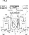
- the RF battery ⁇ includes a battery cell 100 in which a positive electrode cell 102 and a negative electrode cell 103 are separated from each other by a membrane 101 through which a hydrogen ion passes.
- the positive electrode cell 102 incorporates a positive electrode 104, and a positive electrolyte tank 106 that stores a positive electrolyte is connected to the positive electrode cell 102 via conduit pipes 108 and 110.
- the conduit pipe 108 is provided with a pump 112, and these members 106, 108, 110, and 112 constitute a positive electrolyte circulation mechanism 100P that circulates the positive electrolyte.
- the negative electrode cell 103 incorporates a negative electrode 105, and a negative electrolyte tank 107 that stores a negative electrolyte is connected to the negative electrode cell 103 via conduit pipes 109 and 111.
- the conduit pipe 109 is provided with a pump 113, and these members 107, 109, 111, and 113 constitute a negative electrolyte circulation mechanism 100N that circulates the negative electrolyte.
- the electrolytes stored in the respective tanks 106 and 107 are circulated inside the cells 102 and 103 by the pumps 112 and 113 during charging and discharging. When charging and discharging are not performed, the pumps 112 and 113 are stopped, and the electrolytes are not circulated.
- the aforementioned battery cell 100 is typically formed inside a structure body, which is called a cell stack 200, such as that shown in Fig. 2 .
- the cell stack 200 is constituted by a layered structure, which is called a substack 200s, the substack 200s being held from both sides thereof by two end plates 210 and 220 and being fastened by fastening mechanisms 230 (in the illustrated configuration, a plurality of the substacks 200s are used).
- the substack 200s has a configuration in which a layered body is held between supply/discharge plates 190 and 190 (refer to the lower illustration of Fig.
- the layered body including layers of stacked cell units that are each constituted by a cell frame 120, the positive electrode 104, the membrane 101, the negative electrode 105, and a cell frame 120.
- Each of the cell frames 120 included in the cell units includes a frame body 122 that has a through window and a bipolar plate 121 that closes the through window, the positive electrode 104 is arranged on one surface of the bipolar plate 121 so as to be in contact therewith, and the negative electrode 105 is arranged on the other surface of the bipolar plate 121 so as to be in contact therewith.
- the battery cell 100 is formed one each between the bipolar plates 121 of the cell frames 120 adjacent to each other.
- the circulation of the electrolyte to the battery cell 100 via the supply/discharge plates 190 and 190 is performed using liquid supply manifolds 123 and 124 and liquid discharge manifolds 125 and 126 that are formed in each frame body 122.
- the positive electrolyte is supplied from the liquid supply manifold 123 via an inlet slit formed on one surface side (front side of the figure) of each frame body 122 to the positive electrode 104 and is discharged via an outlet slit formed in an upper portion of each frame body 122 to the liquid discharge manifold 125.
- the negative electrolyte is supplied from the liquid supply manifold 124 via an inlet slit (indicated by broken lines) formed on the other surface side (rear side of the figure) of each frame body 122 to the negative electrode 105 and is discharged via an outlet slit (indicated by broken lines) formed in the upper portion of each frame body 122 to the liquid discharge manifold 126.
- a ring-shaped sealing member 127 such as an O-ring or a flat packing, is arranged between the cell frames 120 so that leakage of the electrolytes from the substacks 200s is suppressed.
- the RF battery transport structure 1 includes a cell stack 2, a container 3, and vibration absorbing members 4.
- the RF battery transport structure 1 includes a cell stack 2, a container 3, and vibration absorbing members 4.
- the container 3 in which the cell stack 2 is housed is transported.
- each constituent of the RF battery transport structure 1 will be described in detail.
- the basic configuration of the cell stack 2 shown in Figs. 3 and 4 is similar to that of the typical cell stack 200 described with reference to Fig. 2 .
- Members that have functions identical to those of the constituent members of the cell stack 200 are given reference signs identical to those of the constituent members of the cell stack 200, and detailed description thereof will be omitted.
- the cell stack 2 is formed, as shown in Fig. 2 , by a plurality of stacked layers of the substacks 200s that each include a plurality of stacked layers of the battery cells held between the supply/discharge plates 190.
- the plurality of substacks 200s are held between the pair of end plates 210 and 220 and fastened.
- the end plate 210 (220; refer to Fig. 4 ) of the present example includes, at a vertically lower end portion thereof, a pair of attachment portions 21 (22; refer to Fig. 4 ) extending in the width direction (left-right direction in Fig. 3 ) of the end plate 210 (220). That is, the cell stack 2 includes four of the attachment portions 21 and 22 in total.
- the vibration absorbing members 4, which will be described later, are attached to these attachment portions 21 and 22.
- each of the attachment portions 21 is constituted by two triangular plate portions 21A and 21B that have a right-angled triangle shape (refer to Fig. 3 ) and that are separated from each other in the thickness direction of the end plate 210; and a rectangular plate portion 21C that connects the lower ends of the two triangular plate portions 21A and 21B to each other.
- the triangular plate portion 21A is connected to one surface (surface on the right side of the figure) of the end plate 210 with no level difference
- the triangular plate portion 21B is connected to the other surface (surface on the left side of the figure) of the end plate 210 with no level difference.
- the rectangular plate portion 21C includes a bolt hole into which a bolt for fixing the vibration absorbing member 4, which will be described later, is to be inserted.
- the attachment portion 22 also has a configuration similar to that of the attachment portion 21.
- a container of an existing standard for example, 40-feet container for transport
- At least the cell stack 2, among the constituent members of the redox flow battery, is housed inside the container 3.
- the cell stack 2 may be directly placed, as shown, on a container bottom surface 30 of the container 3 or may be placed on a base of a certain type.
- a complete set of the constituent members of the redox flow battery is housed inside the container 3. Specifically, it is possible to enumerate a mode in which, in addition to the aforementioned cell stack 2, the circulation mechanisms 100P and 100N, which have been described with reference to Fig. 1 , a control mechanism that controls the circulation and the like of the electrolytes, and the like are housed inside the container 3. Note that it is suitable to separately transport the electrolytes without placing the electrolytes in the tanks 106 and 107.
- the vibration absorbing member 4 is a member that absorbs the vibration of the container 3 when the container 3 is subjected to vibration or when a shock is applied to the container 3.
- the vibration absorbing member 4 is provided one each on the attachment portions 21 and 22 provided on the end plates 210 and 220.
- an air spring is employed as the vibration absorbing member 4.
- the air spring 4 is capable of greatly attenuating large vibration and does not easily sympathetically vibrate, and the air spring 4 is thus capable of effectively suppressing the vibration of the cell stack 2 during transport.
- the air spring 4 has an advantage whereby it is possible to easily adjust the support height of the cell stack 2 by adjusting the amount of air packed in the air spring 4.
- the air spring 4 it is possible to enumerate, for example, the Sumimount (trade name) of Sumitomo Electric Industries, Ltd.
- an oil dumper or the like is usable.
- the air spring 4 includes an upper piece portion 40, a lower piece portion 41, and an elastic portion 42.
- the upper piece portion 40 is a member that is to be fixed to the attachment portion 21 (22) and that has high rigidity.
- the lower piece portion 41 is a member that serves as a base in contact with a placement surface (the container bottom surface 30 in the present example) on which the cell stack 2 is placed.
- the elastic portion 42 is a member that is disposed between the upper piece portion 40 and the lower piece portion 41 and that is constituted by an elastic body of rubber or the like, and air is packed inside the elastic portion 42. It is acceptable that a plurality of stages of the elastic portions 42 are stacked.
- the RF battery transport structure 1 having the aforementioned configuration, it is possible to suppress the vibration of the cell stack 2 by the vibration absorbing members 4 that vertically support the cell stack 2 from below. Therefore, the cell stack 2 is suppressed from being applied with a large inertial force, for example, even when the container 3 is subjected to vibration or even when a shock is applied to the container 3. As a result, it is possible to suppress the cell stack 2 from being damaged during transport, and it is possible to smoothly install and operate the redox flow battery after transport.
- the cell stack 2 is fixed to an installation surface via an insulator such as an epoxy. Therefore, the air springs 4 that have been attached to the attachment portions 21 and 22 during transport are replaced with insulators.
- the air springs 4 include the elastic portions 42, which have insulating properties; thus, if the elastic portions 42 have predetermined insulation performance, there is a possibility that the air springs 4 are usable as alternatives to the insulators. In this case, it is possible to reduce labor for replacing the air springs 4 with insulators.
- an acceleration sensor was attached to an upper-end center portion of the end plate 210 shown in Figs. 3 and 4 , and the inertial force in the vertical direction applied to the cell stack 2 during load and discharge of the container 3 was measured.
- the inertial force applied to the cell stack 2 was found to be 3 G or less.
- the air springs 4 of the cell stack 2 in Figs. 3 and 4 were replaced with rigid support bases and the inertial force in the aforementioned vertical direction was measured, the inertial force was as high as approximately 10 G.
- each of the end plate 210 and the other end plate 220 (refer to Fig. 2 ), which is hidden on the deeper side of the figure, is provided with four of the damping rubbers 4.
- the damping rubbers 4 are provided so as to be spaced from each other with a substantially identical gap therebetween in the left-right direction of the figure.
- the number of the damping rubbers 4 is not particularly limited.
- the damping rubbers 4 may be a natural rubber or may be a synthetic rubber.
- a chloroprene rubber (polychloroprene), an ethylene propylene rubber and the like are suitably usable.
- the damping rubbers 4 are capable of maintaining its vibration absorption ability for a long period and are thus desirable as the vibration absorbing members during transport.
- the damping rubbers 4 is capable of absorbing the vibration during transport, with certainty for a long period, when sea transport and long-haul land transport are performed.
Landscapes
- Engineering & Computer Science (AREA)
- Chemical Kinetics & Catalysis (AREA)
- General Chemical & Material Sciences (AREA)
- Sustainable Development (AREA)
- Sustainable Energy (AREA)
- Chemical & Material Sciences (AREA)
- Life Sciences & Earth Sciences (AREA)
- Electrochemistry (AREA)
- Manufacturing & Machinery (AREA)
- Mechanical Engineering (AREA)
- General Engineering & Computer Science (AREA)
- Fuel Cell (AREA)
- Physics & Mathematics (AREA)
- Acoustics & Sound (AREA)
- Aviation & Aerospace Engineering (AREA)
Abstract
Description
- The present invention relates to a redox flow battery transport structure, a redox flow battery transport method, and a redox flow battery.
- The present application claims priority based on Japanese Application No.
2016-084541, filed April 20, 2016 - One of large capacity storage batteries that store new energy of solar photovoltaic power generation or wind power generation is an electrolyte-circulation battery, typically a redox flow battery. The redox flow battery is a battery that utilizes a difference in an oxidation-reduction potential between an ion contained in a positive electrolyte and an ion contained in a negative electrolyte to perform charging and discharging (refer, for example, to PTL 1).
- PTL 1: Japanese Unexamined Patent Application Publication No.
2015-79738 - A redox flow battery transport structure according to the present disclosure includes:
- a cell stack that includes a plurality of stacked layers of battery cells of a redox flow battery;
- a container in which the cell stack is housed; and
- a vibration absorbing member that vertically supports the cell stack from below in the container.
- A redox flow battery transport method according to the present disclosure includes:
housing a cell stack that is vertically supported from below by a vibration absorbing member in a container, the cell stack including a plurality of stacked layers of battery cells of a redox flow battery; and transporting the container. - A redox flow battery according to the present disclosure includes:
- a cell stack that includes a plurality of stacked layers of battery cells of a redox flow battery; and
- a vibration absorbing member that vertically supports the cell stack from below. Brief Description of Drawings
-
- [
Fig. 1] Figure 1 is an illustration of an operational principle of a redox flow battery. - [
Fig. 2] Figure 2 is a schematic illustration of a configuration of a cell stack. - [
Fig. 3] Figure 3 is a schematic partial sectional view of a redox flow battery transport structure according to a first embodiment. - [
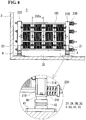
Fig. 4] Figure 4 is a schematic partial sectional view of the redox flow battery transport structure viewed from the left side surface inFig. 3 . - [
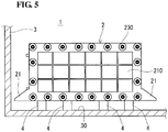
Fig. 5] Figure 5 is a schematic partial sectional view of a redox flow battery transport structure according to a second embodiment. - In recent years, an increased demand for redox flow batteries as storage means for new energy is expected. For example, constructing a solar photovoltaic power plant in an extensive non-residential area, such as a desert, and installing a redox flow battery therein are under consideration. Here, it is assumed that constituent members of the redox flow battery are transported by sea or transported by land on unpaved land, and there is a concern that the aforementioned constituent members may be damaged during transport under such severe transport conditions. However, a redox flow battery transport structure that is optimal under severe transport conditions has currently not been examined.
- The present disclosure provides a redox flow battery transport structure, a redox flow battery transport method, and a redox flow battery which are capable of suppressing the redox flow battery from being damaged during transport even under severe transport conditions.
- According to the aforementioned redox flow battery transport structure, it is possible to suppress a cell stack included in a redox flow battery from being damaged due to the vibration during transport.
- According to the aforementioned redox flow battery transport method, it is possible to transport a cell stack of a redox flow battery while suppressing the cell stack included in the redox flow battery from being damaged.
- According to the aforementioned redox flow battery, it is possible to suppress a cell stack from being damaged due to the vibration during transport.
- First, contents of an embodiment of the invention of the present application will be enumerated and described.
- As measures for a case in which constituent members of a redox flow battery are housed in a container and transported, a measure of attaching a vibration control structure to a lower portion of the container is enumerated. In the measure, however, it is not possible to buffer stress that is applied to the constituent members of the redox flow battery present inside the container when transshipment and the like of the container is performed. However, attaching vibration control structures to all of the constituent members is not realistic in terms of labor and cost. Accordingly, the inventors of the present invention examined which of the constituent members of the redox flow battery the vibration control structure should be employed for when the redox flow battery is housed in a container and transported. As a result, the inventors of the present invention found that the vibration control structure is needed to be employed for a cell stack in which membranes, electrodes, and the like having comparatively low strength are stacked. On the basis of the finding, a redox flow battery transport structure according to an embodiment will be specified below.
- <1> A redox flow battery transport structure according to an embodiment includes
- a cell stack that includes a plurality of stacked layers of battery cells of a redox flow battery,
- a container in which the cell stack is housed, and
- a vibration absorbing member that vertically supports the cell stack from below in the container.
- Employing a member that vertically supports the cell stack from below as the vibration absorbing member makes it possible to suppress, even when the container is subjected to vibration or even when a shock is applied to the container, a large inertial force applied to the cell stack of the redox flow battery. As a result, it is possible to suppress the cell stack from being damaged during transport, and it is possible to smoothly install and operate the redox flow battery after transport.
- <2> One aspect of the redox flow battery transport structure according to the embodiment is an aspect
in which the vibration absorbing member is a damping rubber. - The damping rubber is capable of maintaining its vibration absorption ability for a long period and is thus desirable as the vibration absorbing member during transport. In particular, the damping rubber is capable of absorbing the vibration during transport, with certainty for a long period, when sea transport and long-haul land transport are performed.
- <3> One aspect of the redox flow battery transport structure according to the embodiment is an aspect
in which the vibration absorbing member is an air spring. - The air spring is capable of greatly attenuating large vibration and does not easily sympathetically vibrate, and the air spring is thus desirable as the vibration absorbing member during transport. In addition, the air spring has an advantage whereby it is possible to easily adjust the support height of the cell stack by adjusting the amount of air packed in the air spring.
- <4> One aspect of the redox flow battery transport structure according to the embodiment is an aspect
- in which the cell stack includes a pair of end plates that hold and fasten a layered structure from both sides thereof, the layered structure including the plurality of stacked layers of battery cells, and
- in which each of the end plates includes, at a vertically lower portion thereof, an attachment portion to which the vibration absorbing member is attached.
- The pair of end plates are for fastening a layered structure body including stacked layers of battery cells from both sides thereof to maintain the layered state of the layered structure body and thus have high strength and high rigidity. Therefore, the end plates are suitable for use as members on which an attachment portion of a vibration absorbing member that supports a heavy cell stack and that absorbs vibration is provided.
- <5> A redox flow battery transport method according to the embodiment includes
housing a cell stack that is vertically supported from below by a vibration absorbing member in a container, the cell stack including a plurality of stacked layers of battery cells of a redox flow battery; and transporting the container. - Vertically supporting the cell stack from below by the vibration absorbing member makes it possible to suppress, even when the container is subjected to vibration or even when a shock is applied to the container, a large inertial force applied to the cell stack of the redox flow battery. As a result, it is possible to suppress the cell stack from being damaged during transport, and it is possible to smoothly install and operate the redox flow battery after transport.
- <6> A redox flow battery according to the embodiment includes
- a cell stack that includes a plurality of stacked layers of battery cells of a redox flow battery, and
- a vibration absorbing member that vertically supports the cell stack from below.
- Vertically supporting the cell stack from below by the vibration absorbing member makes it possible to suppress the cell stack of the redox flow battery from being damaged due to the vibration during the transport of the redox flow battery.
- Hereinafter, embodiments of the transport structure and the transport method for the redox flow battery (RF battery) according to embodiments will be described. Note that the present invention is not limited to the configuration indicated in the embodiments; the present invention is indicated by the claims and intends to include all modifications within the meaning and scope equivalent to the claims.
- Prior to describing a RF
battery transport structure 1 and a transport method according to the embodiment, a basic configuration of a RF battery α will be described on the basis ofFigs. 1 and2 . - As shown in the illustration of the operational principle of the RF battery α in
Fig. 1 , the RF battery α includes abattery cell 100 in which apositive electrode cell 102 and anegative electrode cell 103 are separated from each other by amembrane 101 through which a hydrogen ion passes. Thepositive electrode cell 102 incorporates apositive electrode 104, and apositive electrolyte tank 106 that stores a positive electrolyte is connected to thepositive electrode cell 102 viaconduit pipes conduit pipe 108 is provided with apump 112, and thesemembers electrolyte circulation mechanism 100P that circulates the positive electrolyte. Similarly, thenegative electrode cell 103 incorporates anegative electrode 105, and anegative electrolyte tank 107 that stores a negative electrolyte is connected to thenegative electrode cell 103 viaconduit pipes conduit pipe 109 is provided with apump 113, and thesemembers electrolyte circulation mechanism 100N that circulates the negative electrolyte. The electrolytes stored in therespective tanks cells pumps pumps - The
aforementioned battery cell 100 is typically formed inside a structure body, which is called acell stack 200, such as that shown inFig. 2 . Thecell stack 200 is constituted by a layered structure, which is called asubstack 200s, thesubstack 200s being held from both sides thereof by twoend plates substacks 200s are used). As shown in the upper illustration ofFig. 2 , thesubstack 200s has a configuration in which a layered body is held between supply/discharge plates 190 and 190 (refer to the lower illustration ofFig. 2 ), the layered body including layers of stacked cell units that are each constituted by acell frame 120, thepositive electrode 104, themembrane 101, thenegative electrode 105, and acell frame 120. Each of the cell frames 120 included in the cell units includes aframe body 122 that has a through window and abipolar plate 121 that closes the through window, thepositive electrode 104 is arranged on one surface of thebipolar plate 121 so as to be in contact therewith, and thenegative electrode 105 is arranged on the other surface of thebipolar plate 121 so as to be in contact therewith. In this configuration, thebattery cell 100 is formed one each between thebipolar plates 121 of the cell frames 120 adjacent to each other. - The circulation of the electrolyte to the
battery cell 100 via the supply/discharge plates liquid supply manifolds liquid discharge manifolds frame body 122. The positive electrolyte is supplied from theliquid supply manifold 123 via an inlet slit formed on one surface side (front side of the figure) of eachframe body 122 to thepositive electrode 104 and is discharged via an outlet slit formed in an upper portion of eachframe body 122 to theliquid discharge manifold 125. Similarly, the negative electrolyte is supplied from theliquid supply manifold 124 via an inlet slit (indicated by broken lines) formed on the other surface side (rear side of the figure) of eachframe body 122 to thenegative electrode 105 and is discharged via an outlet slit (indicated by broken lines) formed in the upper portion of eachframe body 122 to theliquid discharge manifold 126. A ring-shapedsealing member 127, such as an O-ring or a flat packing, is arranged between the cell frames 120 so that leakage of the electrolytes from thesubstacks 200s is suppressed. - Next, the RF
battery transport structure 1 according to the embodiment will be described on the basis ofFigs. 3 and4 . The RFbattery transport structure 1 includes acell stack 2, acontainer 3, andvibration absorbing members 4. When thecell stack 2 of the RF battery is transported, thecontainer 3 in which thecell stack 2 is housed is transported. Hereinafter, each constituent of the RFbattery transport structure 1 will be described in detail. - The basic configuration of the
cell stack 2 shown inFigs. 3 and4 is similar to that of thetypical cell stack 200 described with reference toFig. 2 . Members that have functions identical to those of the constituent members of thecell stack 200 are given reference signs identical to those of the constituent members of thecell stack 200, and detailed description thereof will be omitted. - As described above, the
cell stack 2 is formed, as shown inFig. 2 , by a plurality of stacked layers of thesubstacks 200s that each include a plurality of stacked layers of the battery cells held between the supply/discharge plates 190. The plurality ofsubstacks 200s are held between the pair ofend plates - The end plate 210 (220; refer to
Fig. 4 ) of the present example includes, at a vertically lower end portion thereof, a pair of attachment portions 21 (22; refer toFig. 4 ) extending in the width direction (left-right direction inFig. 3 ) of the end plate 210 (220). That is, thecell stack 2 includes four of theattachment portions vibration absorbing members 4, which will be described later, are attached to theseattachment portions - As shown in the circled enlarged view in
Fig. 4 , each of theattachment portions 21 is constituted by twotriangular plate portions Fig. 3 ) and that are separated from each other in the thickness direction of theend plate 210; and arectangular plate portion 21C that connects the lower ends of the twotriangular plate portions triangular plate portion 21A is connected to one surface (surface on the right side of the figure) of theend plate 210 with no level difference, and thetriangular plate portion 21B is connected to the other surface (surface on the left side of the figure) of theend plate 210 with no level difference. In addition, therectangular plate portion 21C includes a bolt hole into which a bolt for fixing thevibration absorbing member 4, which will be described later, is to be inserted. Note that theattachment portion 22 also has a configuration similar to that of theattachment portion 21. - As the
container 3, a container of an existing standard (for example, 40-feet container for transport) is usable. At least thecell stack 2, among the constituent members of the redox flow battery, is housed inside thecontainer 3. Thecell stack 2 may be directly placed, as shown, on acontainer bottom surface 30 of thecontainer 3 or may be placed on a base of a certain type. - It is acceptable that a complete set of the constituent members of the redox flow battery is housed inside the
container 3. Specifically, it is possible to enumerate a mode in which, in addition to theaforementioned cell stack 2, thecirculation mechanisms Fig. 1 , a control mechanism that controls the circulation and the like of the electrolytes, and the like are housed inside thecontainer 3. Note that it is suitable to separately transport the electrolytes without placing the electrolytes in thetanks - The
vibration absorbing member 4 is a member that absorbs the vibration of thecontainer 3 when thecontainer 3 is subjected to vibration or when a shock is applied to thecontainer 3. Thevibration absorbing member 4 is provided one each on theattachment portions end plates - In the present example, an air spring is employed as the
vibration absorbing member 4. Theair spring 4 is capable of greatly attenuating large vibration and does not easily sympathetically vibrate, and theair spring 4 is thus capable of effectively suppressing the vibration of thecell stack 2 during transport. In addition, theair spring 4 has an advantage whereby it is possible to easily adjust the support height of thecell stack 2 by adjusting the amount of air packed in theair spring 4. As theair spring 4, it is possible to enumerate, for example, the Sumimount (trade name) of Sumitomo Electric Industries, Ltd. As an alternative to theair spring 4, an oil dumper or the like is usable. - As shown in the circled enlarged views in
Figs. 3 and4 , theair spring 4 includes anupper piece portion 40, alower piece portion 41, and anelastic portion 42. Theupper piece portion 40 is a member that is to be fixed to the attachment portion 21 (22) and that has high rigidity. Thelower piece portion 41 is a member that serves as a base in contact with a placement surface (thecontainer bottom surface 30 in the present example) on which thecell stack 2 is placed. Theelastic portion 42 is a member that is disposed between theupper piece portion 40 and thelower piece portion 41 and that is constituted by an elastic body of rubber or the like, and air is packed inside theelastic portion 42. It is acceptable that a plurality of stages of theelastic portions 42 are stacked. - In the RF
battery transport structure 1 having the aforementioned configuration, it is possible to suppress the vibration of thecell stack 2 by thevibration absorbing members 4 that vertically support thecell stack 2 from below. Therefore, thecell stack 2 is suppressed from being applied with a large inertial force, for example, even when thecontainer 3 is subjected to vibration or even when a shock is applied to thecontainer 3. As a result, it is possible to suppress thecell stack 2 from being damaged during transport, and it is possible to smoothly install and operate the redox flow battery after transport. - At an installation place of the RF battery, the
cell stack 2 is fixed to an installation surface via an insulator such as an epoxy. Therefore, the air springs 4 that have been attached to theattachment portions elastic portions 42, which have insulating properties; thus, if theelastic portions 42 have predetermined insulation performance, there is a possibility that the air springs 4 are usable as alternatives to the insulators. In this case, it is possible to reduce labor for replacing the air springs 4 with insulators. - In an experimental example, an acceleration sensor was attached to an upper-end center portion of the
end plate 210 shown inFigs. 3 and4 , and the inertial force in the vertical direction applied to thecell stack 2 during load and discharge of thecontainer 3 was measured. As a result, the inertial force applied to thecell stack 2 was found to be 3 G or less. In contrast, when the air springs 4 of thecell stack 2 inFigs. 3 and4 were replaced with rigid support bases and the inertial force in the aforementioned vertical direction was measured, the inertial force was as high as approximately 10 G. These results clearly indicate that the air springs is capable of greatly reducing the inertial force applied to thecell stack 2 during transport. - In a second embodiment, an example in which damping rubbers are used as the
vibration absorbing members 4 will be described on the basis ofFig. 5 . - In the RF battery transport structure of the present example shown in
Fig. 5 , each of theend plate 210 and the other end plate 220 (refer toFig. 2 ), which is hidden on the deeper side of the figure, is provided with four of the dampingrubbers 4. Preferably, the dampingrubbers 4 are provided so as to be spaced from each other with a substantially identical gap therebetween in the left-right direction of the figure. The number of the dampingrubbers 4 is not particularly limited. In addition, the dampingrubbers 4 may be a natural rubber or may be a synthetic rubber. As the synthetic rubber, a chloroprene rubber (polychloroprene), an ethylene propylene rubber and the like are suitably usable. - The damping
rubbers 4 are capable of maintaining its vibration absorption ability for a long period and are thus desirable as the vibration absorbing members during transport. In particular, the dampingrubbers 4 is capable of absorbing the vibration during transport, with certainty for a long period, when sea transport and long-haul land transport are performed. -
- 1 redox flow battery transport structure (RF battery transport structure)
- 2 cell stack
- 21,22
attachment portion triangular plate portion 21C rectangular plate portion
- 21,22
- 3 container
- 30 container bottom surface
- 4 vibration absorbing member (air spring or damping rubber)
- 40
upper piece portion 41lower piece portion 42 elastic portion
- 40
- 2 cell stack
- α redox flow battery (RF battery)
- 100
battery cell 101membrane 102positive electrode cell 103 negative electrode cell- 100P positive
electrolyte circulation mechanism 100N negative electrolyte circulation mechanism - 104
positive electrode 105negative electrode 106 positive electrolyte tank - 107
negative electrolyte tank - 112, 113 pump
- 120
cell frame 121bipolar plate 122 frame body - 123, 124 liquid supply manifold
- 125, 126 liquid discharge manifold
- 127 sealing member
- 190 supply/
discharge plate
- 100P positive
- 200
cell stack 200s substack- 230 fastening mechanism
Claims (6)
- A redox flow battery transport structure comprising:a cell stack that includes a plurality of stacked layers of battery cells of a redox flow battery;a container in which the cell stack is housed; anda vibration absorbing member that vertically supports the cell stack from below in the container.
- The redox flow battery transport structure according to Claim 1, wherein the vibration absorbing member is a damping rubber.
- The redox flow battery transport structure according to Claim 1, wherein the vibration absorbing member is an air spring.
- The redox flow battery transport structure according to any one of Claims 1 to 3,
wherein the cell stack includes a pair of end plates that hold and fasten a layered structure from both ends thereof, the layered structure including the plurality of stacked layers of battery cells, and
wherein each of the end plates includes, at a vertically lower portion thereof, an attachment portion to which the vibration absorbing member is attached. - A redox flow battery transport method comprising: housing a cell stack that is vertically supported from below by a vibration absorbing member in a container, the cell stack including a plurality of stacked layers of battery cells of a redox flow battery; and transporting the container.
- A redox flow battery comprising:a cell stack that includes a plurality of stacked layers of battery cells of a redox flow battery; anda vibration absorbing member that vertically supports the cell stack from below.
Applications Claiming Priority (2)
| Application Number | Priority Date | Filing Date | Title |
|---|---|---|---|
| JP2016084541 | 2016-04-20 | ||
| PCT/JP2017/015633 WO2017183643A1 (en) | 2016-04-20 | 2017-04-18 | Redox flow battery transport structure, redox flow battery transport method, and redox flow battery |
Publications (2)
| Publication Number | Publication Date |
|---|---|
| EP3447835A1 true EP3447835A1 (en) | 2019-02-27 |
| EP3447835A4 EP3447835A4 (en) | 2019-05-08 |
Family
ID=60116826
Family Applications (1)
| Application Number | Title | Priority Date | Filing Date |
|---|---|---|---|
| EP17785981.6A Withdrawn EP3447835A4 (en) | 2016-04-20 | 2017-04-18 | REDOX BATTERY TRANSPORT STRUCTURE, REDOX BATTERY TRANSPORT METHOD AND REDOX BATTERY |
Country Status (7)
| Country | Link |
|---|---|
| US (1) | US20190097251A1 (en) |
| EP (1) | EP3447835A4 (en) |
| JP (1) | JPWO2017183643A1 (en) |
| KR (1) | KR20180137493A (en) |
| CN (1) | CN109071107A (en) |
| AU (1) | AU2017253304A1 (en) |
| WO (1) | WO2017183643A1 (en) |
Families Citing this family (3)
| Publication number | Priority date | Publication date | Assignee | Title |
|---|---|---|---|---|
| CN108550748A (en) * | 2018-06-05 | 2018-09-18 | 安徽艾伊德动力科技有限公司 | A kind of novel power battery echelon utilizes preceding stacking structure |
| US11462764B2 (en) * | 2020-05-15 | 2022-10-04 | Ess Tech, Inc. | Double-stack redox flow battery |
| KR20220078148A (en) * | 2020-12-03 | 2022-06-10 | 현대자동차주식회사 | Fuel cell mounting system |
Family Cites Families (13)
| Publication number | Priority date | Publication date | Assignee | Title |
|---|---|---|---|---|
| US4877136A (en) * | 1987-04-17 | 1989-10-31 | Bridgestone Corporation | Vibration free container for transportation |
| JP3040401B2 (en) * | 1989-03-03 | 2000-05-15 | 株式会社ブリヂストン | Automatic vibration isolator for transportation |
| JPH092278A (en) * | 1995-06-19 | 1997-01-07 | Kobayashi Hansou Kiki:Kk | Conveyor support device |
| JP2000067899A (en) * | 1998-08-20 | 2000-03-03 | Sumitomo Electric Ind Ltd | Redox flow type secondary battery cell stack |
| JP3682244B2 (en) * | 2001-06-12 | 2005-08-10 | 住友電気工業株式会社 | Cell frame for redox flow battery and redox flow battery |
| JP2007188773A (en) * | 2006-01-13 | 2007-07-26 | Honda Motor Co Ltd | Fuel cell stack |
| US20130011704A1 (en) * | 2008-07-07 | 2013-01-10 | Enervault Corporation | Redox Flow Battery System with Multiple Independent Stacks |
| CN102148412A (en) * | 2010-02-09 | 2011-08-10 | 中大工业集团公司 | Automatic control cooling device of battery pack of electric passenger vehicle |
| CN202827264U (en) * | 2012-08-22 | 2013-03-27 | 国网电力科学研究院武汉南瑞有限责任公司 | Electricity energy stored vehicle based on vanadium battery |
| JP6008202B2 (en) * | 2013-05-29 | 2016-10-19 | トヨタ自動車株式会社 | Fuel cell stack |
| JP6098998B2 (en) * | 2013-09-12 | 2017-03-22 | 住友電気工業株式会社 | Battery cell stack and redox flow battery |
| JP6066887B2 (en) * | 2013-11-13 | 2017-01-25 | 三菱日立パワーシステムズ株式会社 | Fuel cell transport device |
| CN103779586B (en) * | 2014-01-13 | 2016-01-20 | 江苏绿遥燃料电池系统制造有限公司 | A kind of fuel cell end plate |
-
2017
- 2017-04-18 US US16/094,928 patent/US20190097251A1/en not_active Abandoned
- 2017-04-18 WO PCT/JP2017/015633 patent/WO2017183643A1/en not_active Ceased
- 2017-04-18 EP EP17785981.6A patent/EP3447835A4/en not_active Withdrawn
- 2017-04-18 JP JP2018513190A patent/JPWO2017183643A1/en active Pending
- 2017-04-18 AU AU2017253304A patent/AU2017253304A1/en not_active Abandoned
- 2017-04-18 KR KR1020187030146A patent/KR20180137493A/en not_active Withdrawn
- 2017-04-18 CN CN201780024661.XA patent/CN109071107A/en active Pending
Also Published As
| Publication number | Publication date |
|---|---|
| KR20180137493A (en) | 2018-12-27 |
| WO2017183643A1 (en) | 2017-10-26 |
| CN109071107A (en) | 2018-12-21 |
| JPWO2017183643A1 (en) | 2019-02-28 |
| AU2017253304A1 (en) | 2018-10-25 |
| US20190097251A1 (en) | 2019-03-28 |
| EP3447835A4 (en) | 2019-05-08 |
Similar Documents
| Publication | Publication Date | Title |
|---|---|---|
| US11509014B2 (en) | Battery rack and power storage apparatus including the same | |
| US9371009B2 (en) | Mount structure for fuel cell stack | |
| JP6220849B2 (en) | Large electrochemical energy storage housing and module | |
| US9711819B2 (en) | Mount structure for fuel cell stack | |
| US10230123B2 (en) | Battery cell and redox flow battery | |
| US20130164592A1 (en) | Method and Apparatus for Manufacturing a Battery for a Vehicle | |
| US20160344058A1 (en) | Fuel cell stack and mount structure therefor | |
| US20120308864A1 (en) | Cell block with lateral supporting of the cells | |
| US12183936B2 (en) | Battery pack and vehicle comprising same battery pack | |
| AU2021346597A1 (en) | Battery rack, energy storage system, and power generation system | |
| US20190097251A1 (en) | Redox flow battery transport structure, redox flow battery transport method, and redox flow battery | |
| US10224563B2 (en) | Frame body, cell frame, cell stack, and redox flow battery | |
| AU2021347786A1 (en) | Battery rack, energy storage system, and power generation system | |
| EP2899789A1 (en) | Redox flow battery | |
| US20090226794A1 (en) | Fuel cell stack clamping device | |
| US20190267590A1 (en) | Battery pack fixing apparatus | |
| JPWO2019102544A1 (en) | Redox flow battery | |
| KR102022641B1 (en) | Battery pack and vehicle comprising the battery pack | |
| CN108140752A (en) | Electrode stack attaching means | |
| CN110036517A (en) | redox flow battery | |
| US20200112044A2 (en) | Cell frame and redox flow battery | |
| CN100441438C (en) | Support structure for power system | |
| WO2017169463A1 (en) | Redox flow battery frame body, redox flow battery, and cell stack | |
| JP2018041684A (en) | Power generation inspection device for fuel cell stack | |
| KR20240023825A (en) | Battery rack and energy storage system including the same |
Legal Events
| Date | Code | Title | Description |
|---|---|---|---|
| STAA | Information on the status of an ep patent application or granted ep patent |
Free format text: STATUS: THE INTERNATIONAL PUBLICATION HAS BEEN MADE |
|
| PUAI | Public reference made under article 153(3) epc to a published international application that has entered the european phase |
Free format text: ORIGINAL CODE: 0009012 |
|
| STAA | Information on the status of an ep patent application or granted ep patent |
Free format text: STATUS: REQUEST FOR EXAMINATION WAS MADE |
|
| 17P | Request for examination filed |
Effective date: 20181003 |
|
| AK | Designated contracting states |
Kind code of ref document: A1 Designated state(s): AL AT BE BG CH CY CZ DE DK EE ES FI FR GB GR HR HU IE IS IT LI LT LU LV MC MK MT NL NO PL PT RO RS SE SI SK SM TR |
|
| AX | Request for extension of the european patent |
Extension state: BA ME |
|
| A4 | Supplementary search report drawn up and despatched |
Effective date: 20190410 |
|
| RIC1 | Information provided on ipc code assigned before grant |
Ipc: B65D 90/12 20060101ALI20190404BHEP Ipc: H01M 8/18 20060101AFI20190404BHEP Ipc: H01M 8/24 20160101ALI20190404BHEP |
|
| DAV | Request for validation of the european patent (deleted) | ||
| DAX | Request for extension of the european patent (deleted) | ||
| STAA | Information on the status of an ep patent application or granted ep patent |
Free format text: STATUS: THE APPLICATION IS DEEMED TO BE WITHDRAWN |
|
| 18D | Application deemed to be withdrawn |
Effective date: 20191112 |