EP3447381B1 - Kühlpfadstruktur zur konzentrierten kühlung eines dichtungsbereichs und gasturbinenbrennkammer damit - Google Patents
Kühlpfadstruktur zur konzentrierten kühlung eines dichtungsbereichs und gasturbinenbrennkammer damit Download PDFInfo
- Publication number
- EP3447381B1 EP3447381B1 EP18181893.1A EP18181893A EP3447381B1 EP 3447381 B1 EP3447381 B1 EP 3447381B1 EP 18181893 A EP18181893 A EP 18181893A EP 3447381 B1 EP3447381 B1 EP 3447381B1
- Authority
- EP
- European Patent Office
- Prior art keywords
- cooling
- seal area
- path structure
- guide plate
- central axis
- Prior art date
- Legal status (The legal status is an assumption and is not a legal conclusion. Google has not performed a legal analysis and makes no representation as to the accuracy of the status listed.)
- Active
Links
Images




Classifications
-
- F—MECHANICAL ENGINEERING; LIGHTING; HEATING; WEAPONS; BLASTING
- F01—MACHINES OR ENGINES IN GENERAL; ENGINE PLANTS IN GENERAL; STEAM ENGINES
- F01D—NON-POSITIVE DISPLACEMENT MACHINES OR ENGINES, e.g. STEAM TURBINES
- F01D9/00—Stators
- F01D9/02—Nozzles; Nozzle boxes; Stator blades; Guide conduits, e.g. individual nozzles
- F01D9/023—Transition ducts between combustor cans and first stage of the turbine in gas-turbine engines; their cooling or sealings
-
- F—MECHANICAL ENGINEERING; LIGHTING; HEATING; WEAPONS; BLASTING
- F23—COMBUSTION APPARATUS; COMBUSTION PROCESSES
- F23R—GENERATING COMBUSTION PRODUCTS OF HIGH PRESSURE OR HIGH VELOCITY, e.g. GAS-TURBINE COMBUSTION CHAMBERS
- F23R3/00—Continuous combustion chambers using liquid or gaseous fuel
- F23R3/002—Wall structures
-
- F—MECHANICAL ENGINEERING; LIGHTING; HEATING; WEAPONS; BLASTING
- F02—COMBUSTION ENGINES; HOT-GAS OR COMBUSTION-PRODUCT ENGINE PLANTS
- F02C—GAS-TURBINE PLANTS; AIR INTAKES FOR JET-PROPULSION PLANTS; CONTROLLING FUEL SUPPLY IN AIR-BREATHING JET-PROPULSION PLANTS
- F02C7/00—Features, components parts, details or accessories, not provided for in, or of interest apart form groups F02C1/00 - F02C6/00; Air intakes for jet-propulsion plants
- F02C7/12—Cooling of plants
-
- F—MECHANICAL ENGINEERING; LIGHTING; HEATING; WEAPONS; BLASTING
- F01—MACHINES OR ENGINES IN GENERAL; ENGINE PLANTS IN GENERAL; STEAM ENGINES
- F01D—NON-POSITIVE DISPLACEMENT MACHINES OR ENGINES, e.g. STEAM TURBINES
- F01D25/00—Component parts, details, or accessories, not provided for in, or of interest apart from, other groups
- F01D25/08—Cooling; Heating; Heat-insulation
- F01D25/12—Cooling
-
- F—MECHANICAL ENGINEERING; LIGHTING; HEATING; WEAPONS; BLASTING
- F02—COMBUSTION ENGINES; HOT-GAS OR COMBUSTION-PRODUCT ENGINE PLANTS
- F02C—GAS-TURBINE PLANTS; AIR INTAKES FOR JET-PROPULSION PLANTS; CONTROLLING FUEL SUPPLY IN AIR-BREATHING JET-PROPULSION PLANTS
- F02C7/00—Features, components parts, details or accessories, not provided for in, or of interest apart form groups F02C1/00 - F02C6/00; Air intakes for jet-propulsion plants
- F02C7/28—Arrangement of seals
-
- F—MECHANICAL ENGINEERING; LIGHTING; HEATING; WEAPONS; BLASTING
- F16—ENGINEERING ELEMENTS AND UNITS; GENERAL MEASURES FOR PRODUCING AND MAINTAINING EFFECTIVE FUNCTIONING OF MACHINES OR INSTALLATIONS; THERMAL INSULATION IN GENERAL
- F16J—PISTONS; CYLINDERS; SEALINGS
- F16J15/00—Sealings
- F16J15/02—Sealings between relatively-stationary surfaces
- F16J15/021—Sealings between relatively-stationary surfaces with elastic packing
- F16J15/022—Sealings between relatively-stationary surfaces with elastic packing characterised by structure or material
-
- F—MECHANICAL ENGINEERING; LIGHTING; HEATING; WEAPONS; BLASTING
- F23—COMBUSTION APPARATUS; COMBUSTION PROCESSES
- F23M—CASINGS, LININGS, WALLS OR DOORS SPECIALLY ADAPTED FOR COMBUSTION CHAMBERS, e.g. FIREBRIDGES; DEVICES FOR DEFLECTING AIR, FLAMES OR COMBUSTION PRODUCTS IN COMBUSTION CHAMBERS; SAFETY ARRANGEMENTS SPECIALLY ADAPTED FOR COMBUSTION APPARATUS; DETAILS OF COMBUSTION CHAMBERS, NOT OTHERWISE PROVIDED FOR
- F23M5/00—Casings; Linings; Walls
- F23M5/08—Cooling thereof; Tube walls
- F23M5/085—Cooling thereof; Tube walls using air or other gas as the cooling medium
-
- F—MECHANICAL ENGINEERING; LIGHTING; HEATING; WEAPONS; BLASTING
- F23—COMBUSTION APPARATUS; COMBUSTION PROCESSES
- F23R—GENERATING COMBUSTION PRODUCTS OF HIGH PRESSURE OR HIGH VELOCITY, e.g. GAS-TURBINE COMBUSTION CHAMBERS
- F23R3/00—Continuous combustion chambers using liquid or gaseous fuel
- F23R3/02—Continuous combustion chambers using liquid or gaseous fuel characterised by the air-flow or gas-flow configuration
- F23R3/04—Air inlet arrangements
- F23R3/045—Air inlet arrangements using pipes
-
- F—MECHANICAL ENGINEERING; LIGHTING; HEATING; WEAPONS; BLASTING
- F05—INDEXING SCHEMES RELATING TO ENGINES OR PUMPS IN VARIOUS SUBCLASSES OF CLASSES F01-F04
- F05D—INDEXING SCHEME FOR ASPECTS RELATING TO NON-POSITIVE-DISPLACEMENT MACHINES OR ENGINES, GAS-TURBINES OR JET-PROPULSION PLANTS
- F05D2240/00—Components
- F05D2240/35—Combustors or associated equipment
-
- F—MECHANICAL ENGINEERING; LIGHTING; HEATING; WEAPONS; BLASTING
- F05—INDEXING SCHEMES RELATING TO ENGINES OR PUMPS IN VARIOUS SUBCLASSES OF CLASSES F01-F04
- F05D—INDEXING SCHEME FOR ASPECTS RELATING TO NON-POSITIVE-DISPLACEMENT MACHINES OR ENGINES, GAS-TURBINES OR JET-PROPULSION PLANTS
- F05D2240/00—Components
- F05D2240/55—Seals
-
- F—MECHANICAL ENGINEERING; LIGHTING; HEATING; WEAPONS; BLASTING
- F05—INDEXING SCHEMES RELATING TO ENGINES OR PUMPS IN VARIOUS SUBCLASSES OF CLASSES F01-F04
- F05D—INDEXING SCHEME FOR ASPECTS RELATING TO NON-POSITIVE-DISPLACEMENT MACHINES OR ENGINES, GAS-TURBINES OR JET-PROPULSION PLANTS
- F05D2260/00—Function
- F05D2260/20—Heat transfer, e.g. cooling
- F05D2260/201—Heat transfer, e.g. cooling by impingement of a fluid
-
- F—MECHANICAL ENGINEERING; LIGHTING; HEATING; WEAPONS; BLASTING
- F05—INDEXING SCHEMES RELATING TO ENGINES OR PUMPS IN VARIOUS SUBCLASSES OF CLASSES F01-F04
- F05D—INDEXING SCHEME FOR ASPECTS RELATING TO NON-POSITIVE-DISPLACEMENT MACHINES OR ENGINES, GAS-TURBINES OR JET-PROPULSION PLANTS
- F05D2260/00—Function
- F05D2260/20—Heat transfer, e.g. cooling
- F05D2260/202—Heat transfer, e.g. cooling by film cooling
-
- F—MECHANICAL ENGINEERING; LIGHTING; HEATING; WEAPONS; BLASTING
- F05—INDEXING SCHEMES RELATING TO ENGINES OR PUMPS IN VARIOUS SUBCLASSES OF CLASSES F01-F04
- F05D—INDEXING SCHEME FOR ASPECTS RELATING TO NON-POSITIVE-DISPLACEMENT MACHINES OR ENGINES, GAS-TURBINES OR JET-PROPULSION PLANTS
- F05D2260/00—Function
- F05D2260/30—Retaining components in desired mutual position
- F05D2260/38—Retaining components in desired mutual position by a spring, i.e. spring loaded or biased towards a certain position
-
- F—MECHANICAL ENGINEERING; LIGHTING; HEATING; WEAPONS; BLASTING
- F23—COMBUSTION APPARATUS; COMBUSTION PROCESSES
- F23R—GENERATING COMBUSTION PRODUCTS OF HIGH PRESSURE OR HIGH VELOCITY, e.g. GAS-TURBINE COMBUSTION CHAMBERS
- F23R2900/00—Special features of, or arrangements for continuous combustion chambers; Combustion processes therefor
- F23R2900/00012—Details of sealing devices
-
- F—MECHANICAL ENGINEERING; LIGHTING; HEATING; WEAPONS; BLASTING
- F23—COMBUSTION APPARATUS; COMBUSTION PROCESSES
- F23R—GENERATING COMBUSTION PRODUCTS OF HIGH PRESSURE OR HIGH VELOCITY, e.g. GAS-TURBINE COMBUSTION CHAMBERS
- F23R2900/00—Special features of, or arrangements for continuous combustion chambers; Combustion processes therefor
- F23R2900/03041—Effusion cooled combustion chamber walls or domes
-
- F—MECHANICAL ENGINEERING; LIGHTING; HEATING; WEAPONS; BLASTING
- F23—COMBUSTION APPARATUS; COMBUSTION PROCESSES
- F23R—GENERATING COMBUSTION PRODUCTS OF HIGH PRESSURE OR HIGH VELOCITY, e.g. GAS-TURBINE COMBUSTION CHAMBERS
- F23R2900/00—Special features of, or arrangements for continuous combustion chambers; Combustion processes therefor
- F23R2900/03044—Impingement cooled combustion chamber walls or subassemblies
Definitions
- the present invention relates generally to a gas turbine and, more particularly, to a cooling path structure for concentrated cooling of a seal area in a duct assembly provided to a combustion system for a gas turbine.
- a gas turbine combustor is provided between a compressor and a turbine so as to mix the compressed air from the compressor with fuel, combust the air-fuel mixture at constant pressure to produce combustion gases with high energy, and transmit the combustion gases to the turbine, which in turn converts heat energy of the combustion gases into mechanical energy.
- Such combustors include a duct assembly which has a transition piece coming into direct contact with hot combustion gases, a flow sleeve surrounding the transition piece, and the like. Since the transition piece should be properly cooled, a portion of compressed air supplied from the compressor is directed towards an inner annular space of the flow sleeve through cooling holes of the flow sleeve to cool the transition piece.
- a conventional cooling path structure of a duct assembly has a problem in that a seal area positioned at a rear end of a liner or a front end of the transition piece is not subjected to sufficient cooling by the compressed air flowing upstream through the cooling holes of the flow sleeve.
- the conventional cooling path structure has an additional problem in that a portion of compressed air flows downstream along the inner annular space to offset an upstream flow of the compressed air, thereby degrading the efficiency of cooling the seal area.
- EP 2 204 615 A2 discloses a gas turbine combustor includes a liner having a forward end and an aft end, and a flow sleeve surrounding the liner, the flow sleeve also having forward and aft ends, the aft end of the flow sleeve supporting an annular ring formed with a plurality of cooling bores extending through the flow sleeve. At least some of the plurality of cooling bores are formed at an acute angle relative to a longitudinal axis of the liner.
- EP 2 204 615 A2 also discloses using the technique to cool a seal between the liner and the transition piece.
- JP 3 590 666 B2 discloses a similar cooling technique as EP 2 204 615 A2 for cooling a seal between the liner and the transition piece.
- EP 2 700 877 A2 discloses a gas turbine combustion chamber with impingement-cooled bolts for the combustion chamber shingles wherein cooling holes are formed in a fastening region of the bolt in the combustion chamber wall, and wherein central axis of the holes are inclined toward a central axis of the bolt.
- an object of the present invention is to provide a cooling path structure for concentrated cooling of a heat-sensitive seal area resiliently supporting a liner and a transition piece in a duct assembly of a gas turbine combustor.
- Another object of the present invention is to provide a cooling path structure for concentrated cooling of a seal area of a duct assembly in a gas turbine combustor by minimizing obstructive factors such as a pressure drop, which interfere with an improvement of the efficiency of cooling the seal area.
- a cooling path structure for concentrated cooling of a seal area in a duct assembly of a gas turbine combustor, as defined in claim 1.
- the first and second inlet axes may be symmetric relative to the central axis of the seal area.
- the cooling path structure may further include a guide tube provided to the first cooling holes, the guide tube protruding through the guide plate and extending toward the seal area.
- the guide tube may have a decreasing inner diameter towards the central axis of the seal area.
- the first and second inlet axes may each be inclined at an acute angle relative to the central axis of the seal area.
- the first cooling holes formed in the guide plate may be arranged along at least two circumferential lines, and the first inlet axis may be inclined at a different acute angle for the first cooling holes of the respective circumferential lines.
- the guide plate may be integrally formed with the flow sleeve.
- the first cooling holes may be spaced apart at regular intervals along a first circumferential line lying on the guide plate upstream of the central axis, while passing through the guide plate along the first inlet axis; and the second cooling holes may be spaced apart at regular intervals along a second circumferential line lying on the guide plate downstream of the central axis, while passing through the guide plate along the second inlet axis.
- the first cooling holes may be arranged on the first circumferential line alternately with respect to the second cooling holes arranged on the second circumferential line in a circumferential direction of the duct assembly.
- the seal area may extend between the first and second circumferential lines.
- a combustor of a gas turbine as set forth in claim 11.
- the provision of the cooling path structure in the duct assembly of a gas turbine combustor has an effect of inducing an impact of the compressed air on the seal area of the duct assembly, which is vulnerable to heat, thereby concentrating the cooling effect of the seal area.
- the provision of the cooling path structure in the duct assembly of a gas turbine combustor has an effect of removing destructive factors due to a pressure drop and a reduction in a flow rate of the compressed air flowing around the seal area of the duct assembly, thereby improving the efficiency of cooling the seal area.
- first and second, A and B, (a) and (b), etc. may be used herein to describe various elements of embodiments of the present invention, the terms are only used to distinguish one element from another element, and thus do not limit a feature, order, etc. of the element.
- terms concerning attachments, coupling and the like, such as “connected” and “coupled” refer to a relationship wherein structures are secured or attached to one another either directly or indirectly through intervening structures.
- thermodynamic cycle of a gas turbine follows a Brayton cycle.
- the Brayton cycle consists of four thermodynamic processes: an isentropic compression (adiabatic compression), an isobaric combustion, an isentropic expansion (adiabatic expansion), and isobaric heat rejection. That is, in the Brayton cycle, atmospheric air is sucked and compressed into high pressure air, a mixture of fuel and compressed air is combusted at constant pressure to discharge heat energy, heat energy of hot expanded combustion gas is converted into kinetic energy, and exhaust gases containing remaining heat energy is discharged to the outside. That is, gases undergo four thermodynamic processes: compression, heating, expansion, and heat ejection.
- a gas turbine for realizing the Brayton cycle includes a compressor, a combustor, and a turbine.
- FIG. 1 illustrates an overall construction of a gas turbine 1000. Although the present invention will be described with reference to FIG. 1 , the present invention may be widely applied to similar turbine engines other than the gas turbine 1000 shown in FIG. 1 .
- the compressor 1100 of the gas turbine 1000 sucks and compresses air.
- the compressor mainly serves both to supply the compressed air for combustion to a combustor 1200 and to supply the compressed air for cooling to a high temperature region of the gas turbine 1000. Since the sucked air undergoes an adiabatic compression process in the compressor 1100, the air passing through the compressor 1100 has increased pressure and temperature.
- the compressor 1100 in such a large-scale gas turbine 1000 as shown in FIG. 1 is a multi-stage axial compressor that compresses a great amount of air to a target compression ratio through multiple stages.
- the combustor 1200 mixes the compressed air supplied from an outlet of the compressor 1100 with fuel and combusts the mixture at constant pressure to produce hot combustion gases.
- FIG. 2 illustrates an example of the combustor 1200 provided in the gas turbine 1000.
- the combustor 1200 is disposed downstream of the compressor 1100 and a plurality of burners 1220 is disposed along an inner circumference of a combustor casing 1210.
- the burners 1220 each have several combustion nozzles 1230, through which fuel is sprayed into and mixed with air in a proper ratio to form a fuel-air mixture suitable for combustion.
- the gas turbine 1000 may use gas fuel, liquid fuel, or a combination thereof.
- gas fuel liquid fuel
- a gas turbine has a recent tendency to apply premixed combustion that is advantageous in reducing emissions through lowered combustion temperature and homogeneous combustion despite its relatively difficult combustion control.
- premixed combustion after compressed air is previously mixed with fuel sprayed from the combustion nozzles 1230, the mixture is supplied to a combustion chamber 1240.
- the premixed gas is initially ignited by an ignitor and then the combustion state is stabilized, the combustion state is maintained by supplying fuel and air.
- TIT turbine inlet temperature
- the duct assembly includes a liner 1250, the transition piece 1260, and the flow sleeve 1270 and is provided to connect the turbine 1300 and a section of combustor 1200 occupied by the burners 1220, such that the duct assembly heated by hot combustion gas is properly cooled while the hot combustion gas flows towards the combustion nozzles 1230 along an outer surface of the duct assembly.
- the duct assembly has a double-wall structure in which the flow sleeve 1270 surrounds the liner 1250 and the transition piece 1260, which are connected by means of an elastic support 1280 ( FIG. 3 ), wherein compressed air is introduced into an inner annular space of the flow sleeve 1270 to cool the liner 1250 and the transition piece 1260.
- the liner 1250 is a tube member connected to the burner section of the combustor 1200, wherein an internal space of the liner 1250 defines the combustion chamber 1240.
- the transition piece 1260 which is connected to the liner 1250, is connected to an inlet of the turbine 1300 to guide the hot combustion gas towards the turbine 1300.
- the flow sleeve 1270 serves both to protect the liner 1250 and the transition piece 1260 and to prevent high temperature heat from being discharged directly to the outside.
- the liner 1250 and the transition piece 1260 come into direct contact with the hot combustion gas, they should be properly cooled.
- the liner 1250 and the transition piece 1260 are protected from the hot combustion gas through a film-cooling method using the compressed air.
- a film-cooling method using the compressed air.
- a complex double-wall structure may also be employed in order to introduce the compressed air directly to inner circumferential surfaces of the liner 1250 and the transition piece 1260.
- the elastic support 1280 needs to support the liner 1250 and the transition piece 1260 with a structure capable of accommodating longitudinal and radial extension due to heat expansion.
- High temperature, high pressure combustion gas generated by the combustor 1200 is supplied to the turbine 1300 through the duct assembly.
- the combustion gas undergoes adiabatic expansion and impacts and drives a plurality of blades arranged radially around a rotary shaft so that heat energy of the combustion gas is converted into mechanical energy with which the rotary shaft rotates.
- a portion of the mechanical energy obtained from the turbine 1300 is supplied as the energy required to compress the air in the compressor, and the rest is utilized as an available energy to drive a generator to produce electric power.
- the gas turbine 1000 Since the gas turbine 1000 has no major components such as mutually frictional parts and thus does not perform a reciprocating motion, the gas turbine has advantages in that lubricant consumption is very low, amplitude of a driving motion in the gas turbine is reduced, and high speed motion is possible.
- FIG. 2 illustrates an inflow of compressed cooling air A into the combustor 1200 of the gas turbine
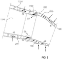
- FIG. 3 illustrates a flow of compressed cooling air A1 and A2 through a typical double-wall cooling path structure of a duct assembly in the combustor 1200.
- the duct assembly has a double-wall structure in which the flow sleeve 1270 surrounds the liner 1250 and the transition piece 1260, which are connected by means of the elastic support 1280.
- the elastic support 1280 may be formed of a metallic material, such as that of a hula seal in an embodiment, to support the liner 1250 and the transition piece 1260 with a structure capable of accommodating longitudinal and radial extension due to heat expansion.
- a seal area SA is an area including the elastic support 1280 and a partial area of each of the liner 1250 and the transition piece 1260 supported by the elastic support 1280 so that the partial areas are affected by a structural impact by the elastic support.
- the seal area SA which is in immediate proximity to the elastic support 1280, includes the partial areas relative to rear and front sides of the liner 1250 and the transition piece 1260.
- the seal area SA may include areas surrounding the ring-type elastic support 1280 to include rear and front sections of the liner 1250 and the transition piece 1260 in proximity to the elastic support.
- a portion of compressed air A discharged from the compressor 1100 of the gas turbine 1000 approaches the flow sleeve 1270 radially from a central shaft (rotor shaft) (i.e., upward from the bottom side in FIG. 2 ) in order to cool the duct assembly, particularly the transition piece 1260, which is heated by hot combustion gas.
- Such compressed air A is introduced into and flows through a space 300 in the double-wall structure of the duct assembly through cooling holes formed in an outer surface of the flow sleeve 1270 so as to cool the hot transition piece 1270 and the liner 1250 according to the cooling path structure (see flows A1 and A2 in FIG. 3 ).
- the seal areas SA positioned at the rear and front ends of the liner 1250 and the transition piece 1260 is not subjected to sufficient cooling, since the compressed air A1 is introduced into the space of the double-wall structure through the cooling holes 100 of the flow sleeve 1270 in proximity to a middle or rear portion of the transition piece 1260 and simply flows upstream past the seal area.
- the efficiency of cooling of the seal area SA is further degraded, since the compressed air A2 introduced into the space 300 of the double-wall structure through the cooling holes 200 of the flow sleeve 1270 in proximity to the liner 1250 offsets the pressure of the compressed air A1 flowing upstream along the space 300 while flowing downstream along the space 300.
- a cooling path structure applied to a guide plate 10 for concentrated cooling, which faces the seal area SA, and the flow sleeve 1270 including the guide plate is provided.
- the cooling path structure will be described in detail as follows.
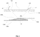
- FIG. 4 shows a duct assembly employing a cooling path structure for concentrated cooling of a seal area according to an embodiment of the present invention.
- FIGS. 5A and 5B show the concentrated cooling effect of the seal area using the cooling path structure for cooling of the seal area.
- a guide plate 10 for concentrated cooling facing the seal area SA is provided with first cooling holes 110 and second cooling holes 120, which are separated in an axial direction of the combustor 1200 or the transition piece 1270.
- the first cooling holes 110 are spaced apart at regular intervals along a first circumferential line, which lies on the guide plate 10 behind a central axis xm of the seal area SA (or upstream, in a direction of a flow of the compressed air), while passing through the guide plate 10 along a first inlet axis x1 inclined towards the central axis xm of the seal area SA, so that the compressed cooling air can be introduced in a forward direction towards the seal area SA (see FIG. 5A ).
- the second cooling holes 120 are spaced apart at regular intervals along a second circumferential line, which lies on the guide plate 10 in front of the central axis xm of the seal area SA (or downstream, in a direction of a flow of the compressed air), while passing through the guide plate 10 along a second inlet axis x2 inclined towards the central axis xm of the seal area SA, so that the compressed cooling air can be introduced in a backward direction towards the seal area SA (see FIG. 5B ).
- the guide plate 10 facing the seal area SA has, in tandem, first and second cooling holes 110 and 120, through which the compressed air is introduced to travel toward and impact the seal area SA in forward and backward directions simultaneously.
- the compressed air swirls around the seal area including the rear and front sides of the liner 1250 and the transition piece 1260, to which a seal (or an elastic support) is coupled, thereby maximizing the residence time of the compressed air around the seal area SA.
- first and second inlet axes x1 and x2 are each inclined towards the central axis xm of the seal area SA, preferably in a symmetric form relative to the central axis xm of the seal area SA.
- the guide plate 10 has, on its front and rear sides, first and second cooling holes 110 and 120 inclined towards the central axis xm of the seal area, so that the forward and backward flows of the compressed air can collide with each other and so that the pressure drop of the compressed air introduced around the seal area in the forward and backward directions can be restricted as well.
- a cooling hole guide 420 is provided around the second cooling hole 120 to increase a collected amount of the compressed air in preparation for a reduction in a flow rate of the compressed air flowing upstream through the space 300 of the double-wall structure, thereby ensuring a sufficient amount of a backward flow of the compressed air introduced for concentrated cooling of the seal area SA.
- a cooling hole guide 410 is also provided around the first cooling hole 110 to regulate an amount of a forward flow of the compressed air.
- the cooling hole guides 410 and 420 may have any shape, so long as it is provided on the guide plate 10 to collect the compressed air A flowing upstream through the space 300 of the double-wall structure.
- one or both of the cooling hole guides 410 and 420 may be configured as a spherical scoop, a bent or stepped part, or the like.
- the cooling hole guide (410 or 420) as a spherical scoop may include a curved attachment around the perimeter of the cooling hole (110 or 120), a bent concave cover protruding from the curved attachment and having a predefined inlet diameter, and a collecting part provided in the cover, wherein the collecting part has an opening directed towards an introduction direction of the compressed cooling air.
- the cooling hole guide (410 or 420) as a stepped part may be provided only on a front edge of the cooling hole (110 or 120) and may protrude upwardly.
- the cooling hole guide 420 of the second cooling hole 120 extends higher than the cooling hole guide 410 of the first cooling hole 110 from the guide plate 10. That is, since the compressed air A flowing upstream through the space 300 of the double-wall structure sequentially reaches the first cooling hole 110 and then the second cooling hole 120, the cooling hole guide 420 of the second cooling hole 120 is designed to have an inlet diameter larger than that of the cooling hole guide 410 of the first cooling hole 110, so that the cooling hole guide 420 of the second cooling hole 420 can collect a sufficient amount of compressed air. This contributes to homogeneous concentration of the compressed air A, a flow rate of which decreases as it flows upstream.
- FIG. 6 shows an arrangement of cooling holes in the cooling path structure for concentrated cooling of the seal area.
- the first cooling holes 110 which are circumferentially provided at regular intervals along the first circumferential line around the guide plate 10 behind the central axis xm of the seal area SA (right side in the drawing)
- the second cooling holes 120 which are circumferentially provided at regular intervals along the second circumferential line around the guide plate 10 in front of the central axis xm of the seal area SA (left side in the drawing)
- first and second cooling holes 110 and 120 has an effect of separating a flow of the compressed air introduced into the first cooling holes 110 on the downstream side and a flow of the compressed air introduced into the second cooling holes 120 on the upstream side, contributing to homogeneous distribution of the compressed air introduced into the first and second cooling holes 110 and 120.
- FIG. 7 shows a duct assembly employing a cooling path structure for concentrated cooling of a seal area according to another embodiment of the present invention.
- the guide plate 10 has a plurality of first cooling holes 110 along at least two first circumferential lines, wherein the first cooling holes 110 along respective circumferential lines are inclined towards the central axis xm of the seal area SA along respective inlet axes x1 and x1' such that a forward flow of the compressed air is introduced towards the central axis xm of the seal area, wherein the respective inlet axes x1 and x1' have different acute angles relative to the central axis xm of the seal area.
- the first cooling holes 110 are provided on the guide plate 10 behind the central axis xm of the seal area SA along two first circumferential lines, i.e., forward and rearward circumferential lines.
- the first cooling holes 110 along the forward and rearward circumferential lines are inclined at different acute angles relative to the central axis xm of the seal area SA, namely, along the inlet axes x1 and x1', wherein the acute angle of the inlet axis x1 relative to the central axis may be smaller than that of the inlet axis x1' relative to the central axis.
- the guide plate 10 may have a plurality of second cooling holes 120 along at least two second circumferential lines (not shown).
- the second cooling holes 120 along respective circumferential lines are also inclined towards the central axis xm of the seal area SA along respective second inlet axes x2 such that a backward flow of compressed air is introduced towards the central axis xm of the seal area, wherein the respective inlet axes x2 have different acute angles relative to the central axis xm of the seal area.
- the second cooling holes may be arranged in symmetric form with respect to the first cooling holes 110 relative to the central axis xm of the seal area.
- FIG. 7 shows that the first cooling holes 110 and/or the second cooling holes 120 may be respectively provided along two or more circumferential lines.
- cooling hole guides 410 and 420 provided along respective circumferential lines are designed to be higher (to have a large inlet diameter) as they are positioned forward (left side in the drawing), thereby ensuring homogeneous distribution of the compressed air introduced into the first/second cooling holes 110/120 on the downstream and upstream sides.
- FIG. 8 shows a duct assembly employing a cooling path structure for concentrated cooling of a seal area according to a further embodiment of the present invention.
- the first cooling hole 110 may be provided with a guide tube 430 such that the guide tube 430 protrudes through the guide plate 10 and extends toward the seal area SA, allowing the compressed cooling air to be introduced more closely to the seal area SA. It is preferred that the guide tube 430 be provided only in the first cooling hole 110, which is inclined in a forward direction towards the central axis xm of the seal area SA, so as not to interfere with a flow of compressed air A flowing upstream through the space 300 of the double-wall structure.
- the guide tube 430 may have a gradually decreasing inner diameter towards the central axis xm of the seal area SA, so that a flow rate of the compressed air can gradually increase as it approaches the seal area SA.
- the guide plate 10 may be circumferentially welded onto the flow sleeve 1270 such that cooling holes thereof are aligned with the cooling holes of the flow sleeve 1270, thereby being integrated with the flow sleeve.
- the provision of the cooling path structure in the duct assembly of a gas turbine combustor has an effect of inducing an impact of the compressed air on the seal area of the duct assembly, which is vulnerable to heat, thereby concentrating the cooling effect of the seal area.
- the provision of the cooling path structure in the duct assembly of a gas turbine combustor has an effect of removing destructive factors due to a pressure drop and a reduction in a flow rate of the compressed air flowing around the seal area of the duct assembly, thereby improving the efficiency of cooling of the seal area.
Landscapes
- Engineering & Computer Science (AREA)
- General Engineering & Computer Science (AREA)
- Mechanical Engineering (AREA)
- Chemical & Material Sciences (AREA)
- Combustion & Propulsion (AREA)
- Turbine Rotor Nozzle Sealing (AREA)
Claims (11)
- Kühlpfadstruktur zum konzentrierten Kühlen eines Dichtungsbereichs (SA) in einer Leitungsanordnung einer Gasturbinenbrennkammer (1200), wobei die Leitungsanordnung eine doppelwandige Struktur hat, bei der eine Durchflusshülse (1270) eine Ummantelung (1250) und ein Übergangsstück (1260) umgibt und einen inneren ringförmigen Raum (300) für eine Strömung von Druckluft zum Kühlen definiert, um die Ummantelung (1250) und das Übergangsstück (1260) zu kühlen, wobei die Ummantelung (1250) und das Übergangsstück (1260) mittels einer ringförmigen elastischen Halterung (1280) verbunden sind, wobei sich der Dichtungsbereich (SA) in der Nähe der elastischen Halterung (1280) befindet und jeweils eine hintere und eine vordere Seite der Ummantelung (1250) und des Übergangsstücks (1260) umschließt, wobei die Kühlpfadstruktur Folgendes umfasst:eine Führungsplatte (10) zum konzentrierten Kühlen, die zu dem Dichtungsbereich (SA) zeigt, um durch mehrere erste Kühllöcher (110) und mehrere zweite Kühllöcher (120), die jeweils in der Führungsplatte (10) ausgebildet sind, Druckluft zum Kühlen in den Dichtungsbereich (SA) zu leiten, wobei die Druckluft zum Kühlen durch den inneren ringförmigen Raum (300) stromaufwärts strömt und der Reihe nach die ersten Kühllöcher (110) und dann die zweiten Kühllöcher (120) erreicht;wobei die ersten Kühllöcher (110) längs einer ersten Eintrittsachse (x1) so ausgebildet sind, dass sich die eingeleitete Kühlluft in einer Vorwärtsrichtung bezüglich einer Strömungsrichtung der Druckluft zum Kühlen in dem inneren ringförmigen Raum (300) einer Mittelachse (xm) des Dichtungsbereichs (SA) annähert, und wobei die zweiten Kühllöcher (120) längs einer zweiten Eintrittsachse (x2) so ausgebildet sind, dass sich die eingeleitete Kühlluft in einer Rückwärtsrichtung bezüglich der Strömungsrichtung der Druckluft zum Kühlen in dem ringförmigen Raum (300) der Mittelachse (xm) des Dichtungsbereichs (SA) annähert;wobei die Kühlpfadstruktur ferner eine erste und eine zweite Kühllochführung (410, 420) umfasst, die von der Führungsplatte (10) in der Nähe der ersten bzw. der zweiten Kühllöcher (110, 120) vorstehen, wobei die zweite Kühllochführung (420) höher als die erste Kühllochführung (410) vorsteht.
- Kühlpfadstruktur nach Anspruch 1, wobei die erste und die zweite Eintrittsachse (x1, x2) bezüglich der Mittelachse (xm) des Dichtungsbereichs (SA) symmetrisch sind.
- Kühlpfadstruktur nach Anspruch 1, die ferner ein Führungsrohr (430) umfasst, das für die ersten Kühllöcher (110) vorgesehen ist, wobei das Führungsrohr (430) durch die Führungsplatte (10) vorsteht und sich in Richtung des Dichtungsbereichs (SA) erstreckt.
- Kühlpfadstruktur nach Anspruch 3, wobei das Führungsrohr (430) einen abnehmenden Innendurchmesser in Richtung der Mittelachse (xm) des Dichtungsbereichs (SA) aufweist.
- Kühlpfadstruktur nach Anspruch 1, wobei die erste und die zweite Eintrittsachse (x1, x2) in Bezug auf die Mittelachse (xm) des Dichtungsbereichs (SA) in einem spitzen Winkel geneigt sind.
- Kühlpfadstruktur nach Anspruch 5, wobei die ersten Kühllöcher (110), die in der Führungsplatte (10) ausgebildet sind, entlang wenigstens zweier Umfangslinien angeordnet sind, und
wobei die erste Eintrittsachse (x1) für die ersten Kühllöcher (110) der jeweiligen Umfangslinien in einem unterschiedlichen spitzen Winkel geneigt ist. - Kühlpfadstruktur nach Anspruch 1, wobei die Führungsplatte (10) mit der Durchflusshülse (1270) einteilig ausgebildet ist.
- Kühlpfadstruktur nach Anspruch 1, wobei die ersten Kühllöcher (110) entlang einer ersten Umfangslinie, die auf der Führungsplatte (10) liegt, stromaufwärts der Mittelachse (xm) in Bezug auf die Strömungsrichtung der Druckluft zum Kühlen in dem inneren ringförmigen Raum (300) in regelmäßigen Abständen beabstandet sind, wobei sie durch die Führungsplatte (10) längs der ersten Eintrittsachse (x1) verlaufen;
und wobei die zweiten Kühllöcher (120) entlang einer zweiten Umfangslinie, die auf der Führungsplatte (10) liegt, stromabwärts der Mittelachse (xm) in Bezug auf die Strömungsrichtung der Druckluft zum Kühlen in dem inneren ringförmigen Raum (300) in regelmäßigen Abständen beabstandet sind, wobei sie durch die Führungsplatte (10) längs der zweiten Eintrittsachse (x2) verlaufen. - Kühlpfadstruktur nach Anspruch 8, wobei die ersten Kühllöcher (110) auf der ersten Umfangslinie in Bezug auf die zweiten Kühllöcher (120), die auf der zweiten Umfangslinie in einer Umfangsrichtung der Leitungsanordnung angeordnet sind, abwechselnd angeordnet sind.
- Kühlpfadstruktur nach Anspruch 1, wobei der Dichtungsbereich (SA) zwischen der ersten und der zweiten Umfangslinie verläuft.
- Brennkammer (1200) einer Gasturbine (1000), wobei die Brennkammer (1200) Folgendes umfasst:
eine Leitungsanordnung, die eine Kühlpfadstruktur hat, um die Leitungsanordnung zu kühlen, die durch heißes Brenngas erhitzt wird, wobei die Kühlpfadstruktur eine Kühlpfadstruktur nach einem der vorhergehenden Ansprüche ist.
Applications Claiming Priority (1)
| Application Number | Priority Date | Filing Date | Title |
|---|---|---|---|
| KR1020170106058A KR101986729B1 (ko) | 2017-08-22 | 2017-08-22 | 실 영역 집중냉각을 위한 냉각유로 구조 및 이를 포함하는 가스 터빈용 연소기 |
Publications (2)
| Publication Number | Publication Date |
|---|---|
| EP3447381A1 EP3447381A1 (de) | 2019-02-27 |
| EP3447381B1 true EP3447381B1 (de) | 2021-06-16 |
Family
ID=62874638
Family Applications (1)
| Application Number | Title | Priority Date | Filing Date |
|---|---|---|---|
| EP18181893.1A Active EP3447381B1 (de) | 2017-08-22 | 2018-07-05 | Kühlpfadstruktur zur konzentrierten kühlung eines dichtungsbereichs und gasturbinenbrennkammer damit |
Country Status (3)
| Country | Link |
|---|---|
| US (1) | US10830143B2 (de) |
| EP (1) | EP3447381B1 (de) |
| KR (1) | KR101986729B1 (de) |
Families Citing this family (13)
| Publication number | Priority date | Publication date | Assignee | Title |
|---|---|---|---|---|
| KR102164620B1 (ko) | 2019-06-19 | 2020-10-12 | 두산중공업 주식회사 | 연소기 및 이를 포함하는 가스터빈 |
| US11371701B1 (en) | 2021-02-03 | 2022-06-28 | General Electric Company | Combustor for a gas turbine engine |
| US11959643B2 (en) | 2021-06-07 | 2024-04-16 | General Electric Company | Combustor for a gas turbine engine |
| US12146660B2 (en) | 2021-06-07 | 2024-11-19 | General Electric Company | Combustor for a gas turbine engine |
| US11885495B2 (en) | 2021-06-07 | 2024-01-30 | General Electric Company | Combustor for a gas turbine engine including a liner having a looped feature |
| US12085283B2 (en) | 2021-06-07 | 2024-09-10 | General Electric Company | Combustor for a gas turbine engine |
| US11774098B2 (en) | 2021-06-07 | 2023-10-03 | General Electric Company | Combustor for a gas turbine engine |
| US12152777B2 (en) | 2021-06-07 | 2024-11-26 | General Electric Company | Combustor for a gas turbine engine |
| CN116221774B (zh) | 2021-12-06 | 2025-09-09 | 通用电气公司 | 用于燃烧器衬里的变化的稀释孔设计 |
| US12055058B2 (en) * | 2022-05-31 | 2024-08-06 | Pratt & Whitney Canada Corp. | Joint between gas turbine engine components with a spring element |
| KR102849521B1 (ko) * | 2023-11-30 | 2025-08-21 | 두산에너빌리티 주식회사 | 연소기용 노즐, 연소기, 및 이를 포함하는 가스 터빈 |
| KR102863422B1 (ko) * | 2023-12-08 | 2025-09-22 | 두산에너빌리티 주식회사 | 연소기용 노즐, 연소기, 및 이를 포함하는 가스 터빈 |
| CN117704077B (zh) * | 2024-02-06 | 2024-04-12 | 中国空气动力研究与发展中心空天技术研究所 | 一种硬连接密封位置补偿结构 |
Citations (1)
| Publication number | Priority date | Publication date | Assignee | Title |
|---|---|---|---|---|
| KR101766449B1 (ko) * | 2016-06-16 | 2017-08-08 | 두산중공업 주식회사 | 공기유도 캡 및 이를 구비하는 연소 덕트 |
Family Cites Families (32)
| Publication number | Priority date | Publication date | Assignee | Title |
|---|---|---|---|---|
| US3581492A (en) * | 1969-07-08 | 1971-06-01 | Nasa | Gas turbine combustor |
| US4192138A (en) * | 1977-08-29 | 1980-03-11 | Westinghouse Electric Corp. | Gas turbine combustor air inlet |
| US5333443A (en) * | 1993-02-08 | 1994-08-02 | General Electric Company | Seal assembly |
| JP3590666B2 (ja) | 1995-03-30 | 2004-11-17 | 株式会社東芝 | ガスタービン燃焼器 |
| GB2326706A (en) * | 1997-06-25 | 1998-12-30 | Europ Gas Turbines Ltd | Heat transfer structure |
| US6494044B1 (en) * | 1999-11-19 | 2002-12-17 | General Electric Company | Aerodynamic devices for enhancing sidepanel cooling on an impingement cooled transition duct and related method |
| US6484505B1 (en) | 2000-02-25 | 2002-11-26 | General Electric Company | Combustor liner cooling thimbles and related method |
| US7096668B2 (en) * | 2003-12-22 | 2006-08-29 | Martling Vincent C | Cooling and sealing design for a gas turbine combustion system |
| US7010921B2 (en) * | 2004-06-01 | 2006-03-14 | General Electric Company | Method and apparatus for cooling combustor liner and transition piece of a gas turbine |
| FR2899315B1 (fr) * | 2006-03-30 | 2012-09-28 | Snecma | Configuration d'ouvertures de dilution dans une paroi de chambre de combustion de turbomachine |
| US8281600B2 (en) * | 2007-01-09 | 2012-10-09 | General Electric Company | Thimble, sleeve, and method for cooling a combustor assembly |
| US8544277B2 (en) * | 2007-09-28 | 2013-10-01 | General Electric Company | Turbulated aft-end liner assembly and cooling method |
| US9046269B2 (en) | 2008-07-03 | 2015-06-02 | Pw Power Systems, Inc. | Impingement cooling device |
| US8166764B2 (en) * | 2008-07-21 | 2012-05-01 | United Technologies Corporation | Flow sleeve impingement cooling using a plenum ring |
| US8291711B2 (en) * | 2008-07-25 | 2012-10-23 | United Technologies Corporation | Flow sleeve impingement cooling baffles |
| US8677759B2 (en) | 2009-01-06 | 2014-03-25 | General Electric Company | Ring cooling for a combustion liner and related method |
| US7926283B2 (en) * | 2009-02-26 | 2011-04-19 | General Electric Company | Gas turbine combustion system cooling arrangement |
| US20100223931A1 (en) * | 2009-03-04 | 2010-09-09 | General Electric Company | Pattern cooled combustor liner |
| US8307657B2 (en) * | 2009-03-10 | 2012-11-13 | General Electric Company | Combustor liner cooling system |
| US20100269513A1 (en) * | 2009-04-23 | 2010-10-28 | General Electric Company | Thimble Fan for a Combustion System |
| US8359867B2 (en) | 2010-04-08 | 2013-01-29 | General Electric Company | Combustor having a flow sleeve |
| US8276391B2 (en) * | 2010-04-19 | 2012-10-02 | General Electric Company | Combustor liner cooling at transition duct interface and related method |
| CH703657A1 (de) | 2010-08-27 | 2012-02-29 | Alstom Technology Ltd | Verfahren zum betrieb einer brenneranordnung sowie brenneranordnung zur durchführung des verfahrens. |
| US8813501B2 (en) * | 2011-01-03 | 2014-08-26 | General Electric Company | Combustor assemblies for use in turbine engines and methods of assembling same |
| US20120180500A1 (en) * | 2011-01-13 | 2012-07-19 | General Electric Company | System for damping vibration in a gas turbine engine |
| US9127551B2 (en) * | 2011-03-29 | 2015-09-08 | Siemens Energy, Inc. | Turbine combustion system cooling scoop |
| US8955331B2 (en) * | 2011-05-20 | 2015-02-17 | Siemens Energy, Inc. | Turbine combustion system coupling with adjustable wear pad |
| US20130086915A1 (en) * | 2011-10-07 | 2013-04-11 | General Electric Company | Film cooled combustion liner assembly |
| DE102012016493A1 (de) | 2012-08-21 | 2014-02-27 | Rolls-Royce Deutschland Ltd & Co Kg | Gasturbinenbrennkammer mit prallgekühlten Bolzen der Brennkammerschindeln |
| US10215418B2 (en) * | 2014-10-13 | 2019-02-26 | Ansaldo Energia Ip Uk Limited | Sealing device for a gas turbine combustor |
| KR101843961B1 (ko) * | 2015-05-27 | 2018-03-30 | 두산중공업 주식회사 | 회전가능한 공기유도캡이 마련된 연소기 챔버. |
| US9995221B2 (en) * | 2015-12-22 | 2018-06-12 | General Electric Company | Staged fuel and air injection in combustion systems of gas turbines |
-
2017
- 2017-08-22 KR KR1020170106058A patent/KR101986729B1/ko active Active
-
2018
- 2018-07-03 US US16/026,065 patent/US10830143B2/en active Active
- 2018-07-05 EP EP18181893.1A patent/EP3447381B1/de active Active
Patent Citations (1)
| Publication number | Priority date | Publication date | Assignee | Title |
|---|---|---|---|---|
| KR101766449B1 (ko) * | 2016-06-16 | 2017-08-08 | 두산중공업 주식회사 | 공기유도 캡 및 이를 구비하는 연소 덕트 |
Also Published As
| Publication number | Publication date |
|---|---|
| US10830143B2 (en) | 2020-11-10 |
| EP3447381A1 (de) | 2019-02-27 |
| US20190063320A1 (en) | 2019-02-28 |
| KR20190021013A (ko) | 2019-03-05 |
| KR101986729B1 (ko) | 2019-06-07 |
Similar Documents
| Publication | Publication Date | Title |
|---|---|---|
| US10830143B2 (en) | Cooling path structure for concentrated cooling of seal area and gas turbine combustor having the same | |
| EP1253379B1 (de) | Verfahren und Vorrichtung zur Kühlung von Gasturbinenbrennkammern | |
| US7104067B2 (en) | Combustor liner with inverted turbulators | |
| CN101799162B (zh) | 用于涡轮机的束状多管式喷嘴 | |
| US8893382B2 (en) | Combustion system and method of assembling the same | |
| EP1253380A2 (de) | Verfahren und Vorrichtung zur Kühlung von Gasturbinenbrennkammern | |
| EP1258681B1 (de) | Verfahren und Vorrichtung zur Kühlung einer Gasturbinenverbrennungskammer | |
| US10995958B2 (en) | Pilot fuel injector, and fuel nozzle and gas turbine having same | |
| US20180347586A1 (en) | Vane ring assembly and compressor and gas turbine including the same | |
| CN107191970B (zh) | 燃气涡轮流套管安装 | |
| EP3889508B1 (de) | Gasturbinenbrennkammer | |
| EP2230456A2 (de) | Brennermantel mit Mischlochansatz | |
| JP6599167B2 (ja) | 燃焼器キャップ組立体 | |
| US11953205B2 (en) | Swirler with fuel manifold, and combustor and gas turbine including the same | |
| US10837296B2 (en) | Air-collecting structure for enhancing cooling performance for transition piece and gas turbine combustor having same | |
| JP2016044680A (ja) | 燃焼器キャップ組立体 | |
| JP7271232B2 (ja) | 環状燃焼器ライナの遷移ゾーン用の内側冷却シュラウド | |
| EP4224065B1 (de) | Mikromischer und gasturbine damit | |
| EP3477203B1 (de) | Brennkammer und gasturbine damit | |
| EP4067746B1 (de) | Brennkammer mit nachlauferreger | |
| US7360364B2 (en) | Method and apparatus for assembling gas turbine engine combustors | |
| US11242990B2 (en) | Liner cooling structure with reduced pressure losses and gas turbine combustor having same | |
| US20160116167A1 (en) | D5/d5a df-42 double walled exit cone and splash plate |
Legal Events
| Date | Code | Title | Description |
|---|---|---|---|
| PUAI | Public reference made under article 153(3) epc to a published international application that has entered the european phase |
Free format text: ORIGINAL CODE: 0009012 |
|
| STAA | Information on the status of an ep patent application or granted ep patent |
Free format text: STATUS: REQUEST FOR EXAMINATION WAS MADE |
|
| 17P | Request for examination filed |
Effective date: 20180705 |
|
| AK | Designated contracting states |
Kind code of ref document: A1 Designated state(s): AL AT BE BG CH CY CZ DE DK EE ES FI FR GB GR HR HU IE IS IT LI LT LU LV MC MK MT NL NO PL PT RO RS SE SI SK SM TR |
|
| AX | Request for extension of the european patent |
Extension state: BA ME |
|
| RBV | Designated contracting states (corrected) |
Designated state(s): AL AT BE BG CH CY CZ DE DK EE ES FI FR GB GR HR HU IE IS IT LI LT LU LV MC MK MT NL NO PL PT RO RS SE SI SK SM TR |
|
| GRAP | Despatch of communication of intention to grant a patent |
Free format text: ORIGINAL CODE: EPIDOSNIGR1 |
|
| STAA | Information on the status of an ep patent application or granted ep patent |
Free format text: STATUS: GRANT OF PATENT IS INTENDED |
|
| INTG | Intention to grant announced |
Effective date: 20210222 |
|
| GRAS | Grant fee paid |
Free format text: ORIGINAL CODE: EPIDOSNIGR3 |
|
| GRAA | (expected) grant |
Free format text: ORIGINAL CODE: 0009210 |
|
| STAA | Information on the status of an ep patent application or granted ep patent |
Free format text: STATUS: THE PATENT HAS BEEN GRANTED |
|
| AK | Designated contracting states |
Kind code of ref document: B1 Designated state(s): AL AT BE BG CH CY CZ DE DK EE ES FI FR GB GR HR HU IE IS IT LI LT LU LV MC MK MT NL NO PL PT RO RS SE SI SK SM TR |
|
| REG | Reference to a national code |
Ref country code: GB Ref legal event code: FG4D |
|
| REG | Reference to a national code |
Ref country code: CH Ref legal event code: EP |
|
| REG | Reference to a national code |
Ref country code: DE Ref legal event code: R096 Ref document number: 602018018555 Country of ref document: DE |
|
| REG | Reference to a national code |
Ref country code: AT Ref legal event code: REF Ref document number: 1402641 Country of ref document: AT Kind code of ref document: T Effective date: 20210715 |
|
| REG | Reference to a national code |
Ref country code: IE Ref legal event code: FG4D |
|
| REG | Reference to a national code |
Ref country code: LT Ref legal event code: MG9D |
|
| PG25 | Lapsed in a contracting state [announced via postgrant information from national office to epo] |
Ref country code: FI Free format text: LAPSE BECAUSE OF FAILURE TO SUBMIT A TRANSLATION OF THE DESCRIPTION OR TO PAY THE FEE WITHIN THE PRESCRIBED TIME-LIMIT Effective date: 20210616 Ref country code: HR Free format text: LAPSE BECAUSE OF FAILURE TO SUBMIT A TRANSLATION OF THE DESCRIPTION OR TO PAY THE FEE WITHIN THE PRESCRIBED TIME-LIMIT Effective date: 20210616 Ref country code: LT Free format text: LAPSE BECAUSE OF FAILURE TO SUBMIT A TRANSLATION OF THE DESCRIPTION OR TO PAY THE FEE WITHIN THE PRESCRIBED TIME-LIMIT Effective date: 20210616 Ref country code: BG Free format text: LAPSE BECAUSE OF FAILURE TO SUBMIT A TRANSLATION OF THE DESCRIPTION OR TO PAY THE FEE WITHIN THE PRESCRIBED TIME-LIMIT Effective date: 20210916 |
|
| REG | Reference to a national code |
Ref country code: AT Ref legal event code: MK05 Ref document number: 1402641 Country of ref document: AT Kind code of ref document: T Effective date: 20210616 |
|
| REG | Reference to a national code |
Ref country code: NL Ref legal event code: MP Effective date: 20210616 |
|
| PG25 | Lapsed in a contracting state [announced via postgrant information from national office to epo] |
Ref country code: GR Free format text: LAPSE BECAUSE OF FAILURE TO SUBMIT A TRANSLATION OF THE DESCRIPTION OR TO PAY THE FEE WITHIN THE PRESCRIBED TIME-LIMIT Effective date: 20210917 Ref country code: SE Free format text: LAPSE BECAUSE OF FAILURE TO SUBMIT A TRANSLATION OF THE DESCRIPTION OR TO PAY THE FEE WITHIN THE PRESCRIBED TIME-LIMIT Effective date: 20210616 Ref country code: RS Free format text: LAPSE BECAUSE OF FAILURE TO SUBMIT A TRANSLATION OF THE DESCRIPTION OR TO PAY THE FEE WITHIN THE PRESCRIBED TIME-LIMIT Effective date: 20210616 Ref country code: LV Free format text: LAPSE BECAUSE OF FAILURE TO SUBMIT A TRANSLATION OF THE DESCRIPTION OR TO PAY THE FEE WITHIN THE PRESCRIBED TIME-LIMIT Effective date: 20210616 Ref country code: NO Free format text: LAPSE BECAUSE OF FAILURE TO SUBMIT A TRANSLATION OF THE DESCRIPTION OR TO PAY THE FEE WITHIN THE PRESCRIBED TIME-LIMIT Effective date: 20210916 |
|
| PG25 | Lapsed in a contracting state [announced via postgrant information from national office to epo] |
Ref country code: SM Free format text: LAPSE BECAUSE OF FAILURE TO SUBMIT A TRANSLATION OF THE DESCRIPTION OR TO PAY THE FEE WITHIN THE PRESCRIBED TIME-LIMIT Effective date: 20210616 Ref country code: SK Free format text: LAPSE BECAUSE OF FAILURE TO SUBMIT A TRANSLATION OF THE DESCRIPTION OR TO PAY THE FEE WITHIN THE PRESCRIBED TIME-LIMIT Effective date: 20210616 Ref country code: ES Free format text: LAPSE BECAUSE OF FAILURE TO SUBMIT A TRANSLATION OF THE DESCRIPTION OR TO PAY THE FEE WITHIN THE PRESCRIBED TIME-LIMIT Effective date: 20210616 Ref country code: EE Free format text: LAPSE BECAUSE OF FAILURE TO SUBMIT A TRANSLATION OF THE DESCRIPTION OR TO PAY THE FEE WITHIN THE PRESCRIBED TIME-LIMIT Effective date: 20210616 Ref country code: AT Free format text: LAPSE BECAUSE OF FAILURE TO SUBMIT A TRANSLATION OF THE DESCRIPTION OR TO PAY THE FEE WITHIN THE PRESCRIBED TIME-LIMIT Effective date: 20210616 Ref country code: CZ Free format text: LAPSE BECAUSE OF FAILURE TO SUBMIT A TRANSLATION OF THE DESCRIPTION OR TO PAY THE FEE WITHIN THE PRESCRIBED TIME-LIMIT Effective date: 20210616 Ref country code: NL Free format text: LAPSE BECAUSE OF FAILURE TO SUBMIT A TRANSLATION OF THE DESCRIPTION OR TO PAY THE FEE WITHIN THE PRESCRIBED TIME-LIMIT Effective date: 20210616 Ref country code: PT Free format text: LAPSE BECAUSE OF FAILURE TO SUBMIT A TRANSLATION OF THE DESCRIPTION OR TO PAY THE FEE WITHIN THE PRESCRIBED TIME-LIMIT Effective date: 20211018 Ref country code: RO Free format text: LAPSE BECAUSE OF FAILURE TO SUBMIT A TRANSLATION OF THE DESCRIPTION OR TO PAY THE FEE WITHIN THE PRESCRIBED TIME-LIMIT Effective date: 20210616 |
|
| PG25 | Lapsed in a contracting state [announced via postgrant information from national office to epo] |
Ref country code: PL Free format text: LAPSE BECAUSE OF FAILURE TO SUBMIT A TRANSLATION OF THE DESCRIPTION OR TO PAY THE FEE WITHIN THE PRESCRIBED TIME-LIMIT Effective date: 20210616 |
|
| REG | Reference to a national code |
Ref country code: CH Ref legal event code: PL |
|
| REG | Reference to a national code |
Ref country code: DE Ref legal event code: R097 Ref document number: 602018018555 Country of ref document: DE |
|
| PG25 | Lapsed in a contracting state [announced via postgrant information from national office to epo] |
Ref country code: MC Free format text: LAPSE BECAUSE OF FAILURE TO SUBMIT A TRANSLATION OF THE DESCRIPTION OR TO PAY THE FEE WITHIN THE PRESCRIBED TIME-LIMIT Effective date: 20210616 |
|
| REG | Reference to a national code |
Ref country code: BE Ref legal event code: MM Effective date: 20210731 |
|
| PLBE | No opposition filed within time limit |
Free format text: ORIGINAL CODE: 0009261 |
|
| STAA | Information on the status of an ep patent application or granted ep patent |
Free format text: STATUS: NO OPPOSITION FILED WITHIN TIME LIMIT |
|
| PG25 | Lapsed in a contracting state [announced via postgrant information from national office to epo] |
Ref country code: LI Free format text: LAPSE BECAUSE OF NON-PAYMENT OF DUE FEES Effective date: 20210731 Ref country code: DK Free format text: LAPSE BECAUSE OF FAILURE TO SUBMIT A TRANSLATION OF THE DESCRIPTION OR TO PAY THE FEE WITHIN THE PRESCRIBED TIME-LIMIT Effective date: 20210616 Ref country code: CH Free format text: LAPSE BECAUSE OF NON-PAYMENT OF DUE FEES Effective date: 20210731 |
|
| 26N | No opposition filed |
Effective date: 20220317 |
|
| PG25 | Lapsed in a contracting state [announced via postgrant information from national office to epo] |
Ref country code: LU Free format text: LAPSE BECAUSE OF NON-PAYMENT OF DUE FEES Effective date: 20210705 Ref country code: AL Free format text: LAPSE BECAUSE OF FAILURE TO SUBMIT A TRANSLATION OF THE DESCRIPTION OR TO PAY THE FEE WITHIN THE PRESCRIBED TIME-LIMIT Effective date: 20210616 |
|
| PG25 | Lapsed in a contracting state [announced via postgrant information from national office to epo] |
Ref country code: IT Free format text: LAPSE BECAUSE OF FAILURE TO SUBMIT A TRANSLATION OF THE DESCRIPTION OR TO PAY THE FEE WITHIN THE PRESCRIBED TIME-LIMIT Effective date: 20210616 Ref country code: IE Free format text: LAPSE BECAUSE OF NON-PAYMENT OF DUE FEES Effective date: 20210705 Ref country code: FR Free format text: LAPSE BECAUSE OF NON-PAYMENT OF DUE FEES Effective date: 20210816 Ref country code: BE Free format text: LAPSE BECAUSE OF NON-PAYMENT OF DUE FEES Effective date: 20210731 |
|
| GBPC | Gb: european patent ceased through non-payment of renewal fee |
Effective date: 20220705 |
|
| PG25 | Lapsed in a contracting state [announced via postgrant information from national office to epo] |
Ref country code: GB Free format text: LAPSE BECAUSE OF NON-PAYMENT OF DUE FEES Effective date: 20220705 |
|
| PG25 | Lapsed in a contracting state [announced via postgrant information from national office to epo] |
Ref country code: CY Free format text: LAPSE BECAUSE OF FAILURE TO SUBMIT A TRANSLATION OF THE DESCRIPTION OR TO PAY THE FEE WITHIN THE PRESCRIBED TIME-LIMIT Effective date: 20210616 |
|
| PG25 | Lapsed in a contracting state [announced via postgrant information from national office to epo] |
Ref country code: HU Free format text: LAPSE BECAUSE OF FAILURE TO SUBMIT A TRANSLATION OF THE DESCRIPTION OR TO PAY THE FEE WITHIN THE PRESCRIBED TIME-LIMIT; INVALID AB INITIO Effective date: 20180705 |
|
| PG25 | Lapsed in a contracting state [announced via postgrant information from national office to epo] |
Ref country code: MK Free format text: LAPSE BECAUSE OF FAILURE TO SUBMIT A TRANSLATION OF THE DESCRIPTION OR TO PAY THE FEE WITHIN THE PRESCRIBED TIME-LIMIT Effective date: 20210616 |
|
| PG25 | Lapsed in a contracting state [announced via postgrant information from national office to epo] |
Ref country code: MT Free format text: LAPSE BECAUSE OF FAILURE TO SUBMIT A TRANSLATION OF THE DESCRIPTION OR TO PAY THE FEE WITHIN THE PRESCRIBED TIME-LIMIT Effective date: 20210616 |
|
| PGFP | Annual fee paid to national office [announced via postgrant information from national office to epo] |
Ref country code: DE Payment date: 20250528 Year of fee payment: 8 |
|
| PG25 | Lapsed in a contracting state [announced via postgrant information from national office to epo] |
Ref country code: TR Free format text: LAPSE BECAUSE OF FAILURE TO SUBMIT A TRANSLATION OF THE DESCRIPTION OR TO PAY THE FEE WITHIN THE PRESCRIBED TIME-LIMIT Effective date: 20210616 |