EP3447224A1 - Drehlager und verfahren zur montage eines solchen drehlagers - Google Patents
Drehlager und verfahren zur montage eines solchen drehlagers Download PDFInfo
- Publication number
- EP3447224A1 EP3447224A1 EP18185141.1A EP18185141A EP3447224A1 EP 3447224 A1 EP3447224 A1 EP 3447224A1 EP 18185141 A EP18185141 A EP 18185141A EP 3447224 A1 EP3447224 A1 EP 3447224A1
- Authority
- EP
- European Patent Office
- Prior art keywords
- bearing
- securing element
- bearing pin
- fork
- pivot bearing
- Prior art date
- Legal status (The legal status is an assumption and is not a legal conclusion. Google has not performed a legal analysis and makes no representation as to the accuracy of the status listed.)
- Granted
Links
Images

Classifications
-
- E—FIXED CONSTRUCTIONS
- E05—LOCKS; KEYS; WINDOW OR DOOR FITTINGS; SAFES
- E05D—HINGES OR SUSPENSION DEVICES FOR DOORS, WINDOWS OR WINGS
- E05D5/00—Construction of single parts, e.g. the parts for attachment
- E05D5/10—Pins, sockets or sleeves; Removable pins
- E05D5/12—Securing pins in sockets, movably or not
-
- E—FIXED CONSTRUCTIONS
- E05—LOCKS; KEYS; WINDOW OR DOOR FITTINGS; SAFES
- E05D—HINGES OR SUSPENSION DEVICES FOR DOORS, WINDOWS OR WINGS
- E05D7/00—Hinges or pivots of special construction
- E05D7/10—Hinges or pivots of special construction to allow easy separation or connection of the parts at the hinge axis
- E05D7/1005—Hinges or pivots of special construction to allow easy separation or connection of the parts at the hinge axis by axially moving free pins, balls or sockets
- E05D7/1022—Hinges or pivots of special construction to allow easy separation or connection of the parts at the hinge axis by axially moving free pins, balls or sockets with snap-fitted pins
-
- E—FIXED CONSTRUCTIONS
- E05—LOCKS; KEYS; WINDOW OR DOOR FITTINGS; SAFES
- E05D—HINGES OR SUSPENSION DEVICES FOR DOORS, WINDOWS OR WINGS
- E05D7/00—Hinges or pivots of special construction
- E05D7/10—Hinges or pivots of special construction to allow easy separation or connection of the parts at the hinge axis
- E05D7/1044—Hinges or pivots of special construction to allow easy separation or connection of the parts at the hinge axis in an axial direction
- E05D7/1055—Hinges or pivots of special construction to allow easy separation or connection of the parts at the hinge axis in an axial direction with snap-fitted pins
-
- E—FIXED CONSTRUCTIONS
- E05—LOCKS; KEYS; WINDOW OR DOOR FITTINGS; SAFES
- E05D—HINGES OR SUSPENSION DEVICES FOR DOORS, WINDOWS OR WINGS
- E05D15/00—Suspension arrangements for wings
- E05D15/48—Suspension arrangements for wings allowing alternative movements
- E05D15/52—Suspension arrangements for wings allowing alternative movements for opening about a vertical as well as a horizontal axis
- E05D15/5214—Corner supports
-
- E—FIXED CONSTRUCTIONS
- E05—LOCKS; KEYS; WINDOW OR DOOR FITTINGS; SAFES
- E05Y—INDEXING SCHEME ASSOCIATED WITH SUBCLASSES E05D AND E05F, RELATING TO CONSTRUCTION ELEMENTS, ELECTRIC CONTROL, POWER SUPPLY, POWER SIGNAL OR TRANSMISSION, USER INTERFACES, MOUNTING OR COUPLING, DETAILS, ACCESSORIES, AUXILIARY OPERATIONS NOT OTHERWISE PROVIDED FOR, APPLICATION THEREOF
- E05Y2600/00—Mounting or coupling arrangements for elements provided for in this subclass
- E05Y2600/50—Mounting methods; Positioning
- E05Y2600/52—Toolless
- E05Y2600/53—Snapping
-
- E—FIXED CONSTRUCTIONS
- E05—LOCKS; KEYS; WINDOW OR DOOR FITTINGS; SAFES
- E05Y—INDEXING SCHEME ASSOCIATED WITH SUBCLASSES E05D AND E05F, RELATING TO CONSTRUCTION ELEMENTS, ELECTRIC CONTROL, POWER SUPPLY, POWER SIGNAL OR TRANSMISSION, USER INTERFACES, MOUNTING OR COUPLING, DETAILS, ACCESSORIES, AUXILIARY OPERATIONS NOT OTHERWISE PROVIDED FOR, APPLICATION THEREOF
- E05Y2600/00—Mounting or coupling arrangements for elements provided for in this subclass
- E05Y2600/60—Mounting or coupling members; Accessories therefor
- E05Y2600/63—Retainers
-
- E—FIXED CONSTRUCTIONS
- E05—LOCKS; KEYS; WINDOW OR DOOR FITTINGS; SAFES
- E05Y—INDEXING SCHEME ASSOCIATED WITH SUBCLASSES E05D AND E05F, RELATING TO CONSTRUCTION ELEMENTS, ELECTRIC CONTROL, POWER SUPPLY, POWER SIGNAL OR TRANSMISSION, USER INTERFACES, MOUNTING OR COUPLING, DETAILS, ACCESSORIES, AUXILIARY OPERATIONS NOT OTHERWISE PROVIDED FOR, APPLICATION THEREOF
- E05Y2800/00—Details, accessories and auxiliary operations not otherwise provided for
- E05Y2800/26—Form or shape
- E05Y2800/33—Form or shape having protrusions
-
- E—FIXED CONSTRUCTIONS
- E05—LOCKS; KEYS; WINDOW OR DOOR FITTINGS; SAFES
- E05Y—INDEXING SCHEME ASSOCIATED WITH SUBCLASSES E05D AND E05F, RELATING TO CONSTRUCTION ELEMENTS, ELECTRIC CONTROL, POWER SUPPLY, POWER SIGNAL OR TRANSMISSION, USER INTERFACES, MOUNTING OR COUPLING, DETAILS, ACCESSORIES, AUXILIARY OPERATIONS NOT OTHERWISE PROVIDED FOR, APPLICATION THEREOF
- E05Y2800/00—Details, accessories and auxiliary operations not otherwise provided for
- E05Y2800/34—Form stability
- E05Y2800/342—Deformable
- E05Y2800/344—Deformable elastically
-
- E—FIXED CONSTRUCTIONS
- E05—LOCKS; KEYS; WINDOW OR DOOR FITTINGS; SAFES
- E05Y—INDEXING SCHEME ASSOCIATED WITH SUBCLASSES E05D AND E05F, RELATING TO CONSTRUCTION ELEMENTS, ELECTRIC CONTROL, POWER SUPPLY, POWER SIGNAL OR TRANSMISSION, USER INTERFACES, MOUNTING OR COUPLING, DETAILS, ACCESSORIES, AUXILIARY OPERATIONS NOT OTHERWISE PROVIDED FOR, APPLICATION THEREOF
- E05Y2900/00—Application of doors, windows, wings or fittings thereof
- E05Y2900/10—Application of doors, windows, wings or fittings thereof for buildings or parts thereof
- E05Y2900/13—Type of wing
- E05Y2900/132—Doors
- E05Y2900/134—Fire doors
Definitions
- the invention relates to a pivot bearing, in particular a rotary fitting or turn / tilt fitting of a window, a French window or the like, with a fork leg bearing fork part, with a insertable between the fork leg bearing suction part, with a bearing pin for mounting the bearing eye part of the fork legs and with a securing element for axially securing the bearing pin on one of the fork legs, wherein the securing element is held in constrictions of the bearing pin by a latching connection. Furthermore, the invention relates to a method for mounting such a pivot bearing.
- the bearing pin is secured as a safety-relevant component particularly against falling out.
- the bearing pin is usually inserted from below into the bearing fork part and the bearing suction part.
- Such a pivot bearing is for example from the EP 2 476 844 A2 known.
- the securing element is fork-shaped and surrounds with two locking arms opposite sides of the bearing pin.
- the securing element is mounted transversely to the bearing axis in one of the fork legs.
- the resilient latching arms allow a displacement of the bearing axis in the axial direction.
- a disadvantage of the pivot bearing that the assembly of the fuse element and the bearing axis is complex.
- the invention is based on the problem, so to form a pivot bearing of the type mentioned that it ensures a secure fit of the bearing bolt and is particularly easy to assemble. Furthermore, a secure installation of the pivot bearing to be created.
- the first problem is inventively achieved in that the securing element is held by a second latching connection in one of the fork legs and that the fork leg has a stop for supporting the securing element.
- This design ensures that the securing element is reliably positioned in the storage fork part by the stop. Furthermore, the stopper ensures that the securing element remains in the fork leg into which it was first inserted. Thus, the securing element can be introduced together with the bearing pin in one of the fork legs until it is supported on the stop and locked. Subsequently, the bearing pin is pushed into the second fork leg until it locks in the securing element.
- the second latching connection for mounting the securing element in one of the fork legs can also be produced by jamming or catching.
- the two snap-in connections are structurally particularly simple if the securing element is sleeve-shaped, surrounds the bearing pin and has an inwardly pointing latching element and an outwardly facing latching element.
- the production of the fuse element is particularly inexpensive according to another advantageous embodiment of the invention, when the securing element is made of spring steel and the locking elements are formed as an angled web or tongue.
- the mounting of the securing element in the bearing eye designed according to another advantageous embodiment of the invention is particularly simple when a locking connection of the securing element with a free end of the bearing pin has a greater holding force than is required to produce the locking connection in the fork leg.
- the securing element can first be mounted on the bearing pin and then introduced together with the bearing pin in the fork leg. The securing element is initially held on the bearing pin. Subsequently, the securing element can lock in one of the fork legs and push the bearing pin through the other components of the pivot bearing.
- bearing pin and an opposing component are designed non-circular in opposing sections.
- the bearing pin to create the non-circular portion has a flattening.
- the non-circular design of the fuse element can be easily produced according to another advantageous embodiment of the invention, when the fuse element is designed open on one side.
- the securing element is particularly cost-effective if the securing element has two partial ring pieces, if the partial ring pieces are connected to the web, if the web is bent centrally inwardly to form the ramps and if the tongue faces outward.
- the bearing pin can be mounted according to another advantageous embodiment of the invention, together with the securing element optionally from one or the other side, when each of the fork legs has a receptacle for the securing element.
- the orientation of the Lageraugenteils relative to the Lagergabelteil designed according to another advantageous embodiment of the invention is particularly simple if the bearing pin has a central constriction for holding a pipe sleeve arranged in the Lageraugenteil.
- the bearing pin has at its ends in each case a constriction for generating the latching connection with the securing element.
- the second mentioned problem namely the creation of a particularly secure method for mounting such a pivot bearing is inventively achieved in that in a first step, the securing element in a first constriction of the bearing pin is latched, in a second step, the bearing pin is inserted with the securing element in one of the fork legs until the fuse element abuts in the fork leg to a stop and is locked and is pushed in a third step, the bearing pin through the bearing eye part in the other fork leg to the Locking element locked in a further constriction of the bearing pin.
- the stop is ensured when the securing element is reliably locked in the first fork leg, when the bearing pin is inserted into the bearing suction part. If the bearing pin is subsequently fully inserted into the bearing fork part and is tangibly latched in the securing element, it is further ensured that the bearing pin is held in its intended position. This error in the assembly of the bearing bolt can be reliably avoided. Furthermore, the mounting of the pivot bearing designed particularly simple, because the bearing pin can be inserted with the securing element as a preassembled unit in the storage fork part.
- FIG. 1 shows a pivot bearing a turn / tilt fitting of a window.
- the pivot bearing has a bearing fork part 1, which is provided for screwing, for example, on a frame of the window and a Lageraugenteil 2, which is provided for example for connection to a Ausstellschere the turn / tilt fitting.
- the bearing fork part 1 has two spaced apart fork legs 3,4.
- the bearing suction part 2 is inserted between the fork legs 3, 4.
- a bearing pin 5 penetrates the two fork legs 3, 4 and the bearing eye part 2. With a bolt head 6, the bearing pin 5 is supported on one of the fork legs 3.
- FIG. 2 shows a longitudinal section through the pivot bearing FIG. 1 ,
- the bearing pin 5 is locked by a securing element 7 in one of the fork legs 3.
- the securing element 7 is arranged in a receptacle 8 of a fork leg 3 and is supported on a stop 10.
- the two fork legs 3, 4 are the same structure, so that the other fork leg 4 also has a receptacle 9 with a stop 11.
- FIG. 2 in that the bearing suction part 2 has a tube sleeve 12 in which the bearing pin 5 is arranged.
- the bearing pin 5 has a central constriction 13 for a resilient clamping device 14 of the tube sleeve 12.
- Pipe sleeve 12 and bearing pin 5 are non-rotatably connected to each other and held in the axial direction via the clamping device 14.
- the bearing pin 5 is also held non-rotatably in the bearing fork part 1, so that the bearing eye part 2 slides in a rotation relative to the bearing fork part 1 via the tube sleeve 12.
- the bearing pin 5 has two constrictions 15, 16 at its ends.
- the securing element 7 has a first latching connection 17 in the constriction 15 arranged close to the bolt head 6 and a second latching connection 18 in the receptacle 8 of the one forked arm 3.
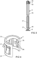
- FIG. 3 shows the bearing pin 5 of the pivot bearing FIG. 1
- the securing element 7 is connected in the vicinity of the free end of the bearing pin 5 arranged constriction 16 by means of a latching connection 19.
- the bearing pin 5 with the securing element 7 in a fork leg 3 from FIG. 2 inserted until the securing element 7 comes against the stop 10 and the locking connection 18 between the securing element 7 and the one fork leg 3 is generated.
- the bearing pin 5 is pushed through the entire pivot bearing until the securing element 7 is locked in the arranged close to the bolt head 6 constriction 15.
- the resilient clamping device 14 of the tubular sleeve 12 automatically enters the central constriction 13 of the bearing pin 5. Because the two fork legs 3, 4 are the same, the bearing pin can be inserted for mounting from each side into the bearing fork part. Further shows FIG. 3 in that the bearing pin 5 on the bolt head 6 and in a bolt shank 20 has respective flattened portions 21, 22 and is therefore out of round. In the FIG. 3 illustrated connection of the bearing pin 5 and the securing element 7 forms a preassembled unit, which is inserted for mounting in the other components of the pivot bearing from any side. By correspondingly flattened opposing components of the tube sleeve 12 and the bearing fork part 1 can prevent rotation of the bearing pin 5 during operation of the pivot bearing.
- FIG. 4 shows the fuse element 7 enlarged in a perspective view.
- the securing element 7 has two partial ring pieces 23, 24, which are connected to one another via webs 25.
- the webs 25 are bent inwardly in the middle to form ramps 26 which slide during assembly over the bolt shank 20 of the bearing pin 5 and with the two constrictions 15, 16 at the ends of the bearing pin 5, the snap-in connections 17, 19 described.
- a tongue 27 is angled radially outwardly from the partial ring piece 23, 24, which produces a part of the latching connection 18 in the receptacle 8 of a fork leg 3 in the mounted state.
Landscapes
- Engineering & Computer Science (AREA)
- Mechanical Engineering (AREA)
- Pivots And Pivotal Connections (AREA)
Abstract
Description
- Die Erfindung betrifft ein Drehlager, insbesondere eines Drehbeschlags oder Dreh-/Kipp-Beschlags eines Fensters, einer Fenstertür oder dergleichen, mit einem Gabelschenkel aufweisenden Lagergabelteil, mit einem zwischen die Gabelschenkel einsetzbaren Lageraugenteil, mit einem Lagerbolzen zur Lagerung des Lageraugenteils an den Gabelschenkel und mit einem Sicherungselement zur axialen Sicherung des Lagerbolzens an einem der Gabelschenkel, wobei das Sicherungselement in Einschnürungen des Lagerbolzens durch eine Rastverbindung gehalten ist. Weiterhin betrifft die Erfindung ein Verfahren zur Montage eines solchen Drehlagers.
- Bei solchen Drehlagern ist es erforderlich, dass der Lagerbolzen als sicherheitsrelevantes Bauteil besonders gegen ein Herausfallen gesichert ist. Insbesondere bei Scherenlagern von Dreh-/Kipp-Beschlägen wird aus Platzgründen der Lagerbolzen meist von unten in das Lagergabelteil und das Lageraugenteil eingeschoben.
- Ein solches Drehlager ist beispielsweise aus der
EP 2 476 844 A2 bekannt. Bei diesem Drehlager ist das Sicherungselement gabelförmig gestaltet und umgreift mit zwei Rastarmen einander gegenüberliegende Seiten des Lagerbolzens. Das Sicherungselement wird quer zur Lagerachse in einem der Gabelschenkel montiert. Die federnden Rastarme ermöglichen eine Verschiebung der Lagerachse in Achsrichtung. Nachteilig bei dem Drehlager ist, dass die Montage des Sicherungselementes und der Lagerachse aufwändig ist. - Aus der
EP 2 085 549 A1 ist ein Drehlager bekannt geworden, bei dem ein Sicherungselement von oben und der Lagerbolzen von unten montiert wird. Die Montage des Drehlagers gestaltet sich hierdurch sehr aufwändig, weiterhin ist die sichere Verrastung des Lagerbolzens in dem Sicherungselement nur sehr schwer zu überwachen. - Der Erfindung liegt das Problem zugrunde, ein Drehlager der eingangs genannten Art so weiter zu bilden, dass es einen sicheren Halt des Lagerbolzens gewährleistet und besonders einfach zu montieren ist. Weiterhin soll eine sichere Montage des Drehlagers geschaffen werden.
- Das erstgenannte Problem wird erfindungsgemäß dadurch gelöst, dass das Sicherungselement durch eine zweite Rastverbindung in einem der Gabelschenkel gehalten ist und dass der Gabelschenkel einen Anschlag zur Abstützung des Sicherungselementes hat.
- Durch diese Gestaltung ist sichergestellt, dass das Sicherungselement in dem Lagergabelteil durch den Anschlag zuverlässig positioniert ist. Weiterhin stellt der Anschlag sicher, dass das Sicherungselement in dem Gabelschenkel verbleibt, in den es zuerst eingeführt wurde. Damit kann das Sicherungselement zusammen mit dem Lagerbolzen in einen der Gabelschenkel eingeführt werden bis es an dem Anschlag abgestützt und verrastet. Anschließend wird der Lagerbolzen in den zweiten Gabelschenkel geschoben bis er in dem Sicherungselement verrastet. Damit lässt sich das erfindungsgemäße Drehlager besonders kostengünstig fertigen. Die zweite Rastverbindung zur Halterung des Sicherungselementes in einem der Gabelschenkel kann auch durch ein Verklemmen oder Verhaken erzeugt sein.
- Die beiden Rastverbindungen gestalten sich gemäß einer anderen vorteilhaften Weiterbildung der Erfindung konstruktiv besonders einfach, wenn das Sicherungselement hülsenförmig, den Lagerbolzen umschließend gestaltet ist und ein nach innen weisendes Rastelement und ein nach außen weisendes Rastelement hat.
- Die Fertigung des Sicherungselementes gestaltet sich gemäß einer anderen vorteilhaften Weiterbildung der Erfindung besonders kostengünstig, wenn das Sicherungselement aus Federstahl gefertigt ist und die Rastelemente als abgewinkelter Steg oder Zunge ausgebildet sind.
- Die Montage des Sicherungselementes in dem Lagerauge gestaltet sich gemäß einer anderen vorteilhaften Weiterbildung der Erfindung besonders einfach, wenn eine Rastverbindung des Sicherungselementes mit einem freien Ende des Lagerbolzens eine größere Haltekraft aufweist, als zur Erzeugung der Rastverbindung in dem Gabelschenkel erforderlich ist.
Durch diese Gestaltung kann das Sicherungselement zunächst auf dem Lagerbolzen montiert und anschließend zusammen mit dem Lagerbolzen in den Gabelschenkel eingeführt werden. Dabei wird das Sicherungselement zunächst auf dem Lagerbolzen gehalten. Anschließend lässt sich das Sicherungselement in einem der Gabelschenkel verrasten und der Lagerbolzen durch die übrigen Bauteile des Drehlagers schieben. - Eine unerwünschte Verdrehung des Lagerbolzens lässt sich gemäß einer anderen vorteilhaften Weiterbildung der Erfindung einfach vermeiden, wenn der Lagerbolzen und ein gegenüberstehendes Bauteil in einander gegenüberstehenden Abschnitten unrund gestaltet sind. Vorzugsweise hat der Lagerbolzen zur Erzeugung des unrunden Abschnitts eine Abflachung.
- Die unrunde Gestaltung des Sicherungselementes lässt sich gemäß einer anderen vorteilhaften Weiterbildung der Erfindung einfach herstellen, wenn das Sicherungselement einseitig offen gestaltet ist.
- Zur Vereinfachung der Montage des Sicherungselementes trägt es gemäß einer anderen vorteilhaften Weiterbildung der Erfindung bei, wenn die Rastelemente Rampen aufweisen.
- Das Sicherungselement gestaltet sich gemäß einer anderen vorteilhaften Weiterbildung der Erfindung besonders kostengünstig, wenn das Sicherungselement zwei Teilringstücke aufweist, wenn die Teilringstücke mit dem Steg verbunden sind, wenn der Steg zur Bildung der Rampen mittig nach innen abgeknickt ist und wenn die Zunge nach außen weist.
- Der Lagerbolzen lässt sich gemäß einer anderen vorteilhaften Weiterbildung der Erfindung zusammen mit dem Sicherungselement wahlweise von der einen oder der anderen Seite montieren, wenn jeder der Gabelschenkel eine Aufnahme für das Sicherungselement hat.
- Die Ausrichtung des Lageraugenteils gegenüber dem Lagergabelteil gestaltet sich gemäß einer anderen vorteilhaften Weiterbildung der Erfindung besonders einfach, wenn der Lagerbolzen eine zentrische Einschnürung zur Halterung einer in dem Lageraugenteil angeordneten Rohrhülse hat.
- Zur weiteren konstruktiven Vereinfachung des Drehlagers trägt es gemäß einer anderen vorteilhaften Weiterbildung der Erfindung bei, wenn der Lagerbolzen an seinen Enden jeweils eine Einschnürung zur Erzeugung der Rastverbindung mit dem Sicherungselement hat.
- Das zweit genannte Problem, nämlich die Schaffung eines besonders sicheren Verfahrens zur Montage eines solchen Drehlagers wird erfindungsgemäß dadurch gelöst, dass in einem ersten Schritt das Sicherungselement in einer ersten Einschnürung des Lagerbolzens verrastet wird, in einem zweiten Schritt der Lagerbolzen mit dem Sicherungselement in einen der Gabelschenkel eingeführt wird, bis das Sicherungselement in dem Gabelschenkel an einen Anschlag anstößt und verrastet ist und in einem dritten Schritt der Lagerbolzen durch das Lageraugenteil in den anderen Gabelschenkel geschoben wird bis das Sicherungselement in einer weiteren Einschnürung des Lagerbolzens verrastet.
- Durch den Anschlag ist sichergestellt, wenn das Sicherungselement zuverlässig in dem ersten Gabelschenkel verrastet ist, wenn der Lagerbolzen in das Lageraugenteil eingeschoben wird. Wenn der Lagerbolzen anschließend vollständig in das Lagergabelteil eingeschoben und in dem Sicherungselement fühlbar verrastet ist, ist weiterhin sichergestellt, dass der Lagerbolzen in seiner vorgesehenen Lage gehalten ist. Damit werden Fehler bei der Montage des Lagerbolzens zuverlässig vermieden. Weiterhin gestaltet sich die Montage des Drehlagers besonders einfach, weil der Lagerbolzen mit dem Sicherungselement als vormontierbare Einheit in das Lagergabelteil eingeführt werden kann.
- Die Erfindung lässt zahlreiche Ausführungsformen zu. Zur weiteren Verdeutlichung ihres Grundprinzips ist eine davon in der Zeichnung dargestellt und wird nachfolgend beschrieben. Diese zeigt in
- Fig. 1
- ein Drehlager im montierten Zustand,
- Fig. 2
- einen Längsschnitt durch das Drehlager aus
Figur 1 , - Fig. 3
- ein Lagerbolzen des Drehlagers aus
Figur 1 vor der Montage, - Fig. 4
- stark vergrößert ein Sicherungselement für das Drehlager in einer perspektivischen Darstellung.
-
Figur 1 zeigt ein Drehlager eines Dreh-/Kipp-Beschlages eines Fensters. Das Drehlager hat ein Lagergabelteil 1, welches zur Verschraubung beispielsweise an einem Rahmen des Fensters vorgesehen ist und ein Lageraugenteil 2, welches beispielsweise zur Verbindung mit einer Ausstellschere des Dreh-/Kipp-Beschlags vorgesehen ist. Das Lagergabelteil 1 hat zwei auf Abstand zueinander angeordnete Gabelschenkel 3,4. Das Lageraugenteil 2 ist zwischen die Gabelschenkel 3, 4 eingesetzt. Ein Lagerbolzen 5 durchdringt die beiden Gabelschenkel 3, 4 und das Lageraugenteil 2. Mit einem Bolzenkopf 6 stützt sich der Lagerbolzen 5 an einem der Gabelschenkel 3 ab. -
Figur 2 zeigt einen Längsschnitt durch das Drehlager ausFigur 1 . Der Lagerbolzen 5 ist von einem Sicherungselement 7 in einem der Gabelschenkel 3 verrastet. Das Sicherungselement 7 ist in einer Aufnahme 8 des einen Gabelschenkels 3 angeordnet und stützt sich an einem Anschlag 10 ab. Die beiden Gabelschenkel 3, 4 sind gleich aufgebaut, so dass der andere Gabelschenkel 4 ebenfalls eine Aufnahme 9 mit einem Anschlag 11 hat. Weiterhin zeigtFigur 2 , dass das Lageraugenteil 2 eine Rohrhülse 12 hat, in der der Lagerbolzen 5 angeordnet ist. Der Lagerbolzen 5 hat eine zentrische Einschnürung 13 für eine federelastische Klemmeinrichtung 14 der Rohrhülse 12. Rohrhülse 12 und Lagerbolzen 5 sind unverdrehbar miteinander verbunden und in axialer Richtung über die Klemmeinrichtung 14 gehalten. Der Lagerbolzen 5 ist ebenfalls unverdrehbar in dem Lagergabelteil 1 gehalten, so dass das Lageraugenteil 2 bei einer Verdrehung gegenüber dem Lagergabelteil 1 über die Rohrhülse 12 gleitet. Der Lagerbolzen 5 hat zwei Einschnürungen 15, 16 an seinen Enden. Das Sicherungselement 7 hat eine erste Rastverbindung 17 in der nahe am Bolzenkopf 6 angeordneten Einschnürung 15 und eine zweite Rastverbindung 18 in der Aufnahme 8 des einen Gabelschenkels 3. -
Figur 3 zeigt den Lagerbolzen 5 des Drehlagers ausFigur 1 mit dem Sicherungselement 7 vor der Montage im Lagergabelteil 1. Hierbei ist zu erkennen, dass das Sicherungselement 7 in der nahe am freien Ende des Lagerbolzens 5 angeordneten Einschnürung 16 mittels einer Rastverbindung 19 verbunden ist. Zur Montage wird der Lagerbolzen 5 mit dem Sicherungselement 7 in den einen Gabelschenkel 3 ausFigur 2 eingeschoben, bis das Sicherungselement 7 gegen den Anschlag 10 gelangt und die Rastverbindung 18 zwischen dem Sicherungselement 7 und dem einen Gabelschenkel 3 erzeugt ist. Anschließend wird der Lagerbolzen 5 durch das gesamte Drehlager geschoben bis das Sicherungselement 7 in der nahe am Bolzenkopf 6 angeordneten Einschnürung 15 verrastet. Dabei gelangt die federelastische Klemmeinrichtung 14 der Rohrhülse 12 automatisch in die zentrische Einschnürung 13 des Lagerbolzens 5. Weil die beiden Gabelschenkel 3, 4 gleich aufgebaut sind, kann der Lagerbolzen zur Montage von jeder Seite her in das Lagergabelteil eingeschoben werden. Weiterhin zeigtFigur 3 , dass der Lagerbolzen 5 am Bolzenkopf 6 und in einem Bolzenschaft 20 jeweils Abflachungen 21, 22 aufweist und damit unrund gestaltet ist. Die inFigur 3 dargestellte Verbindung des Lagerbolzens 5 und des Sicherungselementes 7 bildet eine vormontierte Einheit, welche zur Montage in die übrigen Bauteile des Drehlagers von einer beliebigen Seite her eingeschoben wird. Durch entsprechend abgeflachte gegenüberstehende Bauteile der Rohrhülse 12 und des Lagergabelteils 1 lässt sich eine Verdrehung des Lagerbolzens 5 im Betrieb des Drehlagers verhindern. -
Figur 4 zeigt das Sicherungselement 7 vergrößert in einer perspektivischen Darstellung. Das Sicherungselement 7 hat zwei Teilringstücke 23, 24, welche über Stege 25 miteinander verbunden sind. Die Stege 25 sind in der Mitte nach innen abgeknickt zur Bildung von Rampen 26, welchen bei der Montage über den Bolzenschaft 20 des Lagerbolzens 5 gleiten und mit den beiden Einschnürungen 15, 16 an den Enden des Lagerbolzens 5 die beschriebenen Rastverbindungen 17, 19 bilden. Weiterhin ist von dem Teilringstück 23, 24 eine Zunge 27 radial nach außen abgewinkelt, welche im montierten Zustand einen Teil der Rastverbindung 18 in der Aufnahme 8 des einen Gabelschenkels 3 erzeugt.
Claims (12)
- Drehlager, insbesondere eines Drehbeschlags oder Dreh-/Kipp- Beschlags eines Fensters, einer Fenstertür oder dergleichen, mit einem Gabelschenkel (3, 4) aufweisenden Lagergabelteil (1), mit einem zwischen die Gabelschenkel (3, 4) einsetzbaren Lageraugenteil (2), mit einem Lagerbolzen (5) zur Lagerung des Lageraugenteils (2) an den Gabelschenkel (3, 4) und mit einem Sicherungselement (7) zur axialen Sicherung des Lagerbolzens (5) an einem der Gabelschenkel (3, 4), wobei das Sicherungselement (7) in Einschnürungen (15, 16) des Lagerbolzens (5) durch eine Rastverbindung (17) gehalten ist, dadurch gekennzeichnet, dass das Sicherungselement (7) durch eine zweite Rastverbindung (18) in einem der Gabelschenkel (3, 4) gehalten ist und dass der Gabelschenkel (3) einen Anschlag (10, 11) zur Abstützung des Sicherungselementes (7) hat.
- Drehlager nach Anspruch 1, dadurch gekennzeichnet, dass das Sicherungselement (7) hülsenförmig, den Lagerbolzen (5) umschließend gestaltet ist und ein nach innen weisendes Rastelement und ein nach außen weisendes Rastelement hat.
- Drehlager nach Anspruch 2, dadurch gekennzeichnet, dass das Sicherungselement (7) aus Federstahl gefertigt ist und die Rastelemente als abgewinkelter Steg (25) oder Zunge (27) ausgebildet sind.
- Drehlager nach einem der vorhergehenden Ansprüche, dadurch gekennzeichnet, dass eine Rastverbindung (19) des Sicherungselementes (7) mit einem freien Ende des Lagerbolzens (5) eine größere Haltekraft aufweist, als zur Erzeugung der Rastverbindung (18) in dem Gabelschenkel (3, 4) erforderlich ist.
- Drehlager nach einem der vorhergehenden Ansprüche, dadurch gekennzeichnet, dass der Lagerbolzen (5) und ein gegenüberstehendes Bauteil in einander gegenüberstehenden Abschnitten unrund gestaltet sind.
- Drehlager nach einem der vorhergehenden Ansprüche, dadurch gekennzeichnet, dass das Sicherungselement (7) einseitig offen gestaltet ist.
- Drehlager nach einem der vorhergehenden Ansprüche, dadurch gekennzeichnet, dass die Rastelemente Rampen (26) aufweisen.
- Drehlager nach Anspruch 3 und 7, dadurch gekennzeichnet, dass das Sicherungselement (7) zwei Teilringstücke (23, 24) aufweist, dass die Teilringstücke (23, 24) mit dem Steg (25) verbunden sind, dass der Steg (25) zur Bildung der Rampen (26) mittig nach innen abgeknickt ist und dass die Zunge (27) nach außen weist.
- Drehlager nach einem der vorhergehenden Ansprüche, dadurch gekennzeichnet, dass jeder der Gabelschenkel (3, 4) eine Aufnahme (8, 9) für das Sicherungselement (7) hat.
- Drehlager nach einem der vorhergehenden Ansprüche, dadurch gekennzeichnet, dass der Lagerbolzen (5) eine zentrische Einschnürung (13) zur Halterung einer in dem Lageraugenteil (2) angeordneten Rohrhülse (12) hat.
- Drehlager nach einem der vorhergehenden Ansprüche, dadurch gekennzeichnet, dass der Lagerbolzen (5) an seinen Enden jeweils eine Einschnürung (15, 16) zur Erzeugung der Rastverbindung (17, 19) mit dem Sicherungselement (7) hat.
- Verfahren zur Montage eines Drehlagers nach einem der vorhergehenden Ansprüche, dadurch gekennzeichnet, dass in einem ersten Schritt das Sicherungselement (7) in einer ersten Einschnürung (16) des Lagerbolzens (5) verrastet wird, in einem zweiten Schritt der Lagerbolzen (5) mit dem Sicherungselement (7) in einen der Gabelschenkel (3, 4) eingeführt wird, bis das Sicherungselement (7) in dem Gabelschenkel (3, 4) an einen Anschlag (10, 11) anstößt und verrastet ist und in einem dritten Schritt der Lagerbolzen (5) durch das Lageraugenteil (2) in den anderen Gabelschenkel (4, 3) geschoben wird bis das Sicherungselement (7) in einer weiteren Einschnürung (15) des Lagerbolzens (5) verrastet.
Priority Applications (1)
| Application Number | Priority Date | Filing Date | Title |
|---|---|---|---|
| PL18185141T PL3447224T3 (pl) | 2017-08-24 | 2018-07-24 | Łożysko obrotowe i sposób montażu takiego łożyska obrotowego |
Applications Claiming Priority (1)
| Application Number | Priority Date | Filing Date | Title |
|---|---|---|---|
| DE102017214864.0A DE102017214864A1 (de) | 2017-08-24 | 2017-08-24 | Drehlager und Verfahren zur Montage eines solchen Drehlagers |
Publications (2)
| Publication Number | Publication Date |
|---|---|
| EP3447224A1 true EP3447224A1 (de) | 2019-02-27 |
| EP3447224B1 EP3447224B1 (de) | 2020-09-02 |
Family
ID=63041853
Family Applications (1)
| Application Number | Title | Priority Date | Filing Date |
|---|---|---|---|
| EP18185141.1A Active EP3447224B1 (de) | 2017-08-24 | 2018-07-24 | Drehlager und verfahren zur montage eines solchen drehlagers |
Country Status (4)
| Country | Link |
|---|---|
| EP (1) | EP3447224B1 (de) |
| DE (1) | DE102017214864A1 (de) |
| ES (1) | ES2836176T3 (de) |
| PL (1) | PL3447224T3 (de) |
Cited By (1)
| Publication number | Priority date | Publication date | Assignee | Title |
|---|---|---|---|---|
| CN111677389A (zh) * | 2019-03-11 | 2020-09-18 | 通用汽车环球科技运作有限责任公司 | 锁定铰链组件 |
Citations (5)
| Publication number | Priority date | Publication date | Assignee | Title |
|---|---|---|---|---|
| EP0823525A1 (de) * | 1996-08-08 | 1998-02-11 | ED. SCHARWÄCHTER GmbH & Co. KG | Trennbares Kraftwagentürscharnier |
| EP1319785A2 (de) * | 2001-12-13 | 2003-06-18 | van Parys, Remi Emiel | Scharnier und Scharnierteil dafür |
| EP2085549A1 (de) | 2008-01-31 | 2009-08-05 | SAVIO S.p.A. | Ein Scharnier für Türen oder Fenster |
| EP2476844A2 (de) | 2011-01-18 | 2012-07-18 | Aug. Winkhaus GmbH & Co. KG | Drehlager |
| EP2636831A1 (de) * | 2012-03-07 | 2013-09-11 | Roto Frank AG | Lager für Flügel von Fenstern, Türen oder dergleichen mit einem Federelement |
-
2017
- 2017-08-24 DE DE102017214864.0A patent/DE102017214864A1/de not_active Withdrawn
-
2018
- 2018-07-24 PL PL18185141T patent/PL3447224T3/pl unknown
- 2018-07-24 ES ES18185141T patent/ES2836176T3/es active Active
- 2018-07-24 EP EP18185141.1A patent/EP3447224B1/de active Active
Patent Citations (5)
| Publication number | Priority date | Publication date | Assignee | Title |
|---|---|---|---|---|
| EP0823525A1 (de) * | 1996-08-08 | 1998-02-11 | ED. SCHARWÄCHTER GmbH & Co. KG | Trennbares Kraftwagentürscharnier |
| EP1319785A2 (de) * | 2001-12-13 | 2003-06-18 | van Parys, Remi Emiel | Scharnier und Scharnierteil dafür |
| EP2085549A1 (de) | 2008-01-31 | 2009-08-05 | SAVIO S.p.A. | Ein Scharnier für Türen oder Fenster |
| EP2476844A2 (de) | 2011-01-18 | 2012-07-18 | Aug. Winkhaus GmbH & Co. KG | Drehlager |
| EP2636831A1 (de) * | 2012-03-07 | 2013-09-11 | Roto Frank AG | Lager für Flügel von Fenstern, Türen oder dergleichen mit einem Federelement |
Cited By (1)
| Publication number | Priority date | Publication date | Assignee | Title |
|---|---|---|---|---|
| CN111677389A (zh) * | 2019-03-11 | 2020-09-18 | 通用汽车环球科技运作有限责任公司 | 锁定铰链组件 |
Also Published As
| Publication number | Publication date |
|---|---|
| EP3447224B1 (de) | 2020-09-02 |
| DE102017214864A1 (de) | 2019-02-28 |
| ES2836176T3 (es) | 2021-06-24 |
| PL3447224T3 (pl) | 2021-01-25 |
Similar Documents
| Publication | Publication Date | Title |
|---|---|---|
| EP1041298B1 (de) | Montageeelement, insbesondere für den Möbelbau | |
| EP2443003B1 (de) | Verbindungsbaugruppe | |
| DE10313170B3 (de) | Steckbolzen mit druckknopfbetätigter Axialsicherung und freier Lagerung | |
| DE102013216716A1 (de) | Toleranzausgleichsvorrichtung | |
| DE102017127750A1 (de) | Drahtgewindeeinsatz | |
| DE102014101119A1 (de) | Befestigungsclip | |
| WO2016193011A1 (de) | Verriegelungssystem für einen ladestecker | |
| EP3676132B1 (de) | Federelement zur befestigung eines gassackmoduls an einem fahrzeuglenkrad sowie lenkradbaugruppe mit einem solchen federelement | |
| EP3581811A1 (de) | System zur befestigung einer ersten komponente an einer zweiten komponente | |
| DE10302984B3 (de) | Säuleneinheit | |
| EP3809010A1 (de) | Reibungsdämpfer | |
| EP3447224A1 (de) | Drehlager und verfahren zur montage eines solchen drehlagers | |
| EP3119641B1 (de) | Verbindungsanordnung für ein gestänge eines fahrzeugsitzes und fahrzeugsitz | |
| EP2867569B1 (de) | Steckverbinder, insbesondere für medienführende leitungen | |
| EP2191174B1 (de) | Gleitlageranordnung für ein bewegbares schaltelement in einer schaltvorrichtung sowie schaltvorrichtung mit der gleitlageranordnung | |
| EP3115625B1 (de) | Zug-druck-stange mit verbindungsbolzen | |
| EP4202235A1 (de) | Befestigungsanordnung | |
| DE19904713C1 (de) | Vorrichtung zur axialen Festlegung eines Bolzens | |
| DE102018104360A1 (de) | Befestigungssystem zum Sichern von Bauteilen | |
| DE102008056460B4 (de) | Federbolzenanordnung für teleskopierbare Zeltstangen | |
| DE102005027281B4 (de) | Verbindungsvorrichtung zwischen einem länglichen Bauteil und einer Gewindestange | |
| EP3636863B1 (de) | Gelenksicherung | |
| DE202017104066U1 (de) | Rastbolzen für ein Stativ | |
| DE102006035191A1 (de) | Medizinische Vorrichtung | |
| DE102023133982A1 (de) | Befestigungsanordnung, Bauteil mit der Befestigungsanordnung, dazugehörige Verbindungsstruktur sowie Herstellungs- und Verbindungsverfahren |
Legal Events
| Date | Code | Title | Description |
|---|---|---|---|
| PUAI | Public reference made under article 153(3) epc to a published international application that has entered the european phase |
Free format text: ORIGINAL CODE: 0009012 |
|
| STAA | Information on the status of an ep patent application or granted ep patent |
Free format text: STATUS: THE APPLICATION HAS BEEN PUBLISHED |
|
| AK | Designated contracting states |
Kind code of ref document: A1 Designated state(s): AL AT BE BG CH CY CZ DE DK EE ES FI FR GB GR HR HU IE IS IT LI LT LU LV MC MK MT NL NO PL PT RO RS SE SI SK SM TR |
|
| AX | Request for extension of the european patent |
Extension state: BA ME |
|
| STAA | Information on the status of an ep patent application or granted ep patent |
Free format text: STATUS: REQUEST FOR EXAMINATION WAS MADE |
|
| 17P | Request for examination filed |
Effective date: 20190730 |
|
| RBV | Designated contracting states (corrected) |
Designated state(s): AL AT BE BG CH CY CZ DE DK EE ES FI FR GB GR HR HU IE IS IT LI LT LU LV MC MK MT NL NO PL PT RO RS SE SI SK SM TR |
|
| GRAP | Despatch of communication of intention to grant a patent |
Free format text: ORIGINAL CODE: EPIDOSNIGR1 |
|
| STAA | Information on the status of an ep patent application or granted ep patent |
Free format text: STATUS: GRANT OF PATENT IS INTENDED |
|
| RIC1 | Information provided on ipc code assigned before grant |
Ipc: E05D 5/12 20060101AFI20200318BHEP Ipc: E05D 7/10 20060101ALI20200318BHEP |
|
| INTG | Intention to grant announced |
Effective date: 20200407 |
|
| GRAS | Grant fee paid |
Free format text: ORIGINAL CODE: EPIDOSNIGR3 |
|
| GRAA | (expected) grant |
Free format text: ORIGINAL CODE: 0009210 |
|
| STAA | Information on the status of an ep patent application or granted ep patent |
Free format text: STATUS: THE PATENT HAS BEEN GRANTED |
|
| AK | Designated contracting states |
Kind code of ref document: B1 Designated state(s): AL AT BE BG CH CY CZ DE DK EE ES FI FR GB GR HR HU IE IS IT LI LT LU LV MC MK MT NL NO PL PT RO RS SE SI SK SM TR |
|
| REG | Reference to a national code |
Ref country code: GB Ref legal event code: FG4D Free format text: NOT ENGLISH |
|
| REG | Reference to a national code |
Ref country code: AT Ref legal event code: REF Ref document number: 1308982 Country of ref document: AT Kind code of ref document: T Effective date: 20200915 Ref country code: CH Ref legal event code: EP |
|
| REG | Reference to a national code |
Ref country code: DE Ref legal event code: R096 Ref document number: 502018002330 Country of ref document: DE |
|
| REG | Reference to a national code |
Ref country code: IE Ref legal event code: FG4D Free format text: LANGUAGE OF EP DOCUMENT: GERMAN |
|
| REG | Reference to a national code |
Ref country code: LT Ref legal event code: MG4D |
|
| PG25 | Lapsed in a contracting state [announced via postgrant information from national office to epo] |
Ref country code: FI Free format text: LAPSE BECAUSE OF FAILURE TO SUBMIT A TRANSLATION OF THE DESCRIPTION OR TO PAY THE FEE WITHIN THE PRESCRIBED TIME-LIMIT Effective date: 20200902 Ref country code: HR Free format text: LAPSE BECAUSE OF FAILURE TO SUBMIT A TRANSLATION OF THE DESCRIPTION OR TO PAY THE FEE WITHIN THE PRESCRIBED TIME-LIMIT Effective date: 20200902 Ref country code: LT Free format text: LAPSE BECAUSE OF FAILURE TO SUBMIT A TRANSLATION OF THE DESCRIPTION OR TO PAY THE FEE WITHIN THE PRESCRIBED TIME-LIMIT Effective date: 20200902 Ref country code: BG Free format text: LAPSE BECAUSE OF FAILURE TO SUBMIT A TRANSLATION OF THE DESCRIPTION OR TO PAY THE FEE WITHIN THE PRESCRIBED TIME-LIMIT Effective date: 20201202 Ref country code: GR Free format text: LAPSE BECAUSE OF FAILURE TO SUBMIT A TRANSLATION OF THE DESCRIPTION OR TO PAY THE FEE WITHIN THE PRESCRIBED TIME-LIMIT Effective date: 20201203 Ref country code: NO Free format text: LAPSE BECAUSE OF FAILURE TO SUBMIT A TRANSLATION OF THE DESCRIPTION OR TO PAY THE FEE WITHIN THE PRESCRIBED TIME-LIMIT Effective date: 20201202 Ref country code: SE Free format text: LAPSE BECAUSE OF FAILURE TO SUBMIT A TRANSLATION OF THE DESCRIPTION OR TO PAY THE FEE WITHIN THE PRESCRIBED TIME-LIMIT Effective date: 20200902 |
|
| REG | Reference to a national code |
Ref country code: NL Ref legal event code: MP Effective date: 20200902 |
|
| PG25 | Lapsed in a contracting state [announced via postgrant information from national office to epo] |
Ref country code: LV Free format text: LAPSE BECAUSE OF FAILURE TO SUBMIT A TRANSLATION OF THE DESCRIPTION OR TO PAY THE FEE WITHIN THE PRESCRIBED TIME-LIMIT Effective date: 20200902 Ref country code: RS Free format text: LAPSE BECAUSE OF FAILURE TO SUBMIT A TRANSLATION OF THE DESCRIPTION OR TO PAY THE FEE WITHIN THE PRESCRIBED TIME-LIMIT Effective date: 20200902 |
|
| PG25 | Lapsed in a contracting state [announced via postgrant information from national office to epo] |
Ref country code: EE Free format text: LAPSE BECAUSE OF FAILURE TO SUBMIT A TRANSLATION OF THE DESCRIPTION OR TO PAY THE FEE WITHIN THE PRESCRIBED TIME-LIMIT Effective date: 20200902 Ref country code: RO Free format text: LAPSE BECAUSE OF FAILURE TO SUBMIT A TRANSLATION OF THE DESCRIPTION OR TO PAY THE FEE WITHIN THE PRESCRIBED TIME-LIMIT Effective date: 20200902 Ref country code: PT Free format text: LAPSE BECAUSE OF FAILURE TO SUBMIT A TRANSLATION OF THE DESCRIPTION OR TO PAY THE FEE WITHIN THE PRESCRIBED TIME-LIMIT Effective date: 20210104 Ref country code: CZ Free format text: LAPSE BECAUSE OF FAILURE TO SUBMIT A TRANSLATION OF THE DESCRIPTION OR TO PAY THE FEE WITHIN THE PRESCRIBED TIME-LIMIT Effective date: 20200902 Ref country code: SM Free format text: LAPSE BECAUSE OF FAILURE TO SUBMIT A TRANSLATION OF THE DESCRIPTION OR TO PAY THE FEE WITHIN THE PRESCRIBED TIME-LIMIT Effective date: 20200902 |
|
| PG25 | Lapsed in a contracting state [announced via postgrant information from national office to epo] |
Ref country code: AL Free format text: LAPSE BECAUSE OF FAILURE TO SUBMIT A TRANSLATION OF THE DESCRIPTION OR TO PAY THE FEE WITHIN THE PRESCRIBED TIME-LIMIT Effective date: 20200902 Ref country code: IS Free format text: LAPSE BECAUSE OF FAILURE TO SUBMIT A TRANSLATION OF THE DESCRIPTION OR TO PAY THE FEE WITHIN THE PRESCRIBED TIME-LIMIT Effective date: 20210102 |
|
| REG | Reference to a national code |
Ref country code: DE Ref legal event code: R097 Ref document number: 502018002330 Country of ref document: DE |
|
| REG | Reference to a national code |
Ref country code: ES Ref legal event code: FG2A Ref document number: 2836176 Country of ref document: ES Kind code of ref document: T3 Effective date: 20210624 |
|
| PG25 | Lapsed in a contracting state [announced via postgrant information from national office to epo] |
Ref country code: SK Free format text: LAPSE BECAUSE OF FAILURE TO SUBMIT A TRANSLATION OF THE DESCRIPTION OR TO PAY THE FEE WITHIN THE PRESCRIBED TIME-LIMIT Effective date: 20200902 |
|
| PLBE | No opposition filed within time limit |
Free format text: ORIGINAL CODE: 0009261 |
|
| STAA | Information on the status of an ep patent application or granted ep patent |
Free format text: STATUS: NO OPPOSITION FILED WITHIN TIME LIMIT |
|
| 26N | No opposition filed |
Effective date: 20210603 |
|
| PG25 | Lapsed in a contracting state [announced via postgrant information from national office to epo] |
Ref country code: SI Free format text: LAPSE BECAUSE OF FAILURE TO SUBMIT A TRANSLATION OF THE DESCRIPTION OR TO PAY THE FEE WITHIN THE PRESCRIBED TIME-LIMIT Effective date: 20200902 Ref country code: DK Free format text: LAPSE BECAUSE OF FAILURE TO SUBMIT A TRANSLATION OF THE DESCRIPTION OR TO PAY THE FEE WITHIN THE PRESCRIBED TIME-LIMIT Effective date: 20200902 |
|
| REG | Reference to a national code |
Ref country code: CH Ref legal event code: PL |
|
| PG25 | Lapsed in a contracting state [announced via postgrant information from national office to epo] |
Ref country code: MC Free format text: LAPSE BECAUSE OF FAILURE TO SUBMIT A TRANSLATION OF THE DESCRIPTION OR TO PAY THE FEE WITHIN THE PRESCRIBED TIME-LIMIT Effective date: 20200902 |
|
| PG25 | Lapsed in a contracting state [announced via postgrant information from national office to epo] |
Ref country code: LI Free format text: LAPSE BECAUSE OF NON-PAYMENT OF DUE FEES Effective date: 20210731 Ref country code: CH Free format text: LAPSE BECAUSE OF NON-PAYMENT OF DUE FEES Effective date: 20210731 |
|
| PG25 | Lapsed in a contracting state [announced via postgrant information from national office to epo] |
Ref country code: LU Free format text: LAPSE BECAUSE OF NON-PAYMENT OF DUE FEES Effective date: 20210724 |
|
| PG25 | Lapsed in a contracting state [announced via postgrant information from national office to epo] |
Ref country code: IE Free format text: LAPSE BECAUSE OF NON-PAYMENT OF DUE FEES Effective date: 20210724 |
|
| GBPC | Gb: european patent ceased through non-payment of renewal fee |
Effective date: 20220724 |
|
| PG25 | Lapsed in a contracting state [announced via postgrant information from national office to epo] |
Ref country code: GB Free format text: LAPSE BECAUSE OF NON-PAYMENT OF DUE FEES Effective date: 20220724 |
|
| P01 | Opt-out of the competence of the unified patent court (upc) registered |
Effective date: 20230516 |
|
| PG25 | Lapsed in a contracting state [announced via postgrant information from national office to epo] |
Ref country code: NL Free format text: LAPSE BECAUSE OF NON-PAYMENT OF DUE FEES Effective date: 20200923 Ref country code: CY Free format text: LAPSE BECAUSE OF FAILURE TO SUBMIT A TRANSLATION OF THE DESCRIPTION OR TO PAY THE FEE WITHIN THE PRESCRIBED TIME-LIMIT Effective date: 20200902 |
|
| PG25 | Lapsed in a contracting state [announced via postgrant information from national office to epo] |
Ref country code: HU Free format text: LAPSE BECAUSE OF FAILURE TO SUBMIT A TRANSLATION OF THE DESCRIPTION OR TO PAY THE FEE WITHIN THE PRESCRIBED TIME-LIMIT; INVALID AB INITIO Effective date: 20180724 |
|
| PG25 | Lapsed in a contracting state [announced via postgrant information from national office to epo] |
Ref country code: MK Free format text: LAPSE BECAUSE OF FAILURE TO SUBMIT A TRANSLATION OF THE DESCRIPTION OR TO PAY THE FEE WITHIN THE PRESCRIBED TIME-LIMIT Effective date: 20200902 |
|
| PG25 | Lapsed in a contracting state [announced via postgrant information from national office to epo] |
Ref country code: MT Free format text: LAPSE BECAUSE OF FAILURE TO SUBMIT A TRANSLATION OF THE DESCRIPTION OR TO PAY THE FEE WITHIN THE PRESCRIBED TIME-LIMIT Effective date: 20200902 |
|
| REG | Reference to a national code |
Ref country code: DE Ref legal event code: R081 Ref document number: 502018002330 Country of ref document: DE Owner name: AUG. WINKHAUS SE & CO. KG, DE Free format text: FORMER OWNER: AUG. WINKHAUS GMBH & CO. KG, 48291 TELGTE, DE Ref country code: DE Ref legal event code: R081 Ref document number: 502018002330 Country of ref document: DE Owner name: AUG. WINKHAUS SE, DE Free format text: FORMER OWNER: AUG. WINKHAUS GMBH & CO. KG, 48291 TELGTE, DE |
|
| REG | Reference to a national code |
Ref country code: DE Ref legal event code: R081 Ref document number: 502018002330 Country of ref document: DE Owner name: AUG. WINKHAUS SE, DE Free format text: FORMER OWNER: AUG. WINKHAUS SE & CO. KG, 48291 TELGTE, DE |
|
| PGFP | Annual fee paid to national office [announced via postgrant information from national office to epo] |
Ref country code: ES Payment date: 20250819 Year of fee payment: 8 |
|
| PGFP | Annual fee paid to national office [announced via postgrant information from national office to epo] |
Ref country code: DE Payment date: 20250722 Year of fee payment: 8 |
|
| PGFP | Annual fee paid to national office [announced via postgrant information from national office to epo] |
Ref country code: PL Payment date: 20250711 Year of fee payment: 8 Ref country code: IT Payment date: 20250731 Year of fee payment: 8 |
|
| PGFP | Annual fee paid to national office [announced via postgrant information from national office to epo] |
Ref country code: BE Payment date: 20250722 Year of fee payment: 8 |
|
| PGFP | Annual fee paid to national office [announced via postgrant information from national office to epo] |
Ref country code: FR Payment date: 20250723 Year of fee payment: 8 Ref country code: AT Payment date: 20250721 Year of fee payment: 8 |
|
| PG25 | Lapsed in a contracting state [announced via postgrant information from national office to epo] |
Ref country code: TR Free format text: LAPSE BECAUSE OF FAILURE TO SUBMIT A TRANSLATION OF THE DESCRIPTION OR TO PAY THE FEE WITHIN THE PRESCRIBED TIME-LIMIT Effective date: 20200902 |