EP3446832A1 - Inner surface finishing tool - Google Patents
Inner surface finishing tool Download PDFInfo
- Publication number
- EP3446832A1 EP3446832A1 EP18187350.6A EP18187350A EP3446832A1 EP 3446832 A1 EP3446832 A1 EP 3446832A1 EP 18187350 A EP18187350 A EP 18187350A EP 3446832 A1 EP3446832 A1 EP 3446832A1
- Authority
- EP
- European Patent Office
- Prior art keywords
- rollers
- mandrel
- frame
- peripheral surface
- tool
- Prior art date
- Legal status (The legal status is an assumption and is not a legal conclusion. Google has not performed a legal analysis and makes no representation as to the accuracy of the status listed.)
- Granted
Links
- 230000002093 peripheral effect Effects 0.000 claims abstract description 53
- 230000003247 decreasing effect Effects 0.000 claims description 9
- 238000003754 machining Methods 0.000 abstract description 22
- 230000006866 deterioration Effects 0.000 abstract description 6
- 239000000463 material Substances 0.000 abstract description 6
- 230000033001 locomotion Effects 0.000 description 9
- 238000000034 method Methods 0.000 description 8
- 230000003746 surface roughness Effects 0.000 description 6
- 238000009499 grossing Methods 0.000 description 3
- 238000009987 spinning Methods 0.000 description 3
- XEEYBQQBJWHFJM-UHFFFAOYSA-N Iron Chemical compound [Fe] XEEYBQQBJWHFJM-UHFFFAOYSA-N 0.000 description 2
- 229910052782 aluminium Inorganic materials 0.000 description 2
- XAGFODPZIPBFFR-UHFFFAOYSA-N aluminium Chemical compound [Al] XAGFODPZIPBFFR-UHFFFAOYSA-N 0.000 description 2
- 229910000851 Alloy steel Inorganic materials 0.000 description 1
- OKTJSMMVPCPJKN-UHFFFAOYSA-N Carbon Chemical compound [C] OKTJSMMVPCPJKN-UHFFFAOYSA-N 0.000 description 1
- RTAQQCXQSZGOHL-UHFFFAOYSA-N Titanium Chemical compound [Ti] RTAQQCXQSZGOHL-UHFFFAOYSA-N 0.000 description 1
- NRTOMJZYCJJWKI-UHFFFAOYSA-N Titanium nitride Chemical compound [Ti]#N NRTOMJZYCJJWKI-UHFFFAOYSA-N 0.000 description 1
- 230000004323 axial length Effects 0.000 description 1
- 230000005540 biological transmission Effects 0.000 description 1
- 229910052799 carbon Inorganic materials 0.000 description 1
- 238000000576 coating method Methods 0.000 description 1
- 230000007423 decrease Effects 0.000 description 1
- 238000007730 finishing process Methods 0.000 description 1
- 229910052742 iron Inorganic materials 0.000 description 1
- 229910052751 metal Inorganic materials 0.000 description 1
- 239000002184 metal Substances 0.000 description 1
- 238000003825 pressing Methods 0.000 description 1
- 230000001105 regulatory effect Effects 0.000 description 1
- 238000005096 rolling process Methods 0.000 description 1
- 239000004065 semiconductor Substances 0.000 description 1
- 239000000725 suspension Substances 0.000 description 1
- 238000007669 thermal treatment Methods 0.000 description 1
- 239000010936 titanium Substances 0.000 description 1
- 229910052719 titanium Inorganic materials 0.000 description 1
Images


Classifications
-
- B—PERFORMING OPERATIONS; TRANSPORTING
- B24—GRINDING; POLISHING
- B24B—MACHINES, DEVICES, OR PROCESSES FOR GRINDING OR POLISHING; DRESSING OR CONDITIONING OF ABRADING SURFACES; FEEDING OF GRINDING, POLISHING, OR LAPPING AGENTS
- B24B39/00—Burnishing machines or devices, i.e. requiring pressure members for compacting the surface zone; Accessories therefor
- B24B39/003—Burnishing machines or devices, i.e. requiring pressure members for compacting the surface zone; Accessories therefor the working tool being composed of a plurality of working rolls or balls
-
- B—PERFORMING OPERATIONS; TRANSPORTING
- B24—GRINDING; POLISHING
- B24B—MACHINES, DEVICES, OR PROCESSES FOR GRINDING OR POLISHING; DRESSING OR CONDITIONING OF ABRADING SURFACES; FEEDING OF GRINDING, POLISHING, OR LAPPING AGENTS
- B24B39/00—Burnishing machines or devices, i.e. requiring pressure members for compacting the surface zone; Accessories therefor
- B24B39/02—Burnishing machines or devices, i.e. requiring pressure members for compacting the surface zone; Accessories therefor designed for working internal surfaces of revolution
- B24B39/023—Burnishing machines or devices, i.e. requiring pressure members for compacting the surface zone; Accessories therefor designed for working internal surfaces of revolution the working tool being composed of a plurality of working rolls or balls
-
- B—PERFORMING OPERATIONS; TRANSPORTING
- B23—MACHINE TOOLS; METAL-WORKING NOT OTHERWISE PROVIDED FOR
- B23P—METAL-WORKING NOT OTHERWISE PROVIDED FOR; COMBINED OPERATIONS; UNIVERSAL MACHINE TOOLS
- B23P9/00—Treating or finishing surfaces mechanically, with or without calibrating, primarily to resist wear or impact, e.g. smoothing or roughening turbine blades or bearings; Features of such surfaces not otherwise provided for, their treatment being unspecified
- B23P9/02—Treating or finishing by applying pressure, e.g. knurling
-
- B—PERFORMING OPERATIONS; TRANSPORTING
- B23—MACHINE TOOLS; METAL-WORKING NOT OTHERWISE PROVIDED FOR
- B23P—METAL-WORKING NOT OTHERWISE PROVIDED FOR; COMBINED OPERATIONS; UNIVERSAL MACHINE TOOLS
- B23P9/00—Treating or finishing surfaces mechanically, with or without calibrating, primarily to resist wear or impact, e.g. smoothing or roughening turbine blades or bearings; Features of such surfaces not otherwise provided for, their treatment being unspecified
- B23P9/04—Treating or finishing by hammering or applying repeated pressure
-
- B—PERFORMING OPERATIONS; TRANSPORTING
- B24—GRINDING; POLISHING
- B24B—MACHINES, DEVICES, OR PROCESSES FOR GRINDING OR POLISHING; DRESSING OR CONDITIONING OF ABRADING SURFACES; FEEDING OF GRINDING, POLISHING, OR LAPPING AGENTS
- B24B39/00—Burnishing machines or devices, i.e. requiring pressure members for compacting the surface zone; Accessories therefor
- B24B39/02—Burnishing machines or devices, i.e. requiring pressure members for compacting the surface zone; Accessories therefor designed for working internal surfaces of revolution
- B24B39/026—Impact burnishing
-
- B—PERFORMING OPERATIONS; TRANSPORTING
- B24—GRINDING; POLISHING
- B24B—MACHINES, DEVICES, OR PROCESSES FOR GRINDING OR POLISHING; DRESSING OR CONDITIONING OF ABRADING SURFACES; FEEDING OF GRINDING, POLISHING, OR LAPPING AGENTS
- B24B41/00—Component parts such as frames, beds, carriages, headstocks
- B24B41/04—Headstocks; Working-spindles; Features relating thereto
Definitions
- the present invention relates to an inner surface finishing tool for finishing the inner peripheral surface of a workpiece.
- Such components with close geometrical tolerances including circularity or cylindricity undergo finishing using an inner surface finishing tool to achieve intended accuracy.
- a known inner surface finishing tool may be a roller burnishing tool for machining the inner peripheral surface of a workpiece to have an intended surface roughness and an increased surface hardness by rotating its rollers while pressing them against the surface (refer to, for example, Japanese Unexamined Utility Model Application Publication No. S62-25151 , hereafter Patent Literature 1).
- Patent Literature 1 describes a roller peening tool for peening while burnishing at the same time, by rotating a polygonal shaft and thus vibrating rollers.
- a known roller burnishing tool may apply a large stress (burnishing amount) to a metal surface to cause plastic deformation.
- the burnishing amount herein refers to a difference between the tool diameter and the pre-machined inner diameter of the workpiece. Machining of the inner peripheral surface of a workpiece using this tool may cause deformation such as edge wear at the opening of the workpiece, or deterioration of its geometrical tolerances including circularity and cylindricity.
- a known roller peening tool is used for finishing the inner peripheral surface of a workpiece by causing rollers to strike the workpiece intermittently.
- a large burnishing amount may prevent a frame (retainer) holding the rollers from rotating and obstruct the sun-and-planet motion for uniformly machining the entire inner peripheral surface of the workpiece.
- a known roller peening tool thus has uses limited to workpieces of materials with a low elastic modulus, such as aluminum, with a relatively small burnishing amount.
- One or more aspects of the present invention are directed to an inner surface finishing tool for machining a workpiece made of a material machinable with a relatively large burnishing amount while reducing deformation at the opening of the workpiece or deterioration of its geometrical tolerance during machining of the inner peripheral surface.
- One aspect of the present invention provides an inner surface finishing tool for finishing an inner peripheral surface of a workpiece, the tool including:
- the inner surface finishing tool enables machining of a workpiece made of a material machinable with a relatively large burnishing amount while reducing deformation at the opening of the workpiece deterioration of its geometrical tolerances during machining of the inner peripheral surface.
- Fig. 1 is a side view of an inner surface finishing tool 100 according to one embodiment showing its overall structure.
- Fig. 1 shows the upper half of the tool in cross section.
- Fig. 2 is a cross-sectional view taken along line II-II in Fig. 1 .
- Fig. 3A is a side view of a first roller 51 shown in Fig. 1 .
- Fig. 3B is a side view of a second roller 52 shown in Fig. 1 .
- the right in Fig. 1 (toward a shank 11) is referred to as the rear, and the left in Fig. 1 is referred to as the front or forward.
- the inner surface finishing tool 100 includes a mandrel 1 and a cylindrical frame 3.
- the mandrel 1 is attached to a machining center (not shown) as a finishing machine, and is rotated.
- the frame 3 is fitted onto the mandrel 1 in a rotatable manner.
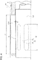
- the frame 3 is inserted into a workpiece W toward its inner peripheral surface Wa (refer to Fig. 4 ), and the mandrel 1 is rotated for finishing the inner peripheral surface Wa.
- the frame 3 is cylindrical, and includes a rear first frame 31 and a front second frame 32.
- the first frame 31 and the second frame 32 are joined together with screws in a separable manner.
- the frame 3 holds multiple rollers 5 that roll on the outer peripheral surface of the mandrel 1 when driven by the rotating mandrel 1.
- the multiple rollers 5 include multiple first rollers 51 and multiple second rollers 52.
- the first rollers 51 and the second rollers 52 are collectively referred to as the rollers 5.
- the mandrel 1 is a round rod as a whole.
- the mandrel 1 includes the shank 11 at the rear in the axial direction, which is attachable to a finishing machine (not shown) such as a machining center.
- the mandrel 1 includes a body 13 at the front, and an intermediate portion 12 in its substantially middle.
- the body 13 is tapered to have a diameter gradually decreasing toward the front of the mandrel 1 (to the left in Fig. 1 ).
- the body 13 includes a polygonal member 14 in its substantially middle.
- the polygonal member 14 includes flat portions 15 and curved portions 16.
- the flat portions 15 are flat surfaces slightly inward from the outer peripheral surface of the body 13.
- the multiple flat portions 15 are circumferentially arranged at small intervals around the mandrel 1.
- the curved portions 16 are on (or having the same diameter as) the outer peripheral surface of the body 13 and extend slightly outward from the flat portions 15. Each curved portion 16 is arranged between two adjacent flat portions 15.
- the polygonal member 14 has a substantially polygonal cross section (a substantially regular decagon in Fig. 2 ) including the curved portions 16 as vertexes and the flat portions 15 as sides.
- the polygonal member 14 is substantially polygonal as viewed in a cross section perpendicular to the axial direction.
- the tool has surfaces having a smooth curvature between the flat portions 15 and the curved portions 16 to allow the second rollers 52 to roll smoothly.
- the frame 3 is fitted onto the mandrel 1 to have the first rollers 51 arranged on the body 13 across the polygonal member 14 (described in detail later). This allows the first rollers 51 to come in contact with the outer peripheral surface of the body 13 without touching the flat portions 15.
- the second rollers 52 come in contact with only the polygonal member 14.
- the shank 11 may be selectable from various shapes attachable to a finishing machine, other than being straight as in the present embodiment.
- the shank 11 may be tapered.
- the first rollers 51 and the second rollers 52 are arranged alternately at intervals on the same circumference as the frame 3.
- the rollers 5 (the first rollers 51 and the second rollers 52) are mounted on the frame 3 with their axes extending in the axial direction of the frame 3 and the mandrel 1.
- the first rollers 51 have a length L1 greater than a length L2 of the second rollers 52.
- the second rollers 52 have a diameter D2 smaller than a diameter D1 of the first rollers 51.
- the first rollers 51 and the second rollers 52 have their diameters gradually decreasing toward the rear end of the mandrel 1 (to the right in Figs. 3A and 3B ), or in other words, tapered in the direction opposite to the body 13. More specifically, the first rollers 51 and the second rollers 52 have the front end diameters D1 and D2 slightly larger than their rear end diameters D1a and D2a.
- the rollers 5 herein have a taper ratio that is 1/2 of the taper ratio of the body 13.
- the polygonal member 14 has a length L3 in the axial direction greater than the length L2 of the second rollers 52 and smaller than the length L1 of the first rollers 51.
- Fig. 4 is a cross-sectional view of the tool in the axial direction showing the first rollers 51 arranged circumferentially and facing the flat portions 15.
- the first rollers 51 have their two axial ends located beyond the two axial ends of the polygonal member 14.
- the first rollers 51 have their two ends in contact with the outer peripheral surface of the body 13, thus leaving a slight clearance C between the substantially middle portions of the first rollers 51 and the flat portions 15.
- the first rollers 51 have their two ends supported by the outer peripheral surface of the body 13, and the substantially middle portions of the first rollers 51 having no contact with the surfaces of the flat portions 15.
- the polygonal member 14 has their two axial ends located beyond the two axial ends of the second rollers 52. This allows the second rollers 52 to come in contact with the flat portions 15. The second rollers 52 are thus located radially inward when in contact with the flat portions 15 and radially outward when in contact with the curved portions 16. More specifically, the polygonal member 14 rotates the multiple second rollers 52, among the multiple rollers 5, to move inward and outward in the radial direction of the frame 3.
- the inner surface finishing tool 100 includes a tool diameter adjuster 7, which adjusts a tool diameter DA (refer to Fig. 2 ) by axially moving the frame 3.
- the tool diameter DA is the diameter of an envelope circle connecting the outer peripheral surfaces of the multiple rollers 5.
- the length L1 of the first rollers 51 always extends across the flat portions 15 when the frame 3 is axially moved relative to the mandrel 1 using the tool diameter adjuster 7. In other words, operating the tool diameter adjuster 7 causes no contact between the first rollers 51 and the surfaces of the flat portions 15.
- the inner surface finishing tool 100 is inserted into the workpiece W toward the inner peripheral surface Wa while the rollers 5 (the first rollers 51 and the second rollers 52) are located between the body 13 and the inner peripheral surface Wa.
- the mandrel 1, the rollers 5, and the frame 3 are formed from special alloy steel to achieve intended durability and undergo thermal treatment to increase hardness and toughness.
- the durability may further be increased using surface coatings of, for example, diamond-like carbon (DLC), titanium nitride (TIN), or titanium carbonitride (TICN) in accordance with the working conditions.
- DLC diamond-like carbon
- TIN titanium nitride
- TBN titanium carbonitride
- the tool diameter adjuster 7 includes a housing 71, a front cap 72, and an adjustment ring 73.
- the tool diameter adjuster 7 further includes, for example, an adjustment nut 74, a key 75, a bearing 76, and a spring 77 inside the area defined by the housing 71, the front cap 72, and the adjustment ring 73.
- the adjustment nut 74 is screwed with a thread 12a on the intermediate portion 12.
- the adjustment nut 74 includes external teeth 78 on its outer periphery, and an abutment surface, which comes in contact with the bearing 76, on its front end.
- the adjustment ring 73 is supported by the adjustment nut 74 with a snap ring 80 in a relatively rotatable and unremovable manner, and is radially outwardly fitted to the intermediate portion 12 loosely with a predetermined clearance.
- the adjustment ring 73 includes external teeth 79 on its outer periphery, which are similar to the external teeth 78 on the adjustment nut 74. Relative movement of the adjustment ring 73 in the circumferential direction of the mandrel 1 is regulated by the key 75, which is fitted in a keyway 12b on the intermediate portion 12.
- the housing 71 is cylindrical, and has internal teeth 81 and 82, which respectively mesh with the external teeth 78 and 79.
- the front cap 72 is arranged at the front of the housing 71.
- the spring 77 is placed between a stop ring 83, which is attached near the rear end of the frame 3, and the inner side of the front cap 72.
- the housing 71 is held and moved rearward against the urging force of the spring 77. This causes the internal teeth 81 and 82 meshing with the external teeth 78 and 79 to move together. When moving further, the internal teeth 82 are disengaged from the external teeth 79. In this state, the external teeth 78 remain meshing with the internal teeth 81.
- the housing 71 is then rotated while pressed rearward. In this state, the internal teeth 81 mesh with the external teeth 78, whereas the internal teeth 82 are disengaged from the external teeth 79 and freely rotatable.
- the adjustment nut 74 rotates integrally with the housing 71, moving the adjustment nut 74 forward or rearward along the thread 12a as guided by its lead.
- the key 75 moves the adjustment ring 73 along the mandrel 1.
- the adjustment nut 74 moving forward or rearward causes contact between the body 13 and the rollers 5 at positions shifted in the axial direction of the mandrel 1. This allows the tool diameter DA to change to a desired value in accordance with the diameter of the body 13 at the shifted position of contact between the body 13 and the rollers 5.
- the housing 71 When the tool diameter DA reaches the desired value, the housing 71 is released to stop adjusting the tool diameter DA.
- the spring 77 which has been compressed, stretches and presses the front cap 72 forward. This causes the housing 71 to move forward together until coming in contact with the adjustment ring 73 and stops. In this state, the internal teeth 81 and 82 respectively mesh with the external teeth 78 and 79, and the adjustment ring 73 is locked by the key 75 and the keyway 12b and is not rotatable.
- the housing 71 is not rotatable relative to the mandrel 1.
- the machining procedure for finishing the inner peripheral surface Wa of the workpiece W with the inner surface finishing tool 100 will now be described.
- the machining procedure includes an adjustment process, a machining process, and a tool withdrawal/removal process.
- the tool diameter DA for the rollers 5 is adjusted. More specifically, the housing 71 is held and moved toward the driving end of the mandrel 1, or specifically the shank 11. The housing 71 is then rotated. The housing 71 is rotated until the tool diameter DA reaches a desired diameter, and then is released. The spring 77 then urges the housing 71 to the initial position, automatically locking the rotation of the housing 71. This completes the setting to the desired tool diameter DA. The tool diameter DA is measured with a gauge (not shown) to determine whether the tool diameter DA has been set correctly.
- the shank 11 is attached to a finishing machine.
- the inner surface finishing tool 100 is moved to an area to be finished on the inner peripheral surface Wa.
- the finishing machine is driven to rotate the mandrel 1.
- the mandrel 1 may rotate clockwise as viewed from the front, causing the rollers 5 to rotate (spin) counterclockwise along the outer peripheral surface of the mandrel 1.
- the rollers 5 on the fixed workpiece W rotate clockwise while spinning counterclockwise along the inner peripheral surface Wa and the outer peripheral surface of the body 13.
- the first rollers 51 are arranged across the flat portions 15 and come in contact with the outer peripheral surface of the body 13.
- the first rollers 51 have no contact with the flat portions 15, irrespective of the rotational direction position of the mandrel 1.
- the first rollers 51 do not move relative to the radial direction of the frame 3 while spinning as the mandrel 1 rotates.
- the first rollers 51 enable the operator to burnish the inner peripheral surface Wa in a stable manner.
- the first rollers 51 are in constant contact with the inner peripheral surface Wa and allow the sun-and-planet motion of the frame 3. The burnishing amount may be minimized to provide a minimum load that allows the sun-and-planet motion.
- the second rollers 52 operate differently from the first rollers 51 when the mandrel 1 rotates.
- the second rollers 52 rotate clockwise while spinning counterclockwise along the outer peripheral surface of the body 13.
- the second rollers 52 travel while passing along the flat portions 15 and the curved portions 16 alternately.
- the flat portions 15 and the curved portions 16 have different heights (the clearance C in Fig. 4 ) to cause the second rollers 52 to vibrate in the radial direction of the frame 3 while rolling on the inner peripheral surface Wa.
- the second rollers 52 move radially inward and outward to strike the inner peripheral surface Wa.
- the polygonal member 14 causes the second rollers 52 to strike the inner peripheral surface Wa intermittently. The impact when the second rollers 52 strike the surface is used for peening or smoothing the unevenness of the inner peripheral surface Wa.
- the inner surface finishing tool 100 is moved axially until separating from the inner peripheral surface Wa.
- the inner surface finishing tool 100 receives the frictional force (resistance) on the inner peripheral surface Wa to compress the spring 77.
- This causes the frame 3 to move forward relative to the mandrel 1.
- the tool diameter DA decreases automatically. This disables the inner surface finishing tool 100 from machining when withdrawn to the initial position.
- the inner surface finishing tool 100 is then removed from the finishing machine to complete the machining procedure for finishing the inner peripheral surface Wa.
- the multiple rollers 5, which are held by the frame 3, include the multiple first rollers 51 and the multiple second rollers 52.
- the mandrel 1 includes the polygonal member 14 that rotates the multiple second rollers 52 to move inward and outward in the radial direction of the frame 3.
- the first rollers 51 perform burnishing while serving as a guide for allowing the sun-and-planet motion of the frame 3, whereas the second rollers 52 perform peening by intermittently striking the inner peripheral surface Wa.
- This allows regular sun-and-planet motion of the frame 3 for uniformly machining the inner peripheral surface Wa and smoothing the unevenness of the inner peripheral surface Wa by peening.
- the first rollers 51 and the second rollers 52 have their side surfaces in contact with the inner peripheral surface Wa to provide improved finished surfaces in a wide area.
- peening improves the hardness of the target surface and applies compressive residual stress to improve the strength of the workpiece W.
- Peening improves the surface roughness of the inner peripheral surface Wa, thus enabling machining of the workpiece W without increasing the burnishing amount.
- the burnishing amount can be minimized to allow for the sun-and-planet motion of the frame 3.
- the tool thus reduces deformation such as edge wear at the opening of a workpiece, or deterioration of its geometrical tolerances including circularity and cylindricity during machining of the inner peripheral surface Wa, enabling finishing with high accuracy.
- the rollers 5 for finishing the workpiece W serve as a guide for enabling the sun-and-planet motion of the frame 3 using the first roller 51 and as a peening unit for smoothing the unevenness using the second rollers 52.
- a known technique cannot use a large burnishing amount that can obstruct the sun-and-planet motion and thus has its uses limited to a workpiece W made of aluminum
- the tool according to the present embodiment is usable for a wide range of workpieces W made of, for example, iron materials.
- the workpiece W may be, for example, an engine component including a cylinder bore, a piston, a connecting rod, and a rocker arm, or a brake component including a master cylinder, a steering system, a transmission, and a suspension.
- the inner surface finishing tool 100 according to the present embodiment has a wide range of applications for machining components having sliding surfaces with an intended surface roughness and strength.
- the inner surface finishing tool 100 for machining a workpiece W made of a material machinable with a relatively large burnishing amount prevents deformation at the opening of a workpiece or deterioration of its geometrical tolerances during machining of the inner peripheral surface Wa.
- the quality of the finished workpiece W is typically adjustable by increasing and decreasing the burnishing amount
- the quality of the finished product is adjusted by the inner surface finishing tool 100 according to the present embodiment by increasing and decreasing the rotational velocity of the mandrel 1 during machining.
- Increasing or decreasing the rotational velocity of the mandrel 1 adjusts the impact with which the second rollers 52 strike the inner peripheral surface Wa to adjust surface roughness. This eliminates the adjustment of the tool diameter DA and improves the efficiency of the finishing processes.
- the first rollers 51 have the length L1 greater than the second rollers 52, which have the length L2.
- the first rollers 51 and the second rollers 52 are alternately arranged at intervals on the same circumference of the frame 3.
- the polygonal member 14 has the axial length L3 greater than the length L2 of the second rollers 52 and smaller than the length L1 of the first rollers 51.
- the polygonal member 14 has its two axial ends located beyond the two axial ends of the second rollers 52.
- the first rollers 51 have their two axial ends located beyond the two axial ends of the polygonal member 14.
- first rollers 51 and the second rollers 52 are arranged on the same circumference, with the first rollers 51 in contact with the outer peripheral surface of the body 13 across the flat portions 15 and the second rollers 52 in contact with the flat portions 15.
- the inner surface finishing tool 100 can be compact and lightweight.
- the second rollers 52 have the diameter D2 smaller than the diameter D1 of the first rollers 51.
- the first rollers 51 as a guide and the second rollers 52 as a peening unit achieve their functions in a more mutually distinctive and reliable manner, providing stable finishing.
- the outer peripheral surface of the mandrel 1, which comes in contact with the rollers 5, is tapered to have a diameter gradually decreasing toward the front end of the mandrel 1.
- the rollers 5 is also tapered to have their diameters gradually decreasing toward the rear end of the mandrel 1.
- the inner surface finishing tool 100 includes the tool diameter adjuster 7 for adjusting the tool diameter DA by moving the frame 3 in the axial direction. This structure allows adjustment of the dimensions or the surface roughness of the finished inner peripheral surface Wa.
- the present invention is not limited to the structures described in the embodiment.
- the present invention may be modified variously without departing from the scope and spirit of the invention, including combining or selecting the components described in the above embodiments as appropriate. Further, the components in the above embodiments may be added, eliminated, or substituted.
- first rollers 51 and the second rollers 52 are arranged on the same circumference of the frame 3 in the above embodiment, they may be displaced in the axial direction.
- first rollers 51 may be arranged frontward at the frame 3 on the same circumference
- second rollers 52 may be arranged rearward at the frame 3 on the same circumference.
- the length L1 of the first rollers 51 and the length L2 of the second rollers 52 may be the same or may be different.
- the first rollers 51 and the second rollers 52 may be or may not be at the same circumferential positions on the frame 3.
- the polygonal member 14 is substantially regular decagonal as viewed in cross section perpendicularly to its axis in the above embodiment, the polygonal member 14 may be in the shape of any other substantially regular polygon, such as a substantially regular octagon.
- the body 13 and the rollers 5 are tapered in the above embodiment, they may be straight (columnar). In this case, the tool diameter adjuster 7 may be eliminated.
- the finishing machine to which the inner surface finishing tool 100 is attached is the machining center in the above embodiment, the finishing machine may be another finishing machine, such as a lathe.
- a lathe When the finishing machine is a lathe, a workpiece is rotated while the mandrel is fixed. As a result, the mandrel rotates relative to the workpiece.
Landscapes
- Engineering & Computer Science (AREA)
- Mechanical Engineering (AREA)
- Finish Polishing, Edge Sharpening, And Grinding By Specific Grinding Devices (AREA)
- Shaping Metal By Deep-Drawing, Or The Like (AREA)
Abstract
Description
- The present invention relates to an inner surface finishing tool for finishing the inner peripheral surface of a workpiece. 2. Description of the Background
- The automotive industry, the electronic equipment industry, and the semiconductor industry all use components with higher accuracy. Components with mirror-finished surfaces after finishing may have an increasing demand for their surface roughness to fall under close dimensional or geometrical tolerances.
- Such components with close geometrical tolerances including circularity or cylindricity undergo finishing using an inner surface finishing tool to achieve intended accuracy.
- A known inner surface finishing tool may be a roller burnishing tool for machining the inner peripheral surface of a workpiece to have an intended surface roughness and an increased surface hardness by rotating its rollers while pressing them against the surface (refer to, for example, Japanese Unexamined Utility Model Application Publication No.
S62-25151 - Patent Literature 1 describes a roller peening tool for peening while burnishing at the same time, by rotating a polygonal shaft and thus vibrating rollers.
- A known roller burnishing tool may apply a large stress (burnishing amount) to a metal surface to cause plastic deformation. The burnishing amount herein refers to a difference between the tool diameter and the pre-machined inner diameter of the workpiece. Machining of the inner peripheral surface of a workpiece using this tool may cause deformation such as edge wear at the opening of the workpiece, or deterioration of its geometrical tolerances including circularity and cylindricity.
- A known roller peening tool is used for finishing the inner peripheral surface of a workpiece by causing rollers to strike the workpiece intermittently. A large burnishing amount may prevent a frame (retainer) holding the rollers from rotating and obstruct the sun-and-planet motion for uniformly machining the entire inner peripheral surface of the workpiece. A known roller peening tool thus has uses limited to workpieces of materials with a low elastic modulus, such as aluminum, with a relatively small burnishing amount.
- One or more aspects of the present invention are directed to an inner surface finishing tool for machining a workpiece made of a material machinable with a relatively large burnishing amount while reducing deformation at the opening of the workpiece or deterioration of its geometrical tolerance during machining of the inner peripheral surface.
- One aspect of the present invention provides an inner surface finishing tool for finishing an inner peripheral surface of a workpiece, the tool including:
- a mandrel rotatable relative to the workpiece, the mandrel including a polygonal member; and
- a frame that is cylindrical and fitted onto the mandrel in a rotatable manner, the frame having an axis extending in an axial direction of the mandrel, the frame holding a plurality of first rollers and a plurality of second rollers rollable on an outer peripheral surface of the mandrel,
- wherein the polygonal member is configured to rotate the plurality of second rollers to move inward and outward in a radial direction of the frame.
- The inner surface finishing tool according to the above aspect of the present invention enables machining of a workpiece made of a material machinable with a relatively large burnishing amount while reducing deformation at the opening of the workpiece deterioration of its geometrical tolerances during machining of the inner peripheral surface.
-
-
Fig. 1 is a side view of an inner surface finishing tool according to one embodiment showing its overall structure, having its upper half shown in cross section. -
Fig. 2 is a cross-sectional view taken along line II-II inFig. 1 . -
Fig. 3A is a side view of a first roller shown inFig. 1 , andFig. 3B is a side view of a second roller shown inFig. 1 . -
Fig. 4 is a cross-sectional view of the tool in the axial direction showing the first rollers arranged circumferentially and facing a flat portion of a polygonal member. - An embodiment will now be described in detail with reference to the drawings.
- In each drawing, common or identical components are given the same reference numerals and will not be described repeatedly.
-
Fig. 1 is a side view of an innersurface finishing tool 100 according to one embodiment showing its overall structure.Fig. 1 shows the upper half of the tool in cross section.Fig. 2 is a cross-sectional view taken along line II-II inFig. 1 .Fig. 3A is a side view of afirst roller 51 shown inFig. 1 .Fig. 3B is a side view of asecond roller 52 shown inFig. 1 . For ease of explanation, the right inFig. 1 (toward a shank 11) is referred to as the rear, and the left inFig. 1 is referred to as the front or forward. - As shown in
Fig. 1 , the innersurface finishing tool 100 according to the present embodiment includes a mandrel 1 and acylindrical frame 3. The mandrel 1 is attached to a machining center (not shown) as a finishing machine, and is rotated. Theframe 3 is fitted onto the mandrel 1 in a rotatable manner. Theframe 3 is inserted into a workpiece W toward its inner peripheral surface Wa (refer toFig. 4 ), and the mandrel 1 is rotated for finishing the inner peripheral surface Wa. - The
frame 3 is cylindrical, and includes a rearfirst frame 31 and a frontsecond frame 32. Thefirst frame 31 and thesecond frame 32 are joined together with screws in a separable manner. Theframe 3 holdsmultiple rollers 5 that roll on the outer peripheral surface of the mandrel 1 when driven by the rotating mandrel 1. Themultiple rollers 5 include multiplefirst rollers 51 and multiplesecond rollers 52. Thefirst rollers 51 and thesecond rollers 52 are collectively referred to as therollers 5. - The mandrel 1 is a round rod as a whole. The mandrel 1 includes the
shank 11 at the rear in the axial direction, which is attachable to a finishing machine (not shown) such as a machining center. The mandrel 1 includes abody 13 at the front, and anintermediate portion 12 in its substantially middle. - The
body 13 is tapered to have a diameter gradually decreasing toward the front of the mandrel 1 (to the left inFig. 1 ). Thebody 13 includes apolygonal member 14 in its substantially middle. - The
polygonal member 14 includesflat portions 15 andcurved portions 16. Theflat portions 15 are flat surfaces slightly inward from the outer peripheral surface of thebody 13. The multipleflat portions 15 are circumferentially arranged at small intervals around the mandrel 1. Thecurved portions 16 are on (or having the same diameter as) the outer peripheral surface of thebody 13 and extend slightly outward from theflat portions 15. Eachcurved portion 16 is arranged between two adjacentflat portions 15. - As shown in
Fig. 2 , thepolygonal member 14 has a substantially polygonal cross section (a substantially regular decagon inFig. 2 ) including thecurved portions 16 as vertexes and theflat portions 15 as sides. In other words, thepolygonal member 14 is substantially polygonal as viewed in a cross section perpendicular to the axial direction. The tool has surfaces having a smooth curvature between theflat portions 15 and thecurved portions 16 to allow thesecond rollers 52 to roll smoothly. - As shown in
Fig. 1 , theframe 3 is fitted onto the mandrel 1 to have thefirst rollers 51 arranged on thebody 13 across the polygonal member 14 (described in detail later). This allows thefirst rollers 51 to come in contact with the outer peripheral surface of thebody 13 without touching theflat portions 15. Thesecond rollers 52 come in contact with only thepolygonal member 14. Theshank 11 may be selectable from various shapes attachable to a finishing machine, other than being straight as in the present embodiment. For example, theshank 11 may be tapered. - The
first rollers 51 and thesecond rollers 52 are arranged alternately at intervals on the same circumference as theframe 3. The rollers 5 (thefirst rollers 51 and the second rollers 52) are mounted on theframe 3 with their axes extending in the axial direction of theframe 3 and the mandrel 1. - As shown in
Figs. 3A and 3B , thefirst rollers 51 have a length L1 greater than a length L2 of thesecond rollers 52. Thesecond rollers 52 have a diameter D2 smaller than a diameter D1 of thefirst rollers 51. - The
first rollers 51 and thesecond rollers 52 have their diameters gradually decreasing toward the rear end of the mandrel 1 (to the right inFigs. 3A and 3B ), or in other words, tapered in the direction opposite to thebody 13. More specifically, thefirst rollers 51 and thesecond rollers 52 have the front end diameters D1 and D2 slightly larger than their rear end diameters D1a and D2a. Therollers 5 herein have a taper ratio that is 1/2 of the taper ratio of thebody 13. - As shown in
Fig. 1 , thepolygonal member 14 has a length L3 in the axial direction greater than the length L2 of thesecond rollers 52 and smaller than the length L1 of thefirst rollers 51. -
Fig. 4 is a cross-sectional view of the tool in the axial direction showing thefirst rollers 51 arranged circumferentially and facing theflat portions 15. - As shown in
Fig. 4 , thefirst rollers 51 have their two axial ends located beyond the two axial ends of thepolygonal member 14. Thus, thefirst rollers 51 have their two ends in contact with the outer peripheral surface of thebody 13, thus leaving a slight clearance C between the substantially middle portions of thefirst rollers 51 and theflat portions 15. More specifically, thefirst rollers 51 have their two ends supported by the outer peripheral surface of thebody 13, and the substantially middle portions of thefirst rollers 51 having no contact with the surfaces of theflat portions 15. - As shown in
Fig. 1 , thepolygonal member 14 has their two axial ends located beyond the two axial ends of thesecond rollers 52. This allows thesecond rollers 52 to come in contact with theflat portions 15. Thesecond rollers 52 are thus located radially inward when in contact with theflat portions 15 and radially outward when in contact with thecurved portions 16. More specifically, thepolygonal member 14 rotates the multiplesecond rollers 52, among themultiple rollers 5, to move inward and outward in the radial direction of theframe 3. - The inner
surface finishing tool 100 includes atool diameter adjuster 7, which adjusts a tool diameter DA (refer toFig. 2 ) by axially moving theframe 3. The tool diameter DA is the diameter of an envelope circle connecting the outer peripheral surfaces of themultiple rollers 5. - The length L1 of the
first rollers 51 always extends across theflat portions 15 when theframe 3 is axially moved relative to the mandrel 1 using thetool diameter adjuster 7. In other words, operating thetool diameter adjuster 7 causes no contact between thefirst rollers 51 and the surfaces of theflat portions 15. - As shown in
Fig. 4 , the innersurface finishing tool 100 is inserted into the workpiece W toward the inner peripheral surface Wa while the rollers 5 (thefirst rollers 51 and the second rollers 52) are located between thebody 13 and the inner peripheral surface Wa. - The mandrel 1, the
rollers 5, and theframe 3 are formed from special alloy steel to achieve intended durability and undergo thermal treatment to increase hardness and toughness. The durability may further be increased using surface coatings of, for example, diamond-like carbon (DLC), titanium nitride (TIN), or titanium carbonitride (TICN) in accordance with the working conditions. - The
tool diameter adjuster 7 includes ahousing 71, afront cap 72, and anadjustment ring 73. Thetool diameter adjuster 7 further includes, for example, anadjustment nut 74, a key 75, abearing 76, and aspring 77 inside the area defined by thehousing 71, thefront cap 72, and theadjustment ring 73. Theadjustment nut 74 is screwed with athread 12a on theintermediate portion 12. Theadjustment nut 74 includesexternal teeth 78 on its outer periphery, and an abutment surface, which comes in contact with thebearing 76, on its front end. Theadjustment ring 73 is supported by theadjustment nut 74 with asnap ring 80 in a relatively rotatable and unremovable manner, and is radially outwardly fitted to theintermediate portion 12 loosely with a predetermined clearance. Theadjustment ring 73 includesexternal teeth 79 on its outer periphery, which are similar to theexternal teeth 78 on theadjustment nut 74. Relative movement of theadjustment ring 73 in the circumferential direction of the mandrel 1 is regulated by the key 75, which is fitted in akeyway 12b on theintermediate portion 12. - The
housing 71 is cylindrical, and hasinternal teeth external teeth front cap 72 is arranged at the front of thehousing 71. Thespring 77 is placed between astop ring 83, which is attached near the rear end of theframe 3, and the inner side of thefront cap 72. - To adjust the tool diameter DA using the
tool diameter adjuster 7, thehousing 71 is held and moved rearward against the urging force of thespring 77. This causes theinternal teeth external teeth internal teeth 82 are disengaged from theexternal teeth 79. In this state, theexternal teeth 78 remain meshing with theinternal teeth 81. - The
housing 71 is then rotated while pressed rearward. In this state, theinternal teeth 81 mesh with theexternal teeth 78, whereas theinternal teeth 82 are disengaged from theexternal teeth 79 and freely rotatable. As thehousing 71 is rotated, theadjustment nut 74 rotates integrally with thehousing 71, moving theadjustment nut 74 forward or rearward along thethread 12a as guided by its lead. As theadjustment nut 74 moves forward or rearward while rotating, the key 75 moves theadjustment ring 73 along the mandrel 1. - The
adjustment nut 74 moving forward or rearward causes contact between thebody 13 and therollers 5 at positions shifted in the axial direction of the mandrel 1. This allows the tool diameter DA to change to a desired value in accordance with the diameter of thebody 13 at the shifted position of contact between thebody 13 and therollers 5. - When the tool diameter DA reaches the desired value, the
housing 71 is released to stop adjusting the tool diameter DA. Thespring 77, which has been compressed, stretches and presses thefront cap 72 forward. This causes thehousing 71 to move forward together until coming in contact with theadjustment ring 73 and stops. In this state, theinternal teeth external teeth adjustment ring 73 is locked by the key 75 and thekeyway 12b and is not rotatable. Thehousing 71 is not rotatable relative to the mandrel 1. - The machining procedure for finishing the inner peripheral surface Wa of the workpiece W with the inner
surface finishing tool 100 will now be described. The machining procedure includes an adjustment process, a machining process, and a tool withdrawal/removal process. - In the adjustment process, the tool diameter DA for the
rollers 5 is adjusted. More specifically, thehousing 71 is held and moved toward the driving end of the mandrel 1, or specifically theshank 11. Thehousing 71 is then rotated. Thehousing 71 is rotated until the tool diameter DA reaches a desired diameter, and then is released. Thespring 77 then urges thehousing 71 to the initial position, automatically locking the rotation of thehousing 71. This completes the setting to the desired tool diameter DA. The tool diameter DA is measured with a gauge (not shown) to determine whether the tool diameter DA has been set correctly. - In the machining process, the
shank 11 is attached to a finishing machine. The innersurface finishing tool 100 is moved to an area to be finished on the inner peripheral surface Wa. The finishing machine is driven to rotate the mandrel 1. The mandrel 1 may rotate clockwise as viewed from the front, causing therollers 5 to rotate (spin) counterclockwise along the outer peripheral surface of the mandrel 1. Therollers 5 on the fixed workpiece W rotate clockwise while spinning counterclockwise along the inner peripheral surface Wa and the outer peripheral surface of thebody 13. - The
first rollers 51 are arranged across theflat portions 15 and come in contact with the outer peripheral surface of thebody 13. Thefirst rollers 51 have no contact with theflat portions 15, irrespective of the rotational direction position of the mandrel 1. Thus, thefirst rollers 51 do not move relative to the radial direction of theframe 3 while spinning as the mandrel 1 rotates. Thefirst rollers 51 enable the operator to burnish the inner peripheral surface Wa in a stable manner. Thefirst rollers 51 are in constant contact with the inner peripheral surface Wa and allow the sun-and-planet motion of theframe 3. The burnishing amount may be minimized to provide a minimum load that allows the sun-and-planet motion. - The
second rollers 52 operate differently from thefirst rollers 51 when the mandrel 1 rotates. In the same manner as thefirst rollers 51, thesecond rollers 52 rotate clockwise while spinning counterclockwise along the outer peripheral surface of thebody 13. Thesecond rollers 52 travel while passing along theflat portions 15 and thecurved portions 16 alternately. Theflat portions 15 and thecurved portions 16 have different heights (the clearance C inFig. 4 ) to cause thesecond rollers 52 to vibrate in the radial direction of theframe 3 while rolling on the inner peripheral surface Wa. Thesecond rollers 52 move radially inward and outward to strike the inner peripheral surface Wa. In other words, thepolygonal member 14 causes thesecond rollers 52 to strike the inner peripheral surface Wa intermittently. The impact when thesecond rollers 52 strike the surface is used for peening or smoothing the unevenness of the inner peripheral surface Wa. - In the tool withdrawal/removal process, the inner
surface finishing tool 100 is moved axially until separating from the inner peripheral surface Wa. The innersurface finishing tool 100 receives the frictional force (resistance) on the inner peripheral surface Wa to compress thespring 77. This causes theframe 3 to move forward relative to the mandrel 1. Thus, the tool diameter DA decreases automatically. This disables the innersurface finishing tool 100 from machining when withdrawn to the initial position. The innersurface finishing tool 100 is then removed from the finishing machine to complete the machining procedure for finishing the inner peripheral surface Wa. - In the present embodiment, the
multiple rollers 5, which are held by theframe 3, include the multiplefirst rollers 51 and the multiplesecond rollers 52. The mandrel 1 includes thepolygonal member 14 that rotates the multiplesecond rollers 52 to move inward and outward in the radial direction of theframe 3. - Thus, the
first rollers 51 perform burnishing while serving as a guide for allowing the sun-and-planet motion of theframe 3, whereas thesecond rollers 52 perform peening by intermittently striking the inner peripheral surface Wa. This allows regular sun-and-planet motion of theframe 3 for uniformly machining the inner peripheral surface Wa and smoothing the unevenness of the inner peripheral surface Wa by peening. Thefirst rollers 51 and thesecond rollers 52 have their side surfaces in contact with the inner peripheral surface Wa to provide improved finished surfaces in a wide area. Moreover, peening improves the hardness of the target surface and applies compressive residual stress to improve the strength of the workpiece W. - Peening improves the surface roughness of the inner peripheral surface Wa, thus enabling machining of the workpiece W without increasing the burnishing amount. The burnishing amount can be minimized to allow for the sun-and-planet motion of the
frame 3. The tool thus reduces deformation such as edge wear at the opening of a workpiece, or deterioration of its geometrical tolerances including circularity and cylindricity during machining of the inner peripheral surface Wa, enabling finishing with high accuracy. - The
rollers 5 for finishing the workpiece W serve as a guide for enabling the sun-and-planet motion of theframe 3 using thefirst roller 51 and as a peening unit for smoothing the unevenness using thesecond rollers 52. Although a known technique cannot use a large burnishing amount that can obstruct the sun-and-planet motion and thus has its uses limited to a workpiece W made of aluminum, the tool according to the present embodiment is usable for a wide range of workpieces W made of, for example, iron materials. - The workpiece W may be, for example, an engine component including a cylinder bore, a piston, a connecting rod, and a rocker arm, or a brake component including a master cylinder, a steering system, a transmission, and a suspension. As described above, the inner
surface finishing tool 100 according to the present embodiment has a wide range of applications for machining components having sliding surfaces with an intended surface roughness and strength. - The inner
surface finishing tool 100 for machining a workpiece W made of a material machinable with a relatively large burnishing amount prevents deformation at the opening of a workpiece or deterioration of its geometrical tolerances during machining of the inner peripheral surface Wa. - Although the quality of the finished workpiece W is typically adjustable by increasing and decreasing the burnishing amount, the quality of the finished product is adjusted by the inner
surface finishing tool 100 according to the present embodiment by increasing and decreasing the rotational velocity of the mandrel 1 during machining. Increasing or decreasing the rotational velocity of the mandrel 1 adjusts the impact with which thesecond rollers 52 strike the inner peripheral surface Wa to adjust surface roughness. This eliminates the adjustment of the tool diameter DA and improves the efficiency of the finishing processes. - In the present embodiment, the
first rollers 51 have the length L1 greater than thesecond rollers 52, which have the length L2. Thefirst rollers 51 and thesecond rollers 52 are alternately arranged at intervals on the same circumference of theframe 3. Thepolygonal member 14 has the axial length L3 greater than the length L2 of thesecond rollers 52 and smaller than the length L1 of thefirst rollers 51. Thepolygonal member 14 has its two axial ends located beyond the two axial ends of thesecond rollers 52. Thefirst rollers 51 have their two axial ends located beyond the two axial ends of thepolygonal member 14. In this structure, thefirst rollers 51 and thesecond rollers 52 are arranged on the same circumference, with thefirst rollers 51 in contact with the outer peripheral surface of thebody 13 across theflat portions 15 and thesecond rollers 52 in contact with theflat portions 15. The innersurface finishing tool 100 can be compact and lightweight. - In the present embodiment, the
second rollers 52 have the diameter D2 smaller than the diameter D1 of thefirst rollers 51. Thefirst rollers 51 as a guide and thesecond rollers 52 as a peening unit achieve their functions in a more mutually distinctive and reliable manner, providing stable finishing. - In the present embodiment, the outer peripheral surface of the mandrel 1, which comes in contact with the
rollers 5, is tapered to have a diameter gradually decreasing toward the front end of the mandrel 1. Therollers 5 is also tapered to have their diameters gradually decreasing toward the rear end of the mandrel 1. The innersurface finishing tool 100 includes thetool diameter adjuster 7 for adjusting the tool diameter DA by moving theframe 3 in the axial direction. This structure allows adjustment of the dimensions or the surface roughness of the finished inner peripheral surface Wa. - Although the embodiments of the present invention are described above, the present invention is not limited to the structures described in the embodiment. The present invention may be modified variously without departing from the scope and spirit of the invention, including combining or selecting the components described in the above embodiments as appropriate. Further, the components in the above embodiments may be added, eliminated, or substituted.
- For example, although the
first rollers 51 and thesecond rollers 52 are arranged on the same circumference of theframe 3 in the above embodiment, they may be displaced in the axial direction. For example, thefirst rollers 51 may be arranged frontward at theframe 3 on the same circumference, whereas thesecond rollers 52 may be arranged rearward at theframe 3 on the same circumference. In this case, the length L1 of thefirst rollers 51 and the length L2 of thesecond rollers 52 may be the same or may be different. Thefirst rollers 51 and thesecond rollers 52 may be or may not be at the same circumferential positions on theframe 3. - Although the
polygonal member 14 is substantially regular decagonal as viewed in cross section perpendicularly to its axis in the above embodiment, thepolygonal member 14 may be in the shape of any other substantially regular polygon, such as a substantially regular octagon. - Although the
body 13 and therollers 5 are tapered in the above embodiment, they may be straight (columnar). In this case, thetool diameter adjuster 7 may be eliminated. - Although the finishing machine to which the inner
surface finishing tool 100 is attached is the machining center in the above embodiment, the finishing machine may be another finishing machine, such as a lathe. When the finishing machine is a lathe, a workpiece is rotated while the mandrel is fixed. As a result, the mandrel rotates relative to the workpiece. -
- 1
- mandrel
- 13
- body
- 14
- polygonal member
- 15
- flat portion
- 16
- curved portion
- 3
- frame
- 5
- roller
- 51
- first roller
- 52
- second roller
- 7
- tool diameter adjuster
- 100
- inner surface finishing tool
- W
- workpiece
- Wa
- inner peripheral surface
- D1
- first roller diameter
- D2
- second roller diameter
- DA
- tool diameter
Claims (4)
- An inner surface finishing tool for finishing an inner peripheral surface of a workpiece, the tool comprising:a mandrel (1) rotatable relative to the workpiece, the mandrel (1) including a polygonal member (14); anda frame (3) that is cylindrical and fitted onto the mandrel (1) in a rotatable manner, the frame (3) having an axis extending in an axial direction of the mandrel (1), the frame (3) holding a plurality of first rollers (51) and a plurality of second rollers (52) rollable on an outer peripheral surface of the mandrel (1),wherein the polygonal member (14) is configured to rotate the plurality of second rollers (52) to move inward and outward in a radial direction of the frame (3).
- The inner surface finishing tool according to claim 1, wherein
the first rollers (51) have a greater length than the second rollers (52),
the first rollers (51) and the second rollers (52) are arranged alternately at intervals on the same circumference of the frame (3),
the polygonal member (14) has, in the axial direction, a greater length than the second rollers (52) and a smaller length than the first rollers (51), and
the polygonal member (14) has, in the axial direction, two ends located beyond two ends of each second roller (52), and the first rollers (51) each have, in the axial direction, two ends located beyond the two ends of the polygonal member (14). - The inner surface finishing tool according to claim 1 or claim 2, wherein
the second rollers (52) have a smaller diameter than the first rollers (51). - The inner surface finishing tool according to any one of claims 1 to 3, wherein
the mandrel (1) has an outer peripheral surface tapered to have a diameter gradually decreasing toward a front end of the mandrel (1),
the first rollers (51) and the second rollers (52) are tapered to have a diameter gradually decreasing toward a rear end of the mandrel (1), and
the inner surface finishing tool further comprises a tool diameter adjuster (7) configured to adjust a tool diameter that is a diameter of an envelope circle connecting outer peripheries of the plurality of first rollers (51) and the plurality of second rollers (52) by axially moving the frame (3).
Applications Claiming Priority (1)
| Application Number | Priority Date | Filing Date | Title |
|---|---|---|---|
| JP2017160077A JP6712113B2 (en) | 2017-08-23 | 2017-08-23 | Interior finishing tools |
Publications (2)
| Publication Number | Publication Date |
|---|---|
| EP3446832A1 true EP3446832A1 (en) | 2019-02-27 |
| EP3446832B1 EP3446832B1 (en) | 2021-01-13 |
Family
ID=63165201
Family Applications (1)
| Application Number | Title | Priority Date | Filing Date |
|---|---|---|---|
| EP18187350.6A Active EP3446832B1 (en) | 2017-08-23 | 2018-08-03 | Inner surface finishing tool |
Country Status (4)
| Country | Link |
|---|---|
| US (1) | US10857650B2 (en) |
| EP (1) | EP3446832B1 (en) |
| JP (1) | JP6712113B2 (en) |
| CN (1) | CN109420977A (en) |
Families Citing this family (3)
| Publication number | Priority date | Publication date | Assignee | Title |
|---|---|---|---|---|
| JP1593594S (en) * | 2017-08-22 | 2017-12-25 | ||
| DE102019111784A1 (en) * | 2019-05-07 | 2020-11-12 | Gühring KG | Roller burnishing tool for machining a workpiece surface |
| CN112405340B (en) * | 2020-11-10 | 2023-05-26 | 杭州科尔贵金属有限公司 | Inner wall calendaring device for gold bracelet production |
Citations (3)
| Publication number | Priority date | Publication date | Assignee | Title |
|---|---|---|---|---|
| US3517533A (en) * | 1967-07-13 | 1970-06-30 | Naradi Narodni Podnik | Assembly for rolling cylindrical surfaces |
| JPS6225151U (en) | 1985-07-26 | 1987-02-16 | ||
| US20120160005A1 (en) * | 2010-12-27 | 2012-06-28 | Sugino Machine Limited | Dimple-forming burnishing tool |
Family Cites Families (3)
| Publication number | Priority date | Publication date | Assignee | Title |
|---|---|---|---|---|
| US5972132A (en) * | 1998-02-11 | 1999-10-26 | Zenith Sintered Products, Inc. | Progressive densification of powder metallurgy circular surfaces |
| JP5291695B2 (en) * | 2010-12-14 | 2013-09-18 | 株式会社スギノマシン | Combined machining tool |
| JP6173977B2 (en) * | 2014-06-24 | 2017-08-02 | 株式会社スギノマシン | Roller burnishing tool |
-
2017
- 2017-08-23 JP JP2017160077A patent/JP6712113B2/en active Active
-
2018
- 2018-08-03 EP EP18187350.6A patent/EP3446832B1/en active Active
- 2018-08-07 US US16/057,196 patent/US10857650B2/en active Active
- 2018-08-08 CN CN201810898394.5A patent/CN109420977A/en active Pending
Patent Citations (3)
| Publication number | Priority date | Publication date | Assignee | Title |
|---|---|---|---|---|
| US3517533A (en) * | 1967-07-13 | 1970-06-30 | Naradi Narodni Podnik | Assembly for rolling cylindrical surfaces |
| JPS6225151U (en) | 1985-07-26 | 1987-02-16 | ||
| US20120160005A1 (en) * | 2010-12-27 | 2012-06-28 | Sugino Machine Limited | Dimple-forming burnishing tool |
Also Published As
| Publication number | Publication date |
|---|---|
| JP6712113B2 (en) | 2020-06-17 |
| US20190061099A1 (en) | 2019-02-28 |
| EP3446832B1 (en) | 2021-01-13 |
| US10857650B2 (en) | 2020-12-08 |
| JP2019038049A (en) | 2019-03-14 |
| CN109420977A (en) | 2019-03-05 |
Similar Documents
| Publication | Publication Date | Title |
|---|---|---|
| US3911707A (en) | Finishing tool | |
| US10857650B2 (en) | Inner surface finishing tool | |
| JP2007301645A (en) | Burnishing tool for forming dimple | |
| US8931320B2 (en) | Dimple-forming burnishing tool | |
| JP6122760B2 (en) | Dimple molding burnishing tool, machine tool, and dimple burnishing method | |
| JP5906117B2 (en) | Dimple forming burnishing tool and workpiece machining method using the same | |
| CN113015586B (en) | Method for producing ball tracks on a workpiece and ball screw nut having ball tracks produced thereby | |
| WO2020230898A1 (en) | Shaft member and method for manufacturing male shaft | |
| CN111940994A (en) | Inner hole rolling tool | |
| RU152121U1 (en) | PRESSURE ROLLER | |
| KR102699347B1 (en) | Roll body for hydrostatic rolling tool and hydrostatic rolling tool with roll body | |
| RU2411099C1 (en) | Embracing spinning device | |
| RU2393039C1 (en) | Device for rotary burnishing of cylindrical shells | |
| JP7210719B2 (en) | Method for machining bearing rings and manufacturing antifriction bearings | |
| US3068550A (en) | Method and mechanism for forming annular grooves | |
| RU2317885C1 (en) | Arrangement for surface plastic deformation of the spherical surfaces of ball pins | |
| RU2303512C1 (en) | Combination diamond-abrasive dwelling tool | |
| RU2409441C1 (en) | Unit of spinning rolls for rotary burnishing of billets | |
| CN109070309A (en) | Rolling tool | |
| Golenkov et al. | Analysis of Methods for the Production of Axisymmetric Parts with Given Specifications | |
| RU2409440C1 (en) | Method of rotary burnishing of billets | |
| RU2297316C1 (en) | Device for expanding openings | |
| RU2298468C1 (en) | Opening static-pulse burnishing method | |
| JP2016060012A (en) | Roller and method for machining microfine recess | |
| RU2589959C2 (en) | Device for strain hardening of inner surface of through holes |
Legal Events
| Date | Code | Title | Description |
|---|---|---|---|
| PUAI | Public reference made under article 153(3) epc to a published international application that has entered the european phase |
Free format text: ORIGINAL CODE: 0009012 |
|
| STAA | Information on the status of an ep patent application or granted ep patent |
Free format text: STATUS: REQUEST FOR EXAMINATION WAS MADE |
|
| 17P | Request for examination filed |
Effective date: 20180803 |
|
| AK | Designated contracting states |
Kind code of ref document: A1 Designated state(s): AL AT BE BG CH CY CZ DE DK EE ES FI FR GB GR HR HU IE IS IT LI LT LU LV MC MK MT NL NO PL PT RO RS SE SI SK SM TR |
|
| AX | Request for extension of the european patent |
Extension state: BA ME |
|
| GRAP | Despatch of communication of intention to grant a patent |
Free format text: ORIGINAL CODE: EPIDOSNIGR1 |
|
| STAA | Information on the status of an ep patent application or granted ep patent |
Free format text: STATUS: GRANT OF PATENT IS INTENDED |
|
| RIC1 | Information provided on ipc code assigned before grant |
Ipc: B23P 9/02 20060101ALI20200901BHEP Ipc: B24B 39/02 20060101AFI20200901BHEP Ipc: B23P 9/04 20060101ALI20200901BHEP |
|
| INTG | Intention to grant announced |
Effective date: 20201006 |
|
| GRAS | Grant fee paid |
Free format text: ORIGINAL CODE: EPIDOSNIGR3 |
|
| GRAA | (expected) grant |
Free format text: ORIGINAL CODE: 0009210 |
|
| STAA | Information on the status of an ep patent application or granted ep patent |
Free format text: STATUS: THE PATENT HAS BEEN GRANTED |
|
| AK | Designated contracting states |
Kind code of ref document: B1 Designated state(s): AL AT BE BG CH CY CZ DE DK EE ES FI FR GB GR HR HU IE IS IT LI LT LU LV MC MK MT NL NO PL PT RO RS SE SI SK SM TR |
|
| REG | Reference to a national code |
Ref country code: GB Ref legal event code: FG4D |
|
| REG | Reference to a national code |
Ref country code: CH Ref legal event code: EP |
|
| REG | Reference to a national code |
Ref country code: IE Ref legal event code: FG4D |
|
| REG | Reference to a national code |
Ref country code: DE Ref legal event code: R096 Ref document number: 602018011765 Country of ref document: DE |
|
| REG | Reference to a national code |
Ref country code: AT Ref legal event code: REF Ref document number: 1354196 Country of ref document: AT Kind code of ref document: T Effective date: 20210215 |
|
| REG | Reference to a national code |
Ref country code: AT Ref legal event code: MK05 Ref document number: 1354196 Country of ref document: AT Kind code of ref document: T Effective date: 20210113 |
|
| REG | Reference to a national code |
Ref country code: NL Ref legal event code: MP Effective date: 20210113 |
|
| REG | Reference to a national code |
Ref country code: LT Ref legal event code: MG9D |
|
| PG25 | Lapsed in a contracting state [announced via postgrant information from national office to epo] |
Ref country code: BG Free format text: LAPSE BECAUSE OF FAILURE TO SUBMIT A TRANSLATION OF THE DESCRIPTION OR TO PAY THE FEE WITHIN THE PRESCRIBED TIME-LIMIT Effective date: 20210413 Ref country code: GR Free format text: LAPSE BECAUSE OF FAILURE TO SUBMIT A TRANSLATION OF THE DESCRIPTION OR TO PAY THE FEE WITHIN THE PRESCRIBED TIME-LIMIT Effective date: 20210414 Ref country code: FI Free format text: LAPSE BECAUSE OF FAILURE TO SUBMIT A TRANSLATION OF THE DESCRIPTION OR TO PAY THE FEE WITHIN THE PRESCRIBED TIME-LIMIT Effective date: 20210113 Ref country code: HR Free format text: LAPSE BECAUSE OF FAILURE TO SUBMIT A TRANSLATION OF THE DESCRIPTION OR TO PAY THE FEE WITHIN THE PRESCRIBED TIME-LIMIT Effective date: 20210113 Ref country code: NO Free format text: LAPSE BECAUSE OF FAILURE TO SUBMIT A TRANSLATION OF THE DESCRIPTION OR TO PAY THE FEE WITHIN THE PRESCRIBED TIME-LIMIT Effective date: 20210413 Ref country code: PT Free format text: LAPSE BECAUSE OF FAILURE TO SUBMIT A TRANSLATION OF THE DESCRIPTION OR TO PAY THE FEE WITHIN THE PRESCRIBED TIME-LIMIT Effective date: 20210513 Ref country code: LT Free format text: LAPSE BECAUSE OF FAILURE TO SUBMIT A TRANSLATION OF THE DESCRIPTION OR TO PAY THE FEE WITHIN THE PRESCRIBED TIME-LIMIT Effective date: 20210113 |
|
| PG25 | Lapsed in a contracting state [announced via postgrant information from national office to epo] |
Ref country code: RS Free format text: LAPSE BECAUSE OF FAILURE TO SUBMIT A TRANSLATION OF THE DESCRIPTION OR TO PAY THE FEE WITHIN THE PRESCRIBED TIME-LIMIT Effective date: 20210113 Ref country code: LV Free format text: LAPSE BECAUSE OF FAILURE TO SUBMIT A TRANSLATION OF THE DESCRIPTION OR TO PAY THE FEE WITHIN THE PRESCRIBED TIME-LIMIT Effective date: 20210113 Ref country code: PL Free format text: LAPSE BECAUSE OF FAILURE TO SUBMIT A TRANSLATION OF THE DESCRIPTION OR TO PAY THE FEE WITHIN THE PRESCRIBED TIME-LIMIT Effective date: 20210113 Ref country code: AT Free format text: LAPSE BECAUSE OF FAILURE TO SUBMIT A TRANSLATION OF THE DESCRIPTION OR TO PAY THE FEE WITHIN THE PRESCRIBED TIME-LIMIT Effective date: 20210113 Ref country code: SE Free format text: LAPSE BECAUSE OF FAILURE TO SUBMIT A TRANSLATION OF THE DESCRIPTION OR TO PAY THE FEE WITHIN THE PRESCRIBED TIME-LIMIT Effective date: 20210113 |
|
| PG25 | Lapsed in a contracting state [announced via postgrant information from national office to epo] |
Ref country code: IS Free format text: LAPSE BECAUSE OF FAILURE TO SUBMIT A TRANSLATION OF THE DESCRIPTION OR TO PAY THE FEE WITHIN THE PRESCRIBED TIME-LIMIT Effective date: 20210513 |
|
| REG | Reference to a national code |
Ref country code: DE Ref legal event code: R097 Ref document number: 602018011765 Country of ref document: DE |
|
| PG25 | Lapsed in a contracting state [announced via postgrant information from national office to epo] |
Ref country code: CZ Free format text: LAPSE BECAUSE OF FAILURE TO SUBMIT A TRANSLATION OF THE DESCRIPTION OR TO PAY THE FEE WITHIN THE PRESCRIBED TIME-LIMIT Effective date: 20210113 Ref country code: EE Free format text: LAPSE BECAUSE OF FAILURE TO SUBMIT A TRANSLATION OF THE DESCRIPTION OR TO PAY THE FEE WITHIN THE PRESCRIBED TIME-LIMIT Effective date: 20210113 Ref country code: SM Free format text: LAPSE BECAUSE OF FAILURE TO SUBMIT A TRANSLATION OF THE DESCRIPTION OR TO PAY THE FEE WITHIN THE PRESCRIBED TIME-LIMIT Effective date: 20210113 |
|
| PLBE | No opposition filed within time limit |
Free format text: ORIGINAL CODE: 0009261 |
|
| STAA | Information on the status of an ep patent application or granted ep patent |
Free format text: STATUS: NO OPPOSITION FILED WITHIN TIME LIMIT |
|
| PG25 | Lapsed in a contracting state [announced via postgrant information from national office to epo] |
Ref country code: DK Free format text: LAPSE BECAUSE OF FAILURE TO SUBMIT A TRANSLATION OF THE DESCRIPTION OR TO PAY THE FEE WITHIN THE PRESCRIBED TIME-LIMIT Effective date: 20210113 Ref country code: SK Free format text: LAPSE BECAUSE OF FAILURE TO SUBMIT A TRANSLATION OF THE DESCRIPTION OR TO PAY THE FEE WITHIN THE PRESCRIBED TIME-LIMIT Effective date: 20210113 Ref country code: RO Free format text: LAPSE BECAUSE OF FAILURE TO SUBMIT A TRANSLATION OF THE DESCRIPTION OR TO PAY THE FEE WITHIN THE PRESCRIBED TIME-LIMIT Effective date: 20210113 |
|
| 26N | No opposition filed |
Effective date: 20211014 |
|
| PG25 | Lapsed in a contracting state [announced via postgrant information from national office to epo] |
Ref country code: AL Free format text: LAPSE BECAUSE OF FAILURE TO SUBMIT A TRANSLATION OF THE DESCRIPTION OR TO PAY THE FEE WITHIN THE PRESCRIBED TIME-LIMIT Effective date: 20210113 Ref country code: ES Free format text: LAPSE BECAUSE OF FAILURE TO SUBMIT A TRANSLATION OF THE DESCRIPTION OR TO PAY THE FEE WITHIN THE PRESCRIBED TIME-LIMIT Effective date: 20210113 |
|
| PG25 | Lapsed in a contracting state [announced via postgrant information from national office to epo] |
Ref country code: SI Free format text: LAPSE BECAUSE OF FAILURE TO SUBMIT A TRANSLATION OF THE DESCRIPTION OR TO PAY THE FEE WITHIN THE PRESCRIBED TIME-LIMIT Effective date: 20210113 |
|
| REG | Reference to a national code |
Ref country code: CH Ref legal event code: PL |
|
| PG25 | Lapsed in a contracting state [announced via postgrant information from national office to epo] |
Ref country code: MC Free format text: LAPSE BECAUSE OF FAILURE TO SUBMIT A TRANSLATION OF THE DESCRIPTION OR TO PAY THE FEE WITHIN THE PRESCRIBED TIME-LIMIT Effective date: 20210113 |
|
| REG | Reference to a national code |
Ref country code: BE Ref legal event code: MM Effective date: 20210831 |
|
| PG25 | Lapsed in a contracting state [announced via postgrant information from national office to epo] |
Ref country code: LI Free format text: LAPSE BECAUSE OF NON-PAYMENT OF DUE FEES Effective date: 20210831 Ref country code: IT Free format text: LAPSE BECAUSE OF FAILURE TO SUBMIT A TRANSLATION OF THE DESCRIPTION OR TO PAY THE FEE WITHIN THE PRESCRIBED TIME-LIMIT Effective date: 20210113 Ref country code: CH Free format text: LAPSE BECAUSE OF NON-PAYMENT OF DUE FEES Effective date: 20210831 |
|
| PG25 | Lapsed in a contracting state [announced via postgrant information from national office to epo] |
Ref country code: IS Free format text: LAPSE BECAUSE OF FAILURE TO SUBMIT A TRANSLATION OF THE DESCRIPTION OR TO PAY THE FEE WITHIN THE PRESCRIBED TIME-LIMIT Effective date: 20210513 Ref country code: LU Free format text: LAPSE BECAUSE OF NON-PAYMENT OF DUE FEES Effective date: 20210803 |
|
| PG25 | Lapsed in a contracting state [announced via postgrant information from national office to epo] |
Ref country code: IE Free format text: LAPSE BECAUSE OF NON-PAYMENT OF DUE FEES Effective date: 20210803 Ref country code: FR Free format text: LAPSE BECAUSE OF NON-PAYMENT OF DUE FEES Effective date: 20210831 Ref country code: BE Free format text: LAPSE BECAUSE OF NON-PAYMENT OF DUE FEES Effective date: 20210831 |
|
| GBPC | Gb: european patent ceased through non-payment of renewal fee |
Effective date: 20220803 |
|
| PG25 | Lapsed in a contracting state [announced via postgrant information from national office to epo] |
Ref country code: NL Free format text: LAPSE BECAUSE OF NON-PAYMENT OF DUE FEES Effective date: 20210113 Ref country code: CY Free format text: LAPSE BECAUSE OF FAILURE TO SUBMIT A TRANSLATION OF THE DESCRIPTION OR TO PAY THE FEE WITHIN THE PRESCRIBED TIME-LIMIT Effective date: 20210113 |
|
| PG25 | Lapsed in a contracting state [announced via postgrant information from national office to epo] |
Ref country code: HU Free format text: LAPSE BECAUSE OF FAILURE TO SUBMIT A TRANSLATION OF THE DESCRIPTION OR TO PAY THE FEE WITHIN THE PRESCRIBED TIME-LIMIT; INVALID AB INITIO Effective date: 20180803 |
|
| PG25 | Lapsed in a contracting state [announced via postgrant information from national office to epo] |
Ref country code: GB Free format text: LAPSE BECAUSE OF NON-PAYMENT OF DUE FEES Effective date: 20220803 |
|
| PGFP | Annual fee paid to national office [announced via postgrant information from national office to epo] |
Ref country code: TR Payment date: 20230801 Year of fee payment: 6 |
|
| PG25 | Lapsed in a contracting state [announced via postgrant information from national office to epo] |
Ref country code: MK Free format text: LAPSE BECAUSE OF FAILURE TO SUBMIT A TRANSLATION OF THE DESCRIPTION OR TO PAY THE FEE WITHIN THE PRESCRIBED TIME-LIMIT Effective date: 20210113 |
|
| PG25 | Lapsed in a contracting state [announced via postgrant information from national office to epo] |
Ref country code: MT Free format text: LAPSE BECAUSE OF FAILURE TO SUBMIT A TRANSLATION OF THE DESCRIPTION OR TO PAY THE FEE WITHIN THE PRESCRIBED TIME-LIMIT Effective date: 20210113 |
|
| PGFP | Annual fee paid to national office [announced via postgrant information from national office to epo] |
Ref country code: DE Payment date: 20240821 Year of fee payment: 7 |