EP3446789A1 - High-volume low-pressure end effector and corresponding method - Google Patents
High-volume low-pressure end effector and corresponding method Download PDFInfo
- Publication number
- EP3446789A1 EP3446789A1 EP18178242.6A EP18178242A EP3446789A1 EP 3446789 A1 EP3446789 A1 EP 3446789A1 EP 18178242 A EP18178242 A EP 18178242A EP 3446789 A1 EP3446789 A1 EP 3446789A1
- Authority
- EP
- European Patent Office
- Prior art keywords
- end effector
- spray head
- fluid
- pressure end
- volume low
- Prior art date
- Legal status (The legal status is an assumption and is not a legal conclusion. Google has not performed a legal analysis and makes no representation as to the accuracy of the status listed.)
- Granted
Links
Images







Classifications
-
- B—PERFORMING OPERATIONS; TRANSPORTING
- B05—SPRAYING OR ATOMISING IN GENERAL; APPLYING FLUENT MATERIALS TO SURFACES, IN GENERAL
- B05B—SPRAYING APPARATUS; ATOMISING APPARATUS; NOZZLES
- B05B1/00—Nozzles, spray heads or other outlets, with or without auxiliary devices such as valves, heating means
- B05B1/14—Nozzles, spray heads or other outlets, with or without auxiliary devices such as valves, heating means with multiple outlet openings; with strainers in or outside the outlet opening
- B05B1/16—Nozzles, spray heads or other outlets, with or without auxiliary devices such as valves, heating means with multiple outlet openings; with strainers in or outside the outlet opening having selectively- effective outlets
-
- B—PERFORMING OPERATIONS; TRANSPORTING
- B05—SPRAYING OR ATOMISING IN GENERAL; APPLYING FLUENT MATERIALS TO SURFACES, IN GENERAL
- B05B—SPRAYING APPARATUS; ATOMISING APPARATUS; NOZZLES
- B05B13/00—Machines or plants for applying liquids or other fluent materials to surfaces of objects or other work by spraying, not covered by groups B05B1/00 - B05B11/00
- B05B13/06—Machines or plants for applying liquids or other fluent materials to surfaces of objects or other work by spraying, not covered by groups B05B1/00 - B05B11/00 specially designed for treating the inside of hollow bodies
- B05B13/0627—Arrangements of nozzles or spray heads specially adapted for treating the inside of hollow bodies
- B05B13/0636—Arrangements of nozzles or spray heads specially adapted for treating the inside of hollow bodies by means of rotatable spray heads or nozzles
-
- B—PERFORMING OPERATIONS; TRANSPORTING
- B05—SPRAYING OR ATOMISING IN GENERAL; APPLYING FLUENT MATERIALS TO SURFACES, IN GENERAL
- B05B—SPRAYING APPARATUS; ATOMISING APPARATUS; NOZZLES
- B05B7/00—Spraying apparatus for discharge of liquids or other fluent materials from two or more sources, e.g. of liquid and air, of powder and gas
- B05B7/02—Spray pistols; Apparatus for discharge
- B05B7/04—Spray pistols; Apparatus for discharge with arrangements for mixing liquids or other fluent materials before discharge
- B05B7/0416—Spray pistols; Apparatus for discharge with arrangements for mixing liquids or other fluent materials before discharge with arrangements for mixing one gas and one liquid
-
- B—PERFORMING OPERATIONS; TRANSPORTING
- B05—SPRAYING OR ATOMISING IN GENERAL; APPLYING FLUENT MATERIALS TO SURFACES, IN GENERAL
- B05B—SPRAYING APPARATUS; ATOMISING APPARATUS; NOZZLES
- B05B13/00—Machines or plants for applying liquids or other fluent materials to surfaces of objects or other work by spraying, not covered by groups B05B1/00 - B05B11/00
- B05B13/005—Machines or plants for applying liquids or other fluent materials to surfaces of objects or other work by spraying, not covered by groups B05B1/00 - B05B11/00 mounted on vehicles or designed to apply a liquid on a very large surface, e.g. on the road, on the surface of large containers
-
- B—PERFORMING OPERATIONS; TRANSPORTING
- B05—SPRAYING OR ATOMISING IN GENERAL; APPLYING FLUENT MATERIALS TO SURFACES, IN GENERAL
- B05B—SPRAYING APPARATUS; ATOMISING APPARATUS; NOZZLES
- B05B13/00—Machines or plants for applying liquids or other fluent materials to surfaces of objects or other work by spraying, not covered by groups B05B1/00 - B05B11/00
- B05B13/02—Means for supporting work; Arrangement or mounting of spray heads; Adaptation or arrangement of means for feeding work
- B05B13/04—Means for supporting work; Arrangement or mounting of spray heads; Adaptation or arrangement of means for feeding work the spray heads being moved during spraying operation
-
- B—PERFORMING OPERATIONS; TRANSPORTING
- B05—SPRAYING OR ATOMISING IN GENERAL; APPLYING FLUENT MATERIALS TO SURFACES, IN GENERAL
- B05B—SPRAYING APPARATUS; ATOMISING APPARATUS; NOZZLES
- B05B13/00—Machines or plants for applying liquids or other fluent materials to surfaces of objects or other work by spraying, not covered by groups B05B1/00 - B05B11/00
- B05B13/02—Means for supporting work; Arrangement or mounting of spray heads; Adaptation or arrangement of means for feeding work
- B05B13/04—Means for supporting work; Arrangement or mounting of spray heads; Adaptation or arrangement of means for feeding work the spray heads being moved during spraying operation
- B05B13/0431—Means for supporting work; Arrangement or mounting of spray heads; Adaptation or arrangement of means for feeding work the spray heads being moved during spraying operation with spray heads moved by robots or articulated arms, e.g. for applying liquid or other fluent material to three-dimensional [3D] surfaces
-
- B—PERFORMING OPERATIONS; TRANSPORTING
- B05—SPRAYING OR ATOMISING IN GENERAL; APPLYING FLUENT MATERIALS TO SURFACES, IN GENERAL
- B05B—SPRAYING APPARATUS; ATOMISING APPARATUS; NOZZLES
- B05B13/00—Machines or plants for applying liquids or other fluent materials to surfaces of objects or other work by spraying, not covered by groups B05B1/00 - B05B11/00
- B05B13/02—Means for supporting work; Arrangement or mounting of spray heads; Adaptation or arrangement of means for feeding work
- B05B13/04—Means for supporting work; Arrangement or mounting of spray heads; Adaptation or arrangement of means for feeding work the spray heads being moved during spraying operation
- B05B13/0431—Means for supporting work; Arrangement or mounting of spray heads; Adaptation or arrangement of means for feeding work the spray heads being moved during spraying operation with spray heads moved by robots or articulated arms, e.g. for applying liquid or other fluent material to three-dimensional [3D] surfaces
- B05B13/0433—Means for supporting work; Arrangement or mounting of spray heads; Adaptation or arrangement of means for feeding work the spray heads being moved during spraying operation with spray heads moved by robots or articulated arms, e.g. for applying liquid or other fluent material to three-dimensional [3D] surfaces the work being vehicle components, e.g. vehicle bodies
-
- B—PERFORMING OPERATIONS; TRANSPORTING
- B05—SPRAYING OR ATOMISING IN GENERAL; APPLYING FLUENT MATERIALS TO SURFACES, IN GENERAL
- B05B—SPRAYING APPARATUS; ATOMISING APPARATUS; NOZZLES
- B05B13/00—Machines or plants for applying liquids or other fluent materials to surfaces of objects or other work by spraying, not covered by groups B05B1/00 - B05B11/00
- B05B13/06—Machines or plants for applying liquids or other fluent materials to surfaces of objects or other work by spraying, not covered by groups B05B1/00 - B05B11/00 specially designed for treating the inside of hollow bodies
- B05B13/0627—Arrangements of nozzles or spray heads specially adapted for treating the inside of hollow bodies
-
- B—PERFORMING OPERATIONS; TRANSPORTING
- B05—SPRAYING OR ATOMISING IN GENERAL; APPLYING FLUENT MATERIALS TO SURFACES, IN GENERAL
- B05B—SPRAYING APPARATUS; ATOMISING APPARATUS; NOZZLES
- B05B15/00—Details of spraying plant or spraying apparatus not otherwise provided for; Accessories
- B05B15/60—Arrangements for mounting, supporting or holding spraying apparatus
- B05B15/65—Mounting arrangements for fluid connection of the spraying apparatus or its outlets to flow conduits
-
- B—PERFORMING OPERATIONS; TRANSPORTING
- B05—SPRAYING OR ATOMISING IN GENERAL; APPLYING FLUENT MATERIALS TO SURFACES, IN GENERAL
- B05B—SPRAYING APPARATUS; ATOMISING APPARATUS; NOZZLES
- B05B7/00—Spraying apparatus for discharge of liquids or other fluent materials from two or more sources, e.g. of liquid and air, of powder and gas
- B05B7/0081—Apparatus supplied with low pressure gas, e.g. "hvlp"-guns; air supplied by a fan
-
- B—PERFORMING OPERATIONS; TRANSPORTING
- B05—SPRAYING OR ATOMISING IN GENERAL; APPLYING FLUENT MATERIALS TO SURFACES, IN GENERAL
- B05B—SPRAYING APPARATUS; ATOMISING APPARATUS; NOZZLES
- B05B7/00—Spraying apparatus for discharge of liquids or other fluent materials from two or more sources, e.g. of liquid and air, of powder and gas
- B05B7/02—Spray pistols; Apparatus for discharge
- B05B7/08—Spray pistols; Apparatus for discharge with separate outlet orifices, e.g. to form parallel jets, i.e. the axis of the jets being parallel, to form intersecting jets, i.e. the axis of the jets converging but not necessarily intersecting at a point
-
- B—PERFORMING OPERATIONS; TRANSPORTING
- B05—SPRAYING OR ATOMISING IN GENERAL; APPLYING FLUENT MATERIALS TO SURFACES, IN GENERAL
- B05B—SPRAYING APPARATUS; ATOMISING APPARATUS; NOZZLES
- B05B7/00—Spraying apparatus for discharge of liquids or other fluent materials from two or more sources, e.g. of liquid and air, of powder and gas
- B05B7/02—Spray pistols; Apparatus for discharge
- B05B7/08—Spray pistols; Apparatus for discharge with separate outlet orifices, e.g. to form parallel jets, i.e. the axis of the jets being parallel, to form intersecting jets, i.e. the axis of the jets converging but not necessarily intersecting at a point
- B05B7/0807—Spray pistols; Apparatus for discharge with separate outlet orifices, e.g. to form parallel jets, i.e. the axis of the jets being parallel, to form intersecting jets, i.e. the axis of the jets converging but not necessarily intersecting at a point to form intersecting jets
- B05B7/0861—Spray pistols; Apparatus for discharge with separate outlet orifices, e.g. to form parallel jets, i.e. the axis of the jets being parallel, to form intersecting jets, i.e. the axis of the jets converging but not necessarily intersecting at a point to form intersecting jets with one single jet constituted by a liquid or a mixture containing a liquid and several gas jets
-
- B—PERFORMING OPERATIONS; TRANSPORTING
- B25—HAND TOOLS; PORTABLE POWER-DRIVEN TOOLS; MANIPULATORS
- B25J—MANIPULATORS; CHAMBERS PROVIDED WITH MANIPULATION DEVICES
- B25J11/00—Manipulators not otherwise provided for
- B25J11/0075—Manipulators for painting or coating
-
- B—PERFORMING OPERATIONS; TRANSPORTING
- B64—AIRCRAFT; AVIATION; COSMONAUTICS
- B64F—GROUND OR AIRCRAFT-CARRIER-DECK INSTALLATIONS SPECIALLY ADAPTED FOR USE IN CONNECTION WITH AIRCRAFT; DESIGNING, MANUFACTURING, ASSEMBLING, CLEANING, MAINTAINING OR REPAIRING AIRCRAFT, NOT OTHERWISE PROVIDED FOR; HANDLING, TRANSPORTING, TESTING OR INSPECTING AIRCRAFT COMPONENTS, NOT OTHERWISE PROVIDED FOR
- B64F5/00—Designing, manufacturing, assembling, cleaning, maintaining or repairing aircraft, not otherwise provided for; Handling, transporting, testing or inspecting aircraft components, not otherwise provided for
Definitions
- the present disclosure relates generally to performing manufacturing operations on components, and more specifically, to applying a fluid to a component. Still more particularly, the present disclosure relates to a high-volume low-pressure end effector configured to apply a fluid to a component.
- Spray applicators apply a fluid coating to a component by propelling and directing the fluid with air. A percentage of the fluid coating will become airborne within the manufacturing environment. Sprayed fluid coating not applied to a component may result in overspray. Overspray produces additional material cost. Overspray may also settle on surrounding structures in the manufacturing environment. The fraction of sprayed fluid coating applied to a component may be described as a coverage percentage.
- Applying a fluid coating inside tight areas of enclosures using spray end effectors may result in less than desirable coverage.
- applying a fluid coating inside tight areas of enclosures may impact ability to access and spray adequately all surfaces using spray end effectors. Maneuvering spray end effectors may be undesirably difficult within tight areas of enclosures.
- Manually applying a fluid coating inside tight areas of enclosures may take an undesirably large amount of time.
- Manually applying a fluid coating inside tight areas of enclosures may take an undesirably large number of human operators.
- Manually applying a fluid coating using human operators may cause an undesirable amount of exposure to the fluid coating or components of the fluid coating for the human operators.
- An illustrative embodiment of the present disclosure provides a high-volume low-pressure end effector.
- the high-volume low-pressure end effector comprises a connection arm and a spray head.
- the connection arm comprises a housing with flexible conduits running through the housing.
- the spray head has integral channels configured to receive air and a fluid from the conduits and deliver the air and the fluid to a number of outlets.
- a fluid and air are supplied through flexible conduits running through a housing of a connection arm to a spray head with integral channels configured to receive the air and the fluid from the conduits and deliver the air and the fluid to a number of outlets of the spray head, wherein the connection arm and spray head are components of a high-volume low-pressure end effector.
- the fluid is sprayed from at least one outlet of the number of outlets and onto surfaces of an enclosure of a structure with a total coverage of at least 90 percent.
- a further illustrative embodiment of the present disclosure provides a high-volume low-pressure end effector.
- the high-volume low-pressure end effector comprises an attachment bracket, a connection arm, fittings, and a spray head.
- the attachment bracket covers valves for air and fluid.
- the connection arm comprises a hollow metal housing with flexible conduits running through the housing. The flexible conduits carry the air and the fluid.
- the fittings connect the flexible conduits to integral channels within a spray head.
- the spray head has integral channels delivering fluid and air to a number of outlets.
- the illustrative embodiments recognize and take into account one or more different considerations. For example, the illustrative embodiments recognize and take into account that spar cavities are large enclosures with tight areas for coating coverage.
- the illustrative embodiments also recognize and take into account that conventional end effectors provide a low effective coverage of the spar cavities.
- the illustrative embodiments recognize and take into account that some conventional end effectors provide approximately 20 percent coverage within spar cavities.
- the illustrative embodiments recognize and take into account that low coverage leads to low utilization of the robotic system.
- the illustrative embodiments recognize and take into account that the low coverage leads to increased flow time.
- the illustrative embodiments recognize and take into account that low coverage may result in a large amount of manual touch-up.
- the illustrative embodiments recognize and take into account that many available spray paints, pigments, and other coatings contain hexavalent chromium.
- the illustrative embodiments recognize and take into account that minimizing human operator exposure to hexavalent chromium is desirable.
- the illustrative embodiments thus recognize and take into account that automating application of paints, pigments, and other coatings is desirable.
- the illustrative embodiments recognize and take into account that some conventional end effectors are made from machined aluminum.
- the illustrative embodiments recognize and take into account that conventional end effectors with machined aluminum blocks are heavier than robotic arm operating payload standards.
- the illustrative examples recognize and take into account that because some conventional end effectors are mostly machined billet aluminum, components of these end effector may be undesirably difficult or expensive to find and replace.
- aircraft 100 has wing 102 and wing 104 attached to body 106.
- Aircraft 100 includes engine 108 attached to wing 102 and engine 110 attached to wing 104.
- Body 106 has tail section 112. Horizontal stabilizer 114, horizontal stabilizer 116, and vertical stabilizer 118 are attached to tail section 112 of body 106.
- Aircraft 100 is an example of an aircraft in which components coated using a high-volume low-pressure end effector may be implemented in accordance with an illustrative embodiment.
- a high-volume low-pressure end effector may be used to apply coatings within wing spar cavities of at least one of wing 102 or wing 104.
- the phrase "at least one of,” when used with a list of items, means different combinations of one or more of the listed items may be used, and only one of each item in the list may be needed. In other words, “at least one of” means any combination of items and number of items may be used from the list, but not all of the items in the list are required.
- the item may be a particular object, a thing, or a category.
- “at least one of item A, item B, or item C” may include, without limitation, item A, item A and item B, or item B. This example also may include item A, item B, and item C, or item B and item C. Of course, any combination of these items may be present. In other examples, "at least one of” may be, for example, without limitation, two of item A, one of item B, and ten of item C; four of item B and seven of item C; or other suitable combinations.
- aircraft 100 is provided for the purposes of illustrating one environment in which different illustrative embodiments may be implemented.
- the illustration of aircraft 100 in Figure 1 is not meant to imply architectural limitations as to the manner in which different illustrative embodiments may be implemented.
- aircraft 100 is shown as a commercial passenger aircraft.
- the different illustrative embodiments may be applied to other types of aircraft, such as a private passenger aircraft, rotorcraft, or other suitable types of aircraft.
- the structure may be, for example, a mobile structure, a stationary structure, a land-based structure, an aquatic-based structure, or a space-based structure. More specifically, the structure may be a surface ship, a tank, a personnel carrier, a train, a spacecraft, a space station, a satellite, a submarine, a manufacturing facility, a building, or other suitable types of structures.
- Manufacturing environment 200 is an illustrative example of an environment in which components of aircraft 100 may be processed.
- fluid 202 may be applied to components of aircraft 100 using high-volume low-pressure end effector 204 in manufacturing environment 200.
- High-volume low-pressure end effector 204 comprises connection arm 206 and spray head 208.
- Connection arm 206 comprises housing 210 with flexible 212 conduits 214 running through housing 210.
- Spray head 208 has integral channels 216 configured to receive air 218 and fluid 202 from conduits 214 and deliver air 218 and fluid 202 to number of outlets 220.
- a "number of items” means one or more items.
- number of outlets 220 has one or more outlets.
- number of outlets 220 comprises first outlet 222 and second outlet 224 connected to integral channels 216.
- First outlet 222 and second outlet 224 may have any desirable orientation relative to each other.
- First outlet 222 and second outlet 224 may be positioned anywhere from approximately zero degrees to approximately one hundred eighty degrees relative to each other.
- first outlet 222 and second outlet 224 are pointed ninety degrees relative to each other.
- first outlet 222 and second outlet 224 are pointed approximately one hundred eighty degrees relative to each other.
- High-volume low-pressure end effector 204 comprises a respective nozzle and aircap for each of first outlet 222 and second outlet 224. As depicted, nozzle 226 and aircap 228 are associated with first outlet 222. Nozzle 230 and aircap 232 are associated with second outlet 224. In some illustrative examples, high-volume low-pressure end effector 204 comprises a respective aircap threaded on to each of number of outlets 220, wherein each respective aircap encloses a respective nozzle within each of number of outlets 220.
- Nozzle 226 and aircap 228 enable high-volume low-pressure application of fluid 202.
- Nozzle 226 pressurizes fluid 202 and distributes the atomized fluid to aircap 228.
- Aircap 228 allows pass-through of fluid 202 and distributes the atomized fluid to manufacturing environment 200.
- Nozzle 226 and aircap 228 enable high-volume low-pressure spray of fluid 202 from first outlet 222.
- Nozzle 230 and aircap 232 enable high-volume low-pressure application of fluid 202.
- Nozzle 230 pressurizes fluid 202 and distributes the pressurized fluid to aircap 232.
- Aircap 232 allows pass-through of fluid 202 and distributes the atomized fluid to manufacturing environment 200.
- Nozzle 230 and aircap 232 enable high-volume low-pressure spray of fluid 202 from second outlet 224.
- a combination of aircap 228 and spray head 208 holds and seals nozzle 226 within first outlet 222.
- aircap 228 is threaded onto spray head 208 to seal aircap 228 against spray head 208.
- additional sealing components such as o-rings or other sealing components are not used to seal aircap 228 to spray head 208.
- weight 234 of high-volume low-pressure end effector 204 may be reduced.
- maintenance time of high-volume low-pressure end effector 204 may be reduced.
- a combination of aircap 232 and spray head 208 holds and seals nozzle 230 within second outlet 224.
- aircap 232 is threaded onto spray head 208 to seal aircap 232 against spray head 208.
- additional sealing components such as o-rings or other sealing components are not used to seal aircap 232 to spray head 208.
- Integral channels 216 distribute air 218 and fluid 202 to the nozzles associated with spray head 208. Integral channels 216 distribute air 218 and fluid 202 to nozzle 226 and nozzle 230.
- Spray head 208 is formed of any desirable material.
- Material 236 is selected to be compatible with use of fluid 202.
- fluid 202 is paint
- material 236 is selected to be paint compatible.
- material 236 is selected to not be reactive to fluid 202 or to solvents used to remove fluid 202 from spray head 208.
- material 236 is stainless steel.
- spray head 208 is monolithic 238.
- spray head 208 is one indivisible component.
- Spray head 208 may be manufactured using any desirable method.
- spray head 208 is formed using an additive manufacturing method.
- spray head 208 is formed by machining.
- spray head 208 may be formed by molding or other manufacturing techniques.
- a manufacturing technique for creating spray head 208 is selected based on at least one of a desirable manufacturing time, a desirable manufacturing cost, a desirable manufacturing accuracy, or any other manufacturing factors.
- Integral channels 216 extend from first end 240 of spray head 208 towards second end 242 of spray head 208. First end 240 is opposite second end 242 of spray head 208. Integral channels 216 have any desirable shape and size to deliver air 218 and fluid 202 to number of outlets 220.
- Fittings 244 connect conduits 214 in connection arm 206 to integral channels 216 of spray head 208. Fittings 244 are associated with inlets 246 of integral channels 216 at first end 240 of spray head 208. Fittings 244 are physically connected to integral channels 216 using any desirable type of connection. In some illustrative examples, fittings 244 are threaded. In these illustrative examples, torque is applied to secure fittings 244 to spray head 208.
- fittings 244 comprise number of air fittings 248 and number of fluid fittings 250.
- number of air fittings 248 comprises two air fittings per outlet, and wherein number of fluid fittings 250 comprises one fluid fitting per outlet.
- a first air fitting supplies air 218 to atomize fluid 202 exiting the respective nozzle.
- a second air fitting supplies air 218 to form shaping air streams. The second air fitting provides shaping air streams to control application of fluid 202 and evenly distribute fluid 202.
- the quantity of conduits 214 is any desirable quantity. In some illustrative examples, the quantity of conduits 214 is equal to the quantity of fittings 244.
- the quantity of conduits 214 is affected by the quantity of outlets in number of outlets 220.
- each outlet of number of outlets 220 will receive air 218 and fluid 202.
- the quantity of conduits 214 will be sufficient to provide air 218 and fluid 202 to each outlet of number of outlets 220.
- conduits 214 contains at least one conduit with fluid 202 and at least two conduits with air 218.
- conduits 214 contains at least two conduits with fluid 202 and at least four conduits with air 218.
- Spray head 208 is replaceable.
- spray head 208 may be replaced with a spray head with a different quantity of outlets.
- conduits 214 may remain in housing 210 after spray head 208 is replaced.
- conduits 214 may contain a larger quantity of conduits than a quantity of outlets or a quantity of nozzles in the replacement spray head.
- First end 240 of spray head 208 is connected to connection arm 206.
- Spray head 208 is connected to connection arm 206 using fasteners 252.
- the connection between connection arm 206 and spray head 208 has a minimal quantity of fasteners 252.
- a minimal quantity of fasteners 252 may reduce weight 234 of high-volume low-pressure end effector 204.
- a minimal quantity of fasteners 252 may also reduce maintenance time for high-volume low-pressure end effector 204.
- Fasteners 252 are selected to not extend from connection arm 206 an undesirable amount.
- first end 240 is inserted into housing 210 prior to connecting spray head 208 and connection arm 206.
- spray head 208 reduces in cross-sectional area moving from first end 240 to second end 242. By reducing in cross-sectional area, spray head 208 may maneuver within tight areas more easily.
- Connection arm 206 has housing 210.
- Housing 210 has cross-section 254.
- Cross-section 254 is selected to accommodate conduits 214.
- cross-section 254 is selected to reduce chances of collision of housing 210 during rotation.
- cross-section 254 is circular 256.
- housing 210 has circular 256 cross-section 254.
- cross-section 254 is circular 256, deflection is lower than for cross-sections with sharp corners.
- housing 210 is hollow 257 to accommodate conduits 214. In some illustrative examples, housing 210 is hollow 257 to reduce weight 234 of high-volume low-pressure end effector 204.
- Connection arm 206 is formed of material 258. Connection arm 206 may be formed of any desirable material. In some illustrative examples, material 258 of housing 210 is selected based on at least one of strength, rigidity, or weight. In some illustrative examples, material 258 of housing 210 is metal 259. In some illustrative examples, housing 210 is hollow 257 metal 259 housing 210. In one illustrative example, housing 210 may be formed of aluminum.
- Attachment bracket 260 attaches connection arm 206 to connector 262.
- Attachment bracket 260 is designed to reduce weight 234 of high-volume low-pressure end effector 204.
- Attachment bracket 260 may take the form of a number of hollow components fastened together.
- Valves 266 control the flow of fluid 202 and air 218 through high-volume low-pressure end effector 204.
- valves 266 are positioned within attachment bracket 260. By positioning valves 266 near robotic arm 268, movement of robotic arm 268 is easier. Positioning valves 266 within attachment bracket 260 creates a reduced moment of inertia for robotic arm 268 and high-volume low-pressure end effector 204.
- Connector 262 connects high-volume low-pressure end effector 204 to robotic arm 268.
- connector 262 is quick-change tool 264
- high-volume low-pressure end effector 204 may be quickly removed from robotic arm 268.
- Conduits 269 within connector 262 pass fluid 202 and air 218 through connector 262.
- Robotic arm 268 maneuvers high-volume low-pressure end effector 204 within manufacturing environment 200.
- Robotic arm 268 is used to maneuver high-volume low-pressure end effector 204 to spray fluid 202 onto portions of structure 270.
- Structure 270 has enclosure 272.
- Robotic arm 268 maneuvers high-volume low-pressure end effector 204 within enclosure 272 to apply fluid 202 to enclosure 272 with coverage 274.
- Coverage 274 is within a desirable range. In some illustrative examples, coverage 274 is desirably above 80 percent. In some illustrative examples, coverage 274 is desirably above 90 percent. In some illustrative examples, coverage 274 may be about 95 percent.
- high-volume low-pressure end effector 204 comprises attachment bracket 260 containing valves 266 for air 218 and fluid 202; connection arm 206 comprising hollow 257 metal 259 housing 210 with flexible 212 conduits 214 running through housing 210; flexible 212 conduits 214 carrying air 218 and fluid 202; fittings 244 connecting flexible 212 conduits 214 to integral channels 216 within spray head 208; and spray head 208 having integral channels 216 delivering fluid 202 and air 218 to number of outlets 220.
- manufacturing environment 200 in Figure 2 is not meant to imply physical or architectural limitations to the manner in which an illustrative embodiment may be implemented.
- Other components in addition to, or in place of, the ones illustrated may be used. Some components may be unnecessary.
- the blocks are presented to illustrate some functional components. One or more of these blocks may be combined, divided, or combined and divided into different blocks when implemented in an illustrative embodiment.
- Number of outlets 220 of spray head 208 has any desirable quantity of outlets. In some illustrative examples, number of outlets 220 may have only one outlet. In other illustrative examples, number of outlets 220 may have more than two outlets.
- Manufacturing environment 300 is a physical implementation of manufacturing environment 200 of Figure 2 .
- Wing 302 in manufacturing environment 300 may be one of wing 102 or wing 104 of aircraft 100 in Figure 1 .
- high-volume low-pressure end effector 304 is connected to robotic arm 306.
- High-volume low-pressure end effector 304 is a physical implementation of high-volume low-pressure end effector 204 of Figure 2 .
- High-volume low-pressure end effector 304 is positioned within wing spar cavity 308 of wing 302. During operation, high-volume low-pressure end effector 304 will be maneuvered by robotic arm 306 to apply a coating, such as paint or other desirable coating, to wing spar cavity 308.
- High-volume low-pressure end effector 400 is a physical implementation of high-volume low-pressure end effector 204 of Figure 2 .
- High-volume low-pressure end effector 400 may be used to apply a coating to a component of aircraft 100 of Figure 1 .
- High-volume low-pressure end effector 400 may be a physical implementation of high-volume low-pressure end effector 304 of Figure 3 .
- High-volume low-pressure end effector 400 comprises connector 402, attachment bracket 404, connection arm 406, and spray head 408.
- Connector 402 is used to connect high-volume low-pressure end effector 400 to a robotic arm, such as robotic arm 306 of Figure 3 .
- connector 402 is a quick-change connector.
- Attachment bracket 404 attaches connection arm 406 to connector 402.
- attachment bracket 404 encompasses valves to control spray of fluid from high-volume low-pressure end effector 400.
- Connection arm 406 lengthens high-volume low-pressure end effector 400. Connection arm 406 has a desirable length to position spray head 408 within tight areas of enclosures. A cross-section of connection arm 406 is configured to maneuver spray head 408 within tight areas of enclosures.
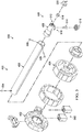
- View 500 is an exploded view of high-volume low-pressure end effector 400 of Figure 4 .
- valves 502 are visible.
- pins 504 connecting connection arm 406 to attachment bracket 404 are visible. Pins 504 are configured to provide a desired alignment of spray head 408 within high-volume low-pressure end effector 400.
- Pins 504 may have any desirable quantity of pins. In some illustrative examples, pins 504 have a minimal quantity of pins.
- pins 506 connecting spray head 408 to connection arm 406 are visible.
- Pins 506 are configured to provide a desired alignment of spray head 408 within high-volume low-pressure end effector 400.
- Pins 506 may have any desirable quantity of pins. In some illustrative examples, pins 506 have a minimal quantity of pins.
- number of outlets 508 of spray head 408 is visible.
- number of outlets 508 includes first outlet 510 and second outlet 512.
- high-volume low-pressure end effector 400 also has a respective nozzle and a respective aircap for each of first outlet 510 and second outlet 512.
- Nozzle 514 and aircap 516 are associated with first outlet 510.
- Nozzle 518 and aircap 520 are associated with second outlet 512.
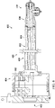
- View 600 is a cross-sectional view of high-volume low-pressure end effector 400 of Figure 4 .
- valves 502 controlling the flow of fluid and air through high-volume low-pressure end effector 400 are visible within attachment bracket 404.
- Valves 502 control the flow of fluid and air through flexible conduits 602 running through housing 604 of connection arm 406.
- Spray head 408 has integral channels 606 configured to receive air and fluid from flexible conduits 602 and deliver the air and fluid to number of outlets 508.
- View 700 is an isometric view of connection arm 406 of Figure 4 .
- Connection arm 406 comprises housing 604 with flexible conduits 602 running through housing 604. As depicted, housing 604 is hollow. In some illustrative examples, housing 604 is a hollow metal housing.
- Flexible conduits 602 will be connected to fittings 1102 of spray head 408 depicted in Figure 11 .
- the quantity of flexible conduits 602 is the same as quantity of fittings 1102.
- the quantity of flexible conduits 602 may be greater than fittings of a spray head.
- flexible conduits 602 comprises six conduits.
- Flexible conduits 602 includes three conduits for each outlet of spray head 408.
- Flexible conduits 602 comprises one fluid conduit and two air conduits for each outlet of spray head 408.
- spray head 408 may include a different quantity of outlets.
- spray head 408 may have more than two outlets.
- the quantity of flexible conduits 602 will be greater than six.
- the quantity of flexible conduits 602 will be nine flexible conduits.
- spray head 408 may only have one outlet. In this illustrative example, quantity of flexible conduits 602 may be three.
- FIG. 8 an illustration of a front view of a connection arm is depicted in accordance with an illustrative embodiment.
- View 800 is a view from direction 8 of Figure 7 .
- View 800 is a front view of connection arm 406 of Figure 4 .
- View 800 is a view of end 802 of connection arm 406 that will connect to spray head 408.
- ends 804 of flexible conduits 602 are visible. Ends 804 will be connected to fittings (not depicted) of spray head 408 of Figure 4 .
- View 900 is a view from direction 9 of Figure 7 .
- View 900 is a back view of connection arm 406 of Figure 4 .
- View 900 is a view of end 902 of connection arm 406 that will connect to attachment bracket 404.
- View 1000 is a cross-sectional view of connection arm 406 of Figure 4 .
- View 1100 is a cross-sectional view of connection arm 406 connected to spray head 408 of Figure 4 .
- ends 804 of flexible conduits 602 are connected to fittings 1102 of spray head 408.
- Fittings 1102 form connections between flexible conduits 602 and integral channels 606.
- View 1200 is an isometric view of spray head 408 separate from the remainder of high-volume low-pressure end effector 400.
- aircap 516 is secured to first outlet 510 of spray head 408. Aircap 516 seals nozzle 514 of Figure 5 within first outlet 510. Aircap 520 is secured to second outlet 512 of spray head 408. Aircap 520 seals nozzle 518 of Figure 5 within second outlet 512.
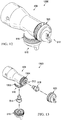
- View 1300 is an exploded view of spray head 408 and associated nozzles and aircaps.
- View 1300 is a closer exploded view of spray head 408, aircaps, and nozzles of Figure 5 .
- threads 1302 of first outlet 510 are visible.
- aircap 516 is secured to first outlet 510 using threads 1302.
- threads 1304 of second outlet 512 are visible.
- aircap 520 is secured to second outlet 512 using threads 1304.
- View 1400 is a back isometric view of spray head 408 and associated nozzles, fittings, and aircaps.
- fittings 1102 comprise air fittings 1404 and fluid fittings 1406.
- Fluid fittings 1406 include fluid fitting 1408 providing fluid to first outlet 510 and fluid fitting 1410 providing fluid to second outlet 512.
- Air fittings 1404 include air fittings 1412 providing air to first outlet 510 and air fittings 1414 providing air to second outlet 512.
- Fittings 1102 will be connected to flexible conduits 602. As depicted, the quantity of fittings 1102 is the same as the quantity of flexible conduits 602. Each of flexible conduits 602 will connect to a respective fitting of fittings 1102.
- fittings 1102 comprises six fittings.
- Fittings 1102 includes three fittings for each outlet, one fluid fitting and two air fittings.
- Air fittings 1412 includes two air fittings.
- Air fittings 1414 includes two air fittings.
- spray head 408 may include a different quantity of fittings.
- spray head 408 may have more than two outlets.
- the quantity of fittings will be greater than six.
- the quantity of fittings will be nine fittings.
- spray head 408 may only have three fittings.
- View 1500 is an isometric view of spray head 408.
- first outlet 510 and second outlet 512 are visible. As can be seen in view 1500, first outlet 510 and second outlet 512 are directed at ninety degrees relative to each other.
- View 1600 is a cross-sectional view of spray head 408.
- View 1700 is a transparent view of spray head 408 of Figure 4 .
- the material of spray head 408 is transparent while the boundaries of integral channels 606 are solid.
- Spray head 408 is shown as only one non-limiting example of a physical implementation of spray head 208 of Figure 2 .
- Spray head 208 may have any desirable number of outlets. In some illustrative examples, spray head 208 may have only one outlet. In other illustrative examples, spray head 208 may have more than two outlets.
- integral channels 216 may have any desirable shape or path within spray head 208.
- Integral channels 606 are only one non-limiting example of integral channels that may be present within spray head 408. Integral channels 606 are only one non-limiting example of integral channels 216 of Figure 2 .
- Method 1800 may apply a fluid to at least one component of aircraft 100 of Figure 1 .
- Method 1800 may take place in manufacturing environment 200 of Figure 2 using high-volume low-pressure end effector 204.
- Method 1800 may take place in manufacturing environment 300 of Figure 3 .
- Method 1800 may be performed using high-volume low-pressure end effector 400 of Figures 4-17 .
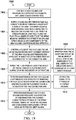
- Method 1800 supplies a fluid and air through flexible conduits running through a housing of a connection arm to a spray head with integral channels configured to receive the air and the fluid from the conduits and deliver the air and the fluid to a number of outlets of the spray head, wherein the connection arm and spray head are components of a high-volume low-pressure end effector (operation 1802 ) .
- Method 1800 sprays the fluid from at least one outlet of the number of outlets and onto surfaces of an enclosure of a structure (operation 1804 ). Afterwards, the method terminates.
- Method 1900 may apply a fluid to at least one component of aircraft 100 of Figure 1 .
- Method 1900 may take place in manufacturing environment 200 of Figure 2 using high-volume low-pressure end effector 204.
- Method 1900 may take place in manufacturing environment 300 of Figure 3 .
- Method 1900 may be performed using high-volume low-pressure end effector 400 of Figures 4-17 .
- Method 1900 connects a high-volume low-pressure end effector to a robotic arm using a quick-change tool ( 1902 ).
- Method 1900 supplies a fluid and air through flexible conduits running through a housing of a connection arm to a spray head with integral channels configured to receive the air and the fluid from the conduits and deliver the air and the fluid to a number of outlets of the spray head, wherein the connection arm and spray head are components of the high-volume low-pressure end effector (operation 1904 ).
- Method 1900 controls a flow of the fluid and the air using valves within an attachment bracket of the high-volume low-pressure end effector, wherein the attachment bracket is connected to the connection arm (operation 1906).
- Method 1900 sprays the fluid from at least one outlet of the number of outlets and onto surfaces of an enclosure of a structure (operation 1908 ).
- the fluid is sprayed from the at least one outlet of the number of outlets and onto the surfaces of the enclosure of the structure with a coverage of at least 90 percent (operation 1909 ).
- Method 1900 performs maintenance on the high-volume low-pressure end effector by removing the flexible conduits from the connection arm and placing replacement flexible conduits within the connection arm (operation 1910 ).
- performing maintenance further comprises attaching the conduits to fittings of the spray head (operation 1912 ).
- Method 1900 performs maintenance on the high-volume low-pressure end effector by disconnecting the flexible conduits from fittings of the spray head, removing the spray head, and connecting a replacement spray head to the connection arm (operation 1914 ). Afterwards, the method terminates.
- each block in the flowcharts or block diagrams may represent a module, a segment, a function, and/or a portion of an operation or step.
- the function or functions noted in the blocks may occur out of the order noted in the figures.
- two blocks shown in succession may be executed substantially concurrently, or the blocks may sometimes be performed in the reverse order, depending upon the functionality involved.
- other blocks may be added, in addition to the illustrated blocks, in a flowchart or block diagram.
- aircraft manufacturing and service method 2000 may be described in the context of aircraft manufacturing and service method 2000 as shown in Figure 20 and aircraft 2100 as shown in Figure 21 .
- Figure 20 an illustration of an aircraft manufacturing and service method is depicted in accordance with an illustrative embodiment.
- aircraft manufacturing and service method 2000 may include specification and design 2002 of aircraft 2100 in Figure 21 and material procurement 2004.
- aircraft 2100 During production, component and subassembly manufacturing 2006 and system integration 2008 of aircraft 2100 takes place. Thereafter, aircraft 2100 may go through certification and delivery 2010 in order to be placed in service 2012. While in service 2012 by a customer, aircraft 2100 is scheduled for routine maintenance and service 2014, which may include modification, reconfiguration, refurbishment, or other maintenance and service.
- Each of the processes of aircraft manufacturing and service method 2000 may be performed or carried out by a system integrator, a third party, and/or an operator.
- the operator may be a customer.
- a system integrator may include, without limitation, any number of aircraft manufacturers and major-system subcontractors
- a third party may include, without limitation, any number of vendors, subcontractors, and suppliers
- an operator may be an airline, a leasing company, a military entity, a service organization, and so on.
- aircraft 2100 is produced by aircraft manufacturing and service method 2000 of Figure 20 and may include airframe 2102 with plurality of systems 2104 and interior 2106.
- systems 2104 include one or more of propulsion system 2108, electrical system 2110, hydraulic system 2112, and environmental system 2114. Any number of other systems may be included.
- propulsion system 2108 includes one or more of propulsion system 2108, electrical system 2110, hydraulic system 2112, and environmental system 2114. Any number of other systems may be included.
- an aerospace example is shown, different illustrative embodiments may be applied to other industries, such as the automotive industry.
- Apparatuses and methods embodied herein may be employed during at least one of the stages of aircraft manufacturing and service method 2000.
- One or more illustrative embodiments may be used during at least one of component and subassembly manufacturing 2006, system integration 2008, or maintenance and service 2014 of Figure 20 .
- high-volume low-pressure end effector 204 of Figure 2 may be used during component and subassembly manufacturing 2006 to spray a coating onto portions of airframe 2102 of Figure 21 .
- High-volume low-pressure end effector 204 of Figure 2 may be used during component and subassembly manufacturing 2006 according to method 1800 of Figure 18 or method 1900 of Figure 19 .
- Fluid 202 may be sprayed onto components of aircraft 2100 using high-volume low-pressure end effector 204 of Figure 2 during system integration 2008.
- High-volume low-pressure end effector 204 may be used to spray a coating such as fluid 202 of Figure 2 on replacement components used during maintenance and service 2014 of Figure 20 .
- Structure 270 may be at least a component of airframe 2102.
- the illustrative examples provide an end of arm tooling with the ability to reach into the tight areas of a spar cavity and able to spray with both a zero degree spray tip as well as a ninety degree spray tip.
- the illustrative examples provide a system that is high-volume low-pressure (HVLP) compliant.
- HVLP high-volume low-pressure
- the illustrative examples provide a high-volume low-pressure end effector with significantly increased coverage over conventional end effectors.
- the coverage of the high-volume low-pressure end effector of the illustrative examples is increased due to an increased length of the connection arm of the high-volume low-pressure end effector compared to conventional end effectors.
- the coverage of the high-volume low-pressure end effector of the illustrative examples is also increased due to the high-volume low-pressure capacity of the illustrative examples.
- utilization of the robotic system having high-volume low-pressure end effector may also be higher than utilization of conventional end effectors.
- increasing utilization of automation the time to apply a coating to a structure is reduced. For example, increasing utilization of automation reduces the time to paint a wing.
- Increasing automation reduces manual application of coatings. Reducing manual application of coatings removes operators from an environment with airborne coatings. Reducing manual application of coatings reduces operator exposure to airborne coatings.
- the illustrative examples present a high-volume low-pressure end effector with a lower weight than conventional end effectors.
- Several of the components of the high-volume low-pressure end effector are hollow to reduce the weight of the end effector compared to conventional end effectors.
- the illustrative examples present a high-volume low-pressure end effector with better maintainability than conventional end effectors. Maintenance time is reduced by having fewer components. For example, high-volume low-pressure end effector does not have o-rings.
- At least one of maintenance time or maintenance cost may be reduced by having easily replicable and replaceable components.
- the use of flexible conduits allows for replacement of the conduits without replacing the whole of the connection arm. Not replacing the housing may result in less material waste and lower maintenance cost. By only replacing the flexible conduits during maintenance, the cost of maintenance may be reduced.
- the flexible conduits may be formed of inexpensive material.
- the flexible conduits may be commercially available.
Landscapes
- Engineering & Computer Science (AREA)
- Robotics (AREA)
- Manufacturing & Machinery (AREA)
- Transportation (AREA)
- Aviation & Aerospace Engineering (AREA)
- Mechanical Engineering (AREA)
- Nozzles (AREA)
- Spray Control Apparatus (AREA)
- Manipulator (AREA)
- Details Or Accessories Of Spraying Plant Or Apparatus (AREA)
Abstract
Description
- The present disclosure relates generally to performing manufacturing operations on components, and more specifically, to applying a fluid to a component. Still more particularly, the present disclosure relates to a high-volume low-pressure end effector configured to apply a fluid to a component.
- Spray applicators apply a fluid coating to a component by propelling and directing the fluid with air. A percentage of the fluid coating will become airborne within the manufacturing environment. Sprayed fluid coating not applied to a component may result in overspray. Overspray produces additional material cost. Overspray may also settle on surrounding structures in the manufacturing environment. The fraction of sprayed fluid coating applied to a component may be described as a coverage percentage.
- Applying a fluid coating inside tight areas of enclosures using spray end effectors may result in less than desirable coverage. For example, applying a fluid coating inside tight areas of enclosures may impact ability to access and spray adequately all surfaces using spray end effectors. Maneuvering spray end effectors may be undesirably difficult within tight areas of enclosures.
- Manually applying a fluid coating inside tight areas of enclosures may take an undesirably large amount of time. Manually applying a fluid coating inside tight areas of enclosures may take an undesirably large number of human operators. Manually applying a fluid coating using human operators may cause an undesirable amount of exposure to the fluid coating or components of the fluid coating for the human operators.
- Therefore, it would be desirable to have a method and apparatus that take into account at least some of the issues discussed above, as well as other possible issues. For example, it would be desirable to reduce the amount of overspray in a coating system for tight areas of enclosures. Also, it would be desirable to reduce the amount of airborne fluid within a manufacturing environment when applying a coating to tight areas of enclosures. It would be desirable to provide an apparatus to increase the coverage of a coating within tight areas of enclosures.
- An illustrative embodiment of the present disclosure provides a high-volume low-pressure end effector. The high-volume low-pressure end effector comprises a connection arm and a spray head. The connection arm comprises a housing with flexible conduits running through the housing. The spray head has integral channels configured to receive air and a fluid from the conduits and deliver the air and the fluid to a number of outlets.
- Another illustrative embodiment of the present disclosure provides a method. A fluid and air are supplied through flexible conduits running through a housing of a connection arm to a spray head with integral channels configured to receive the air and the fluid from the conduits and deliver the air and the fluid to a number of outlets of the spray head, wherein the connection arm and spray head are components of a high-volume low-pressure end effector. The fluid is sprayed from at least one outlet of the number of outlets and onto surfaces of an enclosure of a structure with a total coverage of at least 90 percent.
- A further illustrative embodiment of the present disclosure provides a high-volume low-pressure end effector. The high-volume low-pressure end effector comprises an attachment bracket, a connection arm, fittings, and a spray head. The attachment bracket covers valves for air and fluid. The connection arm comprises a hollow metal housing with flexible conduits running through the housing. The flexible conduits carry the air and the fluid. The fittings connect the flexible conduits to integral channels within a spray head. The spray head has integral channels delivering fluid and air to a number of outlets.
- The features and functions can be achieved independently in various embodiments of the present disclosure or may be combined in yet other embodiments in which further details can be seen with reference to the following description and drawings.
- The novel features believed characteristic of the illustrative embodiments are set forth in the appended claims. The illustrative embodiments, however, as well as a preferred mode of use, further objectives and features thereof, will best be understood by reference to the following detailed description of an illustrative embodiment of the present disclosure when read in conjunction with the accompanying drawings, wherein:
-
Figure 1 is an illustration of an aircraft in which an illustrative embodiment may be implemented; -
Figure 2 is an illustration of a block diagram of a manufacturing environment in accordance with an illustrative embodiment; -
Figure 3 is an illustration of a manufacturing environment in accordance with an illustrative embodiment; -
Figure 4 is an illustration of an isometric view of a high-volume low-pressure end effector in accordance with an illustrative embodiment; -
Figure 5 is an illustration of an exploded view of a high-volume low-pressure end effector in accordance with an illustrative embodiment; -
Figure 6 is an illustration of a cross-sectional view of a high-volume low-pressure end effector in accordance with an illustrative embodiment; -
Figure 7 is an illustration of an isometric view of a connection arm in accordance with an illustrative embodiment; -
Figure 8 is an illustration of a front view of a connection arm in accordance with an illustrative embodiment; -
Figure 9 is an illustration of a back view of a connection arm in accordance with an illustrative embodiment; -
Figure 10 is an illustration of a cross-sectional view of a connection arm in accordance with an illustrative embodiment; -
Figure 11 is an illustration of a cross-sectional view of a connection arm connected to a spray head in accordance with an illustrative embodiment; -
Figure 12 is an illustration of an isometric view of a spray head with nozzles and aircaps in accordance with an illustrative embodiment; -
Figure 13 is an illustration of an exploded view of a spray head with nozzles and aircaps in accordance with an illustrative embodiment; -
Figure 14 is an illustration of a back isometric view of a spray head with fittings in accordance with an illustrative embodiment; -
Figure 15 is an illustration of an isometric view of a spray head in accordance with an illustrative embodiment; -
Figure 16 is an illustration of a cross-sectional view of a spray head in accordance with an illustrative embodiment; -
Figure 17 is an illustration of a partially transparent view of a spray head in accordance with an illustrative embodiment; -
Figure 18 is an illustration of a flowchart of a method for applying a fluid to surfaces of an enclosure of a structure in accordance with an illustrative embodiment; -
Figure 19 is an illustration of a flowchart of a method for applying a fluid to surfaces of an enclosure of a structure in accordance with an illustrative embodiment; -
Figure 20 is an illustration of an aircraft manufacturing and service method in the form of a block diagram in accordance with an illustrative embodiment; and -
Figure 21 is an illustration of an aircraft in the form of a block diagram in which an illustrative embodiment may be implemented. - The illustrative embodiments recognize and take into account one or more different considerations. For example, the illustrative embodiments recognize and take into account that spar cavities are large enclosures with tight areas for coating coverage.
- The illustrative embodiments also recognize and take into account that conventional end effectors provide a low effective coverage of the spar cavities. The illustrative embodiments recognize and take into account that some conventional end effectors provide approximately 20 percent coverage within spar cavities.
- The illustrative embodiments recognize and take into account that low coverage leads to low utilization of the robotic system. The illustrative embodiments recognize and take into account that the low coverage leads to increased flow time. The illustrative embodiments recognize and take into account that low coverage may result in a large amount of manual touch-up.
- The illustrative embodiments recognize and take into account that many available spray paints, pigments, and other coatings contain hexavalent chromium. The illustrative embodiments recognize and take into account that minimizing human operator exposure to hexavalent chromium is desirable. The illustrative embodiments thus recognize and take into account that automating application of paints, pigments, and other coatings is desirable.
- The illustrative embodiments recognize and take into account that some conventional end effectors are made from machined aluminum. The illustrative embodiments recognize and take into account that conventional end effectors with machined aluminum blocks are heavier than robotic arm operating payload standards. The illustrative examples recognize and take into account that because some conventional end effectors are mostly machined billet aluminum, components of these end effector may be undesirably difficult or expensive to find and replace.
- With reference now to the figures, and in particular, with reference to
Figure 1 , an illustration of an aircraft is depicted in accordance with an illustrative embodiment. In this illustrative example,aircraft 100 haswing 102 andwing 104 attached tobody 106.Aircraft 100 includesengine 108 attached towing 102 andengine 110 attached towing 104. -
Body 106 hastail section 112.Horizontal stabilizer 114,horizontal stabilizer 116, andvertical stabilizer 118 are attached totail section 112 ofbody 106. -
Aircraft 100 is an example of an aircraft in which components coated using a high-volume low-pressure end effector may be implemented in accordance with an illustrative embodiment. For example, a high-volume low-pressure end effector may be used to apply coatings within wing spar cavities of at least one ofwing 102 orwing 104. - As used herein, the phrase "at least one of," when used with a list of items, means different combinations of one or more of the listed items may be used, and only one of each item in the list may be needed. In other words, "at least one of" means any combination of items and number of items may be used from the list, but not all of the items in the list are required. The item may be a particular object, a thing, or a category.
- For example, "at least one of item A, item B, or item C" may include, without limitation, item A, item A and item B, or item B. This example also may include item A, item B, and item C, or item B and item C. Of course, any combination of these items may be present. In other examples, "at least one of" may be, for example, without limitation, two of item A, one of item B, and ten of item C; four of item B and seven of item C; or other suitable combinations.
- This illustration of
aircraft 100 is provided for the purposes of illustrating one environment in which different illustrative embodiments may be implemented. The illustration ofaircraft 100 inFigure 1 is not meant to imply architectural limitations as to the manner in which different illustrative embodiments may be implemented. For example,aircraft 100 is shown as a commercial passenger aircraft. The different illustrative embodiments may be applied to other types of aircraft, such as a private passenger aircraft, rotorcraft, or other suitable types of aircraft. - Although the illustrative examples for an illustrative embodiment are described with respect to an aircraft, the illustrative embodiments may be applied to other types of structures. The structure may be, for example, a mobile structure, a stationary structure, a land-based structure, an aquatic-based structure, or a space-based structure. More specifically, the structure may be a surface ship, a tank, a personnel carrier, a train, a spacecraft, a space station, a satellite, a submarine, a manufacturing facility, a building, or other suitable types of structures.
- Turning now to
Figure 2 , an illustration of a block diagram of a manufacturing environment is depicted in accordance with an illustrative embodiment.Manufacturing environment 200 is an illustrative example of an environment in which components ofaircraft 100 may be processed. For example, fluid 202 may be applied to components ofaircraft 100 using high-volume low-pressure end effector 204 inmanufacturing environment 200. - High-volume low-
pressure end effector 204 comprisesconnection arm 206 andspray head 208.Connection arm 206 compriseshousing 210 with flexible 212conduits 214 running throughhousing 210.Spray head 208 hasintegral channels 216 configured to receiveair 218 and fluid 202 fromconduits 214 and deliverair 218 and fluid 202 to number ofoutlets 220. - As used herein, a "number of items" means one or more items. For example, number of
outlets 220 has one or more outlets. - In some illustrative examples, number of
outlets 220 comprisesfirst outlet 222 andsecond outlet 224 connected tointegral channels 216.First outlet 222 andsecond outlet 224 may have any desirable orientation relative to each other.First outlet 222 andsecond outlet 224 may be positioned anywhere from approximately zero degrees to approximately one hundred eighty degrees relative to each other. In some illustrative examples,first outlet 222 andsecond outlet 224 are pointed ninety degrees relative to each other. In other illustrative examples,first outlet 222 andsecond outlet 224 are pointed approximately one hundred eighty degrees relative to each other. - High-volume low-
pressure end effector 204 comprises a respective nozzle and aircap for each offirst outlet 222 andsecond outlet 224. As depicted,nozzle 226 andaircap 228 are associated withfirst outlet 222.Nozzle 230 andaircap 232 are associated withsecond outlet 224. In some illustrative examples, high-volume low-pressure end effector 204 comprises a respective aircap threaded on to each of number ofoutlets 220, wherein each respective aircap encloses a respective nozzle within each of number ofoutlets 220. -
Nozzle 226 andaircap 228 enable high-volume low-pressure application offluid 202.Nozzle 226 pressurizes fluid 202 and distributes the atomized fluid toaircap 228.Aircap 228 allows pass-through offluid 202 and distributes the atomized fluid tomanufacturing environment 200.Nozzle 226 andaircap 228 enable high-volume low-pressure spray offluid 202 fromfirst outlet 222. -
Nozzle 230 andaircap 232 enable high-volume low-pressure application offluid 202.Nozzle 230 pressurizes fluid 202 and distributes the pressurized fluid toaircap 232.Aircap 232 allows pass-through offluid 202 and distributes the atomized fluid tomanufacturing environment 200.Nozzle 230 andaircap 232 enable high-volume low-pressure spray offluid 202 fromsecond outlet 224. - A combination of
aircap 228 andspray head 208 holds and sealsnozzle 226 withinfirst outlet 222. In some illustrative examples,aircap 228 is threaded ontospray head 208 to sealaircap 228 againstspray head 208. In this illustrative example, additional sealing components such as o-rings or other sealing components are not used to sealaircap 228 tospray head 208. By not using additional sealing components,weight 234 of high-volume low-pressure end effector 204 may be reduced. By not using additional sealing components, maintenance time of high-volume low-pressure end effector 204 may be reduced. - A combination of
aircap 232 andspray head 208 holds and sealsnozzle 230 withinsecond outlet 224. In some illustrative examples,aircap 232 is threaded ontospray head 208 to sealaircap 232 againstspray head 208. In this illustrative example, additional sealing components such as o-rings or other sealing components are not used to sealaircap 232 tospray head 208. -
Integral channels 216 distributeair 218 and fluid 202 to the nozzles associated withspray head 208.Integral channels 216 distributeair 218 and fluid 202 tonozzle 226 andnozzle 230. -
Spray head 208 is formed of any desirable material.Material 236 is selected to be compatible with use offluid 202. When fluid 202 is paint,material 236 is selected to be paint compatible. For example,material 236 is selected to not be reactive tofluid 202 or to solvents used to remove fluid 202 fromspray head 208. In one illustrative example,material 236 is stainless steel. - In some illustrative examples,
spray head 208 is monolithic 238. Whenspray head 208 is monolithic 238,spray head 208 is one indivisible component. -
Spray head 208 may be manufactured using any desirable method. In some illustrative examples,spray head 208 is formed using an additive manufacturing method. In some other illustrative examples,spray head 208 is formed by machining. In yet other illustrative examples,spray head 208 may be formed by molding or other manufacturing techniques. In some illustrative examples, a manufacturing technique for creatingspray head 208 is selected based on at least one of a desirable manufacturing time, a desirable manufacturing cost, a desirable manufacturing accuracy, or any other manufacturing factors. -
Integral channels 216 extend fromfirst end 240 ofspray head 208 towardssecond end 242 ofspray head 208.First end 240 is oppositesecond end 242 ofspray head 208.Integral channels 216 have any desirable shape and size to deliverair 218 and fluid 202 to number ofoutlets 220. -
Fittings 244 connectconduits 214 inconnection arm 206 tointegral channels 216 ofspray head 208.Fittings 244 are associated withinlets 246 ofintegral channels 216 atfirst end 240 ofspray head 208.Fittings 244 are physically connected tointegral channels 216 using any desirable type of connection. In some illustrative examples,fittings 244 are threaded. In these illustrative examples, torque is applied to securefittings 244 tospray head 208. - In high-volume low-
pressure end effector 204,fittings 244 comprise number ofair fittings 248 and number offluid fittings 250. In some illustrative examples, number ofair fittings 248 comprises two air fittings per outlet, and wherein number offluid fittings 250 comprises one fluid fitting per outlet. In these illustrative examples, a first air fitting suppliesair 218 to atomize fluid 202 exiting the respective nozzle. In these illustrative examples, a second air fitting suppliesair 218 to form shaping air streams. The second air fitting provides shaping air streams to control application offluid 202 and evenly distributefluid 202. - The quantity of
conduits 214 is any desirable quantity. In some illustrative examples, the quantity ofconduits 214 is equal to the quantity offittings 244. - In some illustrative examples, the quantity of
conduits 214 is affected by the quantity of outlets in number ofoutlets 220. For example, each outlet of number ofoutlets 220 will receiveair 218 andfluid 202. The quantity ofconduits 214 will be sufficient to provideair 218 and fluid 202 to each outlet of number ofoutlets 220. - When number of
outlets 220 is one outlet,conduits 214 contains at least one conduit withfluid 202 and at least two conduits withair 218. When number ofoutlets 220 is two outlets,conduits 214 contains at least two conduits withfluid 202 and at least four conduits withair 218. -
Spray head 208 is replaceable. In some illustrative examples,spray head 208 may be replaced with a spray head with a different quantity of outlets. In these illustrative examples,conduits 214 may remain inhousing 210 afterspray head 208 is replaced. In these illustrative examples,conduits 214 may contain a larger quantity of conduits than a quantity of outlets or a quantity of nozzles in the replacement spray head. -
First end 240 ofspray head 208 is connected toconnection arm 206.Spray head 208 is connected toconnection arm 206 usingfasteners 252. In some illustrative examples, the connection betweenconnection arm 206 andspray head 208 has a minimal quantity offasteners 252. A minimal quantity offasteners 252 may reduceweight 234 of high-volume low-pressure end effector 204. A minimal quantity offasteners 252 may also reduce maintenance time for high-volume low-pressure end effector 204.Fasteners 252 are selected to not extend fromconnection arm 206 an undesirable amount. - In some illustrative examples,
first end 240 is inserted intohousing 210 prior to connectingspray head 208 andconnection arm 206. In some illustrative examples,spray head 208 reduces in cross-sectional area moving fromfirst end 240 tosecond end 242. By reducing in cross-sectional area,spray head 208 may maneuver within tight areas more easily. -
Connection arm 206 hashousing 210.Housing 210 hascross-section 254.Cross-section 254 is selected to accommodateconduits 214. In some illustrative examples,cross-section 254 is selected to reduce chances of collision ofhousing 210 during rotation. - In some illustrative examples,
cross-section 254 is circular 256. In these illustrative examples,housing 210 has circular 256cross-section 254. Whencross-section 254 is circular 256, deflection is lower than for cross-sections with sharp corners. - In some illustrative examples,
housing 210 is hollow 257 to accommodateconduits 214. In some illustrative examples,housing 210 is hollow 257 to reduceweight 234 of high-volume low-pressure end effector 204. -
Connection arm 206 is formed ofmaterial 258.Connection arm 206 may be formed of any desirable material. In some illustrative examples,material 258 ofhousing 210 is selected based on at least one of strength, rigidity, or weight. In some illustrative examples,material 258 ofhousing 210 ismetal 259. In some illustrative examples,housing 210 is hollow 257metal 259housing 210. In one illustrative example,housing 210 may be formed of aluminum. -
Attachment bracket 260 attachesconnection arm 206 toconnector 262.Attachment bracket 260 is designed to reduceweight 234 of high-volume low-pressure end effector 204.Attachment bracket 260 may take the form of a number of hollow components fastened together. -
Valves 266 control the flow offluid 202 andair 218 through high-volume low-pressure end effector 204. In this illustrative example,valves 266 are positioned withinattachment bracket 260. By positioningvalves 266 nearrobotic arm 268, movement ofrobotic arm 268 is easier. Positioningvalves 266 withinattachment bracket 260 creates a reduced moment of inertia forrobotic arm 268 and high-volume low-pressure end effector 204. -
Connector 262 connects high-volume low-pressure end effector 204 torobotic arm 268. Whenconnector 262 is quick-change tool 264, high-volume low-pressure end effector 204 may be quickly removed fromrobotic arm 268.Conduits 269 withinconnector 262pass fluid 202 andair 218 throughconnector 262. -
Robotic arm 268 maneuvers high-volume low-pressure end effector 204 withinmanufacturing environment 200.Robotic arm 268 is used to maneuver high-volume low-pressure end effector 204 tospray fluid 202 onto portions ofstructure 270. -
Structure 270 hasenclosure 272.Robotic arm 268 maneuvers high-volume low-pressure end effector 204 withinenclosure 272 to apply fluid 202 toenclosure 272 withcoverage 274.Coverage 274 is within a desirable range. In some illustrative examples,coverage 274 is desirably above 80 percent. In some illustrative examples,coverage 274 is desirably above 90 percent. In some illustrative examples,coverage 274 may be about 95 percent. - In one illustrative example, high-volume low-
pressure end effector 204 comprisesattachment bracket 260 containingvalves 266 forair 218 andfluid 202;connection arm 206 comprising hollow 257metal 259housing 210 with flexible 212conduits 214 running throughhousing 210; flexible 212conduits 214 carryingair 218 andfluid 202;fittings 244 connecting flexible 212conduits 214 tointegral channels 216 withinspray head 208; andspray head 208 havingintegral channels 216 deliveringfluid 202 andair 218 to number ofoutlets 220. - The illustration of
manufacturing environment 200 inFigure 2 is not meant to imply physical or architectural limitations to the manner in which an illustrative embodiment may be implemented. Other components in addition to, or in place of, the ones illustrated may be used. Some components may be unnecessary. Also, the blocks are presented to illustrate some functional components. One or more of these blocks may be combined, divided, or combined and divided into different blocks when implemented in an illustrative embodiment. - Number of
outlets 220 ofspray head 208 has any desirable quantity of outlets. In some illustrative examples, number ofoutlets 220 may have only one outlet. In other illustrative examples, number ofoutlets 220 may have more than two outlets. - Turning now to
Figure 3 , an illustration of a manufacturing environment is depicted in accordance with an illustrative embodiment.Manufacturing environment 300 is a physical implementation ofmanufacturing environment 200 ofFigure 2 .Wing 302 inmanufacturing environment 300 may be one ofwing 102 orwing 104 ofaircraft 100 inFigure 1 . - As depicted, high-volume low-
pressure end effector 304 is connected torobotic arm 306. High-volume low-pressure end effector 304 is a physical implementation of high-volume low-pressure end effector 204 ofFigure 2 . High-volume low-pressure end effector 304 is positioned withinwing spar cavity 308 ofwing 302. During operation, high-volume low-pressure end effector 304 will be maneuvered byrobotic arm 306 to apply a coating, such as paint or other desirable coating, towing spar cavity 308. - Turning now to
Figure 4 , an illustration of an isometric view of a high-volume low-pressure end effector is depicted in accordance with an illustrative embodiment. High-volume low-pressure end effector 400 is a physical implementation of high-volume low-pressure end effector 204 ofFigure 2 . High-volume low-pressure end effector 400 may be used to apply a coating to a component ofaircraft 100 ofFigure 1 . High-volume low-pressure end effector 400 may be a physical implementation of high-volume low-pressure end effector 304 ofFigure 3 . - High-volume low-
pressure end effector 400 comprisesconnector 402,attachment bracket 404,connection arm 406, andspray head 408.Connector 402 is used to connect high-volume low-pressure end effector 400 to a robotic arm, such asrobotic arm 306 ofFigure 3 . In some illustrative examples,connector 402 is a quick-change connector. -
Attachment bracket 404 attachesconnection arm 406 toconnector 402. In some illustrative examples,attachment bracket 404 encompasses valves to control spray of fluid from high-volume low-pressure end effector 400. -
Connection arm 406 lengthens high-volume low-pressure end effector 400.Connection arm 406 has a desirable length to positionspray head 408 within tight areas of enclosures. A cross-section ofconnection arm 406 is configured to maneuverspray head 408 within tight areas of enclosures. - Turning now to
Figure 5 , an illustration of an exploded view of a high-volume low-pressure end effector is depicted in accordance with an illustrative embodiment. View 500 is an exploded view of high-volume low-pressure end effector 400 ofFigure 4 . Inview 500,valves 502 are visible. - In
view 500, pins 504 connectingconnection arm 406 toattachment bracket 404 are visible.Pins 504 are configured to provide a desired alignment ofspray head 408 within high-volume low-pressure end effector 400. -
Pins 504 may have any desirable quantity of pins. In some illustrative examples, pins 504 have a minimal quantity of pins. - In
view 500, pins 506 connectingspray head 408 toconnection arm 406 are visible.Pins 506 are configured to provide a desired alignment ofspray head 408 within high-volume low-pressure end effector 400.Pins 506 may have any desirable quantity of pins. In some illustrative examples, pins 506 have a minimal quantity of pins. - In
view 500, number ofoutlets 508 ofspray head 408 is visible. In this illustrative example, number ofoutlets 508 includesfirst outlet 510 andsecond outlet 512. - As depicted, high-volume low-
pressure end effector 400 also has a respective nozzle and a respective aircap for each offirst outlet 510 andsecond outlet 512.Nozzle 514 andaircap 516 are associated withfirst outlet 510.Nozzle 518 andaircap 520 are associated withsecond outlet 512. - Turning now to
Figure 6 , an illustration of a cross-sectional view of a high-volume low-pressure end effector is depicted in accordance with an illustrative embodiment. View 600 is a cross-sectional view of high-volume low-pressure end effector 400 ofFigure 4 . - In
view 600,valves 502 controlling the flow of fluid and air through high-volume low-pressure end effector 400 are visible withinattachment bracket 404.Valves 502 control the flow of fluid and air throughflexible conduits 602 running throughhousing 604 ofconnection arm 406.Spray head 408 hasintegral channels 606 configured to receive air and fluid fromflexible conduits 602 and deliver the air and fluid to number ofoutlets 508. - Turning now to
Figure 7 , an illustration of an isometric view of a connection arm is depicted in accordance with an illustrative embodiment. View 700 is an isometric view ofconnection arm 406 ofFigure 4 . -
Connection arm 406 compriseshousing 604 withflexible conduits 602 running throughhousing 604. As depicted,housing 604 is hollow. In some illustrative examples,housing 604 is a hollow metal housing. -
Flexible conduits 602 will be connected tofittings 1102 ofspray head 408 depicted inFigure 11 . In this illustrative example, the quantity offlexible conduits 602 is the same as quantity offittings 1102. In some illustrative examples, when a spray head other thanspray head 408 is used, the quantity offlexible conduits 602 may be greater than fittings of a spray head. - As depicted,
flexible conduits 602 comprises six conduits.Flexible conduits 602 includes three conduits for each outlet ofspray head 408.Flexible conduits 602 comprises one fluid conduit and two air conduits for each outlet ofspray head 408. - In other illustrative examples,
spray head 408 may include a different quantity of outlets. For example,spray head 408 may have more than two outlets. In some illustrative examples, whenspray head 408 has more than two outlets, the quantity offlexible conduits 602 will be greater than six. In one illustrative example, whenspray head 408 has three outlets, the quantity offlexible conduits 602 will be nine flexible conduits. Whenspray head 408 has less than two outlets, the quantity offlexible conduits 602 may be less than six. In some illustrative examples,spray head 408 may only have one outlet. In this illustrative example, quantity offlexible conduits 602 may be three. - Turning now to
Figure 8 , an illustration of a front view of a connection arm is depicted in accordance with an illustrative embodiment. View 800 is a view fromdirection 8 ofFigure 7 . View 800 is a front view ofconnection arm 406 ofFigure 4 . - View 800 is a view of
end 802 ofconnection arm 406 that will connect to sprayhead 408. Inview 800, ends 804 offlexible conduits 602 are visible.Ends 804 will be connected to fittings (not depicted) ofspray head 408 ofFigure 4 . - Turning now to
Figure 9 , an illustration of a back view of a connection arm is depicted in accordance with an illustrative embodiment. View 900 is a view fromdirection 9 ofFigure 7 . View 900 is a back view ofconnection arm 406 ofFigure 4 . View 900 is a view ofend 902 ofconnection arm 406 that will connect toattachment bracket 404. - Turning now to
Figure 10 , an illustration of a cross-sectional view of a connection arm is depicted in accordance with an illustrative embodiment.View 1000 is a cross-sectional view ofconnection arm 406 ofFigure 4 . - Turning now to
Figure 11 , an illustration of a cross-sectional view of a connection arm connected to a spray head is depicted in accordance with an illustrative embodiment.View 1100 is a cross-sectional view ofconnection arm 406 connected to sprayhead 408 ofFigure 4 . - In
view 1100, ends 804 offlexible conduits 602 are connected tofittings 1102 ofspray head 408.Fittings 1102 form connections betweenflexible conduits 602 andintegral channels 606. - Turning now to
Figure 12 , an illustration of an isometric view of a spray head with nozzles and aircaps is depicted in accordance with an illustrative embodiment.View 1200 is an isometric view ofspray head 408 separate from the remainder of high-volume low-pressure end effector 400. - In
view 1200,aircap 516 is secured tofirst outlet 510 ofspray head 408.Aircap 516seals nozzle 514 ofFigure 5 withinfirst outlet 510.Aircap 520 is secured tosecond outlet 512 ofspray head 408.Aircap 520seals nozzle 518 ofFigure 5 withinsecond outlet 512. - Turning now to
Figure 13 , an illustration of an exploded view of a spray head with nozzles and aircaps is depicted in accordance with an illustrative embodiment.View 1300 is an exploded view ofspray head 408 and associated nozzles and aircaps. -
View 1300 is a closer exploded view ofspray head 408, aircaps, and nozzles ofFigure 5 . Inview 1300,threads 1302 offirst outlet 510 are visible. To securenozzle 514 withinfirst outlet 510,aircap 516 is secured tofirst outlet 510 usingthreads 1302. Inview 1300,threads 1304 ofsecond outlet 512 are visible. To securenozzle 518 withinsecond outlet 512,aircap 520 is secured tosecond outlet 512 usingthreads 1304. - Turning now to
Figure 14 , an illustration of a back isometric view of a spray head with fittings is depicted in accordance with an illustrative embodiment.View 1400 is a back isometric view ofspray head 408 and associated nozzles, fittings, and aircaps. - As depicted,
fittings 1102 compriseair fittings 1404 andfluid fittings 1406.Fluid fittings 1406 includefluid fitting 1408 providing fluid tofirst outlet 510 and fluid fitting 1410 providing fluid tosecond outlet 512.Air fittings 1404 include air fittings 1412 providing air tofirst outlet 510 andair fittings 1414 providing air tosecond outlet 512. -
Fittings 1102 will be connected toflexible conduits 602. As depicted, the quantity offittings 1102 is the same as the quantity offlexible conduits 602. Each offlexible conduits 602 will connect to a respective fitting offittings 1102. - As depicted,
fittings 1102 comprises six fittings.Fittings 1102 includes three fittings for each outlet, one fluid fitting and two air fittings. Air fittings 1412 includes two air fittings.Air fittings 1414 includes two air fittings. - In other illustrative examples,
spray head 408 may include a different quantity of fittings. For example,spray head 408 may have more than two outlets. In some illustrative examples, whenspray head 408 has more than two outlets, the quantity of fittings will be greater than six. In one illustrative example, whenspray head 408 has three outlets, the quantity of fittings will be nine fittings. Whenspray head 408 has less than two outlets, the quantity of fittings will be less than six. For example, in some illustrative examples,spray head 408 may only have three fittings. - Turning now to
Figure 15 , an illustration of an isometric view of a spray head is depicted in accordance with an illustrative embodiment.View 1500 is an isometric view ofspray head 408. - In
view 1500,first outlet 510 andsecond outlet 512 are visible. As can be seen inview 1500,first outlet 510 andsecond outlet 512 are directed at ninety degrees relative to each other. - Turning now to
Figure 16 , an illustration of a cross-sectional view of a spray head is depicted in accordance with an illustrative embodiment.View 1600 is a cross-sectional view ofspray head 408. - Turning now to
Figure 17 , an illustration of a partially transparent view of a spray head is depicted in accordance with an illustrative embodiment.View 1700 is a transparent view ofspray head 408 ofFigure 4 . - In
view 1700, the material ofspray head 408 is transparent while the boundaries ofintegral channels 606 are solid. -
Spray head 408 is shown as only one non-limiting example of a physical implementation ofspray head 208 ofFigure 2 .Spray head 208 may have any desirable number of outlets. In some illustrative examples,spray head 208 may have only one outlet. In other illustrative examples,spray head 208 may have more than two outlets. - Further,
integral channels 216 may have any desirable shape or path withinspray head 208.Integral channels 606 are only one non-limiting example of integral channels that may be present withinspray head 408.Integral channels 606 are only one non-limiting example ofintegral channels 216 ofFigure 2 . - The different components shown in
Figures 1 and3 -17 may be combined with components inFigure 2 , used with components inFigure 2 , or a combination of the two. Additionally, some of the components inFigures 1 and3 -17 may be illustrative examples of how components shown in block form inFigure 2 may be implemented as physical structures. - Turning now to
Figure 18 , an illustration of a flowchart of a method for applying a fluid to surfaces of an enclosure of a structure is depicted in accordance with an illustrative embodiment.Method 1800 may apply a fluid to at least one component ofaircraft 100 ofFigure 1 .Method 1800 may take place inmanufacturing environment 200 ofFigure 2 using high-volume low-pressure end effector 204.Method 1800 may take place inmanufacturing environment 300 ofFigure 3 .Method 1800 may be performed using high-volume low-pressure end effector 400 ofFigures 4-17 . -
Method 1800 supplies a fluid and air through flexible conduits running through a housing of a connection arm to a spray head with integral channels configured to receive the air and the fluid from the conduits and deliver the air and the fluid to a number of outlets of the spray head, wherein the connection arm and spray head are components of a high-volume low-pressure end effector (operation 1802).Method 1800 sprays the fluid from at least one outlet of the number of outlets and onto surfaces of an enclosure of a structure (operation 1804). Afterwards, the method terminates. - Turning now to
Figure 19 , an illustration of a flowchart of a method for applying a fluid to surfaces of an enclosure of a structure is depicted in accordance with an illustrative embodiment.Method 1900 may apply a fluid to at least one component ofaircraft 100 ofFigure 1 .Method 1900 may take place inmanufacturing environment 200 ofFigure 2 using high-volume low-pressure end effector 204.Method 1900 may take place inmanufacturing environment 300 ofFigure 3 .Method 1900 may be performed using high-volume low-pressure end effector 400 ofFigures 4-17 . -
Method 1900 connects a high-volume low-pressure end effector to a robotic arm using a quick-change tool (1902).Method 1900 supplies a fluid and air through flexible conduits running through a housing of a connection arm to a spray head with integral channels configured to receive the air and the fluid from the conduits and deliver the air and the fluid to a number of outlets of the spray head, wherein the connection arm and spray head are components of the high-volume low-pressure end effector (operation 1904).Method 1900 controls a flow of the fluid and the air using valves within an attachment bracket of the high-volume low-pressure end effector, wherein the attachment bracket is connected to the connection arm (operation 1906).Method 1900 sprays the fluid from at least one outlet of the number of outlets and onto surfaces of an enclosure of a structure (operation 1908). In some illustrative examples, the fluid is sprayed from the at least one outlet of the number of outlets and onto the surfaces of the enclosure of the structure with a coverage of at least 90 percent (operation 1909). -
Method 1900 performs maintenance on the high-volume low-pressure end effector by removing the flexible conduits from the connection arm and placing replacement flexible conduits within the connection arm (operation 1910). In some illustrative examples, performing maintenance further comprises attaching the conduits to fittings of the spray head (operation 1912). -
Method 1900 performs maintenance on the high-volume low-pressure end effector by disconnecting the flexible conduits from fittings of the spray head, removing the spray head, and connecting a replacement spray head to the connection arm (operation 1914). Afterwards, the method terminates. - The flowcharts and block diagrams in the different depicted embodiments illustrate the architecture, functionality, and operation of some possible implementations of apparatus and methods in an illustrative embodiment. In this regard, each block in the flowcharts or block diagrams may represent a module, a segment, a function, and/or a portion of an operation or step.
- In some alternative implementations of an illustrative embodiment, the function or functions noted in the blocks may occur out of the order noted in the figures. For example, in some cases, two blocks shown in succession may be executed substantially concurrently, or the blocks may sometimes be performed in the reverse order, depending upon the functionality involved. Also, other blocks may be added, in addition to the illustrated blocks, in a flowchart or block diagram.
- Illustrative embodiments of the present disclosure may be described in the context of aircraft manufacturing and
service method 2000 as shown inFigure 20 andaircraft 2100 as shown inFigure 21 . Turning first toFigure 20 , an illustration of an aircraft manufacturing and service method is depicted in accordance with an illustrative embodiment. During pre-production, aircraft manufacturing andservice method 2000 may include specification anddesign 2002 ofaircraft 2100 inFigure 21 andmaterial procurement 2004. - During production, component and
subassembly manufacturing 2006 andsystem integration 2008 ofaircraft 2100 takes place. Thereafter,aircraft 2100 may go through certification anddelivery 2010 in order to be placed inservice 2012. While inservice 2012 by a customer,aircraft 2100 is scheduled for routine maintenance andservice 2014, which may include modification, reconfiguration, refurbishment, or other maintenance and service. - Each of the processes of aircraft manufacturing and
service method 2000 may be performed or carried out by a system integrator, a third party, and/or an operator. In these examples, the operator may be a customer. For the purposes of this description, a system integrator may include, without limitation, any number of aircraft manufacturers and major-system subcontractors; a third party may include, without limitation, any number of vendors, subcontractors, and suppliers; and an operator may be an airline, a leasing company, a military entity, a service organization, and so on. - With reference now to
Figure 21 , an illustration of an aircraft is depicted in which an illustrative embodiment may be implemented. In this example,aircraft 2100 is produced by aircraft manufacturing andservice method 2000 ofFigure 20 and may includeairframe 2102 with plurality ofsystems 2104 and interior 2106. Examples ofsystems 2104 include one or more ofpropulsion system 2108,electrical system 2110,hydraulic system 2112, andenvironmental system 2114. Any number of other systems may be included. Although an aerospace example is shown, different illustrative embodiments may be applied to other industries, such as the automotive industry. - Apparatuses and methods embodied herein may be employed during at least one of the stages of aircraft manufacturing and
service method 2000. - One or more illustrative embodiments may be used during at least one of component and
subassembly manufacturing 2006,system integration 2008, or maintenance andservice 2014 ofFigure 20 . For example, high-volume low-pressure end effector 204 ofFigure 2 may be used during component andsubassembly manufacturing 2006 to spray a coating onto portions ofairframe 2102 ofFigure 21 . High-volume low-pressure end effector 204 ofFigure 2 may be used during component andsubassembly manufacturing 2006 according tomethod 1800 ofFigure 18 ormethod 1900 ofFigure 19 . -
Fluid 202 may be sprayed onto components ofaircraft 2100 using high-volume low-pressure end effector 204 ofFigure 2 duringsystem integration 2008. High-volume low-pressure end effector 204 may be used to spray a coating such asfluid 202 ofFigure 2 on replacement components used during maintenance andservice 2014 ofFigure 20 .Structure 270 may be at least a component ofairframe 2102. - In some large enclosures, a long reach is required for high coverage. The illustrative examples provide an end of arm tooling with the ability to reach into the tight areas of a spar cavity and able to spray with both a zero degree spray tip as well as a ninety degree spray tip. The illustrative examples provide a system that is high-volume low-pressure (HVLP) compliant. The illustrative examples are safer for the manufacturing environment and operators than non-HVLP conventional end effectors.
- The illustrative examples provide a high-volume low-pressure end effector with significantly increased coverage over conventional end effectors. The coverage of the high-volume low-pressure end effector of the illustrative examples is increased due to an increased length of the connection arm of the high-volume low-pressure end effector compared to conventional end effectors. The coverage of the high-volume low-pressure end effector of the illustrative examples is also increased due to the high-volume low-pressure capacity of the illustrative examples.
- When coverage is increased, utilization of the robotic system having high-volume low-pressure end effector may also be higher than utilization of conventional end effectors. By increasing utilization of automation, the time to apply a coating to a structure is reduced. For example, increasing utilization of automation reduces the time to paint a wing. Increasing automation reduces manual application of coatings. Reducing manual application of coatings removes operators from an environment with airborne coatings. Reducing manual application of coatings reduces operator exposure to airborne coatings.
- The illustrative examples present a high-volume low-pressure end effector with a lower weight than conventional end effectors. Several of the components of the high-volume low-pressure end effector are hollow to reduce the weight of the end effector compared to conventional end effectors.
- The illustrative examples present a high-volume low-pressure end effector with better maintainability than conventional end effectors. Maintenance time is reduced by having fewer components. For example, high-volume low-pressure end effector does not have o-rings.
- Further, at least one of maintenance time or maintenance cost may be reduced by having easily replicable and replaceable components. The use of flexible conduits allows for replacement of the conduits without replacing the whole of the connection arm. Not replacing the housing may result in less material waste and lower maintenance cost. By only replacing the flexible conduits during maintenance, the cost of maintenance may be reduced. For example, the flexible conduits may be formed of inexpensive material. As another example, the flexible conduits may be commercially available. By providing flexible conduits, different designs of the spray head may be interchangeable within the high-volume low-pressure end effector.
- Further, the disclosure comprises examples as described in the following enumerated paragraphs:
-
Clause 1. A high volume low pressure end effector (204) comprising: a connection arm (206) comprising a housing (210) with flexible (212) conduits (214) running through the housing (210); and a spray head (208) with integral channels (216) configured to receive air (218) and a fluid (202) from the flexible (212) conduits (214) and deliver the air (218) and the fluid (202) to a number of outlets (220). - Clause 2. The high volume low pressure end effector (204) of
Clause 1 wherein the number of outlets (220) comprises a first outlet (222) and a second outlet (224) connected to the integral channels (216). - Clause 3. The high volume low pressure end effector (204) of Clause 2 further comprising: a respective nozzle (226, 230) and aircap (228, 230) for each of the first outlet (222) and the second outlet (224).
-
Clause 4. The high volume low pressure end effector (204) of Clause 2, wherein the first outlet (222) and the second outlet (224) are pointed ninety degrees relative to each other. - Clause 5. The high volume low pressure end effector (204) of
Clause 1, wherein the housing (210) has a circular (256) cross-section (254). - Clause 6. The high volume low pressure end effector (204) of
Clause 1 further comprising: fittings (244) connecting the flexible (212) conduits (214) in the connection arm (206) to the integral channels (216) of the spray head (208). - Clause 7. The high volume low pressure end effector (204) of Clause 6, wherein the fittings (244) comprise a number of air fittings (248) and a number of fluid fittings (250).
-
Clause 8. The high volume low pressure end effector (204) of Clause 7, wherein the number of air fittings (248) comprises two air (218) fittings (244) per outlet, and wherein the number of fluid fittings (250) comprises one fluid (202) fitting per outlet. -
Clause 9. The high volume low pressure end effector (204) ofClause 1, wherein the housing (210) is a hollow (257) metal (259) housing (210). - Clause 10. A method comprises: supplying a fluid (202) and air (218) through flexible (212) conduits (214) running through a housing (210) of a connection arm (206) to a spray head (208) with integral channels (216) configured to receive the air (218) and the fluid (202) from the flexible (212) conduits (214) and deliver the air (218) and the fluid (202) to a number of outlets (220) of the spray head (208), wherein the connection arm (206) and the spray head (208) are components of a high volume low pressure end effector (204); and spraying the fluid (202) from at least one outlet of the number of outlets (220) and onto surfaces of an enclosure (272) of a structure (270).
- Clause 11. The method of Clause 10, wherein the fluid (202) is sprayed from the at least one outlet of the number of outlets (220) onto the surfaces of the enclosure (272) of the structure (270) with a coverage (274) of at least 90 percent.
- Clause 12. The method of Clause 10 further comprising: controlling a flow of the fluid (202) and the air (218) using valves (266) within an attachment bracket (260) of the high volume low pressure end effector (204), wherein the attachment bracket (260) is connected to the connection arm (206).
- Clause 13. The method of Clause 10 further comprising: connecting the high volume low pressure end effector (204) to a robotic arm (268) using a quick change tool (264).
- Clause 14. The method of Clause 10 further comprising: performing maintenance on the high volume low pressure end effector (204) by removing the flexible (212) conduits (214) from the connection arm (206) and placing replacement flexible conduits within the connection arm (206).
- Clause 15. The method of Clause 14 wherein performing the maintenance further comprises attaching the flexible (212) conduits (214) to fittings (244) of the spray head (208).
- Clause 16. The method of Clause 10 further comprising: performing maintenance on the high volume low pressure end effector (204) by disconnecting the flexible (212) conduits (214) from fittings (244) of the spray head (208), removing the spray head (208), and connecting a replacement spray head to the connection arm (206).
- Clause 17. A high volume low pressure end effector (204) comprising: an attachment bracket (260) covering valves (266) for air (218) and fluid (202); a connection arm (206) comprising a hollow (257) metal (259) housing (210) with flexible (212) conduits (214) running through the hollow (257) metal (259) housing (210), the flexible (212) conduits (214) carrying the air (218) and the fluid (202); fittings (244) connecting the flexible (212) conduits (214) to integral channels (216) within a spray head (208); and the spray head (208) having the integral channels (216) delivering the fluid (202) and the air (218) to a number of outlets (220).
- Clause 18. The high volume low pressure end effector (204) of Clause 17 further comprising: a respective aircap (228, 230) threaded on to each of the number of outlets (220), wherein each respective aircap (228, 230) covers a respective nozzle (226, 230) within each of the number of outlets (220).
- Clause 19. The high volume low pressure end effector (204) of Clause 18, wherein the number of outlets (220) comprises a first outlet (222) and a second outlet (224) facing 90 degrees from each other.
- Clause 20. The high volume low pressure end effector (204) of Clause 17, wherein the hollow (257) metal (259) housing (210) has a circular (256) cross-section (254).
- The description of the different illustrative embodiments has been presented for purposes of illustration and description, and is not intended to be exhaustive or limited to the embodiments in the form disclosed. Many modifications and variations will be apparent to those of ordinary skill in the art. Further, different illustrative embodiments may provide different features as compared to other illustrative embodiments. The embodiment or embodiments selected are chosen and described in order to best explain the principles of the embodiments, the practical application, and to enable others of ordinary skill in the art to understand the disclosure for various embodiments with various modifications as are suited to the particular use contemplated.
Claims (14)
- A high volume low pressure end effector (204) comprising:a connection arm (206) comprising a housing (210) with flexible (212) conduits (214) running through the housing (210); anda spray head (208) with integral channels (216) configured to receive air (218) and a fluid (202) from the flexible (212) conduits (214) and deliver the air (218) and the fluid (202) to a number of outlets (220).
- The high volume low pressure end effector (204) of claim 1 wherein the number of outlets (220) comprises a first outlet (222) and a second outlet (224) connected to the integral channels (216).
- The high volume low pressure end effector (204) of claim 2 further comprising:
a respective nozzle (226, 230) and aircap (228, 230) for each of the first outlet (222) and the second outlet (224). - The high volume low pressure end effector (204) of claim 2 or 3, wherein the first outlet (222) and the second outlet (224) are pointed ninety degrees relative to each other.
- The high volume low pressure end effector (204) of any of claims 1 to 4 further comprising:
fittings (244) connecting the flexible (212) conduits (214) in the connection arm (206) to the integral channels (216) of the spray head (208). - The high volume low pressure end effector (204) of claim 5, wherein the fittings (244) comprise a number of air fittings (248) and a number of fluid fittings (250).
- The high volume low pressure end effector (204) of claim 6, wherein the number of air fittings (248) comprises two air (218) fittings (244) per outlet, and wherein the number of fluid fittings (250) comprises one fluid (202) fitting per outlet.
- The high volume low pressure end effector (204) of any of claims 1 to 7, wherein the housing (210) is a hollow (257) metal (259) housing (210).
- A method comprises:supplying a fluid (202) and air (218) through flexible (212) conduits (214) running through a housing (210) of a connection arm (206) to a spray head (208) with integral channels (216) configured to receive the air (218) and the fluid (202) from the flexible (212) conduits (214) and deliver the air (218) and the fluid (202) to a number of outlets (220) of the spray head (208), wherein the connection arm (206) and the spray head (208) are components of a high volume low pressure end effector (204); andspraying the fluid (202) from at least one outlet of the number of outlets (220) and onto surfaces of an enclosure (272) of a structure (270).
- The method of claim 9 further comprising:
controlling a flow of the fluid (202) and the air (218) using valves (266) within an attachment bracket (260) of the high volume low pressure end effector (204), wherein the attachment bracket (260) is connected to the connection arm (206) . - The method of claim 9 or 10 further comprising:
connecting the high volume low pressure end effector (204) to a robotic arm (268) using a quick change tool (264). - The method of claim 9, 10 or 11 further comprising:
performing maintenance on the high volume low pressure end effector (204) by removing the flexible (212) conduits (214) from the connection arm (206) and placing replacement flexible conduits within the connection arm (206). - The method of claim 12 wherein performing the maintenance further comprises attaching the flexible (212) conduits (214) to fittings (244) of the spray head (208).
- The method of any of claims 9 to 13 further comprising:
performing maintenance on the high volume low pressure end effector (204) by disconnecting the flexible (212) conduits (214) from fittings (244) of the spray head (208), removing the spray head (208), and connecting a replacement spray head to the connection arm (206).
Applications Claiming Priority (1)
| Application Number | Priority Date | Filing Date | Title |
|---|---|---|---|
| US15/687,477 US11465165B2 (en) | 2017-08-26 | 2017-08-26 | High-volume low-pressure end effector |
Publications (2)
| Publication Number | Publication Date |
|---|---|
| EP3446789A1 true EP3446789A1 (en) | 2019-02-27 |
| EP3446789B1 EP3446789B1 (en) | 2025-01-22 |
Family
ID=62705481
Family Applications (1)
| Application Number | Title | Priority Date | Filing Date |
|---|---|---|---|
| EP18178242.6A Active EP3446789B1 (en) | 2017-08-26 | 2018-06-18 | High-volume low-pressure end effector and corresponding method |
Country Status (4)
| Country | Link |
|---|---|
| US (1) | US11465165B2 (en) |
| EP (1) | EP3446789B1 (en) |
| JP (1) | JP7187211B2 (en) |
| CN (1) | CN109420576B (en) |
Families Citing this family (3)
| Publication number | Priority date | Publication date | Assignee | Title |
|---|---|---|---|---|
| CN111515045A (en) * | 2020-05-15 | 2020-08-11 | 扬州荣德新能源科技有限公司 | Method for installing spray gun of robot suitable for casting single crystal |
| FR3127535B1 (en) * | 2021-09-29 | 2023-10-13 | Exel Ind | Device for attaching a sprayer to a robotic arm |
| US12318801B2 (en) * | 2022-11-14 | 2025-06-03 | General Electric Company | Force-balancing spray nozzle devices |
Citations (4)
| Publication number | Priority date | Publication date | Assignee | Title |
|---|---|---|---|---|
| US5971298A (en) * | 1998-05-04 | 1999-10-26 | Northrop Grumman Corporation | Micro spray gun |
| DE19914040A1 (en) * | 1999-03-27 | 2000-10-19 | Itw Oberflaechentechnik Gmbh | Atomiser pistol robot adapter; has pipes for coating material and pressurised air for operating atomiser, extending between walls, to connect channels in robot arm and atomiser pistol |
| DE10056040A1 (en) * | 2000-11-11 | 2002-06-06 | Krautzberger Gmbh | Spray head for paintspray with air and material nozzles links spray head to control and supply system via flexible hoses held in extension tube giving round or flat spraying. |
| EP2500104A1 (en) * | 2011-03-18 | 2012-09-19 | Faurecia Bloc Avant | Paint-spraying device and paint-spraying method using such a device |
Family Cites Families (52)
| Publication number | Priority date | Publication date | Assignee | Title |
|---|---|---|---|---|
| US1368055A (en) * | 1920-05-28 | 1921-02-08 | Reznicek Karl | Rotary nozzle |
| US4228958A (en) * | 1979-07-27 | 1980-10-21 | General Motors Corporation | Air-operated spray device |
| AU4762585A (en) * | 1984-09-20 | 1986-03-27 | Joseph Louis Badria | Sprinkler |
| JPS62114675A (en) * | 1985-11-14 | 1987-05-26 | Mitsui Eng & Shipbuild Co Ltd | Painting robot |
| US5038810A (en) * | 1990-02-12 | 1991-08-13 | Daniel Pacheco | Boom operated chute cleaning device |
| US5220849A (en) * | 1990-06-04 | 1993-06-22 | Akr S.A., A Corp. Of Republic Of France | Gravitational torque compensation system for robot arms |
| US5366162A (en) * | 1990-10-15 | 1994-11-22 | Ball Corporation | Dual orifice nozzle and method for internally coating containers |
| US5232739A (en) * | 1990-10-15 | 1993-08-03 | Ball Corporation | Dual orifice nozzle and method for internally coating containers |
| US5096746A (en) * | 1990-10-15 | 1992-03-17 | Ball Corporation | Dual orifice nozzle and method for interally coating containers |
| US5271564A (en) * | 1991-04-04 | 1993-12-21 | Smith William C | Spray gun extension |
| JPH05200333A (en) * | 1992-01-27 | 1993-08-10 | Toyota Motor Corp | Automatic coating machine |
| US5263646A (en) * | 1992-10-13 | 1993-11-23 | Mccauley Patrick J | High-pressure paint sprayer wand |
| US5344078A (en) * | 1993-04-22 | 1994-09-06 | Ransburg Corporation | Nozzle assembly for HVLP spray gun |
| SE504472C2 (en) * | 1995-06-22 | 1997-02-17 | Abb Flexible Automation As | Color feeding system for spray painting robot |
| US6085994A (en) * | 1999-08-20 | 2000-07-11 | Stoneage, Inc. | Cable supported rotary multi-jet nozzle |
| US6655606B2 (en) * | 2001-07-12 | 2003-12-02 | Stephen R. Earl | Multiple nozzle tip assembly for airless paint sprayer gun |
| US8051796B2 (en) * | 2003-10-23 | 2011-11-08 | Fanuc Robotics America, Inc. | Robotic apparatus and method for painting |
| US7350890B2 (en) * | 2004-08-26 | 2008-04-01 | The Boeing Company | Apparatus and methods for applying images to a surface |
| US8313047B2 (en) * | 2007-12-10 | 2012-11-20 | Micheli Paul R | Spray gun having adjustable handle |
| US8025277B2 (en) * | 2008-02-06 | 2011-09-27 | GM Global Technology Operations LLC | Reconfigurable end-of-arm tool for robotic arm |
| CA2880203C (en) * | 2008-07-16 | 2017-02-21 | Vln Advanced Technologies Inc. | Method and apparatus for prepping surfaces with a high-frequency forced pulsed waterjet using a rotatable nozzle |
| US8833676B2 (en) * | 2008-07-18 | 2014-09-16 | Tie fu Han | Spraying device |
| US8888015B2 (en) * | 2008-11-19 | 2014-11-18 | Richard D. Rayner | Spray bar and filter apparatus |
| US20100180711A1 (en) * | 2009-01-19 | 2010-07-22 | Comau, Inc. | Robotic end effector system and method |
| US8455054B2 (en) * | 2009-03-13 | 2013-06-04 | The Boeing Company | Automated wing painting system |
| US8550176B2 (en) * | 2010-02-09 | 2013-10-08 | Halliburton Energy Services, Inc. | Wellbore bypass tool and related methods of use |
| US9791382B2 (en) * | 2010-03-26 | 2017-10-17 | SeeScan, Inc. | Pipe inspection system with jetter push-cable |
| US8491526B2 (en) * | 2010-05-13 | 2013-07-23 | Ethicon Endo-Surgery, Inc. | Therapeutic cell applicator instrument with modular tips |
| US8857877B2 (en) | 2011-05-04 | 2014-10-14 | GM Global Technology Operations LLC | Reconfigurable end-effector attachable to a robotic arm |
| US8371631B2 (en) | 2011-05-05 | 2013-02-12 | GM Global Technology Operations LLC | Reconfigurable tool module for an end-effector employed with a robotic arm |
| EP2814591B1 (en) * | 2012-02-13 | 2018-06-06 | Absolute Completion Technologies Ltd. | Apparatus for treating a wellbore screen and method |
| US9278367B2 (en) * | 2012-09-17 | 2016-03-08 | Sunless, Inc. | Precision pumping system for spray treatment cycles |
| JP6495302B2 (en) * | 2013-12-30 | 2019-04-03 | 北京中科浄原環保科技有限公司 | Automatic high-speed rotary atomizer and its application and fire extinguishing method using it |
| US10675645B2 (en) * | 2014-09-29 | 2020-06-09 | Barry Wagner | Rotary sprayer head |
| US9308543B1 (en) * | 2014-10-21 | 2016-04-12 | William C. Smith | Attachment for a spraying device for use in small places with evacuation of particulates |
| US9839986B2 (en) * | 2014-11-06 | 2017-12-12 | The Boeing Company | Performing surface treatments using an automated guided vehicle |
| DE102015003561A1 (en) * | 2015-03-18 | 2016-09-22 | Gea Tuchenhagen Gmbh | Rotating cleaner |
| US9656394B2 (en) * | 2015-05-21 | 2017-05-23 | GM Global Technology Operations LLC | Robotic system with reconfigurable end-effector assembly |
| DE102015109873A1 (en) * | 2015-06-19 | 2016-12-22 | Ks Huayu Alutech Gmbh | Thermal spraying process |
| JP6701636B2 (en) * | 2015-07-16 | 2020-05-27 | 東洋製罐株式会社 | Coating method and coating device |
| US10556249B2 (en) * | 2015-10-16 | 2020-02-11 | The Boeing Company | Robotic end effector and method for maskless painting |
| US10894261B2 (en) * | 2015-12-02 | 2021-01-19 | Kiwa Machinery Co., Ltd. | Washing nozzle for machine tool and machine tool therein |
| EP3393676B1 (en) * | 2015-12-22 | 2020-07-29 | Bay Worx Laboratories, LLC | Multi-axis articulating and rotary spray system and method |
| CN205386506U (en) * | 2016-02-16 | 2016-07-20 | 北京淼洁阳光科技有限公司 | Quadriversal atomizing injector blower |
| US10406571B2 (en) * | 2016-03-08 | 2019-09-10 | Alexander G. Innes | Mechanical extended reach Sluicer |
| WO2017163325A1 (en) * | 2016-03-23 | 2017-09-28 | 日産自動車株式会社 | Thermal spraying torch |
| US10232551B2 (en) * | 2016-04-15 | 2019-03-19 | Cc3D Llc | Head and system for continuously manufacturing composite hollow structure |
| EP3257590A1 (en) * | 2016-06-16 | 2017-12-20 | Airbus Operations GmbH | Maskless painting and printing |
| US20180038646A1 (en) * | 2016-08-04 | 2018-02-08 | Sonic Air Systems, Inc. | Multiple axes rotary air nozzle |
| US10598449B2 (en) * | 2016-10-17 | 2020-03-24 | Federal Signal Corpoation | Self-rotating tube cleaning nozzle assembly |
| US20180161788A1 (en) * | 2016-12-12 | 2018-06-14 | Sewerquip Pty Ltd | Water jetting nozzle |
| US10584474B2 (en) * | 2017-11-27 | 2020-03-10 | Raymond Grantham | Septic sensor sprayer |
-
2017
- 2017-08-26 US US15/687,477 patent/US11465165B2/en active Active
-
2018
- 2018-06-18 EP EP18178242.6A patent/EP3446789B1/en active Active
- 2018-07-10 CN CN201810749096.XA patent/CN109420576B/en active Active
- 2018-08-10 JP JP2018151650A patent/JP7187211B2/en active Active
Patent Citations (4)
| Publication number | Priority date | Publication date | Assignee | Title |
|---|---|---|---|---|
| US5971298A (en) * | 1998-05-04 | 1999-10-26 | Northrop Grumman Corporation | Micro spray gun |
| DE19914040A1 (en) * | 1999-03-27 | 2000-10-19 | Itw Oberflaechentechnik Gmbh | Atomiser pistol robot adapter; has pipes for coating material and pressurised air for operating atomiser, extending between walls, to connect channels in robot arm and atomiser pistol |
| DE10056040A1 (en) * | 2000-11-11 | 2002-06-06 | Krautzberger Gmbh | Spray head for paintspray with air and material nozzles links spray head to control and supply system via flexible hoses held in extension tube giving round or flat spraying. |
| EP2500104A1 (en) * | 2011-03-18 | 2012-09-19 | Faurecia Bloc Avant | Paint-spraying device and paint-spraying method using such a device |
Also Published As
| Publication number | Publication date |
|---|---|
| CN109420576B (en) | 2022-07-12 |
| EP3446789B1 (en) | 2025-01-22 |
| JP2019051505A (en) | 2019-04-04 |
| CN109420576A (en) | 2019-03-05 |
| JP7187211B2 (en) | 2022-12-12 |
| US11465165B2 (en) | 2022-10-11 |
| US20190060940A1 (en) | 2019-02-28 |
Similar Documents
| Publication | Publication Date | Title |
|---|---|---|
| US8455054B2 (en) | Automated wing painting system | |
| EP2406134B1 (en) | Automated wing painting system | |
| US11465165B2 (en) | High-volume low-pressure end effector | |
| EP2865509B1 (en) | Self-centering sealant applicator | |
| JP2022088514A (en) | High-viscosity sealant application system | |
| US6817553B2 (en) | Powder paint spray coating apparatus having selectable, modular spray applicators | |
| Bogue | The growing use of robots by the aerospace industry | |
| CA2938997C (en) | Robotic end effector and method for maskless painting | |
| EP2956245B1 (en) | Fluid application device | |
| US8895112B2 (en) | Method for edge sealing a fiber-reinforced component | |
| US20230124016A1 (en) | Atomizer changing system for multi-axis hollow-wrist coating robots | |
| US11976226B2 (en) | Methods of forming uncured sealant assemblies and using such assemblies for sealing and bonding parts | |
| US20200055075A1 (en) | Foam coating tool and coating method | |
| Becroft | Automated painting for aerospace, challenges, newer technologies and lessons learned | |
| JP2024512085A (en) | System and method for performing assembly tasks using robots | |
| Wilson | Robots in the aerospace industry | |
| Werner | Reimagining satellite |
Legal Events
| Date | Code | Title | Description |
|---|---|---|---|
| PUAI | Public reference made under article 153(3) epc to a published international application that has entered the european phase |
Free format text: ORIGINAL CODE: 0009012 |
|
| STAA | Information on the status of an ep patent application or granted ep patent |
Free format text: STATUS: REQUEST FOR EXAMINATION WAS MADE |
|
| 17P | Request for examination filed |
Effective date: 20180618 |
|
| AK | Designated contracting states |
Kind code of ref document: A1 Designated state(s): AL AT BE BG CH CY CZ DE DK EE ES FI FR GB GR HR HU IE IS IT LI LT LU LV MC MK MT NL NO PL PT RO RS SE SI SK SM TR |
|
| AX | Request for extension of the european patent |
Extension state: BA ME |
|
| RBV | Designated contracting states (corrected) |
Designated state(s): AL AT BE BG CH CY CZ DE DK EE ES FI FR GB GR HR HU IE IS IT LI LT LU LV MC MK MT NL NO PL PT RO RS SE SI SK SM TR |
|
| STAA | Information on the status of an ep patent application or granted ep patent |
Free format text: STATUS: EXAMINATION IS IN PROGRESS |
|
| 17Q | First examination report despatched |
Effective date: 20200221 |
|
| RAP3 | Party data changed (applicant data changed or rights of an application transferred) |
Owner name: THE BOEING COMPANY |
|
| GRAP | Despatch of communication of intention to grant a patent |
Free format text: ORIGINAL CODE: EPIDOSNIGR1 |
|
| STAA | Information on the status of an ep patent application or granted ep patent |
Free format text: STATUS: GRANT OF PATENT IS INTENDED |
|
| GRAJ | Information related to disapproval of communication of intention to grant by the applicant or resumption of examination proceedings by the epo deleted |
Free format text: ORIGINAL CODE: EPIDOSDIGR1 |
|
| STAA | Information on the status of an ep patent application or granted ep patent |
Free format text: STATUS: EXAMINATION IS IN PROGRESS |
|
| INTG | Intention to grant announced |
Effective date: 20240708 |
|
| INTC | Intention to grant announced (deleted) | ||
| GRAP | Despatch of communication of intention to grant a patent |
Free format text: ORIGINAL CODE: EPIDOSNIGR1 |
|
| STAA | Information on the status of an ep patent application or granted ep patent |
Free format text: STATUS: GRANT OF PATENT IS INTENDED |
|
| INTG | Intention to grant announced |
Effective date: 20240826 |
|
| P01 | Opt-out of the competence of the unified patent court (upc) registered |
Free format text: CASE NUMBER: APP_52488/2024 Effective date: 20240919 |
|
| GRAS | Grant fee paid |
Free format text: ORIGINAL CODE: EPIDOSNIGR3 |
|
| GRAA | (expected) grant |
Free format text: ORIGINAL CODE: 0009210 |
|
| STAA | Information on the status of an ep patent application or granted ep patent |
Free format text: STATUS: THE PATENT HAS BEEN GRANTED |
|
| AK | Designated contracting states |
Kind code of ref document: B1 Designated state(s): AL AT BE BG CH CY CZ DE DK EE ES FI FR GB GR HR HU IE IS IT LI LT LU LV MC MK MT NL NO PL PT RO RS SE SI SK SM TR |
|
| REG | Reference to a national code |
Ref country code: GB Ref legal event code: FG4D |
|
| RIN1 | Information on inventor provided before grant (corrected) |
Inventor name: ENGHOLM, ADRIENNE Inventor name: FRONTIERA, FREDERICK B. Inventor name: MCCAIG, DAVID Inventor name: SOLECKI, PAUL G. Inventor name: MILLER, MELINDA DAE Inventor name: UNGERECHT, CRAIG ALAN Inventor name: SMOOT, COLTON MASSEY |
|
| REG | Reference to a national code |
Ref country code: CH Ref legal event code: EP |
|
| REG | Reference to a national code |
Ref country code: IE Ref legal event code: FG4D |
|
| REG | Reference to a national code |
Ref country code: DE Ref legal event code: R096 Ref document number: 602018078632 Country of ref document: DE |
|
| REG | Reference to a national code |
Ref country code: NL Ref legal event code: MP Effective date: 20250122 |
|
| PG25 | Lapsed in a contracting state [announced via postgrant information from national office to epo] |
Ref country code: NL Free format text: LAPSE BECAUSE OF FAILURE TO SUBMIT A TRANSLATION OF THE DESCRIPTION OR TO PAY THE FEE WITHIN THE PRESCRIBED TIME-LIMIT Effective date: 20250122 |
|
| PG25 | Lapsed in a contracting state [announced via postgrant information from national office to epo] |
Ref country code: RS Free format text: LAPSE BECAUSE OF FAILURE TO SUBMIT A TRANSLATION OF THE DESCRIPTION OR TO PAY THE FEE WITHIN THE PRESCRIBED TIME-LIMIT Effective date: 20250422 |
|
| PG25 | Lapsed in a contracting state [announced via postgrant information from national office to epo] |
Ref country code: FI Free format text: LAPSE BECAUSE OF FAILURE TO SUBMIT A TRANSLATION OF THE DESCRIPTION OR TO PAY THE FEE WITHIN THE PRESCRIBED TIME-LIMIT Effective date: 20250122 |
|
| PG25 | Lapsed in a contracting state [announced via postgrant information from national office to epo] |
Ref country code: PL Free format text: LAPSE BECAUSE OF FAILURE TO SUBMIT A TRANSLATION OF THE DESCRIPTION OR TO PAY THE FEE WITHIN THE PRESCRIBED TIME-LIMIT Effective date: 20250122 |
|
| PGFP | Annual fee paid to national office [announced via postgrant information from national office to epo] |
Ref country code: DE Payment date: 20250627 Year of fee payment: 8 |
|
| PG25 | Lapsed in a contracting state [announced via postgrant information from national office to epo] |
Ref country code: ES Free format text: LAPSE BECAUSE OF FAILURE TO SUBMIT A TRANSLATION OF THE DESCRIPTION OR TO PAY THE FEE WITHIN THE PRESCRIBED TIME-LIMIT Effective date: 20250122 |
|
| PGFP | Annual fee paid to national office [announced via postgrant information from national office to epo] |
Ref country code: GB Payment date: 20250627 Year of fee payment: 8 |
|
| REG | Reference to a national code |
Ref country code: LT Ref legal event code: MG9D |
|
| PG25 | Lapsed in a contracting state [announced via postgrant information from national office to epo] |
Ref country code: IS Free format text: LAPSE BECAUSE OF FAILURE TO SUBMIT A TRANSLATION OF THE DESCRIPTION OR TO PAY THE FEE WITHIN THE PRESCRIBED TIME-LIMIT Effective date: 20250522 Ref country code: NO Free format text: LAPSE BECAUSE OF FAILURE TO SUBMIT A TRANSLATION OF THE DESCRIPTION OR TO PAY THE FEE WITHIN THE PRESCRIBED TIME-LIMIT Effective date: 20250422 |
|
| REG | Reference to a national code |
Ref country code: AT Ref legal event code: MK05 Ref document number: 1761078 Country of ref document: AT Kind code of ref document: T Effective date: 20250122 |
|
| PG25 | Lapsed in a contracting state [announced via postgrant information from national office to epo] |
Ref country code: HR Free format text: LAPSE BECAUSE OF FAILURE TO SUBMIT A TRANSLATION OF THE DESCRIPTION OR TO PAY THE FEE WITHIN THE PRESCRIBED TIME-LIMIT Effective date: 20250122 |
|
| PG25 | Lapsed in a contracting state [announced via postgrant information from national office to epo] |
Ref country code: LV Free format text: LAPSE BECAUSE OF FAILURE TO SUBMIT A TRANSLATION OF THE DESCRIPTION OR TO PAY THE FEE WITHIN THE PRESCRIBED TIME-LIMIT Effective date: 20250122 Ref country code: PT Free format text: LAPSE BECAUSE OF FAILURE TO SUBMIT A TRANSLATION OF THE DESCRIPTION OR TO PAY THE FEE WITHIN THE PRESCRIBED TIME-LIMIT Effective date: 20250522 |
|
| PGFP | Annual fee paid to national office [announced via postgrant information from national office to epo] |
Ref country code: FR Payment date: 20250625 Year of fee payment: 8 |
|
| PG25 | Lapsed in a contracting state [announced via postgrant information from national office to epo] |
Ref country code: BG Free format text: LAPSE BECAUSE OF FAILURE TO SUBMIT A TRANSLATION OF THE DESCRIPTION OR TO PAY THE FEE WITHIN THE PRESCRIBED TIME-LIMIT Effective date: 20250122 Ref country code: GR Free format text: LAPSE BECAUSE OF FAILURE TO SUBMIT A TRANSLATION OF THE DESCRIPTION OR TO PAY THE FEE WITHIN THE PRESCRIBED TIME-LIMIT Effective date: 20250423 |
|
| PG25 | Lapsed in a contracting state [announced via postgrant information from national office to epo] |
Ref country code: AT Free format text: LAPSE BECAUSE OF FAILURE TO SUBMIT A TRANSLATION OF THE DESCRIPTION OR TO PAY THE FEE WITHIN THE PRESCRIBED TIME-LIMIT Effective date: 20250122 |
|
| PG25 | Lapsed in a contracting state [announced via postgrant information from national office to epo] |
Ref country code: SE Free format text: LAPSE BECAUSE OF FAILURE TO SUBMIT A TRANSLATION OF THE DESCRIPTION OR TO PAY THE FEE WITHIN THE PRESCRIBED TIME-LIMIT Effective date: 20250122 |
|
| PG25 | Lapsed in a contracting state [announced via postgrant information from national office to epo] |
Ref country code: SM Free format text: LAPSE BECAUSE OF FAILURE TO SUBMIT A TRANSLATION OF THE DESCRIPTION OR TO PAY THE FEE WITHIN THE PRESCRIBED TIME-LIMIT Effective date: 20250122 |
|
| PG25 | Lapsed in a contracting state [announced via postgrant information from national office to epo] |
Ref country code: DK Free format text: LAPSE BECAUSE OF FAILURE TO SUBMIT A TRANSLATION OF THE DESCRIPTION OR TO PAY THE FEE WITHIN THE PRESCRIBED TIME-LIMIT Effective date: 20250122 |
|
| PG25 | Lapsed in a contracting state [announced via postgrant information from national office to epo] |
Ref country code: IT Free format text: LAPSE BECAUSE OF FAILURE TO SUBMIT A TRANSLATION OF THE DESCRIPTION OR TO PAY THE FEE WITHIN THE PRESCRIBED TIME-LIMIT Effective date: 20250122 |
|
| PG25 | Lapsed in a contracting state [announced via postgrant information from national office to epo] |
Ref country code: EE Free format text: LAPSE BECAUSE OF FAILURE TO SUBMIT A TRANSLATION OF THE DESCRIPTION OR TO PAY THE FEE WITHIN THE PRESCRIBED TIME-LIMIT Effective date: 20250122 Ref country code: CZ Free format text: LAPSE BECAUSE OF FAILURE TO SUBMIT A TRANSLATION OF THE DESCRIPTION OR TO PAY THE FEE WITHIN THE PRESCRIBED TIME-LIMIT Effective date: 20250122 |
|
| REG | Reference to a national code |
Ref country code: DE Ref legal event code: R097 Ref document number: 602018078632 Country of ref document: DE |
|
| PG25 | Lapsed in a contracting state [announced via postgrant information from national office to epo] |
Ref country code: RO Free format text: LAPSE BECAUSE OF FAILURE TO SUBMIT A TRANSLATION OF THE DESCRIPTION OR TO PAY THE FEE WITHIN THE PRESCRIBED TIME-LIMIT Effective date: 20250122 |
|
| PG25 | Lapsed in a contracting state [announced via postgrant information from national office to epo] |
Ref country code: SK Free format text: LAPSE BECAUSE OF FAILURE TO SUBMIT A TRANSLATION OF THE DESCRIPTION OR TO PAY THE FEE WITHIN THE PRESCRIBED TIME-LIMIT Effective date: 20250122 |
|
| PLBE | No opposition filed within time limit |
Free format text: ORIGINAL CODE: 0009261 |
|
| STAA | Information on the status of an ep patent application or granted ep patent |
Free format text: STATUS: NO OPPOSITION FILED WITHIN TIME LIMIT |
|
| REG | Reference to a national code |
Ref country code: CH Ref legal event code: L10 Free format text: ST27 STATUS EVENT CODE: U-0-0-L10-L00 (AS PROVIDED BY THE NATIONAL OFFICE) Effective date: 20251203 |
|
| 26N | No opposition filed |
Effective date: 20251023 |
|
| REG | Reference to a national code |
Ref country code: CH Ref legal event code: H13 Free format text: ST27 STATUS EVENT CODE: U-0-0-H10-H13 (AS PROVIDED BY THE NATIONAL OFFICE) Effective date: 20260127 |
|
| PG25 | Lapsed in a contracting state [announced via postgrant information from national office to epo] |
Ref country code: MC Free format text: LAPSE BECAUSE OF FAILURE TO SUBMIT A TRANSLATION OF THE DESCRIPTION OR TO PAY THE FEE WITHIN THE PRESCRIBED TIME-LIMIT Effective date: 20250122 |
|
| PG25 | Lapsed in a contracting state [announced via postgrant information from national office to epo] |
Ref country code: LU Free format text: LAPSE BECAUSE OF NON-PAYMENT OF DUE FEES Effective date: 20250618 |
|
| REG | Reference to a national code |
Ref country code: BE Ref legal event code: MM Effective date: 20250630 |
|
| PG25 | Lapsed in a contracting state [announced via postgrant information from national office to epo] |
Ref country code: IE Free format text: LAPSE BECAUSE OF NON-PAYMENT OF DUE FEES Effective date: 20250618 |
|
| PG25 | Lapsed in a contracting state [announced via postgrant information from national office to epo] |
Ref country code: BE Free format text: LAPSE BECAUSE OF NON-PAYMENT OF DUE FEES Effective date: 20250630 |
|
| PG25 | Lapsed in a contracting state [announced via postgrant information from national office to epo] |
Ref country code: CH Free format text: LAPSE BECAUSE OF NON-PAYMENT OF DUE FEES Effective date: 20250630 |