EP2865509B1 - Self-centering sealant applicator - Google Patents
Self-centering sealant applicator Download PDFInfo
- Publication number
- EP2865509B1 EP2865509B1 EP14178924.8A EP14178924A EP2865509B1 EP 2865509 B1 EP2865509 B1 EP 2865509B1 EP 14178924 A EP14178924 A EP 14178924A EP 2865509 B1 EP2865509 B1 EP 2865509B1
- Authority
- EP
- European Patent Office
- Prior art keywords
- sealant
- fastener
- shaping portion
- centering
- centering portion
- Prior art date
- Legal status (The legal status is an assumption and is not a legal conclusion. Google has not performed a legal analysis and makes no representation as to the accuracy of the status listed.)
- Active
Links
- 239000000565 sealant Substances 0.000 title claims description 445
- 238000007493 shaping process Methods 0.000 claims description 236
- 238000000034 method Methods 0.000 claims description 50
- 238000004519 manufacturing process Methods 0.000 description 33
- 239000000463 material Substances 0.000 description 11
- 230000008569 process Effects 0.000 description 10
- 238000010586 diagram Methods 0.000 description 7
- 239000012530 fluid Substances 0.000 description 7
- 239000011248 coating agent Substances 0.000 description 5
- 238000000576 coating method Methods 0.000 description 5
- 239000004033 plastic Substances 0.000 description 5
- 229920003023 plastic Polymers 0.000 description 5
- 238000007789 sealing Methods 0.000 description 5
- 238000012423 maintenance Methods 0.000 description 4
- 230000004048 modification Effects 0.000 description 4
- 238000012986 modification Methods 0.000 description 4
- 239000012636 effector Substances 0.000 description 3
- 230000010354 integration Effects 0.000 description 3
- 239000002131 composite material Substances 0.000 description 2
- 230000007613 environmental effect Effects 0.000 description 2
- 239000002184 metal Substances 0.000 description 2
- 229910001092 metal group alloy Inorganic materials 0.000 description 2
- 229920000642 polymer Polymers 0.000 description 2
- 239000004677 Nylon Substances 0.000 description 1
- NIXOWILDQLNWCW-UHFFFAOYSA-N acrylic acid group Chemical group C(C=C)(=O)O NIXOWILDQLNWCW-UHFFFAOYSA-N 0.000 description 1
- 239000000853 adhesive Substances 0.000 description 1
- 230000001070 adhesive effect Effects 0.000 description 1
- 230000000712 assembly Effects 0.000 description 1
- 238000000429 assembly Methods 0.000 description 1
- 230000004888 barrier function Effects 0.000 description 1
- 238000005260 corrosion Methods 0.000 description 1
- 230000007797 corrosion Effects 0.000 description 1
- 230000000694 effects Effects 0.000 description 1
- 230000005611 electricity Effects 0.000 description 1
- 230000005288 electromagnetic effect Effects 0.000 description 1
- 239000000446 fuel Substances 0.000 description 1
- 230000005484 gravity Effects 0.000 description 1
- 238000009434 installation Methods 0.000 description 1
- 239000007788 liquid Substances 0.000 description 1
- 229920001778 nylon Polymers 0.000 description 1
- 230000008520 organization Effects 0.000 description 1
- 239000002245 particle Substances 0.000 description 1
- 239000004417 polycarbonate Substances 0.000 description 1
- 229920000515 polycarbonate Polymers 0.000 description 1
- 229920001296 polysiloxane Polymers 0.000 description 1
- 230000009467 reduction Effects 0.000 description 1
- 238000009419 refurbishment Methods 0.000 description 1
- 125000006850 spacer group Chemical group 0.000 description 1
- XLYOFNOQVPJJNP-UHFFFAOYSA-N water Substances O XLYOFNOQVPJJNP-UHFFFAOYSA-N 0.000 description 1
Images


Classifications
-
- B—PERFORMING OPERATIONS; TRANSPORTING
- B29—WORKING OF PLASTICS; WORKING OF SUBSTANCES IN A PLASTIC STATE IN GENERAL
- B29C—SHAPING OR JOINING OF PLASTICS; SHAPING OF MATERIAL IN A PLASTIC STATE, NOT OTHERWISE PROVIDED FOR; AFTER-TREATMENT OF THE SHAPED PRODUCTS, e.g. REPAIRING
- B29C70/00—Shaping composites, i.e. plastics material comprising reinforcements, fillers or preformed parts, e.g. inserts
- B29C70/68—Shaping composites, i.e. plastics material comprising reinforcements, fillers or preformed parts, e.g. inserts by incorporating or moulding on preformed parts, e.g. inserts or layers, e.g. foam blocks
- B29C70/681—Component parts, details or accessories; Auxiliary operations
-
- B—PERFORMING OPERATIONS; TRANSPORTING
- B05—SPRAYING OR ATOMISING IN GENERAL; APPLYING FLUENT MATERIALS TO SURFACES, IN GENERAL
- B05C—APPARATUS FOR APPLYING FLUENT MATERIALS TO SURFACES, IN GENERAL
- B05C11/00—Component parts, details or accessories not specifically provided for in groups B05C1/00 - B05C9/00
- B05C11/10—Storage, supply or control of liquid or other fluent material; Recovery of excess liquid or other fluent material
- B05C11/1002—Means for controlling supply, i.e. flow or pressure, of liquid or other fluent material to the applying apparatus, e.g. valves
- B05C11/1015—Means for controlling supply, i.e. flow or pressure, of liquid or other fluent material to the applying apparatus, e.g. valves responsive to a conditions of ambient medium or target, e.g. humidity, temperature ; responsive to position or movement of the coating head relative to the target
- B05C11/1021—Means for controlling supply, i.e. flow or pressure, of liquid or other fluent material to the applying apparatus, e.g. valves responsive to a conditions of ambient medium or target, e.g. humidity, temperature ; responsive to position or movement of the coating head relative to the target responsive to presence or shape of target
-
- B—PERFORMING OPERATIONS; TRANSPORTING
- B05—SPRAYING OR ATOMISING IN GENERAL; APPLYING FLUENT MATERIALS TO SURFACES, IN GENERAL
- B05C—APPARATUS FOR APPLYING FLUENT MATERIALS TO SURFACES, IN GENERAL
- B05C17/00—Hand tools or apparatus using hand held tools, for applying liquids or other fluent materials to, for spreading applied liquids or other fluent materials on, or for partially removing applied liquids or other fluent materials from, surfaces
- B05C17/002—Hand tools or apparatus using hand held tools, for applying liquids or other fluent materials to, for spreading applied liquids or other fluent materials on, or for partially removing applied liquids or other fluent materials from, surfaces with feed system for supplying material from an external source; Supply controls therefor
-
- B—PERFORMING OPERATIONS; TRANSPORTING
- B05—SPRAYING OR ATOMISING IN GENERAL; APPLYING FLUENT MATERIALS TO SURFACES, IN GENERAL
- B05C—APPARATUS FOR APPLYING FLUENT MATERIALS TO SURFACES, IN GENERAL
- B05C5/00—Apparatus in which liquid or other fluent material is projected, poured or allowed to flow on to the surface of the work
- B05C5/02—Apparatus in which liquid or other fluent material is projected, poured or allowed to flow on to the surface of the work the liquid or other fluent material being discharged through an outlet orifice by pressure, e.g. from an outlet device in contact or almost in contact, with the work
- B05C5/0208—Apparatus in which liquid or other fluent material is projected, poured or allowed to flow on to the surface of the work the liquid or other fluent material being discharged through an outlet orifice by pressure, e.g. from an outlet device in contact or almost in contact, with the work for applying liquid or other fluent material to separate articles
- B05C5/0212—Apparatus in which liquid or other fluent material is projected, poured or allowed to flow on to the surface of the work the liquid or other fluent material being discharged through an outlet orifice by pressure, e.g. from an outlet device in contact or almost in contact, with the work for applying liquid or other fluent material to separate articles only at particular parts of the articles
- B05C5/0216—Apparatus in which liquid or other fluent material is projected, poured or allowed to flow on to the surface of the work the liquid or other fluent material being discharged through an outlet orifice by pressure, e.g. from an outlet device in contact or almost in contact, with the work for applying liquid or other fluent material to separate articles only at particular parts of the articles by relative movement of article and outlet according to a predetermined path
- B05C5/022—Apparatus in which liquid or other fluent material is projected, poured or allowed to flow on to the surface of the work the liquid or other fluent material being discharged through an outlet orifice by pressure, e.g. from an outlet device in contact or almost in contact, with the work for applying liquid or other fluent material to separate articles only at particular parts of the articles by relative movement of article and outlet according to a predetermined path the outlet being fixed during operation
-
- B—PERFORMING OPERATIONS; TRANSPORTING
- B25—HAND TOOLS; PORTABLE POWER-DRIVEN TOOLS; MANIPULATORS
- B25J—MANIPULATORS; CHAMBERS PROVIDED WITH MANIPULATION DEVICES
- B25J11/00—Manipulators not otherwise provided for
- B25J11/0075—Manipulators for painting or coating
-
- B—PERFORMING OPERATIONS; TRANSPORTING
- B29—WORKING OF PLASTICS; WORKING OF SUBSTANCES IN A PLASTIC STATE IN GENERAL
- B29C—SHAPING OR JOINING OF PLASTICS; SHAPING OF MATERIAL IN A PLASTIC STATE, NOT OTHERWISE PROVIDED FOR; AFTER-TREATMENT OF THE SHAPED PRODUCTS, e.g. REPAIRING
- B29C45/00—Injection moulding, i.e. forcing the required volume of moulding material through a nozzle into a closed mould; Apparatus therefor
- B29C45/14—Injection moulding, i.e. forcing the required volume of moulding material through a nozzle into a closed mould; Apparatus therefor incorporating preformed parts or layers, e.g. injection moulding around inserts or for coating articles
- B29C45/14065—Positioning or centering articles in the mould
-
- B—PERFORMING OPERATIONS; TRANSPORTING
- B29—WORKING OF PLASTICS; WORKING OF SUBSTANCES IN A PLASTIC STATE IN GENERAL
- B29C—SHAPING OR JOINING OF PLASTICS; SHAPING OF MATERIAL IN A PLASTIC STATE, NOT OTHERWISE PROVIDED FOR; AFTER-TREATMENT OF THE SHAPED PRODUCTS, e.g. REPAIRING
- B29C45/00—Injection moulding, i.e. forcing the required volume of moulding material through a nozzle into a closed mould; Apparatus therefor
- B29C45/14—Injection moulding, i.e. forcing the required volume of moulding material through a nozzle into a closed mould; Apparatus therefor incorporating preformed parts or layers, e.g. injection moulding around inserts or for coating articles
- B29C45/14336—Coating a portion of the article, e.g. the edge of the article
-
- B—PERFORMING OPERATIONS; TRANSPORTING
- B29—WORKING OF PLASTICS; WORKING OF SUBSTANCES IN A PLASTIC STATE IN GENERAL
- B29C—SHAPING OR JOINING OF PLASTICS; SHAPING OF MATERIAL IN A PLASTIC STATE, NOT OTHERWISE PROVIDED FOR; AFTER-TREATMENT OF THE SHAPED PRODUCTS, e.g. REPAIRING
- B29C48/00—Extrusion moulding, i.e. expressing the moulding material through a die or nozzle which imparts the desired form; Apparatus therefor
- B29C48/03—Extrusion moulding, i.e. expressing the moulding material through a die or nozzle which imparts the desired form; Apparatus therefor characterised by the shape of the extruded material at extrusion
- B29C48/09—Articles with cross-sections having partially or fully enclosed cavities, e.g. pipes or channels
-
- B—PERFORMING OPERATIONS; TRANSPORTING
- B05—SPRAYING OR ATOMISING IN GENERAL; APPLYING FLUENT MATERIALS TO SURFACES, IN GENERAL
- B05C—APPARATUS FOR APPLYING FLUENT MATERIALS TO SURFACES, IN GENERAL
- B05C5/00—Apparatus in which liquid or other fluent material is projected, poured or allowed to flow on to the surface of the work
- B05C5/02—Apparatus in which liquid or other fluent material is projected, poured or allowed to flow on to the surface of the work the liquid or other fluent material being discharged through an outlet orifice by pressure, e.g. from an outlet device in contact or almost in contact, with the work
- B05C5/0208—Apparatus in which liquid or other fluent material is projected, poured or allowed to flow on to the surface of the work the liquid or other fluent material being discharged through an outlet orifice by pressure, e.g. from an outlet device in contact or almost in contact, with the work for applying liquid or other fluent material to separate articles
- B05C5/0212—Apparatus in which liquid or other fluent material is projected, poured or allowed to flow on to the surface of the work the liquid or other fluent material being discharged through an outlet orifice by pressure, e.g. from an outlet device in contact or almost in contact, with the work for applying liquid or other fluent material to separate articles only at particular parts of the articles
-
- B—PERFORMING OPERATIONS; TRANSPORTING
- B29—WORKING OF PLASTICS; WORKING OF SUBSTANCES IN A PLASTIC STATE IN GENERAL
- B29C—SHAPING OR JOINING OF PLASTICS; SHAPING OF MATERIAL IN A PLASTIC STATE, NOT OTHERWISE PROVIDED FOR; AFTER-TREATMENT OF THE SHAPED PRODUCTS, e.g. REPAIRING
- B29C45/00—Injection moulding, i.e. forcing the required volume of moulding material through a nozzle into a closed mould; Apparatus therefor
- B29C45/03—Injection moulding apparatus
- B29C45/036—Injection pistols
-
- B—PERFORMING OPERATIONS; TRANSPORTING
- B29—WORKING OF PLASTICS; WORKING OF SUBSTANCES IN A PLASTIC STATE IN GENERAL
- B29L—INDEXING SCHEME ASSOCIATED WITH SUBCLASS B29C, RELATING TO PARTICULAR ARTICLES
- B29L2031/00—Other particular articles
- B29L2031/30—Vehicles, e.g. ships or aircraft, or body parts thereof
- B29L2031/3076—Aircrafts
-
- F—MECHANICAL ENGINEERING; LIGHTING; HEATING; WEAPONS; BLASTING
- F16—ENGINEERING ELEMENTS AND UNITS; GENERAL MEASURES FOR PRODUCING AND MAINTAINING EFFECTIVE FUNCTIONING OF MACHINES OR INSTALLATIONS; THERMAL INSULATION IN GENERAL
- F16B—DEVICES FOR FASTENING OR SECURING CONSTRUCTIONAL ELEMENTS OR MACHINE PARTS TOGETHER, e.g. NAILS, BOLTS, CIRCLIPS, CLAMPS, CLIPS OR WEDGES; JOINTS OR JOINTING
- F16B33/00—Features common to bolt and nut
- F16B33/004—Sealing; Insulation
-
- F—MECHANICAL ENGINEERING; LIGHTING; HEATING; WEAPONS; BLASTING
- F16—ENGINEERING ELEMENTS AND UNITS; GENERAL MEASURES FOR PRODUCING AND MAINTAINING EFFECTIVE FUNCTIONING OF MACHINES OR INSTALLATIONS; THERMAL INSULATION IN GENERAL
- F16B—DEVICES FOR FASTENING OR SECURING CONSTRUCTIONAL ELEMENTS OR MACHINE PARTS TOGETHER, e.g. NAILS, BOLTS, CIRCLIPS, CLAMPS, CLIPS OR WEDGES; JOINTS OR JOINTING
- F16B37/00—Nuts or like thread-engaging members
- F16B37/14—Cap nuts; Nut caps or bolt caps
- F16B37/145—Sleeve nuts, e.g. combined with bolts
Definitions
- the present disclosure relates generally to applying a coating to objects and, in particular, to applying sealant to objects. Still more particularly, the present disclosure relates to a method and apparatus for applying sealant to a fastener system with a self-centering sealant applicator.
- a layer of sealant may be applied to each object to protect the object from various environmental effects.
- the layer of sealant may be used to cover and seal fasteners in a fastener system such as, for example, without limitation, screws and bolts.
- sealant may be applied to a fastener to lower the risk of corrosion or electromagnetic effects.
- a layer of sealant may cover a fastener by placing the sealant within a cap and then placing the cap over the head of the fastener.
- This cap may be associated with a sealant cartridge to form a sealant applicator.
- the sealant applicator may be referred to as a dauber.
- the sealant applicator may be conducted by a human operator in some situations.
- the cap and the sealant may be pressed down over the fastener to ensure that the sealant adheres to and covers the fastener to form a layer.
- the cap may then be removed from the fastener.
- sealant may be applied unevenly around the fastener. In other cases, excess sealant may squeeze out from under the cap when the cap and the sealant are placed over the fastener and pressed downward.
- An uneven or excess application of the sealant may be undesirable.
- unevenly applied or excess sealant may not meet manufacturing safety or quality standards provided by manufacturers, the government, or other organizations.
- a specified thickness for the layer of sealant may be desired over the fastener to meet safety standards for the object.
- the thickness of the sealant over the fastener may be uneven, resulting in a fastener that does not meet manufacturing standards. Fasteners that do not meet these standards may need to be discarded or reworked. This process may be more time-consuming or expensive than desired.
- US2011/024943 in accordance with its abstract, a system and method for dispensing a sealant over aircraft fasteners secured to a surface in the aircraft.
- the system includes a nozzle tip having a shroud configured for placement over the fasteners. Sealant is metered to the shroud via an orifice within the nozzle tip.
- the shroud is sized to leave a space between it and the fastener to control the amount of sealant applied to the fastener upper surface and along the interface between the fastener and aircraft surface. Pressurized fluid urges the sealant through the orifice.
- a cap (10) for sealing a mechanical fastener (200), method for making the cap, and driver and method for applying the cap is disclosed.
- the cap includes a shell having an exterior surface (14) and an interior surface (16) defining a cavity (18), an opening (19) extending through the shell between the interior and exterior surfaces, and a sealant (13) at least partially filling the cavity.
- a package and a holder for holding a plurality of cap assemblies are also disclosed.
- an apparatus may comprise a shaping portion, a centering portion, and a support system.
- the shaping portion may have a cavity configured to receive a fastener system and receive a sealant.
- the centering portion may have a channel configured to position the shaping portion in a desired position around the fastener system when the fastener system is received in the cavity.
- the support system may be configured to maintain a desired position of the apparatus.
- a method for applying sealant may be provided.
- a fastener system may be received in a channel of a centering portion of a sealant applicator such that a shaping portion of the sealant applicator may be positioned in a desired position around the fastener system.
- the shaping portion may be held in the desired position.
- a layer of sealant may be formed over the fastener system.
- an apparatus may comprise a shaping portion having a cavity and a number of interlocking sections having uniform dimensions, a centering portion, and a support system.
- the shaping portion may be configured to move independently of other interlocking sections.
- the shaping portion may be further configured to receive a fastener system within the cavity.
- the shaping portion may be further configured to receive a sealant within the cavity to form a layer of sealant over the fastener system having a uniform thickness.
- the centering portion may be moveably located within the cavity of the shaping portion.
- the centering portion may have a channel and an interlocking base section. The centering portion may be configured to position the shaping portion in a desired position around the fastener system when the fastener system is received in the cavity.
- the centering portion may be further configured to move between an extended position and a retracted position such that the shaping portion may be in the desired position around the fastener system when the centering portion is in the extended position.
- the centering portion may move along an axis extending centrally through the fastener system when moving between the extended position and the retracted position.
- the centering portion may be still further configured to receive the fastener system in the channel when in the extended position and move the fastener system out of the channel when in the retracted position.
- the interlocking base section may be configured to engage with an inner surface in the cavity of the shaping portion when the centering portion is in the retracted position.
- the centering portion may be further configured to deliver the sealant into the cavity of the shaping portion when the cavity portion is in the retracted position.
- the support system may be physically associated with the shaping portion and the centering portion, selected from at least one of a vacuum sealing device, a magnet clamping system, a lock, a clip, a track, a mechanical relative position location device, or a robotic arm.
- the support system may comprise a number of support elements configured to secure the number of support elements to a surface of an object in which the fastener system is installed.
- the support system may be configured to hold the apparatus in the desired position when the centering portion and the shaping portion retract to form the layer of sealant over the fastener.
- the support system may be further configured to maintain the desired position of the centering portion as the centering portion moves between the extended position and the retracted position.
- the support system may be still further configured to maintain the desired position of the shaping portion as the shaping portion is removed from the fastener system.
- the shaping portion, the centering portion, and the support system may form one of a sealant applicator or an automatic sealant applicator.
- a method for applying sealant may be provided.
- a fastener system may be received in a cavity of a shaping portion of a sealant applicator.
- a centering portion of the sealant applicator may be extended along an axis extending centrally through the fastener system.
- the centering portion may be configured to move between an extended position and a retracted position.
- the fastener system may be received in a channel of the centering portion when the centering portion is in the extended position such that the shaping portion is positioned in a desired position around the fastener system.
- the shaping portion may be held in the desired position using a support system such that a number of support elements of the shaping portion may maintain a desired position of the apparatus relative to a surface.
- the centering portion may be retracted along the axis such that an interlocking base section of the centering portion engages with an inner surface of the shaping portion.
- a sealant may be delivered into the cavity of the shaping portion of the sealant applicator to form a layer of sealant over the fastener system.
- the layer of sealant may have a uniform thickness.
- the apparatus wherein the sealant received in the cavity of the shaping portion forms a layer of sealant over the fastener system within the cavity.
- the support system is physically associated with the shaping portion and the centering portion and is configured to maintain the desired position of the apparatus when the centering portion and the shaping portion retract to form the layer of sealant over the fastener system.
- the apparatus wherein the shaping portion, the centering portion, and the support system form at least one of a sealant applicator or an automatic sealant applicator.
- the centering portion is configured to receive the fastener system in the channel when in the extended position and move the fastener system out of the channel when in the retracted position.
- the centering portion is configured to move along an axis extending centrally through the fastener system when moving between the extended position and the retracted position.
- the centering portion includes an interlocking base section configured to engage with an inner surface in the cavity of the shaping portion when the centering portion is in the retracted position.
- the cavity in the shaping portion is configured to cause the sealant to form a layer of sealant over the fastener system having a uniform thickness.
- the shaping portion comprises a number of interlocking sections.
- each of the number of interlocking sections comprises uniform dimensions.
- each of the number of interlocking sections is configured to move independently of others of the number of interlocking sections.
- the support system is configured to maintain the desired position of the centering portion as the centering portion moves between an extended position and a retracted position, and to maintain the desired position of the shaping portion as the shaping portion is removed from the fastener system.
- the support system is selected from at least one of a vacuum sealing device, a magnet clamping system, a lock, a clip, a track, a mechanical relative position location device, or a robotic arm.
- the support system comprises a number of attachment portions configured to secure the number of support elements to a surface of an object in which the fastener system is installed.
- a method for applying sealant comprising:
- the method wherein forming the layer of sealant over the fastener system includes delivering the sealant into the cavity of the shaping portion of the sealant applicator.
- the layer of sealant has a uniform thickness over the fastener system.
- the method further including extending the centering portion along an axis extending centrally through the fastener system to position the shaping portion in the desired position; retracting the centering portion along the axis; and engaging an interlocking base section of the centering portion with an inner surface of the shaping portion.
- the method wherein holding the shaping portion in the desired position includes securing a number of support elements.
- an apparatus including a shaping portion having a cavity and a number of interlocking sections having uniform dimensions and configured to move independently of other interlocking sections, in which the shaping portion is configured to: receive a fastener system in the cavity; and receive a sealant within the cavity to form a layer of sealant over the fastener system having a uniform thickness; a centering portion moveably located within the cavity of the shaping portion and having a channel and an interlocking base section, in which the centering portion is configured to: position the shaping portion in a desired position around the fastener system when the fastener system is received in the cavity; move between an extended position and a retracted position such that the shaping portion is in the desired position around the fastener system when the centering portion is in the extended position, in which the centering portion moves along an axis extending centrally through the fastener system when moving between the extended position and the retracted position; receive the fastener system in the channel when in the extended position and move the fasten
- a method for applying sealant including receiving a fastener system in a cavity of a shaping portion of a sealant applicator; extending a centering portion of the sealant applicator along an axis extending centrally through the fastener system, in which the centering portion is configured to move between an extended position and a retracted position; receiving the fastener system in a channel of the centering portion when the centering portion is in the extended position such that the shaping portion is positioned in a desired position around the fastener system; holding the shaping portion in the desired position using a support system such that a number of support elements of the shaping portion maintain a desired position of an apparatus relative to a surface; retracting the centering portion along the axis such that an interlocking base section of the centering portion engages with an inner surface of the shaping portion; and delivering the sealant into the cavity of the shaping portion of the sealant applicator to form a layer of sealant over the fastener system,
- the illustrative embodiments recognize and take into account one or more different considerations. For example, without limitation, the illustrative embodiments recognize and take into account that it may be desirable to have a method and apparatus for applying a layer of sealant to a fastener that reduces the overall time needed to apply sealant to a fastener system. The illustrative embodiments also recognize and take into account that it may be desirable to have a tool that may be configured to apply the layer of sealant over the fastener such that the layer of sealant may be of a specified amount, a specified thickness, or both, on the fastener.
- the illustrative embodiments recognize and take into account that when removing the tool from the fastener, it may be desirable to remove the tool from the fastener such that the configuration of the sealant remains substantially in place relative to the fastener.
- the illustrative embodiments further recognize and take into account that it may be desirable to apply the layer of sealant to the fastener without excess sealant around the base of the fastener.
- a sealant applicator may comprise a shaping portion, a centering portion, and a support system.
- the shaping portion may have a cavity and may be configured to receive a fastener system.
- the shaping portion may be further configured to receive a sealant within the cavity to form a layer of sealant over the fastener system within the cavity.
- the centering portion may be moveably located within the cavity of the shaping portion and may have a channel. The centering portion may be configured to position the shaping portion in a desired position around the fastener system when the fastener system is received in the cavity.
- the centering portion may be further configured to deliver the sealant into the cavity of the shaping portion.
- the support system may be physically associated with the shaping portion. The support system may be configured to hold the shaping portion in the desired position when the sealant flows into the cavity to form the layer of sealant.
- Manufacturing environment 100 may be an example of one environment in which object 102 may be formed.
- object 102 may take a number of different forms.
- object 102 may be selected from one of a wing box, a spar assembly, a fuselage section, a structural frame, an engine housing, or some other suitable type of object.
- object 102 may be physically associated with platform 104 .
- Platform 104 may be aircraft 106 in the illustrative example.
- association may be a physical association in the depicted examples.
- a first component, object 102 may be considered to be physically associated with a second component, platform 104 , by being secured to the second component, bonded to the second component, mounted to the second component, welded to the second component, fastened to the second component, and/or connected to the second component in some other suitable manner.
- the first component also may be connected to the second component using a third component.
- the first component may also be considered to be physically associated with the second component by being formed as part of the second component, an extension of the second component, or both.
- fastener system 108 may include number of fasteners 110 .
- a "number of' items may include one or more items.
- number of fasteners 110 may include one or more fasteners.
- Number of fasteners 110 may include at least one of a screw, a bolt, a pin, a clamp, a tie, a clip, a threaded nut, a crimped or swaged collar, or some other suitable type of fastener.
- One or more of number of fasteners 110 also may be associated with, for example, without limitation, one or more washers, spacers, or other suitable components as part of fastener system 108 .
- the phrase "at least one of,” when used with a list of items, may mean different combinations of one or more of the listed items may be used and only one of each item in the list may be needed.
- the item may be a particular object, thing, or category.
- "at least one of' may mean any combination of items and number of items may be used from the list, but not all of the items in the list may be required.
- "at least one of item A, item B, and item C” may mean item A; item A and item B; item B; item A, item B, and item C; or item B and item C.
- "at least one of item A, item B, and item C” may mean, for example, without limitation, two of item A, one of item B, and ten of item C; four of item B and seven of item C; or some other suitable combination.
- number of layers of sealant 112 may cover, seal, or cover and seal number of fasteners 110 .
- a layer of sealant in number of layers of sealant 112 may cover corresponding fasteners in number of fasteners 110 .
- layer of sealant 114 may cover and seal fastener 116 .
- Layer of sealant 114 may protect fastener 116 , object 102 , or both from undesired element 120 .
- Undesired element 120 may be one of electricity, heat, fluid, dirt particles, or other types of elements.
- layer of sealant 114 may reduce the possibility of fluid 122 passing through the interface between fastener 116 and object 102.
- layer of sealant 114 may reduce the possibility of other materials such as a fuel, water, or other corrosive elements, liquid or gaseous, from passing through the interface between fastener 116 and object 102 .
- layer of sealant 114 may form a barrier.
- layer of sealant 114 may also be used to reduce or substantially prevent undesired effects resulting from electromagnetic events.
- layer of sealant 114 may be formed over fastener 116 by applying sealant 124 to fastener 116 using tool 126 .
- Tool 126 may be sealant applicator 128 in this illustrative example.
- sealant 124 may be comprised of a number of different materials.
- sealant 124 may be comprised of at least one of a silicone material, a rubber material, a polymer, nylon, plastic, or some other suitable type of material.
- sealant applicator 128 may include shaping portion 130 , centering portion 132 , and support system 134 .
- Sealant applicator 128 also may include housing 136.
- Housing 136 may be physically associated with at least one of shaping portion 130 , centering portion 132 , or support system 134 in some illustrative examples. In particular, housing 136 may contain one or more of these components.
- housing 136 may include components for automatic application of sealant 124 to form layer of sealant 114 .
- housing 136 of sealant applicator 128 may include controller 137 configured to move any of shaping portion 130 , centering portion 132 , or support system 134 .
- sealant applicator 128 may be an automatic sealant applicator.
- controller 137 may include programming for dispensing sealant 124 from sealant applicator 128 .
- Controller 137 may be hardware in this illustrative example, but may include firmware or software in other illustrative examples.
- housing 136 may be absent.
- handheld device 139 may be present.
- handheld device 139 may be physically associated with at least one of shaping portion 130 , centering portion 132 , or support system 134 in some illustrative examples.
- Handheld device 139 may be selected from one of a handle, a grip, a button, a trigger, or some other suitable type of handheld device. Handheld device 139 may provide for manual application of sealant 124 to form layer of sealant 114 . In particular, handheld device 139 may cause sealant 124 to be dispensed over fastener 116 . In some examples, handheld device 139 may move one of shaping portion 130 , centering portion 132 , and support system 134. In some examples, controller 137 also may be associated with handheld device 139 to move one or more of shaping portion 130 , centering portion 132 , and support system 134 .
- shaping portion 130 , centering portion 132 , and support system 134 may include a number of different materials.
- one or more of shaping portion 130 , centering portion 132 , and support system 134 may include a metal, a metal alloy, a composite polymer, plastic, or other suitable materials.
- Shaping portion 130 , centering portion 132 , and support system 134 may comprise the same or different materials in the illustrative example.
- shaping portion 130 may have cavity 138 configured to receive fastener system 108 .
- cavity 138 in shaping portion 130 may be configured to receive fastener 116 .
- Shaping portion 130 may also be configured to receive sealant 124 to form layer of sealant 114 over fastener 116 within cavity 138 .
- shaping portion 130 may be configured to cause sealant 124 to form layer of sealant 114 over fastener 116 having desired thickness 142 .
- Desired thickness 142 may be uniform thickness 144 .
- Uniform thickness 144 may be substantially uniform within desired tolerances in this illustrative example.
- desired thickness 142 may be selected to meet specified manufacturing standards, to use a desired amount of sealant 124 , or for other reasons. In other words, depending on the particular implementation, desired thickness 142 may not be uniform thickness 144 . In some cases, desired thickness 142 may vary over layer of sealant 114 .
- Cavity 138 in shaping portion 130 may be a variety of different shapes.
- shaping portion 130 may have a hexagonal shape, an octagonal shape, a cylindrical shape, a dome shape, or other suitable types of shapes.
- Layer of sealant 114 with desired thickness 142 over fastener 116 may be substantially the same shape as cavity 138 in shaping portion 130 .
- sealant 124 takes the form of cavity 138 in shaping portion 130 .
- layer of sealant 114 over fastener 116 may also have a dome shape. In this manner, layer of sealant 114 may have various shapes depending on the shape of cavity 138 in shaping portion 130 .
- shaping portion 130 may include number of interlocking sections 146 .
- Each one of number of interlocking sections 146 may have uniform dimensions 148 .
- Uniform dimensions 148 may be substantially uniform within desired tolerances in this illustrative example.
- one or more of number of interlocking sections 146 may include sections with dimensions other than uniform dimensions 148 .
- one or more of number of interlocking sections 146 may be larger or smaller than each other. In each case, number of interlocking sections may be arranged such that a fluid, such as air or sealant 124 , does not pass through the interface between two of number of interlocking sections 146 .
- each one of number of interlocking sections 146 may move relative to each other.
- each one of number of interlocking sections 146 is configured to move independently of others of number of interlocking sections 146 .
- shaping portion 130 with number of interlocking sections 146 may be used to cover or seal fastener 116 on surface 150 of object 102 when surface 150 is uneven.
- shaping portion 130 may include liner 152.
- liner 152 may be part of inner surface 168 of shaping portion 130 in cavity 138 .
- liner 152 may be absent from shaping portion 130 .
- Liner 152 may be configured such that sealant 124 may not adhere to liner 152 when sealant 124 is present in shaping portion 130 .
- Liner 152 also may engage with number of interlocking sections 146 such that sealant 124 may not pass through the interface between liner 152 and number of interlocking sections 146 .
- liner 152 may substantially prevent sealant 124 from leaking out of shaping portion 130 during application of sealant 124 .
- liner 152 may comprise metal, metal alloy, plastic, acrylic, polycarbonate, or other suitable type of material.
- centering portion 132 may be moveably located within cavity 138 of shaping portion 130 .
- centering portion 132 may be located in substantially the center of shaping portion 130 .
- centering portion 132 may be arranged differently.
- centering portion 132 may have channel 154 .
- Channel 154 may be configured to receive fastener 116 such that position 156 of shaping portion 130 may be desired position 158 .
- Desired position 158 may be a desired position of shaping portion 130 about fastener 116 when fastener 116 is received in cavity 138 .
- Centering portion 132 also may deliver sealant 124 into cavity 138 of shaping portion 130 through channel 154 to form layer of sealant 114 over fastener 116.
- centering portion 132 may move between extended position 160 and retracted position 162 to position shaping portion 130 in desired position 158 about fastener 116 .
- centering portion 132 may move along axis 164 extending centrally through fastener 116 when moving between extended position 160 and retracted position 162 .
- Movement system 163 may move centering portion 132 along axis 164 in the illustrative example.
- movement system 163 may be operated by human operator 178.
- human operator 178 may move one or more of shaping portion 130 , centering portion 132 , and support system 134 in a desired manner.
- Centering portion 132 may include interlocking base section 166 .
- interlocking base section 166 may be arranged such that when centering portion 132 is in extended position 160 , interlocking base section 166 touches fastener 116 .
- centering portion 132 When centering portion 132 is in extended position 160, centering portion 132 may be substantially flush with fastener 116 .
- interlocking base section 166 may be substantially flush with fastener 116 . In this manner, centering portion 132 may center fastener 116 in cavity 138 of shaping portion 130 .
- Centering portion 132 may then move to retracted position 162 to deliver sealant 124 into cavity 138 .
- interlocking base section 166 may engage with inner surface 168 of shaping portion 130 .
- Interlocking base section 166 of centering portion 132 may engage with inner surface 168 of shaping portion 130 to reduce the possibility of sealant 124 passing through the interface between centering portion 132 and shaping portion 130 .
- centering portion 132 may begin delivering sealant 124 into cavity 138 before centering portion 132 is in retracted position 162 .
- centering portion 132 may deliver sealant 124 into cavity 138 of shaping portion 130 when centering portion 132 is seventy-five percent retracted from extended position 160 .
- centering portion 132 may be configured to deliver sealant 124 at any point between extended position 160 and retracted position 162, depending on the particular implementation.
- support system 134 may be configured to maintain desired position 158 of shaping portion 130 as centering portion 132 moves between extended position 160 and retracted position 162 .
- Support system 134 also may aid in insuring that shaping portion 130 is removed from fastener 116 with layer of sealant 114 in a desired manner.
- support system 134 may stabilize sealant applicator 128 such that shaping portion 130 may be removed from fastener 116 with layer of sealant 114 along axis 164 of fastener 116 . In this fashion, the removal of shaping portion 130 from fastener 116 with layer of sealant 114 may not alter the shape of layer of sealant 114 in an undesired manner.
- support system 134 may be physically associated with shaping portion 130 and configured to hold shaping portion 130 in desired position 158 .
- support system 134 may hold shaping portion 130 in desired position 158 when sealant 124 flows into cavity 138 of shaping portion 130 to form layer of sealant 114 over fastener 116 .
- Support system 134 may take a number of different forms.
- support system 134 includes components selected from at least one of a vacuum sealing device, a magnet clamping system, a lock, a clip, a track, a mechanical relative position location device, a robotic arm, or other suitable types of support systems.
- support system 134 may include number of support elements 170 .
- number of support elements 170 may be one element, five elements, ten elements, or some other suitable number of elements.
- Number of support elements 170 may be configured to attach sealant applicator 128 with support system 134 to surface 150 of object 102 in which fastener system 108 may be installed.
- number of support elements 170 may be arranged such that shaping portion 130 may not rotate about axis 164 when sealant 124 is applied to fastener 116 .
- "attach" may mean to secure one component to another component such that the components may not move relative to each other. In other illustrative examples, however, number of support elements 170 may not attach to surface 150 of object 102 .
- number of support elements 170 may have a number of different shapes.
- number of support elements 170 may have a cylindrical shape, a square shape, a hexagonal shape, an octagonal shape, or some other suitable shape.
- each one of number of support elements 170 may move independently of one another.
- one of number of support elements 170 may attach to surface 150 of object 102 while others of number of support elements 170 may not attach to surface 150 of object 102 .
- number of support elements 170 may be a single support element and may attach to surface 150 of object 102 .
- number of support elements 170 may be attached to, for example, without limitation, a robotic arm, a robotic device, a stationary object, or some other suitable object such that number of support elements 170 may keep shaping portion 130 in desired position 158 and substantially prevent undesired movement of shaping portion 130 and centering portion 132 .
- number of support elements 170 may include a number of attachment portions 172 .
- Attachment portions 172 may make direct contact with surface 150 of object 102 .
- Attachment portions 172 may take a number of different forms.
- attachment portions 172 may be selected from one of suction cups, magnets, clips, ties, adhesive, or other suitable types of attachment devices.
- number of support elements 170 may extend, retract, or extend and retract in the same manner as centering portion 132 .
- movement system 163 may extend and retract number of support elements 170 .
- housing 136 may house some or all of shaping portion 130 , centering portion 132 , and support system 134 . Additionally, housing 136 may include sealant source 174 .
- sealant source 174 may include sealant cartridge 176 .
- Sealant cartridge 176 may be configured to hold sealant 124 and deliver sealant 124 into channel 154 of centering portion 132 after centering portion 132 may be moved to retracted position 162 .
- Sealant cartridge 176 in housing 136 may be configured to be removable such that a new sealant cartridge may be put in its place. In this manner, different types of sealant 124 may be used interchangeably with sealant applicator 128 .
- sealant source 174 may have a hose or tube to a source of sealant 124 .
- components for sealant source 174 may be located within housing 136 or may be located in some other location external to housing 136 , or both.
- sealant applicator 128 may include both sealant cartridge 176 and an additional sealant source external to housing 136 .
- sealant applicator 128 may be configured to be operated by human operator 178 , robotic operator 180 , or some other type of operator, depending on the particular implementation.
- human operator 178 may be able to align sealant applicator 128 over fastener 116 such that shaping portion 130 may receive fastener 116 .
- centering portion 132 may move to extended position 160 to make sure shaping portion 130 is in desired position 158 over fastener 116 .
- Human operator 178 may then cause sealant 124 to flow from sealant cartridge 176 manually.
- centering portion 132 may move automatically and sealant 124 may be delivered over fastener 116 without additional work from human operator 178 .
- sealant applicator 128 may be operated by robotic operator 180.
- sealant applicator 128 may take the form of end effector device 182 configured for use with robotic operator 180 .
- Robotic operator 180 may take the form of, for example, without limitation, a robotic arm.
- sealant applicator 128 With the use of sealant applicator 128 , layer of sealant 114 may be applied with desired thickness 142 . Desired thickness 142 may stay substantially the same during all phases of application and removal of sealant applicator 128 . In this manner, sealant applicator 128 may provide efficient and cost effective application of sealant 124 .
- layer of sealant 114 may be applied with desired thickness 142 , fewer of number of fasteners 110 in fastener system 108 may need rework.
- sealant applicator 128 may increase the likelihood that layer of sealant 114 meets manufacturing standards and requirements. As a result, the manufacturing of object 102 with fastener system 108 may take less time and be more cost-effective than some currently used systems.
- FIG. 1 The illustration of manufacturing environment 100 in Figure 1 is not meant to imply physical or architectural limitations to the manner in which an illustrative embodiment may be implemented. Other components in addition to or in place of the ones illustrated may be used. Some components may be optional. Also, the blocks are presented to illustrate some functional components. One or more of these blocks may be combined, divided, or combined and divided into different blocks when implemented in an illustrative embodiment.
- the platform may be, for example, without limitation, a mobile platform, a stationary platform, a land-based structure, an aquatic-based structure, and a space-based structure. More specifically, the platform, may be a surface ship, a tank, a personnel carrier, a train, a spacecraft, a space station, a satellite, a submarine, an automobile, a power plant, a bridge, a dam, a house, a manufacturing facility, a building, and other suitable platforms.
- shaping portion 130 centering portion 132 , and support system 134 in Figure 1 are not meant to imply physical or architectural limitations to the manner in which an illustrative embodiment may be implemented.
- Other components in addition to or in place of the ones illustrated may be used. Some components may be optional.
- Manufacturing environment 200 may be an example of one implementation for manufacturing environment 100 shown in block form in Figure 1 .
- manufacturing environment 200 may include stringer 202 and stringer 204 , which may be examples of implementations for object 102 in Figure 1 .
- Stringer 202 and stringer 204 may be associated with wing 206 in the illustrative example.
- Stringer 202 may include number of fasteners 208
- stringer 204 may include number of fasteners 210 .
- Number of fasteners 208 and number of fasteners 210 may be examples of implementations for number of fasteners 110 in Figure 1 .
- sealant applicator 212 and sealant applicator 214 may be used to cover and seal number of fasteners 208 and number of fasteners 210 , respectively.
- Sealant applicator 212 and sealant applicator 214 may be examples of implementations for sealant applicator 128 in Figure 1 .
- robotic device 216 may be part of sealant applicator 212 and may be configured to operate at least one of shaping portion 130 , centering portion 132 , or other components within support system 134 from Figure 1 .
- robotic device 216 may comprise arm 218 and components in sealant applicator 212 may be an end effector of arm 218 .
- Robotic device 216 with arm 218 may be one example of an implementation for robotic operator 180 with end effector device 182 in Figure 1 .
- robotic device 216 may move arm 218 over each of number of fasteners 208 to cover and seal number of fasteners 208 .
- robotic device 216 may apply layer of sealant 114 in Figure 1 to each of number of fasteners 208 by moving along stringer 202 .
- Robotic device 216 may align shaping portion 130 and centering portion 132 about each of number of fasteners 208 to apply layer of sealant 114 in a desired manner.
- Human operator 220 may operate sealant applicator 214 .
- Human operator 220 may be an example of one implementation for human operator 178 in Figure 1 .
- human operator 220 may align sealant applicator 214 over each of number of fasteners 210 to cover and seal number of fasteners 210 with layer of sealant 114 in a desired manner.
- human operator 220 may hold sealant applicator 214 and guide sealant applicator 214 over each of number of fasteners 210 to apply layer of sealant 114 .
- sealant applicator 212 may be operated manually using robotic device 216 or human operator 220 .
- robotic device 216 may move centering portion 132 between extended position 160 and retracted position 162 .
- human operator 220 may move centering portion 132 between extended position 160 and retracted position 162 , and manually attach support system 134 to stringer 204 .
- centering portion 132 and support system 134 may move automatically using, for example, without limitation, an actuator.
- a more-detailed illustration of a portion of sealant applicator 212 in section 230 is shown in more detail in Figure 3 .
- sealant applicator 212 is shown in greater detail within section 230 in Figure 2 .
- sealant applicator 212 includes housing 302 , which may be an example of one implementation for housing 136 in Figure 1 .
- number of fasteners 208 may include fastener 304 , fastener 306 , fastener 308 , fastener 310 , fastener 312 , and fastener 314 .
- Sealant applicator 212 may be positioned over fastener 304 to cover and seal fastener 304 in the illustrative example.
- FIG 4 an illustration of an isometric side view of sealant applicator 212 from Figure 3 is depicted in accordance with an illustrative embodiment. As illustrated, housing 302 is shown such that other components in sealant applicator 212 may be seen.
- Sealant applicator 212 may comprise shaping portion 400 , centering portion 402 , support system 404 , and sealant cartridge 406 .
- Shaping portion 400 , centering portion 402 , support system 404 , and sealant cartridge 406 may be examples of implementations for shaping portion 130 , centering portion 132 , support system 134 , and sealant cartridge 176 shown in block form in Figure 1 , respectively.
- sealant applicator 212 also may include movement system 408 , which may be one example of an implementation for movement system 163 in Figure 1 .
- movement system 408 may include actuators to move at least one of centering portion 402 or support system 404 into place about fastener 304 (covered in this view).
- centering portion 402 and support system 404 may be moved manually or in some other suitable manner, depending on the particular implementation.
- shaping portion 400 and centering portion 402 may receive fastener 304 .
- Shaping portion 400 and centering portion 402 may receive fastener 304 and may move toward fastener 304 in the direction of arrow 418 .
- Number of support elements 410 in support system 404 may then be positioned on surface 420 of stringer 202 .
- Number of support elements 410 may be one example of an implementation for number of support elements 170 shown in block form in Figure 1 .
- Number of support elements 410 also may move in the direction of arrow 418 toward surface 420 of stringer 202 .
- fastener 306 , fastener 312 , and fastener 314 may have seal cap 412 , seal cap 414 , and seal cap 416 , respectively.
- Seal cap 412 , seal cap 414 , and seal cap 416 may have been formed using sealant applicator 212 in accordance with an illustrative embodiment.
- sealant applicator 212 may have previously applied layer of sealant 114 to fastener 306 , fastener 312 , and fastener 314 to form seal cap 412 , seal cap 414 , and seal cap 416 , respectively.
- FIG. 5 an illustration of a top isometric view of sealant applicator 212 shown in Figure 4 is depicted in accordance with an illustrative embodiment.
- housing 302 has been removed to show the components of sealant applicator 212 in more detail.
- movement system 408 may include number of actuators 500 .
- Number of actuators 500 may be arranged on upper surface 501 of base portion 503 of housing 302 .
- number of actuators 500 may be configured to move centering portion 402 and support system 404 along axis 505 .
- number of actuators 500 may extend and retract centering portion 402 and support system 404 .
- Axis 505 may be one example of an implementation for axis 164 in Figure 1 .
- number of actuators 500 include actuator 502 , actuator 504 , actuator 506 , actuator 508 , and actuator 510 (not shown). In other examples, more than five actuators may be present in sealant applicator 212 . For example, without limitation, one actuator, seven actuators, ten actuators, or some other number of actuators may be present in number of actuators 500 in sealant applicator 212 .
- number of support elements 410 in support system 404 may comprise support element 512 , support element 514 , support element 516 , and support element 518 .
- Support element 512 , support element 514 , support element 516 , and support element 518 may extend and retract using number of actuators 500 .
- actuator 504 , actuator 506 , actuator 508, and actuator 510 may extend and retract support element 512 , support element 514 , support element 516 , and support element 518 , respectively.
- support system 404 is shown with four support elements, support system 404 may comprise more or fewer support elements, depending on the particular implementation.
- support system 404 may comprise one support element, three support elements, five support elements, or some other number of support elements 410 arranged about shaping portion 400 .
- number of support elements 410 may be arranged such that shaping portion 400 and centering portion 402 may not rotate about axis 505 when receiving fastener 304 , applying layer of sealant 114 to fastener 304 , and retracting from fastener 304 .
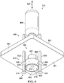
- FIG. 6 an illustration of a bottom isometric view of sealant applicator 212 seen in the direction of lines 6-6 in Figure 5 is depicted in accordance with an illustrative embodiment.
- shaping portion 400 , centering portion 402 , and number of support elements 410 are shown extending from lower surface 601 of base portion 503 .
- shaping portion 400 may include cavity 600 .
- Cavity 600 may be one example of an implementation for cavity 138 in Figure 1 .
- Cavity 600 may be configured to receive fastener 304 .
- shaping portion 400 may have inner surface 602 .
- Inner surface 602 may be configured such that sealant 124 may not adhere to inner surface 602 .
- inner surface 602 may include a coating such as liner 152 in Figure 1 .
- number of support elements 410 may comprise a number of attachment portions 604 .
- Attachment portions 604 may be examples of implementations for attachment portions 172 in Figure 1 .
- Attachment portions 604 may include attachment portion 606 , attachment portion 608 , attachment portion 610 , and attachment portion 612 .
- Attachment portion 606 , attachment portion 608 , attachment portion 610 , and attachment portion 612 may correspond to support element 512 , support element 514 , support element 516 , and support element 518 , respectively.
- attachment portions 604 may be suction cups configured to attach to surface 420 of stringer 202 .
- attachment portions 604 may attach to surface 420 of stringer 202 in some other manner, depending on the type of surface 420 of stringer 202 .
- attachment portions 604 may be magnets. In this case, a counter magnet external to surface 420 of stringer 202 may be used. When stringer 202 is a composite structure, attachment portions 604 may be configured to attach to stringer 202 in some other manner.
- centering portion 402 may comprise channel 614 and interlocking base section 616 .
- Channel 614 and interlocking base section 616 may be examples of implementations for channel 154 and interlocking base section 166 shown in block form in Figure 1 .
- Channel 614 may be configured to deliver sealant 124 to cavity 600 when shaping portion 400 may be arranged over fastener 304 .
- channel 614 may also have a coating (not shown) such that sealant 124 may not adhere to channel 614 . When the coating is present, the coating may be an example of liner 152 in Figure 1 .
- the material properties of plastic may not allow sealant 124 to adhere to channel 614 .
- Interlocking base section 616 of centering portion 402 may be configured to engage inner surface 602 of shaping portion 400 such that fluid 122 in Figure 1 may not pass through the interface of centering portion 402 and shaping portion 400 .
- interlocking base section 616 may substantially prevent sealant 124 in cavity 600 from leaking out of shaping portion 400 , centering portion 402 , or both.
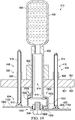
- FIG 7 an illustration of an exploded view of sealant applicator 212 in Figure 6 is depicted in accordance with an illustrative embodiment. In this depicted example, an exploded view of sealant applicator 212 is shown.
- sealant cartridge 406 may include cavity 700 .
- cavity 700 may hold sealant 124 in sealant cartridge 406 .
- sealant cartridge 406 may be configured to be removable such that other types of cartridges or attachments may be used in sealant applicator 212 .
- sealant cartridge 406 may be removed and replaced by a cartridge that may hold a different type of fluid, depending on the particular implementation.
- top portion 702 of centering portion 402 may engage with cavity 700 of sealant cartridge 406 .
- Centering portion 402 may be configured to fit through opening 704 in base portion 503 of sealant applicator 212 such that centering portion 402 may move along axis 505.
- Shaping portion 400 may be sleeved around centering portion 402 in the illustrative example.
- shaping portion 400 may be configured such that shaping portion 400 may not pass through opening 704 in base portion 503. In other illustrative examples, shaping portion 400 may pass through opening 704 as centering portion 402 extends and retracts along axis 505.
- Support element 512 , support element 514 , support element 516 , and support element 518 may extend and retract along axis 505 through opening 706 , opening 708 , opening 710 , and opening 712 , respectively.
- Attachment portion 606 , attachment portion 608 , attachment portion 610 , and attachment portion 612 may not be configured to retract through opening 706 , opening 708 , opening 710 , and opening 712 , respectively, in some examples. In other examples, attachment portion 606 , attachment portion 608 , attachment portion 610 , and attachment portion 612 may fully retract into housing 302.
- centering portion 402 is shown as having a cylindrical shape in the illustrative example, centering portion 402 may have a number of different shapes in other illustrative examples.
- centering portion 402 may have a rectangular shape, a triangular shape, a hexagonal shape, an octagonal shape, or some other suitable shape that may fit through opening 704 and engage with cavity 700 of sealant cartridge 406 .
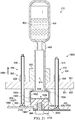
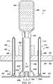
- sealant applicator 212 arranged over fastener 304 seen along lines 8-8 in Figure 4 is depicted in accordance with an illustrative embodiment.
- sealant applicator 212 is shown in retracted position 800.
- centering portion 402 and number of support elements 410 may be seen retracted into housing 302.
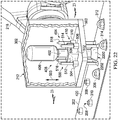
- Figures 9-14 are illustrations of cross-sectional views of sealant applicator 212 taken along lines 9-9 in Figure 5 .
- Figures 9-14 may describe one method for applying layer of sealant 114 over fastener 304.
- centering portion 402 and shaping portion 400 in sealant applicator 212 may be aligned over fastener 304 by robotic device 216 or human operator 220 , as described above.
- sealant applicator 212 may begin in retracted position 800.
- sealant cartridge 406 may include sealant 900 and hold sealant 900 until sealant applicator 212 delivers sealant 900 to cavity 600 to cover and seal fastener 304.
- Centering portion 402 and shaping portion 400 may be configured to move in the direction of arrow 902.
- FIG 10 an illustration of sealant applicator 212 in an extended position is depicted in accordance with an illustrative embodiment.
- Centering portion 402 may have been moved in the direction of arrow 902 in Figure 9 to extended position 1000.
- interlocking base section 616 of centering portion 402 may be substantially flush with surface 420 of stringer 202.
- shaping portion 400 which may be moveably connected to centering portion 402 , may move as well. In this instance, gravity may cause shaping portion 400 to slide downward toward surface 420 of stringer 202.
- an additional movement system may be present to move shaping portion 400.
- centering portion 402 may be configured for a specific type or size of fastener.
- centering portion 402 may be configured to receive a particular size of fastener 304.
- centering portion 402 may be resized to fit multiple sizes of fastener 304 .
- centering portion 402 may be detached from sealant applicator 212 and changed with another centering portion having a different size.
- centering portion 402 may be configured to center fastener 304 in cavity 600 of shaping portion 400 .
- Inner surface 1002 of channel 614 of centering portion 402 may be substantially flush with fastener 304 .
- none of sealant 900 may flow through channel 614 .
- centering portion 402 may be configured to place shaping portion 400 in desired position 1004 about fastener 304.
- Desired position 1004 may be an example of one implementation for desired position 158 in Figure 1 .
- desired position 1004 may be selected such that sealant 900 may be applied to fastener 304 in a desired manner.
- support system 404 with number of support elements 410 may not move as centering portion 402 moves.
- Support system 404 may be configured to move in the direction of arrow 1006 , as shown in Figure 11 .
- FIG. 11 an illustration of support system 404 of sealant applicator 212 in an extended position is depicted in accordance with an illustrative embodiment.
- Number of actuators 500 may have moved support system 404 toward surface 420 of stringer 202 in the direction of arrow 1006 in Figure 10 .
- Attachment portions 604 may then attach to surface 420 of stringer 202 such that sealant applicator 212 may not move in an undesired manner during application of sealant 900 to fastener 304.
- centering portion 402 may then be configured to move upward, in the direction of arrow 1100 , as shown in Figure 12 .
- FIG 12 an illustration of centering portion 402 of sealant applicator 212 in a partially retracted position is depicted in accordance with an illustrative embodiment.
- Centering portion 402 may have been moved by actuator 502 in the direction of arrow 1100 in Figure 11 to partially retracted position 1200.
- partially retracted position 1200 may be a position where interlocking base section 616 of centering portion 402 may engage with inner surface 602 of shaping portion 400 , as described above.
- Partially retracted position 1200 also may be a position where interlocking base section 616 of centering portion 402 may engage with inner surface 602 of shaping portion 400 without moving shaping portion 400 away from surface 420 of stringer 202.
- shaping portion 400 may remain substantially flush with surface 420 when centering portion 402 is in partially retracted position 1200 such that sealant 900 may not flow out of cavity 600 in shaping portion 400.
- Sealant 900 may be dispensed over fastener 304 at a desired time.
- human operator 178 in Figure 1 may determine when sealant 900 may be dispensed and use handheld device 139 to allow sealant 900 to flow into centering portion 402.
- the fluid dynamics of sealant 900 may allow desired flow of sealant 900 when centering portion 402 is in partially retracted position 1200.
- a feedback system may be employed.
- This feedback system may be implemented as, for example, without limitation, controller 137 , which would then allow a valve or some other dispensing tool to dispense sealant 900.
- sealant 900 may be delivered to cavity 600 in shaping portion 400 through channel 614 in centering portion 402 to form layer of sealant 1300.
- sealant 900 may flow in the direction of arrow 1302 through channel 614 in centering portion 402.
- layer of sealant 1300 may be one example of an implementation for layer of sealant 114 in Figure 1 .
- centering portion 402 and shaping portion 400 may be retracted. For instance, centering portion 402 and shaping portion 400 may move in the direction of arrow 1304.
- FIG 14 an illustration of sealant applicator 212 forming layer of sealant 1300 over fastener 304 is depicted in accordance with an illustrative embodiment.
- Centering portion 402 may have been moved in the direction of arrow 1304 in Figure 13 back to retracted position 800.
- shaping portion 400 may move upward with centering portion 402 when centering portion 402 may be retracted.
- support system 404 with number of support elements 410 may remain in extended position 1000 (as seen in Figure 10 and Figure 11 ) as centering portion 402 may be retracted.
- centering portion 402 and shaping portion 400 may not retract from fastener 304 with layer of sealant 1300 unevenly.
- seal cap 1400 formed with layer of sealant 1300 may have desired thickness 1402 over fastener 304.
- Desired thickness 1402 may be one example of an implementation for desired thickness 142 in Figure 1 .
- Desired thickness 1402 may be uniform thickness 144 in Figure 1 .
- layer of sealant 1300 may be applied to fastener 304 in a desired manner to have desired thickness 1402. Because support system 404 may remain in place during removal of layer of sealant 1300 and fastener 304 from cavity 600 of shaping portion 400 , removal of layer of sealant 1300 and fastener 304 from cavity 600 of shaping portion 400 may occur without substantially altering the shape, thickness, or size of layer of sealant 1300. As a result, seal cap 1400 for fastener 304 may be formed more quickly and efficiently and with less rework than with some currently used sealant applicators.
- sealant applicator 212 may be placed over object 1500.
- Object 1500 may have uneven surface 1502.
- shaping portion 400 of sealant applicator 212 may be replaced with shaping portion 1504.
- Shaping portion 1504 may have number of interlocking sections 1506.
- Shaping portion 1504 and number of interlocking sections 1506 may be one example of an implementation for shaping portion 130 with number of interlocking sections 146 shown in block form in Figure 1 .
- shaping portion 1504 with number of interlocking sections 1506 may have cavity 1508, which may be another example of an implementation for cavity 138 in Figure 1 .
- Number of interlocking sections 1506 may allow sealant applicator 212 to apply sealant 900 (not shown) to fastener 304 in a desired manner when fastener 304 may be located on uneven surface 1502.
- Figures 16-21 are illustrations of cross-sectional views of sealant applicator 212 with number of interlocking sections 1506 taken along lines 16-16 in Figure 15 .
- Figures 16-21 may describe one method for applying layer of sealant 1300 over fastener 304.
- centering portion 402 and shaping portion 1504 in may be aligned over fastener 304 by robotic device 216 or human operator 220 , as described above.
- sealant applicator 212 may begin in retracted position 1600, as described above.
- inner surface 1602 of shaping portion 1504 may be shown.
- Inner surface 1602 may have liner 1604.
- Liner 1604 may be another implementation for liner 152 in Figure 1 .
- Liner 1604 may line cavity 1508 of shaping portion 1504 such that sealant 900 may not pass between each of number of interlocking sections 1506 and centering portion 402. In other words, liner 1604 may substantially prevent leakage of sealant 900.
- liner 1604 may be configured to cover substantially all of inner surface 1602 of shaping portion 1504. In this illustrative example, liner 1604 may partially cover inner surface 1602 of shaping portion 1504.
- centering portion 402 and shaping portion 1504 may be configured to move toward uneven surface 1502 of object 1500. Centering portion 402 and shaping portion 1504 may move in the direction of arrow 1606.
- FIG 17 an illustration of centering portion 402 in an extended position is depicted in accordance with an illustrative embodiment.
- Centering portion 402 may have been moved in the direction of arrow 1606 in Figure 16 to extended position 1700.
- interlocking base section 616 may be substantially flush with uneven surface 1502 of object 1500 on one side of fastener 304.
- some of number of interlocking sections 1506 may fall to first height 1702 of uneven surface 1502
- others of number of interlocking sections 1506 may fall to second height 1704 of uneven surface 1502.
- some of number of interlocking sections 1506 may be at different heights, depending on the contour of uneven surface 1502.
- number of interlocking sections 1506 may provide sealant applicator 212 with the ability to seal fastener 304 on uneven surface 1502 in a desired manner.
- liner 1604 on inner surface 1602 of shaping portion 1504 may move to rest on first height 1702 of uneven surface 1502.
- liner 1604 may completely cover inner surface 1602 such that sealant 900 may not reach number of interlocking sections 1506.
- liner 1604 also may be sectioned.
- sealant 900 may flow into cavity 1508 such that leakage of sealant 900 may be reduced. The reduction may result in an absence of a leakage of sealant 900.
- centering portion 402 may be configured to center fastener 304 in cavity 1508 of shaping portion 1504. In these depicted examples, centering portion 402 may be configured to place shaping portion 1504 in desired position 1706 about fastener 304 . Desired position 1706 may be another example of one implementation for desired position 158 in Figure 1 . In particular, desired position 1706 may be selected such that sealant 900 may be applied to fastener 304 in a desired manner.
- support system 404 with number of support elements 410 may not move as centering portion 402 moves.
- Support system 404 may be configured to move in the direction of arrow 1708 , as shown in Figure 18 .
- FIG. 18 an illustration of support system 404 in an extended position is depicted in accordance with an illustrative embodiment.
- Number of actuators 500 may have moved support system 404 toward surface 420 of object 1500 in the direction of arrow 1708 in Figure 10 .
- Number of support elements 410 with attachment portions 604 may then attach to uneven surface 1502 of object 1500 such that sealant applicator 212 may not move in an undesired manner during application of sealant 900 to fastener 304 .
- support element 516 with attachment portion 610 may be configured to attach to first height 1702 of uneven surface 1502, while support element 518 with attachment portion 612 , support element 512 with attachment portion 606 , and support element 514 with attachment portion 608 may be configured to attach to second height 1704 of uneven surface 1502.
- number of support elements 410 may move independently of each other.
- centering portion 402 may then be configured to move upward, in the direction of arrow 1800 , as shown in Figure 19 .
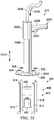
- FIG 19 an illustration of centering portion 402 in a partially retracted position is depicted in accordance with an illustrative embodiment.
- Centering portion 402 may have been moved by actuator 502 in the direction of arrow 1800 in Figure 18 to partially retracted position 1900.
- partially retracted position 1900 may be a position where interlocking base section 616 of centering portion 402 may engage with liner 1604 of inner surface 1602 of shaping portion 1504.
- Partially retracted position 1900 also may be a position where interlocking base section 616 of centering portion 402 may engage with liner 1604 of inner surface 602 of shaping portion 1504 without moving number of interlocking sections 1506 away from uneven surface 420 of object 1500.
- number of interlocking sections 1506 may remain substantially flush with first height 1702 and second height 1704 of uneven surface 1502 when centering portion 402 may be in partially retracted position 1900 such that sealant 900 may not flow out of cavity 1508 in shaping portion 1504.
- sealant 900 may be delivered to cavity 1508 in shaping portion 1504 through channel 614 in centering portion 402 to form layer of sealant 2000.
- sealant 900 may flow in the direction of arrow 2002 through channel 614 in centering portion 402.
- layer of sealant 2000 may be one example of an implementation for layer of sealant 114 in Figure 1 .
- centering portion 402 and shaping portion 1504 with number of interlocking sections 1506 may be retracted. For instance, centering portion 402 and shaping portion 1504 may move in the direction of arrow 2004.
- FIG 21 an illustration of sealant applicator 212 forming layer of sealant 1300 over fastener 304 is depicted in accordance with an illustrative embodiment.
- Centering portion 402 may have been moved in the direction of arrow 2004 in Figure 20 back to retracted position 1600.
- shaping portion 1504 with number of interlocking sections 1506 may move upward with centering portion 402 when centering portion 402 may be retracted.
- seal cap 2100 may be formed with desired thickness 2102 over fastener 304. Desired thickness 2102 may be one example of an implementation for desired thickness 142 in Figure 1 . Desired thickness 2102 may be uniform thickness 144 in Figure 1 . In this example, desired thickness 2102 may be a desired thickness on both first height 1702 and second height 1704 of uneven surface 1502 such that seal cap 2100 covers and seals fastener 304 in a desired manner.
- sealant applicator 212 layer of sealant 2000 may be applied to fastener 304 in a desired manner to have desired thickness 2102. Because support system 404 may remain in place during removal of layer of sealant 2000 and fastener 304 from cavity 1508 of shaping portion 1504, removal of layer of sealant 2000 and fastener 304 from cavity 1508 of shaping portion 1504 may occur without substantially altering the shape, thickness, or size of layer of sealant 2000. As a result, seal cap 2100 for fastener 304 may be formed more quickly and efficiently and with less rework than with some currently used sealant applicators. Moreover, with the use of number of interlocking sections 1506, seal cap 2100 may be formed on uneven surface 1502 in a desired manner.
- sealant applicator 212 may be arranged over stringer 202 , as described above.
- shaping portion 400 of sealant applicator 212 may be replaced with shaping portion 2200.
- Shaping portion 2200 may have dome shape 2202 in this illustrative example.
- shaping portion 2200 may have number of interlocking sections 1506 as seen in Figures 15-20 .
- FIG 23 an illustration of a cross-sectional view of shaping portion 2200 taken along lines 23-23 from Figure 22 is depicted in accordance with an illustrative embodiment.
- Cavity 2300 of shaping portion 2200 is shown.
- the shape of cavity 2300 may be substantially dome shape 2202.
- interlocking base section 2302 of centering portion 402 may have a different shape than interlocking base section 616 shown in Figures 6-14 .
- interlocking base section 2302 may have a shape that may conform to dome shape 2202 of inner surface 2304 of shaping portion 2200 such that sealant may not leak out of shaping portion 2200.
- sealant applicator 214 is depicted in accordance with an illustrative embodiment.
- sealant applicator 214 is shown with respect to view lines 24-24 in Figure 2 .
- Sealant applicator 214 may be operated manually by human operator 220 from Figure 2 to apply sealant 124 to number of fasteners 210 in this example.
- housing 302 in Figure 3 has been replaced with housing 2400.
- Housing 2400 includes base portion 2402 and handheld device 2404.
- Handheld device 2404 may be one example of an implementation for handheld device 139 shown in block form in Figure 1 .
- handheld device 2404 may include grip 2405 and trigger 2407.
- Grip 2405 may be configured such that human operator 220 may hold grip 2405 in a desired manner.
- Trigger 2407 may be a device that dispenses sealant 124.
- trigger 2407 may be one example of controller 137 shown in Figure 1 .
- trigger 2407 may be a button. In other illustrative examples, trigger 2407 may be a different type of device, depending on the particular implementation.
- sealant applicator 214 may be configured to be a pneumatic device with air line 2406 physically attached to housing 2400. Automated pneumatic pressure from air line 2406 may apply a force to a plunger (not shown) in the direction of arrow 2409 to extrude sealant 124 from sealant cartridge 2408 when sealant cartridge 2408 is placed in housing 2400. Sealant cartridge 2408 may be one example of an implementation for sealant cartridge 176 in Figure 1 .
- sealant applicator 214 may be configured to apply a desired level of pneumatic pressure to sealant 124 in sealant cartridge 2408.
- the pneumatic pressure may be adjusted based on the properties of the type of sealant 124 used by sealant applicator 214. This adjustment may be done automatically or manually.
- sealant applicator 214 comprises similar elements to sealant applicator 212 .
- sealant applicator 214 includes shaping portion 400 , centering portion 402 (not shown), movement system 408 , and number of support elements 410 .
- human operator 220 may position centering portion 402 over one of number of fasteners 210 on surface 2410 of stringer 204 . Human operator 220 may then position shaping portion 400 such that shaping portion 400 is flush with surface 2410 of stringer 204. Movement system 408 , human operator 220 , or a combination of the two may position number of support elements 410 on surface 2410 of stringer 204 such that number of support elements 410 attach to surface 2410.
- Human operator 220 may then manually pull centering portion 402 away from surface 2410 until centering portion 402 is in a partially retracted position.
- human operator 220 may push trigger 2407 to dispense sealant 124 from sealant cartridge 2408 using automated pneumatic force exerted on the plunger of sealant cartridge 2408 to extrude sealant 124.
- human operator 220 may pull sealant applicator 214 away from surface 2410 such that number of support elements 410 detach from surface 2410.
- sealant applicator 214 may be used to form seal cap 2426 , seal cap 2428 , and seal cap 2430 in this illustrative example.
- sealant applicator 214 an illustration of an exploded view of sealant applicator 214 from Figure 24 is depicted in accordance with an illustrative embodiment.
- a more detailed illustration of the components in sealant applicator 214 may be seen. These components may be similar to the components shown with respect to sealant applicator 212 shown in Figure 6 . These components operate as described above.
- sealant applicator 214 is shown in Figure 24 and 25 as having housing 2400 with grip 2405 and trigger 2407 , this depiction is not meant to limit the manner in which a handheld sealant applicator may be configured. Other types of handheld devices may be used, housing 2400 may be absent from sealant applicator 214 , sealant applicator 214 may include a different sealant source other than sealant cartridge 2408, or other desirable modifications may apply, depending on the functionality involved.
- FIG. 26 an illustration of a robotic device with an array of sealant applicators is depicted in accordance with an illustrative embodiment.
- Robotic device 216 with arm 218 from Figure 2 is shown with a sealant applicator array arranged over an object.
- sealant applicator 212 may be replaced with sealant applicator array 2600 and arranged over number of fasteners 2604 along object 2602.
- Sealant applicator array 2600 may comprise sealant applicator 2608, sealant applicator 2610, and sealant applicator 2612, which may be examples of implementations for sealant applicator 128 in Figure 1 .
- Number of fasteners 2604 and object 2602 with surface 2606 may be an example of one implementation for number of fasteners 110 and object 102 with surface 150 in Figure 1 , respectively.
- Rail system 2614 may attach sealant applicator 2608, sealant applicator 2610, and sealant applicator 2612 with each other.
- Rail system 2614 may be only one example of a system for attaching sealant applicator 2608, sealant applicator 2610, and sealant applicator 2612 with each other.
- Tracks or other suitable types of movement devices also may be used in other illustrative examples.
- sealant applicator 2608, sealant applicator 2610, and sealant applicator 2612 may move relative to one another along rail system 2614 in the direction of arrow 2615 to adjust for different sizes and distances between number of fasteners 2604. Sealant applicator 2608, sealant applicator 2610, and sealant applicator 2612 may operate similar to sealant applicator 212 , as described herein.
- sealant applicator array 2600 may increase the efficiency and reduce the rework of the sealant application process.
- Figures 2-26 may be illustrative examples of how components shown in block form in Figure 1 can be implemented as physical structures. Additionally, some of the components in Figures 2-26 may be combined with components in Figure 1 , used with components in Figure 1 , or a combination of the two.
- FIG. 27 an illustration of a flowchart of a process for applying sealant to a fastener system is depicted in accordance with an illustrative embodiment.
- the process illustrated in Figure 27 may be implemented by sealant applicator 128 to form, for example, without limitation, layer of sealant 114 over fastener 116 on surface 150 of object 102 in Figure 1 .
- the process may begin by aligning sealant applicator 128 over fastener system 108 (operation 2700 ). Next, centering portion 132 and shaping portion 130 may be extended toward surface 150 of object 102 (operation 2702 ).
- the process may receive fastener system 108 in cavity 138 of shaping portion 130 of sealant applicator 128 (operation 2704 ).
- Fastener system 108 may then be received in channel 154 of centering portion 132 such that shaping portion 130 may be positioned in desired position 158 around fastener system 108 (operation 2706 ).
- centering portion 132 may move along axis 164 to extended position 160 to receive fastener 116 in fastener system 108.
- support system 134 may be extended toward surface 150 of object 102 (operation 2708 ). Support system 134 may then be secured to surface 150 of object 102 (operation 2710 ). In this illustrative example, each of number of support elements 170 may be attached to surface 150 of object 102 .
- shaping portion 130 comprises number of interlocking sections 146 , some of number of interlocking sections 146 may attach to different heights of surface 150 , depending on the particular implementation.
- Centering portion 132 may be retracted along axis 164 to retracted position 162 (operation 2712 ).
- Shaping portion 130 may be held in desired position 158 using support system 134 (operation 2714 ).
- shaping portion 130 may be held in desired position 158 by support system 404 while centering portion 132 may be retracted by actuator 502 to partially retracted position 1200 .
- interlocking base section 166 of centering portion 132 may be engaged with inner surface 168 of shaping portion 130 (operation 2716 ).
- Sealant 124 may be delivered into cavity 138 of shaping portion 130 to form layer of sealant 114 over fastener system 108 (operation 2718 ).
- sealant applicator 128 is removed from fastener system 108 (operation 2720 ) and the process terminates.
- each block in the flowcharts or block diagrams may represent a module, a segment, a function, and/or a portion of an operation or step.
- the function or functions noted in the blocks may occur out of the order noted in the figures.
- two blocks shown in succession may be executed substantially concurrently, or the blocks may sometimes be performed in the reverse order, depending upon the functionality involved.
- other blocks may be added in addition to the illustrated blocks in a flowchart or block diagram.
- aircraft manufacturing and service method 2800 may be described in the context of aircraft manufacturing and service method 2800 as shown in Figure 28 and aircraft 2900 as shown in Figure 29 .
- Figure 28 an illustration of an aircraft manufacturing and service method is depicted in accordance with an illustrative embodiment.
- aircraft manufacturing and service method 2800 may include specification and design 2802 of aircraft 2900 in Figure 29 and material procurement 2804.
- aircraft 2900 in Figure 29 may go through certification and delivery 2810 in order to be placed in service 2812. While in service 2812 by a customer, aircraft 2900 in Figure 29 is scheduled for routine maintenance and service 2814 , which may include modification, reconfiguration, refurbishment, and other maintenance or service.
- Each of the processes of aircraft manufacturing and service method 2800 may be performed or carried out by a system integrator, a third party, and/or an operator.
- the operator may be a customer.
- a system integrator may include, without limitation, any number of aircraft manufacturers and major-system subcontractors
- a third party may include, without limitation, any number of vendors, subcontractors, and suppliers
- an operator may be an airline, a leasing company, a military entity, a service organization, and so on.
- aircraft 2900 is produced by aircraft manufacturing and service method 2800 in Figure 28 and may include airframe 2902 with plurality of systems 2904 and interior 2906.
- systems 2904 include one or more of propulsion system 2908 , electrical system 2910 , hydraulic system 2912 , and environmental system 2914 . Any number of other systems may be included.
- propulsion system 2908 includes one or more of propulsion system 2908 , electrical system 2910 , hydraulic system 2912 , and environmental system 2914 . Any number of other systems may be included.
- an aerospace example is shown, different illustrative embodiments may be applied to other industries, such as the automotive industry.
- Apparatuses and methods embodied herein may be employed during at least one of the stages of aircraft manufacturing and service method 2800 in Figure 28 .
- layer of sealant 114 from Figure 1 may be applied during any one of the stages of aircraft manufacturing and service method 2800.
- sealant applicator 128 from Figure 1 may be used to apply layer of sealant 114 to fastener 116 during at least one of component and subassembly manufacturing 2806, system integration 2808, routine maintenance and service 2814 , or some other stage of aircraft manufacturing and service method 2800.
- components or subassemblies produced in component and subassembly manufacturing 2806 in Figure 28 may be fabricated or manufactured in a manner similar to components or subassemblies produced while aircraft 2900 is in service 2812 in Figure 28 .
- one or more apparatus embodiments, method embodiments, or a combination thereof may be utilized during production stages, such as component and subassembly manufacturing 2806 and system integration 2808 in Figure 28 .
- One or more apparatus embodiments, method embodiments, or a combination thereof may be utilized while aircraft 2900 is in service 2812 and/or during maintenance and service 2814 in Figure 28 .
- the use of a number of the different illustrative embodiments may substantially expedite the assembly of and/or reduce the cost of aircraft 2900.
- sealant applicator 128 may comprise shaping portion 130 , centering portion 132 , and support system 134.
- Shaping portion 130 may have cavity 138 and may be configured to receive fastener system 108.
- Shaping portion 130 may be further configured to receive sealant 124 within cavity 138 to form layer of sealant 114 over fastener system 108 within cavity 138.
- Centering portion 132 may be moveably located within cavity 138 of shaping portion 130 and may have channel 154. Centering portion 132 may be configured to position shaping portion 130 in desired position 158 around fastener system 108 when fastener system 108 is received in cavity 138.
- Centering portion 132 may be further configured to deliver sealant 124 into cavity 138 of shaping portion 130.
- Support system 134 may be physically associated with shaping portion 130.
- Support system 134 may be configured to hold shaping portion 130 in desired position 158 when sealant 124 flows into cavity 138 to form layer of sealant 114.
- layer of sealant 114 may be applied with desired thickness 142. Desired thickness 142 may stay substantially the same during all phases of application with the use of an illustrative embodiment. In this manner, embodiments of the present disclosure may provide efficient and cost effective sealant application. Additionally, fewer of number of fasteners 110 in fastener system 108 may have to be reworked.
Description
- The present disclosure relates generally to applying a coating to objects and, in particular, to applying sealant to objects. Still more particularly, the present disclosure relates to a method and apparatus for applying sealant to a fastener system with a self-centering sealant applicator.
- With manufacturing objects, a layer of sealant may be applied to each object to protect the object from various environmental effects. The layer of sealant may be used to cover and seal fasteners in a fastener system such as, for example, without limitation, screws and bolts. In some cases, sealant may be applied to a fastener to lower the risk of corrosion or electromagnetic effects.
- Typically, a layer of sealant may cover a fastener by placing the sealant within a cap and then placing the cap over the head of the fastener. This cap may be associated with a sealant cartridge to form a sealant applicator. In some cases, the sealant applicator may be referred to as a dauber. The sealant applicator may be conducted by a human operator in some situations.
- During installation, the cap and the sealant may be pressed down over the fastener to ensure that the sealant adheres to and covers the fastener to form a layer. The cap may then be removed from the fastener. However, often times, sealant may be applied unevenly around the fastener. In other cases, excess sealant may squeeze out from under the cap when the cap and the sealant are placed over the fastener and pressed downward.
- An uneven or excess application of the sealant may be undesirable. For example, without limitation, unevenly applied or excess sealant may not meet manufacturing safety or quality standards provided by manufacturers, the government, or other organizations. As an example, a specified thickness for the layer of sealant may be desired over the fastener to meet safety standards for the object.
- With some currently available methods for applying sealant, the thickness of the sealant over the fastener may be uneven, resulting in a fastener that does not meet manufacturing standards. Fasteners that do not meet these standards may need to be discarded or reworked. This process may be more time-consuming or expensive than desired.
- When an object comprises multiple fasteners over which a layer of sealant is to be formed, the time needed to measure and rework fasteners may increase production times for the object, cost of the object, or both more than desired. Accordingly, there is a need for a method and apparatus which take into account one or more of the issues discussed above as well as possibly other issues.
-
US2011/024943 , in accordance with its abstract, a system and method for dispensing a sealant over aircraft fasteners secured to a surface in the aircraft. The system includes a nozzle tip having a shroud configured for placement over the fasteners. Sealant is metered to the shroud via an orifice within the nozzle tip. The shroud is sized to leave a space between it and the fastener to control the amount of sealant applied to the fastener upper surface and along the interface between the fastener and aircraft surface. Pressurized fluid urges the sealant through the orifice.. -
WO2013/154773 , in accordance with its abstract, a cap (10) for sealing a mechanical fastener (200), method for making the cap, and driver and method for applying the cap is disclosed. The cap includes a shell having an exterior surface (14) and an interior surface (16) defining a cavity (18), an opening (19) extending through the shell between the interior and exterior surfaces, and a sealant (13) at least partially filling the cavity. A package and a holder for holding a plurality of cap assemblies are also disclosed. - In one illustrative example, an apparatus may comprise a shaping portion, a centering portion, and a support system. The shaping portion may have a cavity configured to receive a fastener system and receive a sealant. The centering portion may have a channel configured to position the shaping portion in a desired position around the fastener system when the fastener system is received in the cavity. The support system may be configured to maintain a desired position of the apparatus.
- In another illustrative example, a method for applying sealant may be provided. A fastener system may be received in a channel of a centering portion of a sealant applicator such that a shaping portion of the sealant applicator may be positioned in a desired position around the fastener system. The shaping portion may be held in the desired position. A layer of sealant may be formed over the fastener system.
- In yet another illustrative example, an apparatus may comprise a shaping portion having a cavity and a number of interlocking sections having uniform dimensions, a centering portion, and a support system. The shaping portion may be configured to move independently of other interlocking sections. The shaping portion may be further configured to receive a fastener system within the cavity. The shaping portion may be further configured to receive a sealant within the cavity to form a layer of sealant over the fastener system having a uniform thickness. The centering portion may be moveably located within the cavity of the shaping portion. The centering portion may have a channel and an interlocking base section. The centering portion may be configured to position the shaping portion in a desired position around the fastener system when the fastener system is received in the cavity. The centering portion may be further configured to move between an extended position and a retracted position such that the shaping portion may be in the desired position around the fastener system when the centering portion is in the extended position. The centering portion may move along an axis extending centrally through the fastener system when moving between the extended position and the retracted position. The centering portion may be still further configured to receive the fastener system in the channel when in the extended position and move the fastener system out of the channel when in the retracted position. The interlocking base section may be configured to engage with an inner surface in the cavity of the shaping portion when the centering portion is in the retracted position. The centering portion may be further configured to deliver the sealant into the cavity of the shaping portion when the cavity portion is in the retracted position. The support system may be physically associated with the shaping portion and the centering portion, selected from at least one of a vacuum sealing device, a magnet clamping system, a lock, a clip, a track, a mechanical relative position location device, or a robotic arm. The support system may comprise a number of support elements configured to secure the number of support elements to a surface of an object in which the fastener system is installed. The support system may be configured to hold the apparatus in the desired position when the centering portion and the shaping portion retract to form the layer of sealant over the fastener. The support system may be further configured to maintain the desired position of the centering portion as the centering portion moves between the extended position and the retracted position. The support system may be still further configured to maintain the desired position of the shaping portion as the shaping portion is removed from the fastener system. The shaping portion, the centering portion, and the support system may form one of a sealant applicator or an automatic sealant applicator.
- In still another illustrative example, a method for applying sealant may be provided. A fastener system may be received in a cavity of a shaping portion of a sealant applicator. A centering portion of the sealant applicator may be extended along an axis extending centrally through the fastener system. The centering portion may be configured to move between an extended position and a retracted position. The fastener system may be received in a channel of the centering portion when the centering portion is in the extended position such that the shaping portion is positioned in a desired position around the fastener system. The shaping portion may be held in the desired position using a support system such that a number of support elements of the shaping portion may maintain a desired position of the apparatus relative to a surface. The centering portion may be retracted along the axis such that an interlocking base section of the centering portion engages with an inner surface of the shaping portion. A sealant may be delivered into the cavity of the shaping portion of the sealant applicator to form a layer of sealant over the fastener system. The layer of sealant may have a uniform thickness.
In summary, according to one aspect there is provided an apparatus comprising: - a shaping portion having a cavity configured to receive a fastener system and receive a sealant;
- a centering portion having a channel configured to position the shaping portion in a desired position around the fastener system when the fastener system is received in the cavity; and
- a support system configured to maintain the desired position of the apparatus, wherein the centering portion is configured to:
- move between an extended position and a retracted position;
- position the shaping portion in the desired position around the fastener system when the centering portion is in the extended position; and
- deliver the sealant into the cavity when the centering portion is moved into the retracted position.
- Advantageously the apparatus wherein the sealant received in the cavity of the shaping portion forms a layer of sealant over the fastener system within the cavity.
- Advantageously the apparatus wherein the support system is physically associated with the shaping portion and the centering portion and is configured to maintain the desired position of the apparatus when the centering portion and the shaping portion retract to form the layer of sealant over the fastener system.
- Advantageously the apparatus wherein the shaping portion, the centering portion, and the support system form at least one of a sealant applicator or an automatic sealant applicator.
- Advantageously the apparatus wherein the centering portion is configured to receive the fastener system in the channel when in the extended position and move the fastener system out of the channel when in the retracted position.
- Advantageously the apparatus wherein the centering portion is configured to move along an axis extending centrally through the fastener system when moving between the extended position and the retracted position.
- Advantageously the apparatus wherein the centering portion includes an interlocking base section configured to engage with an inner surface in the cavity of the shaping portion when the centering portion is in the retracted position.
- Advantageously the apparatus wherein the cavity in the shaping portion is configured to cause the sealant to form a layer of sealant over the fastener system having a uniform thickness.
- Advantageously the apparatus wherein the shaping portion comprises a number of interlocking sections.
- Advantageously the apparatus wherein each of the number of interlocking sections comprises uniform dimensions.
- Advantageously the apparatus wherein the each of the number of interlocking sections is configured to move independently of others of the number of interlocking sections.
- Advantageously the apparatus wherein the support system is configured to maintain the desired position of the centering portion as the centering portion moves between an extended position and a retracted position, and to maintain the desired position of the shaping portion as the shaping portion is removed from the fastener system.
- Advantageously the apparatus wherein the support system is selected from at least one of a vacuum sealing device, a magnet clamping system, a lock, a clip, a track, a mechanical relative position location device, or a robotic arm.
- Advantageously the apparatus wherein the support system comprises a number of attachment portions configured to secure the number of support elements to a surface of an object in which the fastener system is installed.
According to another aspect there is provided a method for applying sealant, the method comprising: - receiving, when a centering portion is in an extended position, a fastener system in a channel of the centering portion of a sealant applicator, such that a shaping portion of the sealant applicator is positioned in a desired position around the fastener system; and
- delivering the sealant into a cavity of the shaping portion when the centering portion is moved into a retracted position while holding the shaping portion in the desired position to thereby form a layer of sealant over the fastener system .
- Advantageously the method wherein a support system holds the shaping portion in the desired position.
- Advantageously the method wherein forming the layer of sealant over the fastener system includes delivering the sealant into the cavity of the shaping portion of the sealant applicator.
- Advantageously the method wherein the layer of sealant has a uniform thickness over the fastener system.
- Advantageously the method further including extending the centering portion along an axis extending centrally through the fastener system to position the shaping portion in the desired position; retracting the centering portion along the axis; and engaging an interlocking base section of the centering portion with an inner surface of the shaping portion.
- Advantageously the method wherein holding the shaping portion in the desired position includes securing a number of support elements.
- According to an example useful for understanding of the invention there is provided an apparatus including a shaping portion having a cavity and a number of interlocking sections having uniform dimensions and configured to move independently of other interlocking sections, in which the shaping portion is configured to: receive a fastener system in the cavity; and receive a sealant within the cavity to form a layer of sealant over the fastener system having a uniform thickness; a centering portion moveably located within the cavity of the shaping portion and having a channel and an interlocking base section, in which the centering portion is configured to: position the shaping portion in a desired position around the fastener system when the fastener system is received in the cavity; move between an extended position and a retracted position such that the shaping portion is in the desired position around the fastener system when the centering portion is in the extended position, in which the centering portion moves along an axis extending centrally through the fastener system when moving between the extended position and the retracted position; receive the fastener system in the channel when in the extended position and move the fastener system out of the channel when in the retracted position, in which the interlocking base section is configured to engage with an inner surface in the cavity of the shaping portion when the centering portion is in the retracted position; and deliver the sealant into the cavity of the shaping portion when the centering portion is in the retracted position; and a support system physically associated with the shaping portion and the centering portion selected from at least one of a vacuum sealing device, a magnet clamping system, a lock, a clip, a track, a mechanical relative position location device, or a robotic arm, the support system comprising a number of support elements configured to secure the number of support elements to a surface of an object in which the fastener system is installed, in which the support system is configured to: hold the apparatus in the desired position when the centering portion and the shaping portion retract to form the layer of sealant over the fastener; maintain the desired position of the centering portion as the centering portion moves between the extended position and the retracted position; and maintain the desired position of the shaping portion as the shaping portion is removed from the fastener system, in which the shaping portion, the centering portion, and the support system form one of a sealant applicator or an automatic sealant applicator.
- According to another example useful for understanding of the invention there is provided a method for applying sealant, the method including receiving a fastener system in a cavity of a shaping portion of a sealant applicator; extending a centering portion of the sealant applicator along an axis extending centrally through the fastener system, in which the centering portion is configured to move between an extended position and a retracted position; receiving the fastener system in a channel of the centering portion when the centering portion is in the extended position such that the shaping portion is positioned in a desired position around the fastener system; holding the shaping portion in the desired position using a support system such that a number of support elements of the shaping portion maintain a desired position of an apparatus relative to a surface; retracting the centering portion along the axis such that an interlocking base section of the centering portion engages with an inner surface of the shaping portion; and delivering the sealant into the cavity of the shaping portion of the sealant applicator to form a layer of sealant over the fastener system, in which the layer of sealant has a substantially uniform thickness.
- The features and functions can be achieved independently in various embodiments of the present disclosure or may be combined in yet other embodiments in which further details can be seen with reference to the following description and drawings.
- The novel features believed characteristic of the illustrative embodiments are set forth in the appended claims. The illustrative embodiments, however, as well as a preferred mode of use, further objectives and features thereof, will best be understood by reference to the following detailed description of an illustrative embodiment of the present disclosure when read in conjunction with the accompanying drawings, wherein:
-
Figure 1 is an illustration of a block diagram of a manufacturing environment in accordance with an illustrative embodiment; -
Figure 2 is an illustration of a manufacturing environment in accordance with an illustrative embodiment; -
Figure 3 is an illustration of an isometric side view of a sealant applicator in accordance with an illustrative embodiment; -
Figure 4 is an illustration of an isometric side view of a sealant applicator in accordance with an illustrative embodiment; -
Figure 5 is an illustration of a top isometric view of a sealant applicator in accordance with an illustrative embodiment; -
Figure 6 is an illustration of a bottom isometric view of a sealant applicator in accordance with an illustrative embodiment; -
Figure 7 is an illustration of an exploded view of a sealant applicator in accordance with an illustrative embodiment; -
Figure 8 is an illustration of a front view of a sealant applicator arranged over a fastener in accordance with an illustrative embodiment; -
Figure 9 is an illustration of a sealant applicator in accordance with an illustrative embodiment; -
Figure 10 is an illustration of a sealant applicator in an extended position in accordance with an illustrative embodiment; -
Figure 11 is an illustration of a support system of a sealant applicator in an extended position in accordance with an illustrative embodiment; -
Figure 12 is an illustration of a centering portion of a sealant applicator in a partially retracted position in accordance with an illustrative embodiment; -
Figure 13 is an illustration of a sealant applicator applying a sealant to a fastener in accordance with an illustrative embodiment; -
Figure 14 is an illustration of a sealant applicator forming a layer of sealant over a fastener in accordance with an illustrative embodiment; -
Figure 15 is an illustration of a sealant applicator in accordance with an illustrative embodiment; -
Figure 16 is an illustration of a sealant applicator in a retracted position in accordance with an illustrative embodiment; -
Figure 17 is an illustration of a centering portion in an extended position in accordance with an illustrative embodiment; -
Figure 18 is an illustration of a support system in an extended position in accordance with an illustrative embodiment; -
Figure 19 is an illustration of a centering portion in a partially retracted position in accordance with an illustrative embodiment; -
Figure 20 is an illustration of a sealant applicator applying a sealant to a fastener in accordance with an illustrative embodiment; -
Figure 21 is an illustration of a sealant applicator forming a layer of sealant over a fastener in accordance with an illustrative embodiment; -
Figure 22 is an illustration of a sealant applicator in accordance with an illustrative embodiment; -
Figure 23 is an illustration of a cross-sectional view of a shaping portion in accordance with an illustrative embodiment; -
Figure 24 is an illustration of a sealant applicator in accordance with an illustrative embodiment; -
Figure 25 is an illustration of an exploded view of a sealant applicator in accordance with an illustrative embodiment; -
Figure 26 is an illustration of a robotic device with an array of sealant applicators in accordance with an illustrative embodiment; -
Figure 27 is an illustration of a flowchart of a process for applying sealant to a fastener system in accordance with an illustrative embodiment; -
Figure 28 is an illustration of a block diagram of an aircraft manufacturing and service method in accordance with an illustrative embodiment; and -
Figure 29 is an illustration of a block diagram of an aircraft in which an illustrative embodiment may be implemented. - The illustrative embodiments recognize and take into account one or more different considerations. For example, without limitation, the illustrative embodiments recognize and take into account that it may be desirable to have a method and apparatus for applying a layer of sealant to a fastener that reduces the overall time needed to apply sealant to a fastener system. The illustrative embodiments also recognize and take into account that it may be desirable to have a tool that may be configured to apply the layer of sealant over the fastener such that the layer of sealant may be of a specified amount, a specified thickness, or both, on the fastener.
- Additionally, the illustrative embodiments recognize and take into account that when removing the tool from the fastener, it may be desirable to remove the tool from the fastener such that the configuration of the sealant remains substantially in place relative to the fastener. The illustrative embodiments further recognize and take into account that it may be desirable to apply the layer of sealant to the fastener without excess sealant around the base of the fastener.
- Thus, the illustrative embodiments may provide a method and apparatus for applying a sealant to a fastener system. In one illustrative embodiment, a sealant applicator may comprise a shaping portion, a centering portion, and a support system. The shaping portion may have a cavity and may be configured to receive a fastener system. The shaping portion may be further configured to receive a sealant within the cavity to form a layer of sealant over the fastener system within the cavity. The centering portion may be moveably located within the cavity of the shaping portion and may have a channel. The centering portion may be configured to position the shaping portion in a desired position around the fastener system when the fastener system is received in the cavity. The centering portion may be further configured to deliver the sealant into the cavity of the shaping portion. The support system may be physically associated with the shaping portion. The support system may be configured to hold the shaping portion in the desired position when the sealant flows into the cavity to form the layer of sealant.
- Referring now to the figures and, in particular, with reference to
Figure 1 , an illustration of a block diagram of a manufacturing environment is depicted in accordance with an illustrative embodiment.Manufacturing environment 100 may be an example of one environment in which object 102 may be formed. - In the illustrative example, object 102 may take a number of different forms. For example, without limitation, object 102 may be selected from one of a wing box, a spar assembly, a fuselage section, a structural frame, an engine housing, or some other suitable type of object.
- As depicted,
object 102 may be physically associated withplatform 104.Platform 104 may beaircraft 106 in the illustrative example. - When one component is "physically associated" with another component, the association may be a physical association in the depicted examples. For example, without limitation, a first component,
object 102, may be considered to be physically associated with a second component,platform 104, by being secured to the second component, bonded to the second component, mounted to the second component, welded to the second component, fastened to the second component, and/or connected to the second component in some other suitable manner. The first component also may be connected to the second component using a third component. The first component may also be considered to be physically associated with the second component by being formed as part of the second component, an extension of the second component, or both. -
Object 102 may be assembled usingfastener system 108. As depicted,fastener system 108 may include number offasteners 110. As used herein, a "number of' items may include one or more items. In this manner, number offasteners 110 may include one or more fasteners. Number offasteners 110 may include at least one of a screw, a bolt, a pin, a clamp, a tie, a clip, a threaded nut, a crimped or swaged collar, or some other suitable type of fastener. One or more of number offasteners 110 also may be associated with, for example, without limitation, one or more washers, spacers, or other suitable components as part offastener system 108. - As used herein, the phrase "at least one of," when used with a list of items, may mean different combinations of one or more of the listed items may be used and only one of each item in the list may be needed. The item may be a particular object, thing, or category. In other words, "at least one of' may mean any combination of items and number of items may be used from the list, but not all of the items in the list may be required.
- For example, without limitation, "at least one of item A, item B, and item C" may mean item A; item A and item B; item B; item A, item B, and item C; or item B and item C. In some cases, "at least one of item A, item B, and item C" may mean, for example, without limitation, two of item A, one of item B, and ten of item C; four of item B and seven of item C; or some other suitable combination.
- In this illustrative example, number of layers of
sealant 112 may cover, seal, or cover and seal number offasteners 110. In particular, a layer of sealant in number of layers ofsealant 112 may cover corresponding fasteners in number offasteners 110. As one illustrative example, layer ofsealant 114 may cover andseal fastener 116. - Layer of
sealant 114 may protectfastener 116,object 102, or both fromundesired element 120.Undesired element 120 may be one of electricity, heat, fluid, dirt particles, or other types of elements. For example, without limitation, layer ofsealant 114 may reduce the possibility offluid 122 passing through the interface betweenfastener 116 andobject 102. - In other illustrative examples, layer of
sealant 114 may reduce the possibility of other materials such as a fuel, water, or other corrosive elements, liquid or gaseous, from passing through the interface betweenfastener 116 andobject 102. In other words, layer ofsealant 114 may form a barrier. Additionally, layer ofsealant 114 may also be used to reduce or substantially prevent undesired effects resulting from electromagnetic events. - In one illustrative example, layer of
sealant 114 may be formed overfastener 116 by applyingsealant 124 tofastener 116 usingtool 126.Tool 126 may besealant applicator 128 in this illustrative example. - As depicted,
sealant 124 may be comprised of a number of different materials. For example, without limitation,sealant 124 may be comprised of at least one of a silicone material, a rubber material, a polymer, nylon, plastic, or some other suitable type of material. - In this depicted example,
sealant applicator 128 may include shapingportion 130, centeringportion 132, andsupport system 134.Sealant applicator 128 also may includehousing 136.Housing 136 may be physically associated with at least one of shapingportion 130, centeringportion 132, orsupport system 134 in some illustrative examples. In particular,housing 136 may contain one or more of these components. - When housing 136 is present,
housing 136 may include components for automatic application ofsealant 124 to form layer ofsealant 114. For example,housing 136 ofsealant applicator 128 may includecontroller 137 configured to move any of shapingportion 130, centeringportion 132, orsupport system 134. In this case,sealant applicator 128 may be an automatic sealant applicator. - In this illustrative example,
controller 137 may include programming for dispensingsealant 124 fromsealant applicator 128.Controller 137 may be hardware in this illustrative example, but may include firmware or software in other illustrative examples. - In another example,
housing 136 may be absent. Instead,handheld device 139 may be present. In this case,handheld device 139 may be physically associated with at least one of shapingportion 130, centeringportion 132, orsupport system 134 in some illustrative examples. -
Handheld device 139 may be selected from one of a handle, a grip, a button, a trigger, or some other suitable type of handheld device.Handheld device 139 may provide for manual application ofsealant 124 to form layer ofsealant 114. In particular,handheld device 139 may causesealant 124 to be dispensed overfastener 116. In some examples,handheld device 139 may move one of shapingportion 130, centeringportion 132, andsupport system 134. In some examples,controller 137 also may be associated withhandheld device 139 to move one or more of shapingportion 130, centeringportion 132, andsupport system 134. - In the illustrative example, shaping
portion 130, centeringportion 132, andsupport system 134 may include a number of different materials. For example, without limitation, one or more of shapingportion 130, centeringportion 132, andsupport system 134 may include a metal, a metal alloy, a composite polymer, plastic, or other suitable materials. Shapingportion 130, centeringportion 132, andsupport system 134 may comprise the same or different materials in the illustrative example. - As depicted, shaping
portion 130 may havecavity 138 configured to receivefastener system 108. In particular,cavity 138 in shapingportion 130 may be configured to receivefastener 116. Shapingportion 130 may also be configured to receivesealant 124 to form layer ofsealant 114 overfastener 116 withincavity 138. - As illustrated, shaping
portion 130 may be configured to causesealant 124 to form layer ofsealant 114 overfastener 116 having desiredthickness 142. Desiredthickness 142 may beuniform thickness 144.Uniform thickness 144 may be substantially uniform within desired tolerances in this illustrative example. - In other illustrative examples, desired
thickness 142 may be selected to meet specified manufacturing standards, to use a desired amount ofsealant 124, or for other reasons. In other words, depending on the particular implementation, desiredthickness 142 may not beuniform thickness 144. In some cases, desiredthickness 142 may vary over layer ofsealant 114. -
Cavity 138 in shapingportion 130 may be a variety of different shapes. For example, without limitation, shapingportion 130 may have a hexagonal shape, an octagonal shape, a cylindrical shape, a dome shape, or other suitable types of shapes. - Layer of
sealant 114 with desiredthickness 142 overfastener 116 may be substantially the same shape ascavity 138 in shapingportion 130. In other words, assealant 124 flows intocavity 138,sealant 124 takes the form ofcavity 138 in shapingportion 130. For example, without limitation, ifcavity 138 in shapingportion 130 has a dome shape, layer ofsealant 114 overfastener 116 may also have a dome shape. In this manner, layer ofsealant 114 may have various shapes depending on the shape ofcavity 138 in shapingportion 130. - In some illustrative examples, shaping
portion 130 may include number of interlockingsections 146. Each one of number of interlockingsections 146 may haveuniform dimensions 148.Uniform dimensions 148 may be substantially uniform within desired tolerances in this illustrative example. In other illustrative examples, one or more of number of interlockingsections 146 may include sections with dimensions other thanuniform dimensions 148. - For example, without limitation, one or more of number of interlocking
sections 146 may be larger or smaller than each other. In each case, number of interlocking sections may be arranged such that a fluid, such as air orsealant 124, does not pass through the interface between two of number of interlockingsections 146. - As depicted, each one of number of interlocking
sections 146 may move relative to each other. In other words, each one of number of interlockingsections 146 is configured to move independently of others of number of interlockingsections 146. In this manner, shapingportion 130 with number of interlockingsections 146 may be used to cover orseal fastener 116 onsurface 150 ofobject 102 whensurface 150 is uneven. - In some examples, shaping
portion 130 may includeliner 152. In one example,liner 152 may be part ofinner surface 168 of shapingportion 130 incavity 138. In other illustrative examples,liner 152 may be absent from shapingportion 130. -
Liner 152 may be configured such thatsealant 124 may not adhere toliner 152 whensealant 124 is present in shapingportion 130.Liner 152 also may engage with number of interlockingsections 146 such thatsealant 124 may not pass through the interface betweenliner 152 and number of interlockingsections 146. In other words,liner 152 may substantially preventsealant 124 from leaking out of shapingportion 130 during application ofsealant 124. In one illustrative example,liner 152 may comprise metal, metal alloy, plastic, acrylic, polycarbonate, or other suitable type of material. - In this example, centering
portion 132 may be moveably located withincavity 138 of shapingportion 130. In some examples, centeringportion 132 may be located in substantially the center of shapingportion 130. In other examples, centeringportion 132 may be arranged differently. - As depicted, centering
portion 132 may havechannel 154.Channel 154 may be configured to receivefastener 116 such thatposition 156 of shapingportion 130 may be desiredposition 158. Desiredposition 158 may be a desired position of shapingportion 130 aboutfastener 116 whenfastener 116 is received incavity 138. Centeringportion 132 also may deliversealant 124 intocavity 138 of shapingportion 130 throughchannel 154 to form layer ofsealant 114 overfastener 116. - In the illustrative example, centering
portion 132 may move betweenextended position 160 and retractedposition 162 to position shapingportion 130 in desiredposition 158 aboutfastener 116. As an example, centeringportion 132 may move alongaxis 164 extending centrally throughfastener 116 when moving betweenextended position 160 and retractedposition 162.Movement system 163 may move centeringportion 132 alongaxis 164 in the illustrative example. - In some examples,
movement system 163 may be operated byhuman operator 178. In other words,human operator 178 may move one or more of shapingportion 130, centeringportion 132, andsupport system 134 in a desired manner. - Centering
portion 132 may include interlockingbase section 166. In this example, interlockingbase section 166 may be arranged such that when centeringportion 132 is inextended position 160, interlockingbase section 166 touchesfastener 116. - When centering
portion 132 is inextended position 160, centeringportion 132 may be substantially flush withfastener 116. In particular, interlockingbase section 166 may be substantially flush withfastener 116. In this manner, centeringportion 132 may centerfastener 116 incavity 138 of shapingportion 130. - Centering
portion 132 may then move to retractedposition 162 to deliversealant 124 intocavity 138. When centeringportion 132 is in retractedposition 162, interlockingbase section 166 may engage withinner surface 168 of shapingportion 130.Interlocking base section 166 of centeringportion 132 may engage withinner surface 168 of shapingportion 130 to reduce the possibility ofsealant 124 passing through the interface between centeringportion 132 and shapingportion 130. - In some illustrative examples, centering
portion 132 may begin deliveringsealant 124 intocavity 138 before centeringportion 132 is in retractedposition 162. For example, without limitation, centeringportion 132 may deliversealant 124 intocavity 138 of shapingportion 130 when centeringportion 132 is seventy-five percent retracted fromextended position 160. In the illustrative example, centeringportion 132 may be configured to deliversealant 124 at any point betweenextended position 160 and retractedposition 162, depending on the particular implementation. - In this illustrative example,
support system 134 may be configured to maintain desiredposition 158 of shapingportion 130 as centeringportion 132 moves betweenextended position 160 and retractedposition 162.Support system 134 also may aid in insuring that shapingportion 130 is removed fromfastener 116 with layer ofsealant 114 in a desired manner. - For instance,
support system 134 may stabilizesealant applicator 128 such that shapingportion 130 may be removed fromfastener 116 with layer ofsealant 114 alongaxis 164 offastener 116. In this fashion, the removal of shapingportion 130 fromfastener 116 with layer ofsealant 114 may not alter the shape of layer ofsealant 114 in an undesired manner. - As depicted,
support system 134 may be physically associated with shapingportion 130 and configured to hold shapingportion 130 in desiredposition 158. In particular,support system 134 may hold shapingportion 130 in desiredposition 158 whensealant 124 flows intocavity 138 of shapingportion 130 to form layer ofsealant 114 overfastener 116. -
Support system 134 may take a number of different forms. For example, without limitation,support system 134 includes components selected from at least one of a vacuum sealing device, a magnet clamping system, a lock, a clip, a track, a mechanical relative position location device, a robotic arm, or other suitable types of support systems. - In this illustrative example,
support system 134 may include number ofsupport elements 170. For example, without limitation, number ofsupport elements 170 may be one element, five elements, ten elements, or some other suitable number of elements. - Number of
support elements 170 may be configured to attachsealant applicator 128 withsupport system 134 to surface 150 ofobject 102 in whichfastener system 108 may be installed. For example, without limitation, number ofsupport elements 170 may be arranged such that shapingportion 130 may not rotate aboutaxis 164 whensealant 124 is applied tofastener 116. In the illustrative example, "attach" may mean to secure one component to another component such that the components may not move relative to each other. In other illustrative examples, however, number ofsupport elements 170 may not attach to surface 150 ofobject 102. - As illustrated, number of
support elements 170 may have a number of different shapes. For example, without limitation, number ofsupport elements 170 may have a cylindrical shape, a square shape, a hexagonal shape, an octagonal shape, or some other suitable shape. - In some illustrative examples, each one of number of
support elements 170 may move independently of one another. For example, without limitation, one of number ofsupport elements 170 may attach to surface 150 ofobject 102 while others of number ofsupport elements 170 may not attach to surface 150 ofobject 102. - In still other examples, number of
support elements 170 may be a single support element and may attach to surface 150 ofobject 102. In this case, number ofsupport elements 170 may be attached to, for example, without limitation, a robotic arm, a robotic device, a stationary object, or some other suitable object such that number ofsupport elements 170 may keep shapingportion 130 in desiredposition 158 and substantially prevent undesired movement of shapingportion 130 and centeringportion 132. - When number of
support elements 170 is configured to attach to surface 150 ofobject 102, number ofsupport elements 170 may include a number ofattachment portions 172.Attachment portions 172 may make direct contact withsurface 150 ofobject 102.Attachment portions 172 may take a number of different forms. For example, without limitation,attachment portions 172 may be selected from one of suction cups, magnets, clips, ties, adhesive, or other suitable types of attachment devices. - In some examples, number of
support elements 170 may extend, retract, or extend and retract in the same manner as centeringportion 132. In this case,movement system 163 may extend and retract number ofsupport elements 170. - In this illustrative example,
housing 136 may house some or all of shapingportion 130, centeringportion 132, andsupport system 134. Additionally,housing 136 may includesealant source 174. - In one example,
sealant source 174 may includesealant cartridge 176.Sealant cartridge 176 may be configured to holdsealant 124 and deliversealant 124 intochannel 154 of centeringportion 132 after centeringportion 132 may be moved to retractedposition 162.Sealant cartridge 176 inhousing 136 may be configured to be removable such that a new sealant cartridge may be put in its place. In this manner, different types ofsealant 124 may be used interchangeably withsealant applicator 128. - In another illustrative example,
sealant source 174 may have a hose or tube to a source ofsealant 124. In this instance, components forsealant source 174 may be located withinhousing 136 or may be located in some other location external tohousing 136, or both. In still other examples,sealant applicator 128 may include bothsealant cartridge 176 and an additional sealant source external tohousing 136. - In these depicted examples,
sealant applicator 128 may be configured to be operated byhuman operator 178,robotic operator 180, or some other type of operator, depending on the particular implementation. For example, without limitation,human operator 178 may be able to alignsealant applicator 128 overfastener 116 such that shapingportion 130 may receivefastener 116. In this case, centeringportion 132 may move toextended position 160 to make sure shapingportion 130 is in desiredposition 158 overfastener 116.Human operator 178 may then causesealant 124 to flow fromsealant cartridge 176 manually. In other illustrative examples, oncehuman operator 178 may alignsealant applicator 128 overfastener 116, centeringportion 132 may move automatically andsealant 124 may be delivered overfastener 116 without additional work fromhuman operator 178. - In one illustrative example,
sealant applicator 128 may be operated byrobotic operator 180. For example, without limitation,sealant applicator 128 may take the form ofend effector device 182 configured for use withrobotic operator 180.Robotic operator 180 may take the form of, for example, without limitation, a robotic arm. - With the use of
sealant applicator 128, layer ofsealant 114 may be applied with desiredthickness 142. Desiredthickness 142 may stay substantially the same during all phases of application and removal ofsealant applicator 128. In this manner,sealant applicator 128 may provide efficient and cost effective application ofsealant 124. - Additionally, because layer of
sealant 114 may be applied with desiredthickness 142, fewer of number offasteners 110 infastener system 108 may need rework. For instance,sealant applicator 128 may increase the likelihood that layer ofsealant 114 meets manufacturing standards and requirements. As a result, the manufacturing ofobject 102 withfastener system 108 may take less time and be more cost-effective than some currently used systems. - The illustration of
manufacturing environment 100 inFigure 1 is not meant to imply physical or architectural limitations to the manner in which an illustrative embodiment may be implemented. Other components in addition to or in place of the ones illustrated may be used. Some components may be optional. Also, the blocks are presented to illustrate some functional components. One or more of these blocks may be combined, divided, or combined and divided into different blocks when implemented in an illustrative embodiment. - Although the illustrative examples are described with respect to an aircraft, an illustrative embodiment may be applied to other types of platforms. The platform may be, for example, without limitation, a mobile platform, a stationary platform, a land-based structure, an aquatic-based structure, and a space-based structure. More specifically, the platform, may be a surface ship, a tank, a personnel carrier, a train, a spacecraft, a space station, a satellite, a submarine, an automobile, a power plant, a bridge, a dam, a house, a manufacturing facility, a building, and other suitable platforms.
- The illustrations of shaping
portion 130, centeringportion 132, andsupport system 134 inFigure 1 are not meant to imply physical or architectural limitations to the manner in which an illustrative embodiment may be implemented. Other components in addition to or in place of the ones illustrated may be used. Some components may be optional. - Turning next to
Figure 2 , an illustration of a manufacturing environment is depicted in accordance with an illustrative embodiment.Manufacturing environment 200 may be an example of one implementation formanufacturing environment 100 shown in block form inFigure 1 . - As illustrated,
manufacturing environment 200 may includestringer 202 andstringer 204, which may be examples of implementations forobject 102 inFigure 1 .Stringer 202 andstringer 204 may be associated withwing 206 in the illustrative example.Stringer 202 may include number offasteners 208, whilestringer 204 may include number offasteners 210. Number offasteners 208 and number offasteners 210 may be examples of implementations for number offasteners 110 inFigure 1 . - As depicted,
sealant applicator 212 andsealant applicator 214 may be used to cover and seal number offasteners 208 and number offasteners 210, respectively.Sealant applicator 212 andsealant applicator 214 may be examples of implementations forsealant applicator 128 inFigure 1 . - In this illustrative example,
robotic device 216 may be part ofsealant applicator 212 and may be configured to operate at least one of shapingportion 130, centeringportion 132, or other components withinsupport system 134 fromFigure 1 . In this instance,robotic device 216 may comprisearm 218 and components insealant applicator 212 may be an end effector ofarm 218.Robotic device 216 witharm 218 may be one example of an implementation forrobotic operator 180 withend effector device 182 inFigure 1 . - In this illustration,
robotic device 216 may movearm 218 over each of number offasteners 208 to cover and seal number offasteners 208. In particular,robotic device 216 may apply layer ofsealant 114 inFigure 1 to each of number offasteners 208 by moving alongstringer 202.Robotic device 216 may align shapingportion 130 and centeringportion 132 about each of number offasteners 208 to apply layer ofsealant 114 in a desired manner. -
Human operator 220 may operatesealant applicator 214.Human operator 220 may be an example of one implementation forhuman operator 178 inFigure 1 . In some cases,human operator 220 may alignsealant applicator 214 over each of number offasteners 210 to cover and seal number offasteners 210 with layer ofsealant 114 in a desired manner. For example, without limitation,human operator 220 may holdsealant applicator 214 and guidesealant applicator 214 over each of number offasteners 210 to apply layer ofsealant 114. - In the illustrative example,
sealant applicator 212 may be operated manually usingrobotic device 216 orhuman operator 220. In other words, in some examples,robotic device 216 may move centeringportion 132 betweenextended position 160 and retractedposition 162. In other examples,human operator 220 may move centeringportion 132 betweenextended position 160 and retractedposition 162, and manually attachsupport system 134 tostringer 204. - In other examples, centering
portion 132 andsupport system 134 may move automatically using, for example, without limitation, an actuator. A more-detailed illustration of a portion ofsealant applicator 212 insection 230 is shown in more detail inFigure 3 . - With reference now to
Figure 3 , an illustration of an isometric side view ofsealant applicator 212 fromFigure 2 is depicted in accordance with an illustrative embodiment. In this view,sealant applicator 212 is shown in greater detail withinsection 230 inFigure 2 . - As depicted,
sealant applicator 212 includeshousing 302, which may be an example of one implementation forhousing 136 inFigure 1 . In this example, number offasteners 208 may includefastener 304,fastener 306,fastener 308,fastener 310,fastener 312, andfastener 314.Sealant applicator 212 may be positioned overfastener 304 to cover andseal fastener 304 in the illustrative example. - In
Figure 4 , an illustration of an isometric side view ofsealant applicator 212 fromFigure 3 is depicted in accordance with an illustrative embodiment. As illustrated,housing 302 is shown such that other components insealant applicator 212 may be seen. -
Sealant applicator 212 may comprise shapingportion 400, centeringportion 402,support system 404, andsealant cartridge 406. Shapingportion 400, centeringportion 402,support system 404, andsealant cartridge 406 may be examples of implementations for shapingportion 130, centeringportion 132,support system 134, andsealant cartridge 176 shown in block form inFigure 1 , respectively. - As depicted,
sealant applicator 212 also may includemovement system 408, which may be one example of an implementation formovement system 163 inFigure 1 . In some examples,movement system 408 may include actuators to move at least one of centeringportion 402 orsupport system 404 into place about fastener 304 (covered in this view). In other examples, centeringportion 402 andsupport system 404 may be moved manually or in some other suitable manner, depending on the particular implementation. - In this example, shaping
portion 400 and centeringportion 402 may receivefastener 304. Shapingportion 400 and centeringportion 402 may receivefastener 304 and may move towardfastener 304 in the direction ofarrow 418. - Number of
support elements 410 insupport system 404 may then be positioned onsurface 420 ofstringer 202. Number ofsupport elements 410 may be one example of an implementation for number ofsupport elements 170 shown in block form inFigure 1 . Number ofsupport elements 410 also may move in the direction ofarrow 418 towardsurface 420 ofstringer 202. - As shown in this illustration,
fastener 306,fastener 312, andfastener 314 may haveseal cap 412,seal cap 414, andseal cap 416, respectively.Seal cap 412,seal cap 414, andseal cap 416 may have been formed usingsealant applicator 212 in accordance with an illustrative embodiment. For example, without limitation,sealant applicator 212 may have previously applied layer ofsealant 114 tofastener 306,fastener 312, andfastener 314 to formseal cap 412,seal cap 414, andseal cap 416, respectively. - With reference now to
Figure 5 , an illustration of a top isometric view ofsealant applicator 212 shown inFigure 4 is depicted in accordance with an illustrative embodiment. In this example,housing 302 has been removed to show the components ofsealant applicator 212 in more detail. - As depicted,
movement system 408 may include number ofactuators 500. Number ofactuators 500 may be arranged onupper surface 501 ofbase portion 503 ofhousing 302. In this example, number ofactuators 500 may be configured to move centeringportion 402 andsupport system 404 alongaxis 505. In other words, number ofactuators 500 may extend and retract centeringportion 402 andsupport system 404.Axis 505 may be one example of an implementation foraxis 164 inFigure 1 . - In one example, number of
actuators 500 includeactuator 502,actuator 504,actuator 506,actuator 508, and actuator 510 (not shown). In other examples, more than five actuators may be present insealant applicator 212. For example, without limitation, one actuator, seven actuators, ten actuators, or some other number of actuators may be present in number ofactuators 500 insealant applicator 212. - As depicted, number of
support elements 410 insupport system 404 may comprisesupport element 512,support element 514,support element 516, andsupport element 518.Support element 512,support element 514,support element 516, andsupport element 518 may extend and retract using number ofactuators 500. In one example,actuator 504,actuator 506,actuator 508, andactuator 510 may extend and retractsupport element 512,support element 514,support element 516, andsupport element 518, respectively. - Although
support system 404 is shown with four support elements,support system 404 may comprise more or fewer support elements, depending on the particular implementation. For example, without limitation,support system 404 may comprise one support element, three support elements, five support elements, or some other number ofsupport elements 410 arranged about shapingportion 400. In these examples, number ofsupport elements 410 may be arranged such that shapingportion 400 and centeringportion 402 may not rotate aboutaxis 505 when receivingfastener 304, applying layer ofsealant 114 tofastener 304, and retracting fromfastener 304. - Turning next to
Figure 6 , an illustration of a bottom isometric view ofsealant applicator 212 seen in the direction of lines 6-6 inFigure 5 is depicted in accordance with an illustrative embodiment. In this view, shapingportion 400, centeringportion 402, and number ofsupport elements 410 are shown extending fromlower surface 601 ofbase portion 503. - In this illustrative example, shaping
portion 400 may includecavity 600.Cavity 600 may be one example of an implementation forcavity 138 inFigure 1 .Cavity 600 may be configured to receivefastener 304. - As depicted, shaping
portion 400 may haveinner surface 602.Inner surface 602 may be configured such thatsealant 124 may not adhere toinner surface 602. For example, without limitation,inner surface 602 may include a coating such asliner 152 inFigure 1 . - In this view, number of
support elements 410 may comprise a number ofattachment portions 604.Attachment portions 604 may be examples of implementations forattachment portions 172 inFigure 1 . -
Attachment portions 604 may includeattachment portion 606,attachment portion 608,attachment portion 610, andattachment portion 612.Attachment portion 606,attachment portion 608,attachment portion 610, andattachment portion 612 may correspond to supportelement 512,support element 514,support element 516, andsupport element 518, respectively. - In this illustrative example,
attachment portions 604 may be suction cups configured to attach to surface 420 ofstringer 202. In other illustrative examples,attachment portions 604 may attach to surface 420 ofstringer 202 in some other manner, depending on the type ofsurface 420 ofstringer 202. - For example, without limitation, in other illustrative examples,
attachment portions 604 may be magnets. In this case, a counter magnet external to surface 420 ofstringer 202 may be used. Whenstringer 202 is a composite structure,attachment portions 604 may be configured to attach tostringer 202 in some other manner. - As illustrated, centering
portion 402 may comprisechannel 614 and interlockingbase section 616.Channel 614 and interlockingbase section 616 may be examples of implementations forchannel 154 and interlockingbase section 166 shown in block form inFigure 1 .Channel 614 may be configured to deliversealant 124 tocavity 600 when shapingportion 400 may be arranged overfastener 304. In some examples,channel 614 may also have a coating (not shown) such thatsealant 124 may not adhere to channel 614. When the coating is present, the coating may be an example ofliner 152 inFigure 1 . In other illustrative examples, when centeringportion 402 may be comprised of plastic, the material properties of plastic may not allowsealant 124 to adhere tochannel 614. -
Interlocking base section 616 of centeringportion 402 may be configured to engageinner surface 602 of shapingportion 400 such thatfluid 122 inFigure 1 may not pass through the interface of centeringportion 402 and shapingportion 400. For example, without limitation, interlockingbase section 616 may substantially preventsealant 124 incavity 600 from leaking out of shapingportion 400, centeringportion 402, or both. - In
Figure 7 , an illustration of an exploded view ofsealant applicator 212 inFigure 6 is depicted in accordance with an illustrative embodiment. In this depicted example, an exploded view ofsealant applicator 212 is shown. - As illustrated,
sealant cartridge 406 may includecavity 700. In one example,cavity 700 may holdsealant 124 insealant cartridge 406. As can be seen,sealant cartridge 406 may be configured to be removable such that other types of cartridges or attachments may be used insealant applicator 212. For example, without limitation,sealant cartridge 406 may be removed and replaced by a cartridge that may hold a different type of fluid, depending on the particular implementation. - In the illustrative example,
top portion 702 of centeringportion 402 may engage withcavity 700 ofsealant cartridge 406. Centeringportion 402 may be configured to fit throughopening 704 inbase portion 503 ofsealant applicator 212 such that centeringportion 402 may move alongaxis 505. Shapingportion 400 may be sleeved around centeringportion 402 in the illustrative example. - In this illustrative example, shaping
portion 400 may be configured such that shapingportion 400 may not pass through opening 704 inbase portion 503. In other illustrative examples, shapingportion 400 may pass through opening 704 as centeringportion 402 extends and retracts alongaxis 505. -
Support element 512,support element 514,support element 516, andsupport element 518 may extend and retract alongaxis 505 throughopening 706, opening 708, opening 710, andopening 712, respectively.Attachment portion 606,attachment portion 608,attachment portion 610, andattachment portion 612 may not be configured to retract throughopening 706, opening 708, opening 710, andopening 712, respectively, in some examples. In other examples,attachment portion 606,attachment portion 608,attachment portion 610, andattachment portion 612 may fully retract intohousing 302. - Although centering
portion 402 is shown as having a cylindrical shape in the illustrative example, centeringportion 402 may have a number of different shapes in other illustrative examples. For example, without limitation, centeringportion 402 may have a rectangular shape, a triangular shape, a hexagonal shape, an octagonal shape, or some other suitable shape that may fit throughopening 704 and engage withcavity 700 ofsealant cartridge 406. - With reference next to
Figure 8 , an illustration of a front view ofsealant applicator 212 arranged overfastener 304 seen along lines 8-8 inFigure 4 is depicted in accordance with an illustrative embodiment. In this illustrative example,sealant applicator 212 is shown in retractedposition 800. In particular, centeringportion 402 and number ofsupport elements 410 may be seen retracted intohousing 302. -
Figures 9-14 are illustrations of cross-sectional views ofsealant applicator 212 taken along lines 9-9 inFigure 5 .Figures 9-14 may describe one method for applying layer ofsealant 114 overfastener 304. In these examples, centeringportion 402 and shapingportion 400 insealant applicator 212 may be aligned overfastener 304 byrobotic device 216 orhuman operator 220, as described above. - With reference to
Figure 9 , an illustration ofsealant applicator 212 seen along lines 9-9 inFigure 5 is depicted in accordance with an illustrative embodiment. In this example,sealant applicator 212 may begin in retractedposition 800. In this view,sealant cartridge 406 may includesealant 900 and holdsealant 900 untilsealant applicator 212 deliverssealant 900 tocavity 600 to cover andseal fastener 304. Centeringportion 402 and shapingportion 400 may be configured to move in the direction ofarrow 902. - In
Figure 10 , an illustration ofsealant applicator 212 in an extended position is depicted in accordance with an illustrative embodiment. Centeringportion 402 may have been moved in the direction ofarrow 902 inFigure 9 toextended position 1000. Inextended position 1000, interlockingbase section 616 of centeringportion 402 may be substantially flush withsurface 420 ofstringer 202. As centeringportion 402 may be moved toextended position 1000, shapingportion 400, which may be moveably connected to centeringportion 402, may move as well. In this instance, gravity may cause shapingportion 400 to slide downward towardsurface 420 ofstringer 202. In other illustrative examples, an additional movement system may be present to move shapingportion 400. - In this illustrative example, centering
portion 402 may be configured for a specific type or size of fastener. For example, without limitation, centeringportion 402 may be configured to receive a particular size offastener 304. In some examples, centeringportion 402 may be resized to fit multiple sizes offastener 304. In other illustrative examples, centeringportion 402 may be detached fromsealant applicator 212 and changed with another centering portion having a different size. - As depicted, centering
portion 402 may be configured to centerfastener 304 incavity 600 of shapingportion 400.Inner surface 1002 ofchannel 614 of centeringportion 402 may be substantially flush withfastener 304. At this point in the process, none ofsealant 900 may flow throughchannel 614. - In these depicted examples, centering
portion 402 may be configured to place shapingportion 400 in desiredposition 1004 aboutfastener 304. Desiredposition 1004 may be an example of one implementation for desiredposition 158 inFigure 1 . In particular, desiredposition 1004 may be selected such thatsealant 900 may be applied tofastener 304 in a desired manner. - In this example,
support system 404 with number ofsupport elements 410 may not move as centeringportion 402 moves.Support system 404 may be configured to move in the direction ofarrow 1006, as shown inFigure 11 . - Referring next to
Figure 11 , an illustration ofsupport system 404 ofsealant applicator 212 in an extended position is depicted in accordance with an illustrative embodiment. Number ofactuators 500 may have movedsupport system 404 towardsurface 420 ofstringer 202 in the direction ofarrow 1006 inFigure 10 .Attachment portions 604 may then attach to surface 420 ofstringer 202 such thatsealant applicator 212 may not move in an undesired manner during application ofsealant 900 tofastener 304. In some examples, centeringportion 402 may then be configured to move upward, in the direction ofarrow 1100, as shown inFigure 12 . - In
Figure 12 , an illustration of centeringportion 402 ofsealant applicator 212 in a partially retracted position is depicted in accordance with an illustrative embodiment. Centeringportion 402 may have been moved byactuator 502 in the direction ofarrow 1100 inFigure 11 to partially retractedposition 1200. In the illustrative example, partially retractedposition 1200 may be a position where interlockingbase section 616 of centeringportion 402 may engage withinner surface 602 of shapingportion 400, as described above. - Partially retracted
position 1200 also may be a position where interlockingbase section 616 of centeringportion 402 may engage withinner surface 602 of shapingportion 400 without moving shapingportion 400 away fromsurface 420 ofstringer 202. In other words, shapingportion 400 may remain substantially flush withsurface 420 when centeringportion 402 is in partially retractedposition 1200 such thatsealant 900 may not flow out ofcavity 600 in shapingportion 400. -
Sealant 900 may be dispensed overfastener 304 at a desired time. For example,human operator 178 inFigure 1 may determine whensealant 900 may be dispensed and usehandheld device 139 to allowsealant 900 to flow into centeringportion 402. In this example, the fluid dynamics ofsealant 900 may allow desired flow ofsealant 900 when centeringportion 402 is in partially retractedposition 1200. - In other examples, when
robotic operator 180 inFigure 1 is used, a feedback system may be employed. This feedback system may be implemented as, for example, without limitation,controller 137, which would then allow a valve or some other dispensing tool to dispensesealant 900. - Turning now to
Figure 13 , an illustration ofsealant applicator 212 applyingsealant 900 tofastener 304 is depicted in accordance with an illustrative embodiment.Sealant 900 may be delivered tocavity 600 in shapingportion 400 throughchannel 614 in centeringportion 402 to form layer ofsealant 1300. In particular,sealant 900 may flow in the direction ofarrow 1302 throughchannel 614 in centeringportion 402. In these examples, layer ofsealant 1300 may be one example of an implementation for layer ofsealant 114 inFigure 1 . - After
sealant 900 may form layer ofsealant 1300, centeringportion 402 and shapingportion 400 may be retracted. For instance, centeringportion 402 and shapingportion 400 may move in the direction ofarrow 1304. - In
Figure 14 , an illustration ofsealant applicator 212 forming layer ofsealant 1300 overfastener 304 is depicted in accordance with an illustrative embodiment. Centeringportion 402 may have been moved in the direction ofarrow 1304 inFigure 13 back to retractedposition 800. In this illustrative example, shapingportion 400 may move upward with centeringportion 402 when centeringportion 402 may be retracted. - As illustrated,
support system 404 with number ofsupport elements 410 may remain in extended position 1000 (as seen inFigure 10 andFigure 11 ) as centeringportion 402 may be retracted. As a result, centeringportion 402 and shapingportion 400 may not retract fromfastener 304 with layer ofsealant 1300 unevenly. Accordingly,seal cap 1400 formed with layer ofsealant 1300 may have desiredthickness 1402 overfastener 304. Desiredthickness 1402 may be one example of an implementation for desiredthickness 142 inFigure 1 . Desiredthickness 1402 may beuniform thickness 144 inFigure 1 . - With the use of
sealant applicator 212, layer ofsealant 1300 may be applied tofastener 304 in a desired manner to have desiredthickness 1402. Becausesupport system 404 may remain in place during removal of layer ofsealant 1300 andfastener 304 fromcavity 600 of shapingportion 400, removal of layer ofsealant 1300 andfastener 304 fromcavity 600 of shapingportion 400 may occur without substantially altering the shape, thickness, or size of layer ofsealant 1300. As a result,seal cap 1400 forfastener 304 may be formed more quickly and efficiently and with less rework than with some currently used sealant applicators. - Referring now to
Figure 15 , an illustration ofsealant applicator 212 is depicted in accordance with an illustrative embodiment. In this example,sealant applicator 212 may be placed overobject 1500.Object 1500 may haveuneven surface 1502. - As depicted, shaping
portion 400 ofsealant applicator 212 may be replaced with shapingportion 1504.Shaping portion 1504 may have number of interlockingsections 1506.Shaping portion 1504 and number of interlockingsections 1506 may be one example of an implementation for shapingportion 130 with number of interlockingsections 146 shown in block form inFigure 1 . - In this depicted example, shaping
portion 1504 with number of interlockingsections 1506 may havecavity 1508, which may be another example of an implementation forcavity 138 inFigure 1 . Number of interlockingsections 1506 may allowsealant applicator 212 to apply sealant 900 (not shown) tofastener 304 in a desired manner whenfastener 304 may be located onuneven surface 1502. -
Figures 16-21 are illustrations of cross-sectional views ofsealant applicator 212 with number of interlockingsections 1506 taken along lines 16-16 inFigure 15 .Figures 16-21 may describe one method for applying layer ofsealant 1300 overfastener 304. In these examples, centeringportion 402 and shapingportion 1504 in may be aligned overfastener 304 byrobotic device 216 orhuman operator 220, as described above. - With reference to
Figure 16 , an illustration ofsealant applicator 212 in a retracted position is depicted in accordance with an illustrative embodiment.Sealant applicator 212 may begin in retractedposition 1600, as described above. In this view,inner surface 1602 of shapingportion 1504 may be shown.Inner surface 1602 may haveliner 1604.Liner 1604 may be another implementation forliner 152 inFigure 1 .Liner 1604 may linecavity 1508 of shapingportion 1504 such thatsealant 900 may not pass between each of number of interlockingsections 1506 and centeringportion 402. In other words,liner 1604 may substantially prevent leakage ofsealant 900. - In one example,
liner 1604 may be configured to cover substantially all ofinner surface 1602 of shapingportion 1504. In this illustrative example,liner 1604 may partially coverinner surface 1602 of shapingportion 1504. - As illustrated, centering
portion 402 and shapingportion 1504 may be configured to move towarduneven surface 1502 ofobject 1500. Centeringportion 402 and shapingportion 1504 may move in the direction ofarrow 1606. - In
Figure 17 , an illustration of centeringportion 402 in an extended position is depicted in accordance with an illustrative embodiment. Centeringportion 402 may have been moved in the direction ofarrow 1606 inFigure 16 toextended position 1700. Inextended position 1700, interlockingbase section 616 may be substantially flush withuneven surface 1502 ofobject 1500 on one side offastener 304. As a result of centeringportion 402 being moved toextended position 1700, some of number of interlockingsections 1506 may fall tofirst height 1702 ofuneven surface 1502, while others of number of interlockingsections 1506 may fall tosecond height 1704 ofuneven surface 1502. In other words, some of number of interlockingsections 1506 may be at different heights, depending on the contour ofuneven surface 1502. In this manner, number of interlockingsections 1506 may providesealant applicator 212 with the ability to sealfastener 304 onuneven surface 1502 in a desired manner. - In this example,
liner 1604 oninner surface 1602 of shapingportion 1504 may move to rest onfirst height 1702 ofuneven surface 1502. In some examples,liner 1604 may completely coverinner surface 1602 such thatsealant 900 may not reach number of interlockingsections 1506. In this instance,liner 1604 also may be sectioned. - With this configuration of shaping
portion 1504 with number of interlockingsections 1506,sealant 900 may flow intocavity 1508 such that leakage ofsealant 900 may be reduced. The reduction may result in an absence of a leakage ofsealant 900. - As depicted, centering
portion 402 may be configured to centerfastener 304 incavity 1508 of shapingportion 1504. In these depicted examples, centeringportion 402 may be configured to place shapingportion 1504 in desiredposition 1706 aboutfastener 304. Desiredposition 1706 may be another example of one implementation for desiredposition 158 inFigure 1 . In particular, desiredposition 1706 may be selected such thatsealant 900 may be applied tofastener 304 in a desired manner. - In this example,
support system 404 with number ofsupport elements 410 may not move as centeringportion 402 moves.Support system 404 may be configured to move in the direction ofarrow 1708, as shown inFigure 18 . - Referring next to
Figure 18 , an illustration ofsupport system 404 in an extended position is depicted in accordance with an illustrative embodiment. Number ofactuators 500 may have movedsupport system 404 towardsurface 420 ofobject 1500 in the direction ofarrow 1708 inFigure 10 . Number ofsupport elements 410 withattachment portions 604 may then attach touneven surface 1502 ofobject 1500 such thatsealant applicator 212 may not move in an undesired manner during application ofsealant 900 tofastener 304. In particular, in this example,support element 516 withattachment portion 610 may be configured to attach tofirst height 1702 ofuneven surface 1502, whilesupport element 518 withattachment portion 612,support element 512 withattachment portion 606, andsupport element 514 withattachment portion 608 may be configured to attach tosecond height 1704 ofuneven surface 1502. - In this illustrative example, number of
support elements 410 may move independently of each other. In some examples, centeringportion 402 may then be configured to move upward, in the direction ofarrow 1800, as shown inFigure 19 . - In
Figure 19 , an illustration of centeringportion 402 in a partially retracted position is depicted in accordance with an illustrative embodiment. Centeringportion 402 may have been moved byactuator 502 in the direction ofarrow 1800 inFigure 18 to partially retractedposition 1900. In the illustrative example, partially retractedposition 1900 may be a position where interlockingbase section 616 of centeringportion 402 may engage withliner 1604 ofinner surface 1602 of shapingportion 1504. - Partially retracted
position 1900 also may be a position where interlockingbase section 616 of centeringportion 402 may engage withliner 1604 ofinner surface 602 of shapingportion 1504 without moving number of interlockingsections 1506 away fromuneven surface 420 ofobject 1500. In other words, number of interlockingsections 1506 may remain substantially flush withfirst height 1702 andsecond height 1704 ofuneven surface 1502 when centeringportion 402 may be in partially retractedposition 1900 such thatsealant 900 may not flow out ofcavity 1508 in shapingportion 1504. - Turning now to
Figure 20 , an illustration ofsealant applicator 212 applyingsealant 900 tofastener 304 is depicted in accordance with an illustrative embodiment.Sealant 900 may be delivered tocavity 1508 in shapingportion 1504 throughchannel 614 in centeringportion 402 to form layer ofsealant 2000. In particular,sealant 900 may flow in the direction ofarrow 2002 throughchannel 614 in centeringportion 402. In these examples, layer ofsealant 2000 may be one example of an implementation for layer ofsealant 114 inFigure 1 . - After
sealant 900 may form layer ofsealant 2000, centeringportion 402 and shapingportion 1504 with number of interlockingsections 1506 may be retracted. For instance, centeringportion 402 and shapingportion 1504 may move in the direction ofarrow 2004. - In
Figure 21 , an illustration ofsealant applicator 212 forming layer ofsealant 1300 overfastener 304 is depicted in accordance with an illustrative embodiment. Centeringportion 402 may have been moved in the direction ofarrow 2004 inFigure 20 back to retractedposition 1600. In this illustrative example, shapingportion 1504 with number of interlockingsections 1506 may move upward with centeringportion 402 when centeringportion 402 may be retracted. - As illustrated,
support system 404 with number ofsupport elements 410 may remain in extended position 1700 (as seen inFigure 17 ) as centeringportion 402 may be retracted. As a result, centeringportion 402 and shapingportion 1504 may not retract fromfastener 304 with layer ofsealant 2000 unevenly. Accordingly,seal cap 2100 may be formed with desired thickness 2102 overfastener 304. Desired thickness 2102 may be one example of an implementation for desiredthickness 142 inFigure 1 . Desired thickness 2102 may beuniform thickness 144 inFigure 1 . In this example, desired thickness 2102 may be a desired thickness on bothfirst height 1702 andsecond height 1704 ofuneven surface 1502 such thatseal cap 2100 covers and sealsfastener 304 in a desired manner. - With the use of
sealant applicator 212, layer ofsealant 2000 may be applied tofastener 304 in a desired manner to have desired thickness 2102. Becausesupport system 404 may remain in place during removal of layer ofsealant 2000 andfastener 304 fromcavity 1508 of shapingportion 1504, removal of layer ofsealant 2000 andfastener 304 fromcavity 1508 of shapingportion 1504 may occur without substantially altering the shape, thickness, or size of layer ofsealant 2000. As a result,seal cap 2100 forfastener 304 may be formed more quickly and efficiently and with less rework than with some currently used sealant applicators. Moreover, with the use of number of interlockingsections 1506,seal cap 2100 may be formed onuneven surface 1502 in a desired manner. - Referring now to
Figure 22 , an illustration ofsealant applicator 212 is depicted in accordance with an illustrative embodiment. In this example,sealant applicator 212 may be arranged overstringer 202, as described above. - In this view, shaping
portion 400 ofsealant applicator 212 may be replaced with shapingportion 2200.Shaping portion 2200 may havedome shape 2202 in this illustrative example. In other examples, shapingportion 2200 may have number of interlockingsections 1506 as seen inFigures 15-20 . - In
Figure 23 , an illustration of a cross-sectional view of shapingportion 2200 taken along lines 23-23 fromFigure 22 is depicted in accordance with an illustrative embodiment.Cavity 2300 of shapingportion 2200 is shown. The shape ofcavity 2300 may be substantiallydome shape 2202. In this illustrative example, interlockingbase section 2302 of centeringportion 402 may have a different shape than interlockingbase section 616 shown inFigures 6-14 . In this example, interlockingbase section 2302 may have a shape that may conform todome shape 2202 ofinner surface 2304 of shapingportion 2200 such that sealant may not leak out of shapingportion 2200. - With reference to
Figure 24 , an illustration ofsealant applicator 214 fromFigure 2 is depicted in accordance with an illustrative embodiment. In this example,sealant applicator 214 is shown with respect to view lines 24-24 inFigure 2 .Sealant applicator 214 may be operated manually byhuman operator 220 fromFigure 2 to applysealant 124 to number offasteners 210 in this example. - As depicted,
housing 302 inFigure 3 has been replaced withhousing 2400.Housing 2400 includesbase portion 2402 andhandheld device 2404.Handheld device 2404 may be one example of an implementation forhandheld device 139 shown in block form inFigure 1 . - In this example,
handheld device 2404 may includegrip 2405 andtrigger 2407.Grip 2405 may be configured such thathuman operator 220 may holdgrip 2405 in a desired manner.Trigger 2407 may be a device that dispensessealant 124. For example, without limitation,trigger 2407 may be one example ofcontroller 137 shown inFigure 1 . - In this example,
trigger 2407 may be a button. In other illustrative examples,trigger 2407 may be a different type of device, depending on the particular implementation. - As depicted,
sealant applicator 214 may be configured to be a pneumatic device withair line 2406 physically attached tohousing 2400. Automated pneumatic pressure fromair line 2406 may apply a force to a plunger (not shown) in the direction ofarrow 2409 to extrudesealant 124 fromsealant cartridge 2408 whensealant cartridge 2408 is placed inhousing 2400.Sealant cartridge 2408 may be one example of an implementation forsealant cartridge 176 inFigure 1 . - In this example,
sealant applicator 214 may be configured to apply a desired level of pneumatic pressure tosealant 124 insealant cartridge 2408. The pneumatic pressure may be adjusted based on the properties of the type ofsealant 124 used bysealant applicator 214. This adjustment may be done automatically or manually. - In this illustrative example,
sealant applicator 214 comprises similar elements tosealant applicator 212. In particular,sealant applicator 214 includes shapingportion 400, centering portion 402 (not shown),movement system 408, and number ofsupport elements 410. - In operation,
human operator 220 may position centeringportion 402 over one of number offasteners 210 onsurface 2410 ofstringer 204.Human operator 220 may then position shapingportion 400 such that shapingportion 400 is flush withsurface 2410 ofstringer 204.Movement system 408,human operator 220, or a combination of the two may position number ofsupport elements 410 onsurface 2410 ofstringer 204 such that number ofsupport elements 410 attach to surface 2410. -
Human operator 220 may then manually pull centeringportion 402 away fromsurface 2410 until centeringportion 402 is in a partially retracted position. In this example,human operator 220 may pushtrigger 2407 to dispensesealant 124 fromsealant cartridge 2408 using automated pneumatic force exerted on the plunger ofsealant cartridge 2408 to extrudesealant 124. Once application ofsealant 124 is complete,human operator 220 may pullsealant applicator 214 away fromsurface 2410 such that number ofsupport elements 410 detach fromsurface 2410. - The alignment of centering
portion 402 and shapingportion 400 over one of number offasteners 210 may allow both even application ofsealant 124 and even removal ofsealant applicator 214 fromsurface 2410 ofstringer 204. In this manner,human operator 220 operatessealant applicator 214 by movingsealant applicator 214 in the direction ofarrow 2412 manually, thereby applyingsealant 124 tofastener 2414,fastener 2416,fastener 2418,fastener 2420,fastener 2422, andfastener 2424 in number offasteners 210. For example, without limitation,sealant applicator 214 may be used to formseal cap 2426,seal cap 2428, andseal cap 2430 in this illustrative example. - Referring next to
Figure 25 , an illustration of an exploded view ofsealant applicator 214 fromFigure 24 is depicted in accordance with an illustrative embodiment. In this view, a more detailed illustration of the components insealant applicator 214 may be seen. These components may be similar to the components shown with respect tosealant applicator 212 shown inFigure 6 . These components operate as described above. - While
sealant applicator 214 is shown inFigure 24 and25 as havinghousing 2400 withgrip 2405 andtrigger 2407, this depiction is not meant to limit the manner in which a handheld sealant applicator may be configured. Other types of handheld devices may be used,housing 2400 may be absent fromsealant applicator 214,sealant applicator 214 may include a different sealant source other thansealant cartridge 2408, or other desirable modifications may apply, depending on the functionality involved. - Referring next to
Figure 26 , an illustration of a robotic device with an array of sealant applicators is depicted in accordance with an illustrative embodiment.Robotic device 216 witharm 218 fromFigure 2 is shown with a sealant applicator array arranged over an object. In this example,sealant applicator 212 may be replaced withsealant applicator array 2600 and arranged over number offasteners 2604 alongobject 2602.Sealant applicator array 2600 may comprisesealant applicator 2608,sealant applicator 2610, andsealant applicator 2612, which may be examples of implementations forsealant applicator 128 inFigure 1 . Number offasteners 2604 andobject 2602 withsurface 2606 may be an example of one implementation for number offasteners 110 and object 102 withsurface 150 inFigure 1 , respectively. -
Rail system 2614 may attachsealant applicator 2608,sealant applicator 2610, andsealant applicator 2612 with each other.Rail system 2614 may be only one example of a system for attachingsealant applicator 2608,sealant applicator 2610, andsealant applicator 2612 with each other. Tracks or other suitable types of movement devices also may be used in other illustrative examples. - In one example,
sealant applicator 2608,sealant applicator 2610, andsealant applicator 2612 may move relative to one another alongrail system 2614 in the direction ofarrow 2615 to adjust for different sizes and distances between number offasteners 2604.Sealant applicator 2608,sealant applicator 2610, andsealant applicator 2612 may operate similar tosealant applicator 212, as described herein. - In this manner, multiple of number of
fasteners 2604 may be covered and sealed at substantially the same time. As a result,sealant applicator array 2600 may increase the efficiency and reduce the rework of the sealant application process. - The different components shown in
Figures 2-26 may be illustrative examples of how components shown in block form inFigure 1 can be implemented as physical structures. Additionally, some of the components inFigures 2-26 may be combined with components inFigure 1 , used with components inFigure 1 , or a combination of the two. - With reference now to
Figure 27 , an illustration of a flowchart of a process for applying sealant to a fastener system is depicted in accordance with an illustrative embodiment. The process illustrated inFigure 27 may be implemented bysealant applicator 128 to form, for example, without limitation, layer ofsealant 114 overfastener 116 onsurface 150 ofobject 102 inFigure 1 . - The process may begin by aligning
sealant applicator 128 over fastener system 108 (operation 2700). Next, centeringportion 132 and shapingportion 130 may be extended towardsurface 150 of object 102 (operation 2702). - Next, the process may receive
fastener system 108 incavity 138 of shapingportion 130 of sealant applicator 128 (operation 2704).Fastener system 108 may then be received inchannel 154 of centeringportion 132 such that shapingportion 130 may be positioned in desiredposition 158 around fastener system 108 (operation 2706). In particular, centeringportion 132 may move alongaxis 164 toextended position 160 to receivefastener 116 infastener system 108. - Thereafter,
support system 134 may be extended towardsurface 150 of object 102 (operation 2708).Support system 134 may then be secured to surface 150 of object 102 (operation 2710). In this illustrative example, each of number ofsupport elements 170 may be attached to surface 150 ofobject 102. When shapingportion 130 comprises number of interlockingsections 146, some of number of interlockingsections 146 may attach to different heights ofsurface 150, depending on the particular implementation. - Centering
portion 132 may be retracted alongaxis 164 to retracted position 162 (operation 2712). Shapingportion 130 may be held in desiredposition 158 using support system 134 (operation 2714). For example, without limitation, shapingportion 130 may be held in desiredposition 158 bysupport system 404 while centeringportion 132 may be retracted byactuator 502 to partially retractedposition 1200. - Next, interlocking
base section 166 of centeringportion 132 may be engaged withinner surface 168 of shaping portion 130 (operation 2716).Sealant 124 may be delivered intocavity 138 of shapingportion 130 to form layer ofsealant 114 over fastener system 108 (operation 2718). Thereafter,sealant applicator 128 is removed from fastener system 108 (operation 2720) and the process terminates. - The flowcharts and block diagrams in the different depicted embodiments illustrate the architecture, functionality, and operation of some possible implementations of apparatuses and methods in an illustrative embodiment. In this regard, each block in the flowcharts or block diagrams may represent a module, a segment, a function, and/or a portion of an operation or step.
- In some alternative implementations of an illustrative embodiment, the function or functions noted in the blocks may occur out of the order noted in the figures. For example, without limitation, in some cases, two blocks shown in succession may be executed substantially concurrently, or the blocks may sometimes be performed in the reverse order, depending upon the functionality involved. Also, other blocks may be added in addition to the illustrated blocks in a flowchart or block diagram.
- Illustrative embodiments of the disclosure may be described in the context of aircraft manufacturing and
service method 2800 as shown inFigure 28 andaircraft 2900 as shown inFigure 29 . Turning first toFigure 28 , an illustration of an aircraft manufacturing and service method is depicted in accordance with an illustrative embodiment. During pre-production, aircraft manufacturing andservice method 2800 may include specification anddesign 2802 ofaircraft 2900 inFigure 29 andmaterial procurement 2804. - During production, component and
subassembly manufacturing 2806 andsystem integration 2808 ofaircraft 2900 inFigure 29 takes place. Thereafter,aircraft 2900 inFigure 29 may go through certification anddelivery 2810 in order to be placed inservice 2812. While inservice 2812 by a customer,aircraft 2900 inFigure 29 is scheduled for routine maintenance andservice 2814, which may include modification, reconfiguration, refurbishment, and other maintenance or service. - Each of the processes of aircraft manufacturing and
service method 2800 may be performed or carried out by a system integrator, a third party, and/or an operator. In these examples, the operator may be a customer. For the purposes of this description, a system integrator may include, without limitation, any number of aircraft manufacturers and major-system subcontractors; a third party may include, without limitation, any number of vendors, subcontractors, and suppliers; and an operator may be an airline, a leasing company, a military entity, a service organization, and so on. - With reference now to
Figure 29 , an illustration of an aircraft is depicted in which an illustrative embodiment may be implemented. In this example,aircraft 2900 is produced by aircraft manufacturing andservice method 2800 inFigure 28 and may includeairframe 2902 with plurality ofsystems 2904 and interior 2906. Examples ofsystems 2904 include one or more ofpropulsion system 2908,electrical system 2910,hydraulic system 2912, and environmental system 2914. Any number of other systems may be included. Although an aerospace example is shown, different illustrative embodiments may be applied to other industries, such as the automotive industry. - Apparatuses and methods embodied herein may be employed during at least one of the stages of aircraft manufacturing and
service method 2800 inFigure 28 . In particular, layer ofsealant 114 fromFigure 1 may be applied during any one of the stages of aircraft manufacturing andservice method 2800. For example, without limitation,sealant applicator 128 fromFigure 1 may be used to apply layer ofsealant 114 tofastener 116 during at least one of component andsubassembly manufacturing 2806,system integration 2808, routine maintenance andservice 2814, or some other stage of aircraft manufacturing andservice method 2800. - In one illustrative example, components or subassemblies produced in component and
subassembly manufacturing 2806 inFigure 28 may be fabricated or manufactured in a manner similar to components or subassemblies produced whileaircraft 2900 is inservice 2812 inFigure 28 . As yet another example, one or more apparatus embodiments, method embodiments, or a combination thereof may be utilized during production stages, such as component andsubassembly manufacturing 2806 andsystem integration 2808 inFigure 28 . One or more apparatus embodiments, method embodiments, or a combination thereof may be utilized whileaircraft 2900 is inservice 2812 and/or during maintenance andservice 2814 inFigure 28 . The use of a number of the different illustrative embodiments may substantially expedite the assembly of and/or reduce the cost ofaircraft 2900. - Thus, the illustrative embodiments may provide a method and apparatus for applying
sealant 124 tofastener system 108. In one illustrative embodiment,sealant applicator 128 may comprise shapingportion 130, centeringportion 132, andsupport system 134. Shapingportion 130 may havecavity 138 and may be configured to receivefastener system 108. Shapingportion 130 may be further configured to receivesealant 124 withincavity 138 to form layer ofsealant 114 overfastener system 108 withincavity 138. Centeringportion 132 may be moveably located withincavity 138 of shapingportion 130 and may havechannel 154. Centeringportion 132 may be configured to position shapingportion 130 in desiredposition 158 aroundfastener system 108 whenfastener system 108 is received incavity 138. Centeringportion 132 may be further configured to deliversealant 124 intocavity 138 of shapingportion 130.Support system 134 may be physically associated with shapingportion 130.Support system 134 may be configured to hold shapingportion 130 in desiredposition 158 whensealant 124 flows intocavity 138 to form layer ofsealant 114. - With the use of an illustrative embodiment, layer of
sealant 114 may be applied with desiredthickness 142. Desiredthickness 142 may stay substantially the same during all phases of application with the use of an illustrative embodiment. In this manner, embodiments of the present disclosure may provide efficient and cost effective sealant application. Additionally, fewer of number offasteners 110 infastener system 108 may have to be reworked. - The description of the different illustrative embodiments has been presented for purposes of illustration and description, and is not intended to be exhaustive or limited to the embodiments in the form disclosed. Many modifications and variations will be apparent to those of ordinary skill in the art. Further, different illustrative embodiments may provide different features as compared to other desirable embodiments. The embodiment or embodiments selected are chosen and described in order to best explain the principles of the embodiments, the practical application, and to enable others of ordinary skill in the art to understand the disclosure for various embodiments with various modifications as are suited to the particular use contemplated.
Claims (10)
- An apparatus (212, 214) comprising:a shaping portion (130, 400, 1504, 2200) having a cavity (138, 600, 700, 1508, 2300) configured to receive a fastener system (208, 304, 306, 308, 310, 312, 314, 2414, 2416, 2418, 2422, 2424) and receive a sealant (124, 900, 2000);a centering portion (132, 402) having a channel (154, 614) configured to position the shaping portion (130, 400, 1504, 2200) in a desired position around the fastener system (208, 304, 306, 308, 310, 312, 314, 2414, 2416, 2418, 2422, 2424) when the fastener system (208, 304, 306, 308, 310, 312, 314, 2414, 2416, 2418, 2422, 2424) is received in the cavity (138, 600, 700, 1508, 2300); anda support system (134, 404) configured to maintain the desired position of the apparatus,
characterised in that
the centering portion (132, 402) is configured to:move between an extended position and a retracted position;position the shaping portion (130, 400, 1504, 2200) in the desired position around the fastener system (208, 304, 306, 308, 310, 312, 314, 2414, 2416, 2418, 2422, 2424) when the centering portion (132, 402) is in the extended position; anddeliver the sealant (124, 900, 2000) into the cavity (138, 600, 700, 1508, 2300) when the centering portion (132, 402) is moved into the retracted position. - The apparatus of claim 1, wherein the sealant (124, 900, 2000) received in the cavity (138, 600, 700, 1508, 2300) of the shaping portion (130, 400, 1504, 2200) forms a layer of sealant (124, 900, 2000) over the fastener system (208, 304, 306, 308, 310, 312, 314, 2414, 2416, 2418, 2422, 2424) within the cavity (138, 600, 700, 1508, 2300).
- The apparatus of any preceding claim, wherein the support system (134, 404) is physically associated with the shaping portion (130, 400, 1504, 2200) and the centering portion (132, 402) and is configured to maintain the desired position of the apparatus when the centering portion (132, 402) and the shaping portion (130, 400, 1504, 2200) retract to form the layer of sealant (124, 900, 2000) over the fastener system (208, 304, 306, 308, 310, 312, 314, 2414, 2416, 2418, 2422, 2424).
- The apparatus of any preceding claim, wherein the shaping portion (130, 400, 1504, 2200), the centering portion (132, 402), and the support system form at least one of a sealant applicator or an automatic sealant applicator.
- The apparatus of any preceding claim, wherein the shaping portion (130, 400, 1504, 2200) comprises a number of interlocking sections.
- The apparatus of any preceding claim, wherein the support system (134, 404) is configured to maintain the desired position of the centering portion (132, 402) as the centering portion (132, 402) moves between an extended position and a retracted position, and to maintain the desired position of the shaping portion (130, 400, 1504, 2200) as the shaping portion is removed from the fastener system (208, 304, 306, 308, 310, 312, 314, 2414, 2416, 2418, 2422, 2424).
- A method for applying sealant (124, 900, 2000), the method comprising:receiving, when a centering portion (132, 402) is in an extended position, a fastener system (208, 304, 306, 308, 310, 312, 314, 2414, 2416, 2418, 2422, 2424) in a channel (154, 614) of the centering portion (132, 402) of a sealant applicator, such that a shaping portion (130, 400, 1504, 2200) of the sealant applicator is positioned in a desired position around the fastener system; anddelivering the sealant (124, 900, 2000) into a cavity (138, 600, 700, 1508, 2300) of the shaping portion (130, 400, 1504, 2200) when the centering portion (132, 402) is moved into a retracted position while holding the shaping portion (130, 400, 1504, 2200) in the desired position to thereby form a layer of sealant (124, 900, 2000) over the fastener system (208, 304, 306, 308, 310, 312, 314, 2414, 2416, 2418, 2422, 2424).
- The method of claim 7, wherein a support system (134, 404) holds the shaping portion (130, 400, 1504, 2200) in the desired position.
- The method of claim 7 further comprising:extending the centering portion (132, 402) along an axis extending centrally through the fastener system (208, 304, 306, 308, 310, 312, 314, 2414, 2416, 2418, 2422, 2424) to position the shaping portion (130, 400, 1504, 2200) in the desired position;retracting the centering portion (132, 402) along the axis; andengaging an interlocking base section of the centering portion (132, 402) with an inner surface of the shaping portion (130, 400, 1504, 2200).
- The method of claim 7, wherein holding the shaping portion (130, 400, 1504, 2200) in the desired position comprises:
securing a number of support elements.
Applications Claiming Priority (1)
| Application Number | Priority Date | Filing Date | Title |
|---|---|---|---|
| US14/060,140 US9849637B2 (en) | 2013-10-22 | 2013-10-22 | Self-centering sealant applicator |
Publications (3)
| Publication Number | Publication Date |
|---|---|
| EP2865509A2 EP2865509A2 (en) | 2015-04-29 |
| EP2865509A3 EP2865509A3 (en) | 2015-06-03 |
| EP2865509B1 true EP2865509B1 (en) | 2020-03-25 |
Family
ID=51263234
Family Applications (1)
| Application Number | Title | Priority Date | Filing Date |
|---|---|---|---|
| EP14178924.8A Active EP2865509B1 (en) | 2013-10-22 | 2014-07-29 | Self-centering sealant applicator |
Country Status (7)
| Country | Link |
|---|---|
| US (1) | US9849637B2 (en) |
| EP (1) | EP2865509B1 (en) |
| JP (1) | JP6570819B2 (en) |
| KR (1) | KR102205687B1 (en) |
| CN (1) | CN104549905B (en) |
| BR (1) | BR102014021753B1 (en) |
| CA (1) | CA2860483C (en) |
Families Citing this family (17)
| Publication number | Priority date | Publication date | Assignee | Title |
|---|---|---|---|---|
| US10035287B2 (en) * | 2014-11-17 | 2018-07-31 | The Boeing Company | Method for sealing a fastener |
| US10737423B2 (en) * | 2015-08-28 | 2020-08-11 | The Boeing Company | Systems and methods for sealant injection molding |
| US11460065B2 (en) * | 2016-07-26 | 2022-10-04 | Chemetall Gmbh | Method and device for filling seal caps |
| DE102016118694A1 (en) * | 2016-10-02 | 2018-04-05 | Ba Assembly & Turnkey Systems Gmbh | Apparatus for applying a viscous material |
| US10302198B2 (en) * | 2016-11-08 | 2019-05-28 | Gm Global Technology Operations Llc. | Sealing interface for corrosion protection |
| US10486343B2 (en) * | 2017-03-27 | 2019-11-26 | The Boeing Company | Methods of applying materials over fastener heads protruding from non-horizontal surfaces |
| CN108626230A (en) * | 2017-11-09 | 2018-10-09 | 江苏炬焰智能科技有限公司 | C-type steel connects locking device |
| US10408251B2 (en) * | 2017-12-22 | 2019-09-10 | The Boeing Company | Systems and methods for making and using a fitted cap for applying a shaped sealant shroud to a portion of a fastener |
| US10458456B2 (en) * | 2017-12-22 | 2019-10-29 | The Boeing Company | Systems and methods for making and using a fitted cap for applying a shaped sealant shroud to a portion of a fastener |
| EP3797023B1 (en) * | 2018-05-21 | 2022-01-26 | Arkal Automotive C.S. Ltd. | Injection moulding system and injection moulding method |
| US11325291B2 (en) * | 2019-02-14 | 2022-05-10 | Ford Motor Company | Dual torque and injection molding device |
| US11819870B2 (en) | 2019-03-01 | 2023-11-21 | William Harrison | System and method for efficient and ergonomic waterproofing of joints and fasteners |
| JP7249242B2 (en) * | 2019-08-22 | 2023-03-30 | 川崎重工業株式会社 | sealing robot |
| FR3101261B3 (en) * | 2019-09-30 | 2021-10-08 | Daher Aerospace | Device and method for the automatic application of a viscous product |
| CN113275293B (en) * | 2021-04-02 | 2022-09-23 | 湖南冉旭能源科技有限公司 | New energy battery is based on cleaning device of oxalic acid solution performance |
| CN113399199B (en) * | 2021-06-23 | 2022-10-25 | 成都飞机工业(集团)有限责任公司 | Nut cover sealing system and method |
| WO2023215049A1 (en) * | 2022-05-02 | 2023-11-09 | Encore Automation, LLC | Cap tool with load cell |
Citations (2)
| Publication number | Priority date | Publication date | Assignee | Title |
|---|---|---|---|---|
| FR2626629A1 (en) * | 1988-01-29 | 1989-08-04 | Aerospatiale | Method and device for fixing elements of aircraft structures which are protected against lightning, and tool for implementing this method |
| WO2013132115A1 (en) * | 2012-03-08 | 2013-09-12 | Jurblami, S.L. | Bell-shape mould for encapsulated articles with mouldable seal |
Family Cites Families (15)
| Publication number | Priority date | Publication date | Assignee | Title |
|---|---|---|---|---|
| US4144625A (en) | 1977-11-21 | 1979-03-20 | The Boeing Company | Sealant applicator apparatus for automatic riveting machines and the like |
| US4519974A (en) * | 1983-08-12 | 1985-05-28 | Ltv Aerospace And Defense Company | Method and apparatus for applying a sealant to exposed fasteners |
| DE3575333D1 (en) * | 1984-10-15 | 1990-02-15 | Ltv Aerospace & Defence | METHOD AND DEVICE FOR APPLYING A SPECIFIC QUANTITY OF SEALANT TO UNprotected FASTENERS. |
| JPH0383970U (en) * | 1989-12-18 | 1991-08-26 | ||
| US5322381A (en) | 1992-05-15 | 1994-06-21 | Argo Ii Richard S | Sealant applicator and method for sealing headed fasteners |
| US5593120A (en) * | 1994-11-21 | 1997-01-14 | Minnesota Mining And Manufacturing Company | Quick-mounting fastening assembly |
| FR2877239B1 (en) * | 2004-11-03 | 2007-02-23 | Airbus France Sas | DEVICE FOR SUPPLYING PASTY MATERIAL |
| GB0624562D0 (en) | 2006-12-08 | 2007-01-17 | Airbus Uk Ltd | Self Curing Injection Nozzle |
| US8562888B2 (en) * | 2009-07-30 | 2013-10-22 | Lockheed Martin Corporation | Portable sealant dispense system |
| JP5619446B2 (en) | 2010-03-23 | 2014-11-05 | 三菱重工業株式会社 | Cap, fastening structure using the cap, and aircraft having the fastening structure |
| FR2971719B1 (en) * | 2011-02-22 | 2014-01-24 | Dassault Aviat | DEVICE FOR COATING A FLUID-PRODUCING OBJECT WITH AN ASSOCIATED DISTRIBUTION AND PROCESSING ASSEMBLY |
| US8616868B2 (en) * | 2011-02-28 | 2013-12-31 | Physical Systems, Inc. | Sealant mold fixture for a domed cap |
| US8388293B2 (en) * | 2011-02-28 | 2013-03-05 | Physical Systems, Inc. | Insulated and sealed cap for a fastener component |
| JP5827836B2 (en) * | 2011-08-09 | 2015-12-02 | 順一 松島 | Sealing nozzle cap for screw joint and sealing method |
| RU2597300C2 (en) | 2012-04-11 | 2016-09-10 | Прк-Десото Интернэшнл, Инк. | Nut plate seal caps |
-
2013
- 2013-10-22 US US14/060,140 patent/US9849637B2/en active Active
-
2014
- 2014-07-29 EP EP14178924.8A patent/EP2865509B1/en active Active
- 2014-08-12 KR KR1020140104198A patent/KR102205687B1/en active IP Right Grant
- 2014-08-25 CA CA2860483A patent/CA2860483C/en active Active
- 2014-09-02 BR BR102014021753-3A patent/BR102014021753B1/en active IP Right Grant
- 2014-09-29 JP JP2014198230A patent/JP6570819B2/en active Active
- 2014-10-21 CN CN201410561739.XA patent/CN104549905B/en active Active
Patent Citations (2)
| Publication number | Priority date | Publication date | Assignee | Title |
|---|---|---|---|---|
| FR2626629A1 (en) * | 1988-01-29 | 1989-08-04 | Aerospatiale | Method and device for fixing elements of aircraft structures which are protected against lightning, and tool for implementing this method |
| WO2013132115A1 (en) * | 2012-03-08 | 2013-09-12 | Jurblami, S.L. | Bell-shape mould for encapsulated articles with mouldable seal |
Also Published As
| Publication number | Publication date |
|---|---|
| BR102014021753A2 (en) | 2017-12-19 |
| CA2860483C (en) | 2016-11-22 |
| EP2865509A2 (en) | 2015-04-29 |
| JP6570819B2 (en) | 2019-09-04 |
| KR20150046720A (en) | 2015-04-30 |
| CN104549905A (en) | 2015-04-29 |
| US9849637B2 (en) | 2017-12-26 |
| BR102014021753B1 (en) | 2021-02-23 |
| EP2865509A3 (en) | 2015-06-03 |
| CA2860483A1 (en) | 2015-04-22 |
| US20150108685A1 (en) | 2015-04-23 |
| CN104549905B (en) | 2019-01-08 |
| KR102205687B1 (en) | 2021-01-21 |
| JP2015080785A (en) | 2015-04-27 |
Similar Documents
| Publication | Publication Date | Title |
|---|---|---|
| EP2865509B1 (en) | Self-centering sealant applicator | |
| EP2840024B1 (en) | Method and apparatus for installing a seal cap | |
| US20150044376A1 (en) | Method and Apparatus for Concurrently Dispensing and Fairing High Viscosity Fluid | |
| US8651046B1 (en) | Robotic sealant and end effector | |
| US9016530B2 (en) | Control valve having a disposable valve body | |
| US20110311730A1 (en) | Sealant Application Tool | |
| US9295367B2 (en) | Tool for removing sealant around a seal cap | |
| US10137474B2 (en) | High viscosity fluid dispensing system | |
| US20160271644A1 (en) | Systems and methods for applying materials to interface areas | |
| KR102218254B1 (en) | Method and system for installing fasteners with electromagnetic effect protection | |
| JP6769731B2 (en) | Systems, methods, and equipment for automatically applying sealants | |
| US20170001209A1 (en) | Handheld Tool for Applying a Fluid onto a Surface | |
| US10259018B2 (en) | Removing sealant around a seal cap | |
| EP2977320A1 (en) | Tool for a composite panel |
Legal Events
| Date | Code | Title | Description |
|---|---|---|---|
| PUAI | Public reference made under article 153(3) epc to a published international application that has entered the european phase |
Free format text: ORIGINAL CODE: 0009012 |
|
| 17P | Request for examination filed |
Effective date: 20140729 |
|
| AK | Designated contracting states |
Kind code of ref document: A2 Designated state(s): AL AT BE BG CH CY CZ DE DK EE ES FI FR GB GR HR HU IE IS IT LI LT LU LV MC MK MT NL NO PL PT RO RS SE SI SK SM TR |
|
| AX | Request for extension of the european patent |
Extension state: BA ME |
|
| PUAL | Search report despatched |
Free format text: ORIGINAL CODE: 0009013 |
|
| AK | Designated contracting states |
Kind code of ref document: A3 Designated state(s): AL AT BE BG CH CY CZ DE DK EE ES FI FR GB GR HR HU IE IS IT LI LT LU LV MC MK MT NL NO PL PT RO RS SE SI SK SM TR |
|
| AX | Request for extension of the european patent |
Extension state: BA ME |
|
| RIC1 | Information provided on ipc code assigned before grant |
Ipc: B05C 11/10 20060101ALI20150429BHEP Ipc: B29C 65/00 20060101ALI20150429BHEP Ipc: B29C 47/00 20060101AFI20150429BHEP Ipc: B05C 5/02 20060101ALI20150429BHEP Ipc: B64D 45/02 20060101ALN20150429BHEP Ipc: F16B 33/00 20060101ALN20150429BHEP Ipc: B25J 13/00 20060101ALI20150429BHEP Ipc: B05C 17/00 20060101ALI20150429BHEP Ipc: F16B 37/14 20060101ALN20150429BHEP |
|
| R17P | Request for examination filed (corrected) |
Effective date: 20151130 |
|
| RBV | Designated contracting states (corrected) |
Designated state(s): AL AT BE BG CH CY CZ DE DK EE ES FI FR GB GR HR HU IE IS IT LI LT LU LV MC MK MT NL NO PL PT RO RS SE SI SK SM TR |
|
| REG | Reference to a national code |
Ref country code: DE Ref legal event code: R079 Ref document number: 602014062756 Country of ref document: DE Free format text: PREVIOUS MAIN CLASS: B29C0047000000 Ipc: B05C0005020000 |
|
| GRAP | Despatch of communication of intention to grant a patent |
Free format text: ORIGINAL CODE: EPIDOSNIGR1 |
|
| STAA | Information on the status of an ep patent application or granted ep patent |
Free format text: STATUS: GRANT OF PATENT IS INTENDED |
|
| RIC1 | Information provided on ipc code assigned before grant |
Ipc: B29C 45/14 20060101ALI20190424BHEP Ipc: B05C 17/00 20060101ALI20190424BHEP Ipc: B25J 11/00 20060101ALI20190424BHEP Ipc: B05C 11/10 20060101ALI20190424BHEP Ipc: B05C 5/02 20060101AFI20190424BHEP |
|
| INTG | Intention to grant announced |
Effective date: 20190528 |
|
| GRAJ | Information related to disapproval of communication of intention to grant by the applicant or resumption of examination proceedings by the epo deleted |
Free format text: ORIGINAL CODE: EPIDOSDIGR1 |
|
| STAA | Information on the status of an ep patent application or granted ep patent |
Free format text: STATUS: REQUEST FOR EXAMINATION WAS MADE |
|
| GRAP | Despatch of communication of intention to grant a patent |
Free format text: ORIGINAL CODE: EPIDOSNIGR1 |
|
| STAA | Information on the status of an ep patent application or granted ep patent |
Free format text: STATUS: GRANT OF PATENT IS INTENDED |
|
| INTC | Intention to grant announced (deleted) | ||
| INTG | Intention to grant announced |
Effective date: 20191016 |
|
| GRAS | Grant fee paid |
Free format text: ORIGINAL CODE: EPIDOSNIGR3 |
|
| GRAA | (expected) grant |
Free format text: ORIGINAL CODE: 0009210 |
|
| STAA | Information on the status of an ep patent application or granted ep patent |
Free format text: STATUS: THE PATENT HAS BEEN GRANTED |
|
| AK | Designated contracting states |
Kind code of ref document: B1 Designated state(s): AL AT BE BG CH CY CZ DE DK EE ES FI FR GB GR HR HU IE IS IT LI LT LU LV MC MK MT NL NO PL PT RO RS SE SI SK SM TR |
|
| REG | Reference to a national code |
Ref country code: GB Ref legal event code: FG4D |
|
| REG | Reference to a national code |
Ref country code: AT Ref legal event code: REF Ref document number: 1247980 Country of ref document: AT Kind code of ref document: T Effective date: 20200415 Ref country code: IE Ref legal event code: FG4D |
|
| REG | Reference to a national code |
Ref country code: DE Ref legal event code: R096 Ref document number: 602014062756 Country of ref document: DE |
|
| PG25 | Lapsed in a contracting state [announced via postgrant information from national office to epo] |
Ref country code: NO Free format text: LAPSE BECAUSE OF FAILURE TO SUBMIT A TRANSLATION OF THE DESCRIPTION OR TO PAY THE FEE WITHIN THE PRESCRIBED TIME-LIMIT Effective date: 20200625 Ref country code: FI Free format text: LAPSE BECAUSE OF FAILURE TO SUBMIT A TRANSLATION OF THE DESCRIPTION OR TO PAY THE FEE WITHIN THE PRESCRIBED TIME-LIMIT Effective date: 20200325 Ref country code: RS Free format text: LAPSE BECAUSE OF FAILURE TO SUBMIT A TRANSLATION OF THE DESCRIPTION OR TO PAY THE FEE WITHIN THE PRESCRIBED TIME-LIMIT Effective date: 20200325 |
|
| PG25 | Lapsed in a contracting state [announced via postgrant information from national office to epo] |
Ref country code: GR Free format text: LAPSE BECAUSE OF FAILURE TO SUBMIT A TRANSLATION OF THE DESCRIPTION OR TO PAY THE FEE WITHIN THE PRESCRIBED TIME-LIMIT Effective date: 20200626 Ref country code: BG Free format text: LAPSE BECAUSE OF FAILURE TO SUBMIT A TRANSLATION OF THE DESCRIPTION OR TO PAY THE FEE WITHIN THE PRESCRIBED TIME-LIMIT Effective date: 20200625 Ref country code: SE Free format text: LAPSE BECAUSE OF FAILURE TO SUBMIT A TRANSLATION OF THE DESCRIPTION OR TO PAY THE FEE WITHIN THE PRESCRIBED TIME-LIMIT Effective date: 20200325 Ref country code: LV Free format text: LAPSE BECAUSE OF FAILURE TO SUBMIT A TRANSLATION OF THE DESCRIPTION OR TO PAY THE FEE WITHIN THE PRESCRIBED TIME-LIMIT Effective date: 20200325 Ref country code: HR Free format text: LAPSE BECAUSE OF FAILURE TO SUBMIT A TRANSLATION OF THE DESCRIPTION OR TO PAY THE FEE WITHIN THE PRESCRIBED TIME-LIMIT Effective date: 20200325 |
|
| REG | Reference to a national code |
Ref country code: NL Ref legal event code: MP Effective date: 20200325 |
|
| REG | Reference to a national code |
Ref country code: LT Ref legal event code: MG4D |
|
| PG25 | Lapsed in a contracting state [announced via postgrant information from national office to epo] |
Ref country code: NL Free format text: LAPSE BECAUSE OF FAILURE TO SUBMIT A TRANSLATION OF THE DESCRIPTION OR TO PAY THE FEE WITHIN THE PRESCRIBED TIME-LIMIT Effective date: 20200325 |
|
| PG25 | Lapsed in a contracting state [announced via postgrant information from national office to epo] |
Ref country code: PT Free format text: LAPSE BECAUSE OF FAILURE TO SUBMIT A TRANSLATION OF THE DESCRIPTION OR TO PAY THE FEE WITHIN THE PRESCRIBED TIME-LIMIT Effective date: 20200818 Ref country code: LT Free format text: LAPSE BECAUSE OF FAILURE TO SUBMIT A TRANSLATION OF THE DESCRIPTION OR TO PAY THE FEE WITHIN THE PRESCRIBED TIME-LIMIT Effective date: 20200325 Ref country code: IS Free format text: LAPSE BECAUSE OF FAILURE TO SUBMIT A TRANSLATION OF THE DESCRIPTION OR TO PAY THE FEE WITHIN THE PRESCRIBED TIME-LIMIT Effective date: 20200725 Ref country code: SK Free format text: LAPSE BECAUSE OF FAILURE TO SUBMIT A TRANSLATION OF THE DESCRIPTION OR TO PAY THE FEE WITHIN THE PRESCRIBED TIME-LIMIT Effective date: 20200325 Ref country code: RO Free format text: LAPSE BECAUSE OF FAILURE TO SUBMIT A TRANSLATION OF THE DESCRIPTION OR TO PAY THE FEE WITHIN THE PRESCRIBED TIME-LIMIT Effective date: 20200325 Ref country code: CZ Free format text: LAPSE BECAUSE OF FAILURE TO SUBMIT A TRANSLATION OF THE DESCRIPTION OR TO PAY THE FEE WITHIN THE PRESCRIBED TIME-LIMIT Effective date: 20200325 Ref country code: EE Free format text: LAPSE BECAUSE OF FAILURE TO SUBMIT A TRANSLATION OF THE DESCRIPTION OR TO PAY THE FEE WITHIN THE PRESCRIBED TIME-LIMIT Effective date: 20200325 Ref country code: SM Free format text: LAPSE BECAUSE OF FAILURE TO SUBMIT A TRANSLATION OF THE DESCRIPTION OR TO PAY THE FEE WITHIN THE PRESCRIBED TIME-LIMIT Effective date: 20200325 |
|
| REG | Reference to a national code |
Ref country code: AT Ref legal event code: MK05 Ref document number: 1247980 Country of ref document: AT Kind code of ref document: T Effective date: 20200325 |
|
| REG | Reference to a national code |
Ref country code: DE Ref legal event code: R097 Ref document number: 602014062756 Country of ref document: DE |
|
| PG25 | Lapsed in a contracting state [announced via postgrant information from national office to epo] |
Ref country code: IT Free format text: LAPSE BECAUSE OF FAILURE TO SUBMIT A TRANSLATION OF THE DESCRIPTION OR TO PAY THE FEE WITHIN THE PRESCRIBED TIME-LIMIT Effective date: 20200325 Ref country code: AT Free format text: LAPSE BECAUSE OF FAILURE TO SUBMIT A TRANSLATION OF THE DESCRIPTION OR TO PAY THE FEE WITHIN THE PRESCRIBED TIME-LIMIT Effective date: 20200325 Ref country code: DK Free format text: LAPSE BECAUSE OF FAILURE TO SUBMIT A TRANSLATION OF THE DESCRIPTION OR TO PAY THE FEE WITHIN THE PRESCRIBED TIME-LIMIT Effective date: 20200325 Ref country code: ES Free format text: LAPSE BECAUSE OF FAILURE TO SUBMIT A TRANSLATION OF THE DESCRIPTION OR TO PAY THE FEE WITHIN THE PRESCRIBED TIME-LIMIT Effective date: 20200325 |
|
| PLBE | No opposition filed within time limit |
Free format text: ORIGINAL CODE: 0009261 |
|
| STAA | Information on the status of an ep patent application or granted ep patent |
Free format text: STATUS: NO OPPOSITION FILED WITHIN TIME LIMIT |
|
| PG25 | Lapsed in a contracting state [announced via postgrant information from national office to epo] |
Ref country code: PL Free format text: LAPSE BECAUSE OF FAILURE TO SUBMIT A TRANSLATION OF THE DESCRIPTION OR TO PAY THE FEE WITHIN THE PRESCRIBED TIME-LIMIT Effective date: 20200325 Ref country code: MC Free format text: LAPSE BECAUSE OF FAILURE TO SUBMIT A TRANSLATION OF THE DESCRIPTION OR TO PAY THE FEE WITHIN THE PRESCRIBED TIME-LIMIT Effective date: 20200325 |
|
| REG | Reference to a national code |
Ref country code: CH Ref legal event code: PL |
|
| 26N | No opposition filed |
Effective date: 20210112 |
|
| REG | Reference to a national code |
Ref country code: BE Ref legal event code: MM Effective date: 20200731 |
|
| PG25 | Lapsed in a contracting state [announced via postgrant information from national office to epo] |
Ref country code: CH Free format text: LAPSE BECAUSE OF NON-PAYMENT OF DUE FEES Effective date: 20200731 Ref country code: LI Free format text: LAPSE BECAUSE OF NON-PAYMENT OF DUE FEES Effective date: 20200731 Ref country code: LU Free format text: LAPSE BECAUSE OF NON-PAYMENT OF DUE FEES Effective date: 20200729 |
|
| PG25 | Lapsed in a contracting state [announced via postgrant information from national office to epo] |
Ref country code: BE Free format text: LAPSE BECAUSE OF NON-PAYMENT OF DUE FEES Effective date: 20200731 Ref country code: SI Free format text: LAPSE BECAUSE OF FAILURE TO SUBMIT A TRANSLATION OF THE DESCRIPTION OR TO PAY THE FEE WITHIN THE PRESCRIBED TIME-LIMIT Effective date: 20200325 |
|
| PG25 | Lapsed in a contracting state [announced via postgrant information from national office to epo] |
Ref country code: IE Free format text: LAPSE BECAUSE OF NON-PAYMENT OF DUE FEES Effective date: 20200729 |
|
| PG25 | Lapsed in a contracting state [announced via postgrant information from national office to epo] |
Ref country code: TR Free format text: LAPSE BECAUSE OF FAILURE TO SUBMIT A TRANSLATION OF THE DESCRIPTION OR TO PAY THE FEE WITHIN THE PRESCRIBED TIME-LIMIT Effective date: 20200325 Ref country code: MT Free format text: LAPSE BECAUSE OF FAILURE TO SUBMIT A TRANSLATION OF THE DESCRIPTION OR TO PAY THE FEE WITHIN THE PRESCRIBED TIME-LIMIT Effective date: 20200325 Ref country code: CY Free format text: LAPSE BECAUSE OF FAILURE TO SUBMIT A TRANSLATION OF THE DESCRIPTION OR TO PAY THE FEE WITHIN THE PRESCRIBED TIME-LIMIT Effective date: 20200325 |
|
| PG25 | Lapsed in a contracting state [announced via postgrant information from national office to epo] |
Ref country code: MK Free format text: LAPSE BECAUSE OF FAILURE TO SUBMIT A TRANSLATION OF THE DESCRIPTION OR TO PAY THE FEE WITHIN THE PRESCRIBED TIME-LIMIT Effective date: 20200325 Ref country code: AL Free format text: LAPSE BECAUSE OF FAILURE TO SUBMIT A TRANSLATION OF THE DESCRIPTION OR TO PAY THE FEE WITHIN THE PRESCRIBED TIME-LIMIT Effective date: 20200325 |
|
| P01 | Opt-out of the competence of the unified patent court (upc) registered |
Effective date: 20230516 |
|
| PGFP | Annual fee paid to national office [announced via postgrant information from national office to epo] |
Ref country code: GB Payment date: 20230727 Year of fee payment: 10 |
|
| PGFP | Annual fee paid to national office [announced via postgrant information from national office to epo] |
Ref country code: FR Payment date: 20230725 Year of fee payment: 10 Ref country code: DE Payment date: 20230727 Year of fee payment: 10 |