EP3446568B1 - Atmosphere valve control device for installation in refrigerated containers - Google Patents
Atmosphere valve control device for installation in refrigerated containers Download PDFInfo
- Publication number
- EP3446568B1 EP3446568B1 EP16898889.7A EP16898889A EP3446568B1 EP 3446568 B1 EP3446568 B1 EP 3446568B1 EP 16898889 A EP16898889 A EP 16898889A EP 3446568 B1 EP3446568 B1 EP 3446568B1
- Authority
- EP
- European Patent Office
- Prior art keywords
- valve element
- valve
- seat
- compartment
- shaft
- Prior art date
- Legal status (The legal status is an assumption and is not a legal conclusion. Google has not performed a legal analysis and makes no representation as to the accuracy of the status listed.)
- Active
Links
- 238000009434 installation Methods 0.000 title claims description 3
- 239000007789 gas Substances 0.000 claims description 40
- 229920001971 elastomer Polymers 0.000 claims description 29
- 239000005060 rubber Substances 0.000 claims description 29
- 238000005265 energy consumption Methods 0.000 claims description 7
- 230000007246 mechanism Effects 0.000 claims description 2
- 238000012546 transfer Methods 0.000 claims description 2
- 238000007789 sealing Methods 0.000 claims 1
- 230000001953 sensory effect Effects 0.000 claims 1
- CURLTUGMZLYLDI-UHFFFAOYSA-N Carbon dioxide Chemical compound O=C=O CURLTUGMZLYLDI-UHFFFAOYSA-N 0.000 description 28
- 229910002092 carbon dioxide Inorganic materials 0.000 description 14
- 238000004320 controlled atmosphere Methods 0.000 description 11
- 239000001569 carbon dioxide Substances 0.000 description 10
- 238000011161 development Methods 0.000 description 10
- 230000018109 developmental process Effects 0.000 description 10
- 235000013399 edible fruits Nutrition 0.000 description 10
- 238000005057 refrigeration Methods 0.000 description 7
- QVGXLLKOCUKJST-UHFFFAOYSA-N atomic oxygen Chemical compound [O] QVGXLLKOCUKJST-UHFFFAOYSA-N 0.000 description 6
- 239000001301 oxygen Substances 0.000 description 6
- 229910052760 oxygen Inorganic materials 0.000 description 6
- 235000013305 food Nutrition 0.000 description 4
- 238000004519 manufacturing process Methods 0.000 description 4
- IJGRMHOSHXDMSA-UHFFFAOYSA-N Atomic nitrogen Chemical compound N#N IJGRMHOSHXDMSA-UHFFFAOYSA-N 0.000 description 3
- 230000000295 complement effect Effects 0.000 description 3
- 230000006870 function Effects 0.000 description 3
- 239000000463 material Substances 0.000 description 3
- 230000005070 ripening Effects 0.000 description 3
- 238000013459 approach Methods 0.000 description 2
- 230000008901 benefit Effects 0.000 description 2
- 238000013461 design Methods 0.000 description 2
- 238000005516 engineering process Methods 0.000 description 2
- 238000003306 harvesting Methods 0.000 description 2
- 238000002347 injection Methods 0.000 description 2
- 239000007924 injection Substances 0.000 description 2
- 238000012423 maintenance Methods 0.000 description 2
- 238000012986 modification Methods 0.000 description 2
- 230000004048 modification Effects 0.000 description 2
- 229930195732 phytohormone Natural products 0.000 description 2
- 238000009423 ventilation Methods 0.000 description 2
- 241000251468 Actinopterygii Species 0.000 description 1
- VGGSQFUCUMXWEO-UHFFFAOYSA-N Ethene Chemical compound C=C VGGSQFUCUMXWEO-UHFFFAOYSA-N 0.000 description 1
- 239000005977 Ethylene Substances 0.000 description 1
- CBENFWSGALASAD-UHFFFAOYSA-N Ozone Chemical compound [O-][O+]=O CBENFWSGALASAD-UHFFFAOYSA-N 0.000 description 1
- 241001148470 aerobic bacillus Species 0.000 description 1
- 238000004873 anchoring Methods 0.000 description 1
- 230000005540 biological transmission Effects 0.000 description 1
- 230000019522 cellular metabolic process Effects 0.000 description 1
- 230000004098 cellular respiration Effects 0.000 description 1
- 238000005520 cutting process Methods 0.000 description 1
- 230000003247 decreasing effect Effects 0.000 description 1
- 238000001514 detection method Methods 0.000 description 1
- 238000010586 diagram Methods 0.000 description 1
- 235000019688 fish Nutrition 0.000 description 1
- 230000004345 fruit ripening Effects 0.000 description 1
- 235000012055 fruits and vegetables Nutrition 0.000 description 1
- 230000014509 gene expression Effects 0.000 description 1
- 230000012010 growth Effects 0.000 description 1
- 239000011261 inert gas Substances 0.000 description 1
- 230000033001 locomotion Effects 0.000 description 1
- 239000012528 membrane Substances 0.000 description 1
- 230000002503 metabolic effect Effects 0.000 description 1
- 238000000034 method Methods 0.000 description 1
- 229910052757 nitrogen Inorganic materials 0.000 description 1
- JCXJVPUVTGWSNB-UHFFFAOYSA-N nitrogen dioxide Inorganic materials O=[N]=O JCXJVPUVTGWSNB-UHFFFAOYSA-N 0.000 description 1
- 230000036284 oxygen consumption Effects 0.000 description 1
- 238000004806 packaging method and process Methods 0.000 description 1
- 229920000642 polymer Polymers 0.000 description 1
- 229920001296 polysiloxane Polymers 0.000 description 1
- 230000001681 protective effect Effects 0.000 description 1
- 230000008439 repair process Effects 0.000 description 1
- 230000029058 respiratory gaseous exchange Effects 0.000 description 1
- 235000014102 seafood Nutrition 0.000 description 1
- 229920002379 silicone rubber Polymers 0.000 description 1
- 239000004945 silicone rubber Substances 0.000 description 1
- 239000007787 solid Substances 0.000 description 1
- 239000000243 solution Substances 0.000 description 1
Images


Classifications
-
- F—MECHANICAL ENGINEERING; LIGHTING; HEATING; WEAPONS; BLASTING
- F25—REFRIGERATION OR COOLING; COMBINED HEATING AND REFRIGERATION SYSTEMS; HEAT PUMP SYSTEMS; MANUFACTURE OR STORAGE OF ICE; LIQUEFACTION SOLIDIFICATION OF GASES
- F25D—REFRIGERATORS; COLD ROOMS; ICE-BOXES; COOLING OR FREEZING APPARATUS NOT OTHERWISE PROVIDED FOR
- F25D11/00—Self-contained movable devices, e.g. domestic refrigerators
- F25D11/003—Transport containers
-
- A—HUMAN NECESSITIES
- A23—FOODS OR FOODSTUFFS; TREATMENT THEREOF, NOT COVERED BY OTHER CLASSES
- A23B—PRESERVING, e.g. BY CANNING, MEAT, FISH, EGGS, FRUIT, VEGETABLES, EDIBLE SEEDS; CHEMICAL RIPENING OF FRUIT OR VEGETABLES; THE PRESERVED, RIPENED, OR CANNED PRODUCTS
- A23B7/00—Preservation or chemical ripening of fruit or vegetables
- A23B7/04—Freezing; Subsequent thawing; Cooling
-
- A—HUMAN NECESSITIES
- A23—FOODS OR FOODSTUFFS; TREATMENT THEREOF, NOT COVERED BY OTHER CLASSES
- A23B—PRESERVING, e.g. BY CANNING, MEAT, FISH, EGGS, FRUIT, VEGETABLES, EDIBLE SEEDS; CHEMICAL RIPENING OF FRUIT OR VEGETABLES; THE PRESERVED, RIPENED, OR CANNED PRODUCTS
- A23B7/00—Preservation or chemical ripening of fruit or vegetables
- A23B7/14—Preserving or ripening with chemicals not covered by groups A23B7/08 or A23B7/10
- A23B7/144—Preserving or ripening with chemicals not covered by groups A23B7/08 or A23B7/10 in the form of gases, e.g. fumigation; Compositions or apparatus therefor
- A23B7/148—Preserving or ripening with chemicals not covered by groups A23B7/08 or A23B7/10 in the form of gases, e.g. fumigation; Compositions or apparatus therefor in a controlled atmosphere, e.g. partial vacuum, comprising only CO2, N2, O2 or H2O
-
- A—HUMAN NECESSITIES
- A23—FOODS OR FOODSTUFFS; TREATMENT THEREOF, NOT COVERED BY OTHER CLASSES
- A23B—PRESERVING, e.g. BY CANNING, MEAT, FISH, EGGS, FRUIT, VEGETABLES, EDIBLE SEEDS; CHEMICAL RIPENING OF FRUIT OR VEGETABLES; THE PRESERVED, RIPENED, OR CANNED PRODUCTS
- A23B7/00—Preservation or chemical ripening of fruit or vegetables
- A23B7/14—Preserving or ripening with chemicals not covered by groups A23B7/08 or A23B7/10
- A23B7/144—Preserving or ripening with chemicals not covered by groups A23B7/08 or A23B7/10 in the form of gases, e.g. fumigation; Compositions or apparatus therefor
- A23B7/152—Preserving or ripening with chemicals not covered by groups A23B7/08 or A23B7/10 in the form of gases, e.g. fumigation; Compositions or apparatus therefor in a controlled atmosphere comprising other gases in addition to CO2, N2, O2 or H2O ; Elimination of such other gases
-
- A—HUMAN NECESSITIES
- A23—FOODS OR FOODSTUFFS; TREATMENT THEREOF, NOT COVERED BY OTHER CLASSES
- A23L—FOODS, FOODSTUFFS, OR NON-ALCOHOLIC BEVERAGES, NOT COVERED BY SUBCLASSES A21D OR A23B-A23J; THEIR PREPARATION OR TREATMENT, e.g. COOKING, MODIFICATION OF NUTRITIVE QUALITIES, PHYSICAL TREATMENT; PRESERVATION OF FOODS OR FOODSTUFFS, IN GENERAL
- A23L3/00—Preservation of foods or foodstuffs, in general, e.g. pasteurising, sterilising, specially adapted for foods or foodstuffs
- A23L3/001—Details of apparatus, e.g. for transport, for loading or unloading manipulation, pressure feed valves
-
- A—HUMAN NECESSITIES
- A23—FOODS OR FOODSTUFFS; TREATMENT THEREOF, NOT COVERED BY OTHER CLASSES
- A23L—FOODS, FOODSTUFFS, OR NON-ALCOHOLIC BEVERAGES, NOT COVERED BY SUBCLASSES A21D OR A23B-A23J; THEIR PREPARATION OR TREATMENT, e.g. COOKING, MODIFICATION OF NUTRITIVE QUALITIES, PHYSICAL TREATMENT; PRESERVATION OF FOODS OR FOODSTUFFS, IN GENERAL
- A23L3/00—Preservation of foods or foodstuffs, in general, e.g. pasteurising, sterilising, specially adapted for foods or foodstuffs
- A23L3/34—Preservation of foods or foodstuffs, in general, e.g. pasteurising, sterilising, specially adapted for foods or foodstuffs by treatment with chemicals
- A23L3/3409—Preservation of foods or foodstuffs, in general, e.g. pasteurising, sterilising, specially adapted for foods or foodstuffs by treatment with chemicals in the form of gases, e.g. fumigation; Compositions or apparatus therefor
- A23L3/3418—Preservation of foods or foodstuffs, in general, e.g. pasteurising, sterilising, specially adapted for foods or foodstuffs by treatment with chemicals in the form of gases, e.g. fumigation; Compositions or apparatus therefor in a controlled atmosphere, e.g. partial vacuum, comprising only CO2, N2, O2 or H2O
-
- A—HUMAN NECESSITIES
- A23—FOODS OR FOODSTUFFS; TREATMENT THEREOF, NOT COVERED BY OTHER CLASSES
- A23L—FOODS, FOODSTUFFS, OR NON-ALCOHOLIC BEVERAGES, NOT COVERED BY SUBCLASSES A21D OR A23B-A23J; THEIR PREPARATION OR TREATMENT, e.g. COOKING, MODIFICATION OF NUTRITIVE QUALITIES, PHYSICAL TREATMENT; PRESERVATION OF FOODS OR FOODSTUFFS, IN GENERAL
- A23L3/00—Preservation of foods or foodstuffs, in general, e.g. pasteurising, sterilising, specially adapted for foods or foodstuffs
- A23L3/36—Freezing; Subsequent thawing; Cooling
-
- B—PERFORMING OPERATIONS; TRANSPORTING
- B65—CONVEYING; PACKING; STORING; HANDLING THIN OR FILAMENTARY MATERIAL
- B65D—CONTAINERS FOR STORAGE OR TRANSPORT OF ARTICLES OR MATERIALS, e.g. BAGS, BARRELS, BOTTLES, BOXES, CANS, CARTONS, CRATES, DRUMS, JARS, TANKS, HOPPERS, FORWARDING CONTAINERS; ACCESSORIES, CLOSURES, OR FITTINGS THEREFOR; PACKAGING ELEMENTS; PACKAGES
- B65D81/00—Containers, packaging elements, or packages, for contents presenting particular transport or storage problems, or adapted to be used for non-packaging purposes after removal of contents
- B65D81/18—Containers, packaging elements, or packages, for contents presenting particular transport or storage problems, or adapted to be used for non-packaging purposes after removal of contents providing specific environment for contents, e.g. temperature above or below ambient
- B65D81/20—Containers, packaging elements, or packages, for contents presenting particular transport or storage problems, or adapted to be used for non-packaging purposes after removal of contents providing specific environment for contents, e.g. temperature above or below ambient under vacuum or superatmospheric pressure, or in a special atmosphere, e.g. of inert gas
-
- B—PERFORMING OPERATIONS; TRANSPORTING
- B65—CONVEYING; PACKING; STORING; HANDLING THIN OR FILAMENTARY MATERIAL
- B65D—CONTAINERS FOR STORAGE OR TRANSPORT OF ARTICLES OR MATERIALS, e.g. BAGS, BARRELS, BOTTLES, BOXES, CANS, CARTONS, CRATES, DRUMS, JARS, TANKS, HOPPERS, FORWARDING CONTAINERS; ACCESSORIES, CLOSURES, OR FITTINGS THEREFOR; PACKAGING ELEMENTS; PACKAGES
- B65D81/00—Containers, packaging elements, or packages, for contents presenting particular transport or storage problems, or adapted to be used for non-packaging purposes after removal of contents
- B65D81/24—Adaptations for preventing deterioration or decay of contents; Applications to the container or packaging material of food preservatives, fungicides, pesticides or animal repellants
- B65D81/28—Applications of food preservatives, fungicides, pesticides or animal repellants
-
- B—PERFORMING OPERATIONS; TRANSPORTING
- B65—CONVEYING; PACKING; STORING; HANDLING THIN OR FILAMENTARY MATERIAL
- B65D—CONTAINERS FOR STORAGE OR TRANSPORT OF ARTICLES OR MATERIALS, e.g. BAGS, BARRELS, BOTTLES, BOXES, CANS, CARTONS, CRATES, DRUMS, JARS, TANKS, HOPPERS, FORWARDING CONTAINERS; ACCESSORIES, CLOSURES, OR FITTINGS THEREFOR; PACKAGING ELEMENTS; PACKAGES
- B65D88/00—Large containers
- B65D88/74—Large containers having means for heating, cooling, aerating or other conditioning of contents
-
- F—MECHANICAL ENGINEERING; LIGHTING; HEATING; WEAPONS; BLASTING
- F25—REFRIGERATION OR COOLING; COMBINED HEATING AND REFRIGERATION SYSTEMS; HEAT PUMP SYSTEMS; MANUFACTURE OR STORAGE OF ICE; LIQUEFACTION SOLIDIFICATION OF GASES
- F25D—REFRIGERATORS; COLD ROOMS; ICE-BOXES; COOLING OR FREEZING APPARATUS NOT OTHERWISE PROVIDED FOR
- F25D17/00—Arrangements for circulating cooling fluids; Arrangements for circulating gas, e.g. air, within refrigerated spaces
- F25D17/04—Arrangements for circulating cooling fluids; Arrangements for circulating gas, e.g. air, within refrigerated spaces for circulating air, e.g. by convection
- F25D17/042—Air treating means within refrigerated spaces
- F25D17/045—Air flow control arrangements
-
- A—HUMAN NECESSITIES
- A23—FOODS OR FOODSTUFFS; TREATMENT THEREOF, NOT COVERED BY OTHER CLASSES
- A23V—INDEXING SCHEME RELATING TO FOODS, FOODSTUFFS OR NON-ALCOHOLIC BEVERAGES AND LACTIC OR PROPIONIC ACID BACTERIA USED IN FOODSTUFFS OR FOOD PREPARATION
- A23V2002/00—Food compositions, function of food ingredients or processes for food or foodstuffs
-
- B—PERFORMING OPERATIONS; TRANSPORTING
- B65—CONVEYING; PACKING; STORING; HANDLING THIN OR FILAMENTARY MATERIAL
- B65D—CONTAINERS FOR STORAGE OR TRANSPORT OF ARTICLES OR MATERIALS, e.g. BAGS, BARRELS, BOTTLES, BOXES, CANS, CARTONS, CRATES, DRUMS, JARS, TANKS, HOPPERS, FORWARDING CONTAINERS; ACCESSORIES, CLOSURES, OR FITTINGS THEREFOR; PACKAGING ELEMENTS; PACKAGES
- B65D81/00—Containers, packaging elements, or packages, for contents presenting particular transport or storage problems, or adapted to be used for non-packaging purposes after removal of contents
- B65D81/24—Adaptations for preventing deterioration or decay of contents; Applications to the container or packaging material of food preservatives, fungicides, pesticides or animal repellants
- B65D81/26—Adaptations for preventing deterioration or decay of contents; Applications to the container or packaging material of food preservatives, fungicides, pesticides or animal repellants with provision for draining away, or absorbing, or removing by ventilation, fluids, e.g. exuded by contents; Applications of corrosion inhibitors or desiccators
- B65D81/263—Adaptations for preventing deterioration or decay of contents; Applications to the container or packaging material of food preservatives, fungicides, pesticides or animal repellants with provision for draining away, or absorbing, or removing by ventilation, fluids, e.g. exuded by contents; Applications of corrosion inhibitors or desiccators for ventilating the contents
Definitions
- the invention relates to a device in accordance with the preamble of claim 1.
- a device is known, for instance the Liventus Trans Fresh (3D) device as shown in a video on https://vimeo.com/117318452.
- the present invention falls within the scope of atmospheric control systems that use air flow controllers or valves for refrigerated containers in the transport of cargo.
- Fresh food products normally suffer some sort of spoilage after harvesting, as they continue to generate a metabolic gaseous exchange (both through photo-breathing and through the production of phytohormones).
- spoilage can be controlled during transport, by using cargo containers equipped with the necessary elements to control gas exchange, thus avoiding spoilage and the early ripening of the transported product.
- cargo containers equipped with the necessary elements to control gas exchange, thus avoiding spoilage and the early ripening of the transported product.
- Such containers are well-known and commonly used today.
- the first focuses on keeping the fruit at low temperatures in order to reduce its cellular metabolism, ultimately decreasing its gas exchange rate.
- the second approach is the control and/or external decrease of oxygen (replacing it with nitrogen, carbon dioxide or another inert gas), which also results in a decrease in cellular respiration, increasing the levels of carbon dioxide generated from the fruit or introduced externally, in order to achieve two objectives at the same time: a) biological control, restricting the growth of aerobic bacteria, preventing fruit spoilage, and b) control of the release of ethylene, to prevent early fruit ripening.
- the types of containers normally used to transport fresh products are refrigerated containers with comprehensive refrigeration systems, such as fully refrigerated containers.
- the latter generally include an area for the cargo and a refrigeration system.
- the refrigeration system contains refrigeration modules, service hatches, ventilation hatches and fans within the area where the refrigeration module is placed (to vent air into the container where the cargo is stored), and an air inflow/outtake, such as those mentioned in patents ES 2143858 , ES 2036180 and/or WO015178537 , among others.
- Controlled atmosphere containers must be airtight, to separate the controlled atmosphere from the outside environment.
- the various devices used to control the atmosphere in a refrigerated container generally require permanent manipulation within the container, and holes must be drilled into the walls to install the atmosphere control elements.
- Controlled atmosphere systems mounted within a refrigerated container as described in the prior art, generally involve an atmosphere controller, a gas intake hose for the controller, a power cable from the controller to another place in the front wall of the refrigerated area, a data cable from the controller to another place in the front wall of the refrigerated area, a gas injection port mounted on the front wall of the refrigeration system within the refrigerated area, and a cable from the controller to the inside of the container, connected to a gas scrubber within the container.
- the controller gauges the oxygen and carbon dioxide levels in the atmosphere and responds by injecting nitrogen and/or carbon dioxide as necessary, depending on the fruit's oxygen consumption and its carbon dioxide production, whereby an excess or lack of gas (oxygen and carbon dioxide) prompts the controller to open or close the hatches that regulate their levels within the atmosphere. If the controller detects an excess of carbon dioxide, it turns on the scrubber to absorb it. These systems also require an outside power source to operate the abovementioned devices.
- a technical issue related to the aforementioned technology is that, while it is true that a controlled atmosphere system does keep the transported fruit in good conditions, it is also true that its operation requires modifying the container and installing several parts, making it hard to implement and maintain.
- Another technical problem that the present development can address is the ability to regulate the atmosphere inside a container automatically and autonomously through a small device with its own built-in energy source, using its own sensors capable of accurately detecting the exchange of gases throughout the container, and that can be controlled directly and/or wirelessly.
- One last technical problem to resolve is having a high mechanical performance of the equipment (continuous and constant control of the device) with a very low power consumption. This is achieved by using the pressures that the refrigeration system naturally generates inside the container (negative and positive pressures) to mechanically support the atmospheric control device.
- patent US 5,801,317 (also in the prior art) describes a controller, used in a system that uses selective permeable membrane technology to maintain a controlled atmosphere within a refrigerated container. This controller is electrically interlinked to a carbon dioxide and oxygen sensor placed within the container, to measure oxygen and carbon dioxide levels.
- valve device or an atmosphere controller device to implement a controlled atmosphere system in a refrigerated container whose setup reduces interventions on the container body, is autonomous, compact and can be reused in a way that minimizes implementation, operation and maintenance costs.
- the first objective of the present development is to provide an atmospheric control valve device, whose shape and structural setup allows for the refrigerated containers to be intervened as little as possible during installation, in order to transform them into refrigerated containers with controlled atmosphere for the transport of perishable cargo.
- the second objective of the present development is to provide an atmospheric control valve device that combines the largest number of elements of a controlled atmosphere system in a single piece (compact), to be implemented in a refrigerated container.
- the third objective of the present development is to provide an atmospheric control valve device whose setup reduces energy consumption.
- the fourth objective of the present development is to provide an atmospheric control valve whose low energy consumption allows the device to be autonomous, thanks to its own electrical power source.
- the fifth objective of the present development is to provide an atmospheric control valve device with the ability to be reused in its port of origin or destination as required.
- the present invetuion is disclosed in the independent claim 1.
- the present invention features an atmospheric control valve device that is part of an atmospheric control system for a refrigerated cargo container, used to transport perishable cargo.
- the valve device's body is long and cylindrical. It includes two-way gas exchange media controlled by a solenoid valve and by the natural pressure differences produced within the refrigerated container, thereby reducing its energy consumption.
- the invention also includes an internal battery inside the body for its operation.
- the body includes all the electrical, electronic and sensor elements, which results in a compact, self-sufficient, reusable, energy-saving atmospheric control valve device. Moreover, the intervention required to transform a refrigerated container into a refrigerated container with controlled atmosphere is minimal.
- the term “reduce power/energy consumption” refers to the fact that the device, operating normally, is able to reduce power usage compared to the devices described in the prior art.
- the energy used must be small enough to be stored in a battery of such size and load capacity that it can be contained within the device.
- the normal operation of the device is associated with the fact that it is included in an atmospheric control system involving a refrigerated container.
- the term “compact” refers to the fact that all parts and pieces of the atmospheric control valve device are contained within the device itself and do not require wired electrical connections either inside or outside the container. It is also light enough that it can be operated manually.
- the term "self-sufficient” refers to the fact that the device does not require external power for its operation while it moves from one geographical location to another.
- the battery can be rechargeable or disposable -preferably disposable- and is replaced each time the device starts a new journey and delivers enough autonomy for a full shipping cycle anywhere in the world.
- the term "reusable" refers to the fact that the device can be removed from its original position and integrated into another refrigerated container that has been previously arranged for this purpose after completing a shipment from one delivery point to another.
- intervention in a refrigerated container refers to the physical modifications needed in a container equipment to be able to connect the atmospheric control systems.
- the preferred location is in the hatch area, although this does not exclude other areas of the refrigerated container where they can also be fitted.
- the device is generally comprised of a main body with a cylindrical, elongated tubular casing, 50 to 10 cm long, preferably 25 to 35 cm long, and most preferably 30 cm long.
- the materials used for the main body are impact and temperature resistant polymers, preferably reinforced ABS.
- flexible materials were chosen for the seals and rubbers, resistant to thermal changes, generally derived from silicone or similar products, preferably silicone rubber.
- the device includes a removable lid that covers its entire diameter, in the area of the main body facing the inside of the container.
- the main body is separated into different operating zones according to their function, as partly exhibited in Figure 8 / 9 :
- the lid may or may not be mechanically attached to the device's body.
- the purpose of this anchorage is to prevent the cover from becoming lost or dropped if it is not properly fastened to the inner surface of the container.
- This compartment consists mainly of the valve, the solenoid, the shaft, the upper and lower flow ducts with their respective openings, the different seals, the central hole, the central wall and its respective seat, among other parts that will be more thoroughly explained in the description of the figures and in the preferred embodiment of the invention.
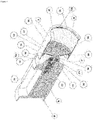
- Figure 1 / 9 corresponds to a lower perspective view of an atmospheric control valve for a refrigerated container according to the invention.
- Figure 2 / 9 corresponds to the lower front view of the atmosphere control valve according to the invention.
- Figure 3 / 9 corresponds to a lateral cross-sectional view, according to cut A-A of figure 1 / 9 , of the invention's atmospheric control valve.
- Figure 4 / 9 is a cross-section perspective view according to the A-A cut of Figure 1 / 9 , of the invention's atmospheric control valve.
- Figure 5 / 9 is a top perspective view of the parts on the back of the invention's atmospheric control valve.
- Figure 6 / 9 corresponds to three groups of figures: The top group shows a front and rear perspective view of the gas sensor cover of the invention's atmospheric control valve.
- the middle group shows a front and rear perspective view of the body of the invention's atmospheric control valve.
- the lower group shows a front and rear view of the front cover of the invention's atmospheric control valve.
- Figure 7 / 9 corresponds to two groups of figures:
- the diagram on the left shows the positional relationship of the shaft (20) with all the parts that operate on this shaft.
- the rear (4), in contact with the lid compartment, also features the connector plug (50), which connects the device's motherboard with other devices and appliances outside the atmospheric control valve device.
- Figure 8 / 9 shows a partial view of the pieces in the atmospheric control valve device. This figure also shows the following specifications:
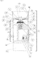
- Figure 9/9 shows a perspective top view of a prior art device, where an atmospheric control valve with high mechanical complexity and high energy consumption is depicted.
- the invention corresponds to an atmospheric control valve device (1) that is part of an atmospheric control system for a refrigerated cargo container, for the transport of perishable cargo such as fruit.
- This valve device has an elongated cylindrical shape, as shown in Figure 1 / 9 .
- the cylindrical body (2) has a front face or end (3), a rear face or end (4), an upper portion of the cylindrical body (5) forming an elongated upper semicircle, and a lower portion of the cylindrical body (6) forming an elongated lower semicircle.
- These body portions (5, 6) form the cylindrical body of the atmospheric control valve device (1).
- the upper part of the cylindrical body (5) comprising the upper part of the front end (3) and the upper part of the rear end (4), is made of one piece.
- the lower part of the cylindrical body (6) comprising the lower part of the front end (3) and the lower part of the rear end (4) are also made of one piece.
- These two parts (5) and (6) are joined by 4 bolts, which have a recess in their respective positions within the cylindrical body so that the bolts can be more easily handled during assembly or disassembly.
- the connection between these two parts (5) and (6) is separated by a rubber gasket (45) in order to keep all the elements contained in these parts isolated.
- the atmospheric control valve device (1) has guide troughs (46) along its body, which allow the device to be correctly positioned.
- the atmospheric control valve device (1) has a front cover (7) (shown in detail in Figure 2 /9), which is inserted into a front chamber (8) (shown in Figures 3 / 9 and 4 /9).
- This cover is inserted into the front end (3) of the atmospheric control valve device (1).
- This front end (3) has a recess (9) in its outer surface (10), which serves as a means to retain a perimeter o-ring (11), which fits in the recess (9) of the outer surface (10) of the device's front face (3).
- This recess (9) produces a flange (13) inside the front chamber (8), surrounding the entire circular perimeter of the inner surface of the device's front face (12), which allows the front cover (7) to be adjusted and attached to the front end of the device (3).
- the front cover (7) has a number of front openings (14) that allow flows of air and such gases to enter or exit from the outside of the container.
- this front cover (7) allows handling the atmospheric control valve device (1), so that it can be introduced or removed from and to its operating position.
- a series of grooves (14a) are positioned in the lateral contour of the front cover (7) that, together with additional grooves (12a) arranged in the inner perimeter of the front face of the device (12), anchor the part to the device's edge.
- Both grooves (14a and 12a) are positioned midway across the horizontal plane of the device, between the upper and lower portions of the cylindrical body (5, 6).
- the stability uprights (49) two points that stabilize the front cover (7), anchoring it under the guide trough (46) on the inner surface of the front face (12).
- the orifice (8) is deep enough for there to be a chamber behind the cover (7), limited by an external recess (15) in the circumferential perimeter of the outer surface (10) of the valve body's upper (5) and lower portions (6), creating an inner seat (16) on the inner surface (12) of the valve device's front face.
- This seat is at the bottom of the orifice (8), and is used to support a valve element (17).
- the seat (16) has a rubber seal for the seat and the shaft (23) on the face opposite to the valve element's body (18), which will fit part of the valve element body's rear face (18).
- the valve body (18) has a relatively smaller diameter than the internal diameter of the orifice (8).
- the solid body (18) of the valve element (17) contains a seal (19) on its rear face and to the side of the valve body's center, which may be made of rubber, partly surrounding the rear part of the valve body (18) of the valve element (17). It is placed around an shaft (20) from the center of the body (18) of the valve element (17), so that the edge of the rear seal of the valve element's body (19) remains next to the edge of the rubber seal (23) of the seat (16).
- the shaft (20) of the valve element (17) protrudes from the body (18) towards the bottom of the valve body, and is connected to an elastic part (21) located inside an enclosing chamber. The elastic piece finally separates the compartment where the electronics are located from the area where the air flows circulate.
- the shaft (20) of the valve element crosses the elastic part (21) through its center connecting it by one end to a solenoid (22).
- both the upper and lower parts of the cylindrical body (5 and 6) contain a flange recess (48) to mount the flanges (47) so that they can move without bumping into any other part of the device.
- valve element (17) On the outside it comprises the valve element body (18) and the rear seals of the valve element body (19). On the inside, and through the valve element body's (18) center, is a clamping bolt (17b) and a spring (17a). These internal elements anchor and provide flexibility to the connection between the valve element body (18) and the shaft (20), which is in turn anchored to the solenoid (22).
- the valve body (18) of the valve element (17) is set up in such a way that the rear of the valve body (18) shuts a first upper flow duct (24) that is formed in the upper part (5) of the valve body and that extends from the edge of the seat (16) to the rear edge of the upper flow duct opening (25a) on the upper part (5) of the body, where there is an upper flow duct opening (25).
- a second lower flow duct (26) is formed at the bottom (6) of the valve body, extending from the edge of the seat (16) to the rear edge of the lower flow duct opening (27a) at the bottom (6) of the body, where there is a lower flow duct opening (27).
- the recess that houses the elastic part (21) that is attached to the shaft (20) of the valve element (17) includes a central orifice (28) where the shaft (20) passes through to the body (18) of the valve element (17).
- This recess and central orifice (28) are formed by a central wall (29) that surrounds the recess and forms part of the wall that comprises the lower and upper flow ducts (24, 26).
- This central wall (29) shapes a central seat (30) made up of a wall surrounding the shaft (20), so that the central seat (30) comprises a rubber seal of the seat and the shaft (23) whose edge coincides with the edge of the seal (19) of the valve element's body (18).
- This set of elements and arrangement of the front portion of the valve body forms a first air exchange area, and the rear of the valve body forms a stagnation area.
- the stagnant area which is formed by the rear portion of the valve element body (18), comprises a rear chamber (31) at the rear edge of the upper flow opening (25a) and at the rear edge of the lower flow opening (27a) in the body portions (5, 6) respectively, as shown in Figure 3 / 9 .
- Two sub-zones are formed in this rear chamber (31): the battery compartment (32) and the electronics compartment (34).
- the battery compartment (32) houses a battery (35), which allows the equipment to operate autonomously.
- the electronics compartment (34) houses a number of electronic and electrical circuits, elements and sensors inside the body, which allow the valve to operate.
- the solenoid stem 51
- a processor which in turn moves the solenoid (22), opening and closing the valve element body (18) in order to control the container's atmosphere.
- the position of the sensors was designed to be representative in the detection of gases.
- the sensors are in turn protected on the surface by a sensor protection seal (52) and in particular by a gas sensor cover (44), which has two side vents (41) within its structure that allow the passage of gases from the container to the sensors.
- a connector plug (50) that projects into the area near the lid, used to optionally connect external modules that are not part of the atmosphere control valve device and that add other functions to the refrigerated container's atmospheric control, including a CO2 scrubber.
- the battery compartment (32) is protected by a seal cover (33) and anchored by two rubber bolts (37), holding the battery (35) in place, while the battery rubber (36) provides an airtight seal for the battery chamber.
- the elastic piece (21) directs the movement of the solenoid (22) towards the body of the valve element (18), separating the stagnant area from the flow passage compartment (formed by the upper flow duct (24), the upper flow duct opening (25), the lower flow duct (26), the lower flow duct opening (27), the central orifice (28)), all in a unified form and in a single piece, which strengthens and solidifies the valve setup.
- the setup of the two ducts and the valve element's (17) operation provide for a valve with two flow exchange openings for gases and/or air, formed by the ducts (24, 26). They operate as air inlets or outlets, respectively, and do not depend on a specific position to operate, letting the valve work in two directions.
- the valve element (17) seal is formed by the seals (19 and 23), used to efficiently open and close the solenoid.
- the airtight seal added to the pressure differences generated by the thermal gradient captured by the openings (25) and (27) make the solenoid require less force to operate the valve element (17), thus achieving a greater air transfer area with less force, and therefore less effort and a lesser failure probability.
- valve element (17) comprises a single mechanism that operates both the inlet and outlet flow for air and/or gases, simultaneously by means of a single solenoid, allows reducing energy consumption. This allows the system to be electrically powered with a battery (35), providing autonomy to the atmospheric control valve device of the invention.
- the shape of the cavities or flow ducts (24, 26) lean from their opening extending towards the center of the valve element's body (18) facing towards its front, where the central seat and rubber seal of the seat and the shaft (30, 23) are located. These lean to the front, toward the outside surface of the valve's body.
- the inner seat and the rubber seals of the seat and shaft (16, 23) of the inner surface of the valve element's body (18) follow the same direction and inclination of the inner seat and rubber seal of the seat and shaft.
- the rear of the valve element's body (18) has a "V" shape set towards the interior of the body and towards the bottom of the valve body (17).
- the inlet and outlet flows are separate, coming from separate compartments.
- the angle of these elements and components in the center of the valve element's body (18) also provide an intermediate division to the valve, allowing differentiated flows of gas and/or air, as shown in Figure 6 / 9 .
- the shape, setup and operation of the present invention's atmospheric control valve device allows for easy manipulation, saving space, energy and parts. This is achieved by providing a small, automatic, compact, unique, robust, autonomous, manipulable and efficient valve device, which incorporates all electrical and electronic accessories, as well as the sensor elements inside its body, avoiding the use of cables and other devices outside the valve device's body or as accessories attached to the valve or controller in order to form the atmospheric control system, which can be easily damaged.
- This atmosphere control valve device requires minimal intervention of the refrigerated container, thus reducing implementation, operation and maintenance costs, facilitating its modification.
Landscapes
- Engineering & Computer Science (AREA)
- Chemical & Material Sciences (AREA)
- Life Sciences & Earth Sciences (AREA)
- Food Science & Technology (AREA)
- Polymers & Plastics (AREA)
- Mechanical Engineering (AREA)
- Chemical Kinetics & Catalysis (AREA)
- General Chemical & Material Sciences (AREA)
- Nutrition Science (AREA)
- Health & Medical Sciences (AREA)
- Zoology (AREA)
- Wood Science & Technology (AREA)
- General Engineering & Computer Science (AREA)
- Thermal Sciences (AREA)
- Physics & Mathematics (AREA)
- Combustion & Propulsion (AREA)
- Pest Control & Pesticides (AREA)
- Devices That Are Associated With Refrigeration Equipment (AREA)
- Primary Cells (AREA)
- Magnetically Actuated Valves (AREA)
- Details Of Valves (AREA)
Applications Claiming Priority (2)
| Application Number | Priority Date | Filing Date | Title |
|---|---|---|---|
| CL2016000948A CL2016000948A1 (es) | 2016-04-20 | 2016-04-20 | Dispositivo de válvula controladora de atmósfera, de mínima intervención en su instalación en contenedores refrigerados, autosuficiente, compacto, reutilizable que comprende un cuerpo con una forma cilíndrica alargada, que a su vez comprende una zona de batería dentro del cuerpo, una zona electrónica, una zona de manipulación dentro del cuerpo, una zona del tapón dentro del cuerpo y una zona de intercambio de gases. |
| PCT/CL2016/000037 WO2017181298A1 (es) | 2016-04-20 | 2016-07-18 | Dispositivo para el control de atmosfera, de minima intervencion en su instalacion en contenedores refrigerados, autosuficiente, compacto, reutilizable porque comprende un cuerpo cilindrico alargado, una zona de la bateria, una zona electronica, una zona de manipulacion, una zona del tapon y una zona de intercambio de gases |
Publications (3)
| Publication Number | Publication Date |
|---|---|
| EP3446568A1 EP3446568A1 (en) | 2019-02-27 |
| EP3446568A4 EP3446568A4 (en) | 2019-12-04 |
| EP3446568B1 true EP3446568B1 (en) | 2021-12-15 |
Family
ID=59858288
Family Applications (1)
| Application Number | Title | Priority Date | Filing Date |
|---|---|---|---|
| EP16898889.7A Active EP3446568B1 (en) | 2016-04-20 | 2016-07-18 | Atmosphere valve control device for installation in refrigerated containers |
Country Status (8)
| Country | Link |
|---|---|
| US (1) | US11033038B2 (es) |
| EP (1) | EP3446568B1 (es) |
| CL (1) | CL2016000948A1 (es) |
| CO (1) | CO2018008984A2 (es) |
| MX (1) | MX2018012209A (es) |
| PE (1) | PE20181872A1 (es) |
| WO (1) | WO2017181298A1 (es) |
| ZA (1) | ZA201806532B (es) |
Families Citing this family (2)
| Publication number | Priority date | Publication date | Assignee | Title |
|---|---|---|---|---|
| SE2050035A1 (en) * | 2020-01-16 | 2021-07-17 | Holmbergs Safety System Holding Ab | Belt buckle for a safety belt in a child restraint system |
| CN111806892B (zh) * | 2020-07-14 | 2022-02-01 | 重庆蔷薇药业有限公司 | 一种可避免蛀虫具有保护效果的中药用储蓄装置及方法 |
Family Cites Families (9)
| Publication number | Priority date | Publication date | Assignee | Title |
|---|---|---|---|---|
| US5872721A (en) * | 1990-04-11 | 1999-02-16 | Transfresh Corporation | Monitor-control systems and methods for monitoring and controlling atmospheres in containers for respiring perishables |
| US5623105A (en) * | 1992-10-21 | 1997-04-22 | Prolong Systems, Inc. | Oxygen/carbon dioxide sensor and controller for a refrigerated controlled atmosphere shipping container |
| EP1175353B1 (en) * | 1998-10-19 | 2006-12-20 | Mitsubishi Australia Ltd | Apparatus for controlled venting of a chamber |
| EP1053945B1 (en) * | 1999-05-21 | 2003-10-29 | Aracaria B.V. | A hand-held suction pump |
| US20080028730A1 (en) * | 2006-08-02 | 2008-02-07 | Savicki Alan F | Device and Method For Evacuating A Storage Bag |
| US8177883B2 (en) * | 2006-08-09 | 2012-05-15 | Maersk Container Industri A/S | Container with controlled atmosphere |
| ES2718304T3 (es) * | 2012-11-01 | 2019-07-01 | Mitsubishi Australia Ltd | Mejoras en el control de la composición de gas dentro de un contenedor |
| JP5943106B1 (ja) * | 2015-02-27 | 2016-06-29 | ダイキン工業株式会社 | ガス供給装置及びそれを備えたコンテナ用冷凍装置 |
| ES2846889T3 (es) * | 2015-07-27 | 2021-07-30 | Avcatech Laboratories Pty Ltd | Monitorización del estado de productos dentro de contenedores de transporte |
-
2016
- 2016-04-20 CL CL2016000948A patent/CL2016000948A1/es unknown
- 2016-07-18 EP EP16898889.7A patent/EP3446568B1/en active Active
- 2016-07-18 WO PCT/CL2016/000037 patent/WO2017181298A1/es active Application Filing
- 2016-07-18 US US16/094,558 patent/US11033038B2/en active Active
- 2016-07-18 PE PE2018001963A patent/PE20181872A1/es unknown
- 2016-07-18 MX MX2018012209A patent/MX2018012209A/es unknown
-
2018
- 2018-08-28 CO CONC2018/0008984A patent/CO2018008984A2/es unknown
- 2018-10-02 ZA ZA2018/06532A patent/ZA201806532B/en unknown
Also Published As
| Publication number | Publication date |
|---|---|
| WO2017181298A1 (es) | 2017-10-26 |
| US20190098910A1 (en) | 2019-04-04 |
| PE20181872A1 (es) | 2018-12-05 |
| CO2018008984A2 (es) | 2018-11-13 |
| EP3446568A4 (en) | 2019-12-04 |
| US11033038B2 (en) | 2021-06-15 |
| EP3446568A1 (en) | 2019-02-27 |
| ZA201806532B (en) | 2020-03-25 |
| MX2018012209A (es) | 2018-12-17 |
| CL2016000948A1 (es) | 2017-07-14 |
Similar Documents
| Publication | Publication Date | Title |
|---|---|---|
| EP2078458B1 (en) | Device for controlling the gas medium inside a container | |
| JP5971296B2 (ja) | コンテナ用冷凍装置 | |
| EP3446568B1 (en) | Atmosphere valve control device for installation in refrigerated containers | |
| JP2016512952A (ja) | 調整及び制御雰囲気システム及び方法 | |
| EP3399262B1 (en) | Method for controlling concentration of gas in crisper drawer | |
| EP1631150A1 (en) | An apparatus for controlling the composition of gases within a container | |
| US11647761B2 (en) | Filter unit, gas supply device, inside air conditioner, and cooling device for container | |
| CN107250693A (zh) | 集装箱用制冷装置 | |
| US20230397581A1 (en) | Devices, systems, and methods for transporting live insects | |
| US20230192395A1 (en) | Air composition adjustment device, refrigeration apparatus, and transportation container | |
| EP2725914A1 (en) | Controlled atmosphere sea van container including carbon dioxide container including carbon dioxide scrubber curtain | |
| EP3811770B1 (en) | Storage system | |
| JP6459355B2 (ja) | 庫内空気調節装置及びそれを備えたコンテナ用冷凍装置 | |
| US11137191B2 (en) | Gas supply device, device for controlling inside air, and refrigeration device for container | |
| CN107249341B (zh) | 供气装置及包括该供气装置的集装箱用制冷装置 | |
| KR20190099516A (ko) | 상자 내 공기 조성 변경으로 신선도가 연장된 상태로 생산물을 보관할 수 있는 야채 상자 | |
| EP3437487B1 (en) | Atmosphere control for cargo storage spaces | |
| EP3486191A1 (en) | Hatch device comprising a main body supporting a flow guiding part | |
| AU2019215804B2 (en) | Transport container with gas selective membrane exhaust | |
| US20110296984A1 (en) | Carbon dioxide (co2) scrubber for controlled atmosphere sea van container | |
| KR200280723Y1 (ko) | 수서생물 호흡측정용기 | |
| US5163361A (en) | Pneumatic variable capacity fumigation system | |
| CN217295565U (zh) | 保温箱盖和保温箱 | |
| CN216402733U (zh) | 皮带罩 | |
| CN106070565A (zh) | 气调罐 |
Legal Events
| Date | Code | Title | Description |
|---|---|---|---|
| STAA | Information on the status of an ep patent application or granted ep patent |
Free format text: STATUS: THE INTERNATIONAL PUBLICATION HAS BEEN MADE |
|
| PUAI | Public reference made under article 153(3) epc to a published international application that has entered the european phase |
Free format text: ORIGINAL CODE: 0009012 |
|
| STAA | Information on the status of an ep patent application or granted ep patent |
Free format text: STATUS: REQUEST FOR EXAMINATION WAS MADE |
|
| 17P | Request for examination filed |
Effective date: 20181115 |
|
| AK | Designated contracting states |
Kind code of ref document: A1 Designated state(s): AL AT BE BG CH CY CZ DE DK EE ES FI FR GB GR HR HU IE IS IT LI LT LU LV MC MK MT NL NO PL PT RO RS SE SI SK SM TR |
|
| AX | Request for extension of the european patent |
Extension state: BA ME |
|
| STAA | Information on the status of an ep patent application or granted ep patent |
Free format text: STATUS: REQUEST FOR EXAMINATION WAS MADE |
|
| DAV | Request for validation of the european patent (deleted) | ||
| DAX | Request for extension of the european patent (deleted) | ||
| A4 | Supplementary search report drawn up and despatched |
Effective date: 20191107 |
|
| RIC1 | Information provided on ipc code assigned before grant |
Ipc: F25D 11/00 20060101ALI20191031BHEP Ipc: B65D 88/74 20060101ALI20191031BHEP Ipc: A23L 3/34 20060101ALI20191031BHEP Ipc: F25D 17/04 20060101ALI20191031BHEP Ipc: A23B 7/04 20060101AFI20191031BHEP Ipc: A23B 7/14 20060101ALI20191031BHEP |
|
| REG | Reference to a national code |
Ref country code: DE Ref legal event code: R079 Ref document number: 602016067516 Country of ref document: DE Free format text: PREVIOUS MAIN CLASS: A23B0007000000 Ipc: F25D0011000000 |
|
| RIC1 | Information provided on ipc code assigned before grant |
Ipc: F25D 11/00 20060101AFI20210422BHEP Ipc: F25D 17/04 20060101ALI20210422BHEP Ipc: A23B 7/148 20060101ALI20210422BHEP Ipc: A23L 3/00 20060101ALI20210422BHEP |
|
| GRAP | Despatch of communication of intention to grant a patent |
Free format text: ORIGINAL CODE: EPIDOSNIGR1 |
|
| STAA | Information on the status of an ep patent application or granted ep patent |
Free format text: STATUS: GRANT OF PATENT IS INTENDED |
|
| INTG | Intention to grant announced |
Effective date: 20210715 |
|
| GRAS | Grant fee paid |
Free format text: ORIGINAL CODE: EPIDOSNIGR3 |
|
| GRAA | (expected) grant |
Free format text: ORIGINAL CODE: 0009210 |
|
| STAA | Information on the status of an ep patent application or granted ep patent |
Free format text: STATUS: THE PATENT HAS BEEN GRANTED |
|
| AK | Designated contracting states |
Kind code of ref document: B1 Designated state(s): AL AT BE BG CH CY CZ DE DK EE ES FI FR GB GR HR HU IE IS IT LI LT LU LV MC MK MT NL NO PL PT RO RS SE SI SK SM TR |
|
| REG | Reference to a national code |
Ref country code: GB Ref legal event code: FG4D Ref country code: CH Ref legal event code: EP |
|
| REG | Reference to a national code |
Ref country code: DE Ref legal event code: R096 Ref document number: 602016067516 Country of ref document: DE |
|
| REG | Reference to a national code |
Ref country code: IE Ref legal event code: FG4D |
|
| REG | Reference to a national code |
Ref country code: AT Ref legal event code: REF Ref document number: 1455766 Country of ref document: AT Kind code of ref document: T Effective date: 20220115 |
|
| REG | Reference to a national code |
Ref country code: NL Ref legal event code: FP |
|
| REG | Reference to a national code |
Ref country code: LT Ref legal event code: MG9D |
|
| PG25 | Lapsed in a contracting state [announced via postgrant information from national office to epo] |
Ref country code: RS Free format text: LAPSE BECAUSE OF FAILURE TO SUBMIT A TRANSLATION OF THE DESCRIPTION OR TO PAY THE FEE WITHIN THE PRESCRIBED TIME-LIMIT Effective date: 20211215 Ref country code: LT Free format text: LAPSE BECAUSE OF FAILURE TO SUBMIT A TRANSLATION OF THE DESCRIPTION OR TO PAY THE FEE WITHIN THE PRESCRIBED TIME-LIMIT Effective date: 20211215 Ref country code: FI Free format text: LAPSE BECAUSE OF FAILURE TO SUBMIT A TRANSLATION OF THE DESCRIPTION OR TO PAY THE FEE WITHIN THE PRESCRIBED TIME-LIMIT Effective date: 20211215 Ref country code: BG Free format text: LAPSE BECAUSE OF FAILURE TO SUBMIT A TRANSLATION OF THE DESCRIPTION OR TO PAY THE FEE WITHIN THE PRESCRIBED TIME-LIMIT Effective date: 20220315 |
|
| REG | Reference to a national code |
Ref country code: AT Ref legal event code: MK05 Ref document number: 1455766 Country of ref document: AT Kind code of ref document: T Effective date: 20211215 |
|
| PG25 | Lapsed in a contracting state [announced via postgrant information from national office to epo] |
Ref country code: SE Free format text: LAPSE BECAUSE OF FAILURE TO SUBMIT A TRANSLATION OF THE DESCRIPTION OR TO PAY THE FEE WITHIN THE PRESCRIBED TIME-LIMIT Effective date: 20211215 Ref country code: NO Free format text: LAPSE BECAUSE OF FAILURE TO SUBMIT A TRANSLATION OF THE DESCRIPTION OR TO PAY THE FEE WITHIN THE PRESCRIBED TIME-LIMIT Effective date: 20220315 Ref country code: LV Free format text: LAPSE BECAUSE OF FAILURE TO SUBMIT A TRANSLATION OF THE DESCRIPTION OR TO PAY THE FEE WITHIN THE PRESCRIBED TIME-LIMIT Effective date: 20211215 Ref country code: HR Free format text: LAPSE BECAUSE OF FAILURE TO SUBMIT A TRANSLATION OF THE DESCRIPTION OR TO PAY THE FEE WITHIN THE PRESCRIBED TIME-LIMIT Effective date: 20211215 |
|
| PG25 | Lapsed in a contracting state [announced via postgrant information from national office to epo] |
Ref country code: SM Free format text: LAPSE BECAUSE OF FAILURE TO SUBMIT A TRANSLATION OF THE DESCRIPTION OR TO PAY THE FEE WITHIN THE PRESCRIBED TIME-LIMIT Effective date: 20211215 Ref country code: SK Free format text: LAPSE BECAUSE OF FAILURE TO SUBMIT A TRANSLATION OF THE DESCRIPTION OR TO PAY THE FEE WITHIN THE PRESCRIBED TIME-LIMIT Effective date: 20211215 Ref country code: RO Free format text: LAPSE BECAUSE OF FAILURE TO SUBMIT A TRANSLATION OF THE DESCRIPTION OR TO PAY THE FEE WITHIN THE PRESCRIBED TIME-LIMIT Effective date: 20211215 Ref country code: PT Free format text: LAPSE BECAUSE OF FAILURE TO SUBMIT A TRANSLATION OF THE DESCRIPTION OR TO PAY THE FEE WITHIN THE PRESCRIBED TIME-LIMIT Effective date: 20220418 Ref country code: ES Free format text: LAPSE BECAUSE OF FAILURE TO SUBMIT A TRANSLATION OF THE DESCRIPTION OR TO PAY THE FEE WITHIN THE PRESCRIBED TIME-LIMIT Effective date: 20211215 Ref country code: EE Free format text: LAPSE BECAUSE OF FAILURE TO SUBMIT A TRANSLATION OF THE DESCRIPTION OR TO PAY THE FEE WITHIN THE PRESCRIBED TIME-LIMIT Effective date: 20211215 Ref country code: CZ Free format text: LAPSE BECAUSE OF FAILURE TO SUBMIT A TRANSLATION OF THE DESCRIPTION OR TO PAY THE FEE WITHIN THE PRESCRIBED TIME-LIMIT Effective date: 20211215 |
|
| PG25 | Lapsed in a contracting state [announced via postgrant information from national office to epo] |
Ref country code: PL Free format text: LAPSE BECAUSE OF FAILURE TO SUBMIT A TRANSLATION OF THE DESCRIPTION OR TO PAY THE FEE WITHIN THE PRESCRIBED TIME-LIMIT Effective date: 20211215 Ref country code: AT Free format text: LAPSE BECAUSE OF FAILURE TO SUBMIT A TRANSLATION OF THE DESCRIPTION OR TO PAY THE FEE WITHIN THE PRESCRIBED TIME-LIMIT Effective date: 20211215 |
|
| REG | Reference to a national code |
Ref country code: DE Ref legal event code: R097 Ref document number: 602016067516 Country of ref document: DE |
|
| PG25 | Lapsed in a contracting state [announced via postgrant information from national office to epo] |
Ref country code: IS Free format text: LAPSE BECAUSE OF FAILURE TO SUBMIT A TRANSLATION OF THE DESCRIPTION OR TO PAY THE FEE WITHIN THE PRESCRIBED TIME-LIMIT Effective date: 20220415 |
|
| PLBE | No opposition filed within time limit |
Free format text: ORIGINAL CODE: 0009261 |
|
| STAA | Information on the status of an ep patent application or granted ep patent |
Free format text: STATUS: NO OPPOSITION FILED WITHIN TIME LIMIT |
|
| PG25 | Lapsed in a contracting state [announced via postgrant information from national office to epo] |
Ref country code: DK Free format text: LAPSE BECAUSE OF FAILURE TO SUBMIT A TRANSLATION OF THE DESCRIPTION OR TO PAY THE FEE WITHIN THE PRESCRIBED TIME-LIMIT Effective date: 20211215 Ref country code: AL Free format text: LAPSE BECAUSE OF FAILURE TO SUBMIT A TRANSLATION OF THE DESCRIPTION OR TO PAY THE FEE WITHIN THE PRESCRIBED TIME-LIMIT Effective date: 20211215 |
|
| 26N | No opposition filed |
Effective date: 20220916 |
|
| PG25 | Lapsed in a contracting state [announced via postgrant information from national office to epo] |
Ref country code: SI Free format text: LAPSE BECAUSE OF FAILURE TO SUBMIT A TRANSLATION OF THE DESCRIPTION OR TO PAY THE FEE WITHIN THE PRESCRIBED TIME-LIMIT Effective date: 20211215 |
|
| PG25 | Lapsed in a contracting state [announced via postgrant information from national office to epo] |
Ref country code: MC Free format text: LAPSE BECAUSE OF FAILURE TO SUBMIT A TRANSLATION OF THE DESCRIPTION OR TO PAY THE FEE WITHIN THE PRESCRIBED TIME-LIMIT Effective date: 20211215 |
|
| REG | Reference to a national code |
Ref country code: CH Ref legal event code: PL |
|
| PG25 | Lapsed in a contracting state [announced via postgrant information from national office to epo] |
Ref country code: LU Free format text: LAPSE BECAUSE OF NON-PAYMENT OF DUE FEES Effective date: 20220718 Ref country code: LI Free format text: LAPSE BECAUSE OF NON-PAYMENT OF DUE FEES Effective date: 20220731 Ref country code: CH Free format text: LAPSE BECAUSE OF NON-PAYMENT OF DUE FEES Effective date: 20220731 |
|
| PG25 | Lapsed in a contracting state [announced via postgrant information from national office to epo] |
Ref country code: IT Free format text: LAPSE BECAUSE OF FAILURE TO SUBMIT A TRANSLATION OF THE DESCRIPTION OR TO PAY THE FEE WITHIN THE PRESCRIBED TIME-LIMIT Effective date: 20211215 |
|
| PG25 | Lapsed in a contracting state [announced via postgrant information from national office to epo] |
Ref country code: IE Free format text: LAPSE BECAUSE OF NON-PAYMENT OF DUE FEES Effective date: 20220718 |
|
| PGFP | Annual fee paid to national office [announced via postgrant information from national office to epo] |
Ref country code: GB Payment date: 20230727 Year of fee payment: 8 |
|
| PGFP | Annual fee paid to national office [announced via postgrant information from national office to epo] |
Ref country code: FR Payment date: 20230725 Year of fee payment: 8 Ref country code: DE Payment date: 20230727 Year of fee payment: 8 Ref country code: BE Payment date: 20230727 Year of fee payment: 8 |
|
| PG25 | Lapsed in a contracting state [announced via postgrant information from national office to epo] |
Ref country code: HU Free format text: LAPSE BECAUSE OF FAILURE TO SUBMIT A TRANSLATION OF THE DESCRIPTION OR TO PAY THE FEE WITHIN THE PRESCRIBED TIME-LIMIT; INVALID AB INITIO Effective date: 20160718 |
|
| PG25 | Lapsed in a contracting state [announced via postgrant information from national office to epo] |
Ref country code: MK Free format text: LAPSE BECAUSE OF FAILURE TO SUBMIT A TRANSLATION OF THE DESCRIPTION OR TO PAY THE FEE WITHIN THE PRESCRIBED TIME-LIMIT Effective date: 20211215 Ref country code: CY Free format text: LAPSE BECAUSE OF FAILURE TO SUBMIT A TRANSLATION OF THE DESCRIPTION OR TO PAY THE FEE WITHIN THE PRESCRIBED TIME-LIMIT Effective date: 20211215 |
|
| PG25 | Lapsed in a contracting state [announced via postgrant information from national office to epo] |
Ref country code: TR Free format text: LAPSE BECAUSE OF FAILURE TO SUBMIT A TRANSLATION OF THE DESCRIPTION OR TO PAY THE FEE WITHIN THE PRESCRIBED TIME-LIMIT Effective date: 20211215 |
|
| PGFP | Annual fee paid to national office [announced via postgrant information from national office to epo] |
Ref country code: NL Payment date: 20240726 Year of fee payment: 9 |