EP3446549B1 - Systèmes et procédés de vérification d'authentifiants - Google Patents
Systèmes et procédés de vérification d'authentifiants Download PDFInfo
- Publication number
- EP3446549B1 EP3446549B1 EP17717667.4A EP17717667A EP3446549B1 EP 3446549 B1 EP3446549 B1 EP 3446549B1 EP 17717667 A EP17717667 A EP 17717667A EP 3446549 B1 EP3446549 B1 EP 3446549B1
- Authority
- EP
- European Patent Office
- Prior art keywords
- module
- data
- cloud
- computing device
- building server
- Prior art date
- Legal status (The legal status is an assumption and is not a legal conclusion. Google has not performed a legal analysis and makes no representation as to the accuracy of the status listed.)
- Active
Links
- 238000000034 method Methods 0.000 title claims description 121
- 230000006854 communication Effects 0.000 claims description 110
- 238000004891 communication Methods 0.000 claims description 110
- 238000012795 verification Methods 0.000 claims description 34
- 230000003287 optical effect Effects 0.000 claims description 14
- 230000004807 localization Effects 0.000 description 53
- 230000008569 process Effects 0.000 description 50
- 238000012544 monitoring process Methods 0.000 description 43
- 230000004044 response Effects 0.000 description 43
- 230000006870 function Effects 0.000 description 32
- 238000007726 management method Methods 0.000 description 29
- 238000003860 storage Methods 0.000 description 23
- 238000001228 spectrum Methods 0.000 description 18
- 239000004744 fabric Substances 0.000 description 16
- 230000037406 food intake Effects 0.000 description 15
- 230000007246 mechanism Effects 0.000 description 13
- 230000005855 radiation Effects 0.000 description 13
- 230000006399 behavior Effects 0.000 description 11
- 238000013475 authorization Methods 0.000 description 10
- 238000013480 data collection Methods 0.000 description 10
- 230000007613 environmental effect Effects 0.000 description 10
- 230000004397 blinking Effects 0.000 description 8
- 230000008859 change Effects 0.000 description 8
- 238000005265 energy consumption Methods 0.000 description 8
- 238000005516 engineering process Methods 0.000 description 8
- 230000003993 interaction Effects 0.000 description 8
- 230000001960 triggered effect Effects 0.000 description 8
- 238000004458 analytical method Methods 0.000 description 7
- 230000009471 action Effects 0.000 description 6
- 238000012545 processing Methods 0.000 description 6
- 230000000007 visual effect Effects 0.000 description 6
- 230000000694 effects Effects 0.000 description 5
- 238000005286 illumination Methods 0.000 description 5
- 238000012790 confirmation Methods 0.000 description 4
- 238000013499 data model Methods 0.000 description 4
- 238000013500 data storage Methods 0.000 description 4
- 239000012634 fragment Substances 0.000 description 4
- 238000009434 installation Methods 0.000 description 4
- 238000001429 visible spectrum Methods 0.000 description 4
- 241000282414 Homo sapiens Species 0.000 description 3
- OAICVXFJPJFONN-UHFFFAOYSA-N Phosphorus Chemical compound [P] OAICVXFJPJFONN-UHFFFAOYSA-N 0.000 description 3
- 238000013459 approach Methods 0.000 description 3
- 230000008901 benefit Effects 0.000 description 3
- 239000003795 chemical substances by application Substances 0.000 description 3
- 239000003086 colorant Substances 0.000 description 3
- 238000005401 electroluminescence Methods 0.000 description 3
- 230000002452 interceptive effect Effects 0.000 description 3
- 230000000644 propagated effect Effects 0.000 description 3
- 239000004065 semiconductor Substances 0.000 description 3
- 239000000243 solution Substances 0.000 description 3
- 238000012800 visualization Methods 0.000 description 3
- CURLTUGMZLYLDI-UHFFFAOYSA-N Carbon dioxide Chemical compound O=C=O CURLTUGMZLYLDI-UHFFFAOYSA-N 0.000 description 2
- 241000282412 Homo Species 0.000 description 2
- 230000002159 abnormal effect Effects 0.000 description 2
- 230000005540 biological transmission Effects 0.000 description 2
- 238000007405 data analysis Methods 0.000 description 2
- 238000010586 diagram Methods 0.000 description 2
- 230000005670 electromagnetic radiation Effects 0.000 description 2
- 230000003203 everyday effect Effects 0.000 description 2
- 239000000284 extract Substances 0.000 description 2
- 230000000977 initiatory effect Effects 0.000 description 2
- 230000033001 locomotion Effects 0.000 description 2
- 230000007774 longterm Effects 0.000 description 2
- 238000012423 maintenance Methods 0.000 description 2
- 239000000463 material Substances 0.000 description 2
- 238000012015 optical character recognition Methods 0.000 description 2
- 230000002085 persistent effect Effects 0.000 description 2
- 230000035755 proliferation Effects 0.000 description 2
- 238000012552 review Methods 0.000 description 2
- 238000012360 testing method Methods 0.000 description 2
- 238000012546 transfer Methods 0.000 description 2
- 238000013519 translation Methods 0.000 description 2
- 230000014616 translation Effects 0.000 description 2
- KKIMDKMETPPURN-UHFFFAOYSA-N 1-(3-(trifluoromethyl)phenyl)piperazine Chemical compound FC(F)(F)C1=CC=CC(N2CCNCC2)=C1 KKIMDKMETPPURN-UHFFFAOYSA-N 0.000 description 1
- 241000149788 Pseudophryne major Species 0.000 description 1
- 239000008186 active pharmaceutical agent Substances 0.000 description 1
- 238000003491 array Methods 0.000 description 1
- 238000012550 audit Methods 0.000 description 1
- 230000007175 bidirectional communication Effects 0.000 description 1
- 239000000872 buffer Substances 0.000 description 1
- 230000003139 buffering effect Effects 0.000 description 1
- 238000004422 calculation algorithm Methods 0.000 description 1
- 229910052799 carbon Inorganic materials 0.000 description 1
- 229910002092 carbon dioxide Inorganic materials 0.000 description 1
- 239000001569 carbon dioxide Substances 0.000 description 1
- 238000006243 chemical reaction Methods 0.000 description 1
- 238000004140 cleaning Methods 0.000 description 1
- 238000004590 computer program Methods 0.000 description 1
- 230000002354 daily effect Effects 0.000 description 1
- 238000012517 data analytics Methods 0.000 description 1
- 230000002950 deficient Effects 0.000 description 1
- 230000001934 delay Effects 0.000 description 1
- 238000011161 development Methods 0.000 description 1
- 230000018109 developmental process Effects 0.000 description 1
- 239000000835 fiber Substances 0.000 description 1
- 238000007519 figuring Methods 0.000 description 1
- 230000004907 flux Effects 0.000 description 1
- 229910052736 halogen Inorganic materials 0.000 description 1
- 150000002367 halogens Chemical class 0.000 description 1
- 230000036541 health Effects 0.000 description 1
- 238000010438 heat treatment Methods 0.000 description 1
- 230000006872 improvement Effects 0.000 description 1
- 238000002329 infrared spectrum Methods 0.000 description 1
- 238000002347 injection Methods 0.000 description 1
- 239000007924 injection Substances 0.000 description 1
- 230000010354 integration Effects 0.000 description 1
- 238000005304 joining Methods 0.000 description 1
- 238000010801 machine learning Methods 0.000 description 1
- 238000004519 manufacturing process Methods 0.000 description 1
- 239000000203 mixture Substances 0.000 description 1
- 238000012986 modification Methods 0.000 description 1
- 230000004048 modification Effects 0.000 description 1
- 230000036651 mood Effects 0.000 description 1
- 230000006855 networking Effects 0.000 description 1
- 230000008520 organization Effects 0.000 description 1
- 230000001151 other effect Effects 0.000 description 1
- 238000009428 plumbing Methods 0.000 description 1
- 229920000642 polymer Polymers 0.000 description 1
- 238000003825 pressing Methods 0.000 description 1
- 230000009979 protective mechanism Effects 0.000 description 1
- 238000011084 recovery Methods 0.000 description 1
- 230000000306 recurrent effect Effects 0.000 description 1
- 238000009877 rendering Methods 0.000 description 1
- 238000010079 rubber tapping Methods 0.000 description 1
- 230000001932 seasonal effect Effects 0.000 description 1
- 239000004984 smart glass Substances 0.000 description 1
- 238000007619 statistical method Methods 0.000 description 1
- 238000010998 test method Methods 0.000 description 1
- 238000012549 training Methods 0.000 description 1
- 238000013024 troubleshooting Methods 0.000 description 1
- 238000002211 ultraviolet spectrum Methods 0.000 description 1
Images


Classifications
-
- G—PHYSICS
- G06—COMPUTING; CALCULATING OR COUNTING
- G06F—ELECTRIC DIGITAL DATA PROCESSING
- G06F21/00—Security arrangements for protecting computers, components thereof, programs or data against unauthorised activity
- G06F21/30—Authentication, i.e. establishing the identity or authorisation of security principals
- G06F21/31—User authentication
- G06F21/33—User authentication using certificates
-
- G—PHYSICS
- G06—COMPUTING; CALCULATING OR COUNTING
- G06F—ELECTRIC DIGITAL DATA PROCESSING
- G06F21/00—Security arrangements for protecting computers, components thereof, programs or data against unauthorised activity
- G06F21/30—Authentication, i.e. establishing the identity or authorisation of security principals
- G06F21/31—User authentication
- G06F21/42—User authentication using separate channels for security data
- G06F21/43—User authentication using separate channels for security data wireless channels
-
- G—PHYSICS
- G06—COMPUTING; CALCULATING OR COUNTING
- G06F—ELECTRIC DIGITAL DATA PROCESSING
- G06F21/00—Security arrangements for protecting computers, components thereof, programs or data against unauthorised activity
- G06F21/30—Authentication, i.e. establishing the identity or authorisation of security principals
- G06F21/44—Program or device authentication
-
- H—ELECTRICITY
- H04—ELECTRIC COMMUNICATION TECHNIQUE
- H04L—TRANSMISSION OF DIGITAL INFORMATION, e.g. TELEGRAPHIC COMMUNICATION
- H04L63/00—Network architectures or network communication protocols for network security
- H04L63/08—Network architectures or network communication protocols for network security for authentication of entities
- H04L63/0876—Network architectures or network communication protocols for network security for authentication of entities based on the identity of the terminal or configuration, e.g. MAC address, hardware or software configuration or device fingerprint
-
- H—ELECTRICITY
- H04—ELECTRIC COMMUNICATION TECHNIQUE
- H04L—TRANSMISSION OF DIGITAL INFORMATION, e.g. TELEGRAPHIC COMMUNICATION
- H04L9/00—Cryptographic mechanisms or cryptographic arrangements for secret or secure communications; Network security protocols
- H04L9/32—Cryptographic mechanisms or cryptographic arrangements for secret or secure communications; Network security protocols including means for verifying the identity or authority of a user of the system or for message authentication, e.g. authorization, entity authentication, data integrity or data verification, non-repudiation, key authentication or verification of credentials
- H04L9/3215—Cryptographic mechanisms or cryptographic arrangements for secret or secure communications; Network security protocols including means for verifying the identity or authority of a user of the system or for message authentication, e.g. authorization, entity authentication, data integrity or data verification, non-repudiation, key authentication or verification of credentials using a plurality of channels
-
- H—ELECTRICITY
- H04—ELECTRIC COMMUNICATION TECHNIQUE
- H04W—WIRELESS COMMUNICATION NETWORKS
- H04W12/00—Security arrangements; Authentication; Protecting privacy or anonymity
- H04W12/06—Authentication
-
- H—ELECTRICITY
- H05—ELECTRIC TECHNIQUES NOT OTHERWISE PROVIDED FOR
- H05B—ELECTRIC HEATING; ELECTRIC LIGHT SOURCES NOT OTHERWISE PROVIDED FOR; CIRCUIT ARRANGEMENTS FOR ELECTRIC LIGHT SOURCES, IN GENERAL
- H05B47/00—Circuit arrangements for operating light sources in general, i.e. where the type of light source is not relevant
- H05B47/10—Controlling the light source
- H05B47/105—Controlling the light source in response to determined parameters
-
- H—ELECTRICITY
- H05—ELECTRIC TECHNIQUES NOT OTHERWISE PROVIDED FOR
- H05B—ELECTRIC HEATING; ELECTRIC LIGHT SOURCES NOT OTHERWISE PROVIDED FOR; CIRCUIT ARRANGEMENTS FOR ELECTRIC LIGHT SOURCES, IN GENERAL
- H05B47/00—Circuit arrangements for operating light sources in general, i.e. where the type of light source is not relevant
- H05B47/10—Controlling the light source
- H05B47/165—Controlling the light source following a pre-assigned programmed sequence; Logic control [LC]
-
- H—ELECTRICITY
- H05—ELECTRIC TECHNIQUES NOT OTHERWISE PROVIDED FOR
- H05B—ELECTRIC HEATING; ELECTRIC LIGHT SOURCES NOT OTHERWISE PROVIDED FOR; CIRCUIT ARRANGEMENTS FOR ELECTRIC LIGHT SOURCES, IN GENERAL
- H05B47/00—Circuit arrangements for operating light sources in general, i.e. where the type of light source is not relevant
- H05B47/10—Controlling the light source
- H05B47/175—Controlling the light source by remote control
- H05B47/19—Controlling the light source by remote control via wireless transmission
-
- H—ELECTRICITY
- H05—ELECTRIC TECHNIQUES NOT OTHERWISE PROVIDED FOR
- H05B—ELECTRIC HEATING; ELECTRIC LIGHT SOURCES NOT OTHERWISE PROVIDED FOR; CIRCUIT ARRANGEMENTS FOR ELECTRIC LIGHT SOURCES, IN GENERAL
- H05B47/00—Circuit arrangements for operating light sources in general, i.e. where the type of light source is not relevant
- H05B47/10—Controlling the light source
- H05B47/175—Controlling the light source by remote control
- H05B47/196—Controlling the light source by remote control characterised by user interface arrangements
- H05B47/1965—Controlling the light source by remote control characterised by user interface arrangements using handheld communication devices
-
- H—ELECTRICITY
- H05—ELECTRIC TECHNIQUES NOT OTHERWISE PROVIDED FOR
- H05B—ELECTRIC HEATING; ELECTRIC LIGHT SOURCES NOT OTHERWISE PROVIDED FOR; CIRCUIT ARRANGEMENTS FOR ELECTRIC LIGHT SOURCES, IN GENERAL
- H05B47/00—Circuit arrangements for operating light sources in general, i.e. where the type of light source is not relevant
- H05B47/20—Responsive to malfunctions or to light source life; for protection
-
- H—ELECTRICITY
- H05—ELECTRIC TECHNIQUES NOT OTHERWISE PROVIDED FOR
- H05B—ELECTRIC HEATING; ELECTRIC LIGHT SOURCES NOT OTHERWISE PROVIDED FOR; CIRCUIT ARRANGEMENTS FOR ELECTRIC LIGHT SOURCES, IN GENERAL
- H05B47/00—Circuit arrangements for operating light sources in general, i.e. where the type of light source is not relevant
- H05B47/10—Controlling the light source
- H05B47/175—Controlling the light source by remote control
- H05B47/19—Controlling the light source by remote control via wireless transmission
- H05B47/195—Controlling the light source by remote control via wireless transmission the transmission using visible or infrared light
Definitions
- the present disclosure is directed generally to monitoring and control of physical environments, such as indoor or outdoor spaces. More particularly, but not exclusively, various systems, methods and apparatuses disclosed herein relate to verifying credentials associated with various devices deployed in the physical environment
- LED lighting offers, among other benefits, the advantages of controllability, high energy conversion and optical efficiency, durability, and significantly lower operating costs. Additionally, more recent advances in controllable LED technology has resulted in a variety of efficient and robust full-spectrum lighting sources that can be easily controlled to create various lighting effects and scenes for use in theatrical, office or home settings.
- sensors are becoming smaller, cheaper and therefore more ubiquitous.
- environmental metrics e.g. natural illumination, noise, occupancy, temperature, humidity
- complex metrics such as resource and space usage, activity levels, intrusion, and mood, which may require the coordinated use of a various of sensor types.
- the data gathered may be sensitive image data or data from smart phones or tablets capable of identifying individuals and the activities they are engaged in.
- the gathering and processing of such data gives rise to issues of data privacy, which may become central to the proper functioning of a system for monitoring physical spaces. How such data needs to be anonymized and/or aggregated, who gets to view the raw or analyzed data, how the data is presented to avoid identifying particular individuals, how the data is securely transmitted from its source (e.g. sensors that gather the raw data) to its destination ( e.g . a cloud-based server or an app on an individual's smart phone) needs to be carefully considered and implemented.
- existing systems for monitoring space and resource usage have not developed comprehensive strategies to address such issues.
- space and resource usage data gathered from physical spaces needs to be accurately time-stamped, gathered with sufficient granularity, and processed in a timely manner in order to provide insights that may result in energy or other usage efficiencies.
- occupancy data that isn't appropriately time-stamped may not provide accurate information regarding when spaces such as meeting rooms or corridors are heavily used.
- delays in providing this data to an appropriate cloud server for analysis may, for example, lead to the failure to timely schedule maintenance in high traffic areas or positively affect the scheduling of such spaces in the near future ( e.g . by suggesting alternative corridors to direct flow of traffic).
- existing systems for monitoring space and resource usage have not developed comprehensive strategies to address such issues.
- a large number (and variety) of sensor devices would typically be required to perform the basic data generation.
- such facilities typically have a wide variety of appliances (e.g . printers, scanners, lighting devices), and monitoring their usage would also provide useful information regarding energy efficiency.
- appliances e.g . printers, scanners, lighting devices
- monitoring their usage would also provide useful information regarding energy efficiency. While these devices may all be able to connect to a network such as a local area network, the data they generate will likely be in a variety of formats. Accordingly, any system that is to use the information generated by all the devices present needs to be able to convert between the formats of data coming from these devices to one or more common formats that can be understood and processed by various data processing applications used by the system.
- Such systems need to have the capability to incorporate new devices without overwhelming any portion of the system.
- such systems need to be scalable in that they should be able to comfortably accommodate a growing number of devices and users, and consequently a growing amount of data generated, from a network bandwidth, installation efficiency, and data analysis standpoint.
- complex systems should to be able to manage errors without significant data loss. In other words, they should anticipate and minimize loss of data when hardware or software fails.
- Transport layer authentication is often implemented using credentials such as certificates or by performing operations using shared secrets (e.g. , pre-shared keys).
- a root certificate may be installed on one communicating peer. The root certificate may be used to verify a certificate chain.
- PKI Public Key Infrastructure
- PKI tends to be costly both financially and in terms of required expertise.
- US2013/0223279 A1 discloses a method for configuring a network device in a communication network using a mobile device.
- a sensor associated with the mobile device detects sensor information from the network device.
- the sensor information is indicative of configuration information associated with the network device.
- the configuration information is decoded based on the sensor information detected from the network device.
- the mobile device provides, to the network device, communication device credentials associated with an access point of the communication network to enable the network device to connect to the communication network via the access point based, at least in part, on the decoded configuration information.
- a computer-implemented method for verifying credentials includes the following operations: obtaining, at a computing device seeking to verify credentials of a lighting system controller, unverified credentials of the lighting system controller; transmitting, by the computing device to the lighting system controller via a first network communication channel, a request to verify the unverified credentials; transmitting, by the lighting system controller, credential-based data via a wired or wireless network; receiving, by another remote device, credential-based data via the wired or wireless network; receiving verification data at the computing device from the other remote device via a second network communication channel, wherein the second network communication channel is different than the first network communication channel; comparing, by the computing device, the unverified credentials to the verification data; verifying, by the computing device based on the comparing, that the unverified credentials are legitimate; based on the verifying, establishing, by the computing device, a lighting information communication channel between the computing device and the lighting system controller; and exchanging, by the computing device with the lighting system controller via the lighting information communication channel, data related to operation of one
- the second network communication channel may include an optical wireless communication channel, and the receiving may include detecting a modulated optical wireless signal at a light sensor of the computing device.
- the optical wireless communication channel may include a visible light communication channel.
- the verification data may be received from the other remote device, and the other remote device comprises a networked luminaire.
- the optical wireless communication channel may be implemented by the lighting system controller or the other remote device via a digital display device or via one or more LED-based indicator lights.
- the first network communication channel may include a radio frequency-based communication channel.
- the radio frequency-based communication channel may be implemented using Wi-Fi, ZigBee, or Z-Wave.
- the verification data may include a first hash of the unverified credentials generated by the lighting system controller or other remote device , and the comparing comprises comparing the first hash to a second hash of the unverified credentials generated by the computing device.
- the method may further include: setting, by the computing device, a timer; and rejecting, by the computing device, any verification data received after expiration of the timer.
- the method may further include: generating, by the computing device, a secret key based on information obtained from indicia provided on a surface of the lighting system controller; performing, by the computing device based on the secret key, a crypographic hash function to generate a first cryptographic hash function output; transmitting, by the computing device to the lighting system controller, the first cryptographic hash function output; receiving, by the computing device from the lighting system controller, a second cryptographic hash function output; and verifying, by the computing device, the second cryptographic hash function output.
- transmission, by the computing device to the lighting system controller of the request to verify the unverified credentials may be selectively performed based on an outcome of the verification of the second cryptographic hash function output.
- a lighting system comprising a lighting system controller, a computing device which is remote from the lighting system controller, and another remote device being a light source of the lighting system in the form of a luminaire or a smart light bulb, the lighting system further comprising one or more further light sources and one or more sensors and wherein the computing device and the lighting system controller are configured to perform a method such as one or more of the methods described herein.
- the term "LED” should be understood to include any electroluminescent diode or other type of carrier injection/junction-based system that is capable of generating radiation in response to an electric signal and/or acting as a photodiode.
- the term LED includes, but is not limited to, various semiconductor-based structures that emit light in response to current, light emitting polymers, organic light emitting diodes (OLEDs), electroluminescent strips, and the like.
- LED refers to light emitting diodes of all types (including semiconductor and organic light emitting diodes) that may be configured to generate radiation in one or more of the infrared spectrum, ultraviolet spectrum, and various portions of the visible spectrum (generally including radiation wavelengths from approximately 400 nanometers to approximately 700 nanometers).
- LEDs include, but are not limited to, various types of infrared LEDs, ultraviolet LEDs, red LEDs, blue LEDs, green LEDs, yellow LEDs, amber LEDs, orange LEDs, and white LEDs (discussed further below).
- LEDs may be configured and/or controlled to generate radiation having various bandwidths (e.g., full widths at half maximum, or FWHM) for a given spectrum (e.g., narrow bandwidth, broad bandwidth), and a variety of dominant wavelengths within a given general color categorization.
- bandwidths e.g., full widths at half maximum, or FWHM
- FWHM full widths at half maximum
- an LED configured to generate essentially white light may include a number of dies which respectively emit different spectra of electroluminescence that, in combination, mix to form essentially white light.
- a white light LED may be associated with a phosphor material that converts electroluminescence having a first spectrum to a different second spectrum.
- electroluminescence having a relatively short wavelength and narrow bandwidth spectrum "pumps" the phosphor material, which in turn radiates longer wavelength radiation having a somewhat broader spectrum.
- an LED does not limit the physical and/or electrical package type of an LED.
- an LED may refer to a single light emitting device having multiple dies that are configured to respectively emit different spectra of radiation (e.g ., that may or may not be individually controllable).
- an LED may be associated with a phosphor that is considered as an integral part of the LED (e.g ., some types of white LEDs).
- the term LED may refer to packaged LEDs, non-packaged LEDs, surface mount LEDs, chip-on-board LEDs, T-package mount LEDs, radial package LEDs, power package LEDs, LEDs including some type of encasement and/or optical element (e.g. , a diffusing lens), etc.
- light source should be understood to refer to any one or more of a variety of radiation sources, including, but not limited to, LED-based sources (including one or more LEDs as defined above).
- a given light source may be configured to generate electromagnetic radiation within the visible spectrum, outside the visible spectrum, or a combination of both.
- the terms “light” and “radiation” are used interchangeably herein.
- a light source may include as an integral component one or more filters (e.g. , color filters), lenses, or other optical components.
- filters e.g. , color filters
- an “illumination source” is a light source that is particularly configured to generate radiation having a sufficient intensity to effectively illuminate an interior or exterior space.
- “sufficient intensity” refers to sufficient radiant power in the visible spectrum generated in the space or environment (the unit “lumens” often is employed to represent the total light output from a light source in all directions, in terms of radiant power or "luminous flux”) to provide ambient illumination (i.e., light that may be perceived indirectly and that may be, for example, reflected off of one or more of a variety of intervening surfaces before being perceived in whole or in part).
- spectrum should be understood to refer to any one or more frequencies (or wavelengths) of radiation produced by one or more light sources. Accordingly, the term “spectrum” refers to frequencies (or wavelengths) not only in the visible range, but also frequencies (or wavelengths) in the infrared, ultraviolet, and other areas of the overall electromagnetic spectrum. Also, a given spectrum may have a relatively narrow bandwidth (e.g ., a FWHM having essentially few frequency or wavelength components) or a relatively wide bandwidth (several frequency or wavelength components having various relative strengths). It should also be appreciated that a given spectrum may be the result of a mixing of two or more other spectra (e.g. , mixing radiation respectively emitted from multiple light sources).
- color is used interchangeably with the term “spectrum.”
- the term “color” generally is used to refer primarily to a property of radiation that is perceivable by an observer (although this usage is not intended to limit the scope of this term). Accordingly, the terms “different colors” implicitly refer to multiple spectra having different wavelength components and/or bandwidths. It also should be appreciated that the term “color” may be used in connection with both white and non-white light.
- light fixture and “luminaire” are used interchangeably herein to refer to an implementation or arrangement of one or more lighting units in a particular form factor, assembly, or package.
- the term “lighting unit” is used herein to refer to an apparatus including one or more light sources of same or different types.
- a given lighting unit may have any one of a variety of mounting arrangements for the light source(s), enclosure/housing arrangements and shapes, and/or electrical and mechanical connection configurations. Additionally, a given lighting unit optionally may be associated with ( e.g ., include, be coupled to and/or packaged together with) various other components (e.g ., control circuitry) relating to the operation of the light source(s).
- LED-based lighting unit refers to a lighting unit that includes one or more LED-based light sources as discussed above, alone or in combination with other non LED-based light sources.
- a “multi-channel” lighting unit refers to an LED-based or non LED-based lighting unit that includes at least two light sources configured to respectively generate different spectrums of radiation, wherein each different source spectrum may be referred to as a "channel" of the multi-channel lighting unit.
- controller is used herein generally to describe various apparatus relating to the operation of one or more light sources.
- a controller can be implemented in numerous ways (e.g. , such as with dedicated hardware) to perform various functions discussed herein.
- a "processor” is one example of a controller which employs one or more microprocessors that may be programmed using software (e.g ., microcode) to perform various functions discussed herein.
- a controller may be implemented with or without employing a processor, and also may be implemented as a combination of dedicated hardware to perform some functions and a processor (e.g ., one or more programmed microprocessors and associated circuitry) to perform other functions. Examples of controller components that may be employed in various embodiments of the present disclosure include, but are not limited to, conventional microprocessors, application specific integrated circuits (ASICs), and field-programmable gate arrays (FPGAs).
- ASICs application specific integrated circuits
- FPGAs field-programmable gate arrays
- a processor or controller may be associated with one or more storage media (generically referred to herein as "memory,” e.g ., volatile and non-volatile computer memory such as RAM, PROM, EPROM, and EEPROM, floppy disks, compact disks, optical disks, magnetic tape, etc.).
- the storage media may be encoded with one or more programs that, when executed on one or more processors and/or controllers, perform at least some of the functions discussed herein.
- Various storage media may be fixed within a processor or controller or may be transportable, such that the one or more programs stored thereon can be loaded into a processor or controller so as to implement various aspects of the present invention discussed herein.
- program or “computer program” are used herein in a generic sense to refer to any type of computer code (e.g ., software or microcode) that can be employed to program one or more processors or controllers.
- one or more devices coupled to a network may serve as a controller for one or more other devices coupled to the network (e.g ., in a master/slave relationship).
- a networked environment may include one or more dedicated controllers that are configured to control one or more of the devices coupled to the network.
- multiple devices coupled to the network each may have access to data that is present on the communications medium or media; however, a given device may be "addressable" in that it is configured to selectively exchange data with (i.e., receive data from and/or transmit data to) the network, based, for example, on one or more particular identifiers (e.g. , "addresses") assigned to it.
- network refers to any interconnection of two or more devices (including controllers or processors) that facilitates the transport of information (e.g. for device control, data storage, data exchange, etc.) between any two or more devices and/or among multiple devices coupled to the network.
- various implementations of networks suitable for interconnecting multiple devices may include any of a variety of network topologies and employ any of a variety of communication protocols.
- any one connection between two devices may represent a dedicated connection between the two systems, or alternatively a non-dedicated connection. In addition to carrying information intended for the two devices, such a non-dedicated connection may carry information not necessarily intended for either of the two devices (e.g.
- communicatively coupled refers to two devices or other entities that are able to communicate with each other, either directly or indirectly, via intermediary entities ( e.g . other devices or a network). To be communicatively coupled, the two or more devices do not need to have a dedicated connection. They should simply be able to send and/or receive data from each other as necessary.
- user refers to any entity, human or artificial, that interacts with systems and methods described herein.
- the term includes, without limitation, occupants of a space such as an office worker or visitor, remote users of a space, a facility manager, a commissioning engineer, a building IT manager, a service engineer, and an installer.
- module or "application module” is used frequently to describe components herein. These terms are directed to software or firmware components, or a combination thereof.
- a single software/firmware module may be composed of one or more modules.
- a wholly software module may be executed on one or more processors that each reside on one or more devices.
- One or more components of the same module e.g . a frontend
- a single software module may contain one or more routines or functions.
- a software module may expose API usable by other modules. The terms are used to depict both computer code that is not being executed and executing code (e.g. a "runtime" module).
- System device is used throughout this specification. In various instances, it may mean devices such as a Gateway (wireless or otherwise) or a Building Server. It also applies to other devices used in physical environments such as sensors, lighting devices (e.g. luminaires, individual light sources), HVAC devices (e.g. heating devices, humidifiers, air conditioners), appliances (e.g . smart boards, fridges, cleaning appliances, dish washers, clothes washers/dryers, televisions), computing/communication devices (e.g. routers, smart phones, tablet computers), and various other sensic or lumic devices.
- lighting devices e.g. luminaires, individual light sources
- HVAC devices e.g. heating devices, humidifiers, air conditioners
- appliances e.g . smart boards, fridges, cleaning appliances, dish washers, clothes washers/dryers, televisions
- computing/communication devices e.g. routers, smart phones, tablet computers
- labeled arrows are used to depict communications between modules (e.g . module - module communication), devices (e.g. device - device communication), or some combination thereof (e.g. device - module communication).
- the module - module communication may be, for example, between a system application module in the cloud and a module in a building server or a module in a building server and another in a wireless gateway.
- the communication may involve function calls or other inter-process communication mechanisms.
- Such communications may be conducted directly by one module or device issuing a command or other signal to invoke an action or response from a module or device directly ( e.g .
- HTTPS HyperText Transfer Protocol
- MQTT Various communication protocols
- HTTPS is sometimes referred to as the communication protocol between, for example, a module in the Building Server and another module in the Gateway, or a Building Server and a Cloud.
- HTTP and MQTT for purposes of illustrating the exchange of data should not be considered limiting, and other communication protocols and techniques may be applied as well.
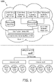
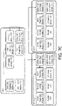
- Figure 1 illustrates a system 100A for cloud-based monitoring and control of a physical environment.
- the system includes a Building Server 100, Gateways 110A and 110B, System devices 101 through 106, a Computing cloud 115, System Energy Application Module 120, System Intake Application Module 130, System Project Application Module 140, User Management Application Module 150, System Map Application Module 160, a Projects Database 170A, a Data Database 170B, a Data Platform Module 180, and a Cloud Connectivity Module 190.
- Other embodiments of system 100A may include additional or fewer Building Servers, Gateways, System devices, Clouds, Database Modules, Cloud Connectivity Modules, and Data Platforms.
- Various components of system 100A are communicatively linked using the linkage lines depicted in Figure 1 .
- linkage line between two blocks or modules in the figure does not necessarily indicate the lack of communication capability between the blocks or modules.
- the term "physical structure” or “physical environment” as used herein refers to any building structure, whether or not freestanding, permanent, enclosed, or covered. This term includes for example, office, residential, recreational, educational, governmental, and commercial buildings and complexes, as well as parking lots and garages.
- the term "link” as used herein refers to any connection or component, whether physical or virtual, that enables the communication of information between at least two devices or system components.
- a link includes a wired or wireless communications connection, a radio frequency communications connection, and an optical communications connection.
- a link may also indicate a shared communication protocol, software or hardware interface, or remote method invocation or procedure calls.
- Cloud 115 is a typical cloud used for cloud computing. It provides shared data and processing resources to various devices that have access to it. It enables on demand access to a shared pool of computing resources such as networks, servers, storage, applications and services. Cloud 115 supports various cloud-based applications for System 100A, including System Energy Application Module 120, System Intake Application Module 130, System Project Application Module 140, User Management Application Module 150, System Map Application Module 160. These applications and the cloud infrastructure provide two key aspects of System 100A. First, an Installer who is responsible for installing a system like System 100A in a particular building or group of buildings does not need specialized training. Second, the desired behavior of system devices and resources in the physical environment being monitored and controlled is stored in the cloud itself, and is therefore easily configurable and downloadable.
- System Energy Application Module 120 is a cloud-based software application that may be used by lay end users of System 100A or by special Expert users of System 100A (e.g . facilities managers) to review reports or perform various tasks related to energy management. For example, a facilities manager may wish to check the average daily consumption in a particular week in order to determine whether a particular Monday had significantly higher energy consumption as compared to the average Monday, or to review data on the monthly energy consumption in the past year in order to determine seasonal changes in energy usage.
- System Energy Application Module 120 is therefore capable of presenting user interfaces to its users for the purpose of gathering information on what types of information the user would like to see presented, as well as for the purpose of presenting the necessary information in graphical ( e.g .
- System Intake Application Module 130 is a cloud-based software application that may be used by an intake engineer (hereinafter "Intaker") or other expert user of System 100A, to determine and/or establish lighting and/or other energy needs for one or more physical structures managed by System 100A.
- the Intaker may select one or more buildings from a Map view presented by Application Module 130.
- the Intake may further use Application Module 130 to load an existing floor plan for a particular floor of a selected building, and proceed to establish special areas (e.g . open plan office space, meeting rooms) and system devices (e.g .
- System Intake Application Module 130 also allows the Intaker to check the intake process to make sure, for example, that luminaires/light sources are properly allocated to designated areas, as well as properly allocated to respective gateways. This information from System Intake Application Module 130 may thereafter be used to populate the Projects Database 170A. System Intake Application Module 130 is discussed in more detail in the description associated with Figure 6 .
- System Project Application Module 140 is a cloud-based software application that may be used by Intakers, Experts, Installers, Administrators, and End Users associated with System 100A, to create and view Project hierarchies stored in Projects Database 170A.
- Application Module 140 also dispatches created and updated projects to other application modules such as the System Map Application Module 160, System Energy Application Module 120 or System Intake Application Module 130.
- a Project hierarchy may be created, for example, by having a user with appropriate privileges, such as an Administrator, specify an entity associated with the project ( e.g . an organization such as a Corporation). Thereafter, the Administrator might add physical sites associated with the entity ( e.g . the physical site in Amsterdam).
- the Administrator For each physical site or location, the Administrator might thereafter add one or more buildings, and their associated addresses and other identifying details. For each building, the Administrator may also specify energy settings information such as total installed power, standby total power, whether or not the energy baseline is dynamic, and the like. Details such as working hours and working days associated with each building or physical site may also be specified.
- System Project Application Module 140 is discussed in more detail in the description associated with Figure 6 .
- User Management Application Module 150 is a cloud-based software application for managing users related to System 100A. Users may be allowed varying levels of access privileges to System 100A depending on their designation (e.g. Installer, Administrator, Project Manager, Expert, Intaker, or End User). Other designations are also possible to specify. Users may be associated with particular buildings or with entire projects. User Management Application Module 150 may provide a variety of user interfaces that allows a credentialed individual or entity to access the Projects Database 170A, and create, update and delete users associated with a Project hierarchy or users associated with particular buildings/sites within a particular Project hierarchy .
- an Administrator with privileges to manage users associated with the Project hierarchy of Corporation A may add a user with a role of Installer with a particular name, address, age and other particulars, and assign appropriate access privileges that allows this user to utilize System Intake Application Module 130 and System Project Application Module 140 to perform an installation of devices such as luminaires, switches and gateways to buildings at various sites associated with Corporation A's Project hierarchy.
- User Management Application Module 150 is discussed in more detail in the description associated with Figure 6 .
- System Map Application Module 160 is a cloud-based software application that may be used by users who are Installers to register, localize, as well as deploy configuration information to various system devices (e.g. luminaires, sensors, switches, gateways) associated with a project hierarchy. It may present localization information associated with these devices, map views of various floors of buildings, and the locations of associated system devices on the floor plans of each floor. It may allow Installers to graphically add, remove, or relocate system devices on interactive maps/floor plans, and depict other configuration information associated with these devices on the same. In order to facilitate installation, the Application Module 160 may render its front end on mobile devices such as smart phones or tablet computers that Installers may use while at an install site. System Map Application Module 160 is discussed in more detail in the description associated with Figure 6 .
- Building Server 100 is a system device that acts as a data gateway between a physical building and a cloud, such as Cloud 115. Among its many tasks, it routes configuration data from the cloud to the system devices in the building, routes energy consumption data from the devices to the cloud, buffers energy consumption data to anticipate temporary connectivity loss with the cloud, and routes environmental metric data and diagnostic data from the building to the cloud, the environmental metric data including, for example, building occupancy data and the diagnostic data including, for example, sensic diagnostic data. Building Server 100 may also perform various system management tasks. For example, it may provide time synchronization to gateways, manage software/firmware upgrade processes (e.g.
- Building Server 100 may use the following external interfaces: MQTT, to get configuration data of system devices from Cloud 115, to push discovery messages to Cloud 115, and to notify the various gateways about software/firmware updates. Building Server 100 may also use HTTPS to register devices in Cloud 115, to provide energy usage and other environmental metric data to Cloud 115, and to serve software/firmware updates to the gateways and other system devices. Building Server 100 may also employ the ZeroC (ICE) inter-process communication framework to exchange data between MQTT and the network provider (e.g. low-level Dynalite protocol), to exchange security data between applications.
- ICE ZeroC
- Gateway 1 10A or 110B may be implemented in hardware, any combination of hardware and computer code (e.g. software or microcode), or entirely in computer code. This module may be executed on one or multiple processors.
- a hardware implementation of gateway 110A or 110B may involve an STM32 chip.
- Gateway 110A or 110B may be associated with a particular floor of a physical structure, and may send and/or receive data from multiple system devices such as luminaires located on that floor.
- Gateway 110A or 110B may send and/or receive data from a large number (e.g. 1000) system devices such as luminaires, sensors and HVAC devices.
- Gateway 110A or 110B may be configured to provide a variety of functions. For example, it may provide a gateway between an interface (e.g . EnvisionIP) for use in commissioning luminaires and another (e.g . the RS-485 standard), as well as provide services for translating between various application and network protocols. In many embodiments, it may also facilitate the routing of data between multiple gateways within system 100A, and participate in system diagnostics and/or hardware roll calls during which the gateway 110A or 110B may determine whether or not devices under its control are still online. Gateway 110A or 110B may also be responsible for caching and/or reporting offline devices, for local scheduling tasks and the management of monitoring and diagnostic data. For example, Gateway 110A or 110B may monitor one or more areas within a physical structure for energy consumption and occupancy, and diagnose and report system health information on the area level. It may also store area monitoring information.
- an interface e.g . EnvisionIP
- another e.g . the RS-485 standard
- Gateway 110A or 110B may also be responsible for caching
- Gateway 110A or 110B monitors all DyNet and EnvisionIP traffic in a part of the system. It may store and/or cache this information, and forward this information to other system modules so that system 100A has an accurate overview of the state of all the commissioned system devices at any given time.
- multiple gateway modules such as Gateway 110A and 110B may be communicatively linked with a single Building Server 100, where each gateway acts as a floor controller for a particular floor of a building.
- a Gateway 110A or 110B may be broken down into the following functional components: a FW update component, an NTP client component, a WG diagnostics component, a Discovery and Registration component, and a ZigBee clock synchronization server component.
- the FW update module like the similarly named module of the Building Server is primarily responsible for coordinating the firmware and software updates for itself and for sensic devices. This process is described in further detail in the context of the Figure 9 .
- the NTP client component is similar to the similarly named module in the Building Server, in that it participates in pushing time data (e.g. for time stamping environmental metric data) to the sensic devices.
- the ZigBee Clock Sync Server module also participates in time synchronization, and the related time stamping and time synchronization processes are explained in more detail in the description accompanying Figures 7A-C .
- the WG diagnostics component is primarily responsible for reporting error or otherwise abnormal conditions or states encountered during the routine operation of a gateway. These error conditions or states are thereafter reported up to the Cloud ( e.g. Cloud 115) via the Building Server for further analysis.
- the Discovery and Registration component is primarily responsible for enabling the gateway to register itself with the Building Server and/or the Cloud.
- Devices 101-106 are system devices such as third party ZigBee devices, ZigBee green power switches and battery powered sensors. They also include Lumic and Sensic devices, which can communicate with both gateways like Gateway 110A or 110B, as well as luminaire drivers and luminaires themselves. Sensics and Lumics may be implemented in software, hardware, or firmware, and contain modules for occupancy or daylight control of luminaires/device drivers, actuators for controlling luminaires/device drivers, sensor(s) to sense ambient lighting or other environmental conditions, a clock synchronization module, a mechanism for keeping track of what, if any templates have been deployed to their respective luminaire/device drivers, as well as a mechanism for preparing a report on the behavior of their respective luminaire/device drivers.
- the Sensic luminaire is an example of a Sensic/Lumic device. It is typically associated with a sensor, a light source, and a control module. In some embodiments, the sensor and light source are located within the same device or housing. In some embodiments, the control module comprises computer code (e.g . software or microcode) executing on one or more processors housed within the same device or housing the sensor and/or light source.
- the light source may be capable of performing one or more light actuating functions, such as turning on/off, dimming, and tunable white light or colored light production.
- the sensor is a sensor capable of sensing, for example, one or more of daylight, occupancy, IR, carbon dioxide, humidity and temperature.
- the control module provides one or more control functions for controlling the behavior of other modules and devices, such as one or more light sources, sensors, gateways, and other IP luminaires. Additionally, an IP luminaire may provide one or more external interfaces for communicating with other modules of system 100A.
- Projects 170A is a database that stores and makes accessible data related to the created project hierarchies associated with a System 100A. This database is accessible via Cloud 115to external entities such as the Building Server 100 and to cloud-based application modules such as System Intake Application Module 130, System Project Application Module 140 and System Map Application Module 160.
- Data 170B is a database that stores and makes accessible data related to energy usage that is gathered by the various sensic devices, as well as aggregated/analytic data related to space and resource usage. Analytics data may also be stored in other data repositories accessible to Data 170B, or prepared on the fly with data extracted from the Data 170B.
- Data Platform Module 180 is a data acquisition, management and storage mechanism that provides to industrial-grade big-data lighting or energy infrastructures, the software and hardware structures and services to efficiently manage and efficiently retrieve data of various formats from diverse sources. Its various features are discussed in more detail in Figures 2 and 3 .
- Cloud Connectivity Service Module 190 allows connectivity between applications in the cloud and data resources accessible to the cloud (e.g. System Energy Application Module 120, the Projects database 170A, and Data Platform Module 180) and the Building Server 100. In various embodiments, it uses the MQTT protocol to move device configuration and control back and forth between Cloud 115 and the Building Server 100. Device registration, and firmware or software update data for the Building Server 100, Gateways 110A and 110B, and sensic devices, as well as building/energy usage metrics are transferred between Cloud 115 and Building Server 100 using the HTTPs protocol.
- an Installer e.g. a user assigned the role of an Installer
- installs the Building Server 100 first, using, for example, the System Intake Application Module 130, whose front end is being rendered on their mobile device. Thereafter, the Building Server 100 accesses a registration service in Cloud 115 to register itself.
- the Registration process is described in more detail in the description associated with Figures 8A and 8B . Essentially, the registration process involves a simple bootstrapping process that ensures connectivity between Building Server 100 and Cloud 115 for data reporting purposes.
- the installer installs the Gateways (e.g.
- an associated project hierarchy in the cloud e.g . stored in the Projects 170A database
- the ZigBee ® protocol is the most common protocol for communicating environmental metric data as well as firmware/software update data between the System/Sensic devices and the Gateways.
- the Gateways and the Building Server also use other communication protocols (e.g . TLS and HTTPs) to communicate firmware/software update data for the Gateways and the Sensic devices, as well as to communicate environmental metric data such as device/energy usage metrics.
- the Installer goes into the Building with a cloud-based application such as System Map Application Module 160 running on a portable device such as a tablet computer.
- the Installer scans the QR code of the Building Server 100.
- the QR code contains a unique identifier associated with the Building Server 100.
- Application Module 160 is able to retrieve project hierarchy data associated with the Building Server 100 from the Projects 170A database, localize the Building Server 100 based on the Installer's selection of the Building Server's location on a floor plan depicted on Application Module 160, and update the Projects 170A database as necessary with additional information (e.g. localization information) about the Building Server 100.
- the Installer localizes Sensic devices such as ZigBee luminaires.
- An application such as System Map Application Module 160 retrieves relevant project hierarchy data from the Projects 170A database, and the Installer physically goes to the each luminaire and selects an icon representing the luminaire on the floor plan.
- the Installer can then add the device to a personal area network such as a ZigBee network.
- the physical luminaire can then use the ZigBee network to communicate with an assigned Gateway (e.g. Gateway 110A).
- Configuration information such as which Gateway should be responsible for which System device, is stored in the Projects 170A database.
- Cloud 115 when a luminaire is selected, Cloud 115 already "knows" which Gateway connection needs to be opened to formally add the device to the Gateway.
- the Gateway - System device localization is a two-fold process.
- Cloud 115 sends, via Building Server 100, a command to a particular Gateway, to add a Device such as a Luminaire to itself.
- the Device or Luminaire itself attempts to join the ZigBee network of the particular Gateway, and upon successfully joining the network, it announces itself to the particular Gateway.
- Configuration data includes, for example, data that controls behavior of devices such as luminaires. Such data includes information on how a device should react to a sensor indicating that an area is now occupied.
- Configuration deployment this fact will be visualized on the System Map Application Module 160. For example, a luminaire that has successfully received its configuration data will be represented by a changed icon.
- the Installer has the option of verifying whether aspects of the localization and deployment were successful. For example, Application Module 160 provides a guided test procedure to test the behavior of deployed luminaires. Once any such tests are completed successfully, the building is considered to be commissioned.
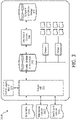
- Figure 2 depicts a System of information flow (200A) for data acquisition purposes, as used in Data Platform Module 180 of System 100A.
- This system provides a standardization around a finite number of mechanisms to reliably ingest/acquire data from either the internally accessible lighting infrastructure or other external sources. Examples of external sources of data are data from social networks such as Twitter ® and Facebook ® , weather data, security data, and scheduling data such as meeting room schedules.
- System 200A is essentially the internal plumbing that enables data flows to be connected with downstream consumption in both batch and real or near-real time. Real or near-real time data will enable low-latency real-time application experiences.
- Data acquisition in the context of the systems, methods, and apparatus for cloud-based monitoring and control of physical environments as described herein is focused on providing mechanisms or data acquisition services 220A-E to facilitate the scalable and reliable ingestion of data from diverse sources.
- These mechanisms are HTTP(S) Micro Batch Ingestion (220A), Streaming Data Ingestion (220B), Bulk Data Ingestion (220C), Social Connector (220D) and Web Content Harvestor (220E).
- a library (e.g. SDK) may be used by clients to enable simplified interaction with both the HTTP(S) (220A) and Streaming (220B) interfaces.
- HTTP(S) Micro Batch Ingestion (220A) is an application programming interface (API) that may provide, for example, standard internet facing HTTPS-based data for ingestion into the Data Fabric 230. It may use standard HTTP semantics, and is typically designed for small payloads with high horizontal scalability requirements.
- the HTTP(S) Micro Batch Ingestion API 220A may be designed to accommodate tens of thousands of requests per second. This API may typically be viewed as a Device - to - Server API.
- An example of Streaming Data Ingestion (220B) is a service or API that is designed for data acquisition over a persistent or long lived data network connection. This type of data ingestion is typically Server - to - Server.
- An example of Bulk Data Ingestion (220C) is typically an SFTP standards compliant interface for large binary object ingestion. Examples of large binary objects include large zip files and long video clips.
- An example of Social Connector (220D) is an API designed to allow services such as Social Network Data Services 210C to access the Data Fabric 230. It primarily allows for the real time ingestion of data from social networks such as Twitter ® and Facebook ® . Based on predetermined criteria, particular types of data of interest from social networks are allowed to be ingested using the 220D API.
- This information may be, for example, demographic or user profile information, or location information.
- Web Content Harvestor (220E) is a service or API for extracting content from internet websites for analytic purposes. For example, typical energy usage in buildings in a particular area may be used to benchmark energy usage in a nearby building being monitored by a system such as System 100A.
- Devices and Clients 200 represents software, firmware and hardware agents.
- data may be delivered directly or acquired via a business app/service acting as a gateway or proxy.
- Data from some sources may be routed through Clouds/Servers such as the Cloud-based Apps/Services 210A (e.g. server/app logs) for ingestion into System 200A.
- the proxy approach of the Cloud-based Apps/Services 210A does not, however, preclude the service from consuming data itself and performing some integral action (e.g. updating a database as a result of an HTTP transaction).
- the underlying message characteristics derived from the client also reaches the Data Acquisition System 200A to enable downstream analysis and/or consumption.
- FTP Server 210B
- Social Network Data Service 210C
- Internet Web Service 210D
- FTP Server 210B includes any server that uses the FTP network protocol or any derivative or extension thereof (e.g. FTPS, SSH, TFTP or SFTP) to transfer files between a client and server.
- FTP network protocol e.g. FTPS, SSH, TFTP or SFTP
- Examples of a Social Network Data Service 210C includes data services provided by social networks like Twitter ® or Facebook ® .
- Examples of Internet Web Service 210D includes any service offered by an electronic device to another electronic device communicating via the World Wide Web (WW).
- WWW World Wide Web
- Internet Web Service 210D may use the HTTP protocol for transferring machine readable file formats such as XML.
- Internet Web Service 210D is any web service that provides a web-based interface to one or more database servers in order to provide content and/or a user interface to an end user.
- the Data Fabric 230 is a data pipe that lies between the data producer and the data consumer. It comprises a data broker that enables data producers to be decoupled from data consumers, and a routing component that can control access as well as ensure that the appropriate data sets are delivered to the appropriate data consumers.
- the routing component comprises a horizontally scalable, highly available, highly durable persistent queue that supports multiple concurrent producers and consumers. It provides an API/interface for inbound message acceptance, as well as an API/interface for internal consumption.
- the Data Fabric 230 is data-driven in that it can configure a new data set and associate data sinks as appropriate with new data sets. Accordingly, there should typically be no need to re-deploy data fabric subsystems to manage the configuration of data flow within the data fabric itself.
- the routing component is also responsible for figuring out whether and where to send each message (e.g. to which data sink). In effect, it not only routes but also multiplexes (e.g. it is capable of sending the same message to multiple destinations as appropriate).
- the data sinks may be standard off the shelf data sinks. For example, a data sink may be one that is used to write (collated) messages (sets) to S3 storage. A data sink may also be one that enables near real-time consumption of messages by downstream application processing. As a general principle, all data (irrespective of source) is routed via the Data Fabric. For small data (KBs), data is delivered 'inline' within data fabric messages. For larger data sets, the data is serialized to external storage and a "pointer" is provided via a data fabric message. This approach may be used to enable near-real-time processing of larger data sets (e.g. binary content such as audio, images and video).
- Occupancy sensors determine that an office has become unoccupied and as a result, luminaires lower the light level to a predetermined level.
- Energy usage metrics collected over a contiguous period of time during which the office was in use is time stamped and sent to an appropriate wireless gateway (e.g. Gateway 110A of Figure 1 ) through, for example, the ZigBee ® communication protocol.
- the wireless gateway thereafter, after acquiring similar metrics data from other offices on the same floor of the building, communicates this information, via the HTTPS protocol to the Building Server (e.g. Building Server 100 of Figure 1 ).
- the Building Server uses the HTTPS protocol to communicate the metric data to a cloud-based application 210A.
- Cloud-based application service 210A may be required to authenticate the Building Server sending the data to it, and thereafter, depending on the type of data presented to itself, invoke the appropriate function calls to either the HTTPS Micro-Batch Ingestion 220A API or Streaming Data Ingestion API 220B. Thereafter, the data is further processed and cataloged by the Data Fabric 230, and stored in a cloud-accessible database such as the Data database 170B depicted in Figure 1 .
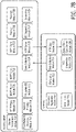
- FIG 3 illustrates an embodiment of the master data storage utilized by the Data Platform Module 180 of Figure 1 .
- all data ingested into the Data Platform Module 180 may be persisted to the Data Platform's primary storage, effectively an orchestrated tier on top of a cloud storage service such as Amazon Web Services (AWS) Simple Storage Service (S3).
- AWS Amazon Web Services
- S3 Simple Storage Service
- Many embodiments of the Data Platform Module 180 may rely on such cloud storage services for availability and durability.
- the platform introduces data organizational constructs to segregate and organize data into different cloud storage locations according to the type of data being ingested into the platform.
- FIG 3 illustrates how data from various sources (e.g. Data Fabric 310A, Data Access Services 310B, and Data Support Services 310C) are handled by the Master Data Storage and related Services that is an integral part of the Data Platform Module 160.
- Data Fabric 310A is any type of Data Fabric 230 described in the context of Figure 2 .
- Data Support Services 310B is infrastructure that controls access to data stored in Storage 340. Its main purpose is to provide access control or authentication services in order to determine if the party invoking calls to the Storage API 330 has the necessary privileges/clearance.
- Storage API 330 is able to receive the diversity of data from Data Fabric 310A when the Data Fabric 310A invokes its functional interfaces.
- the Audit & Logging Module 320 is primarily responsible for recording or logging calls to Storage API 330. Details about the party initiating the call to the API as well as results of the Data Access Services 310B authenticating said party are also recorded by Module 320. Reads from and writes to the Durable Storage Module 340 may also be recorded by Logging Module 320.
- Data Archival Services 350 represents a software or firmware module that contains and/or implements policies or rules that govern when data can be archived (e.g. sent to Long-term High Latency Storage 360) or deleted, and mechanisms to archive or restore data (e.g. from long term storage such as Storage 360).
- Data Archival Services 350 implements a pre-determined life cycle policy for data that is ingested by the Data Fabric and then stored in the Durable Storage 340.
- Durable Storage 340 is typically used for organizing and storing a diverse variety of data from a variety of sources (e.g. Hue ® data from a home) without intermingling the data.
- Durable Storage 340 implements methodologies for separately maintaining the data itself, as well as meta-data associated with the data.
- a top level of a data hierarchy may separate large scale office park project data from data coming for the homes of individuals.
- a second level of data hierarchy may be implemented by separating data based on customer identity or geo-locality.
- Dataset 1 and Dataset 2 in Figure 3 represent different data sets that are not intermingled and maintained separately for easy accessibility by Durable Storage 340.
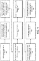
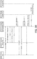
- FIG 4 illustrates an embodiment of a method for commissioning devices for use within a system for cloud-based monitoring and control of a physical environment such as system 100A of Figure 1 .
- an Installer such as the Installer described with respect to system 100A selects a system device (e.g. a luminaire) on a floor plan on a cloud-based commissioning application such as System Intake Application Module 130 described in relation to system 100A of Figure 1 .
- the Installer is at this time inside, for example, a building that is to be monitored by a system 100A.
- the Application Module 130's user interface may be displayed, for example, on a mobile device such as a smart phone or tablet used by the Installer.
- the commissioning application running on the Installer's mobile device sends the location of the selected system device on the floor plan to a cloud-based commissioning application (e.g. the back-end of the cloud-based System Intake Application Module 130).
- the cloud-based commissioning application saves the floorplan location (e.g. in the projects 170A database associated with a project hierarchy that is linked to the building that the Installer is presently in), and instructs the building server (e.g. Building Server 100 of System 100A) associated with the building in the project hierarchy to open a network connection to the correct gateway associated with the building server. In such situations, the building server is able to identify the correct gateway (e.g.
- Gateway 110A or 110B of System 100A based on the physical location of the selected system device on the floorplan of the building.
- the building server sends an open network request to the appropriate gateway.
- the gateway responds by opening its network (e.g. a ZigBee ® network).
- the Installer uses an IR remote control device to "add" the system device to the gateway's network. The Installer may do this by pointing the IR remote to the device in question, and then pressing the "Add" button on the IR remote control device.
- logic in the system device broadcasts to the gateway's open network that the system device (e.g.
- the gateway both locally adds identification information from the system device to its group of associated system devices, and sends the system device's identification information to the building server (step 470).
- the building server sends (e.g. via the MQTT or HTTPs protocol) via, for example, the Cloud Connectivity Service Module 190 and/or the Data Platform Module 180, the system device's identification information to the cloud (e.g. Cloud 115).
- a cloud-based application such as System Intake Application Module 130 couples the system device's identification information with the location on the floorplan originally indicated by the Installer in step 410, and sends the associated application running on the Installer's mobile device a confirmation message.
- the confirmation message may indicate, for example, that the system device has been successfully commissioned.
- an Installer may localize Building Server 100 and Gateway 110A and 110B. This localization may be accomplished using QR codes.
- Other System devices such as luminaires and wall switches, on the other hand, may be localized by using IR technology or button presses, as described in the use cases below.
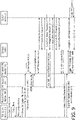
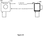
- FIG. 5A depicts a localization use case for a System device (e.g. a Sensic device such as a ceiling-mounted luminaire).
- a user e.g. Installer
- the cloud-based Application Module opens the a wireless network (e.g. a ZigBee network) of a wireless gateway (e.g . Gateway 110A) associated with the System device (Step 520A).
- the user then sends an infrared (IR) trigger to the System device using, for example, a remote control device (Step 530A).
- IR infrared
- the System device then visually indicates to the user that the IR trigger was received (e.g. by blinking a predetermined number of times) (Step 540A).
- the System device joins the wireless network and sends a SignOn message to the cloud-based Application Module (Step 550A).
- the cloud-based Application Module receives the SignOn message, changes the depiction of the icon on the user interface visible to the user to indicate successful localization (Step 560A).
- the cloud-based Application Module also sends request to the System device to visually or otherwise indicate successful localization (Step 570A). For example, if the System device is a luminaire, it might request that the luminaire dim light output to 10%. Upon receiving the request, the System device complies to indicate successful localization (Step 580A).
- the System device is now considered to be localized.
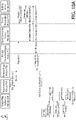
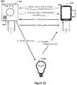
- deployment is automatically started.
- its corresponding icon on the cloud-based Application Module will change once again to indicate its "deployed” state in order to provide feedback to the user.
- a second IR trigger is received by the System device.
- the System device will send a second SignOn message to its associated wireless gateway.
- the cloud-based Application Module will, in many embodiments, receive the second SignOn message, recognize that the SignOn message is from an already localized or localization-pending System device, and choose to simply ignore the second SignOn message ( e.g. it is assumed to be an error).
- a System device is already localized to a location A (e.g. depicted on System Map Application Module 160 with particular icon), but the user nevertheless wishes to localize it to another location B (Step 510B).
- the user may indicate this by tapping another icon representing location B in the UI presented by Application Module 160.
- the cloud-based Application Module opens the w wireless network (e.g. ZigBee network) of an associated wireless Gateway (e.g. Gateway 110A) (Step 520B).
- the user then sends an infrared trigger with a remote control device to the System device (Step 530B), and the System device responds by visually indicating to the user that the IR trigger was received (e.g by blinks a predetermined number of times) (Step 540B).
- the System device may have already joined it's associated wireless Gateway's wireless network when previously localized to location A, the System device still sends a SignOn message to the cloud-based Application Module, indicating a new location corresponding to itself (location B) (Step 550B).
- the cloud-based Application Module receives the SignOn message with the System device's location information corresponding to Location B, even though the System device has already been mapped to a location corresponding to Location A.
- the cloud-based Application Module Upon receipt of the SignOn message, the cloud-based Application Module will, in various embodiments, prompt the user that the System device has previously been localized, and inquire if he/she wishes to re-localize (e.g. move) the System device to a new location (e.g. Location B) (Step 560B). If the user indicates that he/she does in fact wish to move the System device, then the System device will be localized to Location B and a new deployment of the System device will commence once any previously commenced deployment of the System device has completed (Step 570B). When the deployment of the System device is completed, an icon associated with the System device on the cloud-based Application Module will change to indicate the System device's new deployed state to the user.
- a new location e.g. Location B
- Sensic A and B there are two System devices (Sensic A and B) that are located proximally to each other.
- each may be a ceiling mounted luminaire.
- Sensic B is already localized to a Location B on the cloud-based Application Module (e.g. System Map Application Module 160).
- the wireless network e.g. ZigBee ® network
- the user sends an infrared (IR) trigger using a remote control device to Sensic A, which has not yet been localized.
- Sensic A indicates receiving the IR trigger (e.g. by blinks 3 times).
- Sensic A also joins the wireless network and sends a SignOn message, which is received by the cloud-based Application Module.
- the cloud-based Application Module has received a SignOn message from a Sensic (Sensic A), but no associated Location for Sensic A to be localized to.
- the cloud-based Application Module may enter a "Blinking Flow" sequence. In such a sequence, a list of non-localized Sensics may be presented.
- the first and only sensic in the present scenario (Sensic A) will receive a "Blink" message from the cloud-based Application Module.
- the user will need to indicate, on the UI of the Application Module, the icon (and therefore the location) that corresponds to the blinking Sensic A.
- the Application Module will proceed to localize Sensic A to the indicated location.
- Figure 5C depicts a scenario or use case where multiple System devices (e.g. Sensics) are triggered when no Location/Icon is selected on a cloud-based Application Module (e.g. System Map Application Module 160) used for localization.
- This use case may also be used to determine the sequence of events when multiple System devices are triggered with an unlocalized Icon/Location being selected on the Application Module.
- Step 510C without selecting a Location on a cloud-based Application Module, a user (e.g. Installer) sends an IR trigger using a remote control device to two or more System devices (e.g. Sensics).
- the two or more System devices visually or otherwise indicate that they have received the IR trigger (e.g. by blinking their lights 3 times each).
- the two or more System devices join an open wireless network associated with their Gateway device, and each System device sends a message indicative of a Sign On via the wireless network (e.g. a SignOn message) (Step 530C).
- the cloud-based Application Module receives the two or more indications of Sign On, and identifies, based for example on identifying information in their Sign On messages, corresponding System devices on the UI of the Application module (Step 540C).
- the identified corresponding System devices are virtual representations of the physical System devices that were triggered.
- a first System device of the two or more triggered System devices will visually or otherwise identify itself to the user (e.g. by continuing to blink). This may be due to the cloud-based Application Module sending a first of the identified corresponding System devices a request to begin blinking.
- the user will indicate on UI of the Application Module, which Location/Icon to associate with the blinking (or otherwise attention seeking) physical System device (Step 560C).
- Step 570C the cloud-based Application Module will proceed to localize the first System device to the user's chosen Location/Icon. Once successfully localized, the System device will also be deployed.
- the cloud-based application module in conjunction with the triggered two or more System devices, will cycle through each of the System devices identified by the cloud-based Application Module as corresponding to the triggered two or more System devices, in the way depicted above, so that the user has had a chance to localize each of the triggered system devices.
- a user e.g. Installer
- a Location/Icon e.g. Icon A
- the cloud-based Application Module e.g. System Map Application Module 160.
- a wireless network e.g. ZigBee ® network
- a Gateway e.g. Gateway 110A
- a few System devices e.g. Sensics A and B
- the user uses a remote control device to send an infrared (IR) trigger to both Sensics A and B.
- IR infrared
- Sensics A and B visually or otherwise indicates that the IR message was received (e.g. by blinking 3 times).
- Sensic A the Appendix
- Sensic B the Appendix
- a user e.g. Installer
- Icon A icon
- a cloud-based Application Module e.g. System Map Application Module 160
- a wireless network associated with a Gateway e.g. Gateway 110A
- the user sends an IR trigger from a remote control device to a System device (Sensic B).
- Sensic B indicates receipt of the IR message, by, for example, blinking three times.
- Sensic B may be unable to join the wireless network for a variety of reasons. For example, it may be out of range or otherwise defective. As a result, Sensic B does not send a SignOn message and does not provide the user with any visual or other indication of successful localization. Without the indication of successful indication, the user will likely realize that something went wrong in the localization process. To troubleshoot, the user can check the UI of the cloud-based Application Module to determine whether or not the Gateway associated with Sensic B or the Building Server itself is offline. Alternatively, the user may try to trigger a different as yet unlocalized System device (e.g. Sensic A) to see if the same behavior is found to occur. The user may also send a factory reset command to Sensic B using the remote control device, and thereafter try to trigger it again. Lastly, the user may replace Sensic B.
- Sensic A an unlocalized System device
- Sensic B joins the open wireless network, and then attempts to send a sign on indication (e.g. SignOn message) to the cloud-based Application Module.
- a sign on indication e.g. SignOn message
- the communication links between the cloud-based Application Module and the Gateway is subsequently broken (e.g. one or more of the communication links between the Gateway and the Building Server (e.g. Building Server 100), the Building Server and the Cloud (e.g. Cloud 115), or the cloud-based Application Module and the Cloud is interrupted)
- localization will not be able to proceed as usual. But these breaks in connectivity will be visibly indicated on the UI of the cloud-based Application Module to the user.
- the SignOn from the Sensic B will not reach the cloud-based Application Module, localization of Sensic B will not proceed.
- Sensic B will blink a predetermined number of times (e.g. three) to indicate receipt of the IR message. However, this time, if the connection issues being experienced before are resolved, the cloud-based Application Module will receive the new SignOn message sent from Sensic B, and localization will continue in the manner indicated in the previous sections. Deployment will also take place following successful localization as previously indicated.
- Sensic A a previous incorrect localization of a System device
- This discussion is for illustrative purposes only, and is not meant to be limiting.
- Sensic A has already been localized to a location associated with Icon A, which is an incorrect localization.
- Sensic C will reset, leave the network it was previously assigned to, and send a message indicating the same (e.g. a 'LeaveNetwork' message) to the Gateway associated with it.
- This sequence of events will have the effect of removing the localization of Sensic C to Icon A.
- the cloud-based Application Module e.g. System Map Application Module 160
- the appearance of Icon A will accordingly change to indicate that is not currently associated with a System device. Now, the user can proceed to localize Sensic A to the location associated with Icon B (or any other icon of his/her choice).
- the user knows that the localization of Sensic A to Icon A did not progress as expected (e.g. something went wrong during the localization process).
- the user can use the cloud-based Application Module to initiate the re-localization process.
- the user may, for example, tap Icon A in order to unmap it from Sensic A. This will remove the localization of Sensic A to the location associated with Icon A.
- the cloud-based Application Module e.g. System Map Application Module 160
- the user can localize Sensic A to the location associated with Icon B (or any other icon of his/her choice).
- Figure 6 illustrates an embodiment of the interaction of the various cloud-based system application modules that may be utilized by an exemplary cloud-based system for monitoring and control of physical environments. Some of these cloud-based applications have previously been discussed in the context of Figure 1 . Figure 6 provides additional modules and further details regarding previously discussed modules, such as their interactions with each other and their exemplary use. Users A, B, C, and D depicted in Figure 6 are users who are each associated with a different role. Based on a user's role, he or she may be granted access to one or more of the application modules.
- User A represents operational personnel, typically associated with the entity (e.g. Company Z) that hosts and or otherwise manages the operation of the exemplary cloud-based system for monitoring and controlling physical environments itself.
- User A has access to all project data (e.g. project hierarchies) maintained and controlled by the cloud-based system. It supports all other users, particularly User D, in maintaining the day-to-day operations of the end user in monitoring and controlling the various sites monitored by the cloud-based system.
- User B represents an Intake Engineer whose main function within this context may be to create a digital model of one or more buildings within a project hierarchy.
- User C is a person, such as an installer or commissioning engineer, whose main task may be to physically and logically install devices within a building based on a created digital model of a building, and thereafter participate in the commissioning, configuration and deployment processes.
- User D is personnel from a department such as facilities management, finance, or sustainability for the entity/customer (e.g. Company X) who is the end user of the exemplary cloud-based.
- the User Management Application Module 150 is a cloud-based software module that, in various embodiments, allows a system administrator, or someone similarly credentialed, to create new user accounts for the cloud-based system for monitoring and controlling physical environments.
- the system administrator may create a new user (e.g. User L) and assign that user credentials such as a username and a temporary password so that User L can thereafter use the System Login Application Module 610 to gain access to one or more of the cloud-based system application modules depicted in Figure 6 .
- the System Users Application Module 630 is used, in various embodiments, to assign users to one or more project hierarchies, sites or buildings.
- the Project hierarchy is the root of a hierarchy.
- Each Project hierarchy may contain one or more Sites, each Site may contain one or more Buildings, each Building may contain one or more Floors.
- a User e.g. User L
- a user's access rights may also be restricted in a customized fashion. For example, if User L is assigned to Site 1, he/she may be allowed access to only the buildings associated with Site 1, and not other sites within the project hierarchy to which Site 1 belongs.
- the System Project Application Module 140 is central system application module that controls access to all other system application modules.
- the application module encountered by the user is the System Project Application Module 140.
- the user will only be able to view and/or manipulate the project hierarchy, sites or buildings to which he or she has been assigned.
- the user's assignment to various project hierarchies, sites and/or buildings is associated with his or her login credentials (e.g. user ID), but his/her ability to access one or more system application modules such as System Map Application Module 160 or System Intake Application Module 130, are associated with his/her assigned role (e.g. Installer or Intake Engineer).
- the System Project Application Module 140 Once a user has accessed the System Project Application Module 140 and is presented with, for example, one project hierarchy that he/she has been assigned to (e.g. MegaCorp), he can select the project hierarchy via user interface elements presented to him on a graphical user interface. He may then be presented with the various sites associated with project hierarchy MegaCorp (e.g. London and Shanghai). Clicking on the London site will, for example, present the user with a graphical representation (e.g. icons) of the various buildings associated with the London site (e.g. Building 1 and 2). In many embodiments, the graphical user interface of the System Project Application Module 140 presented to the user will provide the user with one or more ways to access the other system application modules to which that user has access (e.g. System Operations Application Module 620 or System Energy Application Module 120) based on the user's role and/or login credentials.
- the other system application modules e.g. System Operations Application Module 620 or System Energy Application Module 120
- the System Intake Application Module 130 was previously discussed in the context of Figure 1 . In many embodiments, it allows an appropriately credentialed user such as a user who has been assigned the role of Operational personnel or an Intake Engineer to create a digital model of a building within a site and project hierarchy. In such embodiments, this also means that the user must also have the credentials to access the building through the System Project Application Module 140. Assuming the necessary credentials exist, the user (e.g. User L) will be presented with a user interface that allows him/her to add floorplans to graphically and logically represent various physical floors of a selected building.
- an appropriately credentialed user such as a user who has been assigned the role of Operational personnel or an Intake Engineer to create a digital model of a building within a site and project hierarchy. In such embodiments, this also means that the user must also have the credentials to access the building through the System Project Application Module 140. Assuming the necessary credentials exist, the user (e.g. User L) will be presented with a user interface
- a floorplan for a floor for a particular building the user can then proceed to graphically subdivide various regions within the floorplan to depict various types of spaces (e.g. cell office, open-plan office, meeting room or corridors).
- the user is graphically creating a virtual layout of the floor.
- the user is also presented with the appropriate user interface elements and functionality (e.g. drag and drop, cut-and-paste, icons representing individual devices such as luminaires and wireless gateways), so that the user can graphically depict system devices such as gateways, luminaires, grids of luminaires, switches, light and occupancy sensors, at particular locations within the many rooms or areas on a floorplan.
- configuration data which directs the behavior of devices such as luminaires within a space (e.g. how luminaires in a particular corridor respond to a change in occupancy), are also associated with the different areas (e.g. offices, corridors, open spaces) at this stage.
- System Intake Application Module 130 may also be used to associate additional configuration data to further control the behavior (e.g. light output) of individual devices such as luminaires and sensors.
- the Application Module 130 is only accessible to those users with the assigned role of Operations personnel or Intake Engineer.
- the System Map Application Module 160 is typically used by a user such as an Installer while on-site at a building that is part of a project hierarchy associated with the cloud-based monitoring and control system.
- the Installer enters the building and physically installs the devices at the locations indicated on a graphical depiction of the digital model of the building, created using, for example, the System Intake Application Module 130.
- the System Map Application Module 160 thereafter aids in the commissioning, localization and deployment processes described previously in the context of Figures 4 and 5 , and also in the context of Figures 10 , 11 and 12 .
- the Installer uses Application Module 160 to identify the appropriate digital floorplan, which provides a visualization of all of the system devices are areas on the floorplan.
- the commissioning process begins with the building server (e.g. Building Server 100) associated with the building at hand and then continues to the various wireless gateways and the associated system devices such as luminaires and switches.
- the Installer using a mobile computing device such as a smart phone or tablet, selects the particular physical device that he/she wishes to commission and localize, by selecting it on the Application Module 160's user interface.
- the Installer then proceeds to take a picture of the QR (Quick Response ® ) code on the device using a camera on the smart phone or tablet, and this initiates the commissioning, localization and deployment process discussed in detail in connection with various other figures and throughout the Specification.
- QR Quick Response ®
- the QR code is used purely as an example, and any other code may be used as well.
- System Map Application Module 160 is only accessible to those users with the role of Operations personnel or Installer.
- the System Energy Application Module 120 may be accessed by the end user, typically operations personnel associated with the entity (e.g. Company Z) that hosts and or otherwise manages operation of the cloud-based monitoring and control system, or a facilities management personnel associated with the end user entity associated with a particular project hierarchy whose buildings are being monitored by the cloud-based monitoring system. Accordingly, in various embodiments, only users with the appropriate roles (e.g. operations personnel or facilities managers) and with appropriate access credentials are allowed access to Application Module 120. In such and other embodiments, space and resource utilization data from all monitored system devices and areas are transported via their respective gateways and the building servers to the cloud associated with the cloud-based monitoring system (e.g. Cloud 115 depicted in Figure 1 ), where the data is analyzed.
- entity e.g. Company Z
- only users with the appropriate roles e.g. operations personnel or facilities managers
- Statistical analysis and machine learning techniques may be employed to derive useful analytics which are then presented to the end user in the form of graphs and other visualization modes showing past usage, predictions of future energy consumption, and present (real time) energy utilization.
- Energy consumption data analyzed in conjunction with occupancy data may reveal physical areas and resources that are poorly utilized and therefore could contribute to strategies to lower future energy utilization.
- the System Operations Application Module 620 is, in many embodiments, typically accessible only to operations personnel (e.g. User A depicted in Figure 6 ) associated with the entity (e.g. Company Z) that hosts and or otherwise manages operation of the cloud-based monitoring system. It provides the user interface and back-end logic for remotely troubleshooting, diagnosing and addressing run-time issues such as inappropriate light levels, errors in energy and occupancy data collection or analysis, or inaccurate commissioning, localization or deployment.
- FIGS 7A-C illustrate an embodiment of a deployment of the cloud-based system for monitoring and controlling physical environments depicted in Figure 1 .
- the cloud module illustrated in Figure 7A is similar to Cloud 115 described in the context of Figure 1 .
- System Project Application Module 140, System Intake Application Module 130, System Map Application Module 160, System Operations Application Module 620, System Energy Application Module 120, Cloud Connectivity Service Module 190, Data Platform Module 180 and Projects 170A are similar to the identically-named modules depicted in Figures 1 and 6 .
- Project Service Module 708 enables the various system application modules such as System Intake Application Module 130 and System Map Application Module 160 to support multiple communication protocols such as Dynet ® and ZigBee ® . It essentially allows the system application modules to perform their functions in a protocol-independent fashion. It also facilitates communication of data between the Projects 170A database and the system application modules.
- the Envision Deployment Engine Module 711 participates in the generation of configuration files for system devices such as Sensic devices. These configuration files are applicable to individual Sensics or groups of Sensics and are used to control their behavior in response to events such as changes in ambient lighting, occupancy, time of day and the like.
- the Envision Plugin Module 709 is a plugin module that allows the Envision Deployment Engine Module 711 to communicate with the Project Service Module 708 in a seamless manner. In other words, because the plugin can communicate with both the Envision Deployment Engine Module 711 and the Project Service Module 708, the Project Service Module 708 can be implemented without any dependence on the implementation or architecture of the Envision Deployment Engine Module 711.
- the Envision Data Analytics Module 714 performs the necessary analytics on energy and resource usage information gathered from all the Sensic devices by way of the building servers and gateways, and makes the analyzed data available for presentation to the System Energy Application Module 120.
- Devices 701 depicted in Figure 7A is a database module that is configured to hold information related to all the various building servers (e.g. Building Server 100), gateways (e.g. Gateway 110A), and system devices (e.g. System Device 101) that are associated with each project hierarchy.
- building servers e.g. Building Server 100
- gateways e.g. Gateway 110A
- system devices e.g. System Device 101
- a particular building server is able to be utilized for resource and energy management purposes for a particular project or site, it will need to register itself with the cloud (e.g. Cloud 115). This registration process is described in further detail in the description accompanying Figures 8A-B .
- Information associated with registered users e.g. user names, passwords, roles
- the cloud-based system of Figure 1 are securely stored in the Users 702 database module depicted in Figure 7A .
- this information is accessed by the Identity Management Module 705 during the authentication process, when a user wishes to access, for example, one or more of the cloud-based system application modules (e.g. System Map Application Module 160).
- Standard authentication techniques may be employed by the Identity Management Module 705.
- the Forgerock OpenAM/DJ Module 706 is responsible for ensuring appropriate authorization with respect to the identities for the various devices (e.g. building servers and wireless gateways) that seek access to the cloud to perform their part in an exemplary system for monitoring and controlling physical environments.
- the Policy Agent Module 707 aides in granting authorization to users to access the various depicted system application modules.
- access policies associated with the various roles are configured/implemented via URLs. For example, assume that various aspects of the System Project Application Module 140 can be accessed each with a different URL.
- the Policy Agent Module 707 enforces preset and configurable policies with respect to the functionality that each role is able to access.
- the FW Images 700 database module of Figure 7A stores the images for updating the Building Server, Gateway and System device firmware and/or software.
- the FW/SW update process starts with a trigger from the cloud's SW Update Module 703 to the Building Server via the MQTT protocol.
- the trigger may contain the URL for retrieving the necessary update image.
- the SW Update Module 703 in the cloud will send a trigger via MQTT
- the FW Update BS Module 721 in the Building Server will recognize the trigger
- the Building Server will then use the URL in the trigger to retrieve the update image and report back to the cloud using the MQTT channel that it has finished downloading the update image.
- the SW Update Module 703 in the cloud will thereafter send an explicit trigger via MQTT, and upon receiving the trigger, the Building Server will perform tasks required to switch to the new updated image (e.g. rebooting and switching to the application of the new image).
- the process for performing a firmware update of a Wireless Gateway is similar to the above-described firmware update for the Building Server. However, the update process for the Wireless Gateway uses the Building Server as a proxy. For example, the retrieval of the FW image via a URL by the Wireless Gateway is proxied via the HTTP Proxy Module 718 depicted in the Building Server module in the present figure.
- the Building Server depicted in Figure 7A is similar to Building Server 100 described in the context of Figure 1 .
- This embodiment of the Building Server depicts various modules that play role(s) in facilitating software updates, device registration, and data collection.
- the HTTP Proxy Module 718 and the MQTT Proxy Module 720 proxy communications using the HTTP and the MQTT protocols, respectively, between one or more wireless gateways and the cloud. For example, communications arising from the MQTT client in a wireless gateway associated with the Building Server of Figure 7A is routed by the MQTT Proxy Module 720 of the Building Server.
- only one device e.g. a building server
- only one device within a physical environment that is being monitored will have direct access to the cloud that is being used to monitor the environment.
- the Device Registration Module 716 orchestrates the registration of the Building Server with the Cloud. This process is described in more detail in the description accompanying Figures 8A-B .
- the Field Network Discovery Module 717 is involved in the process of discovering devices in the network.
- the Network Provider Module 719 receives configuration data from the Envision Plugin Module 709 in the Cloud and is responsible for forwarding this data to the System devices (e.g. Sensic devices). Additionally, the Network Provider Module 719 facilitates bi-directional communication between the Cloud and the Wireless Gateway.
- the Network Provider Module 719 can also propagate commands from the Cloud (e.g. open ZigBee network commands) to the Wireless Gateway.
- the Failover Module 726 and Recovery Module 728 are together responsible for detecting and recovering from errors in the Building Server's operations.
- the operation of one or more key software processes is continually monitored by way of a timer.
- the timer also stops.
- the timer stopping is a trigger that results in the one or more processes or the Building Server itself restarting to recover from the error condition.
- the BS Diagnostics Module 727 gathers information on the routine operation of the Building Server. For example, in many embodiments, error messages that may help in diagnosing operating errors are collected. These messages are periodically sent to the Cloud for analysis and visualization by system application modules such as System Energy Application Module 120.
- the Scheduling Module 729 in the Building Server is involved in scheduling tasks that override the usual behavior in a physical environment (e.g. building) that are based on events such as changes in occupancy or daylight.
- the Scheduling Module 729 is executed in the Building Server, whereas in others, it is executed in the Cloud.
- the Gateway (e.g. a wireless gateway) depicted in Figures 7B and 7C is similar to Gateways 110A and 110B previously described in the context of Figure 1 .
- Figures 7B and 7C depict various modules of the Wireless Gateway. As with most modules described throughout this Specification, these modules may be implemented in firmware or entirely in software. If implemented entirely in software, they may be executed on one or more processor located physically at the Wireless Gateway itself or on one or more processors located remotely, but accessible to the Wireless Gateway.
- the NTP Client Module 735 of the Wireless Gateway is similar to the similarly named module in the Building Server, in that it participates in pushing time data to the System devices such as Sensics.
- the ZigBee Clock Sync Server Module 736 of the Wireless Gateway also participates in this time-synchronization-related process, and its participation, along with the Wireless Gateway's NTP Client Module 735 is described in more detail in the next section on time synchronization.
- the Data Collection Module 733 of the Wireless Gateway is involved in the collection of energy and other metrics from the System devices (e.g. Sensics) and pushing this information upward to the Cloud by way of the Building Server. Details regarding its functionality are described in the following section on metric reporting.
- the WG Diagnostics Module 734 is primarily responsible for reporting error or otherwise abnormal conditions or states encountered during the routine operation of the Wireless Gateway. These error conditions or states are thereafter reported up to the Cloud via the Building Server for further analysis and presentation.
- the FW Update Module 732 of the Wireless Gateway is primarily responsible for coordinating the firmware and software updates for itself and for Sensic devices. This process is described in further detail in the context of the Figure 9 .
- the Discovery Registration Module 730 of the Wireless Gateway functions to register itself with the Building Server and/or the Cloud.
- the MQTT Client Module 731 works to route communications based on the MQTT protocol arising from the Wireless Gateway, and any device in communication with the Wireless Gateway, to the Building Server via the Building Server's MQTT Proxy Module 720.
- the Sensics depicted in Figure 7C are similar to the devices 101-106 described in the context of Figure 1 .
- the Sensic Diagnostics Module 737 reports error states and conditions associated with the usual operation of the Sensic to the Metric Reporting module, which is described in the following section on time synchronization.
- the ZigBee Clock Sync Client Module 743 and ZigBee Clock Sync Server Module 744 are also described in the following section on time synchronization.
- the FW Update Module 742 participates in the process of updating the Sensic's firmware and/or software, and this process is discussed in more detail in the description accompanying Figure 9 .
- the Sensor 740 senses, for example, infrared signals, changes in motion or light intensity.
- the Actuator 738 actuates devices, such as luminaires, to change, for example, the intensity or other characteristics associated with illumination. It may also actuate a variety of other devices found in buildings, such as HVAC devices, blinds, curtains, projectors, displays, and the like.
- the Envision Control Module 739 functions to apply configuration data (e.g. configuration files) passed down to the Sensic from the Envision Deployment Engine Module 711 and Envision Plugin Module 709 in the Cloud via the Building Server and the Gateway.
- the configuration file details the response of the particular Sensic or a group of Sensics to various lighting and environmental conditions such as changes in occupancy, temperature or movement.
- the NTP Client Module 723 depicted as part of the Building Server in 7A is used for time synchronization purposes. It works in conjunction with an NTP Server Module 715 on a network such as the Internet, an NTP Server Module 725 that is also part of the Building Server depicted in Figure 7A , and the NTP Client Module 735 and ZigBee Clock Sync Server Module 736 depicted as part of the Wireless Gateway WG in Figure 7B .
- NTP generally refers to the known Network Time Protocol, which is a networking protocol commonly used for clock synchronization between computer systems. NTP typically works to synchronize computing devices to be within a few milliseconds of a Coordinated Universal Time (UTC). While NTP may operate under the Client-Server model, it can also be used in peer-to-peer solutions, where multiple devices may be considered a potential time source.
- UTC Coordinated Universal Time
- the current time data is first retrieved from the NTP Server Module 715 depicted as being outside of the Cloud or Building Server. Generally such an NTP Server is on the Internet.
- the Building Server's NTP Client Module 723 receives the current time data.
- this current time data is received by the NP Server Module 725 in the Building Server, before it is communicated to the NTP Client Module 735 of the Wireless Gateway depicted in Figure 7B .
- this current time data is in turn communicated to the ZigBee Clock Sync Server Module 736.
- a level discovery phase is initiated to identify those Sensic devices that are closest to the Wireless Gateway.
- this is accomplished by the Wireless Gateway sending a broadcast command via ZigBee with a particular level (e.g. a level 0 associated with itself).
- a level 0 associated with itself.
- Sensic devices closest to the Wireless Gateway receive the broadcast command, they increase their own level to 1 and then re-broadcast the same or a similar message with a level 1.
- Sensic devices receiving the re-broadcast message will thereafter identify themselves with a level 2 and re-broadcast the message again. This process continues until all neighborhood Sensic devices have been identified and are associated with a level.
- the second phase following the level discovery phase is a synchronization phase, which involves using a known pair-wise time synchronization algorithm.
- the ZigBee Clock Sync Client Module 743 of one of more Sensics at a first level receives the current time data from the ZigBee Clock Sync Server Module 736 of the Wireless Gateway. This information is then propagated peer-to-peer by the Sensics themselves. This may be a result of the ZigBee Clock Sync Server Module 744 of a particular Sensic communicating this information via the ZigBee network for reception by the ZigBee Clock Sync Client Module 743 in a neighboring Sensic, as indicated in Figure 7C with the arrow lines.
- Sensics will report energy and/or occupancy data periodically (e.g. energy data may be reported every fifteen minutes and occupancy data every fifty seconds).
- the Metric Reporting Module 741 shown in Figure 7C as part of each Sensic, receives time data from the ZigBee Clock Sync Client Module 743, which is then added as a time stamp to the reported energy or resource usage data.
- the Sensic Diagnostics Module 737 also provides the Metric Reporting Module 741 with diagnostic data regarding the operation of the Sensic itself. This diagnostic data may be error messages indicating potential or known issues with the routine operation of the Sensic, such as the inability to sense or actuate in the usual manner.
- metric data is transmitted from each Sensic in the following manner.
- a packet type for transmitting address information For example, metric related to energy usage
- the full time stamp with a first metric relating to energy usage is transmitted.
- a second metric relating to energy usage is transmitted along with time offset data indicating the amount of time that has elapsed since the transmission of the first metric.
- the metric data is received by the Data Collection Module 733 of the Wireless Gateway
- the Sensic does not itself provide any address information that uniquely identifies itself to the Wireless Gateway when reporting metric data.
- the Data Collection Module 733 in the Wireless Gateway (depicted in Figures 7B and 7C ) appends or otherwise associates a globally unique address for the Sensic to its reported metric.
- the Data Collection Module 733 in the Wireless Gateway may also add its own address information.
- this combination of the Wireless Gateway's address information and an address associated with a particular Sensic or group of Sensic is what results in the globally unique nature of the address associated with a particular metric or collection of metrics being reported.
- the Data Collection Module 733 in the Wireless Gateway receives information from the Sensics typically using the ZigBee protocol, but provides information to the Building Server typically using HTTPS.
- the Wireless Gateway's Data Collection Module 733 transmits data to the Data Collection Module 724 in the Building Server.
- the Wireless Gateway pushes this information periodically.
- the Building Server pulls this information from the Wireless Gateway.
- the Data Collection Module 724 of the Building Server adds its own address to the address information. This address information may be added to each received metric received from the Wireless Gateway, or collectively to a whole batch of metrics prior to transmitting the batch of metrics to the Cloud.
- the Building Server collects all the received metrics for a short period of time (e.g. 5 seconds) prior to batch transmitting the metrics to the Cloud's Data Platform Module 180.
- the metric data received from all the Wireless Gateways associated with the Building Server will be buffered for a maximum duration of time (e.g. 24 hours).
- the Building Server will push the buffered metric data to the Cloud.
- such buffering is also available at the Wireless Gateway to prevent data loss if connectivity between the Wireless Gateway and the Building Server is disrupted.
- FIGS 8A and 8B illustrate an embodiment of a method of registering and connecting a Building Server with a Cloud (e.g. Cloud 115 of Figure 1 ) of a cloud-based system for monitoring and controlling a physical environment.
- the boxes at the top of both figures represent a Building Server inside a facility (e.g. Building Server 100 of Figure 1 ), and various cloud-based modules associated, for example, with Cloud 115 of Figure 1 .
- Device Registration Module 704, Identity Management Module 705, Data Platform Module 180 are all embodiments of identically named cloud-based modules previously described in the context of Figure 7A .
- the Building Server 100 retrieves a locally saved MAC address that identifies the building server uniquely across of all vendors of building servers ( retrieve Building Server ID() ) . Thereafter, Building Server 100 initiates, for example, a device-to-service communication ( Register () ) by way, for example, of an API call.
- Register () a device-to-service communication
- the Device Registration Module 704 in the Cloud e.g. Cloud 115
- Building Server 100 to register itself with the Cloud, Building Server 100 communicates its retrieved Building Server ID (e.g. a 64 bit MAC address), a device type indicating that it is a Building Server, and a keyed-hash message authentication code (HMAC).
- HMAC keyed-hash message authentication code
- HMAC is a known cryptographic message authentication code that uses a hash function in combination with a secret key. It is used to verify both message authentication and data integrity.
- An HMAC may be calculated using any known cryptographic hash function, such as MD5 or SHA-1.
- the Device Registration Module 704 has access to a database that stores a secret cryptographic key for each building server. Each building server in turn has access to its own copy of the secret cryptographic key, but not the cryptographic keys of any other building server.
- the Device Registration Module 704 on the Cloud thereafter verifies that the received Building Server ID and HMAC are associated with each other ( Verify BSID and HA4AC() ) . In doing so, the Device Registration Module 704 authenticates Building Server 100. If, during this process, the Device Registration Module 704 receives multiple registration attempts from a building server that it is unable to verify/authenticate, then it may temporary block such attempts from the building server.
- the Device Registration Module 704 creates a password ( Create Password () ) that, in combination with the Building Server ID will act as the building server's operational ID when interacting with various cloud-based modules.
- the Device Registration Module 704 then invokes the Identity Management Module 705 to have it create a new identity ( Create Identity() ) that represents Building Server 100 within the cloud-based system for monitoring indoor space and resource usage.
- the Building Server ID and password are used to formulate the new identity.
- the Identity Management Module 705 proceeds to add Building Server 100 to a group of building servers recognized by the Cloud ( Add To Group() ) .
- each building server registered with the Cloud belongs to a group that may be referred to as the Building Service group. Belonging to this group is one way of identifying a device as a special type of device, namely a Building Server.
- the Identity Management Module 705 notifies the Device Registration Module 704 of successful completion ( depicted by the dotted arrow from Identity Management module 705 to Device Registration Module 704).
- the Device Registration Module 704 creates a cryptographic Certificate for the Building Server 100 to use in order to function as a secure server.
- the Certificate is a public key that is signed and encrypted using a private key of a Certificate Authority.
- the user of the Certificate e.g. Building Server 100
- the Device Registration Module 704 then sends the password it previously generated for Building Server 100, the created Certificate, the encrypted private key, and information on a resource (e.g. an MQTT endpoint or URL) that Building Server 100 can use to communicate with the Cloud, to Building Server 100 (depicted by the dotted arrow from Device Registration Module 704 to Building Server 100).
- a resource e.g. an MQTT endpoint or URL
- Building Server 100 Upon receipt of the above-identified pieces of information from the Device Registration Module 704, Building Server 100 decrypts the encrypted private key ( Extract Install Private Key Certficate() ) , using, for example, it's secret key that it already shares with the Device Registration Module 704. For secure communications within the building itself (e.g. between Building Server 100 and various wireless gateways), a shared secret may be used to ensure secure connections between these devices. Building Server 100 generates a Site Key as such a shared secret for use within the building ( Generate Install Site Key() ) .
- Building Server 100 attempts to have itself authenticated by the Identity Management Module 705, by, for example, providing its Building Server ID and the password it received from the Device Registration Module 704 ( Authenticate (BSID, Password) ) . If the authentication is successful, Identity Management Module 705 returns an access token that Building Server 100 may use to subsequently access services in the Cloud (depicted by the dotted arrow labeled 'Access Token').
- Building Server 100 is required to have a second set of access credentials. This essentially separates the security related to gaining access to all the other cloud modules from the security associated with access to the Cloud's data platform itself.
- the following discussion deals with the part of Building Server 100's registration process that will result in granting this additional set of credentials.
- the Building Server invokes, for example, an API call ( Activate Data Platform (BSID, Password) ) and provides its Building Server ID as well as its password. This communication may occur over HTTPS.
- the Device Registration Module 704 invokes the Identity Management Module 705 to verify the supplied credentials ( Verify Credentials (BSID, Password) ) .
- the Device Registration Module 704 proceeds to generate another password for Building Server 100 to use ( Create Password () ) for its communications with Data Platform Module 180.
- the Device Registration Module 704 then provides the Data Platform Module 180 with the following information: the Building Server ID, the new password for data platform access, and information on the particular group that Building Server 100 belongs to ( Subject Device Group () ). In many embodiments this communication may be accomplished via HTTPS.
- the Data Platform Module 180 creates a unique identity for use in identifying Building Server 100 in its future interactions with the building server ( Create DP Identity () ).
- the Data Platform Module 180 Upon successfully creating this new identity, the Data Platform Module 180 notifies the Device Registration Module 704 of the same ( dotted arrow from Data Platform Module 180 to Device Registration Module 704 labeled DP Identity). The Device Registration Module 704 in turn passes on this notification of success to Building Server 100 along with the newly generated data platform credentials of the building server ( dotted arrow from Device Registration Module 704 to Building Server 100 labeled DP Identity).
- Building Server 100 attempts to get itself authenticated directly with Data Platform Module 180 by invoking, for example, API for this purpose at the Data Platform Module 180. It supplies the data platform with its Building Server ID and the password created by Data Platform Module 180. In turn, Data Platform Module 180 verifies the credentials supplied by Building Server 100 ( Verify Credentials() ) and returns an access token for use by Building Server 100 in future communications with Data Platform Module 180 ( dotted arrow from Data Platform Module 180 to Building Server 100 labeled Data Platform Token).
- Building Server 100 connects to the Cloud for the first time by, for example, invoking a method of the Cloud Connectivity Service Module 190 using an API it provides, and supplying its Building Server ID and the password initially created for Building Server 100 by the Device Registration Module 704 ( Connect (BSID, Password) ) .
- the Cloud Connectivity Service Module 190 invokes an authenticate method, whereby the Identity Management Module 705 is asked to authenticate the Building Server's credentials.
- the Building Server ID and Password provided by Building Server 100 are used for this purpose ( Authenticate (BSID, Password) ) .
- the authentication process may be initiated by the Cloud Connectivity Service Module 190 at the Identity Management Module 705 using the HTTPS protocol.
- the Identity Management Module 705 Upon successful authentication, the Identity Management Module 705 returns a token to the Cloud Connectivity Service Module 190 indicating that Building Server 100 has been successfully authenticated ( depicted by dotted arrow labeled 'Token' ) . Using the received Token, the Cloud Connectivity Service Module 190 then requests that the Identity Management Module 705 retrieve the Group that Building Server 100 was previously assigned to ( retrieve Group (Token) ) . In response, the Identity Management Module 705 returns a reference to the Group that Building Server 100 is assigned to (e.g. a Group that contains references to all the registered building servers associated with the particular Cloud).
- the Cloud Connectivity Service Module 190 can verify the authorization of Building Server 100 ( Verify Authorization () ). To do this, in various embodiments, the Cloud Connectivity Service Module 190 checks to see Building Server 100 belongs to the correct authorization group. System devices like building servers and gateways are usually associated with a Devices group. As a result, when any device connects to the Cloud Connectivity Service Module 190 using MQTT, the Cloud Connectivity Service Module 190 checks to see if the device is, in fact, part of the Devices group. In many embodiments, only devices or services (e.g.
- the Envision Protocol Plugin but not users, are allowed to connect to the Cloud via MQTT.
- the Cloud Connectivity Service Module 190 sends a notification back to Building Server 100 (using, for example, MQTT) indicating that it is successfully connected ( depicted by dotted arrow from Cloud Connectivity Service Module 190 to Building Server 100 labeled 'Connected').
- Building Server 100 can thereafter publish a "Sign On” message via the Cloud Connectivity Service Module 190 using, for example, the "Publish” mechanism of MQTT.
- the "Sign On” message is published to a particular Topic associated with the particular Building Server. In MQTT, different topics are associated with different channels or functionalities.
- the Cloud Connectivity Service Module 190 pushes Building Server 100's Sign On message ( Building Server SignOn () ) to all subscribers of the Topic that Building Server 100 wishes to publish its Sign On message to.
- the Envision Plugin Module 709 receives the Sign On message and acknowledges receipt ( depicted by dotted arrow from Envision Plugin Module 709 to Cloud Connectivity Service Module 190 labeled ACK').
- the Envision Plugin Module 709 promptly reports the same to the Project Service Module 708, so that it is aware of a new device signing on, and can take any necessary actions ( Call Back Discovered Device () ).
- Figure 9 illustrates an embodiment of a method of updating the software or firmware of a System device such as a Sensic device (e.g. Device 101 of Figure 1 ).
- the arrows shown in the Figure 9 could represent function calls, commands, or any other mechanism for invoking action or response from an executing piece of software or firmware on the same or a different, but accessible processor.
- HTTPS is sometimes referred to as the communication protocol between, for example, the Building Server and the Gateway, or the Building Server and the Cloud.
- HTTPS is one of many protocols that may be used in any embodiment. For example, MQTT may also be applicable for these communications.
- SW Update Module 703, Project Service Module 708, and SW Images 700 are software modules that reside in a cloud, such as Cloud 115 of Figure 1 or the Cloud of Figure 7A .
- Project Service Module 708 depicted here is similar to the Project Service Module 708 depicted in Figure 7A .
- the remaining three modules or devices illustrated at the top of this figure, namely, FW Update BS Module 721, Gateway 110A and System Device 101 represent physical devices or modules executing on processors associated with physical devices that are located within a physical structure such as a building.
- the SW Update Module 703 first executes an "Open" command or function call on the Project Service Module 708.
- the SW Update Module 703 wishes to open a particular pre-existing project hierarchy. Project hierarchies have been previously discussed in the context of Figures 5A-C and 6 .
- a logical model of the particular project is returned, using which the SW Update Module 703 gains access to data associated with a particular floor ( Select (floor) ) and data associated with one or more system devices (e.g. sensic devices) on the particular floor ( Select (System device) ) .
- the Browse for Update File() arrow indicates that the SW Update Module 703 requests or otherwise retrieves from the SW Images 700 repository, the URL of an update file related to the system device that the SW Update Module 703 previously selected.
- the SW Update Module 703 thereafter sends to the Building Server's FW Update BS Module 721, a FW Update message ( FW Update (file URL, Device MAC, Communication path) ) with one or more of the URL of the system device's update file, a Device MAC and a communication path.
- the communication path may be empty. If a Gateway (e.g. a wireless gateway) is to be updated, the communication path is the IP address of the Gateway.
- the communication path is the IP address of a Wireless Gateway and/or a ZigBee short address.
- the FW Update (file URL, Device MAC, Communication path) arrow will bypass the FW Update BS Module 721 completely and proceed to invoke the Gateway's FW Update Module 732 directly, at least in the case of updates for system devices such as Sensic devices.
- the Building Server's FW Update BS Module 721 checks ( Check Device MAC () ) to determine if the Device MAC supplied by the SW Update Module 703 belongs to a building server (e.g. itself).
- the HTTPS GET (file URL) arrow indicates the FW Update BS Module 721 using the HTTPS protocol to retrieve the appropriate update file using the file URL previously received from the SW Update Module 703.
- the Building Server's FW Update BS Module 721 notifies ( FW Update () ) the appropriate Wireless Gateway (e.g. one associated with the Sensic device to be updated), with a file URL of the update file.
- the Device MAC and communication path may also be relayed to the Wireless Gateway at this time.
- the Wireless Gateway 110A retrieves the update file from the Building Server using the conveyed file URL ( HTTPS Get (file URL) ) .
- the Wireless Gateway itself may implement an HTTPS server, rather than having to query the Building Server for this information.
- the Wireless Gateway may also poll the Building Server for new updates periodically. Additionally, the Wireless Gateway may implement a TLS server socket.
- the Image Notify () arrow is a trigger that the Wireless Gateway sends to the particular Sensic needing an update that there is a new update available.
- the Query Next Images () arrow arising out of the Sensic (System Device 101) is a response to the trigger from the Sensic, essentially inquiring about details associated with the new update.
- the Query Next Image Response () arrow arising out of the Wireless Gateway is a response to this query. This response may contain information related to the update, such as versioning information (e.g. major and minor version numbers) and hardware IDs.
- a loop of requests and responses are performed until the whole of image associated with the Sensic's update file has been transferred to the Sensic itself.
- the loop begins with the Sensic requesting an image block from the Wireless Gateway ( Image Block Request () ) .
- the Wireless Gateway responds with the requested Image Block ( Image Block Response () ).
- the loop terminates once all the image blocks in the update image file have been received by the Sensic device.
- the Sensic device requests further instructions on proceeding from the Wireless Gateway, by, for example, invoking the Upgrade End Request () method.
- the Wireless Gateway may respond to the Sensic by indicating that it should not refrain from starting the software/firmware update until further notice ( Update End Response () ).
- Update End Response () This Upgrade End Request / Response communication is usually accomplished using the ZigBee protocol, but is not necessarily limited to it.
- the Wireless Gateway invokes a method to notify the Building Server's FW Update BS Module 721 of a new status associated with the Sensic Device ( HTTPS (Status, Device MAC) ) .
- the Building Server's FW Update BS Module 721 Upon receipt of this notice, the Building Server's FW Update BS Module 721, in turn, notifies the SW Update Module 703 on the Cloud that a Sensic device associated with a particular MAC address is ready for an Update ( Status Update (Device MAC) ) .
- the SW Update Module 703 may invoke a method at the Building Server's FW Update BS Module 721 to trigger the initiation of the update at the Sensic device ( Trigger FW Update (Device MAC, communication path) ) . This trigger may communicate the Sensic device's MAC address and/or the communication path of the Sensic device.
- the Building Server's FW Update BS Module 721 in turn notifies the Wireless Gateway of the update trigger using a similar mechanism ( Trigger FW Update ( ... ) where "" in Figure 9 refers to Device MAC, communication path ) .
- the Wireless Gateway 110A notifies the Sensic Device identified by the MAC device address and/or communication path that it may now begin applying the update ( Update End Response(Now) ) .
- the Sensic thereafter applies the update using the image blocks of the update previously received ( Apply FW Update() ) .
- the Sensic After the Sensic has finished installing the update and has performed other necessary tasks, like successfully rebooting, it indicates to the Wireless Gateway that it is now ready to sign on and resume usual operations ( Sign On() ) .
- FIGS 10A and 10B together illustrate an embodiment of a method of localizing a Building Server at the exemplary cloud-based system for monitoring and controlling physical environments.
- the boxes at the top of both figures represent a Building Server 100 inside a facility (e.g. Building Server 100 of Figure 1 ), and various cloud-based modules associated, for example, with Cloud 115 of Figure 1 .
- Project Service Module 708, Envision Plugin Module 709, Envision Deployment Engine Module 711, Cloud Connectivity Service Module 190, and Device Registration Module 704 are all embodiments of identically named cloud-based modules previously described in the context of Figure 7A .
- System Map Application Module 160 is a cloud-based application module previously described in the context of Figures 1 and 6 .
- User C depicted on the left of Figure 10A was also previously described in the context of Figure 6 .
- User C is a person, such as an installer or commissioning engineer, whose main task may be to physically and logically install devices within a building based on a created digital model of a building.
- User C or some other similarly credentialed user can thereafter participate in the commissioning, configuration and deployment processes.
- the presently depicted embodiment begins with the Project Service Module 708 in the Cloud self-starting ( Start Project Service () ), and invoking an instance of the Envision Plugin Module 709 ( Start () ) .
- the instance of the Envision Plugin Module 709 registers itself with the Cloud Connectivity Service Module 190 ( Register () ) .
- the Building Server 100 in a building to be monitored registers itself with the Device Registration Module 704.
- the Building Server 100's registration process has been described in more detail in the description accompanying figures 8A and 8B .
- One of the initial steps in the registration process involves the Building Server 100 invoking an API call ( Register () ) at the Device Registration Module 704, and providing its locally stored Building Server ID, which is, in various embodiments, a MAC address.
- the Device Registration Module 704 upon successful registration, returns an address/location at which the Building Server 100 can continue further communications with the Cloud, and the credentials that the Building Server 100 is required to present to access various services offered by the Cloud ( Connection Settings() ) . These credentials are typically issued per Building Server instance.
- the Building Server 100 next initiates the creation of a secure connection by contacting the Cloud Connectivity Service Module 190 at the address/location provided by the Device Registration Module 704 ( Create Connection (Building Server ID) ).
- the Cloud Connectivity Service Module 190 Upon successful setup of a secured connection with the Cloud, the Cloud Connectivity Service Module 190 notifies the Building Server 100 of the same ( depicted by the arrow labeled 'OK' ).
- Building Server 100 proceeds to announce itself to the Cloud - via the Envision Deployment Engine (EDE) Module 711. It essentially invokes API exposed by the EDE Module 711 for this very purpose, and provides various pieces of information about itself (e.g. it's Building Server ID, and software and hardware versioning information). This is represented by the arrow labeled Building Server Announce (Device Information) in Figure 10A .
- the Project Service Module 708 which is the module that communicates data from devices such as Building Server 100 System Application Modules such as System Project Application Module 140 and System Map Application Module 160, the Building Server's announcement has to first be propagated to the Envision Plugin Module 709 ( Building Service Announce() ) .
- the Building Server Announcement from Building Server 100 is sent directly to the Envision Plugin Module 709 itself, rather than to the Envision Deployment Engine Module 711.
- the Project Service Module 708 is notified, and it adds the Building Server to a list of known devices (A dd Device to Discovery List () ) .
- Project Service Module 708 may do so by any known means, such as adding the Building Server's ID as well as other information (e.g. versioning information) to a database.
- a user may access a system application module (Star App ) while he/she is onsite using the front-end of the application presented on a mobile device such as a tablet computer.
- User C may be, for example, an Installer or Commissioning Engineer who has previously been granted the necessary access credentials to access one or more system applications, such as System Map Application Module 160.
- Exemplary system application modules were previously discussed in more detail in the context of Figures 1 and 6 .
- System Map Application Module 160 then fetches or requests ( Get () ) from Project Service Module 708, a previously created data model for the selected Building.
- Project Service Module 708 provides a digital Floor Plan associated with the selected Building ( Floor Plan () ), which is thereafter displayed on the front-end of the System Map Application Module 160 executing on User C's mobile computing device ( dotted arrow).
- User C indicates on the front-end of the System Map Application Module 160 that he/she wishes to localize a Building Server ( Selection (Building Server) ). This may be done by simply selecting an icon of a building server, and dragging it onto a visual representation of the building's floor plan.
- This user interaction with system application module indicates that it is time for User C to take a picture of the Building Server's unique, manufacturer provided QR code.
- the Application Module 160 activates the Camera device on User C's mobile computing device ( Start Camera () ), and requests the QR code from User C ( Ask For QR Code() ) .
- User C complies by taking a picture of the portion of the Building Server that contains the QR code.
- the QR code is used as an example here and is not meant to be limiting. Any unique code physically mounted or otherwise affixed on the Building Server may be used in other embodiments.
- the System Map Application Module 160 thereafter extracts the QR code from the image captured by the camera device on User C's mobile device ( Return QR Code (ID)
- the Project Service Module 708 associates, in a memory, the physical device (e.g. Building Server whose QR code was captured in an image by User C) with a virtual device for localization onto the floor plan of the model of the Building in which the physical Building Server resides ( Associate Physical To Virtual Device (Model, Discovered Device Profile) ).
- the Project Service Module 708 thereafter returns an acknowledgement ( dotted arrow ) to the System Map Application Module 160.
- Application Module 160 checks to determine whether or not the Building Server that User C is localizing is online or offline. Accordingly, it invokes the appropriate API call at the Project Service Module 708, and provides the requisite Building Server ID ( Get Online Status (Building Server ID) ). The Project Service Module 708 performs a lookup (e.g. in a database) using the supplied Building Server ID to retrieve the associated Discovered Device Profile ( Lookup (Building Server ID, Discovered Device Profile) ).
- the Project Service Module 708 then invokes the Envision Plugin Module 709 with the appropriate ID of the Building Server and a request for online status ( Get Online Status (BS ID) ), which the Envision Plugin Module 709 can thereafter use to contact the correct Building Server to directly request online status information ( Request Online Status() ) .
- Building Server 100 then returns its online status (e.g. an indication of whether it is presently online or offline) ( dotted arrow ).
- This information is then propagated by the Envision Plugin Module 709 to the Project Service Module 708 via, for example, an invocation of the appropriate API call ( Call Back Device Status (Online) ). Based on the information received by the Project Service Module 708 (e.g.
- the Project Service Module 708 informs the System Map Application Module 160 appropriately ( alternate dotted arrows Online and Offline ). If Building Server 100 is presently online (e.g. at the time User C is attempting to complete the localization process), then System Map Application Module 160 informs User C that the Building Server has been successfully localized ( Show Successful Localization () ) . Alternatively, if Building Server 100 is presently determined to be offline, then the Project Service Module 708, in various embodiments, removes the previously created association between the Discovered Device Profile and the physical Building Server, and the System Map Application Module 160 informs User C that the Localization has failed ( Show Localization Failure () ) . User C may be informed of the reason that the localization failed, for example, that Building Server 100 is offline and it is necessary for the Building Server to be online for localization to complete appropriately.
- Figure 11 illustrates an embodiment of a method of localizing a wireless Gateway (e.g. Gateway 110A of Figure 1 ) at the exemplary cloud-based system for monitoring and controlling a physical environment.
- the boxes at the top of the figure represent a Building Server 100 inside a facility (e.g. similar to Building Server 100 of Figure 1 ), and various cloud-based modules associated, for example, with Cloud 115 of Figure 1 .
- Envision Plugin Module 709, and Project Service Module 708 are embodiments of identically named cloud-based modules previously described in the context of Figure 7A .
- System Map Application Module 160 is a cloud-based application previously described in the context of Figures 1 and 6 .
- User C depicted on the left of Figure 11 was also previously described in the context of Figure 6 .
- User C is a person, such as an installer or commissioning engineer, who performs tasks such as physically and logically installing devices within a building based on a created digital model of a building, and thereafter participating in the commissioning, configuration, and/or deployment processes.
- the localization process for wireless Gateway 110A begins with the wireless Gateway sending a Sign On message via, for example, the MQTT protocol.
- the Sign On message in many embodiments, contains the Building Server's unique ID, the IP Address of the wireless Gateway, information regarding the gateway, and an ID associated with the wireless Gateway ( Sign On (Building Server ID, IP Address, Device Info, Wireless Gateway ID) ).
- the Building Server runs an MQTT proxy (e.g. as depicted in Figure 7B ), which then forwards the Sign On message to the Envision Plugin Module 709 (depicted as second arrow labeled Sign On (Building Server ID, IP Address, Device Info, Wireless Gateway ID)).
- the Envision Plugin Module 709 forwards the Sign On message and its associated parameters to the Project Service Module 708 running on Cloud 115. To do so, it may invoke a CallBack method or function that the Project Service Module 708 exposes as part of its API ( CallBack (Building Server ID, IP Address, Device Info, Wireless Gateway ID) ).
- CallBack is a way of informing the Project Service Module 708 that a new device, yet to be localized, is attempting a sign on and is available.
- the Project Service Module 708 then adds the information regarding the wireless Gateway 110A received in the Call Back to its list of "new" devices it did't encountered previously ( Add Device To Discovery List () ) .
- User C graphically selects an icon representing wireless Gateway 110A on the user interface of the System Map Application Module 160 executing on a portable computing device such as a tablet computer ( Selection of Wireless Gateway ).
- This causes the System Map Application Module 160 to activate a camera application on the portable device ( Start Camera () ) .
- the Map Application Module 160 may then prompt User C for a QR Code associated with the wireless Gateway ( Ask For QR Code () ) .
- Ask For QR Code () a QR Code associated with the wireless Gateway
- User C points the camera to a part of the wireless Gateway that has the QR Code on it, and takes a picture ( Take Picture () ) .
- the image is then analyzed by the Map Application Module 160 and the QR Code is extracted ( Return And Decode QR Code () ).
- the Map Application Module 160 requests that the Project Service Module 708 associate the physical device associated with the QR Code with the Virtual Device represented in the Building's data model (e.g. on the digital floor plan of the Building) and represented on the Map Application Module 160's graphical user interface ( Associate Physical To Virtual Device (QR Code, Virtual Device ID) ).
- the Map Application Module 160 supplies the QR Code and in order to identify the virtual device, it supplies a virtual device ID.
- the Project Service Module 708 locates the virtual device in its list of discovered devices ( Search For Device In List () ), and thereafter associates, in a memory, the physical device (e.g.
- the wireless Gateway whose QR Code was captured in an image by User C
- the virtual device e.g. the virtual device in its list matching the Virtual Device ID supplied by System Map Application Module 160
- the Project Service Module 708 thereafter returns an acknowledgement to System Map Application Module 160 ( depicted by the dotted arrow from Project Service Module 708 to System Map Application Module 160).
- System Map Application Module 160 requests the Online Status associated with the wireless Gateway.
- the Project Service Module 708 supplies the virtual device ID of the wireless Gateway ( Get Online Status (Virtual Device ID)).
- the Project Service Module 708 thereafter retrieves a Discovered Device Profile based on the virtual device ID.
- the profile includes the physical address of the device (in this example, the wireless Gateway) (LookUp (Virtual Device ID, Discovered Device Profile)).
- the Project Service Module 708 then forwards the request for the Online Status of the wireless Gateway to the Envision Plugin Module 709 ( Get Online Status (DDP ), wherein "DDP” stands for " Discovered Device Profile " )), and this request is cascaded ( Get Online Status (DDP )) to the appropriate Building Server (in this example, Building Server 100).
- the physical address of the wireless gateway included in the Discovered Device Profile also identifies the address of the appropriate Building Server that is associated with the gateway in question.
- the Building Server 100 requests the wireless Gateway identified in the Discovered Device Profile to Sign On ( Request Sign On () ), and in response, the wireless Gateway signs on and indicates the same to the Building Server ( Sign On () ) .
- the Building Server thereafter informs the Envision Plugin Module 709 that the wireless Gateway is online ( Online Status Result (True) ) , and the Plugin, in turn, informs the Project Service Module 708 using, for example, its CallBack API ( CallBack (Online Status True)).
- the Project Service Module 708 informs the System Map Application Module 160 that the wireless Gateway is indeed online ( Device Online() ) , and the Map Application Module, in turn indicates successful localization to User C ( Show Successful Localization () ) .
- FIGS 12A , 12B-I and 12B-II illustrate an embodiment of a method of localizing a System device, such as a Sensic device (e.g. a luminaire) at the exemplary cloud-based system for monitoring and controlling a physical environment.
- a System device such as a Sensic device (e.g. a luminaire) at the exemplary cloud-based system for monitoring and controlling a physical environment.
- the boxes at the top of the figure represent a Building Server inside a facility (e.g. Building Server 100 of Figure 1 ), a wireless Gateway (e.g. Gate 110A of Figure 1 ), a Sensic Device (e.g. Device 101 of Figure 1 ), an IR remote control device, and various cloud-based modules associated, for example, with Cloud 115 of Figure 1 .
- Envision Plugin Module 709 and Project Service Module 708 are embodiments of identically named cloud-based modules previously described in the context of Figure 7A .
- System Map Application Module 160 is a cloud-based application previously described in the context of Figures 1 and 6 .
- User C depicted on the top left of the figures was also previously described in the context of Figure 6 .
- User C is a person, such as an installer or commissioning engineer, whose main task in this context may be to physically and logically install devices within a building based on a created digital model of a building. In many embodiments, User C thereafter participates in the commissioning, configuration, and deployment processes.
- Sensic such as a luminaire depicted on the digital floor plan of a building presented on the System Map Application Module 160 ( Selection (Sensic) ).
- the front end of the Map module 160 may be executing on a tablet computing device.
- the Map module 160 requests that the Project Service Module 708 open the network associated with the particular wireless Gateway.
- Map module 160 supplies the appropriate ID of the Gateway ( Open Network (Gateway ID) ).
- the Project Service Module 708 Upon receipt of this request, the Project Service Module 708 forwards a similar request to the Envision Plugin Module 709 after adding the associated Building Server's ID and the Gateway's IP Address ( Open Network (Builder Server ID, Gateway ID, Gateway IP Address) ).
- the Envision Plugin Module 709 requests that the particular Building Server identified by the supplied Building Server's ID open a ZigBee Network.
- the plugin supplies the associated Gateway's IP Address ( Open ZigBee Network (Gateway IP Address) ).
- the Building Server e.g. Building Server 100 in this example
- the wireless Gateway e.g.
- Gateway 110A in this example, opens its ZigBee network and informs all associated Sensic devices of the same ( Send Beacon () ) .
- Wireless Gateway 110A also notifies Building Server 100 that the network has been successfully opened ( Network Open () ).
- Building Server 100 in turn, notifies the Envision Plugin Module 709 of the successful opening of the ZigBee network ( Notify (Successful Open) ).
- the Plugin Module 709 for its part, notifies the Project Service Module 708 that the status of the particular network has changed to an "Open" status ( Network Status Change (Open) ).
- the Project Service Module 709 thereafter notifies the System Map Application Module 160 that the Network Open request originally received from the application module has indeed been successfully completed, and the Network associated with the particular Gateway ID identified by the application module is in fact open ( Network Open (Gateway ID) ).
- the System Map Application Module 160 on receipt of this information, displays its IR remote dialog on its GUI ( Show IR Dialog () ) .
- IR remote dialog Once the IR remote dialog has been opened on the Map application module, User C is free to point the IR remote control device to the Sensic of interest and press a button to indicate that the Sensic should be added to the network of its wireless Gateway. In many embodiments, this button may be designated the "Add" button.
- the IR remote control device receives this input and, in response, sends a signal to the Sensic device indicating that the Sensic device should add itself to its wireless Gateway's open network ( Add () ) .
- the Sensic device sends the wireless Gateway 110A a request to join its network ( Request Join() ) , after which the wireless Gateway 110A adds the Sensic to its wireless network ( Add Device To Network () ), and informs the Sensic that its request to join the Gateway's network was accepted ( Accept Join () ) .
- Request Join() a request to join its network
- the wireless Gateway 110A adds the Sensic to its wireless network ( Add Device To Network () ), and informs the Sensic that its request to join the Gateway's network was accepted ( Accept Join () ) .
- a Sensic joins the wireless Gateway's network, it picks a short address to identity itself.
- the Sensic Signs On with the wireless Gateway 110A, providing its device information as well as its short address.
- the wireless Gateway 110A forwards the Sign On request to the Building Server 100 along with a Sensic ID associated with the Sensic, the wireless Gateway's own ID, the Building Server's ID, the Wireless Gateway's IP Address, and the Sensic's device information ( Sign On (Sensic ID, Gateway ID, Building Server ID, Gateway IP Address, Device Info) ).
- wireless Gateway 110A may provide a subset of the above-identified information.
- Building Server 100 Upon receipt, Building Server 100 forwards the same request to the Envision Plugin Module 709.
- the Plugin module invokes a CallBack method of the Project Service Module 708 with the same or similar parameters ( CallBack (Sensic ID, Gateway ID, Building Server ID, Gateway IP Address, Device Info)), and the Project Service Module 708, in turn, informs the System Map Application Module 160 that a new device corresponding to the Sensic previously selected on the application by User C has been discovered.
- the Project Service Module 708 also forwards to the Map Application Module 160, a unique physical device identifier as a parameter to a function call
- the Project Service Module 708 adds the Sensic device to a list of devices being managed by the Cloud ( Add Physical Device To Device Manager List (Physical Device ID, Virtual Device ID) ).
- the physical device ID is typically a unique identifier associated with the physical device itself (e.g. a manufacturer-provided ID) and the virtual device ID is typically a unique identifier that may already be associated with a virtual representation (e.g. in a database) of the physical device.
- a data model associated with the particular building housing the physical Sensic may have a virtual identifier to represent the physical Sensic even before the physical Sensic is actually localized or associated with its virtual representation.
- the Project Service Module 708 associates, in a memory such as a database, the physical device ID of the Sensic with its virtual device ID ( Associate Physical To Virtual Device (Physical Device ID, Virtual Device ID) ).
- the System Map Application Module 160 indicates (e.g. visually) to User C that the Sensic device has been successfully localized ( Show Successful Localization () ).
- User C can thereafter proceed to localize another Sensic device by, for example, selecting an icon representing the Sensic device on the digital floorplan displayed on the Map Application Module 160 ( Selection (Sensic Device) ).
- Selection Selection
- the Project Service Module 708 typically begins the deployment process for a localized Sensic device (e.g. a luminaire) by invoking a method of its own with the virtual device ID of the Sensic device ( Deploy (Virtual Device ID) ). Thereafter, the Project Service Module sends a request to the Envision Plugin Module 709 to create a device configuration suitable for the Sensic device.
- a request includes the virtual device ID of the Sensic device, an indication of the area in which the device is located (e.g. hallway, meeting room, office, building floor), and one or more template fragments (in a human or machine readable format) indicating the behavior of the Sensic device under various circumstances (e.g.
- the Envision Plugin Module 709 on receiving the request, simply forwards it to the Envision Deployment Engine Module 711 after performing any necessary translations between protocols.
- the Envision Deployment Engine Module 711 creates a Target Configuration file that is readable by the Sensic device in question, using the received template fragments, area information, and virtual device ID ( Create Device Configuration (Virtual Device ID, Area, Template Fragments) ). Acknowledgements of successful creation are cascaded back to the Envision Plugin Module 709 and the Project Service Module 708 ( depicted by dotted arrows labeled 'ACK').
- the Project Service Module 708 Once the Project Service Module 708 has received acknowledgement of the successful creation of the Target Configuration, it sends a request to the Envision Plugin Module 709 to begin updating the Sensic device's configuration ( Send Update Command (Virtual Device ID, Target Configuration) ). In response, the Envision Plugin Module 709 forwards a similar request to Building Server 100 after performing any necessary protocol format translations. Building Server 100 then adds the Update request, along with the virtual device ID to an update queue that holds similar requests to update the configurations of various devices ( Queue Command (Virtual Device ID) ). This is due to the fact that User C can localize new devices while other localized devices are being configured. The configuration process, particularly the writing of the many configuration data blocks to the devices themselves, may be time consuming.
- Building Server 100 As requests to configure a recently localized device is received by Building Server 100, it is added to a queue and processed on a first-come-first-served basis. Assuming that the Sensic device at issue in this example is the first on to be added to the Queue, Building Server 100 notifies the Sensic device that it should now begin listening for commands from the Building Server ( Listen To Me () ) . In response, the Sensic device sends an acknowledgement back to Building Server 100 ( depicted by a dotted arrow labeled 'ACK' ).
- Building Server 100 sends a signal/message to the wireless Gateway 110A that it wishes to write a block of configuration data to a particular Sensic device identified by a virtual device ID (Written Configuration Block (Virtual Device ID, Configuration Block) ).
- the Wireless Gateway forwards the message to the correct Sensic device identified by the virtual device ID.
- Upon receiving an acknowledgement from the Sensic device it is cascaded back to Building Server 100 ( depicted by the two dotted arrows labeled 'ACK' ).
- Such a sequence is conducted repeatedly until all the blocks associated with the created Target Configuration file for the Sensic device have been written to the Sensic device.
- Building Server 100 notifies the Envision Plugin Module 709 that the particular Sensic device's configuration update has been completed ( Update Complete (Virtual Device ID) ).
- Update Complete (Virtual Device ID)
- This message is then cascaded to the Project Service Module 708, which records the fact that the particular Sensic device's configuration is now up-to-date.
- the Project Service may do so in a variety of ways, including updating a database accessible to the cloud based application modules to indicate the same ( Device Config Uptodate () ).
- the Project Service sends a message to the System Map Application Module 160 indicating that configuration of the particular Sensic device is now complete ( Update Complete (Virtual Device ID) ).
- Building Server 100 also sends a reset message to the Sensic device (Reset () ), which causes the Sensic device to reboot itself.
- the Sensic device upon successfully rebooting itself, the Sensic device sends a Sign On message to Building Server 100, along with its device information, and an indication that the device has a new configuration ( Sign On (Device Info, New Configuration) ).
- gateways 110A and/or 110B may connect, directly or indirectly, to a cloud-based service.
- a user operating a mobile computing device such as a smart phone, smart watch, tablet, etc., may wish to control one or more properties of light output by one or more luminaires in communication with such gateways (and/or one or more properties of, for instance, air output from HVAC components).
- the user may in some cases install an application (or "app") on the mobile computing device that may connect directly to a gateway and/or to the cloud-based service in order to control light output.
- the gateway and/or cloud service may be accessible via one or more IP-based networks, such as Wi-Fi, Ethernet, etc.
- an app operating on such a mobile device may need to verify credentials of a communicating peer.
- Public Key certificates may be verified using a chain of trust, which ends in a trusted root certificate that may be installed on a device verifying the chain of trust.
- a PKI infrastructure needs to be set up and maintained in part by a party implementing a system configured with selected aspects of the present disclosure, while the remainder of the PKI infrastructure may be offloaded to a well-known third party certificate authority ("CA"). This may be both costly financially and may require in-house expertise.
- CA third party certificate authority
- Security of the PKI infrastructure (such as keeping certificate signing keys secure) may also need to be maintained either in house or by the third party CA.
- third party CA may have validity times (typically a maximum of 3 years), and therefore mechanisms to update the certificates need to be in place.
- Gateways e.g., 110A, 110B
- Gateways may need to download their certificates, which would require them to be online for at least a short period of time.
- a simpler approach is to have the gateway (e.g., 110A and/or 110B) and/or lighting system controller generate its own self signed certificate and use this certificate for communications.
- Self-signed certificates cannot be authenticated using the regular PKI mechanisms and, although pinning the certificate on first contact greatly reduces the risk of a man-in-the-middle (“MITM”) attack, an attack on first contact is still a risk.
- MITM man-in-the-middle
- pinning needs to be done for each app/device and this increases the attack window slightly as more windows of opportunity exist for a MITM to mount such an attack. Accordingly, techniques are described below for out of band (“OOB”) verification of self-signed certificates and other similar self-generated credentials.
- the OOB channel takes the form of electromagnetic radiation-based channels (e.g., light).
- OOB channels may be implemented using techniques described herein on other mediums, such as audio-based channels (e.g., in frequency ranges that are audible to humans and/or frequency ranges that are inaudible to humans).
- Figure 13 illustrates schematically an embodiment of a technique for verifying self-generated credentials of system components such as gateways 110A and 110B described above, as well as other components that may serve similar functions.
- a computing device 1350 that seeks to verify credentials of a lighting system controller 1352 takes the form of a smart phone with a light sensor 1354 in the form of one or more cameras (e.g., front- and/or rear-facing).
- computing device 1350 may take other forms, such as a laptop computer, a smart watch, smart glasses or other smart apparel, a standalone interactive speaker, and so forth.
- computing device 1350 may include an audio sensor, such as a microphone.
- Lighting system controller 1352 may come in various forms and may include various components commonly found in computing devices such as one or more processors, memory, communication interface(s), inputs, outputs, etc. While a lighting system controller 1352 is depicted in Fig. 13 , this is not meant to be limiting. In various embodiments, techniques similar to those described with respect to Figure 13 may be used to verify credentials of other components described herein, such as gateways 110A and 110B described above. In Figure 13 , lighting system controller 1352 includes one or more indicator lights 1356, which in some embodiments may take the form of LEDs, although this is not meant to be limiting.
- lighting system controller 1352 may include a display device (not depicted) capable of rendering a variety of colors, similar to a touchscreen of a smart phone or a screen associated with a typical computer. From the perspective of computing device 1350, lighting system controller 1352 (or gateways 110A and 110B) may be referred to as "remote devices" because they are separate and distinct from, but in communication with, computing device 1350 via one or more communication networks.
- Networked luminaire 1358 may come in various form factors.
- networked luminaire 1358 may include a so-called “smart light bulb” that includes one or LEDs (e.g., RGB channels) that are operable to emit light having various properties.
- networked luminaire 1358 may take other forms and/or may employ other light source types, including but not limited to halogen lights, incandescent, fluorescent, etc.
- networked luminaire 1358 may include various computing components such as processor(s), memory, network communication interfaces, etc.
- networked luminaire 1358 is in communication with (e.g., "communicatively coupled with") lighting system controller 1352 via one or more networks (not depicted in Figure 13 ).
- networks may be implemented using various wired and/or wireless (e.g., ad hoc or otherwise) technologies, including but not limited to ZigBee, Z-Wave, Wi-Fi, BlueTooth, one or more optical wireless communication technologies (e.g., visible light communication, or "VLC”), etc.
- Figure 13 demonstrates one example of how computing device 1350 may verify credentials it obtained from (or on behalf of) lighting system controller 1352. These credentials may take any form that establishes an identity of a communicating peer, such as a password, a cryptographic key, a public key certificate, etc.
- computing device 1350 may obtain these credentials from lighting system controller 1352 e.g., as an initial handshake procedure, in operations that precede those depicted in Figure 13 .
- lighting system controller 1352 may provide its credentials to computing device 1350.
- credentials obtained by computing device 1350 may not be verified, and therefore may be referred to as "unverified credentials.”
- computing device transmits to lighting system controller 1352 via a first network communication channel (e.g., a radio-frequency-based and/or IP-based network communication channel such as Wi-Fi, an ad hoc network such as Zigbee or Z-Wave, etc.), a request to verify the unverified credentials.
- a first network communication channel e.g., a radio-frequency-based and/or IP-based network communication channel such as Wi-Fi, an ad hoc network such as Zigbee or Z-Wave, etc.
- the request at operation 1A is accompanied by a remote device id, which identifies another remote device such as networked luminaire 1358. For example, suppose a user operating computing device 1350 is within line of sight of light emitted by networked luminaire 1358.
- the user may obtain an identifier associated with networked luminaire, e.g., by reading indicia provided on a surface of networked luminaire 1358 (e.g., via a sticker or printed directly on the surface).
- the indicia may be computer-readable, e.g., a bar code or quick response ("QR") code, that can be read, e.g., using light sensor 1354 of computing device 1350.
- a lighting control application installed on computing device 1350 may include functionality for reading computer-readable information, e . g ., from a surface of networked luminaire 1358 (or as will be described below, from a surface of lighting system controller 1352).
- the user may manually input the identifier of networked luminaire 1358, e.g., using a touchscreen, spoken input, etc.
- computing device 1350 may set a timer, e.g., T A , that may establish a time interval or time limit for computing device 1350 to receive so-called “verification data" from networked luminaire 1358 (which will be described in more detail below). Any verification data received by computing device 1350 after expiration of this timer may be ignored.
- T A a timer
- lighting system controller 1352 transmits e.g., to networked luminaire 1358 using an IP-based network such as Wi-Fi, an ad hoc network such as ZigBee or Bluetooth, etc., so-called "credential-based data" that is based on credentials of the lighting system controller 1352.
- the credential-based data may include a hash of the same (unverified) credentials that were provided to computing device 1350 previously.
- lighting system controller 1352 may set its own timer, e.g., T B .
- This time interval T B may be the same as the time interval T A set by computing device 1350 at operation 1B, or may be a different time interval.
- lighting system controller 1352 may ignore any incoming lighting control commands. Otherwise, a man in the middle (“MITM”) attacker could issue lighting control commands to lighting system controller 1352, e.g., to cause networked luminaire 1358 to output modulated light (e.g., VLC) that includes illegitimate encoded credentials associated with the MITM attacker, which would cause computing device 1350 to trust the MITM attacker.
- computing device 1350 may set the timer T A because computing device 1350 should not trust any credentials received after expiration of the timer T A .
- networked luminaire 1358 transmits and computing device 1350 receives verification data via another network communication channel (referred to generally as an "out of band,” or “OOB" channel) that is different than a network communication channel (e.g., Wi-Fi, ZigBee, etc.) used by computing device 1350 to communicate directly with lighting system controller 1352.
- this verification data may be received from networked luminaire 1358 at computing device 1350 (via light sensor 1354) in the form of modulated VLC data, and/or in the form of information encoded using colors.
- the verification data may include a hash of the unverified credentials shared between lighting system controller 1352 and computing device 1350.
- computing device 1350 compares the unverified credentials it previously obtained, and in some cases a hash of the unverified credentials generated by computing device 1350, to the verification data received from networked luminaire 1358. Based on the comparing, computing device 1350 verifies that the unverified credentials are legitimate or determine that they are illegitimate. In the former case, computing device 1350 establishes a lighting information communication channel between computing device 1350 and lighting system controller 1352.
- computing device 1350 may, for example, be operated to transmit, to lighting system controller 1352 via the lighting information communication channel, one or more lighting commands, wherein the one or more lighting commands cause lighting system controller 1352 to cause one or more luminaires (e.g., networked luminaire 1358) to emit light in accordance with the one or more lighting commands. Additionally or alternatively, computing device 1350 may receive, from lighting system controller 1352 via lighting information communication channel, various data, such as operational information about luminaire operation, sensor data (e.g., daylight sensors, presence sensors, etc.), and so forth.
- sensor data e.g., daylight sensors, presence sensors, etc.
- a nefarious party could initiate a denial of service (“DoS") attack by requesting lighting system controller 1352 to verify credentials, which as noted above cases lighting system controller 1352 to set a timer T B during which it ignores any lighting control commands.
- lighting system controller 1352 may be caused to engage the OOB channel to cause networked luminaire 1358 (or other networked luminaires) to encode unverified credentials, which may not be desirable. Accordingly, in various embodiments, various operations may be performed in various ways to prevent such DoS attacks.
- a physical user interface element (not depicted) on lighting system controller 1352 (or gateway 110A/110B), such as a button, touchscreen, etc., must be actuated before lighting system controller 1352 will engage with networked luminaire 1358 to perform credential verification.
- lighting system controller 1352 may enforce rate limit(s) on "normal" lighting commands (e.g., routine lighting control commands that cause networked luminaire 1358 to emit light having various properties selected by a user for everyday use). Lighting system controller 1352 may only send lighting control commands to networked luminaire 1358 at a rate that exceeds the rate limit(s) in response to operation 1A. This may prevent a man-in-the-middle (“MITM”) attack from tricking lighting system controller 1352 to provide commands that encode a hash of illegitimate credentials before prior to expiration of the timer T A .
- MITM man-in-the-middle
- FIG. 14 depicts schematically a scenario and sequence of operations that is similar to that depicted in Figure 13 .
- the OOB channel is implemented directly by the lighting system controller 1452 (or in other embodiments, gateway 110A and/or 110B), rather than on a separate remote device such as a networked luminaire (not depicted in Figure 14 ).
- one or more LED indicators 1456 on lighting system controller 1452 may be operated to emit light that is modulated to carry information (e.g., VLC). In various embodiments, this modulated light may be detected at light sensor 1454 (e.g., a front- or rear-facing camera of a smart phone) of computing device 1450.
- light sensor 1454 e.g., a front- or rear-facing camera of a smart phone
- computing device 1450 transmits, to lighting system controller 1452, a request to verify unverified credentials.
- these unverified credentials e.g., public key, password, certificate, etc.
- the request does not include an identifier associated with a networked luminaire (or more generally, another remote device) because lighting system controller 1452 will be engaging in the OOB verification itself.
- computing device 1450 sets the timer T A and lighting system controller sets the timer T B , just as was done at operations 1B and 2B of Figure 13 , respectively.
- lighting system controller 1452 utilizes an OOB network communication channel-in this instance, by emitted modulated (or "coded") light from one or more LED indicators 1456-to provide verification data in the form of encoded and hashed credentials.
- Operation 4 of Figure 14 is similar to operation 4 of Figure 13 . Because networked luminaires are not used to implement the OOB channel, DoS attacks will not cause lights to emit light having undesired properties (e.g., flickering, color change, other effects). Additionally, MITM attacks may be thwarted because they are not allowed to control the OOB channel implemented using the one or more LED indicators 1456-lighting system controller 1452 may only engage the OOB channel in this particular example in response to the verify credentials request of operation 1A.
- computing device 1550 and lighting system controller 1552 may share information such as a shared secret to ensure that only a computing device that has knowledge of such information is able to cause lighting system controller 1552 engage the OOB channel to transmit verification data to computing device 1550.
- the shared secret may take various forms.
- the shared secret may include a unique code, serial number, etc., that is provided on a surface of lighting system controller 1552 (or on another remote device such as networked luminaire 1558), e.g., via visual indicia 1557 printed on its surface or on a sticker/label affixed to its surface.
- the shared secret may be rendered using indicia that is computer readable (e.g., QR code, bar code, etc.), and hence may be read directly by computing device 1550.
- the shared secret may be read by a user and manually input at computing device 1550.
- computing device 1550 may be configured to perform optical character recognition ("OCR") to read an otherwise human-readable shared secret, saving the user from having to manually input the shared secret.
- OCR optical character recognition
- the shared secret may be readily observable by someone on site, it likely would not be observable by a nefarious party that is offsite but wishes to implement a MITM attack.
- the shared secret may be made available at a location that is difficult for even onsite attackers to access.
- some indicia may be printed on or affixed to luminaires at a location such as the male portion that is insertable into a socket, such that it is not visible unless the attacker physically removes the luminaire from the socket.
- Indicia may be provided on hard to see locations of lighting controller 1552 as well, such as a surface that faces a wall or ceiling when installed.
- computing device 1550 transmits what will be referred to herein in a non-limiting manner as a DEVICE_HELLO_VERIFICATION message.
- this message may include a random number, DEVICE RANDOM , that is generated by or otherwise obtained by computing device 1550.
- the message may additionally or alternatively include a remote device identifier, similar to the message at operation 1 of Figure 13 that identified a remote device (networked luminaire 1358) from which the user of computing device 1350 wished to receive verification data.
- lighting system controller 1550 may transmit what will be referred to herein in a non-limiting manner as a GATEWAY_HELLO_VERIFICATION message.
- this message may include a random number, GATEWAY RANDOM , that is generated by or otherwise obtained by lighting system controller 1552 (or gateway 110A/110B).
- lighting system controller 1552 and computing device 1550 may calculate a secret key to be used with a cryptographic function.
- the cryptographic function may be a keyed-hash message authentication code ("HMAC"), although this is not required, and other protocols such as the secure remote password protocol (“SRP”) may be used.
- HMAC keyed-hash message authentication code
- SRP secure remote password protocol
- computing device 1550 may compute and transmit an HMAC K message (using key K ) using various pieces of data.
- the HMAC K message may be computed by computing device 1550 using the following equation: HMAC K DEVICE_HELLO_VERIFICATION message ⁇ remote device id ⁇ DEVICE RANDOM ⁇ GATEWAY RANDOM
- lighting system controller 1552 may calculate its own HMAC K message and compare it with the HMAC K message it received at operation 4.
- the HMAC K message computed by lighting system controller 1552 may be computed using the same equation as was used by computing device 1550 at operation 4. Lighting system controller 1552 may then check whether the hash it received at operation 4 matches the hash it computed at operation 5.
- Lighting system controller 1552 may continue the operations of Figure 15 only if these messages match. If there is a match, then at operation 6 of Figure 15 , lighting system controller 1552 may compute and transmit its own computed HMAC K message to computing device 1550. In some embodiments, lighting system controller 1552 may use the following equation: HMAC K GATEWAY_HELLO_VERIFICATION message ⁇ remote device id ⁇ GATEWAY RANDOM ⁇ DEVICE RANDOM
- This message may prove to computing device 1550 that computing device 1550 is, in fact, communicating with lighting system controller 1552. Otherwise, a MITM attacker could send commands to lighting system controller 1552 to cause lighting system controller 1552 to engage the OOB channel to encode its credentials.
- lighting system controller 1552 may set a timer T B , as described previously.
- computing device 1550 may calculate, e . g ., using the same equation used by lighting system controller 1552 at operation 6, an HMAC K message that it then compares with the HMAC K message it received from lighting system controller 1552 at operation 6.
- Computing device 1550 may continue the operations of Figure 15 only if these messages match.
- computing device 1550 may set a timer T A , as described previously. Remaining operations 9-11 of Figure 15 are similar to operations 2A, 3, and 4 of Figure 13 .
- different network communication channels may be used for operations 1, 2, 4, and 6 (between computing device 1550 and lighting system controller 1552, e.g., IP-based wired or wireless network such as Wi-Fi) than are used for operation 9 (lighting system controller 1552 to networked luminaire 1558).
- IP-based wired or wireless network such as Wi-Fi
- ZigBee or another similar type of network may be used for operation 9 because such a channel may have built in protective mechanisms (e.g., one or more networked luminaires may have been previously paired with lighting system controller 1552, e . g ., during a commissioning stage) that prevent a MITM attacker from altering messages on that channel.
- HMAC K message transmitted at operation 6 of Figure 15
- lighting system controller 1552 may send HMAC K (credentials) over the IP network or over the OOB channel.
- the OOB channel may be implemented using the LED indicators 1556 of lighting system controller 1552, rather than a separate networked luminaire 1558.
- a limited user-interface device without any means to enter/read/detect the shared secret in a network may also verify credentials of a gateway (e.g., 110A/110B) and/or lighting system controller (e.g., 1352, 1452, 1552). This may be useful since another device with a means to read the shared secret, such as smartphone, may prove possession of shared information ( shared secret ) ( e.g., operations steps 1 through 8 in Figure 15 ), which may cause the gateway/lighting system controller to encode verification data (e.g., a hash of the credentials) on the OOB channel. The limited user-interface device may detect this verification data and verify e .
- a gateway e.g., 110A/110B
- lighting system controller e.g., 1352, 1452, 1552
- the OOB channel can be any channel that is understood by the limited user interface device. Indeed, this variation may also be employed with the techniques described in Figures 13 and 14 .
- a reference to "A and/or B", when used in conjunction with open-ended language such as “comprising” can refer, in one embodiment, to A only (optionally including elements other than B); in another embodiment, to B only (optionally including elements other than A); in yet another embodiment, to both A and B (optionally including other elements); etc.
- the phrase "at least one,” in reference to a list of one or more elements, should be understood to mean at least one element selected from any one or more of the elements in the list of elements, but not necessarily including at least one of each and every element specifically listed within the list of elements and not excluding any combinations of elements in the list of elements.
- This definition also allows that elements may optionally be present other than the elements specifically identified within the list of elements to which the phrase "at least one" refers, whether related or unrelated to those elements specifically identified.
- At least one of A and B can refer, in one embodiment, to at least one, optionally including more than one, A, with no B present (and optionally including elements other than B); in another embodiment, to at least one, optionally including more than one, B, with no A present (and optionally including elements other than A); in yet another embodiment, to at least one, optionally including more than one, A, and at least one, optionally including more than one, B (and optionally including other elements); etc.
Landscapes
- Engineering & Computer Science (AREA)
- Computer Security & Cryptography (AREA)
- Theoretical Computer Science (AREA)
- Computer Networks & Wireless Communication (AREA)
- General Engineering & Computer Science (AREA)
- Computer Hardware Design (AREA)
- Software Systems (AREA)
- Physics & Mathematics (AREA)
- General Physics & Mathematics (AREA)
- Signal Processing (AREA)
- Computing Systems (AREA)
- Power Engineering (AREA)
- Circuit Arrangement For Electric Light Sources In General (AREA)
Claims (11)
- Procédé comprenant :l'obtention, au niveau d'un dispositif informatique (1350, 1450, 1550) cherchant à vérifier des authentifiants d'un organe de commande de système d'éclairage (1352, 1452, 1552), d'authentifiants non vérifiés de l'organe de commande de système d'éclairage ;la transmission, par le dispositif informatique vers l'organe de commande de système d'éclairage par l'intermédiaire d'un premier canal de communication réseau, d'une demande pour vérifier les authentifiants non vérifiés ;la transmission, par l'organe de commande de système d'éclairage, de données basées sur les authentifiants par l'intermédiaire d'un réseau câblé ou sans fil ;la réception, par un autre dispositif distant (1358), des données basées sur les authentifiants par l'intermédiaire du réseau câblé ou sans fil ;la réception de données de vérification au niveau du dispositif informatique depuis l'autre dispositif distant par l'intermédiaire d'un deuxième canal de communication réseau, dans lequel le deuxième canal de communication réseau est différent du premier canal de communication réseau ;la comparaison, par le dispositif informatique, des authentifiants non vérifiés aux données de vérification ;la vérification, par le dispositif informatique sur la base de la comparaison, que les authentifiants non vérifiés sont légitimes ;sur la base de la vérification, l'établissement, par le dispositif informatique, d'un canal de communication d'informations d'éclairage entre le dispositif informatique et l'organe de commande de système d'éclairage ; etl'échange, par le dispositif informatique avec l'organe de commande de système d'éclairage par l'intermédiaire du canal de communication d'informations d'éclairage, de données se rapportant à un fonctionnement d'une ou plusieurs sources de lumière du système d'éclairage ou de données provenant d'un ou plusieurs capteurs du système d'éclairage ;dans lequel la demande pour vérifier les authentifiants non vérifiés provenant du dispositif informatique inclut en outre un identifiant de l'autre dispositif distantet dans lequel l'autre dispositif distant est un luminaire ou une ampoule électrique intelligente et est une parmi la ou les sources de lumière du système d'éclairage.
- Procédé selon la revendication 1, dans lequel le deuxième canal de communication réseau comprend un canal de communication optique sans fil et la réception comprend la détection d'un signal optique sans fil modulé au niveau d'un capteur de lumière du dispositif informatique.
- Procédé selon la revendication 2, dans lequel le canal de communication optique sans fil comprend un canal de communication en lumière visible.
- Procédé selon la revendication 2, dans lequel les données de vérification sont reçues de l'autre dispositif distant.
- Procédé selon la revendication 2, dans lequel le canal de communication optique sans fil est implémenté par l'autre dispositif distant par l'intermédiaire d'un dispositif d'affichage numérique ou par l'intermédiaire d'un ou plusieurs indicateurs lumineux à base de DEL (1356, 1456, 1556).
- Procédé selon la revendication 2, dans lequel le premier canal de communication réseau comprend un canal de communication basé sur radiofréquence.
- Procédé selon la revendication 6, dans lequel le canal de communication basé sur radiofréquence est implémenté en utilisant Wi-Fi, ZigBee ou Z-Wave.
- Procédé selon la revendication 1, dans lequel les données de vérification comprennent un premier hachage des authentifiants non vérifiés généré par l'organe de commande de système d'éclairage ou l'autre dispositif distant et la comparaison comprend la comparaison du premier hachage à un deuxième hachage des authentifiants non vérifiés généré par le dispositif informatique.
- Procédé selon la revendication 1, comprenant en outre :le réglage, par le dispositif informatique, d'un temporisateur ; etle rejet, par le dispositif informatique, de quelconques données de vérification reçues après expiration du temporisateur.
- Procédé selon la revendication 1, comprenant en outre :la génération, par le dispositif informatique, d'une clé secrète sur la base d'informations obtenues à partir d'éléments visuels (1557) fournis sur une surface de l'organe de commande de système d'éclairage ;la mise en œuvre, par le dispositif informatique sur la base de la clé secrète, d'une fonction de hachage cryptographique pour générer une première sortie de fonction de hachage cryptographique ;la transmission, par le dispositif informatique vers l'organe de commande de système d'éclairage, de la première sortie de fonction de hachage cryptographique ;la réception, par le dispositif informatique depuis l'organe de commande de système d'éclairage, d'une deuxième sortie de fonction de hachage cryptographique ; etla vérification, par le dispositif informatique, de la deuxième sortie de fonction de hachage cryptographique ;dans lequel la réception par l'intermédiaire d'un deuxième canal de communication réseau, par le dispositif informatique, de données de vérification provenant de l'autre dispositif distant est mise en œuvre sélectivement sur la base d'un résultat de la vérification de la deuxième sortie de fonction de hachage cryptographique.
- Système d'éclairage comprenant un organe de commande de système d'éclairage (1352, 1452, 1552), un dispositif informatique (1350, 1450, 1550) qui est distant de l'organe de commande de système d'éclairage et un autre dispositif distant (1358, 1558) étant une source de lumière du système d'éclairage sous la forme d'un luminaire ou d'une ampoule électrique intelligente, le système d'éclairage comprenant en outre une ou plusieurs sources de lumière supplémentaires et un ou plusieurs capteurs et
dans lequel le dispositif informatique et l'organe de commande de système d'éclairage sont configurés pour mettre en œuvre les étapes d'un procédé selon l'une quelconque des revendications 1 à 10.
Applications Claiming Priority (4)
| Application Number | Priority Date | Filing Date | Title |
|---|---|---|---|
| IN201641013925 | 2016-04-21 | ||
| PCT/EP2017/054317 WO2017182181A1 (fr) | 2016-04-21 | 2017-02-24 | Système et procédés de surveillance et de commande en nuage d'environnements physiques |
| EP17159983 | 2017-03-09 | ||
| PCT/EP2017/058723 WO2017182343A1 (fr) | 2016-04-21 | 2017-04-12 | Systèmes et procédés de vérification d'authentifiants |
Publications (2)
| Publication Number | Publication Date |
|---|---|
| EP3446549A1 EP3446549A1 (fr) | 2019-02-27 |
| EP3446549B1 true EP3446549B1 (fr) | 2022-06-08 |
Family
ID=60115726
Family Applications (1)
| Application Number | Title | Priority Date | Filing Date |
|---|---|---|---|
| EP17717667.4A Active EP3446549B1 (fr) | 2016-04-21 | 2017-04-12 | Systèmes et procédés de vérification d'authentifiants |
Country Status (5)
| Country | Link |
|---|---|
| US (1) | US10743392B2 (fr) |
| EP (1) | EP3446549B1 (fr) |
| JP (1) | JP6902048B2 (fr) |
| CN (1) | CN109156066B (fr) |
| WO (1) | WO2017182343A1 (fr) |
Families Citing this family (21)
| Publication number | Priority date | Publication date | Assignee | Title |
|---|---|---|---|---|
| US11153310B2 (en) * | 2016-04-21 | 2021-10-19 | Signify Holding B.V. | Systems and methods for registering and localizing building servers for cloud-based monitoring and control of physical environments |
| US10506691B2 (en) * | 2016-04-21 | 2019-12-10 | Signify Holding B.V. | Systems and methods for commissioning and localizing devices used for cloud-based monitoring and control of physical environments |
| US10574559B2 (en) | 2016-11-10 | 2020-02-25 | Bank Of America Corporation | System for defining and implementing performance monitoring requirements for applications and hosted computing environment infrastructure |
| EP3419194A1 (fr) * | 2017-06-19 | 2018-12-26 | Vestel Elektronik Sanayi ve Ticaret A.S. | Procédé, dispositif et programme informatique de transmission et d'obtention d'informations d'identification de réseau |
| CN109429243B (zh) | 2017-08-22 | 2022-12-27 | 阿里巴巴集团控股有限公司 | 监测配网设备的网络接入状态的方法、装置和系统 |
| US11689414B2 (en) | 2017-11-10 | 2023-06-27 | International Business Machines Corporation | Accessing gateway management console |
| US10868828B2 (en) * | 2018-03-19 | 2020-12-15 | Fortinet, Inc. | Mitigation of NTP amplification and reflection based DDoS attacks |
| JP6624251B1 (ja) * | 2018-07-31 | 2019-12-25 | 横河電機株式会社 | インターフェイスモジュール、ネットワークデバイス、およびネットワークシステム |
| JP7212500B2 (ja) * | 2018-10-31 | 2023-01-25 | ダイキン工業株式会社 | 遠隔管理装置及び遠隔管理システム |
| EP3850510B1 (fr) * | 2018-11-01 | 2023-12-27 | Hewlett-Packard Development Company, L.P. | Inscription de dispositif d'infrastructure |
| US20220078180A1 (en) * | 2019-02-22 | 2022-03-10 | Security Enhancement Systems, Llc | Multi-customer electronic access control system and method |
| US11224113B2 (en) * | 2019-05-06 | 2022-01-11 | Vista Manufacturing Inc | Lighting system |
| US11283790B2 (en) * | 2019-06-19 | 2022-03-22 | Ip Technology Labs, Llc | Agentless identity-based network switching |
| TWM594842U (zh) * | 2019-08-27 | 2020-05-01 | 台灣銘板股份有限公司 | 穿戴式裝置的推播管理系統 |
| CN112578763B (zh) * | 2019-09-30 | 2023-01-17 | 北京国双科技有限公司 | 安全授权方法、故障诊断方法、系统及相关产品 |
| JP7036445B2 (ja) * | 2019-10-21 | 2022-03-15 | Necプラットフォームズ株式会社 | サーバ、スレーブ装置、マスター装置、システム、システムの方法、及びプログラム |
| CN113630945A (zh) * | 2020-05-06 | 2021-11-09 | 朗德万斯公司 | 网络设备的网络形成方法及系统 |
| CN112543184B (zh) * | 2020-11-19 | 2022-07-22 | 杭州甘道智能科技有限公司 | 一种基于区块链的设备认证激活方法 |
| JP2022092105A (ja) * | 2020-12-10 | 2022-06-22 | 富士通株式会社 | 情報処理プログラム、情報処理方法、情報処理装置および情報処理システム |
| CN112671907B (zh) * | 2020-12-24 | 2023-07-11 | 深圳市潮流网络技术有限公司 | 终端设备调试方法及装置、终端设备、存储介质 |
| US11611631B2 (en) * | 2021-02-18 | 2023-03-21 | Panduit Corp. | Secure remotely controlled system, device, and method |
Family Cites Families (17)
| Publication number | Priority date | Publication date | Assignee | Title |
|---|---|---|---|---|
| EP1104960B1 (fr) * | 1999-12-02 | 2009-08-26 | Sony Deutschland GmbH | Authentification de messages |
| US7275686B2 (en) * | 2003-12-17 | 2007-10-02 | Lexar Media, Inc. | Electronic equipment point-of-sale activation to avoid theft |
| JP4874007B2 (ja) * | 2006-06-14 | 2012-02-08 | 大日本印刷株式会社 | 認証システム、サーバコンピュータ、プログラム、及び、記録媒体 |
| JP2010009120A (ja) * | 2008-06-24 | 2010-01-14 | Panasonic Electric Works Co Ltd | 端末管理システムおよび端末管理方法 |
| US8931067B2 (en) * | 2012-01-31 | 2015-01-06 | Telefonaktiebolaget L M Ericsson (Publ) | Enabling seamless offloading between wireless local-area networks in fixed mobile convergence systems |
| US9143402B2 (en) * | 2012-02-24 | 2015-09-22 | Qualcomm Incorporated | Sensor based configuration and control of network devices |
| JP5987552B2 (ja) * | 2012-08-21 | 2016-09-07 | 株式会社リコー | 無線通信装置、プログラムおよび方法 |
| JP2015537416A (ja) * | 2012-10-05 | 2015-12-24 | コーニンクレッカ フィリップス エヌ ヴェKoninklijke Philips N.V. | 照明デバイスの真正性の検証 |
| US9143230B2 (en) * | 2012-12-01 | 2015-09-22 | Qualcomm Incorporated | Methods and apparatus for communications using visible light communications signaling in combination with wireless radio signaling |
| KR102014716B1 (ko) * | 2013-04-24 | 2019-08-27 | 삼성전자주식회사 | 대역외 채널을 이용한 무선 연결 방법, 저장 매체 및 전자 장치 |
| US9419963B2 (en) * | 2013-07-02 | 2016-08-16 | Open Text S.A. | System and method for controlling access |
| JP6171173B2 (ja) * | 2013-10-11 | 2017-08-02 | パナソニックIpマネジメント株式会社 | 電気機器制御システム |
| US10554439B2 (en) * | 2014-05-01 | 2020-02-04 | Belkin International, Inc. | Controlling settings and attributes related to operation of devices in a network |
| US10063439B2 (en) * | 2014-09-09 | 2018-08-28 | Belkin International Inc. | Coordinated and device-distributed detection of abnormal network device operation |
| US9960848B2 (en) * | 2015-02-27 | 2018-05-01 | Xicato, Inc. | Commissioning of devices on a lighting communications network |
| US10594680B2 (en) * | 2015-05-19 | 2020-03-17 | Telefonaktiebolaget Lm Ericsson (Publ) | Communications system, a station, a controller of a light source, and methods therein for authenticating the station to access a network |
| CN105093948A (zh) * | 2015-07-13 | 2015-11-25 | 小米科技有限责任公司 | 智能设备控制方法、终端及服务器 |
-
2017
- 2017-04-12 CN CN201780025133.6A patent/CN109156066B/zh active Active
- 2017-04-12 WO PCT/EP2017/058723 patent/WO2017182343A1/fr active Application Filing
- 2017-04-12 EP EP17717667.4A patent/EP3446549B1/fr active Active
- 2017-04-12 US US16/094,298 patent/US10743392B2/en active Active
- 2017-04-12 JP JP2018555280A patent/JP6902048B2/ja active Active
Also Published As
| Publication number | Publication date |
|---|---|
| EP3446549A1 (fr) | 2019-02-27 |
| CN109156066A (zh) | 2019-01-04 |
| WO2017182343A1 (fr) | 2017-10-26 |
| US20190132931A1 (en) | 2019-05-02 |
| CN109156066B (zh) | 2021-07-09 |
| JP2019515544A (ja) | 2019-06-06 |
| US10743392B2 (en) | 2020-08-11 |
| JP6902048B2 (ja) | 2021-07-14 |
Similar Documents
| Publication | Publication Date | Title |
|---|---|---|
| EP3446549B1 (fr) | Systèmes et procédés de vérification d'authentifiants | |
| US11290299B2 (en) | System and methods for cloud-based monitoring and control of physical environments | |
| US10813200B2 (en) | Systems and methods for commissioning and localizing devices used for cloud-based monitoring and control of physical environments | |
| US11843609B2 (en) | Computing cloud for monitoring physical environments | |
| US10684845B2 (en) | Systems and methods for updating system devices in a cloud-based system for monitoring and controlling physical environments | |
| US20220039245A1 (en) | Systems and methods for sensic device localization | |
| US11388597B2 (en) | Systems and methods for authenticating wireless modules | |
| US11876799B2 (en) | Systems and methods for registering and localizing building servers for cloud-based monitoring and control of physical environments |
Legal Events
| Date | Code | Title | Description |
|---|---|---|---|
| STAA | Information on the status of an ep patent application or granted ep patent |
Free format text: STATUS: UNKNOWN |
|
| STAA | Information on the status of an ep patent application or granted ep patent |
Free format text: STATUS: THE INTERNATIONAL PUBLICATION HAS BEEN MADE |
|
| PUAI | Public reference made under article 153(3) epc to a published international application that has entered the european phase |
Free format text: ORIGINAL CODE: 0009012 |
|
| STAA | Information on the status of an ep patent application or granted ep patent |
Free format text: STATUS: REQUEST FOR EXAMINATION WAS MADE |
|
| 17P | Request for examination filed |
Effective date: 20181121 |
|
| AK | Designated contracting states |
Kind code of ref document: A1 Designated state(s): AL AT BE BG CH CY CZ DE DK EE ES FI FR GB GR HR HU IE IS IT LI LT LU LV MC MK MT NL NO PL PT RO RS SE SI SK SM TR |
|
| AX | Request for extension of the european patent |
Extension state: BA ME |
|
| RAP1 | Party data changed (applicant data changed or rights of an application transferred) |
Owner name: SIGNIFY HOLDING B.V. |
|
| DAV | Request for validation of the european patent (deleted) | ||
| DAX | Request for extension of the european patent (deleted) | ||
| STAA | Information on the status of an ep patent application or granted ep patent |
Free format text: STATUS: EXAMINATION IS IN PROGRESS |
|
| 17Q | First examination report despatched |
Effective date: 20200401 |
|
| STAA | Information on the status of an ep patent application or granted ep patent |
Free format text: STATUS: EXAMINATION IS IN PROGRESS |
|
| REG | Reference to a national code |
Ref country code: DE Ref legal event code: R079 Ref document number: 602017058273 Country of ref document: DE Free format text: PREVIOUS MAIN CLASS: H05B0037000000 Ipc: G06F0021440000 |
|
| RIC1 | Information provided on ipc code assigned before grant |
Ipc: H04L 9/32 20060101ALI20211005BHEP Ipc: G06F 21/43 20130101ALI20211005BHEP Ipc: G06F 21/44 20130101AFI20211005BHEP |
|
| GRAP | Despatch of communication of intention to grant a patent |
Free format text: ORIGINAL CODE: EPIDOSNIGR1 |
|
| STAA | Information on the status of an ep patent application or granted ep patent |
Free format text: STATUS: GRANT OF PATENT IS INTENDED |
|
| INTG | Intention to grant announced |
Effective date: 20211117 |
|
| GRAS | Grant fee paid |
Free format text: ORIGINAL CODE: EPIDOSNIGR3 |
|
| GRAA | (expected) grant |
Free format text: ORIGINAL CODE: 0009210 |
|
| STAA | Information on the status of an ep patent application or granted ep patent |
Free format text: STATUS: THE PATENT HAS BEEN GRANTED |
|
| AK | Designated contracting states |
Kind code of ref document: B1 Designated state(s): AL AT BE BG CH CY CZ DE DK EE ES FI FR GB GR HR HU IE IS IT LI LT LU LV MC MK MT NL NO PL PT RO RS SE SI SK SM TR |
|
| REG | Reference to a national code |
Ref country code: AT Ref legal event code: REF Ref document number: 1497412 Country of ref document: AT Kind code of ref document: T Effective date: 20220615 Ref country code: CH Ref legal event code: EP |
|
| REG | Reference to a national code |
Ref country code: DE Ref legal event code: R096 Ref document number: 602017058273 Country of ref document: DE |
|
| REG | Reference to a national code |
Ref country code: IE Ref legal event code: FG4D |
|
| REG | Reference to a national code |
Ref country code: LT Ref legal event code: MG9D |
|
| REG | Reference to a national code |
Ref country code: NL Ref legal event code: MP Effective date: 20220608 |
|
| PG25 | Lapsed in a contracting state [announced via postgrant information from national office to epo] |
Ref country code: SE Free format text: LAPSE BECAUSE OF FAILURE TO SUBMIT A TRANSLATION OF THE DESCRIPTION OR TO PAY THE FEE WITHIN THE PRESCRIBED TIME-LIMIT Effective date: 20220608 Ref country code: NO Free format text: LAPSE BECAUSE OF FAILURE TO SUBMIT A TRANSLATION OF THE DESCRIPTION OR TO PAY THE FEE WITHIN THE PRESCRIBED TIME-LIMIT Effective date: 20220908 Ref country code: LT Free format text: LAPSE BECAUSE OF FAILURE TO SUBMIT A TRANSLATION OF THE DESCRIPTION OR TO PAY THE FEE WITHIN THE PRESCRIBED TIME-LIMIT Effective date: 20220608 Ref country code: HR Free format text: LAPSE BECAUSE OF FAILURE TO SUBMIT A TRANSLATION OF THE DESCRIPTION OR TO PAY THE FEE WITHIN THE PRESCRIBED TIME-LIMIT Effective date: 20220608 Ref country code: GR Free format text: LAPSE BECAUSE OF FAILURE TO SUBMIT A TRANSLATION OF THE DESCRIPTION OR TO PAY THE FEE WITHIN THE PRESCRIBED TIME-LIMIT Effective date: 20220909 Ref country code: FI Free format text: LAPSE BECAUSE OF FAILURE TO SUBMIT A TRANSLATION OF THE DESCRIPTION OR TO PAY THE FEE WITHIN THE PRESCRIBED TIME-LIMIT Effective date: 20220608 Ref country code: ES Free format text: LAPSE BECAUSE OF FAILURE TO SUBMIT A TRANSLATION OF THE DESCRIPTION OR TO PAY THE FEE WITHIN THE PRESCRIBED TIME-LIMIT Effective date: 20220608 Ref country code: BG Free format text: LAPSE BECAUSE OF FAILURE TO SUBMIT A TRANSLATION OF THE DESCRIPTION OR TO PAY THE FEE WITHIN THE PRESCRIBED TIME-LIMIT Effective date: 20220908 |
|
| REG | Reference to a national code |
Ref country code: AT Ref legal event code: MK05 Ref document number: 1497412 Country of ref document: AT Kind code of ref document: T Effective date: 20220608 |
|
| PG25 | Lapsed in a contracting state [announced via postgrant information from national office to epo] |
Ref country code: RS Free format text: LAPSE BECAUSE OF FAILURE TO SUBMIT A TRANSLATION OF THE DESCRIPTION OR TO PAY THE FEE WITHIN THE PRESCRIBED TIME-LIMIT Effective date: 20220608 Ref country code: LV Free format text: LAPSE BECAUSE OF FAILURE TO SUBMIT A TRANSLATION OF THE DESCRIPTION OR TO PAY THE FEE WITHIN THE PRESCRIBED TIME-LIMIT Effective date: 20220608 |
|
| PG25 | Lapsed in a contracting state [announced via postgrant information from national office to epo] |
Ref country code: NL Free format text: LAPSE BECAUSE OF FAILURE TO SUBMIT A TRANSLATION OF THE DESCRIPTION OR TO PAY THE FEE WITHIN THE PRESCRIBED TIME-LIMIT Effective date: 20220608 |
|
| PG25 | Lapsed in a contracting state [announced via postgrant information from national office to epo] |
Ref country code: SM Free format text: LAPSE BECAUSE OF FAILURE TO SUBMIT A TRANSLATION OF THE DESCRIPTION OR TO PAY THE FEE WITHIN THE PRESCRIBED TIME-LIMIT Effective date: 20220608 Ref country code: SK Free format text: LAPSE BECAUSE OF FAILURE TO SUBMIT A TRANSLATION OF THE DESCRIPTION OR TO PAY THE FEE WITHIN THE PRESCRIBED TIME-LIMIT Effective date: 20220608 Ref country code: RO Free format text: LAPSE BECAUSE OF FAILURE TO SUBMIT A TRANSLATION OF THE DESCRIPTION OR TO PAY THE FEE WITHIN THE PRESCRIBED TIME-LIMIT Effective date: 20220608 Ref country code: PT Free format text: LAPSE BECAUSE OF FAILURE TO SUBMIT A TRANSLATION OF THE DESCRIPTION OR TO PAY THE FEE WITHIN THE PRESCRIBED TIME-LIMIT Effective date: 20221010 Ref country code: EE Free format text: LAPSE BECAUSE OF FAILURE TO SUBMIT A TRANSLATION OF THE DESCRIPTION OR TO PAY THE FEE WITHIN THE PRESCRIBED TIME-LIMIT Effective date: 20220608 Ref country code: CZ Free format text: LAPSE BECAUSE OF FAILURE TO SUBMIT A TRANSLATION OF THE DESCRIPTION OR TO PAY THE FEE WITHIN THE PRESCRIBED TIME-LIMIT Effective date: 20220608 Ref country code: AT Free format text: LAPSE BECAUSE OF FAILURE TO SUBMIT A TRANSLATION OF THE DESCRIPTION OR TO PAY THE FEE WITHIN THE PRESCRIBED TIME-LIMIT Effective date: 20220608 |
|
| PG25 | Lapsed in a contracting state [announced via postgrant information from national office to epo] |
Ref country code: PL Free format text: LAPSE BECAUSE OF FAILURE TO SUBMIT A TRANSLATION OF THE DESCRIPTION OR TO PAY THE FEE WITHIN THE PRESCRIBED TIME-LIMIT Effective date: 20220608 Ref country code: IS Free format text: LAPSE BECAUSE OF FAILURE TO SUBMIT A TRANSLATION OF THE DESCRIPTION OR TO PAY THE FEE WITHIN THE PRESCRIBED TIME-LIMIT Effective date: 20221008 |
|
| REG | Reference to a national code |
Ref country code: DE Ref legal event code: R097 Ref document number: 602017058273 Country of ref document: DE |
|
| PG25 | Lapsed in a contracting state [announced via postgrant information from national office to epo] |
Ref country code: AL Free format text: LAPSE BECAUSE OF FAILURE TO SUBMIT A TRANSLATION OF THE DESCRIPTION OR TO PAY THE FEE WITHIN THE PRESCRIBED TIME-LIMIT Effective date: 20220608 |
|
| PLBE | No opposition filed within time limit |
Free format text: ORIGINAL CODE: 0009261 |
|
| STAA | Information on the status of an ep patent application or granted ep patent |
Free format text: STATUS: NO OPPOSITION FILED WITHIN TIME LIMIT |
|
| PG25 | Lapsed in a contracting state [announced via postgrant information from national office to epo] |
Ref country code: DK Free format text: LAPSE BECAUSE OF FAILURE TO SUBMIT A TRANSLATION OF THE DESCRIPTION OR TO PAY THE FEE WITHIN THE PRESCRIBED TIME-LIMIT Effective date: 20220608 |
|
| 26N | No opposition filed |
Effective date: 20230310 |
|
| PG25 | Lapsed in a contracting state [announced via postgrant information from national office to epo] |
Ref country code: SI Free format text: LAPSE BECAUSE OF FAILURE TO SUBMIT A TRANSLATION OF THE DESCRIPTION OR TO PAY THE FEE WITHIN THE PRESCRIBED TIME-LIMIT Effective date: 20220608 |
|
| P01 | Opt-out of the competence of the unified patent court (upc) registered |
Effective date: 20230425 |
|
| PGFP | Annual fee paid to national office [announced via postgrant information from national office to epo] |
Ref country code: FR Payment date: 20230421 Year of fee payment: 7 Ref country code: DE Payment date: 20230627 Year of fee payment: 7 |
|
| PGFP | Annual fee paid to national office [announced via postgrant information from national office to epo] |
Ref country code: GB Payment date: 20230418 Year of fee payment: 7 |
|
| REG | Reference to a national code |
Ref country code: CH Ref legal event code: PL |
|
| PG25 | Lapsed in a contracting state [announced via postgrant information from national office to epo] |
Ref country code: LU Free format text: LAPSE BECAUSE OF NON-PAYMENT OF DUE FEES Effective date: 20230412 |
|
| REG | Reference to a national code |
Ref country code: BE Ref legal event code: MM Effective date: 20230430 |
|
| PG25 | Lapsed in a contracting state [announced via postgrant information from national office to epo] |
Ref country code: MC Free format text: LAPSE BECAUSE OF FAILURE TO SUBMIT A TRANSLATION OF THE DESCRIPTION OR TO PAY THE FEE WITHIN THE PRESCRIBED TIME-LIMIT Effective date: 20220608 |
|
| PG25 | Lapsed in a contracting state [announced via postgrant information from national office to epo] |
Ref country code: MC Free format text: LAPSE BECAUSE OF FAILURE TO SUBMIT A TRANSLATION OF THE DESCRIPTION OR TO PAY THE FEE WITHIN THE PRESCRIBED TIME-LIMIT Effective date: 20220608 Ref country code: LI Free format text: LAPSE BECAUSE OF NON-PAYMENT OF DUE FEES Effective date: 20230430 Ref country code: IT Free format text: LAPSE BECAUSE OF FAILURE TO SUBMIT A TRANSLATION OF THE DESCRIPTION OR TO PAY THE FEE WITHIN THE PRESCRIBED TIME-LIMIT Effective date: 20220608 Ref country code: CH Free format text: LAPSE BECAUSE OF NON-PAYMENT OF DUE FEES Effective date: 20230430 |
|
| REG | Reference to a national code |
Ref country code: IE Ref legal event code: MM4A |
|
| PG25 | Lapsed in a contracting state [announced via postgrant information from national office to epo] |
Ref country code: BE Free format text: LAPSE BECAUSE OF NON-PAYMENT OF DUE FEES Effective date: 20230430 |
|
| PG25 | Lapsed in a contracting state [announced via postgrant information from national office to epo] |
Ref country code: IE Free format text: LAPSE BECAUSE OF NON-PAYMENT OF DUE FEES Effective date: 20230412 |
|
| PG25 | Lapsed in a contracting state [announced via postgrant information from national office to epo] |
Ref country code: IE Free format text: LAPSE BECAUSE OF NON-PAYMENT OF DUE FEES Effective date: 20230412 |