EP3446394B1 - Transportable integrierte eigenständige vorrichtung - Google Patents
Transportable integrierte eigenständige vorrichtung Download PDFInfo
- Publication number
- EP3446394B1 EP3446394B1 EP15843065.2A EP15843065A EP3446394B1 EP 3446394 B1 EP3446394 B1 EP 3446394B1 EP 15843065 A EP15843065 A EP 15843065A EP 3446394 B1 EP3446394 B1 EP 3446394B1
- Authority
- EP
- European Patent Office
- Prior art keywords
- water
- batteries
- transportable
- power
- integrated stand
- Prior art date
- Legal status (The legal status is an assumption and is not a legal conclusion. Google has not performed a legal analysis and makes no representation as to the accuracy of the status listed.)
- Active
Links
Images


Classifications
-
- H—ELECTRICITY
- H02—GENERATION; CONVERSION OR DISTRIBUTION OF ELECTRIC POWER
- H02J—ELECTRIC POWER NETWORKS; CIRCUIT ARRANGEMENTS OR SYSTEMS FOR SUPPLYING OR DISTRIBUTING ELECTRIC POWER; SYSTEMS FOR STORING ELECTRIC ENERGY
- H02J7/00—Circuit arrangements for charging or discharging batteries or for supplying loads from batteries
- H02J7/34—Parallel operation in networks using both storage and other DC sources, e.g. providing buffering
- H02J7/35—Parallel operation in networks using both storage and other DC sources, e.g. providing buffering with light sensitive cells
-
- H—ELECTRICITY
- H02—GENERATION; CONVERSION OR DISTRIBUTION OF ELECTRIC POWER
- H02S—GENERATION OF ELECTRIC POWER BY CONVERSION OF INFRARED RADIATION, VISIBLE LIGHT OR ULTRAVIOLET LIGHT, e.g. USING PHOTOVOLTAIC [PV] MODULES
- H02S10/00—PV power plants; Combinations of PV energy systems with other systems for the generation of electric power
- H02S10/10—PV power plants; Combinations of PV energy systems with other systems for the generation of electric power including a supplementary source of electric power, e.g. hybrid diesel-PV energy systems
- H02S10/12—Hybrid wind-PV energy systems
-
- H—ELECTRICITY
- H02—GENERATION; CONVERSION OR DISTRIBUTION OF ELECTRIC POWER
- H02S—GENERATION OF ELECTRIC POWER BY CONVERSION OF INFRARED RADIATION, VISIBLE LIGHT OR ULTRAVIOLET LIGHT, e.g. USING PHOTOVOLTAIC [PV] MODULES
- H02S10/00—PV power plants; Combinations of PV energy systems with other systems for the generation of electric power
- H02S10/20—Systems characterised by their energy storage means
-
- H—ELECTRICITY
- H02—GENERATION; CONVERSION OR DISTRIBUTION OF ELECTRIC POWER
- H02S—GENERATION OF ELECTRIC POWER BY CONVERSION OF INFRARED RADIATION, VISIBLE LIGHT OR ULTRAVIOLET LIGHT, e.g. USING PHOTOVOLTAIC [PV] MODULES
- H02S20/00—Supporting structures for PV modules
- H02S20/30—Supporting structures being movable or adjustable, e.g. for angle adjustment
-
- H—ELECTRICITY
- H02—GENERATION; CONVERSION OR DISTRIBUTION OF ELECTRIC POWER
- H02S—GENERATION OF ELECTRIC POWER BY CONVERSION OF INFRARED RADIATION, VISIBLE LIGHT OR ULTRAVIOLET LIGHT, e.g. USING PHOTOVOLTAIC [PV] MODULES
- H02S30/00—Structural details of PV modules other than those related to light conversion
- H02S30/20—Collapsible or foldable PV modules
-
- H—ELECTRICITY
- H02—GENERATION; CONVERSION OR DISTRIBUTION OF ELECTRIC POWER
- H02S—GENERATION OF ELECTRIC POWER BY CONVERSION OF INFRARED RADIATION, VISIBLE LIGHT OR ULTRAVIOLET LIGHT, e.g. USING PHOTOVOLTAIC [PV] MODULES
- H02S40/00—Components or accessories in combination with PV modules, not provided for in groups H02S10/00 - H02S30/00
- H02S40/30—Electrical components
- H02S40/32—Electrical components comprising DC/AC inverter means associated with the PV module itself, e.g. AC modules
-
- H—ELECTRICITY
- H02—GENERATION; CONVERSION OR DISTRIBUTION OF ELECTRIC POWER
- H02S—GENERATION OF ELECTRIC POWER BY CONVERSION OF INFRARED RADIATION, VISIBLE LIGHT OR ULTRAVIOLET LIGHT, e.g. USING PHOTOVOLTAIC [PV] MODULES
- H02S40/00—Components or accessories in combination with PV modules, not provided for in groups H02S10/00 - H02S30/00
- H02S40/30—Electrical components
- H02S40/34—Electrical components comprising specially adapted electrical connection means to be structurally associated with the PV module, e.g. junction boxes
-
- H—ELECTRICITY
- H02—GENERATION; CONVERSION OR DISTRIBUTION OF ELECTRIC POWER
- H02J—ELECTRIC POWER NETWORKS; CIRCUIT ARRANGEMENTS OR SYSTEMS FOR SUPPLYING OR DISTRIBUTING ELECTRIC POWER; SYSTEMS FOR STORING ELECTRIC ENERGY
- H02J2101/00—Supply or distribution of decentralised, dispersed or local electric power generation
- H02J2101/40—Hybrid power plants, i.e. a plurality of different generation technologies being operated at one power plant
-
- Y—GENERAL TAGGING OF NEW TECHNOLOGICAL DEVELOPMENTS; GENERAL TAGGING OF CROSS-SECTIONAL TECHNOLOGIES SPANNING OVER SEVERAL SECTIONS OF THE IPC; TECHNICAL SUBJECTS COVERED BY FORMER USPC CROSS-REFERENCE ART COLLECTIONS [XRACs] AND DIGESTS
- Y02—TECHNOLOGIES OR APPLICATIONS FOR MITIGATION OR ADAPTATION AGAINST CLIMATE CHANGE
- Y02E—REDUCTION OF GREENHOUSE GAS [GHG] EMISSIONS, RELATED TO ENERGY GENERATION, TRANSMISSION OR DISTRIBUTION
- Y02E10/00—Energy generation through renewable energy sources
- Y02E10/50—Photovoltaic [PV] energy
-
- Y—GENERAL TAGGING OF NEW TECHNOLOGICAL DEVELOPMENTS; GENERAL TAGGING OF CROSS-SECTIONAL TECHNOLOGIES SPANNING OVER SEVERAL SECTIONS OF THE IPC; TECHNICAL SUBJECTS COVERED BY FORMER USPC CROSS-REFERENCE ART COLLECTIONS [XRACs] AND DIGESTS
- Y02—TECHNOLOGIES OR APPLICATIONS FOR MITIGATION OR ADAPTATION AGAINST CLIMATE CHANGE
- Y02E—REDUCTION OF GREENHOUSE GAS [GHG] EMISSIONS, RELATED TO ENERGY GENERATION, TRANSMISSION OR DISTRIBUTION
- Y02E70/00—Other energy conversion or management systems reducing GHG emissions
- Y02E70/30—Systems combining energy storage with energy generation of non-fossil origin
Definitions
- the present invention relates to a transportable integrated stand-alone apparatus for the production of energy from discontinuous renewable sources and the delivery of the same to a plurality of utilities.
- Stand-alone installations for the production of energy from renewable sources are characterized by the absence of mains connections. In these cases, the installation provides directly the production and supply of electricity for the entire energy requirement.
- This type of installation is also known with the name “Stand-alone Systems” and it is distinguished from grid-tied (grid-connected) installations. Between on island popular and known are those solar and wind power.
- Stand-alone systems are known for the production of energy from renewable sources which allow to produce energy in areas not reached by the mains and to store it temporarily to then feed domestic users, small industrial utilities, or to address the energy needs of small communities.
- this type of installation is used in very remote places on the planet, or with adverse weather conditions, such as deserts, polar regions, or the like.
- sources of energy which usually are constituted by photovoltaic panels, but which may also comprise wind turbines or other sources of different types.
- Storage batteries are always present because they are necessary to accumulate the energy produced by the photovoltaic modules, which are discontinuous renewable sources, to permit their retarded use.
- the energy produced in a discontinuous manner by the photovoltaic modules can be used in a deferred way thanks to the presence of the batteries, but they are unable to guarantee the possibility of continuous use of the energy for 24 hours a day, i.e. both when energy is being harvested and when energy cannot be harvested.
- At least one charge controller is present because it is intended to manage energy harvesting. Normally the electric energy has a stabilized voltage of 12 or 24 Volts.
- the charge controller provides to detach the photovoltaic system and / or the wind turbines from the battery in case the latter is charged and in cases of low voltage (e.g. Night time) or from voltage feedbacks from battery to PV module.
- the charge controller is often integrated into a more complex battery management system (or BMS - Battery Management System).
- At least one inverter is intended to convert the DC power produced by photovoltaic panels or wind generators and stored in the batteries into AC current used by the users of the energy produced by the plant. In fact, the output current from the inverters normally has a standard voltage of 110 or 220 volts to allow for the supply of electrical / electronic devices.
- Basic features for a stand-alone apparatus for the production of energy concern the ability to produce and store energy. These two characteristics depend on the type and capacity of batteries used and the ability to produce energy from the available renewable sources.
- patent document No. US 2011/0057512 describes a stand-alone plant with very high capacity to harvest and storage of energy.
- the apparatus described therein is extremely bulky and therefore costs of transport and installation are very high so it is absolutely not suitable to be moved and transferred after the first installation.
- a transportable stand-alone apparatus cannot reach the production capacity and storage of energy provided by the above cited document, however, it is desirable to seek solutions which, without sacrificing the portability of the apparatus, are able to maximize the energy production and the storage capacity.
- US2013/234645A1 discloses a portable solar energy system.
- It is an object of the present invention is to propose an integrated apparatus for the production of energy from renewable sources which is structured to allow particularly easy maintenance operations.
- Another object of the present invention is to propose an integrated apparatus for the production of energy from renewable sources extremely compact and versatile, which allows to manufacture with a very low production costs, a wide range of models in order to suit the different energy needs of human settlements of dimensions very variables.
- the energy control module controls the operation of said DC / DC converter, of said switching module and of said electronic DC / AC inverters, so as to manage the supply of energy to all utilities.
- the apparatus described above is able to produce energy, accumulating it and then supply it in a particularly effective way both to feed a water treatment device included in the apparatus and for supplying other electrical loads that can be connected to the apparatus.
- the storage batteries are formed by a plurality of identical Li-Ion / Pb batteries and the DC / AC inverter is suitable to receive in input a plurality of different voltages which are function of the number of batteries installed in the apparatus. With the charge accumulated in the batteries even more appliances, resources, and communication systems can be charged such as computers and mobile phones.
- the above purposes are achieved by means of a method for managing the energy produced by an integrated stand-alone apparatus comprising a plant for the production of energy from discontinuous renewable sources, wherein said apparatus comprises DC generators, electric batteries and charging means thereof with a battery management system, a control unit comprising a control module for controlling the energy production and supply of energy, and a plurality of users intended to receive energy from said battery, wherein the apparatus comprises an electronic switching module interposed between said battery and said users, and wherein said control unit is programmed to control said electronic switching module as a function of a predefined hierarchical order of importance of those users, wherein said at least one DC / DC converter, said batteries for electric energy storage, said DC / AC inverter, said electronic switching module and said control unit are comprised in a transportable container on wheels provided with a user interface for the interrogation, management and programming of said control unit, sockets for the connection of external electric loads, input and output hydraulic fittings of said water treatment device; and wherein said transportable container comprises at
- the supply of energy is managed so as to give priority to the supply of utilities considered the most important, if necessary suspending the supply of less important loads in the case that it is necessary to ration the energy in the batteries.
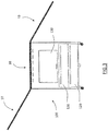
- an integrated apparatus is constituted by a transportable container on wheels 100, provided with a user interface, 110, for the interrogation, management and programming of an apparatus control unit, electrical connection sockets for the connection of external electric loads, hydraulic fittings of inlet and outlet for a water treatment device comprised in the apparatus, and at least one sliding drawer structure, 120, to which are mounted storage batteries, filters of the aforesaid water treatment device and / or other components of the apparatus which will be described below.
- To the upper surface of the storage unit 100 are connected photovoltaic modules, 10, in a manner already described in the aforementioned International Application WO 2013/093654 .
- photovoltaic modules 10 are particularly effective since it allows to have extremely contained overall dimensions of the apparatus during transportation and when it is not in use and at the same time, without removing from the apparatus the photovoltaic modules 10 a great amount of surface area of modules can be used which can in large part be tilted toward the sun to optimize the production of energy.
- the transportable container 10 advantageously has a compact shape of a parallelepiped with supporting frames and side panels for protection and insulation and is provided with a door, 130, which allows a large and convenient access to the inner space, extractable stabilizers which serve to stabilize the position of the apparatus when in use and useful also to avoid any danger of tipping apparatus after extraction of the drawer structures 120.
- the apparatus comprises first of all the aforementioned photovoltaic modules 10 which are advantageously high efficiency photovoltaic modules made of transparent polymer material resistant to UV radiation, a peak power of the single panel equal to or greater than 130Wp and operating temperatures from -40 ° to + 85 ° C, then these can be used to substantially any latitude.
- the photovoltaic modules 10 constitute, with most general sense, power generators in a current of energy, which will be cited in the following with the same reference. To this category also belong to the wind generators, which can be associated to the apparatus of the invention, in addition or alternative to the PV modules, to increase the energy that can be harvested from the apparatus.
- Wind generators particularly advantageous to be associated to the apparatus of the present invention are constituted by vertical-axis wind turbines with a nominal power of about 3 KW each.
- the current generators 10, which in the case of photovoltaic modules are certainly connected in strings, are connected to a DC / DC converter, 20, adapted to receive the DC power from one or more strings generators in continuous current and to transform it to output DC power with parameters stabilized.
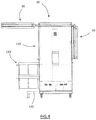
- a plurality of storage batteries, 30, are suitably housed in the lower part of the cabinet, with overall storage capacity advantageously comprised between 3 KVA and 30 KVA.
- said storage capacity are ensured by a plurality of identical Li-Ion batteries with elements sized 3.3 V and 160 Ah which are housed in the apparatus in a different number depending on the power of the specific model of an apparatus according to the invention.
- the batteries are mounted on a sliding drawer structure 120 of the transportable container 100 so that when it has to be provided for the replacement or maintenance their removal is particularly easy.
- the batteries are associated with corresponding charge means, 40, equipped with a battery management system that optimizes, according to known techniques, the recharging of the batteries avoiding overloads or other problems that could damage the batteries 30 or alter their optimal functioning.
- the apparatus further comprises, a DC / AC inverter, 50, an electronic switching module, 60, and a control unit 70, which altogether manage the storage of energy in the batteries 30 and its timely delivery to a plurality of users, 80, both in DC and in AC.
- the switching module 60 receives energy from the DC / DC converter 20 to transmit it to the charge means 40 and then to the batteries 30. In addition, the switching module 60 receives power from the batteries and via its own boost stage transforms it to supply the inverter DC / AC 50 with power at a determined voltage, advantageously 110V. In addition, the switching module 60 also provides power directly to DC users 80.
- the DC / AC inverter 50 is power supplied by the switching module 60 and provides AC power to AC users 80.
- the loads 80 are divided into at least two categories of users, that is to say a category of privileged users, 81 and a category of common utilities, 82.
- the control unit 70 via its own energy control module, 71, manages the switching module 60 and the DC / AC inverter 50 so that the power supply to the loads 80 takes into account, through their predefined and / or settable operating algorithms, the distribution of energy between privileged users 81 and common users 82 .
- the privileged users 81 includes all those appliances which are an integral part of the apparatus of the invention, while between the common utilities 82 there are the external loads that are supplied by the apparatus via appropriate sockets provided in a side panel of the container 100.
- a water treatment device, 200 is one of the AC privileged users 81 comprised in the apparatus of the invention.
- FIG. 6 A block diagram of a water treatment apparatus 200 advantageously housed in the transportable container 100 is shown in Figure 6 .
- a side panel of the container 100 is provided with at least a hydraulic input fitting, 250, and at least one hydraulic output fitting, 260, of the aforesaid water treatment device 200.
- the water to be treated is fed into a vessel for water to be treated, 270, in which samples of water before being treated are advantageously analysed by means of a suitable automatic analysis unit, 280.
- the main purpose of the analysis is to determine the level and type of contamination of the water to determine, also as a function of the type of use for which the treated water is intended (drinking water or not), the treatment or treatments to be performed.
- the treatment device 200 comprises a filtering section with osmotic membranes, 210, a ultrafiltration section with capillary and graphene membranes, 220, a possible ozone purification section, 240, and a germicidal UV rays section, 230, laid in a treated water collecting tank, 290.
- the hydraulic connections between the various sections are such that each of the aforementioned sections can be bypassed and that the water to be treated may be sent to the tank 290 or the treated water back to the water to be treated tank.
- the treatment device is managed by a water control module, 72, the control unit 70 of the apparatus, so that the water treatment takes place according to predefined and settable programs, depending on the type of use that must have the water treated and the type and degree of contamination of the inlet water, set in the control unit or detected by the analysis unit 280. For example, if the incoming water has a low contamination degree it can be executed just a purifying treatment in the osmosis filtration sections 210 and eventually in the germicidal UV rays section 230, while if the incoming water has a high contamination degree it is necessary to perform a preliminary purification in the ozone purification section 240, and then the water can be treated or not in the other sections depending on the use to be made of the treated water.
- the water treatment process described is particularly suitable for the production of drinking water from brackish water / salt and / or fresh water with particular contaminants that make it unsuitable for drinking.
- All or some of the treatment sections 210, 220, 230, 240 are advantageously installed integral with a extractable drawer structure 120 of the transportable container 100.In this way, the operations of standard maintenance of the water treatment device 200, such as the cleaning or replacement of filters, can take place in a very smooth way.
- a water treatment device comprised in the apparatus may also not include all the processing sections described above, or may comprise still other sections such as a desalination unit.
- some components of the water treatment device such as the water to be treated tank 270 and the treated water tank 290 may not be present or may be associated externally to the transportable container 100.
- a telecommunication system, 300 is also one of the privileged DC users 81.
- the telecommunication system 300 comprises a satellite communication module 310, suitable to provide satellite connection both for data communications and voice communications, and a module for generating a hot spot wireless network, 320.
- the telecommunication system 300 is able to create a local wireless network within an area of several kilometres, to which enabled general purpose devices can connect such as smartphones, tablets, notebooks, PC, or devices dedicated to specific tasks such as environmental monitoring devices or other. Thanks to the satellite communication module 310 the telecommunication system 300 allows for such devices that are within range of the wireless network to connect any device that can be reached by the satellite network, so in practice around the world, both for voice communications and for data communications.
- the telecommunication system is operated by a communications control module 73 of the control unit. Further, the foregoing features of the telecommunication system 300 also allow access to the control unit 70 not only by the interface 110 present on a side panel of the container 100, but also from portable devices recognized in the wireless network generated by module 320 and from devices connected to the apparatus by even very remote locations through the satellite communication module 310.
- the apparatus of the invention provides in a single transportable huosing a large number of appliances of primary importance such as energy supply, the water supply, the charging of electric vehicles and the possibility of communicate with the rest of the world, all with a view at having a minimum environmental impact as the system receives power exclusively from renewable sources.
- the composition of an apparatus according to the invention as described above allows an optimal management of the energy resources, performed by the control unit 70.
- the control unit 70 is programmed to control the electronic switching module 60 as a function of a predefined hierarchical order of importance of the users 80, giving preference to supplying a category of privileged users 81 compared to common users 82 if the remaining amount of energy in the battery 30 needs to be rationed.
- the privileged users 81 there are the water treatment device 200 and the telecommunication module 300 which, as above said, have a fundamental importance in the environments of use of the apparatus and allow a remote control of the apparatus itself.
- control unit 70 controls the electronic switching module as a function of parameters relating to the state of charge of the batteries 30 and of parameters related to the rate of production of energy by the DC generators 10.
- the generators 10 are photovoltaic modules, these are able to produce power and to feed the battery 30 only in the daytime period, so that during nightime may be necessary to ration the power supply to the users preferring the most important users, namely the appliances that are included in the category of privileged users 81.
- control unit 70 may also inhibit the power supply to the common loads 82 to prolong the power supply to the privileged users 81 as a function of the parameters relating to the state of charge of the batteries 30 and of parameters related to the rate of production of energy by the DC generators 10.As previously mentioned, among the privileged users are included, by default, the water treatment device 200 and the telecommunication module 300.
- This default setting of the control unit 70 can be modified, for example by inserting between the privileged users 81 one of the sockets of the side panel of the container 100 which will be intended for the connection of a user of particular importance, such as medical equipment or similar.
- the apparatus of the invention is characterized by a great flexibility of its different modules depending on the requirements of use.
Landscapes
- Engineering & Computer Science (AREA)
- Power Engineering (AREA)
- Life Sciences & Earth Sciences (AREA)
- Sustainable Development (AREA)
- Sustainable Energy (AREA)
- Charge And Discharge Circuits For Batteries Or The Like (AREA)
Claims (10)
- Transportierbar, integrierte, eigenständige Vorrichtung umfassend:- Gleichstromgeneratoren (10),- mindestens einen Gleichstrom/Gleichstrom-Wandler (20), der geeignet ist, die Gleichstromversorgung von einem oder mehreren Strängen der Gleichstromgeneratoren zu empfangen und sie in eine Ausgangs-Gleichstromversorgung bei einer bestimmten Spannung umzuwandeln;- Batterien zur Speicherung elektrischer Energie (30) und Lademittel (40), die mit einem Batteriemanagementsystem versehen sind;- einen Gleichstrom/Wechselstrom-Wechselrichter (50), der so ausgelegt ist, dass er Gleichstrom empfängt und ihn als Ausgang an einen oder mehrere daran angeschlossene Verbraucher, darunter mindestens eine Wasseraufbereitungsvorrichtung (200), liefert;- ein elektronisches Schaltmodul (60), das dazu ausgelegt ist, Gleichstrom von dem Gleichstrom/Gleichstrom-Wandler (20) und den Batterien (30) zu empfangen und Gleichstrom an den Gleichstrom/Wechselstrom-Wechselrichter (50) und beliebige Gleichstromverbraucher zu liefern,- eine Steuereinheit (70), die ein Leistungssteuermodul (71) zur Steuerung der Erzeugung und Zufuhr von Energie und ein Wassersteuermodul (72) zur Steuerung des Betriebs der Wasserbehandlungsvorrichtung (200) umfasst;wobei das Leistungssteuermodul (71) den Betrieb des Gleichstrom/Gleichstrom-Wandlers (20), des elektronischen Schaltmoduls (60) und des Gleichstrom/Wechselstrom-Wechselrichters (50) steuert, um die Energieversorgung aller Benutzer zu verwalten, und
wobei der mindestens eine Gleichstrom/Gleichstrom-Wandler (20), die Batterien zur Speicherung elektrischer Energie (30), der Gleichstrom/Wechselstrom-Wechselrichter (50), das elektronische Schaltmodul (60) und die Steuereinheit (70) in einem transportierbarn Behälter auf Rädern (100) enthalten sind, der mit einer Benutzerschnittstelle (110) für die Abfrage, Verwaltung und Programmierung der Steuereinheit (70), Steckdosen für den Anschluss externer elektrischer Lasten, Eingangs- (250) und Ausgangshydraulikanschlüssen (260) der Wasseraufbereitungsvorrichtung (200) versehen ist;
dadurch gekennzeichnet, dass der transportierbar Behälter mindestens eine verschiebbare Schubladenstruktur (120) umfasst, auf der die Batterien (30) so angebracht sind, dass die Wartungsvorgänge der Batterien (30) leicht durch Herausziehen der verschiebbaren Schubladenstruktur (120) durchgeführt werden können. - Transportierbar, integrierte, eigenständige Vorrichtung nach Anspruch 1, dadurch gekennzeichnet, dass die Batterien eine Vielzahl von identischen Li-Ion/Pb-Batterien umfassen und dass der Gleichstrom/Wechselstrom-Wechselrichter geeignet ist, am Eingang eine Vielzahl von unterschiedlichen Spannungen zu empfangen, die eine Funktion der Anzahl der in dem Gerät installierten Batterien sind.
- Transportierbar, integrierte, eigenständige Vorrichtung nach Anspruch 1 oder 2, dadurch gekennzeichnet, dass die Wasseraufbereitungsvorrichtung (200) eine Vielzahl von Behandlungsabschnitten umfasst, die mindestens einen Umkehrosmose-Filterabschnitt (210), mindestens einen Ultrafiltrationsabschnitt (220) und mindestens einen UV-Strahlen-Behandlungsabschnitt (230) umfassen.
- Transportierbar, integrierte, eigenständige Vorrichtung nach dem vorhergehenden Anspruch, dadurch gekennzeichnet, dass die Wasseraufbereitungsvorrichtung (200) mindestens einen Ozon-Sanitisierungsabschnitt (240) für Wasser für den Sanitär-/Trinkgebrauch umfasst.
- Transportierbar, integrierte, eigenständige Vorrichtung nach Anspruch 3 oder 4, dadurch gekennzeichnet, dass die Behandlungsabschnitte hydraulisch mit einer Einlassleitung für zu behandelndes Wasser (201) und mit einer Leitung für die Ausgabe von behandeltem Wasser (202) verbunden sind, so dass jeder der Abschnitte durch das Wassersteuermodul (72) aktiviert oder umgangen werden kann.
- Transportierbar, integrierte, eigenständige Vorrichtung nach dem vorhergehenden Anspruch, dadurch gekennzeichnet, dass die Wasserbehandlungsvorrichtung Wasseranalyseeinheiten (205) für das behandelte Wasser und das zu behandelnde Wasser enthält und dass das Wassersteuermodul (72) die Aktivierung oder Umgehung der Behandlungsabschnitte in Abhängigkeit von den Ergebnissen der von der Analyseeinheit (205) durchgeführten Wasseranalyse steuert.
- Transportierbar, integrierte, eigenständige Vorrichtung nach einem der vorhergehenden Ansprüche, dadurch gekennzeichnet, dass sie ein Telekommunikationsmodul (300) umfasst, das mit einem Satellitenkommunikationsmodul (310) für Sprach- und Datensatellitenkommunikation und einem drahtlosen Hot-Spot-Netzwerkmodul (320) versehen ist.
- Transportierbar, integrierte, eigenständige Vorrichtung nach dem vorhergehenden Anspruch, dadurch gekennzeichnet, dass die Steuereinheit (70) ein Kommunikationssteuermodul (73) umfasst, das geeignet ist, das Telekommunikationsmodul (300) zu verwalten, und dass das Telekommunikationsmodul (300) über das elektronische Schaltmodul (60) mit Gleichstrom versorgt wird.
- Transportierbar, integrierte, eigenständige Vorrichtung nach Anspruch 1 und 4, dadurch gekennzeichnet, dass der transportierbar Behälter auf Rädern (100) mit mindestens einer weiteren verschiebbaren Schubladenstruktur (120) versehen ist, auf der Komponenten der Behandlungsabschnitte (210, 220, 230, 240) der Wasserbehandlungsvorrichtung (200) montiert sind.
- Transportierbar, integrierte, eigenständige Vorrichtung nach Anspruch 1 und 4, dadurch gekennzeichnet, dass der transportierbar Behälter auf Rädern (100) eine kompakte Form eines Parallelepipeds mit Stützrahmen und Seitenpaneelen zum Schutz und zur Isolierung aufweist und mit einer Tür (130) versehen ist, die einen großen und bequemen Zugang zum Innenraum ermöglicht, sowie mit ausziehbaren Stabilisatoren, die dazu dienen, die Position der Vorrichtung im Gebrauch zu stabilisieren, und die auch nützlich sind, um jede Gefahr eines Kippens der Vorrichtung nach dem Herausziehen der Schubladenstrukturen (120) zu vermeiden.
Applications Claiming Priority (1)
| Application Number | Priority Date | Filing Date | Title |
|---|---|---|---|
| PCT/IT2015/000294 WO2017094033A1 (en) | 2015-12-04 | 2015-12-04 | Transportable integrated stand-alone apparatus |
Publications (2)
| Publication Number | Publication Date |
|---|---|
| EP3446394A1 EP3446394A1 (de) | 2019-02-27 |
| EP3446394B1 true EP3446394B1 (de) | 2021-04-28 |
Family
ID=55527934
Family Applications (1)
| Application Number | Title | Priority Date | Filing Date |
|---|---|---|---|
| EP15843065.2A Active EP3446394B1 (de) | 2015-12-04 | 2015-12-04 | Transportable integrierte eigenständige vorrichtung |
Country Status (2)
| Country | Link |
|---|---|
| EP (1) | EP3446394B1 (de) |
| WO (1) | WO2017094033A1 (de) |
Families Citing this family (4)
| Publication number | Priority date | Publication date | Assignee | Title |
|---|---|---|---|---|
| IT201700097661A1 (it) * | 2017-08-30 | 2019-03-02 | Sts Italia S R L | Stazione trasportabile per la produzione di energia fotovoltaica |
| CN107707180A (zh) * | 2017-11-08 | 2018-02-16 | 繁昌县晶鑫贸易有限公司 | 一种新型太阳能发电设备 |
| CN207868860U (zh) * | 2018-05-15 | 2018-09-14 | 米亚索能光伏科技有限公司 | 一种太阳能电源装置、电源应急拉杆箱及电源系统 |
| GR1010207B (el) * | 2021-06-22 | 2022-03-21 | Ιωαννης Βασιλειου Χατζησαββας | Συστημα διαχειρισης περισσειας ενεργειας αυτονομης φωτοβολταϊκης ή αιολικης εγκαταστασης |
Family Cites Families (6)
| Publication number | Priority date | Publication date | Assignee | Title |
|---|---|---|---|---|
| US6396239B1 (en) * | 2001-04-06 | 2002-05-28 | William M. Benn | Portable solar generator |
| US8200373B2 (en) * | 2009-04-23 | 2012-06-12 | Pentair Water Pool And Spa, Inc. | Energy production and consumption matching system |
| US20130106191A1 (en) * | 2011-07-26 | 2013-05-02 | Claudia Iovino | Renewable mobile resource station |
| US9515489B2 (en) * | 2011-11-07 | 2016-12-06 | Global Link Co., Ltd. | Feed system to be used in residence such as multi-unit apartment complex |
| US9236751B2 (en) * | 2012-03-09 | 2016-01-12 | Aspect Solar Pte Ltd | Portable modular sun-tracking solar energy receiver system |
| US9793429B2 (en) * | 2013-12-01 | 2017-10-17 | Alfred Hyamo Bedell | Photovoltaic intensification system using solar tracking concentrators and heat exchangers |
-
2015
- 2015-12-04 WO PCT/IT2015/000294 patent/WO2017094033A1/en not_active Ceased
- 2015-12-04 EP EP15843065.2A patent/EP3446394B1/de active Active
Non-Patent Citations (1)
| Title |
|---|
| None * |
Also Published As
| Publication number | Publication date |
|---|---|
| EP3446394A1 (de) | 2019-02-27 |
| WO2017094033A1 (en) | 2017-06-08 |
Similar Documents
| Publication | Publication Date | Title |
|---|---|---|
| US7150153B2 (en) | Renewable portable stored energy power generating apparatus with alternate water source capability | |
| US20170201098A1 (en) | Photovoltaic microstorage microinverter | |
| EP3446394B1 (de) | Transportable integrierte eigenständige vorrichtung | |
| Soric et al. | Eausmose project desalination by reverse osmosis and batteryless solar energy: Design for a 1 m3 per day delivery | |
| US20080236654A1 (en) | WINDOW CONSTRUCTION COMBININB NiMH TECHNOLOGY AND SOLAR POWER | |
| CN105846419B (zh) | 基于直流微电网的光伏、柴油互补供电系统 | |
| Tzen et al. | Design and development of a hybrid autonomous system for seawater desalination | |
| CN205740453U (zh) | 苦咸水淡化系统 | |
| EP2795113A2 (de) | Unabhängige kombinierte vorrichtung zur gewinnung elektrischer energie und zur trinkwasseraufbereitung | |
| WO2014174460A1 (en) | A module for storing/drawing electricity in/from an electric accumulator applicable to photovoltaic systems, a photovoltaic system and a method of upgrading a photovoltaic system | |
| KR20160098860A (ko) | 배터리 에너지 저장 시스템을 포함하는 전력 공급 시스템 | |
| DE102008059293A1 (de) | Solar-Stromversorgung | |
| JP2013153572A (ja) | 電力供給制御装置及び電力供給制御方法 | |
| CN104868825A (zh) | 太阳能集装箱系统 | |
| KR102534877B1 (ko) | 태양광발전 장치 | |
| KR101957197B1 (ko) | 태양광발전 시스템 | |
| EP3123583A1 (de) | Mono-inverter | |
| JP6093053B2 (ja) | 太陽光発電データ収集装置 | |
| Mansur et al. | Design and Performance Analysis of Solar PV DC Power System for Disaster Relief Centre using PVsyst | |
| GB2482114A (en) | Direct current power transmission grid | |
| WO2017197437A1 (en) | Solar energy collection system | |
| CN223135240U (zh) | 一种基于光伏发电的净水取水设备 | |
| Bhattacharya et al. | Design and evaluation of a hybrid solar-powered water purification and energy system for rural and semi-urban households | |
| Despotović et al. | Design and Implementation of a Hybrid Power for Telecommunication and Measuring Remote Station of the Surveillance, Alert and Warning System | |
| KR20150029809A (ko) | 계통 연계형 태양광발전 장치 |
Legal Events
| Date | Code | Title | Description |
|---|---|---|---|
| STAA | Information on the status of an ep patent application or granted ep patent |
Free format text: STATUS: THE INTERNATIONAL PUBLICATION HAS BEEN MADE |
|
| PUAI | Public reference made under article 153(3) epc to a published international application that has entered the european phase |
Free format text: ORIGINAL CODE: 0009012 |
|
| STAA | Information on the status of an ep patent application or granted ep patent |
Free format text: STATUS: REQUEST FOR EXAMINATION WAS MADE |
|
| 17P | Request for examination filed |
Effective date: 20180705 |
|
| AK | Designated contracting states |
Kind code of ref document: A1 Designated state(s): AL AT BE BG CH CY CZ DE DK EE ES FI FR GB GR HR HU IE IS IT LI LT LU LV MC MK MT NL NO PL PT RO RS SE SI SK SM TR |
|
| AX | Request for extension of the european patent |
Extension state: BA ME |
|
| DAV | Request for validation of the european patent (deleted) | ||
| DAX | Request for extension of the european patent (deleted) | ||
| STAA | Information on the status of an ep patent application or granted ep patent |
Free format text: STATUS: EXAMINATION IS IN PROGRESS |
|
| 17Q | First examination report despatched |
Effective date: 20191028 |
|
| REG | Reference to a national code |
Ref country code: DE Ref legal event code: R079 Ref document number: 602015068778 Country of ref document: DE Free format text: PREVIOUS MAIN CLASS: H02J0007350000 Ipc: H02S0010120000 |
|
| RIC1 | Information provided on ipc code assigned before grant |
Ipc: H02S 10/20 20140101ALI20200922BHEP Ipc: H02S 40/32 20140101ALI20200922BHEP Ipc: H02S 20/30 20140101ALI20200922BHEP Ipc: H02S 10/12 20140101AFI20200922BHEP Ipc: H02S 40/34 20140101ALI20200922BHEP Ipc: H02S 10/30 20140101ALI20200922BHEP Ipc: H02S 30/20 20140101ALI20200922BHEP Ipc: H02J 7/35 20060101ALI20200922BHEP |
|
| GRAP | Despatch of communication of intention to grant a patent |
Free format text: ORIGINAL CODE: EPIDOSNIGR1 |
|
| STAA | Information on the status of an ep patent application or granted ep patent |
Free format text: STATUS: GRANT OF PATENT IS INTENDED |
|
| INTG | Intention to grant announced |
Effective date: 20201120 |
|
| INTG | Intention to grant announced |
Effective date: 20201124 |
|
| GRAS | Grant fee paid |
Free format text: ORIGINAL CODE: EPIDOSNIGR3 |
|
| GRAA | (expected) grant |
Free format text: ORIGINAL CODE: 0009210 |
|
| STAA | Information on the status of an ep patent application or granted ep patent |
Free format text: STATUS: THE PATENT HAS BEEN GRANTED |
|
| AK | Designated contracting states |
Kind code of ref document: B1 Designated state(s): AL AT BE BG CH CY CZ DE DK EE ES FI FR GB GR HR HU IE IS IT LI LT LU LV MC MK MT NL NO PL PT RO RS SE SI SK SM TR |
|
| REG | Reference to a national code |
Ref country code: GB Ref legal event code: FG4D |
|
| REG | Reference to a national code |
Ref country code: CH Ref legal event code: EP |
|
| REG | Reference to a national code |
Ref country code: AT Ref legal event code: REF Ref document number: 1388287 Country of ref document: AT Kind code of ref document: T Effective date: 20210515 |
|
| REG | Reference to a national code |
Ref country code: DE Ref legal event code: R096 Ref document number: 602015068778 Country of ref document: DE |
|
| REG | Reference to a national code |
Ref country code: IE Ref legal event code: FG4D |
|
| REG | Reference to a national code |
Ref country code: LT Ref legal event code: MG9D |
|
| REG | Reference to a national code |
Ref country code: AT Ref legal event code: MK05 Ref document number: 1388287 Country of ref document: AT Kind code of ref document: T Effective date: 20210428 |
|
| PG25 | Lapsed in a contracting state [announced via postgrant information from national office to epo] |
Ref country code: FI Free format text: LAPSE BECAUSE OF FAILURE TO SUBMIT A TRANSLATION OF THE DESCRIPTION OR TO PAY THE FEE WITHIN THE PRESCRIBED TIME-LIMIT Effective date: 20210428 Ref country code: LT Free format text: LAPSE BECAUSE OF FAILURE TO SUBMIT A TRANSLATION OF THE DESCRIPTION OR TO PAY THE FEE WITHIN THE PRESCRIBED TIME-LIMIT Effective date: 20210428 Ref country code: NL Free format text: LAPSE BECAUSE OF FAILURE TO SUBMIT A TRANSLATION OF THE DESCRIPTION OR TO PAY THE FEE WITHIN THE PRESCRIBED TIME-LIMIT Effective date: 20210428 Ref country code: HR Free format text: LAPSE BECAUSE OF FAILURE TO SUBMIT A TRANSLATION OF THE DESCRIPTION OR TO PAY THE FEE WITHIN THE PRESCRIBED TIME-LIMIT Effective date: 20210428 Ref country code: BG Free format text: LAPSE BECAUSE OF FAILURE TO SUBMIT A TRANSLATION OF THE DESCRIPTION OR TO PAY THE FEE WITHIN THE PRESCRIBED TIME-LIMIT Effective date: 20210728 Ref country code: AT Free format text: LAPSE BECAUSE OF FAILURE TO SUBMIT A TRANSLATION OF THE DESCRIPTION OR TO PAY THE FEE WITHIN THE PRESCRIBED TIME-LIMIT Effective date: 20210428 |
|
| PG25 | Lapsed in a contracting state [announced via postgrant information from national office to epo] |
Ref country code: LV Free format text: LAPSE BECAUSE OF FAILURE TO SUBMIT A TRANSLATION OF THE DESCRIPTION OR TO PAY THE FEE WITHIN THE PRESCRIBED TIME-LIMIT Effective date: 20210428 Ref country code: IS Free format text: LAPSE BECAUSE OF FAILURE TO SUBMIT A TRANSLATION OF THE DESCRIPTION OR TO PAY THE FEE WITHIN THE PRESCRIBED TIME-LIMIT Effective date: 20210828 Ref country code: GR Free format text: LAPSE BECAUSE OF FAILURE TO SUBMIT A TRANSLATION OF THE DESCRIPTION OR TO PAY THE FEE WITHIN THE PRESCRIBED TIME-LIMIT Effective date: 20210729 Ref country code: NO Free format text: LAPSE BECAUSE OF FAILURE TO SUBMIT A TRANSLATION OF THE DESCRIPTION OR TO PAY THE FEE WITHIN THE PRESCRIBED TIME-LIMIT Effective date: 20210728 Ref country code: PT Free format text: LAPSE BECAUSE OF FAILURE TO SUBMIT A TRANSLATION OF THE DESCRIPTION OR TO PAY THE FEE WITHIN THE PRESCRIBED TIME-LIMIT Effective date: 20210830 Ref country code: PL Free format text: LAPSE BECAUSE OF FAILURE TO SUBMIT A TRANSLATION OF THE DESCRIPTION OR TO PAY THE FEE WITHIN THE PRESCRIBED TIME-LIMIT Effective date: 20210428 Ref country code: RS Free format text: LAPSE BECAUSE OF FAILURE TO SUBMIT A TRANSLATION OF THE DESCRIPTION OR TO PAY THE FEE WITHIN THE PRESCRIBED TIME-LIMIT Effective date: 20210428 Ref country code: SE Free format text: LAPSE BECAUSE OF FAILURE TO SUBMIT A TRANSLATION OF THE DESCRIPTION OR TO PAY THE FEE WITHIN THE PRESCRIBED TIME-LIMIT Effective date: 20210428 |
|
| REG | Reference to a national code |
Ref country code: NL Ref legal event code: MP Effective date: 20210428 |
|
| PG25 | Lapsed in a contracting state [announced via postgrant information from national office to epo] |
Ref country code: SM Free format text: LAPSE BECAUSE OF FAILURE TO SUBMIT A TRANSLATION OF THE DESCRIPTION OR TO PAY THE FEE WITHIN THE PRESCRIBED TIME-LIMIT Effective date: 20210428 Ref country code: SK Free format text: LAPSE BECAUSE OF FAILURE TO SUBMIT A TRANSLATION OF THE DESCRIPTION OR TO PAY THE FEE WITHIN THE PRESCRIBED TIME-LIMIT Effective date: 20210428 Ref country code: EE Free format text: LAPSE BECAUSE OF FAILURE TO SUBMIT A TRANSLATION OF THE DESCRIPTION OR TO PAY THE FEE WITHIN THE PRESCRIBED TIME-LIMIT Effective date: 20210428 Ref country code: CZ Free format text: LAPSE BECAUSE OF FAILURE TO SUBMIT A TRANSLATION OF THE DESCRIPTION OR TO PAY THE FEE WITHIN THE PRESCRIBED TIME-LIMIT Effective date: 20210428 Ref country code: DK Free format text: LAPSE BECAUSE OF FAILURE TO SUBMIT A TRANSLATION OF THE DESCRIPTION OR TO PAY THE FEE WITHIN THE PRESCRIBED TIME-LIMIT Effective date: 20210428 Ref country code: RO Free format text: LAPSE BECAUSE OF FAILURE TO SUBMIT A TRANSLATION OF THE DESCRIPTION OR TO PAY THE FEE WITHIN THE PRESCRIBED TIME-LIMIT Effective date: 20210428 Ref country code: ES Free format text: LAPSE BECAUSE OF FAILURE TO SUBMIT A TRANSLATION OF THE DESCRIPTION OR TO PAY THE FEE WITHIN THE PRESCRIBED TIME-LIMIT Effective date: 20210428 |
|
| REG | Reference to a national code |
Ref country code: DE Ref legal event code: R097 Ref document number: 602015068778 Country of ref document: DE |
|
| PLBE | No opposition filed within time limit |
Free format text: ORIGINAL CODE: 0009261 |
|
| STAA | Information on the status of an ep patent application or granted ep patent |
Free format text: STATUS: NO OPPOSITION FILED WITHIN TIME LIMIT |
|
| 26N | No opposition filed |
Effective date: 20220131 |
|
| PG25 | Lapsed in a contracting state [announced via postgrant information from national office to epo] |
Ref country code: IS Free format text: LAPSE BECAUSE OF FAILURE TO SUBMIT A TRANSLATION OF THE DESCRIPTION OR TO PAY THE FEE WITHIN THE PRESCRIBED TIME-LIMIT Effective date: 20210828 Ref country code: AL Free format text: LAPSE BECAUSE OF FAILURE TO SUBMIT A TRANSLATION OF THE DESCRIPTION OR TO PAY THE FEE WITHIN THE PRESCRIBED TIME-LIMIT Effective date: 20210428 |
|
| REG | Reference to a national code |
Ref country code: DE Ref legal event code: R119 Ref document number: 602015068778 Country of ref document: DE |
|
| PG25 | Lapsed in a contracting state [announced via postgrant information from national office to epo] |
Ref country code: MC Free format text: LAPSE BECAUSE OF FAILURE TO SUBMIT A TRANSLATION OF THE DESCRIPTION OR TO PAY THE FEE WITHIN THE PRESCRIBED TIME-LIMIT Effective date: 20210428 |
|
| REG | Reference to a national code |
Ref country code: CH Ref legal event code: PL |
|
| GBPC | Gb: european patent ceased through non-payment of renewal fee |
Effective date: 20211204 |
|
| REG | Reference to a national code |
Ref country code: BE Ref legal event code: MM Effective date: 20211231 |
|
| PG25 | Lapsed in a contracting state [announced via postgrant information from national office to epo] |
Ref country code: LU Free format text: LAPSE BECAUSE OF NON-PAYMENT OF DUE FEES Effective date: 20211204 Ref country code: IE Free format text: LAPSE BECAUSE OF NON-PAYMENT OF DUE FEES Effective date: 20211204 Ref country code: GB Free format text: LAPSE BECAUSE OF NON-PAYMENT OF DUE FEES Effective date: 20211204 Ref country code: DE Free format text: LAPSE BECAUSE OF NON-PAYMENT OF DUE FEES Effective date: 20220701 |
|
| PG25 | Lapsed in a contracting state [announced via postgrant information from national office to epo] |
Ref country code: FR Free format text: LAPSE BECAUSE OF NON-PAYMENT OF DUE FEES Effective date: 20211231 Ref country code: BE Free format text: LAPSE BECAUSE OF NON-PAYMENT OF DUE FEES Effective date: 20211231 |
|
| PG25 | Lapsed in a contracting state [announced via postgrant information from national office to epo] |
Ref country code: LI Free format text: LAPSE BECAUSE OF NON-PAYMENT OF DUE FEES Effective date: 20211231 Ref country code: CH Free format text: LAPSE BECAUSE OF NON-PAYMENT OF DUE FEES Effective date: 20211231 |
|
| PG25 | Lapsed in a contracting state [announced via postgrant information from national office to epo] |
Ref country code: CY Free format text: LAPSE BECAUSE OF FAILURE TO SUBMIT A TRANSLATION OF THE DESCRIPTION OR TO PAY THE FEE WITHIN THE PRESCRIBED TIME-LIMIT Effective date: 20210428 |
|
| PG25 | Lapsed in a contracting state [announced via postgrant information from national office to epo] |
Ref country code: HU Free format text: LAPSE BECAUSE OF FAILURE TO SUBMIT A TRANSLATION OF THE DESCRIPTION OR TO PAY THE FEE WITHIN THE PRESCRIBED TIME-LIMIT; INVALID AB INITIO Effective date: 20151204 |
|
| PG25 | Lapsed in a contracting state [announced via postgrant information from national office to epo] |
Ref country code: MK Free format text: LAPSE BECAUSE OF FAILURE TO SUBMIT A TRANSLATION OF THE DESCRIPTION OR TO PAY THE FEE WITHIN THE PRESCRIBED TIME-LIMIT Effective date: 20210428 |
|
| PG25 | Lapsed in a contracting state [announced via postgrant information from national office to epo] |
Ref country code: MT Free format text: LAPSE BECAUSE OF FAILURE TO SUBMIT A TRANSLATION OF THE DESCRIPTION OR TO PAY THE FEE WITHIN THE PRESCRIBED TIME-LIMIT Effective date: 20210428 |
|
| PG25 | Lapsed in a contracting state [announced via postgrant information from national office to epo] |
Ref country code: TR Free format text: LAPSE BECAUSE OF FAILURE TO SUBMIT A TRANSLATION OF THE DESCRIPTION OR TO PAY THE FEE WITHIN THE PRESCRIBED TIME-LIMIT Effective date: 20210428 |
|
| PGFP | Annual fee paid to national office [announced via postgrant information from national office to epo] |
Ref country code: IT Payment date: 20251222 Year of fee payment: 11 |