EP3445719B1 - Wasseraufbereitungsvorrichtung - Google Patents
Wasseraufbereitungsvorrichtung Download PDFInfo
- Publication number
- EP3445719B1 EP3445719B1 EP17721562.1A EP17721562A EP3445719B1 EP 3445719 B1 EP3445719 B1 EP 3445719B1 EP 17721562 A EP17721562 A EP 17721562A EP 3445719 B1 EP3445719 B1 EP 3445719B1
- Authority
- EP
- European Patent Office
- Prior art keywords
- filter
- adsorption
- filter element
- unit
- housing
- Prior art date
- Legal status (The legal status is an assumption and is not a legal conclusion. Google has not performed a legal analysis and makes no representation as to the accuracy of the status listed.)
- Active
Links
Images



Classifications
-
- C—CHEMISTRY; METALLURGY
- C02—TREATMENT OF WATER, WASTE WATER, SEWAGE, OR SLUDGE
- C02F—TREATMENT OF WATER, WASTE WATER, SEWAGE, OR SLUDGE
- C02F1/00—Treatment of water, waste water, or sewage
- C02F1/001—Processes for the treatment of water whereby the filtration technique is of importance
- C02F1/003—Processes for the treatment of water whereby the filtration technique is of importance using household-type filters for producing potable water, e.g. pitchers, bottles, faucet mounted devices
-
- B—PERFORMING OPERATIONS; TRANSPORTING
- B01—PHYSICAL OR CHEMICAL PROCESSES OR APPARATUS IN GENERAL
- B01D—SEPARATION
- B01D61/00—Processes of separation using semi-permeable membranes, e.g. dialysis, osmosis or ultrafiltration; Apparatus, accessories or auxiliary operations specially adapted therefor
- B01D61/14—Ultrafiltration; Microfiltration
- B01D61/147—Microfiltration
-
- B—PERFORMING OPERATIONS; TRANSPORTING
- B01—PHYSICAL OR CHEMICAL PROCESSES OR APPARATUS IN GENERAL
- B01D—SEPARATION
- B01D63/00—Apparatus in general for separation processes using semi-permeable membranes
- B01D63/02—Hollow fibre modules
- B01D63/024—Hollow fibre modules with a single potted end
- B01D63/0241—Hollow fibre modules with a single potted end being U-shaped
-
- B—PERFORMING OPERATIONS; TRANSPORTING
- B01—PHYSICAL OR CHEMICAL PROCESSES OR APPARATUS IN GENERAL
- B01D—SEPARATION
- B01D69/00—Semi-permeable membranes for separation processes or apparatus characterised by their form, structure or properties; Manufacturing processes specially adapted therefor
- B01D69/08—Hollow fibre membranes
-
- B—PERFORMING OPERATIONS; TRANSPORTING
- B01—PHYSICAL OR CHEMICAL PROCESSES OR APPARATUS IN GENERAL
- B01J—CHEMICAL OR PHYSICAL PROCESSES, e.g. CATALYSIS OR COLLOID CHEMISTRY; THEIR RELEVANT APPARATUS
- B01J20/00—Solid sorbent compositions or filter aid compositions; Sorbents for chromatography; Processes for preparing, regenerating or reactivating thereof
- B01J20/02—Solid sorbent compositions or filter aid compositions; Sorbents for chromatography; Processes for preparing, regenerating or reactivating thereof comprising inorganic material
- B01J20/10—Solid sorbent compositions or filter aid compositions; Sorbents for chromatography; Processes for preparing, regenerating or reactivating thereof comprising inorganic material comprising silica or silicate
- B01J20/12—Naturally occurring clays or bleaching earth
-
- B—PERFORMING OPERATIONS; TRANSPORTING
- B01—PHYSICAL OR CHEMICAL PROCESSES OR APPARATUS IN GENERAL
- B01J—CHEMICAL OR PHYSICAL PROCESSES, e.g. CATALYSIS OR COLLOID CHEMISTRY; THEIR RELEVANT APPARATUS
- B01J20/00—Solid sorbent compositions or filter aid compositions; Sorbents for chromatography; Processes for preparing, regenerating or reactivating thereof
- B01J20/02—Solid sorbent compositions or filter aid compositions; Sorbents for chromatography; Processes for preparing, regenerating or reactivating thereof comprising inorganic material
- B01J20/20—Solid sorbent compositions or filter aid compositions; Sorbents for chromatography; Processes for preparing, regenerating or reactivating thereof comprising inorganic material comprising free carbon; comprising carbon obtained by carbonising processes
-
- B—PERFORMING OPERATIONS; TRANSPORTING
- B01—PHYSICAL OR CHEMICAL PROCESSES OR APPARATUS IN GENERAL
- B01J—CHEMICAL OR PHYSICAL PROCESSES, e.g. CATALYSIS OR COLLOID CHEMISTRY; THEIR RELEVANT APPARATUS
- B01J20/00—Solid sorbent compositions or filter aid compositions; Sorbents for chromatography; Processes for preparing, regenerating or reactivating thereof
- B01J20/22—Solid sorbent compositions or filter aid compositions; Sorbents for chromatography; Processes for preparing, regenerating or reactivating thereof comprising organic material
- B01J20/26—Synthetic macromolecular compounds
-
- C—CHEMISTRY; METALLURGY
- C02—TREATMENT OF WATER, WASTE WATER, SEWAGE, OR SLUDGE
- C02F—TREATMENT OF WATER, WASTE WATER, SEWAGE, OR SLUDGE
- C02F1/00—Treatment of water, waste water, or sewage
- C02F1/28—Treatment of water, waste water, or sewage by sorption
- C02F1/281—Treatment of water, waste water, or sewage by sorption using inorganic sorbents
-
- C—CHEMISTRY; METALLURGY
- C02—TREATMENT OF WATER, WASTE WATER, SEWAGE, OR SLUDGE
- C02F—TREATMENT OF WATER, WASTE WATER, SEWAGE, OR SLUDGE
- C02F1/00—Treatment of water, waste water, or sewage
- C02F1/28—Treatment of water, waste water, or sewage by sorption
- C02F1/283—Treatment of water, waste water, or sewage by sorption using coal, charred products, or inorganic mixtures containing them
-
- C—CHEMISTRY; METALLURGY
- C02—TREATMENT OF WATER, WASTE WATER, SEWAGE, OR SLUDGE
- C02F—TREATMENT OF WATER, WASTE WATER, SEWAGE, OR SLUDGE
- C02F1/00—Treatment of water, waste water, or sewage
- C02F1/28—Treatment of water, waste water, or sewage by sorption
- C02F1/285—Treatment of water, waste water, or sewage by sorption using synthetic organic sorbents
-
- C—CHEMISTRY; METALLURGY
- C02—TREATMENT OF WATER, WASTE WATER, SEWAGE, OR SLUDGE
- C02F—TREATMENT OF WATER, WASTE WATER, SEWAGE, OR SLUDGE
- C02F1/00—Treatment of water, waste water, or sewage
- C02F1/28—Treatment of water, waste water, or sewage by sorption
- C02F1/286—Treatment of water, waste water, or sewage by sorption using natural organic sorbents or derivatives thereof
-
- C—CHEMISTRY; METALLURGY
- C02—TREATMENT OF WATER, WASTE WATER, SEWAGE, OR SLUDGE
- C02F—TREATMENT OF WATER, WASTE WATER, SEWAGE, OR SLUDGE
- C02F1/00—Treatment of water, waste water, or sewage
- C02F1/42—Treatment of water, waste water, or sewage by ion-exchange
-
- C—CHEMISTRY; METALLURGY
- C02—TREATMENT OF WATER, WASTE WATER, SEWAGE, OR SLUDGE
- C02F—TREATMENT OF WATER, WASTE WATER, SEWAGE, OR SLUDGE
- C02F1/00—Treatment of water, waste water, or sewage
- C02F1/44—Treatment of water, waste water, or sewage by dialysis, osmosis or reverse osmosis
-
- C—CHEMISTRY; METALLURGY
- C02—TREATMENT OF WATER, WASTE WATER, SEWAGE, OR SLUDGE
- C02F—TREATMENT OF WATER, WASTE WATER, SEWAGE, OR SLUDGE
- C02F1/00—Treatment of water, waste water, or sewage
- C02F1/44—Treatment of water, waste water, or sewage by dialysis, osmosis or reverse osmosis
- C02F1/444—Treatment of water, waste water, or sewage by dialysis, osmosis or reverse osmosis by ultrafiltration or microfiltration
-
- C—CHEMISTRY; METALLURGY
- C02—TREATMENT OF WATER, WASTE WATER, SEWAGE, OR SLUDGE
- C02F—TREATMENT OF WATER, WASTE WATER, SEWAGE, OR SLUDGE
- C02F9/00—Multistage treatment of water, waste water or sewage
- C02F9/20—Portable or detachable small-scale multistage treatment devices, e.g. point of use or laboratory water purification systems
-
- C—CHEMISTRY; METALLURGY
- C02—TREATMENT OF WATER, WASTE WATER, SEWAGE, OR SLUDGE
- C02F—TREATMENT OF WATER, WASTE WATER, SEWAGE, OR SLUDGE
- C02F1/00—Treatment of water, waste water, or sewage
- C02F1/42—Treatment of water, waste water, or sewage by ion-exchange
- C02F2001/422—Treatment of water, waste water, or sewage by ion-exchange using anionic exchangers
-
- C—CHEMISTRY; METALLURGY
- C02—TREATMENT OF WATER, WASTE WATER, SEWAGE, OR SLUDGE
- C02F—TREATMENT OF WATER, WASTE WATER, SEWAGE, OR SLUDGE
- C02F1/00—Treatment of water, waste water, or sewage
- C02F1/42—Treatment of water, waste water, or sewage by ion-exchange
- C02F2001/425—Treatment of water, waste water, or sewage by ion-exchange using cation exchangers
-
- C—CHEMISTRY; METALLURGY
- C02—TREATMENT OF WATER, WASTE WATER, SEWAGE, OR SLUDGE
- C02F—TREATMENT OF WATER, WASTE WATER, SEWAGE, OR SLUDGE
- C02F2101/00—Nature of the contaminant
- C02F2101/10—Inorganic compounds
- C02F2101/20—Heavy metals or heavy metal compounds
-
- C—CHEMISTRY; METALLURGY
- C02—TREATMENT OF WATER, WASTE WATER, SEWAGE, OR SLUDGE
- C02F—TREATMENT OF WATER, WASTE WATER, SEWAGE, OR SLUDGE
- C02F2101/00—Nature of the contaminant
- C02F2101/30—Organic compounds
- C02F2101/305—Endocrine disruptive agents
-
- C—CHEMISTRY; METALLURGY
- C02—TREATMENT OF WATER, WASTE WATER, SEWAGE, OR SLUDGE
- C02F—TREATMENT OF WATER, WASTE WATER, SEWAGE, OR SLUDGE
- C02F2101/00—Nature of the contaminant
- C02F2101/30—Organic compounds
- C02F2101/306—Pesticides
-
- C—CHEMISTRY; METALLURGY
- C02—TREATMENT OF WATER, WASTE WATER, SEWAGE, OR SLUDGE
- C02F—TREATMENT OF WATER, WASTE WATER, SEWAGE, OR SLUDGE
- C02F2101/00—Nature of the contaminant
- C02F2101/30—Organic compounds
- C02F2101/34—Organic compounds containing oxygen
-
- C—CHEMISTRY; METALLURGY
- C02—TREATMENT OF WATER, WASTE WATER, SEWAGE, OR SLUDGE
- C02F—TREATMENT OF WATER, WASTE WATER, SEWAGE, OR SLUDGE
- C02F2101/00—Nature of the contaminant
- C02F2101/30—Organic compounds
- C02F2101/36—Organic compounds containing halogen
-
- C—CHEMISTRY; METALLURGY
- C02—TREATMENT OF WATER, WASTE WATER, SEWAGE, OR SLUDGE
- C02F—TREATMENT OF WATER, WASTE WATER, SEWAGE, OR SLUDGE
- C02F2101/00—Nature of the contaminant
- C02F2101/30—Organic compounds
- C02F2101/38—Organic compounds containing nitrogen
-
- C—CHEMISTRY; METALLURGY
- C02—TREATMENT OF WATER, WASTE WATER, SEWAGE, OR SLUDGE
- C02F—TREATMENT OF WATER, WASTE WATER, SEWAGE, OR SLUDGE
- C02F2101/00—Nature of the contaminant
- C02F2101/30—Organic compounds
- C02F2101/40—Organic compounds containing sulfur
-
- C—CHEMISTRY; METALLURGY
- C02—TREATMENT OF WATER, WASTE WATER, SEWAGE, OR SLUDGE
- C02F—TREATMENT OF WATER, WASTE WATER, SEWAGE, OR SLUDGE
- C02F2201/00—Apparatus for treatment of water, waste water or sewage
- C02F2201/002—Construction details of the apparatus
- C02F2201/003—Coaxial constructions, e.g. a cartridge located coaxially within another
-
- C—CHEMISTRY; METALLURGY
- C02—TREATMENT OF WATER, WASTE WATER, SEWAGE, OR SLUDGE
- C02F—TREATMENT OF WATER, WASTE WATER, SEWAGE, OR SLUDGE
- C02F2201/00—Apparatus for treatment of water, waste water or sewage
- C02F2201/002—Construction details of the apparatus
- C02F2201/006—Cartridges
-
- C—CHEMISTRY; METALLURGY
- C02—TREATMENT OF WATER, WASTE WATER, SEWAGE, OR SLUDGE
- C02F—TREATMENT OF WATER, WASTE WATER, SEWAGE, OR SLUDGE
- C02F2307/00—Location of water treatment or water treatment device
- C02F2307/06—Mounted on or being part of a faucet, shower handle or showerhead
Definitions
- the invention relates to a water treatment device according to the preamble of claim 1.
- Water treatment devices have already been proposed which use filter units and adsorption units to treat water in order to remove pollutants from water. While a treatment efficiency is sufficient for most pollutants contained in the water, the treatment efficiency of such water treatment devices with regard to micropollutants is greatly reduced, since these occur in a significantly lower concentration and also have at least essentially smaller molecular weights. Although the concentrations of the individual micropollutants are usually below the critical tolerability limits for the environment and humans, a sum parameter of the various micropollutants is not taken into account. It is therefore of great interest to remove them from water with increased efficiency.
- the EP 2 754 642 A1 discloses a water purification cartridge disposed between a raw water tank and a purified water tank.
- the water purification cartridge includes a container for holding an adsorbent and a hollow fiber membrane.
- the container comprises an adsorber area in which adsorber is arranged and which has a water collecting area, and a hollow fiber membrane area in which the hollow fiber membrane is arranged and which is arranged on a downstream side of the adsorber area.
- a water purification cartridge which has a container with a first opening and a second opening.
- the water purification cartridge further includes a filter material which includes an adsorber and a hollow fiber membrane.
- the WO 03/089104 A2 discloses an encapsulated filter cartridge comprising a filter assembly having a carbon block element and a microporous filter element.
- a cartridge for water purifiers which comprises bundles of hollow fibers arranged in a protective net bag.
- the object of the invention is in particular to provide a generic device with improved properties in terms of efficiency, in particular processing efficiency.
- the object is achieved according to the invention by the features of claim 1, while advantageous refinements and developments of the invention can be found in the dependent claims.
- the invention is based on a water treatment device which is intended to remove micropollutants, in particular pharmaceuticals, from water, with at least one filter unit which is intended at least for filtering the water in at least one operating state and which has at least one tubular Filter element having at least two end sections, and having at least one adsorption unit, which at least partially adsorbs the micropollutants in at least one operating state.
- the end sections enclose an internal angle of 0° to 90°.
- efficiency in particular processing efficiency, can be improved.
- a flow rate can be improved in cross-flow filtration.
- “Provided” is to be understood in particular as being specially designed and/or equipped. The fact that an object is provided for a specific function is to be understood in particular to mean that the object fulfills and/or executes this specific function in at least one application and/or operating state.
- a "water treatment device” is to be understood in particular as a device which is intended to treat, purify, clarify, purify and/or clean water, in particular drinking water, and to advantageously remove micropollutants, in particular by filtering them out of the water and/or sorbed, in particular absorbed and/or particularly preferably adsorbed.
- the water treatment device is in particular at least a part, in particular a subassembly, of a water treatment cartridge, a system for water treatment and/or a water treatment plant, such as a sewage treatment plant.
- the water treatment device can completely include the water treatment cartridge, the system for water treatment and/or the water treatment installation.
- the water treatment device can be connected, advantageously directly, to a domestic water connection, preferably to a faucet, and is connected upstream of this in particular in terms of flow technology.
- An "operating state" of the water treatment device is to be understood in particular as a state in which the water treatment device is completely traversed by water.
- Micropollutants should be understood to mean, in particular, pollutants such as industrial chemicals, pharmaceuticals, in particular carbamazepine, sulfamethoxazole, diclofenac and/or ethinyl estradiol, heavy metals and/or pesticides which occur in water, in particular dissolved, in a low concentration, and in particular in a Concentration of less than 10000 ppm, preferably less than 1000 ppm, more preferably less than 100 ppm and particularly preferably less than 10 ppm.
- the micropollutants have a molecular weight of less than 100 kDa, preferably less than 10 kDa, more preferably less than 1 kDa and particularly preferably less than 0.1 kDa.
- an "adsorption unit” is to be understood in particular as a unit with at least one adsorption element which is intended to at least essentially firmly bind and/or adsorb micropollutants, in particular dissolved micropollutants, in particular by means of at least one adsorbent, preferably a plurality of adsorbents, and in particular on a surface, preferably in a cavity and particularly preferably in a pore of the adsorbent.
- the underlying adsorption mechanism for binding the micropollutants is different from a covalent bond.
- the adsorption element is provided to at least essentially bind the micropollutants firmly by means of Coulomb and/or van der Waals interaction.
- At least essentially binding a micropollutant firmly is to be understood in particular as meaning that an adsorbed micropollutant in a leaching test by flushing with water within a period of at least one hour, advantageously at least two hours and preferably at least four hours at a maximum of one percent , Advantageously, a maximum of half a percent and preferably a maximum of one per thousand of a bound amount of substance is flushed out.
- the adsorption unit can in particular be at least partially chemically regenerated.
- “Chemically regenerable” is to be understood in particular as meaning that the at least one adsorbent can be regenerated by a chemical reaction.
- the adsorbent can be chemically regenerated by means of an acid and/or a base, preferably a sodium hydroxide solution.
- the adsorbent can be chemically regenerated, in particular by means of a salt solution, preferably a sodium chloride solution.
- the adsorbent can be regenerated in particular by being acted upon by energy, for example in the form of heat and/or electromagnetic radiation, in particular by light, preferably UV light.
- the adsorption unit is designed in particular as an advantageously water-permeable solid block or as a bed, which is/are at least partially formed by at least one adsorption element.
- the adsorption unit preferably has at least one specific and/or non-specific adsorption element.
- a "non-specific adsorption element" is to be understood in particular as an adsorption element which has at least one non-specific adsorbent which is intended to chemically non-specifically absorb several different micropollutants, in particular to the same extent and preferably independently of functional groups of the micropollutants and/or a charge of the micropollutants to adsorb.
- the non-specific adsorbent is intended in particular to sterically adsorb various micropollutants.
- the non-specific adsorption element can advantageously have several non-specific adsorbents.
- a "specific adsorption element” is to be understood in particular as an adsorption element which has at least one specific adsorbent which is intended to specifically absorb certain micropollutants chemically or physically, in particular to different extents and preferably depending on functional groups of the micropollutants and/or a charge of the adsorb micropollutants.
- the specific adsorbent is intended in particular to sterically independently adsorb certain micropollutants.
- the specific adsorption element can advantageously have several specific adsorption agents.
- the adsorption unit can be formed at least partially in one piece with another body, such as the filter unit, specifically advantageously as an impregnation and/or coating.
- the filter unit specifically advantageously as an impregnation and/or coating.
- at least partially formed in one piece is to be understood in particular as meaning that at least one component of at least one object is formed in one piece with at least one component of at least one further object.
- “In one piece” is to be understood in particular as being at least cohesively connected, for example by means of a welding process, an adhesive process, an injection molding process and/or another process that appears sensible to a person skilled in the art.
- "in one piece” should also be understood in one piece.
- In one piece is to be understood in particular as being formed in one piece, for example by being produced from a single cast and/or by being produced in a one-component or multi-component injection molding process, advantageously from a single blank and particularly preferably in a spinning process, in particular a wet spinning process, such as reactive spinning which, in particular, in a phase inversion process, the filter unit is manufactured with an integrated adsorbent.
- a “filter unit” is to be understood in particular as a membrane filter unit which is intended to clean water of micropollutants by retaining the micropollutants in the pores of the filter membrane.
- the filter element of the filter unit is designed in particular as a filter membrane and advantageously as a hollow-fiber filter membrane, in which a wall of the filter element forms the membrane and defines a hollow channel.
- the filter element can carry out cleaning of the water guided in the hollow channel when it passes from the closed hollow channel through the filter element into an exterior space, so that water escaping from the hollow channel is cleaned, or preferably the filter element can clean water from the exterior space into the Make hollow channel entering water, which is then performed in the cleaned state in the hollow channel.
- the filter unit has in particular at least one filter element, preferably at least 5 filter elements, preferably at least 10 and particularly preferably at least 20 filter elements.
- An “end section” of an object is to be understood in particular as a section which extends along an extent, in particular a main extent, of the object to an end of the object.
- the end section extends along the filter element in particular over a maximum of 10 cm, preferably over a maximum of 5 cm and particularly preferably over a maximum of 1 cm.
- An “internal angle” is to be understood in particular as an angle which is enclosed by two vectors which run parallel to one end section each and which point in the direction of an end of the respective end section which has an opening.
- the filter element is bent at least in sections in the mounted state and is preferably designed in the form of a loop.
- the filter element is bent essentially in a U-shape in the assembled state.
- the two end sections of the filter element are in particular arranged at least essentially parallel, advantageously antiparallel to one another.
- the filter element preferably has a main extension plane on, which in the assembled state intersects the filter element over the entire extent of the filter element.
- a “main extension plane” of an object is to be understood in particular as a plane which is parallel to a largest side surface of an imaginary cuboid which just about completely encloses the object and runs through the center point of the cuboid.
- “Substantially parallel” is to be understood here in particular as an alignment of a direction relative to a reference direction, in particular in a plane, with the direction relative to the reference direction in particular deviating by less than 8°, advantageously less than 5° and particularly advantageously less than 2°.
- the water treatment device has a holding element which arranges the end sections firmly relative to one another in the assembled state.
- the two end sections of the filter element are in particular firmly connected, preferably at least in a materially bonded manner, to the holding element.
- the holding element is advantageously formed from a binder, such as an adhesive, preferably a resin, and particularly preferably an epoxy resin.
- the filter element, in particular the end sections of the filter element is/are, in particular at least partially, desolate in such a way that penetration of the binder into the filter element, in particular into the wall of the filter element, in particular at the end sections, is prevented.
- the end sections are arranged in particular in the still liquid binder.
- the binder is advantageously cured.
- the hardened binder is in particular ground in such a way that openings in the end sections of the filter element are exposed.
- the holding element is preferably designed in a cylindrical, tubular and/or disc-shaped manner. As a result, the filter element can be fixed in a simple manner.
- the filter unit has at least one further filter element, which is designed at least essentially equivalent to the filter element and which at least partially encompasses the filter element.
- the fact that "two objects are at least essentially equivalent” is to be understood in particular as meaning that they are largely identical, particularly when assembled, preferably have the same shape and in particular orientation and preferably only differ from one another in terms of production tolerances and/or manufacturing errors.
- the further filter element is looped in a similar way like the filter element.
- the filter elements of equivalent design can differ from one another in particular in terms of their length.
- the filter element and the further filter element, in particular the end sections of the filter element and the end sections of the further filter element are arranged at least partially at least essentially parallel or preferably antiparallel to one another.
- the filter unit can have additional filter elements, in particular a large number of additional filter elements, in particular additional filter elements which are at least essentially equivalent to the filter element and which in turn encompass the filter element and the further filter element.
- the further filter element can be arranged next to the filter element. In this way, in particular, installation space can be reduced and a packing density of the filter unit can advantageously be improved.
- the filter element has a main extension plane in the assembled state and the further filter element has a further main extension plane in the assembled state, which is different from the main extension plane of the filter element.
- the main plane of extent of the filter element can be arranged at least essentially parallel to the further main plane of extent of the further filter element. In this way, a simple arrangement of the filter elements can be achieved.
- the main plane of extent of the filter element and the further main plane of extent of the further filter element are arranged at an angle to one another.
- main extension plane of the filter element and the further main extension plane of the further filter element enclose an angle of at least 20°, preferably at least 50° and particularly preferably at least 80° and at most 160°, preferably at most 130° and particularly preferably at most 100° a.
- the main extension plane of the filter element and the further main extension plane of the further filter element are advantageously arranged at least substantially perpendicular to one another.
- the expression "at least in Substantially perpendicular” is intended here to define in particular an orientation of a direction relative to a reference direction, with the direction and the reference direction, in particular viewed in one plane, enclosing an angle of 90° and the angle in particular a maximum deviation of 90° of in particular less than 8 °, advantageously less than 5° and particularly advantageously less than 2° A homogeneous flow through the filter elements can be achieved in this way.
- the filter unit has a group of filter elements and a further group of further filter elements.
- the group of filter elements has at least one additional filter element, in particular a plurality of additional filter elements, which is/are designed at least essentially equivalently to the filter element.
- the further group of further filter elements has at least one additional further filter element, in particular several additional further filter elements, which is/are designed at least essentially equivalently to the further filter element.
- the filter elements of a group are bundled by means of a net. In each case one of the further filter elements of the further group of further filter elements encompasses at least in each case at least one of the filter elements of the group of filter elements.
- one of the further filter elements of the further group of further filter elements has at least preferably at least one main extension plane, which is different from at least one main extension plane of at least one filter element of the group of filter elements.
- the filter unit can have only one of the groups or additional groups, in particular with additional filter elements, which advantageously encompass the filter element and the further filter element.
- the filter unit is at least essentially tubular.
- Filter elements of the filter unit are preferably arranged in a circle and at least partially form a pipe wall of the filter unit.
- the tubular filter unit defines in particular a tubular channel in which the adsorption unit can advantageously be arranged at least partially. As a result, an installation space can be further reduced.
- the adsorption unit is at least essentially tubular.
- the tubular adsorption unit defines in particular a tubular channel in which the filter unit can advantageously be arranged at least partially. As a result, an installation space can be further reduced.
- the water treatment device has a filter housing in which the filter unit is at least partially arranged.
- the filter housing is designed in particular as a hollow cylinder which preferably has a cylinder jacket which partially encloses the filter unit.
- less than 80%, preferably less than 60% and particularly preferably less than 40% of the filter unit is arranged in the filter housing.
- the cylinder jacket encloses in particular the holding element at least partially, preferably at least to a large extent and particularly preferably completely.
- the holding element is integrally connected to the filter housing.
- the water treatment device has an adsorption housing in which the adsorption unit is arranged at least partially, in particular to a large extent and preferably completely.
- the adsorption housing is designed in particular as a hollow cylinder which preferably has a cylinder jacket which encloses the adsorption unit at least partially, in particular at least to a large extent and preferably completely.
- the expression "at least to a large extent” should be understood to mean in particular more than 50%, advantageously more than 65%, preferably more than 75%, particularly preferably more than 85% and particularly advantageously at least 95%. In this way, the adsorption unit can be protected from damage.
- the filter housing is upstream of the adsorption housing in terms of flow.
- the filter unit arranged in the filter housing is upstream of the adsorption unit arranged in the adsorption housing. In this way, an efficient arrangement and, in particular, an efficient flow through the adsorption housing resulting therefrom can be achieved.
- the filter housing and the adsorption housing are formed in one piece with one another.
- the water treatment device has a connecting unit which connects the adsorption housing and the filter housing to one another in the assembled state.
- the connection unit is provided in particular for an at least form-fitting connection of the adsorption housing and the filter housing.
- the connection unit can also be provided for a non-positive and/or material connection.
- the connection unit is in particular at least partially formed in one piece with the adsorption housing and/or the filter housing.
- connection unit comprises at least one connection element which, in the assembled state, connects the filter housing to the adsorption housing.
- the connecting element is in particular designed separately from the adsorption housing and/or the filter housing.
- the connecting element is preferably designed as a preferably tubular sleeve.
- the connection unit has at least one connection element receptacle, which is provided for receiving the connection element.
- the connecting element receptacle is designed as a recess in the filter housing and/or the adsorption housing.
- the water treatment device has at least one screen unit, which separates the filter housing and the adsorption housing from one another and at least partially closes the adsorption housing from at least one side.
- the screen unit comprises at least one screen cover, which is provided at least to separate the adsorption unit from the filter unit.
- the sieve cover has a plurality of passage openings in order to allow water to flow through between the filter unit and the adsorption unit.
- the screen cover can be connected in a form-fitting manner to the adsorption housing.
- the sieve cover can be designed in one piece with the adsorption housing.
- the screen unit has in particular at least one, preferably porous, frit.
- the frit is arranged in particular on a side of the screen unit facing the adsorption unit and is preferably provided to prevent contamination of the adsorption unit and particularly preferably the adsorption unit from escaping from the adsorption housing.
- the frit is in particular formed from a preferably crosslinked plastic, in particular from at least one crosslinked polymer, advantageously polyethylene.
- the frit can be formed at least partially in one piece with the adsorption unit. In this way, protection of the sensitive filter unit can be improved in particular, since it can be protected from particles escaping from the adsorption unit, particularly if the latter is damaged.
- the water treatment device has a cartridge in which the adsorption housing and the filter housing are arranged in the assembled state and which has openings which, viewed in the axial direction, are arranged offset from one another in the circumferential direction.
- An “axial direction” is to be understood in particular as meaning a main extension direction and/or preferably an axis of rotational symmetry of the cartridge, in which it advantageously has at least three-fold rotational symmetry.
- a "main extension direction" of an object is to be understood in particular as a direction which runs parallel to a longest edge of the smallest imaginary cuboid which just about completely encloses the object.
- a “circumferential direction” is to be understood in particular as meaning a direction perpendicular to the main extension direction and/or in particular a direction of rotation around the axis of rotational symmetry of the cartridge.
- the openings are arranged circumferentially around at least a majority of the cartridge.
- the openings are provided in particular for the flow of water to be treated to the filter unit.
- the cartridge has further openings, which are arranged offset to the openings along the axial direction and in particular along the circumferential direction.
- the further openings are in particular designed at least essentially equivalent to the openings.
- the cartridge is made in particular from a plastic, preferably from polypropylene and particularly preferably from a polypropylene homopolymer. In this way, in particular the filter unit arranged in the filter housing and the adsorption unit arranged in the adsorption housing can be additionally protected. In particular, water can flow onto the filter unit in a particularly homogeneous manner.
- the water treatment device should not be limited to the application and embodiment described above.
- the water treatment device can fulfill one of the functions described herein have a different number of individual elements, components and units than the number mentioned herein.
- values lying within the specified limits should also be considered disclosed and can be used as desired.
- FIG. 5 shows a water treatment cartridge 57a with a water treatment device in a sectional view.
- the water treatment device is provided for removing micropollutants, in particular pharmaceuticals, from water, in particular drinking water.
- the water treatment cartridge 57a is provided for installation in a system for treating water.
- the cartridge 40a is tubular.
- the cartridge 40a has a cylinder jacket 58a.
- the cylinder jacket 58a defines a receiving space 60a in its interior.
- the accommodation space 60a serves to accommodate further units of the water treatment device.
- the cartridge 40a has openings 42a which, viewed in the axial direction 44a, are offset from one another in the circumferential direction 46a. Furthermore, the openings 42a are offset from one another in the axial direction 44a.
- the openings 42a are formed by recesses, in particular recesses perpendicular to the axial direction 44a, of the cylinder jacket 58a.
- the cartridge 40a has a cartridge connection 62a.
- the cartridge connection 62a is provided for connecting the water treatment device to a water line.
- the cartridge connection 62a has a screw thread for connecting the water treatment device.
- the cartridge connection 62a closes the cylinder casing 58a from one side, in particular in the axial direction 44a.
- the cartridge 40a has a cartridge termination 64a.
- the cartridge closure 64a closes the cylinder jacket 58a from another side, in particular in the axial direction 44a.
- the cartridge 40a is made of a plastic.
- the cartridge 40a is advantageously made of polypropylene, particularly preferably made of a polypropylene homopolymer (PP-H).
- the water treatment device has a filter housing 32a. In the mounted state, the filter housing 32a is arranged in the receiving space 60a of the cartridge 40a. A filter unit 10a of the water treatment device is at least partially arranged in the filter housing 32a. The filter unit 10a is arranged to less than 50% within the filter housing 32a, viewed in the main extension direction of the filter unit 10a.
- the filter housing 32a is designed as a hollow cylinder.
- the filter housing 32a has a cylinder jacket which is a holding element 20a of the water treatment device at least partially encloses.
- the water treatment device has an adsorption housing 34a.
- the adsorption housing 34a is arranged in the receiving space 60a of the cartridge 40a.
- An adsorption unit 18a of the water treatment device is arranged in the adsorption housing 34a.
- the adsorption housing 34a is designed as a hollow cylinder.
- the adsorption housing 34a has a cylinder jacket which at least partially encloses the adsorption unit 18a.
- the filter housing 32a is arranged upstream of the adsorption housing 34a, viewed in the direction of flow.
- the water treatment device has a screen unit 38a.
- the screen unit 38a separates the filter housing 32a and the adsorption housing 34a from one another. Furthermore, the screen unit 38a at least partially closes the adsorption housing 34a from at least one side.
- the screen unit 38a includes a screen cover 68a.
- the sieve cover 68a at least partially closes the adsorption unit 18a from one side. Furthermore, the sieve cover 68a separates the adsorption unit 18a from the filter unit 10a.
- the screen cover 68a is positively connected to the adsorption housing 34a. Furthermore, the sieve cover 68a could be connected to the adsorption housing 34a in a non-positive and/or material connection.
- the sieve cover 68a can be formed in one piece with the adsorption housing 34a.
- the sieve cover 68a has a number of passage openings. The through-openings are intended to allow water to flow between the filter unit 10a and the adsorption unit 18a.
- the screen unit 38a includes at least one frit 70a.
- the frit 70a is disk-shaped.
- the frit 70a is made of a porous material.
- the frit 70a is made of cross-linked polyethylene.
- the frit 70a is arranged on a side of the screen unit 38a facing the adsorption unit 18a.
- the frit 70a is arranged in the adsorption housing 34a. Viewed in the flow direction, the frit 70a is arranged behind the sieve cover 68a and in particular in front of the adsorption unit 18a.
- the frit 70a is provided to prevent contamination of the adsorption unit 18a and preferably at least partial escape of the adsorption unit 18a from the adsorption housing 34a.
- the screen unit 38a has a further screen cover 72a.
- the further sieve cover 72a is at least substantially equivalent to the sieve cover 68a.
- the other Sieve cover 72a is formed integrally with adsorption housing 34a. It is conceivable that the further screen cover 72a is formed separately from the adsorption housing 34a and is in particular connected to it in a non-positive and/or positive manner.
- the further sieve cover 72a at least partially closes the adsorption housing 34a from at least one further side.
- the further sieve cover 72a is arranged behind the adsorption unit 18a, viewed in the direction of flow.
- the screen unit 38a has a further frit 74a.
- the further frit 74a is designed at least essentially equivalent to the frit 70a.
- the further frit 74a is arranged in the adsorption housing 34a.
- the further frit 74a is arranged behind the adsorption unit 18a and in particular in front of the further sieve
- the water treatment device has a connection unit 36a.
- the connecting unit 36a connects the adsorption housing 34a and the filter housing 32a to one another, in particular in a form-fitting manner.
- the connection unit 36a can also be provided for a non-positive and/or material connection. It is conceivable, for example, for the connection unit 36a to have a thread for an additional non-positive connection.
- the connection unit 36a comprises at least one connection element 76a which, in the assembled state, connects the filter housing 32a to the adsorption housing 34a.
- the connecting element 76a is formed separately from the adsorption housing 34a and/or the filter housing 32a.
- the connecting element 76a can be formed at least partially in one piece with the filter housing 32a and/or the adsorption housing 34a.
- the connecting element 76a is designed as a sleeve.
- the connecting unit 36a has at least one connecting element receptacle 78a, which is provided to receive the connecting element 76a.
- the connecting element receptacle 78a is designed to correspond to the connecting element 76a.
- the connecting element receptacle 78a is designed as a recess in the adsorption housing 34a.
- the connecting unit 36a has a further connecting element receptacle 80a.
- the further connecting element receptacle 80a is designed at least essentially equivalent to the connecting element receptacle 78a.
- the further connecting element receptacle 80a is designed as a recess in the filter housing 32a.
- the additional frit 74a is arranged in the adsorption housing 34a.
- the adsorption unit 18a is arranged in the adsorption housing 34a, particularly viewed in the flow direction behind the further frit 70a.
- the frit 70a is arranged in the adsorption housing 34a, particularly viewed in the flow direction after the adsorption unit 18a.
- the sieve cover 68a closes the adsorption housing 34a.
- the filter unit 10a is arranged in the filter housing 32a.
- the filter housing 32a is arranged after the adsorption housing 34a, viewed in the flow direction.
- the connection unit 36a connects the adsorption housing 34a and the filter housing 32a.
- the connecting element 76a engages in the connecting element receptacle 78a.
- the connecting element 76a engages in the further connecting element receptacle 80a.
- the filter housing 32a and the adsorption housing 34 are arranged in the receiving space 60a of the cartridge 40a.
- the cylinder jacket 58a is closed by the cartridge closure 64a. Furthermore, the cylinder jacket 58a is connected to the cartridge connection 62a. Furthermore, the cartridge 40a can be arranged in a superordinate housing 82a (cf. 6 ).
- the filter unit 10a In an operating state of the water treatment device, the filter unit 10a is provided at least for filtering the water.
- the filter unit 10a is designed as a membrane filter unit.
- the filter unit 10a has at least one filter element 12a.
- the filter unit 10a has in particular a multiplicity of filter elements 12a, 22a, wherein in 4 for the sake of clarity only two mutually equivalent filter elements 12a, 22a are shown.
- the filter element 12a is tubular.
- the filter element 12a is designed as a filter membrane.
- the filter membrane is a hollow fiber filter membrane.
- the filter element 12a has a wall. The wall forms the filter membrane. The wall defines a hollow channel of the filter element 12a.
- the filter element 12a has a first end section 14a and a second end section 16a.
- the end sections 14a, 16a extend along the filter element 12 over a maximum of 5 cm.
- the end sections 14a, 16a are arranged fixedly to one another by means of the holding element 20a of the water treatment device.
- the end sections 14a, 16a of the filter element 12a are firmly connected to the holding element 20a.
- the holding member 20a is formed as a disc-shaped block.
- the holding element 20a is materially connected to the filter housing 32a.
- the holding element 20a is advantageously made of a binding agent 86a formed.
- the binder 86a is an epoxy resin. It is conceivable that a different binding agent 86a can be used, such as an adhesive and/or a plastic.
- the end sections 14a, 16a are destroyed in such a way that the binding agent 86a does not contaminate the filter element 12a, in particular the wall of the filter element 12a.
- the filter housing 32a is filled with the binder 86a.
- the end sections 14a, 16a of the filter element 12a are arranged in the still liquid binder 86a.
- the binding agent 86a is cured to form the holding element 20a.
- the hardened binding agent 86a is ground in such a way that openings in the end sections 14a, 16a of the filter element 12a are exposed.
- the filter element 12a is bent at least in sections and in particular has a loop shape.
- the filter element 12a is bent in such a way that the end sections 14a, 16a of the filter element 12a enclose an internal angle of 0° to 90°.
- the end sections 14a, 16a are at least essentially parallel or preferably antiparallel to one another, so that the filter element 12a is preferably bent in a U-shape.
- the interior angle is therefore approximately 0°.
- the filter element 12a has in particular a main extension plane 24a.
- the filter element 12a is intersected by the main plane of extent 24a over the entire extent of the filter element 12a.
- the filter unit 10a has at least one further filter element 22a.
- the further filter element 22a is designed at least essentially equivalently to the filter element 12a, in particular shaped equivalently thereto and advantageously fastened equivalently to the holding element 20a.
- the filter element 12a and the further filter element 22a differ from one another in length.
- the further filter element 22a at least partially surrounds the filter element 12a.
- the further filter element 22a has a further main extension plane 26a. In the mounted state, the additional main extension plane 26a of the additional filter element 22a is different from the main extension plane 24a of the filter element 12a. Furthermore, the main extension plane 24a of the filter element 12a and the further main extension plane 26a of the further filter element 22a are arranged at an angle to one another.
- the main extension plane 24a of the filter element 12a and the further main extension plane 26a of the further filter element 22a are at least essentially perpendicular to one another.
- the main extension planes 24a, 26a can also have a different angle to one another have, in particular from 20 ° to 160 °, or alternatively be arranged at least substantially parallel to each other.
- the filter unit 10a also has a group 28a (cf. 2 ) of filter elements 12a.
- the group 28a of filter elements 12a has at least one additional filter element 12a, in particular a plurality of additional filter elements 12a, which is/are configured at least essentially equivalently to the filter element 12a.
- the filter elements 12a of the group 28a are bundled in particular by means of a network of the water treatment device.
- the filter unit 10a also has a further group 30a (cf. 2 ) of further filter elements 22a.
- the further group 30a of further filter elements 22a has at least one additional further filter element 22a, in particular several additional further filter elements 22a, which is/are at least essentially equivalent to the further filter element 22a.
- the filter elements 22a of the group 30a are bundled in particular by means of a further network of the water treatment device.
- the filter unit 10a can have only one of the groups 28a, 30a or additional groups.
- the adsorption unit 18a is shown schematically in a sectional view.
- the adsorption unit 18a has a non-specific adsorption element 50a.
- the adsorption unit 18a can consist of at least 10% and at most 98% of the non-specific adsorption element 50a.
- the adsorption unit 18a consists of 80% of the non-specific adsorption element 50a.
- the adsorption unit 18a can also consist of the non-specific adsorption element 50a to a further extent of 10% to 98%.
- the non-specific adsorption element 50a comprises at least one organic adsorbent.
- the organic adsorbent is activated carbon.
- the organic adsorbent is in the form of a cylindrical block.
- the organic adsorbent is activated carbon, particularly sintered granular activated carbon.
- the organic adsorbent can be in bulk form, especially in granulated form.
- the non-specific adsorption element 50a comprises a base body 54a.
- the main body 54a largely forms the adsorption unit 18a.
- the adsorption unit 18a has an adsorbent which at least partially forms the base body 54a of the adsorption unit 18a.
- the organic adsorbent forms the base body 54a at least partially out of.
- the organic adsorbent can completely form the base body 54a.
- the non-specific adsorption element 50a comprises at least one mineral adsorbent.
- the non-specific adsorption element 50a has at least 5% to 20% of the one mineral adsorption agent.
- the non-specific adsorption element 50a contains 5% mineral adsorbent.
- the mineral adsorbent is bentonite.
- the mineral adsorbent at least partially forms the base body 54a of the non-specific adsorption element 50a.
- the non-specific adsorption element 50a can have kieselguhr, silica gel, aluminum oxide and/or zinc oxide as the mineral adsorbent.
- the adsorption unit 18a has a specific adsorption element 52a.
- the adsorption unit 18a can consist of at least 2% and at most 90% of the specific adsorption element 52a. In the present case, the adsorption unit 18a consists of 20% of the specific adsorption element 52a. In particular, the adsorption unit 18a can also consist of the specific adsorption element 52a to a further extent of 2% to 90%.
- the specific adsorption element 52a comprises at least one specific adsorbent. Alternatively or additionally, the main body 54a of the adsorption unit 18a can be formed at least partially from a specific adsorbent.
- the specific adsorption element 52a comprises at least one reversed-phase adsorbent, such as a cross-linked, functionalized organic polymer.
- the specific adsorption element 52a comprises crosslinked ethyl vinyl benzene as a reverse phase adsorbent.
- the specific adsorption element 52a comprises at least one ion exchange adsorbent.
- the ion exchanger adsorbent can be in the form of a cation exchanger or an anion exchanger. In the present case, the ion exchange adsorbent is designed as an anion exchanger.
- the ion exchange adsorbent is an agarose functionalized by means of an ammonium group, preferably a quaternary ammonium group and most preferably diethylaminoethyl (DEAE).
- the specific adsorption element 52a comprises at least one adsorbent which is intended for adsorption via hydrogen bridges.
- the adsorbent intended for adsorption via hydrogen bonds linear and/or cross-linked polyvinylpyrrolidone (PVPP).
- the specific adsorption element 52a comprises at least one complexing agent adsorbent.
- the chelating agent-adsorbent is ethylenediaminetetraacetic acid (EDTA).
- the specific adsorption element 52a can have further specific adsorption means.
- the non-specific adsorption element 50a and the specific adsorption element 52a are at least partially in contact with one another.
- the non-specific adsorption element 50a and the specific adsorption element 52a are at least partially arranged one inside the other and in particular mixed with one another.
- the water to be treated flows completely through the water treatment device (cf. 1 ).
- the direction in which the water enters the water treatment device is in particular at least substantially perpendicular to a direction in which the water leaves the water treatment device.
- the water enters the water treatment device through the openings of the cartridge 40a, in particular at least essentially perpendicularly to the axial direction 44a.
- the water penetrates into the filter unit 10a at least essentially perpendicularly to the axial direction 44a.
- the water penetrates the filter element 12a, in particular the wall of the filter element 12a, at least partially.
- the water is filtered by the wall.
- the water collects inside the filter element 12a, in particular in the hollow channel.
- the hollow channel guides the water in the direction of the adsorption unit 18a.
- the water penetrates the adsorption unit 18a, in particular in the axial direction 44a. Micropollutants contained in the water are adsorbed by the adsorption unit 18a.
- the water leaves the water treatment device through the cartridge connection 62a, in particular in the axial direction 44a.
- a system is shown with the water treatment device and with a pre-filtration unit 56a.
- the pre-filtration unit 56a is upstream of the water treatment device in terms of flow.
- the system is intended for installation in a water pipe.
- the pre-filtration unit 56a is designed as a micro-filtration unit with a filter membrane and is intended to retain coarse dirt particles with a size of at least 5 ⁇ m.
- filter membranes can be used, which are designed to retain coarse dirt particles with other sizes, for example 20 ⁇ m, are suitable.
- the micropollutants are then removed in the water treatment device.
- the water treatment device is arranged in the upper case 82a.
- the superior housing 82a has a screw-threaded outlet for connection to a water pipe.
- the pre-filtration unit 56a is arranged in a further superordinate housing 84a.
- the other superordinate housing 84a has a connection with a screw thread for connection to a water pipe.
- the pre-filtration unit 56a and the water treatment device are arranged in relation to one another such that water which enters the other higher-level housing 84a first passes through the pre-filtration unit 56a and then enters the higher-level housing 82a, in which the water is prepared by means of the water treatment device.
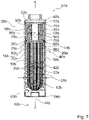
- the 7 shows another water treatment device.
- the embodiment of 7 differs from the previous exemplary embodiment at least essentially by an adsorption unit 18b of the water treatment device.
- the adsorption unit 18b is at least essentially tubular.
- the adsorption unit 18b has a tube wall 88b.
- the tube wall 88b defines a tube channel 90b.
- the water to be treated penetrates the adsorption unit 18b at least essentially perpendicularly to an axial direction 44b.
- the water is guided from a filter unit 10b in the axial direction 44b into the pipe channel 90b.
- the pipe channel 90b is closed at one end, so that the water penetrates the pipe wall 88b of the adsorption unit 18b at least essentially perpendicularly to the axial direction 44b. After the water the Has penetrated tube wall 88b, it enters an adsorption housing 34b. The adsorption housing 34b deflects the water in the axial direction 44b.
- the 8 shows an alternative water treatment device.
- the embodiment of 8 differs from the previous exemplary embodiments at least essentially in that a filter unit 10c of the water treatment device is of tubular design.
- the filter unit 10c has a tube wall 92c.
- the tube wall 92c is at least partially formed by a group 28c of filter elements 12c of the filter unit 10c.
- the filter elements 12c are arranged in a circle.
- a holding element 20c of the water treatment device, in which the filter elements 12c are arranged, is designed as a circular disc.
- the circular disc has an opening.
- the tube wall 92c defines a tube channel 94c.
- An adsorption housing 34c of the water treatment device is arranged within the pipe channel 94c.
- a filter housing 32c in which the filter unit 10c is at least partially arranged, is closed in the axial direction 44c. If water emerges from the filter elements 12c in the axial direction 44c in an operating state, it is deflected in the opposite direction by the filter housing 32c. The water enters the adsorption housing 34c through the opening of a holding element 20c, in particular in the axial direction 44c.
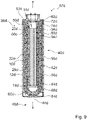
- the 9 shows another alternative water treatment device.
- the embodiment of 9 differs from the previous exemplary embodiments at least essentially in that an adsorption unit 18d of the water treatment device is upstream of a filter unit 10d of the water treatment device in terms of flow.
- the water treatment device has a flexible adsorption casing 96d instead of an adsorption housing.
- the adsorption casing 96d is designed in particular as a tubular sack.
- the adsorption liner 96d is formed of a cloth such as non-woven fabric.
- the adsorption unit 18d of the water treatment device is arranged inside the adsorption casing 96d.
- the adsorption casing 96d encloses a filter housing 32d of the water treatment device.
- the filter housing 32d is permeable to water perpendicular to an axial direction 44d.
- the filter housing 32d serves as a spacer between the filter unit 10d and the adsorption unit 18d.
- the filter unit 10d has a group 28d of filter elements 12d.
- the filter elements 12d are straight.
- the water treatment device has two holding elements 20d, 98d for end sections 14d, 16d of the filter elements 12d.
Landscapes
- Chemical & Material Sciences (AREA)
- Organic Chemistry (AREA)
- Engineering & Computer Science (AREA)
- Water Supply & Treatment (AREA)
- Life Sciences & Earth Sciences (AREA)
- Hydrology & Water Resources (AREA)
- Environmental & Geological Engineering (AREA)
- Chemical Kinetics & Catalysis (AREA)
- Inorganic Chemistry (AREA)
- Analytical Chemistry (AREA)
- Dispersion Chemistry (AREA)
- Geochemistry & Mineralogy (AREA)
- Clinical Laboratory Science (AREA)
- Health & Medical Sciences (AREA)
- Water Treatment By Sorption (AREA)
- Separation Using Semi-Permeable Membranes (AREA)
Description
- Die Erfindung betrifft eine Wasseraufbereitungsvorrichtung nach dem Oberbegriff von Anspruch 1.
- Es sind bereits Wasseraufbereitungsvorrichtungen vorgeschlagen worden, welche zur Aufbereitung von Wasser Filtereinheiten und Adsorptionseinheiten nutzen, um Schadstoffe aus Wasser zu entfernen. Während eine Aufbereitungseffizienz für die meisten im Wasser enthaltenen Schadstoffe ausreichend ist, ist die Aufbereitungseffizienz solcher Wasseraufbereitungsvorrichtungen in Bezug auf Mikroschadstoffe stark verringert, da diese zum einen in einer wesentlich geringeren Konzentration auftreten und zum andern zumindest im Wesentlichen kleinere Molekulargewichte aufweisen. Zwar liegen die Konzentrationen der einzelnen Mikroschadstoffe üblicherweise unterhalb der kritischen Verträglichkeitsgrenzwerte für Umwelt und Menschen, jedoch wird hierbei ein Summenparameter der verschiedenen Mikroschadstoffe nicht berücksichtigt. Daher ist es von großem Interesse, diese mit gesteigerter Effizienz aus Wasser zu entfernen.
- Die
EP 2 754 642 A1 offenbart eine Wasserreinigungskartusche, welche zwischen einem Rohwasserbehälter und einem Behälter für gereinigtes Wasser angeordnet ist. Die Wasserreinigungskartusche umfasst einen Behälter zur Aufnahme eines Adsorbers und eine Hohlfasermembran. Der Behälter umfasst einen Adsorberbereich, in welchem Adsorber angeordnet ist und welcher ein einen Wassersammelbereich aufweist, und einen Hohlfasermembranbereich, in welchem die Hohlfasermembran angeordnet ist und welche an einer Abströmseite des Adsorberbereichs angeordnet ist. - Aus der
EP 2 733 120 A1 ist eine Wasserreinigungskartusche bekannt, welche einen Behälter mit einer ersten Öffnung und einer zweiten Öffnung aufweist. Die Wasserreinigungskartusche umfasst ferner ein Filtermaterial, welches einen Adsorber und eine Hohlfasermembran umfasst. - Die
WO 03/089104 A2 - Aus der
JP 2012 030 204 A - Die Aufgabe der Erfindung besteht insbesondere darin, eine gattungsgemäße Vorrichtung mit verbesserten Eigenschaften hinsichtlich einer Effizienz, insbesondere einer Aufbereitungseffizienz, bereitzustellen. Die Aufgabe wird erfindungsgemäß durch die Merkmale des Anspruchs 1 gelöst, während vorteilhafte Ausgestaltungen und Weiterbildungen der Erfindung den Unteransprüchen entnommen werden können.
- Die Erfindung geht aus von einer Wasseraufbereitungsvorrichtung, welche zu einer Entfernung von Mikroschadstoffen, insbesondere Arzneimitteln, aus Wasser vorgesehen ist, mit zumindest einer Filtereinheit, welche in zumindest einem Betriebszustand wenigstens zu einer Filterung des Wassers vorgesehen ist und welche zumindest ein röhrenförmiges Filterelement mit zumindest zwei Endabschnitten aufweist, und mit zumindest einer Adsorptionseinheit, welche die Mikroschadstoffe in zumindest einem Betriebszustand zumindest teilweise adsorbiert.
- Die Endabschnitte schließen in einem montierten Zustand einen Innenwinkel von 0° bis 90° ein. Hierdurch kann eine Effizienz, insbesondere eine Aufbereitungseffizienz, verbessert werden. Insbesondere kann eine Durchflussrate bei einer Querstrom-Filtration verbessert werden.
- Unter "vorgesehen" soll insbesondere speziell ausgelegt und/oder ausgestattet verstanden werden. Darunter, dass ein Objekt zu einer bestimmten Funktion vorgesehen ist, soll insbesondere verstanden werden, dass das Objekt diese bestimmte Funktion in zumindest einem Anwendungs- und/oder Betriebszustand erfüllt und/oder ausführt. Unter einer "Wasseraufbereitungsvorrichtung" soll insbesondere eine Vorrichtung verstanden werden, welche dazu vorgesehen ist, Wasser, insbesondere Trinkwasser, aufzubereiten, zu läutern, zu klären, zu reinigen und/oder zu säubern und vorteilhaft Mikroschadstoffe zu entfernen, insbesondere indem diese aus dem Wasser gefiltert und/oder sorbiert, insbesondere absorbiert und/oder besonders bevorzugt adsorbiert werden. Die Wasseraufbereitungsvorrichtung ist insbesondere zumindest ein Teil, insbesondere eine Unterbaugruppe einer Wasseraufbereitungskartusche, eines Systems zur Wasseraufbereitung und/oder einer Wasseraufbereitungsanlage, wie beispielsweise einer Kläranlage. Insbesondere kann die Wasseraufbereitungsvorrichtung die Wasseraufbereitungskartusche, das System zur Wasseraufbereitung und/oder die Wasseraufbereitungsanlage vollständig umfassen. Insbesondere ist die Wasseraufbereitungsvorrichtung, vorteilhaft direkt, an einen Hauswasseranschluss, bevorzugt an einen Wasserhahn, anschließbar und ist diesem insbesondere strömungstechnisch vorgeschaltet. Unter einem "Betriebszustand" der Wasseraufbereitungsvorrichtung soll insbesondere ein Zustand verstanden werden, in welchem die Wasseraufbereitungsvorrichtung vollständig von Wasser durchflossen ist. Unter "Mikroschadstoffen" sollen insbesondere Schadstoffe wie beispielsweise Industriechemikalien, Arzneimittel, insbesondere Carbamazepin, Sulfamethoxazol, Diclofenac und/oder Ethinylestradiol, Schwermetalle und/oder Pestizide verstanden werden, welche im Wasser, insbesondere gelöst, in einer geringen Konzentration auftreten, und zwar insbesondere in einer Konzentration von weniger als 10000 ppm, bevorzugt von weniger als 1000 ppm, weiter bevorzugt von weniger als 100 ppm und besonders bevorzugt von weniger als 10 ppm. Insbesondere weisen die Mikroschadstoffe ein Molekulargewicht von weniger als 100 kDa, bevorzugt weniger als 10 kDa, weiter bevorzugt weniger als 1 kDa und besonders bevorzugt weniger als 0,1 kDa auf.
- Unter einer "Adsorptionseinheit" soll insbesondere eine Einheit mit zumindest einem Adsorptionselement verstanden werden, welches dazu vorgesehen ist, insbesondere mittels zumindest eines Adsorptionsmittels, vorzugsweise mehrerer Adsorptionsmittel, Mikroschadstoff, insbesondere gelösten Mikroschadstoff, zumindest im Wesentlichen fest zu binden und/oder zu adsorbieren, und zwar insbesondere an einer Oberfläche, vorzugsweise in einem Hohlraum und besonders bevorzugt in einer Pore des Adsorptionsmittels. Insbesondere ist der zugrunde liegende Adsorptionsmechanismus zur Bindung der Mikroschadstoffe von einer kovalenten Bindung verschieden. Vorteilhaft ist das Adsorptionselement dazu vorgesehen, die Mikroschadstoffe mittels Coulomb- und/oder van der Waals-Wechselwirkung zumindest im Wesentlichen fest zu binden. Darunter, "einen Mikroschadstoff zumindest im Wesentlichen fest zu binden", soll insbesondere verstanden werden, dass ein adsorbierter Mikroschadstoff bei einem Auswaschungstest mittels Durchspülen mit Wasser innerhalb eines Zeitraums von zumindest einer Stunde, vorteilhaft zumindest zwei Stunden und bevorzugt zumindest vier Stunden zu maximal einem Prozent, vorteilhaft maximal einem halben Prozent und bevorzugt maximal einem Promille einer gebundenen Stoffmenge ausgespült wird. Die Adsorptionseinheit ist insbesondere zumindest teilweise chemisch regenerierbar. Unter "chemisch regenerierbar" soll insbesondere verstanden werden, dass das zumindest eine Adsorptionsmittel durch eine chemische Reaktion regeneriert werden kann. Insbesondere ist das Adsorptionsmittel mittels einer Säure und/oder einer Lauge, vorzugsweise einer Natronlauge, chemisch regenerierbar. Ferner ist das Adsorptionsmittel insbesondere mittels einer Salzlösung, vorzugsweise einer Natriumchlorid-Lösung, chemisch regenerierbar. Alternativ oder zusätzlich ist das Adsorptionsmittel insbesondere durch Beaufschlagung mit Energie, wie beispielsweise in Form von Wärme und/oder elektromagnetischer Strahlung, insbesondere durch Licht, vorzugsweise UV-Licht, regenerierbar. Die Adsorptionseinheit ist insbesondere als ein vorteilhaft wasserdurchlässiger fester Block oder als eine Schüttung ausgebildet, welcher/welche zumindest teilweise von zumindest einem Adsorptionselement ausgebildet ist.
- Vorzugsweise weist die Adsorptionseinheit zumindest ein spezifisches und/oder unspezifisches Adsorptionselement auf. Unter einem "unspezifischen Adsorptionselement" soll insbesondere ein Adsorptionselement verstanden werden, welches zumindest ein unspezifisches Adsorptionsmittel aufweist, das dazu vorgesehen ist, mehrere verschiedene Mikroschadstoffe chemisch unspezifisch, insbesondere im gleichen Maße und vorzugsweise unabhängig von funktionellen Gruppen der Mikroschadstoffe und/oder einer Ladung der Mikroschadstoffe zu adsorbieren. Das unspezifische Adsorptionsmittel ist insbesondere dazu vorgesehen, verschiedene Mikroschadstoffe sterisch abhängig zu adsorbieren. Vorteilhaft kann das unspezifische Adsorptionselement mehrere unspezifische Adsorptionsmittel aufweisen. Unter einem "spezifischen Adsorptionselement" soll insbesondere ein Adsorptionselement verstanden werden, welches zumindest ein spezifisches Adsorptionsmittel aufweist, das dazu vorgesehen ist, bestimmte Mikroschadstoffe chemisch oder physikalisch spezifisch, insbesondere in unterschiedlichem Maße und vorzugsweise abhängig von funktionellen Gruppen der Mikroschadstoffe und/oder einer Ladung der Mikroschadstoffe zu adsorbieren. Das spezifische Adsorptionsmittel ist insbesondere dazu vorgesehen, bestimmte Mikroschadstoffe sterisch unabhängig zu adsorbieren. Vorteilhaft kann das spezifische Adsorptionselement mehrere spezifische Adsorptionsmittel aufweisen.
- Alternativ oder zusätzlich kann die Adsorptionseinheit zumindest teilweise einstückig mit einem weiteren Körper, wie beispielsweise der Filtereinheit, ausgebildet sein, und zwar vorteilhaft als Imprägnierung und/oder Beschichtung. Unter "zumindest teilweise einstückig ausgebildet" soll in diesem Zusammenhang insbesondere verstanden werden, dass zumindest ein Bauteil zumindest eines Objekts einstückig mit zumindest einem Bauteil zumindest eines weiteren Objekts ausgebildet ist. Unter "einstückig" soll insbesondere zumindest stoffschlüssig verbunden verstanden werden, beispielsweise durch einen Schweißprozess, einen Klebeprozess, einen Anspritzprozess und/oder einen anderen, dem Fachmann als sinnvoll erscheinenden Prozess. Vorteilhaft soll unter "einstückig" auch einteilig verstanden werden. Unter "einteilig" soll insbesondere in einem Stück geformt verstanden werden, wie beispielsweise durch eine Herstellung aus einem Guss und/oder durch eine Herstellung in einem Ein- oder Mehrkomponentenspritzverfahren, vorteilhaft aus einem einzelnen Rohling und besonders bevorzugt in einem Spinnverfahren, insbesondere einem Nassspinnverfahren, wie beispielsweise Reaktivspinnen, bei welchem insbesondere in einem Phaseninversionsprozess die Filtereinheit mit integriertem Adsorptionsmittel hergestellt wird, hergestellt.
- Unter einer "Filtereinheit" soll insbesondere eine Membranfiltereinheit verstanden werden, die dazu vorgesehen ist, Wasser von Mikroschadstoffen durch Zurückhaltung der Mikroschadstoffe an Poren der Filtermembran zu reinigen. Das Filterelement der Filtereinheit ist insbesondere als Filtermembran und vorteilhaft als eine Hohlfaserfiltermembran ausgebildet, bei welcher eine Wandung des Filterelements die Membran bildet und einen Hohlkanal definiert. Grundsätzlich kann das Filterelement eine Reinigung von in dem Hohlkanal geführtem Wasser bei einem Durchtritt aus dem geschlossenen Hohlkanal durch das Filterelement in einen Außenraum vornehmen, so dass aus dem Hohlkanal austretendes Wasser gereinigt wird, oder bevorzugt kann das Filterelement eine Reinigung von aus dem Außenraum in den Hohlkanal eintretendem Wasser vornehmen, welches dann im gereinigten Zustand in dem Hohlkanal geführt wird. Die Filtereinheit weist insbesondere zumindest ein Filterelement, vorzugsweise wenigstens 5 Filterelemente, bevorzugt wenigstens 10 und besonders bevorzugt mindestens 20 Filterelemente auf.
- Unter einem "Endabschnitt" eines Objekts soll insbesondere ein Abschnitt verstanden werden, welcher sich entlang einer Erstreckung, insbesondere einer Haupterstreckung, des Objekts bis zu einem Ende des Objekts erstreckt. Der Endabschnitt erstreckt sich entlang des Filterelements insbesondere über maximal 10 cm, vorzugsweise über maximal 5 cm und besonders bevorzugt über maximal 1 cm.
- Unter einem "Innenwinkel" soll insbesondere ein Winkel verstanden werden, welcher von zwei Vektoren eingeschlossen wird, welche parallel zu je einem Endabschnitt verlaufen und welche in Richtung eines eine Öffnung aufweisenden Endes des jeweiligen Endabschnitts zeigen.
- Insbesondere ist das Filterelement im montierten Zustand zumindest abschnittsweise gebogen und vorzugsweise schlingenförmig ausgebildet. Um eine besonders effiziente Anordnung des Filterelements zu erreichen und vorteilhaft einen Durchflussstrom zu erhöhen, ist das Filterelement im montierten Zustand im Wesentlichen u-förmig gebogen. Die zwei Endabschnitte des Filterelements sind im montierten Zustand insbesondere zumindest im Wesentlichen parallel, vorteilhaft antiparallel zueinander angeordnet. Das Filterelement weist vorzugsweise eine Haupterstreckungsebene auf, welche in dem montierten Zustand das Filterelement über die gesamte Erstreckung des Filterelements schneidet. Unter einer "Haupterstreckungsebene" eines Objekts soll insbesondere eine Ebene verstanden werden, welche parallel zu einer größten Seitenfläche eines kleinsten gedachten Quaders ist, welcher das Objekt gerade noch vollständig umschließt und durch den Mittelpunkt des Quaders verläuft. Unter "im Wesentlichen parallel" soll hier insbesondere eine Ausrichtung einer Richtung relativ zu einer Bezugsrichtung, insbesondere in einer Ebene, verstanden werden, wobei die Richtung gegenüber der Bezugsrichtung insbesondere eine Abweichung kleiner als 8°, vorteilhaft kleiner als 5° und besonders vorteilhaft kleiner als 2° aufweist.
- Es wird ferner vorgeschlagen, dass die Wasseraufbereitungsvorrichtung ein Halteelement aufweist, welches die Endabschnitte im montierten Zustand fest zueinander anordnet. Die zwei Endabschnitte des Filterelements sind im montierten Zustand insbesondere fest, vorzugsweise zumindest stoffschlüssig, mit dem Halteelement verbunden. Das Halteelement ist vorteilhaft von einem Bindemittel gebildet, wie beispielsweise einem Kleber, bevorzugt einem Harz, und besonders bevorzugt einem Epoxidharz. Das Filterelement, insbesondere die Endabschnitte des Filterelements, ist/sind, insbesondere zumindest teilweise, derart verödet, dass ein Eindringen des Bindemittels in das Filterelement, insbesondere in die Wandung des Filterelements, insbesondere an den Endabschnitten, vermieden wird. Bei einer Montage werden die Endabschnitte insbesondere in dem noch flüssigen Bindemittel angeordnet. Vorteilhaft wird das Bindemittel ausgehärtet. Ferner wird das ausgehärtete Bindemittel insbesondere derart angeschliffen, dass Öffnungen der Endabschnitte des Filterelements freiliegen. Das Halteelement ist vorzugsweise zylinderförmig, rohrförmig und/oder scheibenförmig ausgebildet. Hierdurch kann auf einfache Art und Weise das Filterelement fest angeordnet werden.
- Die Filtereinheit weist zumindest ein weiteres Filterelement auf, welches zumindest im Wesentlichen äquivalent zu dem Filterelement ausgebildet ist und welches das Filterelement zumindest teilweise umgreift. Darunter, dass "zwei Objekte zumindest im Wesentlichen äquivalent" sind, soll insbesondere verstanden werden, dass diese insbesondere im montierten Zustand weitgehend gleich ausgebildet sind, vorzugsweise gleiche Formgebung und insbesondere Orientierung aufweisen und sich vorzugsweise lediglich durch Produktionstoleranzen und/oder Fertigungsfehler voneinander unterscheiden. Insbesondere ist das weitere Filterelement auf ähnliche Weise geschlungen wie das Filterelement. Zusätzlich können sich die äquivalent ausgebildeten Filterelemente insbesondere durch eine Länge voneinander unterscheiden. Das Filterelement und das weitere Filterelement, insbesondere die Endabschnitte des Filterelements und die Endabschnitte des weiteren Filterelements, sind zueinander zumindest teilweise zumindest im Wesentlichen parallel oder vorzugsweise antiparallel angeordnet. Darunter, dass "ein weiteres Objekt ein Objekt zumindest teilweise umgreift", soll insbesondere verstanden werden, dass zumindest eine Gerade existiert, welche zunächst durch das weitere Objekt, danach durch das Objekt und anschließend wiederum durch das weitere Objekt verläuft. Ferner kann die Filtereinheit zusätzliche Filterelemente, insbesondere eine Vielzahl zusätzlicher Filterelemente, insbesondere zumindest im Wesentlichen äquivalent zu dem Filterelement ausgebildete zusätzliche Filterelemente, aufweisen, welche wiederum das Filterelement und das weitere Filterelement umgreifen. Alternativ kann das weitere Filterelement neben dem Filterelement angeordnet sein. Hierdurch kann insbesondere ein Bauraum verringert und vorteilhaft eine Packungsdichte der Filtereinheit verbessert werden.
- Erfindungsgemäß wird vorgeschlagen, dass das Filterelement im montierten Zustand eine Haupterstreckungsebene aufweist und das weitere Filterelement im montierten Zustand eine weitere Haupterstreckungsebene aufweist, welche verschieden von der Haupterstreckungsebene des Filterelements ist. Insbesondere kann die Haupterstreckungsebene des Filterelements zumindest im Wesentlichen parallel zu der weiteren Haupterstreckungsebene des weiteren Filterelements angeordnet sein. Hierdurch kann eine einfache Anordnung der Filterelemente erreicht werden. Die Haupterstreckungsebene des Filterelements und die weitere Haupterstreckungsebene des weiteren Filterelements sind zueinander winklig angeordnet. Flächennormalen der Haupterstreckungsebene des Filterelements und der weiteren Haupterstreckungsebene des weiteren Filterelements schließen einen Winkel von zumindest 20°, vorzugsweise von zumindest 50° und besonders bevorzugt von zumindest 80° und von höchstens 160°, vorzugsweise von höchstens 130° und besonders bevorzugt von höchstens 100° ein. Vorteilhaft sind die Haupterstreckungsebene des Filterelements und die weitere Haupterstreckungsebene des weiteren Filterelements zumindest im Wesentlichen senkrecht zueinander angeordnet. Der Ausdruck "zumindest im Wesentlichen senkrecht" soll hier insbesondere eine Ausrichtung einer Richtung relativ zu einer Bezugsrichtung definieren, wobei die Richtung und die Bezugsrichtung, insbesondere in einer Ebene betrachtet, einen Winkel von 90° einschließen und der Winkel insbesondere eine maximale Abweichung von 90° von insbesondere kleiner als 8°, vorteilhaft kleiner als 5° und besonders vorteilhaft kleiner als 2°, aufweist. Hierdurch kann ein homogener Durchfluss durch die Filterelemente erreicht werden.
- Um insbesondere eine Packungsdichte der Filtereinheit und vorteilhaft einen homogenen Durchfluss durch die Filterelemente weiter zu verbessern, weist die Filtereinheit eine Gruppe von Filterelementen und eine weitere Gruppe von weiteren Filterelementen auf. Die Gruppe von Filterelementen weist zumindest ein zusätzliches Filterelement, insbesondere mehrere zusätzliche Filterelemente, auf, welches/welche zumindest im Wesentlichen äquivalent zu dem Filterelement ausgebildet ist/sind. Die weitere Gruppe von weiteren Filterelementen weist zumindest ein zusätzliches weiteres Filterelement, insbesondere mehrere zusätzliche weitere Filterelemente, auf, welches/welche zumindest im Wesentlichen äquivalent zu dem weiteren Filterelement ausgebildet ist/sind. Die Filterelemente einer Gruppe sind mittels eines Netzes gebündelt. Jeweils eines der weiteren Filterelemente der weiteren Gruppe von weiteren Filterelementen umgreift zumindest jeweils zumindest eines der Filterelemente der Gruppe der Filterelemente. Jeweils eines der weiteren Filterelemente der weiteren Gruppe von weiteren Filterelementen weist zumindest vorzugsweise zumindest eine Haupterstreckungsebene auf, welche jeweils von zumindest einer Haupterstreckungsebene wenigstens eines Filterelements der Gruppe der Filterelemente verschieden ist. Alternativ oder zusätzlich kann die Filtereinheit nur eine der Gruppen oder zusätzliche Gruppen, insbesondere mit zusätzlichen Filterelementen, welche vorteilhaft das Filterelement und das weitere Filterelement umgreifen, aufweisen.
- Erfindungsgemäß wird vorgeschlagen, dass die Filtereinheit zumindest im Wesentlichen rohrförmig ausgebildet ist. Vorzugsweise sind Filterelemente der Filtereinheit kreisförmig angeordnet und bilden zumindest teilweise eine Rohrwandung der Filtereinheit. Die rohrförmige Filtereinheit definiert insbesondere einen Rohrkanal, in welchem vorteilhaft zumindest teilweise die Adsorptionseinheit angeordnet sein kann. Hierdurch kann ein Bauraum weiter reduziert werden.
- In einer weiter bevorzugten Ausgestaltung der Erfindung wird vorgeschlagen, dass die Adsorptionseinheit zumindest im Wesentlichen rohrförmig ausgebildet ist. Die rohrförmige Adsorptionseinheit definiert insbesondere einen Rohrkanal, in welchem vorteilhaft zumindest teilweise die Filtereinheit angeordnet sein kann. Hierdurch kann ein Bauraum weiter verringert werden.
- Um die Adsorptionseinheit vor Beschädigungen zu schützen, wird vorgeschlagen, dass die Wasseraufbereitungsvorrichtung ein Filtergehäuse aufweist, in welchem die Filtereinheit zumindest teilweise angeordnet ist. Das Filtergehäuse ist insbesondere als ein Hohlzylinder ausgebildet, welcher bevorzugt einen Zylindermantel aufweist, der die Filtereinheit teilweise umschließt. Die Filtereinheit ist insbesondere zu weniger als 80 %, vorzugsweise zu weniger als 60 % und besonders bevorzugt zu weniger als 40 % in dem Filtergehäuse angeordnet. Ferner umschließt der Zylindermantel insbesondere das Halteelement zumindest teilweise, vorzugsweise zumindest zu einem Großteil und besonders bevorzugt vollständig. Insbesondere ist das Halteelement stoffschlüssig mit dem Filtergehäuse verbunden.
- Um die Filtereinheit vor Beschädigungen zu schützen, wird vorgeschlagen, dass die Wasseraufbereitungsvorrichtung ein Adsorptionsgehäuse aufweist, in welchem die Adsorptionseinheit zumindest teilweise, insbesondere zu einem Großteil und vorzugsweise vollständig angeordnet ist. Das Adsorptionsgehäuse ist insbesondere als ein Hohlzylinder ausgebildet, welcher bevorzugt einen Zylindermantel aufweist, der die Adsorptionseinheit zumindest teilweise, insbesondere zumindest zu einem Großteil und bevorzugt vollständig umschließt. Unter dem Ausdruck "zumindest zu einem Großteil" sollen dabei insbesondere mehr als 50 %, vorteilhaft mehr als 65 %, vorzugsweise mehr als 75 %, besonders bevorzugt mehr als 85 % und besonders vorteilhaft zumindest 95 % verstanden werden. Hierdurch kann die Adsorptionseinheit vor Beschädigungen geschützt werden.
- Es wird des Weiteren vorgeschlagen, dass das Filtergehäuse dem Adsorptionsgehäuse strömungstechnisch vorgeschaltet ist. Insbesondere ist die in dem Filtergehäuse angeordnete Filtereinheit der in dem Adsorptionsgehäuse angeordneten Adsorptionseinheit strömungstechnisch vorgeschaltet. Hierdurch kann eine effiziente Anordnung und insbesondere daraus resultierende effiziente Durchströmung des Adsorptionsgehäuses erreicht werden.
- Denkbar ist insbesondere, dass das Filtergehäuse und das Adsorptionsgehäuse einstückig miteinander ausgebildet sind. Um eine Flexibilität der Wasseraufbereitungsvorrichtung und insbesondere eine Kundenfreundlichkeit zu erhöhen und um zu ermöglichen, dass einzelne Komponenten der Wasseraufbereitungsvorrichtung ausgetauscht werden könnten, wird vorgeschlagen, dass die Wasseraufbereitungsvorrichtung eine Verbindungseinheit aufweist, welche das Adsorptionsgehäuse und das Filtergehäuse im montierten Zustand miteinander verbindet. Die Verbindungseinheit ist insbesondere zu einer zumindest formschlüssigen Verbindung des Adsorptionsgehäuses und des Filtergehäuses vorgesehen. Alternativ oder zusätzlich kann die Verbindungseinheit auch zu einer kraft- und/oder stoffschlüssigen Verbindung vorgesehen sein. Die Verbindungseinheit ist insbesondere zumindest teilweise einstückig mit dem Adsorptionsgehäuse und/oder dem Filtergehäuse ausgebildet. Die Verbindungseinheit umfasst zumindest ein Verbindungselement, welches im montierten Zustand das Filtergehäuse mit dem Adsorptionsgehäuse verbindet. Das Verbindungselement ist insbesondere separat von dem Adsorptionsgehäuse und/oder dem Filtergehäuse ausgebildet. Vorzugsweise ist das Verbindungselement als eine vorzugsweise rohrförmige Muffe ausgebildet. Ferner weist die Verbindungseinheit zumindest eine Verbindungselementaufnahme auf, welche dazu vorgesehen ist, das Verbindungselement aufzunehmen. Die Verbindungselementaufnahme ist als eine Ausnehmung des Filtergehäuses und/oder des Adsorptionsgehäuses ausgebildet.
- Es wird ferner vorgeschlagen, dass die Wasseraufbereitungsvorrichtung zumindest eine Siebeinheit aufweist, welche das Filtergehäuse und das Adsorptionsgehäuse voneinander trennt und zumindest das Adsorptionsgehäuse von wenigstens einer Seite zumindest teilweise verschließt. Die Siebeinheit umfasst insbesondere zumindest einen Siebdeckel, welcher zumindest dazu vorgesehen ist, die Adsorptionseinheit von der Filtereinheit zu trennen. Der Siebdeckel weist insbesondere mehrere Durchlassöffnungen auf, um einen Durchfluss von Wasser zwischen Filtereinheit und Adsorptionseinheit zu ermöglichen. Der Siebdeckel ist insbesondere formschlüssig mit dem Adsorptionsgehäuse verbindbar. Alternativ oder zusätzlich kann der Siebdeckel einstückig mit dem Adsorptionsgehäuse ausgebildet sein. Ferner weist die Siebeinheit insbesondere zumindest eine, vorzugsweise poröse Fritte auf. Die Fritte ist insbesondere auf einer der Adsorptionseinheit zugewandten Seite der Siebeinheit angeordnet und ist vorzugsweise dazu vorgesehen, eine Verunreinigung der Adsorptionseinheit und besonders bevorzugt ein Austreten der Adsorptionseinheit aus dem Adsorptionsgehäuse zu vermeiden. Die Fritte ist insbesondere aus einem vorzugsweise vernetzten Kunststoff, insbesondere aus zumindest einem vernetzten Polymer, vorteilhaft Polyethylen, gebildet. Alternativ oder zusätzlich kann die Fritte zumindest teilweise einstückig mit der Adsorptionseinheit ausgebildet sein. Hierdurch kann insbesondere ein Schutz der empfindlichen Filtereinheit verbessert werden, da diese vor aus der Adsorptionseinheit austretenden Partikeln, insbesondere falls diese beschädigt ist, geschützt werden kann.
- Weiterhin wird vorgeschlagen, dass die Wasseraufbereitungsvorrichtung eine Kartusche aufweist, in welcher im montierten Zustand das Adsorptionsgehäuse und das Filtergehäuse angeordnet sind und welche Öffnungen aufweist, welche in axialer Richtung betrachtet in Umfangsrichtung zueinander versetzt angeordnet sind. Unter einer "axialen Richtung" soll insbesondere eine Haupterstreckungsrichtung und/oder vorzugsweise eine Drehsymmetrieachse der Kartusche, in welcher diese vorteilhaft zumindest eine dreizählige Drehsymmetrie aufweist, verstanden werden. Unter einer "Haupterstreckungsrichtung" eines Objekts soll dabei insbesondere eine Richtung verstanden werden, welche parallel zu einer längsten Kante eines kleinsten gedachten Quaders verläuft, welcher das Objekt gerade noch vollständig umschließt. Unter einer "Umfangsrichtung" soll insbesondere eine Richtung senkrecht zur Haupterstreckungsrichtung und/oder insbesondere eine Drehrichtung um die Drehsymmetrieachse der Kartusche verstanden werden. Insbesondere sind die Öffnungen in Umfangsrichtung um zumindest einen Großteil der Kartusche herum angeordnet. Die Öffnungen sind insbesondere zum Anströmen der Filtereinheit mit aufzubereitendem Wasser vorgesehen. Vorteilhaft weist die Kartusche weitere Öffnungen auf, welche entlang der axialen Richtung und insbesondere entlang der Umfangsrichtung versetzt zu den Öffnungen angeordnet sind. Die weiteren Öffnungen sind insbesondere zumindest im Wesentlichen äquivalent zu den Öffnungen ausgebildet. Die Kartusche ist insbesondere aus einem Kunststoff, vorzugsweise aus Polypropylen und besonders bevorzugt aus einem Polypropylen-Homopolymerisat ausgebildet. Hierdurch können insbesondere die in dem Filtergehäuse angeordnete Filtereinheit und die in dem Adsorptionsgehäuse angeordnete Adsorptionseinheit zusätzlich geschützt werden. Insbesondere kann die Filtereinheit besonders homogen von Wasser angeströmt werden.
- Die Wasseraufbereitungsvorrichtung soll hierbei nicht auf die oben beschriebene Anwendung und Ausführungsform beschränkt sein. Insbesondere kann die Wasseraufbereitungsvorrichtung zu einer Erfüllung einer hierin beschriebenen Funktionsweise eine von einer hierin genannten Anzahl von einzelnen Elementen, Bauteilen und Einheiten abweichende Anzahl aufweisen. Zudem sollen bei den in dieser Offenbarung angegebenen Wertebereichen auch innerhalb der genannten Grenzen liegende Werte als offenbart und als beliebig einsetzbar gelten.
- Weitere Vorteile ergeben sich aus der folgenden Zeichnungsbeschreibung. In den Zeichnungen sind Ausführungsbeispiele der Erfindung dargestellt. Die Zeichnungen, die Beschreibung und die Ansprüche enthalten zahlreiche Merkmale in Kombination. Der Fachmann wird die Merkmale zweckmäßigerweise auch einzeln betrachten und zu sinnvollen weiteren Kombinationen zusammenfassen.
- Es zeigen:
- Fig. 1
- eine Wasseraufbereitungskartusche mit einer Wasseraufbereitungsvorrichtung in einer Schnittansicht,
- Fig. 2
- eine Kartusche der Wasseraufbereitungsvorrichtung in einer Explosionsdarstellung,
- Fig. 3
- einen Teil der Wasseraufbereitungsvorrichtung in einer Explosionsdarstellung,
- Fig. 4
- einen Teil einer Filtereinheit der Wasseraufbereitungsvorrichtung in einer perspektivischen Darstellung,
- Fig. 5
- einen Teil einer Adsorptionseinheit der Wasseraufbereitungsvorrichtung in einer schematischen Schnittansicht,
- Fig. 6
- ein System mit einer Wasseraufbereitungsvorrichtung und einer Vorfiltrationseinheit in einer schematischen Schnittansicht,
- Fig. 7
- eine weitere Wasseraufbereitungsvorrichtung in einer Schnittansicht,
- Fig. 8
- eine alternative Wasseraufbereitungsvorrichtung in einer Schnittansicht und
- Fig. 9
- eine weitere alternative Wasseraufbereitungsvorrichtung in einer Schnittansicht.
-
Fig. 1 zeigt eine Wasseraufbereitungskartusche 57a mit einer Wasseraufbereitungsvorrichtung in einer Schnittansicht. Die Wasseraufbereitungsvorrichtung ist zu einer Entfernung von Mikroschadstoffen, insbesondere Arzneimitteln, aus Wasser, insbesondere Trinkwasser, vorgesehen. Hierzu ist die Wasseraufbereitungskartusche 57a zu einem Einbau in einem System zur Aufbereitung von Wasser vorgesehen. -
Fig. 2 zeigt eine Kartusche 40a der Wasseraufbereitungsvorrichtung. Die Kartusche 40a ist rohrförmig ausgebildet. Die Kartusche 40a weist einen Zylindermantel 58a auf. Der Zylindermantel 58a definiert in seinem Inneren einen Aufnahmeraum 60a. Der Aufnahmeraum 60a dient zur Aufnahme weiterer Einheiten der Wasseraufbereitungsvorrichtung. Die Kartusche 40a weist Öffnungen 42a auf, welche in axialer Richtung 44a betrachtet in Umfangsrichtung 46a zueinander versetzt angeordnet sind. Ferner sind die Öffnungen 42a in axial Richtung 44a zueinander versetzt angeordnet. Die Öffnungen 42a sind durch Ausnehmungen, insbesondere zur axialen Richtung 44a senkrechte Ausnehmungen, des Zylindermantels 58a gebildet. Die Kartusche 40a weist einen Kartuschenanschluss 62a auf. Der Kartuschenanschluss 62a ist zum Anschluss der Wasseraufbereitungsvorrichtung an eine Wasserleitung vorgesehen. Der Kartuschenanschluss 62a weist ein Schraubgewinde zum Anschluss der Wasseraufbereitungsvorrichtung auf. Der Kartuschenanschluss 62a verschließt den Zylindermantel 58a von einer Seite, insbesondere in axialer Richtung 44a. Ferner weist die Kartusche 40a einen Kartuschenabschluss 64a auf. Der Kartuschenabschluss 64a verschließt den Zylindermantel 58a von einer weiteren Seite, insbesondere in axialer Richtung 44a. Die Kartusche 40a ist aus einem Kunststoff ausgebildet. Vorteilhaft ist die Kartusche 40a aus Polypropylen und zwar besonders bevorzugt aus einem Polypropylen-Homopolymerisat (PP-H) ausgebildet. -
Fig. 3 zeigt eine Explosionsdarstellung eines Teils der Wasseraufbereitungsvorrichtung. Die Wasseraufbereitungsvorrichtung weist ein Filtergehäuse 32a auf. Das Filtergehäuse 32a ist im montierten Zustand in dem Aufnahmeraum 60a der Kartusche 40a angeordnet. In dem Filtergehäuse 32a ist zumindest teilweise eine Filtereinheit 10a der Wasseraufbereitungsvorrichtung angeordnet. Die Filtereinheit 10a ist in Haupterstreckungsrichtung der Filtereinheit 10a betrachtet zu weniger als 50 % innerhalb des Filtergehäuses 32a angeordnet. Das Filtergehäuse 32a ist als ein Hohlzylinder ausgebildet. Das Filtergehäuse 32a weist einen Zylindermantel auf, der ein Halteelement 20a der Wasseraufbereitungsvorrichtung zumindest teilweise umschließt. Ferner weist die Wasseraufbereitungsvorrichtung ein Adsorptionsgehäuse 34a auf. Das Adsorptionsgehäuse 34a ist im montierten Zustand in dem Aufnahmeraum 60a der Kartusche 40a angeordnet. In dem Adsorptionsgehäuse 34a ist eine Adsorptionseinheit 18a der Wasseraufbereitungsvorrichtung angeordnet. Das Adsorptionsgehäuse 34a ist als ein Hohlzylinder ausgebildet. Das Adsorptionsgehäuse 34a weist einen Zylindermantel auf, der die Adsorptionseinheit 18a zumindest teilweise umschließt. In einem Betriebszustand, in welchem die Wasseraufbereitungsvorrichtung von Wasser durchströmt ist, ist das Filtergehäuse 32a in Strömungsrichtung betrachtet dem Adsorptionsgehäuse 34a vorgeschaltet. - Die Wasseraufbereitungsvorrichtung weist eine Siebeinheit 38a auf. Die Siebeinheit 38a trennt das Filtergehäuse 32a und das Adsorptionsgehäuse 34a voneinander. Ferner verschließt die Siebeinheit 38a das Adsorptionsgehäuse 34a von wenigstens einer Seite zumindest teilweise. Die Siebeinheit 38a umfasst einen Siebdeckel 68a. Der Siebdeckel 68a verschließt die Adsorptionseinheit 18a von einer Seite zumindest teilweise. Ferner trennt der Siebdeckel 68a die Adsorptionseinheit 18a von der Filtereinheit 10a. Der Siebdeckel 68a ist formschlüssig mit dem Adsorptionsgehäuse 34a verbunden. Ferner könnte der Siebdeckel 68a kraft- und/oder stoffschlüssig mit dem Adsorptionsgehäuse 34a verbunden sein. Alternativ oder zusätzlich kann der Siebdeckel 68a einstückig mit dem Adsorptionsgehäuse 34a ausgebildet sein. Der Siebdeckel 68a weist mehrere Durchlassöffnungen auf. Die Durchlassöffnungen sind dazu vorgesehen, einen Wasserfluss zwischen der Filtereinheit 10a und der Adsorptionseinheit 18a zu ermöglichen.
- Die Siebeinheit 38a umfasst zumindest eine Fritte 70a. Die Fritte 70a ist scheibenförmig. Die Fritte 70a ist aus einem porösen Material hergestellt. Die Fritte 70a ist aus einem vernetzten Polyethylen hergestellt. Die Fritte 70a ist auf einer der Adsorptionseinheit 18a zugewandten Seite der Siebeinheit 38a angeordnet. Die Fritte 70a ist in dem Adsorptionsgehäuse 34a angeordnet. Die Fritte 70a ist in Durchflussrichtung betrachtet hinter dem Siebdeckel 68a und insbesondere vor der Adsorptionseinheit 18a angeordnet. Die Fritte 70a ist dazu vorgesehen, eine Verunreinigung der Adsorptionseinheit 18a und vorzugsweise ein zumindest teilweises Austreten der Adsorptionseinheit 18a aus dem Adsorptionsgehäuse 34a zu vermeiden.
- Die Siebeinheit 38a weist einen weiteren Siebdeckel 72a auf. Der weitere Siebdeckel 72a ist zumindest im Wesentlichen äquivalent zu dem Siebdeckel 68a ausgebildet. Der weitere Siebdeckel 72a ist einstückig mit dem Adsorptionsgehäuse 34a ausgebildet. Denkbar ist, dass der weitere Siebdeckel 72a separat von dem Adsorptionsgehäuse 34a ausgebildet und insbesondere kraft- und/oder formschlüssig mit diesem verbunden ist. Der weitere Siebdeckel 72a verschließt das Adsorptionsgehäuse 34a von wenigstens einer weiteren Seite zumindest teilweise. Der weiteren Siebdeckel 72a ist in Durchflussrichtung betrachtet hinter der Adsorptionseinheit 18a angeordnet. Ferner weist die Siebeinheit 38a eine weitere Fritte 74a auf. Die weitere Fritte 74a ist zumindest im Wesentlichen äquivalent zu der Fritte 70a ausgebildet. Die weitere Fritte 74a ist in dem Adsorptionsgehäuse 34a angeordnet. Die weitere Fritte 74a ist in Durchflussrichtung betrachtet hinter der Adsorptionseinheit 18a und insbesondere vor dem weiteren Siebdeckel 72a angeordnet.
- Die Wasseraufbereitungsvorrichtung weist eine Verbindungseinheit 36a auf. Die Verbindungseinheit 36a verbindet im montierten Zustand das Adsorptionsgehäuse 34a und das Filtergehäuse 32a, insbesondere formschlüssig, miteinander. Alternativ oder zusätzlich kann die Verbindungseinheit 36a auch zu einer kraft- und/oder stoffschlüssigen Verbindung vorgesehen sein. Es ist beispielsweise denkbar, dass die Verbindungseinheit 36a zu einer zusätzlichen kraftschlüssigen Verbindung ein Gewinde aufweist. Die Verbindungseinheit 36a umfasst zumindest ein Verbindungselement 76a, welches im montierten Zustand das Filtergehäuse 32a mit dem Adsorptionsgehäuse 34a verbindet. Das Verbindungselement 76a ist separat von dem Adsorptionsgehäuse 34a und/oder dem Filtergehäuse 32a ausgebildet. Alternativ oder zusätzlich kann das Verbindungselement 76a mit dem Filtergehäuse 32a und/oder dem Adsorptionsgehäuse 34a zumindest teilweise einstückig ausgebildet sein. Das Verbindungselement 76a ist als eine Muffe ausgebildet.
- Die Verbindungseinheit 36a weist zumindest eine Verbindungselementaufnahme 78a auf, welche dazu vorgesehen ist, das Verbindungselement 76a aufzunehmen. Die Verbindungselementaufnahme 78a ist korrespondierend zu dem Verbindungselement 76a ausgebildet. Die Verbindungselementaufnahme 78a ist als eine Ausnehmung des Adsorptionsgehäuses 34a ausgebildet. Die Verbindungseinheit 36a weist eine weitere Verbindungselementaufnahme 80a auf. Die weitere Verbindungselementaufnahme 80a ist zumindest im Wesentlichen äquivalent zu der Verbindungselementaufnahme 78a ausgebildet. Die weitere Verbindungselementaufnahme 80a ist als eine Ausnehmung des Filtergehäuses 32a ausgebildet.
- Bei einer Montage der Wasseraufbereitungsvorrichtung wird die weitere Fritte 74 a im Adsorptionsgehäuse 34a angeordnet. Ferner wird die Adsorptionseinheit 18a, insbesondere in Durchflussrichtung betrachtet hinter der weiteren Fritte 70a, in dem Adsorptionsgehäuse 34a angeordnet. Ferner wird die Fritte 70a, insbesondere in Durchflussrichtung betrachtet nach der Adsorptionseinheit 18a, in dem Adsorptionsgehäuse 34a angeordnet. Der Siebdeckel 68a verschließt das Adsorptionsgehäuse 34a. Die Filtereinheit 10a wird in dem Filtergehäuse 32a angeordnet. Das Filtergehäuse 32a wird in Durchflussrichtung betrachtet nach dem Adsorptionsgehäuse 34a angeordnet. Die Verbindungseinheit 36a verbindet das Adsorptionsgehäuse 34a und das Filtergehäuse 32a. Das Verbindungselement 76a greift in die Verbindungselementaufnahme 78a ein. Das Verbindungselement 76a greift in die weitere Verbindungselementaufnahme 80a ein. Das Filtergehäuse 32a und das Adsorptionsgehäuse 34 werden in dem Aufnahmeraum 60a der Kartusche 40a angeordnet. Der Zylindermantel 58a wird von dem Kartuschenabschluss 64a verschlossen. Ferner wird der Zylindermantel 58a mit dem Kartuschenanschluss 62a verbunden. Ferner kann die Kartusche 40a in einem übergeordneten Gehäuse 82a angeordnet werden (vgl.
Fig. 6 ). - In
Fig. 4 ist schematisch ein Teil der Filtereinheit 10a dargestellt. Die Filtereinheit 10a ist in einem Betriebszustand der Wasseraufbereitungsvorrichtung wenigstens zu einer Filterung des Wassers vorgesehen. Die Filtereinheit 10a ist als eine Membranfiltereinheit ausgebildet. Die Filtereinheit 10a weist zumindest ein Filterelement 12a auf. Die Filtereinheit 10a weist insbesondere eine Vielzahl von Filterelementen 12a, 22a auf, wobei inFig. 4 der Übersichtlichkeit halber nur zwei zueinander äquivalente Filterelemente 12a, 22a dargestellt sind. Das Filterelement 12a ist röhrenförmig. Das Filterelement 12a ist als eine Filtermembran ausgebildet. Bei der Filtermembran handelt es sich um eine Hohlfaserfiltermembran. Das Filterelement 12a weist eine Wandung auf. Die Wandung bildet die Filtermembran. Die Wandung definiert einen Hohlkanal des Filterelements 12a. Das Filterelement 12a weist einen ersten Endabschnitt 14a und einen zweiten Endabschnitt 16a auf. Die Endabschnitte 14a, 16a erstrecken sich entlang des Filterelements 12 über maximal 5 cm. Die Endabschnitte 14a, 16a sind mittels des Halteelements 20a der Wasseraufbereitungsvorrichtung fest zueinander angeordnet. Die Endabschnitte 14a, 16a des Filterelements 12a sind fest mit dem Halteelement 20a verbunden. Das Halteelement 20a ist als ein scheibenförmiger Block ausgebildet. Das Halteelement 20a ist stoffschlüssig mit dem Filtergehäuse 32a verbunden. Das Halteelement 20a ist vorteilhaft aus einem Bindemittel 86a gebildet. Das Bindemittel 86a ist ein Epoxidharz. Denkbar ist, dass ein anderes Bindemittel 86a verwendet werden kann, wie beispielsweise ein Kleber und/oder ein Kunststoff. Die Endabschnitte 14a, 16a werden vor einer Montage des Filterelements 12a derart verödet, dass das Bindemittel 86a nicht das Filterelement 12a, insbesondere die Wandung des Filterelements 12a, verunreinigt. Bei einer Montage wird das Filtergehäuse 32a mit dem Bindemittel 86a gefüllt. Die Endabschnitte 14a, 16a des Filterelements 12a werden in dem noch flüssigen Bindemittel 86a angeordnet. Das Bindemittel 86a wird zum Halteelement 20a ausgehärtet. Ferner wird das ausgehärtete Bindemittel 86a derart angeschliffen, dass Öffnungen der Endabschnitte 14a, 16a des Filterelements 12a freiliegen. - Das Filterelement 12a ist im montierten Zustand zumindest abschnittsweise gebogen und weist insbesondere eine Schlingenform auf. Das Filterelement 12a ist derart gebogen, dass die Endabschnitte 14a, 16a des Filterelements 12a einen Innenwinkel von 0° bis 90° einschließen. Im vorliegenden Fall sind die Endabschnitte 14a, 16a zumindest im Wesentlichen parallel oder vorzugsweise antiparallel zueinander, so dass das Filterelement 12a vorzugsweisen u-förmig gebogen ist. Im vorliegenden Fall beträgt der Innenwinkel demzufolge ungefähr 0°. Das Filterelement 12a weist insbesondere eine Haupterstreckungsebene 24a auf. Das Filterelement 12a ist über die gesamte Erstreckung des Filterelements 12a von der Haupterstreckungsebene 24a geschnitten.
- Ferner weist die Filtereinheit 10a zumindest ein weiteres Filterelement 22a auf. Das weitere Filterelement 22a ist zumindest im Wesentlichen äquivalent zu dem Filterelement 12a ausgebildet, insbesondere äquivalent zu diesem geformt und vorteilhaft äquivalent mit dem Halteelement 20a befestigt. Das Filterelement 12a und das weitere Filterelement 22a unterscheiden sich voneinander durch eine Länge. Das weitere Filterelement 22a umgreift das Filterelement 12a zumindest teilweise. Das weitere Filterelement 22a weist eine weitere Haupterstreckungsebene 26a auf. Im montierten Zustand ist die weitere Haupterstreckungsebene 26a des weiteren Filterelements 22a verschieden von der Haupterstreckungsebene 24a des Filterelements 12a. Ferner sind die Haupterstreckungsebene 24a des Filterelements 12a und die weitere Haupterstreckungsebene 26a des weiteren Filterelements 22a zueinander winklig angeordnet. Im vorliegenden Fall sind die Haupterstreckungsebene 24a des Filterelements 12a und die weitere Haupterstreckungsebene 26a des weiteren Filterelements 22a zumindest im Wesentlichen senkrecht zueinander. Ferner können die Haupterstreckungsebenen 24a, 26a auch einen anderen Winkel zueinander aufweisen, insbesondere von 20° bis 160°, oder alternativ zumindest im Wesentlichen parallel zueinander angeordnet sein.
- Die Filtereinheit 10a weist ferner eine Gruppe 28a (vgl.
Fig. 2 ) von Filterelementen 12a auf. Die Gruppe 28a von Filterelementen 12a weist zumindest ein zusätzliches Filterelement 12a, insbesondere mehrere zusätzliche Filterelemente 12a auf, welches/welche zumindest im Wesentlichen äquivalent zu dem Filterelement 12a ausgebildet ist/sind. Die Filterelemente 12a der Gruppe 28a sind insbesondere mittels eines Netzes des Wasseraufbereitungsvorrichtung gebündelt. Die Filtereinheit 10a weist ferner eine weitere Gruppe 30a (vgl.Fig. 2 ) von weiteren Filterelementen 22a auf. Die weitere Gruppe 30a von weiteren Filterelementen 22a weist zumindest ein zusätzliches weiteres Filterelement 22a, insbesondere mehrere zusätzliche weitere Filterelemente 22a auf, welches/welche zumindest im Wesentlichen äquivalent zu dem weiteren Filterelement 22a ist/sind. Die Filterelemente 22a der Gruppe 30a sind insbesondere mittels eines weiteren Netzes des Wasseraufbereitungsvorrichtung gebündelt. Alternativ oder zusätzlich kann die Filtereinheit 10a nur eine der Gruppen 28a, 30a oder zusätzliche Gruppen aufweisen. - In
Fig. 5 ist die Adsorptionseinheit 18a schematisch in einer Schnittansicht dargestellt. Die Adsorptionseinheit 18a weist ein unspezifisches Adsorptionselement 50a auf. Die Adsorptionseinheit 18a kann zu mindestens 10 % und zu höchstens 98 % aus dem unspezifischen Adsorptionselement 50a bestehen. Im vorliegenden Fall besteht die Adsorptionseinheit 18a zu 80 % aus dem unspezifischen Adsorptionselement 50a. Insbesondere kann die Adsorptionseinheit 18a auch zu weiteren Werten von 10 % bis 98 % aus dem unspezifischen Adsorptionselement 50a bestehen. - Das unspezifische Adsorptionselement 50a umfasst zumindest ein organisches Adsorptionsmittel. Im vorliegenden Fall ist das organische Adsorptionsmittel Aktivkohle. Das organische Adsorptionsmittel liegt dabei in Form einer zylinderförmigen Blocks vor. Das organische Adsorptionsmittel ist Aktivkohle, insbesondere gesinterten granulierte Aktivkohle. Alternativ oder zusätzlich kann das organische Adsorptionsmittel als Schüttung, insbesondere in granulierter Form vorliegen. Das unspezifische Adsorptionselement 50a umfasst einen Grundkörper 54a. Der Grundkörper 54a bildet zu einem Großteil die Adsorptionseinheit 18a aus. Die Adsorptionseinheit 18a weist ein Adsorptionsmittel auf, welches den Grundkörper 54a der Adsorptionseinheit 18a zumindest teilweise ausbildet. Im vorliegenden Fall bildet das organische Adsorptionsmittel den Grundkörper 54a zumindest teilweise aus. Alternativ kann das organische Adsorptionsmittel den Grundkörper 54a vollständig ausbilden.
- Ferner umfasst das unspezifische Adsorptionselement 50a zumindest ein mineralisches Adsorptionsmittel. Das unspezifische Adsorptionselement 50a weist zu 5 % bis 20 % zumindest das eine mineralische Adsorptionsmittel auf. Im vorliegenden Fall weist das unspezifische Adsorptionselement 50a zu 5 % ein mineralisches Adsorptionsmittel auf. Im vorliegenden Fall ist das mineralische Adsorptionsmittel Bentonit. Ferner bildet das mineralische Adsorptionsmittel zumindest teilweise den Grundkörper 54a des unspezifischen Adsorptionselements 50a aus. Alternativ oder zusätzlich kann das unspezifische Adsorptionselement 50a als mineralisches Adsorptionsmittel Kieselgur, Kieselgel, Aluminiumoxid und/oder Zinkoxid aufweisen.
- Die Adsorptionseinheit 18a weist ein spezifisches Adsorptionselement 52a auf. Die Adsorptionseinheit 18a kann zu mindestens 2 % und zu höchstens 90 % aus dem spezifischen Adsorptionselement 52a bestehen. Im vorliegenden Fall besteht die Adsorptionseinheit 18a zu 20 % aus dem spezifischen Adsorptionselement 52a. Insbesondere kann die Adsorptionseinheit 18a auch zu weiteren Werten von 2 % bis 90 % aus dem spezifischen Adsorptionselement 52a bestehen. Das spezifische Adsorptionselement 52a umfasst zumindest ein spezifisches Adsorptionsmittel. Alternativ oder zusätzlich kann der Grundkörper 54a der Adsorptionseinheit 18a zumindest teilweise aus einem spezifischen Adsorptionsmittel gebildet sein.
- Das spezifische Adsorptionselement 52a umfasst zumindest ein Umkehrphasen-Adsorptionsmittel, wie beispielsweise ein quervernetztes, funktionalisiertes organisches Polymer. Vorzugsweise umfasst das spezifische Adsorptionselement 52a als Umkehrphasen-Adsorptionsmittel quervernetztes Ethylvinylbenzol. Ferner umfasst das spezifische Adsorptionselement 52a zumindest ein lonentauscher-Adsorptionsmittel. Das lonentauscher-Adsorptionsmittel kann als Kationentauscher oder Anionentauscher ausgebildet sein. Im vorliegenden Fall ist das lonentauscher-Adsorptionsmittel als ein Anionentauscher ausgebildet. Das lonentauscher-Adsorptionsmittel ist eine Agarose, welche mittels einer Ammoniumgruppe, vorzugsweise einer quaternären Ammoniumgruppe und besonders bevorzugt Diethylaminoethyl (DEAE), funktionalisiert ist. Ferner umfasst das spezifische Adsorptionselement 52a zumindest ein Adsorptionsmittel, welches zu einer Adsorption über Wasserstoffbrücken vorgesehen ist. Im vorliegenden Fall ist das Adsorptionsmittel, welches zu einer Adsorption über Wasserstoffbrücken vorgesehen ist, lineares und/oder quervernetztes Polyvinylpyrrolidon (PVPP). Ferner umfasst das spezifische Adsorptionselement 52a zumindest ein Komplexbildner-Adsorptionsmittel. Im vorliegenden Fall ist das Komplexbildner-Adsorptionsmittel Ethylendiamintetraessigsäure (EDTA). Alternativ oder zusätzlich kann das spezifische Adsorptionselement 52a weitere spezifische Adsorptionsmittel aufweisen.
- Das unspezifische Adsorptionselement 50a und das spezifische Adsorptionselement 52a stehen zumindest teilweise miteinander in Kontakt. Das unspezifische Adsorptionselement 50a und das spezifische Adsorptionselement 52a sind zumindest teilweise ineinander angeordnet und insbesondere miteinander vermischt.
- In einem Betriebszustand ist die Wasseraufbereitungsvorrichtung vollständig mit aufzubereitendem Wasser durchflossen (vgl.
Fig. 1 ). Die Richtung, in welcher das Wasser in die Wasseraufbereitungsvorrichtung eintritt, ist insbesondere zumindest im Wesentlichen senkrecht zu einer Richtung, in welcher das Wasser die Wasseraufbereitungsvorrichtung verlässt. Das Wasser tritt durch die Öffnungen der Kartusche 40a, insbesondere zumindest im Wesentlichen senkrecht zur axialen Richtung 44a, in die Wasseraufbereitungsvorrichtung ein. Ferner dringt das Wasser zumindest im Wesentlichen senkrecht zur axialen Richtung 44a in die Filtereinheit 10a ein. Das Wasser durchdringt das Filterelement 12a, insbesondere die Wandung des Filterelements 12a, zumindest teilweise. Das Wasser wird mittels der Wandung gefiltert. Das Wasser sammelt sich im Inneren des Filterelements 12a, insbesondere im Hohlkanal. Der Hohlkanal leitet das Wasser in Richtung der Adsorptionseinheit 18a. Das Wasser durchdringt die Adsorptionseinheit 18a, insbesondere in axialer Richtung 44a. Im Wasser enthaltene Mikroschadstoffe werden von der Adsorptionseinheit 18a adsorbiert. Das Wasser verlässt die Wasseraufbereitungsvorrichtung durch den Kartuschenanschluss 62a, insbesondere in axialer Richtung 44a. - In
Fig. 6 ist ein System mit der Wasseraufbereitungsvorrichtung und mit einer Vorfiltrationseinheit 56a gezeigt. Die Vorfiltrationseinheit 56a ist der Wasseraufbereitungsvorrichtung strömungstechnisch vorgeschaltet. Das System ist zu einem Einbau in eine Wasserleitung vorgesehen. Die Vorfiltrationseinheit 56a ist als Mikrofiltrationseinheit mit einer Filtermembran ausgebildet und zu einer Rückhaltung von groben Schmutzpartikeln mit einer Größe von zumindest 5 µm vorgesehen. In alternativen Ausgestaltungen können Filtermembranen verwendet werden, die für eine Zurückhaltung von groben Schmutzpartikeln mit anderen Größen, beispielsweise 20 µm, geeignet sind. In der Wasseraufbereitungsvorrichtung werden anschließend die Mikroschadstoffe entfernt. - Die Wasseraufbereitungsvorrichtung ist in dem übergeordneten Gehäuse 82a angeordnet. Das übergeordnete Gehäuse 82a weist einen Ablauf mit Schraubgewinde für einen Anschluss an eine Wasserleitung auf. Die Vorfiltrationseinheit 56a ist in einem weiteren übergeordneten Gehäuse 84a angeordnet. Das weitere übergeordnete Gehäuse 84a weist einen Anschluss mit Schraubgewinde für einen Anschluss an eine Wasserleitung auf. Die Vorfiltrationseinheit 56a und die Wasseraufbereitungsvorrichtung sind so zueinander angeordnet, dass Wasser, welches in das weitere übergeordnete Gehäuse 84a eintritt, zunächst die Vorfiltrationseinheit 56a passiert und anschließend in das übergeordnete Gehäuse 82a gelangt, in welchem das Wasser mittels der Wasseraufbereitungsvorrichtung aufbereitet wird.
- In den
Fig. 7 bis 9 sind weitere Ausführungsbeispiele der Erfindung gezeigt. Die nachfolgenden Beschreibungen und die Zeichnungen beschränken sich im Wesentlichen auf die Unterschiede zwischen den Ausführungsbeispielen, wobei bezüglich gleich bezeichneter Bauteile, insbesondere in Bezug auf Bauteile mit gleichen Bezugszeichen, grundsätzlich auch auf die Zeichnungen und/oder die Beschreibung der anderen Ausführungsbeispiele, insbesondere derFig. 1 bis 6 , verwiesen werden kann. Zur Unterscheidung der Ausführungsbeispiele ist der Buchstabe a den Bezugszeichen des Ausführungsbeispiels in denFig. 1 bis 6 nachgestellt. In den Ausführungsbeispielen derFig. 7 bis 9 ist der Buchstabe a durch die Buchstaben b bis d ersetzt. - Die
Fig. 7 zeigt eine weitere Wasseraufbereitungsvorrichtung. Das Ausführungsbeispiel derFig. 7 unterscheidet sich von dem vorherigen Ausführungsbeispiel zumindest im Wesentlichen durch eine Adsorptionseinheit 18b der Wasseraufbereitungsvorrichtung. Im vorliegenden Fall ist die Adsorptionseinheit 18b zumindest im Wesentlichen rohrförmig ausgebildet. Die Adsorptionseinheit 18b weist eine Rohrwandung 88b auf. Die Rohrwandung 88b definiert einen Rohrkanal 90b. Im Betriebszustand durchdringt das aufzubereitende Wasser die Adsorptionseinheit 18b zumindest im Wesentlichen senkrecht zu einer axialen Richtung 44b. Das Wasser wird von einer Filtereinheit 10b in axialer Richtung 44b in den Rohrkanal 90b geführt. Der Rohrkanal 90b ist an einem Ende verschlossen, so dass das Wasser zumindest im Wesentlichen senkrecht zur axialen Richtung 44b die Rohrwandung 88b der Adsorptionseinheit 18b durchdringt. Nachdem das Wasser die Rohrwandung 88b durchdrungen hat, tritt es in ein Adsorptionsgehäuse 34b ein. Das Adsorptionsgehäuse 34b lenkt das Wasser in die axiale Richtung 44b um. - Die
Fig. 8 zeigt eine alternative Wasseraufbereitungsvorrichtung. Das Ausführungsbeispiel derFig. 8 unterscheidet sich von den vorherigen Ausführungsbeispielen zumindest im Wesentlichen dadurch, dass eine Filtereinheit 10c der Wasseraufbereitungsvorrichtung rohrförmig ausgebildet ist. Die Filtereinheit 10c weist eine Rohrwandung 92c auf. Die Rohrwandung 92c ist zumindest teilweise gebildet durch eine Gruppe 28c von Filterelementen 12c der Filtereinheit 10c. Die Filterelemente 12c sind in einem Kreis angeordnet. Ein Halteelement 20c der Wasseraufbereitungsvorrichtung, in welcher die Filterelemente 12c angeordnet sind, ist als eine Kreisscheibe ausgebildet. Die Kreisscheibe weist eine Öffnung auf. Die Rohrwandung 92c definiert einen Rohrkanal 94c. Ein Adsorptionsgehäuse 34c der Wasseraufbereitungsvorrichtung ist innerhalb des Rohrkanals 94c angeordnet. Ein Filtergehäuse 32c, in welchem die Filtereinheit 10c zumindest teilweise angeordnet ist, ist in axialer Richtung 44c verschlossen. Tritt Wasser in einem Betriebszustand aus den Filterelementen 12c in axialer Richtung 44c aus, wird es von dem Filtergehäuse 32c in umgekehrte Richtung umgelenkt. Das Wasser tritt durch die Öffnung eines Halteelements 20c in das Adsorptionsgehäuse 34c ein, insbesondere in axialer Richtung 44c. - Die
Fig. 9 zeigt eine weitere alternative Wasseraufbereitungsvorrichtung. Das Ausführungsbeispiel derFig. 9 unterscheidet sich von den vorherigen Ausführungsbeispielen zumindest im Wesentlichen dadurch, dass eine Adsorptionseinheit 18d der Wasseraufbereitungsvorrichtung einer Filtereinheit 10d der Wasseraufbereitungsvorrichtung strömungstechnisch vorgeschaltet ist. Im vorliegenden Fall weist die Wasseraufbereitungsvorrichtung anstelle eines Adsorptionsgehäuses eine flexible Adsorptionsummantelung 96d auf. Die Adsorptionsummantelung 96d ist insbesondere als ein schlauchförmiger Sack ausgebildet. Die Adsorptionsummantelung 96d ist aus einem Stoff gebildet, wie beispielsweise einem Vlies. Die Adsorptionseinheit 18d der Wasseraufbereitungsvorrichtung ist innerhalb der Adsorptionsummantelung 96d angeordnet. Ferner umgreift im vorliegenden Fall die Adsorptionsummantelung 96d ein Filtergehäuse 32d der Wasseraufbereitungsvorrichtung. Das Filtergehäuse 32d ist im vorliegenden Fall senkrecht zu einer axialen Richtung 44d wasserdurchlässig. Das Filtergehäuse 32d dient als Abstandshalter zwischen der Filtereinheit 10d und der Adsorptionseinheit 18d. Die Filtereinheit 10d weist eine Gruppe 28d von Filterelementen 12d auf. Die Filterelemente 12d sind gerade. Im vorliegenden Fall weist die Wasseraufbereitungsvorrichtung zwei Halteelemente 20d, 98d für Endabschnitte 14d, 16d der Filterelemente 12d auf.
Claims (10)
- Wasseraufbereitungsvorrichtung, welche zu einer Entfernung von Mikroschadstoffen, insbesondere Arzneimitteln, aus Wasser vorgesehen ist, mit einer Filtereinheit (10a - 10c), welche in einem Betriebszustand zu einer Filterung des Wassers vorgesehen ist und welche ein röhrenförmiges Filterelement (12a - 12c) mit zwei Endabschnitten (14a - 14c, 16a - 16c) aufweist, und mit einer Adsorptionseinheit (18a - 18c), welche die Mikroschadstoffe in einem Betriebszustand zumindest teilweise adsorbiert, wobei die Endabschnitte (14a - 14c, 16a - 16c) in einem montierten Zustand einen Innenwinkel von 0° bis 90° einschließen, wobei das Filterelement (12a - 12c) im montierten Zustand im Wesentlichen u-förmig gebogen ist, wobei die Filtereinheit (10a; 10b) zumindest ein weiteres Filterelement (22a; 22b) aufweist, welches im Wesentlichen äquivalent zu dem Filterelement (12a; 12b) ausgebildet ist dadurch gekennzeichnet, dass Flächennormalen der Haupterstreckungsebene (24a) des Filterelements (12a; 12b) und Flächennormalen der Haupterstreckungsebene (26a) des weiteren Filterelements (22a; 22b) einen Winkel von zumindest 20° und höchstens 160° einschließen, dass das weitere Filterelement (22a;22b) das Filterelement (12a; 12b) zumindest teilweise umgreift, dass die Filtereinheit (10a; 10b) eine Gruppe (28a; 28b) von Filterelementen (12a; 12b) und eine weitere Gruppe (30a; 30b) von weiteren Filterelementen (22a; 22b) aufweist, wobei die Gruppe von Filterelementen zumindest ein zusätzliches Filterelement aufweist, welches im Wesentlichen äquivalent zu dem Filterelement (12a; 12b) ausgebildet ist, wobei die weitere Gruppe von weiteren Filterelementen (22a; 22b) zusätzlich mindestens ein weiteres Filterelement aufweist, welches im Wesentlichen äquivalent zu dem weiteren Filterelement ausgebildet ist, wobei die Filterelemente der einen Gruppe mittels eines Netzes gebündelt sind und wobei die weiteren Filterelemente (22a; 22b) der weiteren Gruppe (30a; 30b) mittels eines weiteren Netzes gebündelt sind,
dass das Filterelement (12a; 12b) im montierten Zustand eine Haupterstreckungsebene (24a) aufweist und dass das weitere Filterelement (22a; 22b) im montierten Zustand eine weitere Haupterstreckungsebene (26a) aufweist, welche verschieden von der Haupterstreckungsebene (24a) des Filterelements (12a; 12b) ist, wobei die Haupterstreckungsebene (24a) des Filterelements (12a; 12b) und die weitere Haupterstreckungsebene (26a) des weiteren Filterelements (22a; 22b) zueinander winklig angeordnet sind. - Wasseraufbereitungsvorrichtung nach Anspruch 1, gekennzeichnet durch ein Halteelement (20a - 20d), welches die Endabschnitte (14a - 14d, 16a - 16d) im montierten Zustand fest zueinander anordnet.
- Wasseraufbereitungsvorrichtung nach einem der vorhergehenden Ansprüche, dadurch gekennzeichnet, dass die Filtereinheit (10c) im Wesentlichen rohrförmig ausgebildet ist.
- Wasseraufbereitungsvorrichtung nach einem der vorhergehenden Ansprüche, dadurch gekennzeichnet, dass die Adsorptionseinheit (18d) im Wesentlichen rohrförmig ausgebildet ist.
- Wasseraufbereitungsvorrichtung nach einem der vorhergehenden Ansprüche, gekennzeichnet durch ein Filtergehäuse (32a - 32d), in welchem die Filtereinheit (10a - 10d) zumindest teilweise angeordnet ist.
- Wasseraufbereitungsvorrichtung nach einem der vorhergehenden Ansprüche, gekennzeichnet durch ein Adsorptionsgehäuse (34a - 34c), in welchem die Adsorptionseinheit (18a - 18c) zumindest teilweise angeordnet ist.
- Wasseraufbereitungsvorrichtung nach den Ansprüchen 5 und 6,
dadurch gekennzeichnet, dass das Filtergehäuse (32a - 32c) dem Adsorptionsgehäuse (34a - 34c) strömungstechnisch vorgeschaltet ist. - Wasseraufbereitungsvorrichtung nach einem der Ansprüche 5 bis 7, gekennzeichnet durch eine Verbindungseinheit (36a - 36c), welche das Adsorptionsgehäuse (34a - 34c) und das Filtergehäuse (32a - 32c) im montierten Zustand miteinander verbindet.
- Wasseraufbereitungsvorrichtung nach einem der Ansprüche 5 bis 8, gekennzeichnet durch zumindest eine Siebeinheit (38a - 38c), welche das Filtergehäuse (32a - 32c) und das Adsorptionsgehäuse (34a - 34c) voneinander trennt und das Adsorptionsgehäuse (34a - 34c) von wenigstens einer Seite zumindest teilweise verschließt.
- Wasseraufbereitungsvorrichtung nach einem der Ansprüche 5 bis 9, gekennzeichnet durch eine Kartusche (40a - 40d), in welcher im montierten Zustand das Adsorptionsgehäuse (34a - 34d) und das Filtergehäuse (32a - 32d) angeordnet sind und welche Öffnungen (42a - 42d) aufweist, die in axialer Richtung (44a - 44d) betrachtet in Umfangsrichtung (46a - 46d) zueinander versetzt angeordnet sind.
Applications Claiming Priority (2)
| Application Number | Priority Date | Filing Date | Title |
|---|---|---|---|
| DE102016107483.7A DE102016107483A1 (de) | 2016-04-22 | 2016-04-22 | Wasseraufbereitungsvorrichtung |
| PCT/EP2017/059553 WO2017182653A1 (de) | 2016-04-22 | 2017-04-21 | Wasseraufbereitungsvorrichtung |
Publications (2)
| Publication Number | Publication Date |
|---|---|
| EP3445719A1 EP3445719A1 (de) | 2019-02-27 |
| EP3445719B1 true EP3445719B1 (de) | 2022-04-20 |
Family
ID=58671593
Family Applications (1)
| Application Number | Title | Priority Date | Filing Date |
|---|---|---|---|
| EP17721562.1A Active EP3445719B1 (de) | 2016-04-22 | 2017-04-21 | Wasseraufbereitungsvorrichtung |
Country Status (10)
| Country | Link |
|---|---|
| US (1) | US10961128B2 (de) |
| EP (1) | EP3445719B1 (de) |
| JP (1) | JP6957834B2 (de) |
| KR (1) | KR102414538B1 (de) |
| CN (1) | CN109071268B (de) |
| AU (1) | AU2017253495B2 (de) |
| DE (1) | DE102016107483A1 (de) |
| NZ (1) | NZ747675A (de) |
| SG (1) | SG11201808667QA (de) |
| WO (1) | WO2017182653A1 (de) |
Families Citing this family (7)
| Publication number | Priority date | Publication date | Assignee | Title |
|---|---|---|---|---|
| DE102016107485A1 (de) * | 2016-04-22 | 2017-10-26 | Poromembrane Gmbh | Wasseraufbereitungsvorrichtung |
| USD1016971S1 (en) | 2021-08-18 | 2024-03-05 | Qingdao Ecopure Filter Co., Ltd | Filter core for pot |
| JP1722609S (ja) * | 2022-01-25 | 2022-08-17 | 中空糸膜モジュール | |
| USD1067375S1 (en) * | 2022-03-29 | 2025-03-18 | Kuraray Co., Ltd. | Hollow fiber membrane module |
| EP4338820A1 (de) * | 2022-09-14 | 2024-03-20 | Tronic Purity Inc. | Verfahren zur reinigung von elektronischen gasen und reinigungsvorrichtung für das verfahren |
| USD1023231S1 (en) * | 2024-01-18 | 2024-04-16 | Gang Chen | Shower filter element |
| WO2025211089A1 (ja) * | 2024-04-02 | 2025-10-09 | 東レ株式会社 | 浄水器用カートリッジ |
Citations (1)
| Publication number | Priority date | Publication date | Assignee | Title |
|---|---|---|---|---|
| JP2012030204A (ja) * | 2010-08-03 | 2012-02-16 | Toray Ind Inc | 浄水器用カートリッジおよび浄水器 |
Family Cites Families (16)
| Publication number | Priority date | Publication date | Assignee | Title |
|---|---|---|---|---|
| US4042498A (en) * | 1973-05-29 | 1977-08-16 | Rohm And Haas Company | Separation of organic compounds by adsorption processes |
| JPS6122594U (ja) * | 1984-07-17 | 1986-02-10 | 三菱レイヨン株式会社 | 浄水器 |
| JPS60124603U (ja) * | 1984-02-02 | 1985-08-22 | 三菱レイヨン株式会社 | 簡易浄水器モジユ−ル |
| DE3839966A1 (de) * | 1988-11-26 | 1990-05-31 | Akzo Gmbh | Hohlfadenmodul |
| JP2005523144A (ja) * | 2002-04-19 | 2005-08-04 | キュノ、インコーポレーテッド | 封入フィルター・カートリッジ |
| DE102004037475A1 (de) * | 2004-07-30 | 2006-03-23 | Heinrich, Hans-Werner, Prof. Dr. | Filtersystem zur membrangetrennten, adsorptiven Behandlung partikelhaltiger Flüssigkeiten |
| DE202004019386U1 (de) * | 2004-12-16 | 2005-03-10 | SCHäFER WERKE GMBH | Filter |
| US20100108612A1 (en) * | 2005-09-30 | 2010-05-06 | Absorbent Materials Company Llc | Apparatus and method for removing small molecule organic pharmaceuticals from aqueous solutions |
| DE202006004182U1 (de) * | 2006-03-14 | 2006-09-28 | Adexter Technology Ltd. | Regenerierbarer Filter zur extrakorporalen Behandlung partikelhaltiger Flüssigkeiten und deren Anwendung |
| US20080105618A1 (en) * | 2006-10-27 | 2008-05-08 | Mesosystems Technology, Inc. | Method and apparatus for the removal of harmful contaminants from portable drinking water devices |
| CN102510836B (zh) * | 2010-07-02 | 2014-05-28 | 骊住株式会社 | 净水器 |
| CN103702943A (zh) * | 2011-06-10 | 2014-04-02 | 三菱丽阳株式会社 | 净水滤筒以及净水器 |
| CN103874660B (zh) * | 2011-09-06 | 2016-01-06 | 三菱丽阳株式会社 | 净水滤筒以及净水器 |
| JP2013158658A (ja) | 2012-02-01 | 2013-08-19 | Mitsubishi Rayon Cleansui Co Ltd | 携帯用簡易型浄水器 |
| DE102013107433A1 (de) * | 2013-07-12 | 2015-01-15 | Mahle International Gmbh | Wasserreinigungsvorrichtung |
| WO2015027107A1 (en) * | 2013-08-21 | 2015-02-26 | Temple University Of The Commonwealth System Of Higher Education | Water treatment for removal of endocrine disrupting chemicals |
-
2016
- 2016-04-22 DE DE102016107483.7A patent/DE102016107483A1/de not_active Withdrawn
-
2017
- 2017-04-21 WO PCT/EP2017/059553 patent/WO2017182653A1/de not_active Ceased
- 2017-04-21 AU AU2017253495A patent/AU2017253495B2/en active Active
- 2017-04-21 KR KR1020187030248A patent/KR102414538B1/ko active Active
- 2017-04-21 JP JP2018555120A patent/JP6957834B2/ja active Active
- 2017-04-21 NZ NZ747675A patent/NZ747675A/en unknown
- 2017-04-21 SG SG11201808667QA patent/SG11201808667QA/en unknown
- 2017-04-21 EP EP17721562.1A patent/EP3445719B1/de active Active
- 2017-04-21 CN CN201780024686.XA patent/CN109071268B/zh active Active
-
2018
- 2018-10-11 US US16/157,385 patent/US10961128B2/en active Active
Patent Citations (1)
| Publication number | Priority date | Publication date | Assignee | Title |
|---|---|---|---|---|
| JP2012030204A (ja) * | 2010-08-03 | 2012-02-16 | Toray Ind Inc | 浄水器用カートリッジおよび浄水器 |
Also Published As
| Publication number | Publication date |
|---|---|
| AU2017253495A9 (en) | 2022-08-25 |
| DE102016107483A1 (de) | 2017-10-26 |
| WO2017182653A1 (de) | 2017-10-26 |
| US20190039914A1 (en) | 2019-02-07 |
| EP3445719A1 (de) | 2019-02-27 |
| AU2017253495A1 (en) | 2018-10-04 |
| JP6957834B2 (ja) | 2021-11-02 |
| US10961128B2 (en) | 2021-03-30 |
| NZ747675A (en) | 2023-05-26 |
| CN109071268A (zh) | 2018-12-21 |
| SG11201808667QA (en) | 2018-11-29 |
| AU2017253495B2 (en) | 2022-08-25 |
| KR102414538B1 (ko) | 2022-06-30 |
| JP2019514668A (ja) | 2019-06-06 |
| CN109071268B (zh) | 2022-03-29 |
| KR20180132717A (ko) | 2018-12-12 |
Similar Documents
| Publication | Publication Date | Title |
|---|---|---|
| WO2017182653A1 (de) | Wasseraufbereitungsvorrichtung | |
| DE10327988B4 (de) | Filtermodul zur Aufbereitung von Flüssigkeiten | |
| DE69724151T2 (de) | Spiralförmig gewickelte extraktionskartusche | |
| EP0253132B1 (de) | Filter zum Reinigen von Leitungswasser | |
| CN105517958B (zh) | 具有线性的可调节旁路的介质滤筒 | |
| DE102009024003A1 (de) | Filtervorrichtung zum Reinigen von mit Feststoffpartikeln und/oder gelösten Schadstoffen belastetem Wasser | |
| JPH0365289A (ja) | 水から低濃度の金属の汚染物を除去する合成フィルター装置及びその方法 | |
| EP3445721B1 (de) | Wasseraufbereitungsvorrichtung | |
| WO2017129682A1 (de) | Kartusche zur reinigung von wasser durch elektroactiven adsorbermaterial (zeta potential) | |
| DE102018119220B3 (de) | Filterelement zur Filtration und Entfeuchtung eines Gases und Filtereinrichtung | |
| DE102016101640B4 (de) | Filter zur Reinigung von Wasser und dessen Verwendung | |
| EP3846933B9 (de) | Vorrichtung zur mehrstufigen reinigung von trinkwasser | |
| DE10195254B4 (de) | Doppelpatronen-Mediengehäuse | |
| AU2017213474A1 (en) | Filter system | |
| KR20160053897A (ko) | 필터 시스템 | |
| JP4622576B2 (ja) | 浄水器、およびそれを用いた浄水システム、浄水方法 | |
| DE102006051116B4 (de) | Filteranordnung zur Wasseraufbereitung | |
| DE102013107433A1 (de) | Wasserreinigungsvorrichtung | |
| DE102010049209A1 (de) | Abwasserschacht mit Sorptionsfiltervlies |
Legal Events
| Date | Code | Title | Description |
|---|---|---|---|
| STAA | Information on the status of an ep patent application or granted ep patent |
Free format text: STATUS: UNKNOWN |
|
| STAA | Information on the status of an ep patent application or granted ep patent |
Free format text: STATUS: THE INTERNATIONAL PUBLICATION HAS BEEN MADE |
|
| PUAI | Public reference made under article 153(3) epc to a published international application that has entered the european phase |
Free format text: ORIGINAL CODE: 0009012 |
|
| STAA | Information on the status of an ep patent application or granted ep patent |
Free format text: STATUS: REQUEST FOR EXAMINATION WAS MADE |
|
| 17P | Request for examination filed |
Effective date: 20181018 |
|
| AK | Designated contracting states |
Kind code of ref document: A1 Designated state(s): AL AT BE BG CH CY CZ DE DK EE ES FI FR GB GR HR HU IE IS IT LI LT LU LV MC MK MT NL NO PL PT RO RS SE SI SK SM TR |
|
| AX | Request for extension of the european patent |
Extension state: BA ME |
|
| DAV | Request for validation of the european patent (deleted) | ||
| DAX | Request for extension of the european patent (deleted) | ||
| STAA | Information on the status of an ep patent application or granted ep patent |
Free format text: STATUS: EXAMINATION IS IN PROGRESS |
|
| 17Q | First examination report despatched |
Effective date: 20190918 |
|
| GRAP | Despatch of communication of intention to grant a patent |
Free format text: ORIGINAL CODE: EPIDOSNIGR1 |
|
| STAA | Information on the status of an ep patent application or granted ep patent |
Free format text: STATUS: GRANT OF PATENT IS INTENDED |
|
| INTG | Intention to grant announced |
Effective date: 20210929 |
|
| GRAJ | Information related to disapproval of communication of intention to grant by the applicant or resumption of examination proceedings by the epo deleted |
Free format text: ORIGINAL CODE: EPIDOSDIGR1 |
|
| STAA | Information on the status of an ep patent application or granted ep patent |
Free format text: STATUS: EXAMINATION IS IN PROGRESS |
|
| INTC | Intention to grant announced (deleted) | ||
| GRAS | Grant fee paid |
Free format text: ORIGINAL CODE: EPIDOSNIGR3 |
|
| STAA | Information on the status of an ep patent application or granted ep patent |
Free format text: STATUS: GRANT OF PATENT IS INTENDED |
|
| GRAP | Despatch of communication of intention to grant a patent |
Free format text: ORIGINAL CODE: EPIDOSNIGR1 |
|
| GRAA | (expected) grant |
Free format text: ORIGINAL CODE: 0009210 |
|
| STAA | Information on the status of an ep patent application or granted ep patent |
Free format text: STATUS: THE PATENT HAS BEEN GRANTED |
|
| INTG | Intention to grant announced |
Effective date: 20220309 |
|
| AK | Designated contracting states |
Kind code of ref document: B1 Designated state(s): AL AT BE BG CH CY CZ DE DK EE ES FI FR GB GR HR HU IE IS IT LI LT LU LV MC MK MT NL NO PL PT RO RS SE SI SK SM TR |
|
| REG | Reference to a national code |
Ref country code: GB Ref legal event code: FG4D Free format text: NOT ENGLISH |
|
| REG | Reference to a national code |
Ref country code: CH Ref legal event code: EP |
|
| REG | Reference to a national code |
Ref country code: IE Ref legal event code: FG4D Free format text: LANGUAGE OF EP DOCUMENT: GERMAN |
|
| REG | Reference to a national code |
Ref country code: DE Ref legal event code: R096 Ref document number: 502017013023 Country of ref document: DE |
|
| REG | Reference to a national code |
Ref country code: AT Ref legal event code: REF Ref document number: 1485045 Country of ref document: AT Kind code of ref document: T Effective date: 20220515 |
|
| REG | Reference to a national code |
Ref country code: LT Ref legal event code: MG9D |
|
| REG | Reference to a national code |
Ref country code: NL Ref legal event code: MP Effective date: 20220420 |
|
| PG25 | Lapsed in a contracting state [announced via postgrant information from national office to epo] |
Ref country code: NL Free format text: LAPSE BECAUSE OF FAILURE TO SUBMIT A TRANSLATION OF THE DESCRIPTION OR TO PAY THE FEE WITHIN THE PRESCRIBED TIME-LIMIT Effective date: 20220420 |
|
| PG25 | Lapsed in a contracting state [announced via postgrant information from national office to epo] |
Ref country code: SE Free format text: LAPSE BECAUSE OF FAILURE TO SUBMIT A TRANSLATION OF THE DESCRIPTION OR TO PAY THE FEE WITHIN THE PRESCRIBED TIME-LIMIT Effective date: 20220420 Ref country code: PT Free format text: LAPSE BECAUSE OF FAILURE TO SUBMIT A TRANSLATION OF THE DESCRIPTION OR TO PAY THE FEE WITHIN THE PRESCRIBED TIME-LIMIT Effective date: 20220822 Ref country code: NO Free format text: LAPSE BECAUSE OF FAILURE TO SUBMIT A TRANSLATION OF THE DESCRIPTION OR TO PAY THE FEE WITHIN THE PRESCRIBED TIME-LIMIT Effective date: 20220720 Ref country code: LT Free format text: LAPSE BECAUSE OF FAILURE TO SUBMIT A TRANSLATION OF THE DESCRIPTION OR TO PAY THE FEE WITHIN THE PRESCRIBED TIME-LIMIT Effective date: 20220420 Ref country code: HR Free format text: LAPSE BECAUSE OF FAILURE TO SUBMIT A TRANSLATION OF THE DESCRIPTION OR TO PAY THE FEE WITHIN THE PRESCRIBED TIME-LIMIT Effective date: 20220420 Ref country code: GR Free format text: LAPSE BECAUSE OF FAILURE TO SUBMIT A TRANSLATION OF THE DESCRIPTION OR TO PAY THE FEE WITHIN THE PRESCRIBED TIME-LIMIT Effective date: 20220721 Ref country code: FI Free format text: LAPSE BECAUSE OF FAILURE TO SUBMIT A TRANSLATION OF THE DESCRIPTION OR TO PAY THE FEE WITHIN THE PRESCRIBED TIME-LIMIT Effective date: 20220420 Ref country code: ES Free format text: LAPSE BECAUSE OF FAILURE TO SUBMIT A TRANSLATION OF THE DESCRIPTION OR TO PAY THE FEE WITHIN THE PRESCRIBED TIME-LIMIT Effective date: 20220420 Ref country code: BG Free format text: LAPSE BECAUSE OF FAILURE TO SUBMIT A TRANSLATION OF THE DESCRIPTION OR TO PAY THE FEE WITHIN THE PRESCRIBED TIME-LIMIT Effective date: 20220720 |
|
| PG25 | Lapsed in a contracting state [announced via postgrant information from national office to epo] |
Ref country code: RS Free format text: LAPSE BECAUSE OF FAILURE TO SUBMIT A TRANSLATION OF THE DESCRIPTION OR TO PAY THE FEE WITHIN THE PRESCRIBED TIME-LIMIT Effective date: 20220420 Ref country code: PL Free format text: LAPSE BECAUSE OF FAILURE TO SUBMIT A TRANSLATION OF THE DESCRIPTION OR TO PAY THE FEE WITHIN THE PRESCRIBED TIME-LIMIT Effective date: 20220420 Ref country code: LV Free format text: LAPSE BECAUSE OF FAILURE TO SUBMIT A TRANSLATION OF THE DESCRIPTION OR TO PAY THE FEE WITHIN THE PRESCRIBED TIME-LIMIT Effective date: 20220420 Ref country code: IS Free format text: LAPSE BECAUSE OF FAILURE TO SUBMIT A TRANSLATION OF THE DESCRIPTION OR TO PAY THE FEE WITHIN THE PRESCRIBED TIME-LIMIT Effective date: 20220820 |
|
| REG | Reference to a national code |
Ref country code: CH Ref legal event code: PL |
|
| REG | Reference to a national code |
Ref country code: BE Ref legal event code: MM Effective date: 20220430 |
|
| REG | Reference to a national code |
Ref country code: DE Ref legal event code: R097 Ref document number: 502017013023 Country of ref document: DE |
|
| PG25 | Lapsed in a contracting state [announced via postgrant information from national office to epo] |
Ref country code: SM Free format text: LAPSE BECAUSE OF FAILURE TO SUBMIT A TRANSLATION OF THE DESCRIPTION OR TO PAY THE FEE WITHIN THE PRESCRIBED TIME-LIMIT Effective date: 20220420 Ref country code: SK Free format text: LAPSE BECAUSE OF FAILURE TO SUBMIT A TRANSLATION OF THE DESCRIPTION OR TO PAY THE FEE WITHIN THE PRESCRIBED TIME-LIMIT Effective date: 20220420 Ref country code: RO Free format text: LAPSE BECAUSE OF FAILURE TO SUBMIT A TRANSLATION OF THE DESCRIPTION OR TO PAY THE FEE WITHIN THE PRESCRIBED TIME-LIMIT Effective date: 20220420 Ref country code: MC Free format text: LAPSE BECAUSE OF FAILURE TO SUBMIT A TRANSLATION OF THE DESCRIPTION OR TO PAY THE FEE WITHIN THE PRESCRIBED TIME-LIMIT Effective date: 20220420 Ref country code: LU Free format text: LAPSE BECAUSE OF NON-PAYMENT OF DUE FEES Effective date: 20220421 Ref country code: LI Free format text: LAPSE BECAUSE OF NON-PAYMENT OF DUE FEES Effective date: 20220430 Ref country code: EE Free format text: LAPSE BECAUSE OF FAILURE TO SUBMIT A TRANSLATION OF THE DESCRIPTION OR TO PAY THE FEE WITHIN THE PRESCRIBED TIME-LIMIT Effective date: 20220420 Ref country code: DK Free format text: LAPSE BECAUSE OF FAILURE TO SUBMIT A TRANSLATION OF THE DESCRIPTION OR TO PAY THE FEE WITHIN THE PRESCRIBED TIME-LIMIT Effective date: 20220420 Ref country code: CZ Free format text: LAPSE BECAUSE OF FAILURE TO SUBMIT A TRANSLATION OF THE DESCRIPTION OR TO PAY THE FEE WITHIN THE PRESCRIBED TIME-LIMIT Effective date: 20220420 Ref country code: CH Free format text: LAPSE BECAUSE OF NON-PAYMENT OF DUE FEES Effective date: 20220430 |
|
| PLBE | No opposition filed within time limit |
Free format text: ORIGINAL CODE: 0009261 |
|
| STAA | Information on the status of an ep patent application or granted ep patent |
Free format text: STATUS: NO OPPOSITION FILED WITHIN TIME LIMIT |
|
| PG25 | Lapsed in a contracting state [announced via postgrant information from national office to epo] |
Ref country code: BE Free format text: LAPSE BECAUSE OF NON-PAYMENT OF DUE FEES Effective date: 20220430 |
|
| 26N | No opposition filed |
Effective date: 20230123 |
|
| PG25 | Lapsed in a contracting state [announced via postgrant information from national office to epo] |
Ref country code: AL Free format text: LAPSE BECAUSE OF FAILURE TO SUBMIT A TRANSLATION OF THE DESCRIPTION OR TO PAY THE FEE WITHIN THE PRESCRIBED TIME-LIMIT Effective date: 20220420 |
|
| PG25 | Lapsed in a contracting state [announced via postgrant information from national office to epo] |
Ref country code: IE Free format text: LAPSE BECAUSE OF NON-PAYMENT OF DUE FEES Effective date: 20220421 |
|
| PG25 | Lapsed in a contracting state [announced via postgrant information from national office to epo] |
Ref country code: SI Free format text: LAPSE BECAUSE OF FAILURE TO SUBMIT A TRANSLATION OF THE DESCRIPTION OR TO PAY THE FEE WITHIN THE PRESCRIBED TIME-LIMIT Effective date: 20220420 |
|
| REG | Reference to a national code |
Ref country code: AT Ref legal event code: MM01 Ref document number: 1485045 Country of ref document: AT Kind code of ref document: T Effective date: 20220421 |
|
| P01 | Opt-out of the competence of the unified patent court (upc) registered |
Effective date: 20230530 |
|
| PG25 | Lapsed in a contracting state [announced via postgrant information from national office to epo] |
Ref country code: AT Free format text: LAPSE BECAUSE OF NON-PAYMENT OF DUE FEES Effective date: 20220421 |
|
| PG25 | Lapsed in a contracting state [announced via postgrant information from national office to epo] |
Ref country code: HU Free format text: LAPSE BECAUSE OF FAILURE TO SUBMIT A TRANSLATION OF THE DESCRIPTION OR TO PAY THE FEE WITHIN THE PRESCRIBED TIME-LIMIT; INVALID AB INITIO Effective date: 20170421 |
|
| PG25 | Lapsed in a contracting state [announced via postgrant information from national office to epo] |
Ref country code: MK Free format text: LAPSE BECAUSE OF FAILURE TO SUBMIT A TRANSLATION OF THE DESCRIPTION OR TO PAY THE FEE WITHIN THE PRESCRIBED TIME-LIMIT Effective date: 20220420 Ref country code: CY Free format text: LAPSE BECAUSE OF FAILURE TO SUBMIT A TRANSLATION OF THE DESCRIPTION OR TO PAY THE FEE WITHIN THE PRESCRIBED TIME-LIMIT Effective date: 20220420 |
|
| PG25 | Lapsed in a contracting state [announced via postgrant information from national office to epo] |
Ref country code: MT Free format text: LAPSE BECAUSE OF FAILURE TO SUBMIT A TRANSLATION OF THE DESCRIPTION OR TO PAY THE FEE WITHIN THE PRESCRIBED TIME-LIMIT Effective date: 20220420 |
|
| PG25 | Lapsed in a contracting state [announced via postgrant information from national office to epo] |
Ref country code: BG Free format text: LAPSE BECAUSE OF FAILURE TO SUBMIT A TRANSLATION OF THE DESCRIPTION OR TO PAY THE FEE WITHIN THE PRESCRIBED TIME-LIMIT Effective date: 20220420 |
|
| PG25 | Lapsed in a contracting state [announced via postgrant information from national office to epo] |
Ref country code: BG Free format text: LAPSE BECAUSE OF FAILURE TO SUBMIT A TRANSLATION OF THE DESCRIPTION OR TO PAY THE FEE WITHIN THE PRESCRIBED TIME-LIMIT Effective date: 20220420 |
|
| PGFP | Annual fee paid to national office [announced via postgrant information from national office to epo] |
Ref country code: DE Payment date: 20250428 Year of fee payment: 9 |
|
| PGFP | Annual fee paid to national office [announced via postgrant information from national office to epo] |
Ref country code: IT Payment date: 20250422 Year of fee payment: 9 |
|
| PGFP | Annual fee paid to national office [announced via postgrant information from national office to epo] |
Ref country code: FR Payment date: 20250424 Year of fee payment: 9 |
|
| PG25 | Lapsed in a contracting state [announced via postgrant information from national office to epo] |
Ref country code: TR Free format text: LAPSE BECAUSE OF FAILURE TO SUBMIT A TRANSLATION OF THE DESCRIPTION OR TO PAY THE FEE WITHIN THE PRESCRIBED TIME-LIMIT Effective date: 20220420 |
|
| PGFP | Annual fee paid to national office [announced via postgrant information from national office to epo] |
Ref country code: GB Payment date: 20260226 Year of fee payment: 10 |