EP3445035B1 - Ip-kamera mit abdeckung zum blockieren des eintrittspfades in den speicherkartenaufnahmeschlitz - Google Patents
Ip-kamera mit abdeckung zum blockieren des eintrittspfades in den speicherkartenaufnahmeschlitz Download PDFInfo
- Publication number
- EP3445035B1 EP3445035B1 EP18170548.4A EP18170548A EP3445035B1 EP 3445035 B1 EP3445035 B1 EP 3445035B1 EP 18170548 A EP18170548 A EP 18170548A EP 3445035 B1 EP3445035 B1 EP 3445035B1
- Authority
- EP
- European Patent Office
- Prior art keywords
- cover
- camera body
- engaging face
- central axis
- camera
- Prior art date
- Legal status (The legal status is an assumption and is not a legal conclusion. Google has not performed a legal analysis and makes no representation as to the accuracy of the status listed.)
- Active
Links
Images



Classifications
-
- G—PHYSICS
- G03—PHOTOGRAPHY; CINEMATOGRAPHY; ANALOGOUS TECHNIQUES USING WAVES OTHER THAN OPTICAL WAVES; ELECTROGRAPHY; HOLOGRAPHY
- G03B—APPARATUS OR ARRANGEMENTS FOR TAKING PHOTOGRAPHS OR FOR PROJECTING OR VIEWING THEM; APPARATUS OR ARRANGEMENTS EMPLOYING ANALOGOUS TECHNIQUES USING WAVES OTHER THAN OPTICAL WAVES; ACCESSORIES THEREFOR
- G03B17/00—Details of cameras or camera bodies; Accessories therefor
- G03B17/56—Accessories
- G03B17/561—Support related camera accessories
-
- H—ELECTRICITY
- H04—ELECTRIC COMMUNICATION TECHNIQUE
- H04N—PICTORIAL COMMUNICATION, e.g. TELEVISION
- H04N23/00—Cameras or camera modules comprising electronic image sensors; Control thereof
- H04N23/50—Constructional details
- H04N23/51—Housings
-
- G—PHYSICS
- G03—PHOTOGRAPHY; CINEMATOGRAPHY; ANALOGOUS TECHNIQUES USING WAVES OTHER THAN OPTICAL WAVES; ELECTROGRAPHY; HOLOGRAPHY
- G03B—APPARATUS OR ARRANGEMENTS FOR TAKING PHOTOGRAPHS OR FOR PROJECTING OR VIEWING THEM; APPARATUS OR ARRANGEMENTS EMPLOYING ANALOGOUS TECHNIQUES USING WAVES OTHER THAN OPTICAL WAVES; ACCESSORIES THEREFOR
- G03B17/00—Details of cameras or camera bodies; Accessories therefor
- G03B17/02—Bodies
-
- H—ELECTRICITY
- H04—ELECTRIC COMMUNICATION TECHNIQUE
- H04N—PICTORIAL COMMUNICATION, e.g. TELEVISION
- H04N23/00—Cameras or camera modules comprising electronic image sensors; Control thereof
- H04N23/50—Constructional details
Definitions
- the disclosure relates in general to an IP camera, and more particularly to an IP camera having a cover for blocking an entrance path to a memory card receiving slot.
- IP Internet Protocol
- US 2002/186317 A1 discloses a cradle for a digital camera which is capable of confirming a display screen of the camera, changing the recording medium or battery, or mounting or demounting a communication cable or the like while the camera is being mounted on the cradle without deteriorating the camera holding.
- US 2015/326748 A1 discloses a camera which is configured with multiple microphones to reduce wind noise in audio data collected by the camera.
- CN 205 812 179 U discloses an angle-adjustable camera comprising a base and a camera body in which the camera body can rotate relative to the base.
- US 2009/117946 A1 discloses a Cradle for a mobile phone, comprising: a rear bearing surface; left and right side walls; and two guide rails being located on the front side of said left and right side walls and protruding laterally from said side walls; and a bottom part comprising a connector element for mechanically and electrically engaging a bottom connector of said mobile phone.
- the disclosure is directed to an IP camera.
- a particular shape of the cover may assure a blockage of the entrance path to the receiving slot to prevent the memory card from being lost.
- the embodiment of the present invention is reflected in independent claim 1.
- the preferred embodiments of the present invention are reflected in dependent claims 2 to 10.
- an IP camera includes a camera body and a cover.
- the camera body includes an engaging face and has a receiving slot.
- the engaging face is arranged on a side contoured surface surrounding the camera body.
- the receiving slot is concave inwards the camera body from the engaging face for insertion of a memory card.
- the cover has an opening and an inner surface surrounding the opening.
- the inner surface of the cover is configured to be attached to and disposed around the engaging face of the camera body.
- the cover is configured to block an entrance path to the receiving slot when the inner surface of the cover is attached to and disposed around the engaging face of the camera body.
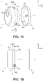
- FIGS. 1A-1C illustrate exploded diagrams at different viewing angles of an IP camera 1 according to one embodiment of the present disclosure.
- the IP camera 1 includes a camera body 11 and a cover 12. As shown in FIG. 1B and FIG. 1C , the camera body 11 has a receiving slot 11S for insertion of a memory card 3.
- the memory card 3 may be, for example, a flash memory card or a subscriber identification module (SIM) card, but the present disclosure is not limited thereto.
- SIM subscriber identification module
- the cover 12 is detachably mounted on a side contoured surface 11c of the camera body 11. Specifically, as shown in FIG. 1A and FIG. 1C , the cover 12 has an opening 12H and an inner surface 12e surrounding the opening 12H.
- the inner surface 12e of the cover 12 is configured to be attached to and disposed around an engaging face 11e of the camera body 11.
- an entrance path P to the receiving slot 11S is blocked by the cover 12 to prevent the memory card 3 in the receiving slot 11S from falling out or being withdrawn from the receiving slot 11S.
- the engaging face 11e is arranged on the ide contoured surface 11c surrounding the camera body 11.
- the receiving slot 11S is concave inwards the camera body 11 from the engaging face 11e, as shown in FIG. 1B and FIG. 1C .
- the engaging face 11e may be one section of the side contoured surface 11c of the camera body 11. In other embodiments, the engaging face 11e may substantially be the same as the side contoured surface 11c of the camera body 11.
- the opening 12H of the cover 12 may have a central axis C which is substantially parallel to the Y axis, as shown in FIGS. 1A-1C .
- the depthof the inner surface 12e along the central axis C is substantially equal to the depth of the engaging face 11e along the Y axis.
- the depth 12a (designated in FIG. 1A ) of the inner surface 12e along the central axis C may be greater than 4 millimeters, so as to ensure the cover 12 can fully block the entrance path P.
- the cover 12 may be a ring structure having an axial length greater than 4 millimeters.
- the depth of the inner surface 12e is substantially equal to the depth of the side contoured surface 11c.
- a design about the particular shape and/or size of the cover 12 may assure blockage of the entrance path P to the receiving slot 11S.
- the opening 12H of the cover 12 is circular in shape.
- the camera body 11 may rotate relative to the cover 12, wherein the rotation axis is substantially parallel to the Y axis depicted in the drawing to freely modify the shooting direction of the camera body 11.
- the shape of the opening 12H of the cover 12 may not be limited to circle; instead, the opening 12H of the cover 12 may substantially be, for example, elliptical, triangular, square, other polygonal and so on.
- the camera body 11 may further include one or more hook structure 113 which may be arranged on the engaging face 11e.
- the hook structure 113 is a resilient structure.
- the hook structure 113 is conductive to elastic deformation in a direction substantially perpendicular to the engaging face 11e. While the cover 12 moves towards the negative Y axis to engage with the camera body 11, the hook structure 13 is deformed inwards the camera body 11 by the press of the cover 12.
- the hook structure 113 returns back right through the stored elastic energy.
- the hook structure 113 may prevent the cover 12 from being loosened towards the positive Y axis.
- the camera body 11 is going to be taken off towards the negative Y axis, it is required to press the hook structure 113 inwards the camera body 11 first. Then, the camera body 11 can be separated from the cover 12.
- the cover 12 may firmly fit on the engaging face 11e of the camera body 11 by the tolerance between the opening 12H of the cover 12 and the camera body 11.
- the one or more hook structure 113 may be omitted.
- the camera body 11 may further include a front portion 111, a stop portion 11ST and a rear portion 112.
- the front portion 111 and the rear portion 112 may respectively be the front and rear of the camera body 11.
- the front portion 111 and the rear portion 112 are separated from each other by the stop portion 11ST.
- a lens 11L of the camera body 11 is disposed on the front portion 111.
- the stop portion 11ST is disposed on a part of the front portion 111 which the engaging face 11e is adjacent to, and the engaging face 11e may be located on the rear portion 112. Specifically, there may be a level difference between the front portion 111 and the engaging face 11e.
- the cover 12 may fit to the camera body 11 only from the rear portion 112 towards the negative Y axis.
- the cover 12 may abut against the stop portion 11ST instead of keeping on moving towards the negative Y axis. At this time, the cover 12 remains on the engaging face 11e.
- the cross-sectional area of the rear portion 112 may be varied gradually along the Y axis. As shown in FIG. 1B , the cross-sectional area of the rear portion 112 gradually decreases towards the positive Y axis. In other words, the cross-sectional area of the camera body 11 which the engaging face 11e is located on gradually decreases in a direction from the front portion 112 to the rear portion 112 (i.e., the positive Y axis). Likewise, the size of the opening 12H of the cover 12 also gradually decreases in the same direction. Therefore, the cover 12 can smoothly fit to the camera body 11 from the rear portion 112 towards the negative Y axis.
- the camera body 11 may further include a connection port 11P.
- the connection port 11P may be, for example, a connection port for a power supply line or a network line to be plugged into.
- the connection port 11P is disposed on the rear portion 112 and concaves inwards the camera body 11 from the side contoured surface 11c, wherein the direction which the connection port 11P is concave towards is perpendicular to the Y axis.
- the connection port 11P is disposed farther away from the front portion 111 of the camera body 11 than the engaging face 11e and the receiving slot 11S.
- the cable connector may prevent the cover 12 from moving towards the positive Y axis.
- the IP camera 1 may send an alert notification, such as sound, blink, or wireless message, to notify user that the cable connector has been removed. Therefore, it may further prevent the memory card 3 from being stolen by others.
- the cover 12 may block the entrance path P to the receiving slot 11S.
- the cover 12 may further serve as a holder to support the weight of the camera body 11.
- FIG. 2 illustrates an exploded diagram of an IP camera 2 according to another embodiment of the present disclosure.
- the cover 22 in the embodiment of FIG. 2 serves as a holder, and the inner surface 22e of the cover 22 additionally serves as a supporting surface to support the weight of the camera body 11.
- the inner surface 22e of the cover 22 is attached to and disposed around the engaging face 11e of the camera body 11, the camera body 11 occupies the opening 22H of the cover 22 and is supported by the inner surface 22e.
- the IP camera 2 may further include a foot 4.
- the foot 4 may be disposed on or fastened on any plane, such as the table, the wall and the ceiling, to support the weight of the IP camera 2 on the plane.
- the foot 4 includes a jointing element 41 connected to the cover 22.
- the jointing element 41 may be, for example, a universal joint.
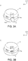
- steps for assembling the IP camera 2 with reference to FIGS. 2-5 . It is understood that these steps may be applied to the embodiment of FIGS. 1A-1C as well.
- the camera body 11 and the cover 22 are separated from each other.
- the memory card 3 is inserted into the receiving slot 11S.
- the memory card 3 does not protrude out from the engaging face 11e.
- the camera body 11 is inserted into the opening 22H of the cover 22 so that the inner surface 22e of the cover 22 is attached to and disposed around the engaging face 11e of the camera body 11.
- the cover 22 may abut against the stop portion 11ST instead of keeping on moving towards the negative Y axis relative to the camera body 11.
- the hook structure 113 may prevent the camera body 11 from being detached from the cover 22 towards the negative Y axis. Meanwhile, the entrance path P to the receiving slot 11S is blocked by the cover 22, so that the memory card 3 cannot leave the receiving slot 11S.
- a cable connector 5 is inserted into the connection port 11P.
- the cable connector 5 prevents the camera body 11 from moving towards the negative Y axis relative to the cover 22. Even if not restricted by the hook structure 113, the camera body 11 still cannot be detached from the cover 22. That is, if it is desired to separate the camera body 11 from the cover 22, or further take the memory card 3 out of the receiving slot 11S, it is required to remove the cable connector 5 first. Then, the camera body 11 can be separated from the cover 22 so that the entrance path P to the receiving slot 11S is no longer blocked by the cover 22, and the memory card 3 is allowed to enter or be taken out of the receiving slot 11S. Through these structures, it may further protect the user's privacy.
Landscapes
- Physics & Mathematics (AREA)
- General Physics & Mathematics (AREA)
- Engineering & Computer Science (AREA)
- Multimedia (AREA)
- Signal Processing (AREA)
- Studio Devices (AREA)
- Camera Bodies And Camera Details Or Accessories (AREA)
Claims (10)
- Internetprotokoll-Kamera (1, 2) mit einem Kamerakörper (11) mit einer eine optische Achse aufweisenden Linse (11L) und einer eine Öffnung (12H, 22H) aufweisenden Abdeckung (12, 22), wobeider Kamerakörper (11) eine zu der optischen Achse parallele Mittelachse und einen Aufnahmeschlitz (11S) zum Einführen einer Speicherkarte (3) aufweist, der Kamerakörper einen vorderen Bereich (111), einen dem vorderen Bereich entgegengesetzten hinteren Bereich (112) und eine konturierte Seitenfläche (11c) um die Mittelachse herum aufweist, die konturierte Seitenfläche (11c) ebenfalls um die Mittelachse herum eine Eingriffsfläche (11e) aufweist, die Eingriffsfläche (11e) in dem hinteren Bereich angeordnet ist, der Einführschlitz aus der Eingriffsfläche (11e) in Richtung und senkrecht zu der Mittelachse in den Kamerakörper ausgenommen ist; unddie Öffnung dieselbe Mittelachse aufweist und an der Vorderseite und der Rückseite der Abdeckung (12, 22) entlang der Mittelachse offen ist, die Abdeckung (12, 22) eine Innenfläche (12e, 22e) um die Mittelachse herum aufweist, die Innenfläche (12e, 22e) eine zu einer Form und einer Größe der Eingriffsfläche (11e) passende Form und Größe aufweist, wobei die Abdeckung (12, 22) geeignet ist, die Eingriffsfläche (11e) abzudecken, und eine Tiefe (12a) der Innenfläche (12e, 22e) entlang der Mittelachse im Wesentlichen gleich einer Tiefe der Eingriffsfläche (11e) entlang der Mittelachse ist;wobei, wenn die Eingriffsfläche (11e) von der Abdeckung (12, 22) bedeckt ist, die Innenfläche (11e, 22e) der Abdeckung 12, 22) an der Eingriffsfläche (11e) des Kamerakörpers (11) angebracht und um diese herum angeordnet ist, so dass ein Eintrittspfad (P) in den Aufnahmeschlitz (11S) durch die Abdeckung (12, 22) blockiert ist.
- Internetprotokoll-Kamera nach Anspruch 1, bei welcher, wenn die Speicherkarte (3) in den Aufnahmeschlitz (11S) eingesetzt ist, die Speicherkarte (3) nicht aus der Eingriffsfläche (11e) vorsteht.
- Internetprotokoll-Kamera nach Anspruch 1, bei welcher, wenn die Eingriffsfläche (11e) von der Abdeckung (12, 22) bedeckt ist, der Kamerakörper (11) in die Öffnung (12H, 22H) der Abdeckung (12) eingesetzt ist und ein Gewicht des Kamerakörpers (11) von der Abdeckung (12, 22) gestützt ist.
- Internetprotokoll-Kamera nach Anspruch 1, bei welcher die Tiefe (12a) der Innenfläche (12e, 22e) entlang der Mittelachse größer als 4 Millimeter ist.
- Internetprotokoll-Kamera nach Anspruch 1, bei welcher die Abdeckung (12, 22) eine Ringstruktur ist, und die Tiefe der Innenfläche (12e, 22e) der Ringstruktur entlang der Mittelachse größer als 4 Millimeter ist.
- Internetprotokoll-Kamera nach Anspruch 1, bei welcher der Kamerakörper (11) ferner einen Anschlagbereich (11ST) aufweist, die Linse (11L) des Kamerakörpers (11) an dem vorderen Bereich (111) angeordnet ist, der Anschlagbereich (11ST) an dem vorderen Bereich (111) der Linse entgegengesetzt angeordnet ist, die Eingriffsfläche (11e) dem Anschlagbereich (11ST) benachbart ist, und ein Außenradius des Anschlagbereichs (11ST) um die Mittelachse größer als ein Radius der Eingriffsfläche (11e) um die Mittelachse ist.
- Internetprotokoll-Kamera nach Anspruch 6, bei welcher der Radius der Eingriffsfläche (11e) in einer Richtung von dem vorderen Bereich (111) zum hinteren Bereich (112) allmählich abnimmt.
- Internetprotokoll-Kamera nach Anspruch 6, bei welcher der Kamerakörper (11) ferner einen Anschlussport (11P) aufweist, der an dem hinteren Bereich (112) angeordnet ist und von der konturierten Seitenfläche (11c) in Richtung der Mittelachse zum Inneren des Kameraköpers (11) konkav ist, wobei der Anschlussport (11P) zum Einführen eines Kabelverbinders (5) geeignet ist, und der Anschlagbereich (11ST), die Eingriffsfläche (11e) und der Anschlussport (11P) nacheinander von dem vorderen Bereich (111) zum hinteren Bereich (112) angeordnet sind.
- Internetprotokoll-Kamera nach Anspruch 8, bei welcher, wenn die Eingriffsfläche (11e) von der Abdeckung (12, 22) bedeckt ist und der Kabelverbinder (5) in den Anschlussport (11P) eingesetzt ist, die Abdeckung (12, 22) an dem Anschlagbereich (11ST) auf der einen Seite und dem Kabelverbinder (5) auf der anderen Seite anliegt, so dass der Kabelverbinder (5) ein Lösen des Kamerakörpers (11) von der Abdeckung (12, 22) verhindert.
- Internetprotokoll-Kamera nach Anspruch 1, bei welcher die Speicherkarte (3) eine Flash-Memory-Karte (3) oder eine Subscriber-Information-Modul-Karte (SIM) (3) ist.
Applications Claiming Priority (1)
| Application Number | Priority Date | Filing Date | Title |
|---|---|---|---|
| CN201721025602.8U CN207070183U (zh) | 2017-08-16 | 2017-08-16 | 网络摄影机 |
Publications (2)
| Publication Number | Publication Date |
|---|---|
| EP3445035A1 EP3445035A1 (de) | 2019-02-20 |
| EP3445035B1 true EP3445035B1 (de) | 2022-12-07 |
Family
ID=61515522
Family Applications (1)
| Application Number | Title | Priority Date | Filing Date |
|---|---|---|---|
| EP18170548.4A Active EP3445035B1 (de) | 2017-08-16 | 2018-05-03 | Ip-kamera mit abdeckung zum blockieren des eintrittspfades in den speicherkartenaufnahmeschlitz |
Country Status (3)
| Country | Link |
|---|---|
| US (1) | US10686970B2 (de) |
| EP (1) | EP3445035B1 (de) |
| CN (1) | CN207070183U (de) |
Families Citing this family (1)
| Publication number | Priority date | Publication date | Assignee | Title |
|---|---|---|---|---|
| KR102525183B1 (ko) * | 2018-04-24 | 2023-04-25 | 한화비전 주식회사 | 감시 카메라 |
Family Cites Families (36)
| Publication number | Priority date | Publication date | Assignee | Title |
|---|---|---|---|---|
| US3415600A (en) | 1967-03-02 | 1968-12-10 | Kenneth A. Yarbrough | Control device for camera stand |
| FR2570331B1 (fr) | 1984-09-14 | 1988-12-02 | Smh Alcatel | Dispositif d'insertion de liasse dans une enveloppe |
| US4740840A (en) | 1985-12-24 | 1988-04-26 | Xedar Corporation | Pyroelectric camera signal processing having interrelated multi-parameter pedestal signal level compensation |
| US4694334A (en) | 1985-12-24 | 1987-09-15 | Xedar Corporation | Pyroelectric camera signal processing having pedestal signal level compensation |
| CN2211614Y (zh) | 1994-08-12 | 1995-11-01 | 许正忠 | 球型摄影机旋转固定架结构 |
| US5581299A (en) | 1995-08-01 | 1996-12-03 | Raney; Robert B. | Multi-functional camera with graphics editor and form stand |
| US7253840B2 (en) * | 2001-06-11 | 2007-08-07 | Fujifilm Corporation | Cradle for digital camera |
| JP3822162B2 (ja) | 2002-10-22 | 2006-09-13 | ヤマサ醤油株式会社 | 醤油及びその用途 |
| JP2005323260A (ja) | 2004-05-11 | 2005-11-17 | Olympus Corp | スタンド装置及びそれを用いる電子機器 |
| DE202004015006U1 (de) | 2004-09-27 | 2004-12-23 | Müller, Jochen, Dr. | Befestigungsvorrichtung für ein Stativ an einer Kamera |
| US8224408B2 (en) * | 2005-01-24 | 2012-07-17 | Ralf Tomasini | Cradle for mobile phones |
| CN2831186Y (zh) | 2005-07-20 | 2006-10-25 | 陈星� | 用于立体照片拍摄的相机专用架 |
| ES2292327B1 (es) | 2005-12-26 | 2009-04-01 | Consejo Superior Investigaciones Cientificas | Mini camara gamma autonoma y con sistema de localizacion, para uso intraquirurgico. |
| US20090179990A1 (en) | 2007-01-20 | 2009-07-16 | Qpixel Technology International, Inc. | Stand-alone video camera |
| USD618269S1 (en) | 2008-04-15 | 2010-06-22 | Brijot Imaging Systems, Inc. | Security camera pedestal mount |
| JP5824888B2 (ja) * | 2011-06-09 | 2015-12-02 | リコーイメージング株式会社 | デジタルカメラ |
| US8531740B1 (en) | 2012-02-23 | 2013-09-10 | Tomasz Wardega | Universal scanning stand for devices equipped with a digital camera |
| CN102891950B (zh) | 2012-10-23 | 2016-03-30 | 王彤 | 拍摄仪适配底座及其传输图像信息的方法 |
| US9519986B1 (en) | 2013-06-20 | 2016-12-13 | Pixar | Using stand-in camera to determine grid for rendering an image from a virtual camera |
| JP5541430B1 (ja) * | 2013-08-19 | 2014-07-09 | ソニー株式会社 | 撮像ユニット、装着装置 |
| USD733781S1 (en) * | 2014-01-27 | 2015-07-07 | Sercomm Corporation | IP camera |
| CN203705805U (zh) | 2014-03-03 | 2014-07-09 | 重庆大学 | 照相机支架 |
| CN203788370U (zh) | 2014-04-25 | 2014-08-20 | 南昌欧菲光电技术有限公司 | 摄像模组底座、摄像模组及电子设备 |
| JP2015215423A (ja) * | 2014-05-08 | 2015-12-03 | ソニー株式会社 | 撮像装置 |
| US9635257B2 (en) | 2014-05-12 | 2017-04-25 | Gopro, Inc. | Dual-microphone camera |
| KR20150144066A (ko) | 2014-06-16 | 2015-12-24 | 삼성전자주식회사 | 스탠드 기능을 구비하는 카메라 클립 및 이를 구비하는 카메라 장치 |
| JP2016024383A (ja) * | 2014-07-22 | 2016-02-08 | ソニー株式会社 | 電子機器 |
| CN204143144U (zh) | 2014-10-10 | 2015-02-04 | 于吉星 | 多角度调整的摄影机脚座 |
| CN204442579U (zh) | 2015-04-08 | 2015-07-01 | 深圳市超维实业有限公司 | 一种带隐蔽网络眼的底座 |
| US9377157B1 (en) | 2015-06-13 | 2016-06-28 | Google Inc. | Camera stand having an unlimited range of motion along an axis of rotation |
| US9388934B1 (en) | 2015-06-13 | 2016-07-12 | Google Inc. | Camera stand having constant resistance for a portion of a range of motion along an axis of rotation |
| CN205509545U (zh) | 2016-02-03 | 2016-08-24 | 安徽清新互联信息科技有限公司 | 一种用于布控球网络摄像机的备用电源 |
| CN205458741U (zh) | 2016-02-29 | 2016-08-17 | 邦盛医疗装备(天津)股份有限公司 | 医用数字摄像系统立柱组件 |
| CN105704358A (zh) | 2016-04-12 | 2016-06-22 | 信利光电股份有限公司 | 一种摄像模组底座及其摄像模组 |
| CN205812179U (zh) | 2016-06-24 | 2016-12-14 | 东莞市德才电子科技有限公司 | 角度可调的摄像头 |
| CN106192801A (zh) | 2016-08-26 | 2016-12-07 | 四川弘毅智慧知识产权运营有限公司 | 拼接式立柱及设有拼接式立柱的智能交通摄像头支撑装置 |
-
2017
- 2017-08-16 CN CN201721025602.8U patent/CN207070183U/zh active Active
-
2018
- 2018-04-12 US US15/951,444 patent/US10686970B2/en active Active
- 2018-05-03 EP EP18170548.4A patent/EP3445035B1/de active Active
Also Published As
| Publication number | Publication date |
|---|---|
| CN207070183U (zh) | 2018-03-02 |
| EP3445035A1 (de) | 2019-02-20 |
| US20190058813A1 (en) | 2019-02-21 |
| US10686970B2 (en) | 2020-06-16 |
Similar Documents
| Publication | Publication Date | Title |
|---|---|---|
| JP3224768U (ja) | スマート携帯電話ケース | |
| CN207491003U (zh) | 移动终端 | |
| CN104333626B (zh) | 移动终端设备 | |
| CN207491004U (zh) | 移动终端 | |
| CN207491006U (zh) | 移动终端 | |
| KR101594367B1 (ko) | 휴대용 단말기 | |
| CN108055426A (zh) | 摄像头组装结构及移动终端 | |
| JP2008252534A (ja) | 携帯端末装置、充電器および携帯端末装置が装着されるアダプタ | |
| US20170366215A1 (en) | I-Scope Cell Phone Smart Case Providing Camera Functonality | |
| CN207491005U (zh) | 移动终端 | |
| CN110972491A (zh) | 一种连接装置及手持云台设备 | |
| KR100800767B1 (ko) | 착탈식 보조 하우징을 구비한 휴대 단말기 및 그의 락킹장치 | |
| US10686970B2 (en) | IP camera having cover for blocking entrance path to memory card receiving slot | |
| CN210920733U (zh) | 一种摄像模组可旋转的智能主机及智能手表 | |
| EP1429531B1 (de) | Tragbares Kommunikationsgerät mit Kamera | |
| CN212588363U (zh) | 一种带云服务的智能手机移动存储设备 | |
| US11006213B1 (en) | Shower entertainment system | |
| CN103581380A (zh) | 一种手机全景镜头 | |
| CN102843887B (zh) | 一种电子设备 | |
| KR100430595B1 (ko) | 영상 통신용 무선 단말기 | |
| KR101005325B1 (ko) | 카메라가 부착된 안경 | |
| CN109842697B (zh) | 移动终端 | |
| CN221058342U (zh) | 摄像头全包覆手机壳 | |
| CN215499225U (zh) | 一种图像采集设备 | |
| CN214014336U (zh) | 一种全方位安全监控摄像头 |
Legal Events
| Date | Code | Title | Description |
|---|---|---|---|
| PUAI | Public reference made under article 153(3) epc to a published international application that has entered the european phase |
Free format text: ORIGINAL CODE: 0009012 |
|
| STAA | Information on the status of an ep patent application or granted ep patent |
Free format text: STATUS: THE APPLICATION HAS BEEN PUBLISHED |
|
| AK | Designated contracting states |
Kind code of ref document: A1 Designated state(s): AL AT BE BG CH CY CZ DE DK EE ES FI FR GB GR HR HU IE IS IT LI LT LU LV MC MK MT NL NO PL PT RO RS SE SI SK SM TR |
|
| AX | Request for extension of the european patent |
Extension state: BA ME |
|
| STAA | Information on the status of an ep patent application or granted ep patent |
Free format text: STATUS: REQUEST FOR EXAMINATION WAS MADE |
|
| 17P | Request for examination filed |
Effective date: 20190425 |
|
| RBV | Designated contracting states (corrected) |
Designated state(s): AL AT BE BG CH CY CZ DE DK EE ES FI FR GB GR HR HU IE IS IT LI LT LU LV MC MK MT NL NO PL PT RO RS SE SI SK SM TR |
|
| STAA | Information on the status of an ep patent application or granted ep patent |
Free format text: STATUS: EXAMINATION IS IN PROGRESS |
|
| 17Q | First examination report despatched |
Effective date: 20200417 |
|
| REG | Reference to a national code |
Ref country code: DE Ref legal event code: R079 Ref document number: 602018043888 Country of ref document: DE Free format text: PREVIOUS MAIN CLASS: H04N0005225000 Ipc: G03B0017020000 |
|
| RIC1 | Information provided on ipc code assigned before grant |
Ipc: H04N 5/225 20060101ALI20220519BHEP Ipc: G03B 17/56 20060101ALI20220519BHEP Ipc: G03B 17/02 20060101AFI20220519BHEP |
|
| GRAP | Despatch of communication of intention to grant a patent |
Free format text: ORIGINAL CODE: EPIDOSNIGR1 |
|
| STAA | Information on the status of an ep patent application or granted ep patent |
Free format text: STATUS: GRANT OF PATENT IS INTENDED |
|
| INTG | Intention to grant announced |
Effective date: 20220704 |
|
| GRAS | Grant fee paid |
Free format text: ORIGINAL CODE: EPIDOSNIGR3 |
|
| GRAA | (expected) grant |
Free format text: ORIGINAL CODE: 0009210 |
|
| STAA | Information on the status of an ep patent application or granted ep patent |
Free format text: STATUS: THE PATENT HAS BEEN GRANTED |
|
| AK | Designated contracting states |
Kind code of ref document: B1 Designated state(s): AL AT BE BG CH CY CZ DE DK EE ES FI FR GB GR HR HU IE IS IT LI LT LU LV MC MK MT NL NO PL PT RO RS SE SI SK SM TR |
|
| REG | Reference to a national code |
Ref country code: GB Ref legal event code: FG4D |
|
| REG | Reference to a national code |
Ref country code: CH Ref legal event code: EP Ref country code: AT Ref legal event code: REF Ref document number: 1536645 Country of ref document: AT Kind code of ref document: T Effective date: 20221215 |
|
| REG | Reference to a national code |
Ref country code: DE Ref legal event code: R096 Ref document number: 602018043888 Country of ref document: DE |
|
| REG | Reference to a national code |
Ref country code: IE Ref legal event code: FG4D |
|
| REG | Reference to a national code |
Ref country code: LT Ref legal event code: MG9D |
|
| REG | Reference to a national code |
Ref country code: NL Ref legal event code: MP Effective date: 20221207 |
|
| PG25 | Lapsed in a contracting state [announced via postgrant information from national office to epo] |
Ref country code: SE Free format text: LAPSE BECAUSE OF FAILURE TO SUBMIT A TRANSLATION OF THE DESCRIPTION OR TO PAY THE FEE WITHIN THE PRESCRIBED TIME-LIMIT Effective date: 20221207 Ref country code: NO Free format text: LAPSE BECAUSE OF FAILURE TO SUBMIT A TRANSLATION OF THE DESCRIPTION OR TO PAY THE FEE WITHIN THE PRESCRIBED TIME-LIMIT Effective date: 20230307 Ref country code: LT Free format text: LAPSE BECAUSE OF FAILURE TO SUBMIT A TRANSLATION OF THE DESCRIPTION OR TO PAY THE FEE WITHIN THE PRESCRIBED TIME-LIMIT Effective date: 20221207 Ref country code: FI Free format text: LAPSE BECAUSE OF FAILURE TO SUBMIT A TRANSLATION OF THE DESCRIPTION OR TO PAY THE FEE WITHIN THE PRESCRIBED TIME-LIMIT Effective date: 20221207 Ref country code: ES Free format text: LAPSE BECAUSE OF FAILURE TO SUBMIT A TRANSLATION OF THE DESCRIPTION OR TO PAY THE FEE WITHIN THE PRESCRIBED TIME-LIMIT Effective date: 20221207 |
|
| REG | Reference to a national code |
Ref country code: AT Ref legal event code: MK05 Ref document number: 1536645 Country of ref document: AT Kind code of ref document: T Effective date: 20221207 |
|
| PG25 | Lapsed in a contracting state [announced via postgrant information from national office to epo] |
Ref country code: RS Free format text: LAPSE BECAUSE OF FAILURE TO SUBMIT A TRANSLATION OF THE DESCRIPTION OR TO PAY THE FEE WITHIN THE PRESCRIBED TIME-LIMIT Effective date: 20221207 Ref country code: PL Free format text: LAPSE BECAUSE OF FAILURE TO SUBMIT A TRANSLATION OF THE DESCRIPTION OR TO PAY THE FEE WITHIN THE PRESCRIBED TIME-LIMIT Effective date: 20221207 Ref country code: LV Free format text: LAPSE BECAUSE OF FAILURE TO SUBMIT A TRANSLATION OF THE DESCRIPTION OR TO PAY THE FEE WITHIN THE PRESCRIBED TIME-LIMIT Effective date: 20221207 Ref country code: HR Free format text: LAPSE BECAUSE OF FAILURE TO SUBMIT A TRANSLATION OF THE DESCRIPTION OR TO PAY THE FEE WITHIN THE PRESCRIBED TIME-LIMIT Effective date: 20221207 Ref country code: GR Free format text: LAPSE BECAUSE OF FAILURE TO SUBMIT A TRANSLATION OF THE DESCRIPTION OR TO PAY THE FEE WITHIN THE PRESCRIBED TIME-LIMIT Effective date: 20230308 |
|
| PG25 | Lapsed in a contracting state [announced via postgrant information from national office to epo] |
Ref country code: NL Free format text: LAPSE BECAUSE OF FAILURE TO SUBMIT A TRANSLATION OF THE DESCRIPTION OR TO PAY THE FEE WITHIN THE PRESCRIBED TIME-LIMIT Effective date: 20221207 |
|
| PG25 | Lapsed in a contracting state [announced via postgrant information from national office to epo] |
Ref country code: SM Free format text: LAPSE BECAUSE OF FAILURE TO SUBMIT A TRANSLATION OF THE DESCRIPTION OR TO PAY THE FEE WITHIN THE PRESCRIBED TIME-LIMIT Effective date: 20221207 Ref country code: RO Free format text: LAPSE BECAUSE OF FAILURE TO SUBMIT A TRANSLATION OF THE DESCRIPTION OR TO PAY THE FEE WITHIN THE PRESCRIBED TIME-LIMIT Effective date: 20221207 Ref country code: PT Free format text: LAPSE BECAUSE OF FAILURE TO SUBMIT A TRANSLATION OF THE DESCRIPTION OR TO PAY THE FEE WITHIN THE PRESCRIBED TIME-LIMIT Effective date: 20230410 Ref country code: EE Free format text: LAPSE BECAUSE OF FAILURE TO SUBMIT A TRANSLATION OF THE DESCRIPTION OR TO PAY THE FEE WITHIN THE PRESCRIBED TIME-LIMIT Effective date: 20221207 Ref country code: CZ Free format text: LAPSE BECAUSE OF FAILURE TO SUBMIT A TRANSLATION OF THE DESCRIPTION OR TO PAY THE FEE WITHIN THE PRESCRIBED TIME-LIMIT Effective date: 20221207 Ref country code: AT Free format text: LAPSE BECAUSE OF FAILURE TO SUBMIT A TRANSLATION OF THE DESCRIPTION OR TO PAY THE FEE WITHIN THE PRESCRIBED TIME-LIMIT Effective date: 20221207 |
|
| PG25 | Lapsed in a contracting state [announced via postgrant information from national office to epo] |
Ref country code: SK Free format text: LAPSE BECAUSE OF FAILURE TO SUBMIT A TRANSLATION OF THE DESCRIPTION OR TO PAY THE FEE WITHIN THE PRESCRIBED TIME-LIMIT Effective date: 20221207 Ref country code: IS Free format text: LAPSE BECAUSE OF FAILURE TO SUBMIT A TRANSLATION OF THE DESCRIPTION OR TO PAY THE FEE WITHIN THE PRESCRIBED TIME-LIMIT Effective date: 20230407 Ref country code: AL Free format text: LAPSE BECAUSE OF FAILURE TO SUBMIT A TRANSLATION OF THE DESCRIPTION OR TO PAY THE FEE WITHIN THE PRESCRIBED TIME-LIMIT Effective date: 20221207 |
|
| REG | Reference to a national code |
Ref country code: DE Ref legal event code: R097 Ref document number: 602018043888 Country of ref document: DE |
|
| PLBE | No opposition filed within time limit |
Free format text: ORIGINAL CODE: 0009261 |
|
| STAA | Information on the status of an ep patent application or granted ep patent |
Free format text: STATUS: NO OPPOSITION FILED WITHIN TIME LIMIT |
|
| PG25 | Lapsed in a contracting state [announced via postgrant information from national office to epo] |
Ref country code: DK Free format text: LAPSE BECAUSE OF FAILURE TO SUBMIT A TRANSLATION OF THE DESCRIPTION OR TO PAY THE FEE WITHIN THE PRESCRIBED TIME-LIMIT Effective date: 20221207 |
|
| 26N | No opposition filed |
Effective date: 20230908 |
|
| PG25 | Lapsed in a contracting state [announced via postgrant information from national office to epo] |
Ref country code: SI Free format text: LAPSE BECAUSE OF FAILURE TO SUBMIT A TRANSLATION OF THE DESCRIPTION OR TO PAY THE FEE WITHIN THE PRESCRIBED TIME-LIMIT Effective date: 20221207 |
|
| REG | Reference to a national code |
Ref country code: CH Ref legal event code: PL |
|
| PG25 | Lapsed in a contracting state [announced via postgrant information from national office to epo] |
Ref country code: MC Free format text: LAPSE BECAUSE OF FAILURE TO SUBMIT A TRANSLATION OF THE DESCRIPTION OR TO PAY THE FEE WITHIN THE PRESCRIBED TIME-LIMIT Effective date: 20221207 |
|
| GBPC | Gb: european patent ceased through non-payment of renewal fee |
Effective date: 20230503 |
|
| REG | Reference to a national code |
Ref country code: BE Ref legal event code: MM Effective date: 20230531 |
|
| PG25 | Lapsed in a contracting state [announced via postgrant information from national office to epo] |
Ref country code: MC Free format text: LAPSE BECAUSE OF FAILURE TO SUBMIT A TRANSLATION OF THE DESCRIPTION OR TO PAY THE FEE WITHIN THE PRESCRIBED TIME-LIMIT Effective date: 20221207 Ref country code: LU Free format text: LAPSE BECAUSE OF NON-PAYMENT OF DUE FEES Effective date: 20230503 Ref country code: LI Free format text: LAPSE BECAUSE OF NON-PAYMENT OF DUE FEES Effective date: 20230531 Ref country code: CH Free format text: LAPSE BECAUSE OF NON-PAYMENT OF DUE FEES Effective date: 20230531 |
|
| REG | Reference to a national code |
Ref country code: IE Ref legal event code: MM4A |
|
| PG25 | Lapsed in a contracting state [announced via postgrant information from national office to epo] |
Ref country code: IE Free format text: LAPSE BECAUSE OF NON-PAYMENT OF DUE FEES Effective date: 20230503 |
|
| PG25 | Lapsed in a contracting state [announced via postgrant information from national office to epo] |
Ref country code: IE Free format text: LAPSE BECAUSE OF NON-PAYMENT OF DUE FEES Effective date: 20230503 Ref country code: GB Free format text: LAPSE BECAUSE OF NON-PAYMENT OF DUE FEES Effective date: 20230503 |
|
| PG25 | Lapsed in a contracting state [announced via postgrant information from national office to epo] |
Ref country code: IT Free format text: LAPSE BECAUSE OF FAILURE TO SUBMIT A TRANSLATION OF THE DESCRIPTION OR TO PAY THE FEE WITHIN THE PRESCRIBED TIME-LIMIT Effective date: 20221207 Ref country code: BE Free format text: LAPSE BECAUSE OF NON-PAYMENT OF DUE FEES Effective date: 20230531 |
|
| PG25 | Lapsed in a contracting state [announced via postgrant information from national office to epo] |
Ref country code: BG Free format text: LAPSE BECAUSE OF FAILURE TO SUBMIT A TRANSLATION OF THE DESCRIPTION OR TO PAY THE FEE WITHIN THE PRESCRIBED TIME-LIMIT Effective date: 20221207 |
|
| PG25 | Lapsed in a contracting state [announced via postgrant information from national office to epo] |
Ref country code: BG Free format text: LAPSE BECAUSE OF FAILURE TO SUBMIT A TRANSLATION OF THE DESCRIPTION OR TO PAY THE FEE WITHIN THE PRESCRIBED TIME-LIMIT Effective date: 20221207 |
|
| PGFP | Annual fee paid to national office [announced via postgrant information from national office to epo] |
Ref country code: DE Payment date: 20250529 Year of fee payment: 8 |
|
| PGFP | Annual fee paid to national office [announced via postgrant information from national office to epo] |
Ref country code: FR Payment date: 20250526 Year of fee payment: 8 |
|
| PG25 | Lapsed in a contracting state [announced via postgrant information from national office to epo] |
Ref country code: CY Free format text: LAPSE BECAUSE OF FAILURE TO SUBMIT A TRANSLATION OF THE DESCRIPTION OR TO PAY THE FEE WITHIN THE PRESCRIBED TIME-LIMIT; INVALID AB INITIO Effective date: 20180503 |
|
| PG25 | Lapsed in a contracting state [announced via postgrant information from national office to epo] |
Ref country code: HU Free format text: LAPSE BECAUSE OF FAILURE TO SUBMIT A TRANSLATION OF THE DESCRIPTION OR TO PAY THE FEE WITHIN THE PRESCRIBED TIME-LIMIT; INVALID AB INITIO Effective date: 20180503 |
|
| PG25 | Lapsed in a contracting state [announced via postgrant information from national office to epo] |
Ref country code: TR Free format text: LAPSE BECAUSE OF FAILURE TO SUBMIT A TRANSLATION OF THE DESCRIPTION OR TO PAY THE FEE WITHIN THE PRESCRIBED TIME-LIMIT Effective date: 20221207 |