EP3445035B1 - Ip camera having cover for blocking entrance path to memory card receiving slot - Google Patents
Ip camera having cover for blocking entrance path to memory card receiving slot Download PDFInfo
- Publication number
- EP3445035B1 EP3445035B1 EP18170548.4A EP18170548A EP3445035B1 EP 3445035 B1 EP3445035 B1 EP 3445035B1 EP 18170548 A EP18170548 A EP 18170548A EP 3445035 B1 EP3445035 B1 EP 3445035B1
- Authority
- EP
- European Patent Office
- Prior art keywords
- cover
- camera body
- engaging face
- central axis
- camera
- Prior art date
- Legal status (The legal status is an assumption and is not a legal conclusion. Google has not performed a legal analysis and makes no representation as to the accuracy of the status listed.)
- Active
Links
Images



Classifications
-
- G—PHYSICS
- G03—PHOTOGRAPHY; CINEMATOGRAPHY; ANALOGOUS TECHNIQUES USING WAVES OTHER THAN OPTICAL WAVES; ELECTROGRAPHY; HOLOGRAPHY
- G03B—APPARATUS OR ARRANGEMENTS FOR TAKING PHOTOGRAPHS OR FOR PROJECTING OR VIEWING THEM; APPARATUS OR ARRANGEMENTS EMPLOYING ANALOGOUS TECHNIQUES USING WAVES OTHER THAN OPTICAL WAVES; ACCESSORIES THEREFOR
- G03B17/00—Details of cameras or camera bodies; Accessories therefor
- G03B17/56—Accessories
- G03B17/561—Support related camera accessories
-
- H—ELECTRICITY
- H04—ELECTRIC COMMUNICATION TECHNIQUE
- H04N—PICTORIAL COMMUNICATION, e.g. TELEVISION
- H04N23/00—Cameras or camera modules comprising electronic image sensors; Control thereof
- H04N23/50—Constructional details
- H04N23/51—Housings
-
- G—PHYSICS
- G03—PHOTOGRAPHY; CINEMATOGRAPHY; ANALOGOUS TECHNIQUES USING WAVES OTHER THAN OPTICAL WAVES; ELECTROGRAPHY; HOLOGRAPHY
- G03B—APPARATUS OR ARRANGEMENTS FOR TAKING PHOTOGRAPHS OR FOR PROJECTING OR VIEWING THEM; APPARATUS OR ARRANGEMENTS EMPLOYING ANALOGOUS TECHNIQUES USING WAVES OTHER THAN OPTICAL WAVES; ACCESSORIES THEREFOR
- G03B17/00—Details of cameras or camera bodies; Accessories therefor
- G03B17/02—Bodies
-
- H—ELECTRICITY
- H04—ELECTRIC COMMUNICATION TECHNIQUE
- H04N—PICTORIAL COMMUNICATION, e.g. TELEVISION
- H04N23/00—Cameras or camera modules comprising electronic image sensors; Control thereof
- H04N23/50—Constructional details
Definitions
- the disclosure relates in general to an IP camera, and more particularly to an IP camera having a cover for blocking an entrance path to a memory card receiving slot.
- IP Internet Protocol
- US 2002/186317 A1 discloses a cradle for a digital camera which is capable of confirming a display screen of the camera, changing the recording medium or battery, or mounting or demounting a communication cable or the like while the camera is being mounted on the cradle without deteriorating the camera holding.
- US 2015/326748 A1 discloses a camera which is configured with multiple microphones to reduce wind noise in audio data collected by the camera.
- CN 205 812 179 U discloses an angle-adjustable camera comprising a base and a camera body in which the camera body can rotate relative to the base.
- US 2009/117946 A1 discloses a Cradle for a mobile phone, comprising: a rear bearing surface; left and right side walls; and two guide rails being located on the front side of said left and right side walls and protruding laterally from said side walls; and a bottom part comprising a connector element for mechanically and electrically engaging a bottom connector of said mobile phone.
- the disclosure is directed to an IP camera.
- a particular shape of the cover may assure a blockage of the entrance path to the receiving slot to prevent the memory card from being lost.
- the embodiment of the present invention is reflected in independent claim 1.
- the preferred embodiments of the present invention are reflected in dependent claims 2 to 10.
- an IP camera includes a camera body and a cover.
- the camera body includes an engaging face and has a receiving slot.
- the engaging face is arranged on a side contoured surface surrounding the camera body.
- the receiving slot is concave inwards the camera body from the engaging face for insertion of a memory card.
- the cover has an opening and an inner surface surrounding the opening.
- the inner surface of the cover is configured to be attached to and disposed around the engaging face of the camera body.
- the cover is configured to block an entrance path to the receiving slot when the inner surface of the cover is attached to and disposed around the engaging face of the camera body.
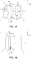
- FIGS. 1A-1C illustrate exploded diagrams at different viewing angles of an IP camera 1 according to one embodiment of the present disclosure.
- the IP camera 1 includes a camera body 11 and a cover 12. As shown in FIG. 1B and FIG. 1C , the camera body 11 has a receiving slot 11S for insertion of a memory card 3.
- the memory card 3 may be, for example, a flash memory card or a subscriber identification module (SIM) card, but the present disclosure is not limited thereto.
- SIM subscriber identification module
- the cover 12 is detachably mounted on a side contoured surface 11c of the camera body 11. Specifically, as shown in FIG. 1A and FIG. 1C , the cover 12 has an opening 12H and an inner surface 12e surrounding the opening 12H.
- the inner surface 12e of the cover 12 is configured to be attached to and disposed around an engaging face 11e of the camera body 11.
- an entrance path P to the receiving slot 11S is blocked by the cover 12 to prevent the memory card 3 in the receiving slot 11S from falling out or being withdrawn from the receiving slot 11S.
- the engaging face 11e is arranged on the ide contoured surface 11c surrounding the camera body 11.
- the receiving slot 11S is concave inwards the camera body 11 from the engaging face 11e, as shown in FIG. 1B and FIG. 1C .
- the engaging face 11e may be one section of the side contoured surface 11c of the camera body 11. In other embodiments, the engaging face 11e may substantially be the same as the side contoured surface 11c of the camera body 11.
- the opening 12H of the cover 12 may have a central axis C which is substantially parallel to the Y axis, as shown in FIGS. 1A-1C .
- the depthof the inner surface 12e along the central axis C is substantially equal to the depth of the engaging face 11e along the Y axis.
- the depth 12a (designated in FIG. 1A ) of the inner surface 12e along the central axis C may be greater than 4 millimeters, so as to ensure the cover 12 can fully block the entrance path P.
- the cover 12 may be a ring structure having an axial length greater than 4 millimeters.
- the depth of the inner surface 12e is substantially equal to the depth of the side contoured surface 11c.
- a design about the particular shape and/or size of the cover 12 may assure blockage of the entrance path P to the receiving slot 11S.
- the opening 12H of the cover 12 is circular in shape.
- the camera body 11 may rotate relative to the cover 12, wherein the rotation axis is substantially parallel to the Y axis depicted in the drawing to freely modify the shooting direction of the camera body 11.
- the shape of the opening 12H of the cover 12 may not be limited to circle; instead, the opening 12H of the cover 12 may substantially be, for example, elliptical, triangular, square, other polygonal and so on.
- the camera body 11 may further include one or more hook structure 113 which may be arranged on the engaging face 11e.
- the hook structure 113 is a resilient structure.
- the hook structure 113 is conductive to elastic deformation in a direction substantially perpendicular to the engaging face 11e. While the cover 12 moves towards the negative Y axis to engage with the camera body 11, the hook structure 13 is deformed inwards the camera body 11 by the press of the cover 12.
- the hook structure 113 returns back right through the stored elastic energy.
- the hook structure 113 may prevent the cover 12 from being loosened towards the positive Y axis.
- the camera body 11 is going to be taken off towards the negative Y axis, it is required to press the hook structure 113 inwards the camera body 11 first. Then, the camera body 11 can be separated from the cover 12.
- the cover 12 may firmly fit on the engaging face 11e of the camera body 11 by the tolerance between the opening 12H of the cover 12 and the camera body 11.
- the one or more hook structure 113 may be omitted.
- the camera body 11 may further include a front portion 111, a stop portion 11ST and a rear portion 112.
- the front portion 111 and the rear portion 112 may respectively be the front and rear of the camera body 11.
- the front portion 111 and the rear portion 112 are separated from each other by the stop portion 11ST.
- a lens 11L of the camera body 11 is disposed on the front portion 111.
- the stop portion 11ST is disposed on a part of the front portion 111 which the engaging face 11e is adjacent to, and the engaging face 11e may be located on the rear portion 112. Specifically, there may be a level difference between the front portion 111 and the engaging face 11e.
- the cover 12 may fit to the camera body 11 only from the rear portion 112 towards the negative Y axis.
- the cover 12 may abut against the stop portion 11ST instead of keeping on moving towards the negative Y axis. At this time, the cover 12 remains on the engaging face 11e.
- the cross-sectional area of the rear portion 112 may be varied gradually along the Y axis. As shown in FIG. 1B , the cross-sectional area of the rear portion 112 gradually decreases towards the positive Y axis. In other words, the cross-sectional area of the camera body 11 which the engaging face 11e is located on gradually decreases in a direction from the front portion 112 to the rear portion 112 (i.e., the positive Y axis). Likewise, the size of the opening 12H of the cover 12 also gradually decreases in the same direction. Therefore, the cover 12 can smoothly fit to the camera body 11 from the rear portion 112 towards the negative Y axis.
- the camera body 11 may further include a connection port 11P.
- the connection port 11P may be, for example, a connection port for a power supply line or a network line to be plugged into.
- the connection port 11P is disposed on the rear portion 112 and concaves inwards the camera body 11 from the side contoured surface 11c, wherein the direction which the connection port 11P is concave towards is perpendicular to the Y axis.
- the connection port 11P is disposed farther away from the front portion 111 of the camera body 11 than the engaging face 11e and the receiving slot 11S.
- the cable connector may prevent the cover 12 from moving towards the positive Y axis.
- the IP camera 1 may send an alert notification, such as sound, blink, or wireless message, to notify user that the cable connector has been removed. Therefore, it may further prevent the memory card 3 from being stolen by others.
- the cover 12 may block the entrance path P to the receiving slot 11S.
- the cover 12 may further serve as a holder to support the weight of the camera body 11.
- FIG. 2 illustrates an exploded diagram of an IP camera 2 according to another embodiment of the present disclosure.
- the cover 22 in the embodiment of FIG. 2 serves as a holder, and the inner surface 22e of the cover 22 additionally serves as a supporting surface to support the weight of the camera body 11.
- the inner surface 22e of the cover 22 is attached to and disposed around the engaging face 11e of the camera body 11, the camera body 11 occupies the opening 22H of the cover 22 and is supported by the inner surface 22e.
- the IP camera 2 may further include a foot 4.
- the foot 4 may be disposed on or fastened on any plane, such as the table, the wall and the ceiling, to support the weight of the IP camera 2 on the plane.
- the foot 4 includes a jointing element 41 connected to the cover 22.
- the jointing element 41 may be, for example, a universal joint.
- steps for assembling the IP camera 2 with reference to FIGS. 2-5 . It is understood that these steps may be applied to the embodiment of FIGS. 1A-1C as well.
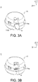
- the camera body 11 and the cover 22 are separated from each other.
- the memory card 3 is inserted into the receiving slot 11S.
- the memory card 3 does not protrude out from the engaging face 11e.
- the camera body 11 is inserted into the opening 22H of the cover 22 so that the inner surface 22e of the cover 22 is attached to and disposed around the engaging face 11e of the camera body 11.
- the cover 22 may abut against the stop portion 11ST instead of keeping on moving towards the negative Y axis relative to the camera body 11.
- the hook structure 113 may prevent the camera body 11 from being detached from the cover 22 towards the negative Y axis. Meanwhile, the entrance path P to the receiving slot 11S is blocked by the cover 22, so that the memory card 3 cannot leave the receiving slot 11S.
- a cable connector 5 is inserted into the connection port 11P.
- the cable connector 5 prevents the camera body 11 from moving towards the negative Y axis relative to the cover 22. Even if not restricted by the hook structure 113, the camera body 11 still cannot be detached from the cover 22. That is, if it is desired to separate the camera body 11 from the cover 22, or further take the memory card 3 out of the receiving slot 11S, it is required to remove the cable connector 5 first. Then, the camera body 11 can be separated from the cover 22 so that the entrance path P to the receiving slot 11S is no longer blocked by the cover 22, and the memory card 3 is allowed to enter or be taken out of the receiving slot 11S. Through these structures, it may further protect the user's privacy.
Landscapes
- Physics & Mathematics (AREA)
- General Physics & Mathematics (AREA)
- Engineering & Computer Science (AREA)
- Multimedia (AREA)
- Signal Processing (AREA)
- Studio Devices (AREA)
- Camera Bodies And Camera Details Or Accessories (AREA)
Description
- The disclosure relates in general to an IP camera, and more particularly to an IP camera having a cover for blocking an entrance path to a memory card receiving slot.
- In the daily lives, various Internet Protocol (IP) cameras have been common not only indoors but also outdoors. The IP camera can transmit images and/or sounds to a remote host via the Internet. In addition, some IP cameras can store these images and/or sounds in a memory card.
US 2002/186317 A1 discloses a cradle for a digital camera which is capable of confirming a display screen of the camera, changing the recording medium or battery, or mounting or demounting a communication cable or the like while the camera is being mounted on the cradle without deteriorating the camera holding.US 2015/326748 A1 discloses a camera which is configured with multiple microphones to reduce wind noise in audio data collected by the camera.CN 205 812 179 U discloses an angle-adjustable camera comprising a base and a camera body in which the camera body can rotate relative to the base.US 2009/117946 A1 discloses a Cradle for a mobile phone, comprising: a rear bearing surface; left and right side walls; and two guide rails being located on the front side of said left and right side walls and protruding laterally from said side walls; and a bottom part comprising a connector element for mechanically and electrically engaging a bottom connector of said mobile phone. - However, there is a risk that the memory card of the IP camera may be lost.
- The disclosure is directed to an IP camera. A particular shape of the cover may assure a blockage of the entrance path to the receiving slot to prevent the memory card from being lost. The embodiment of the present invention is reflected in
independent claim 1. The preferred embodiments of the present invention are reflected independent claims 2 to 10. - According to one aspect, an IP camera is provided. The IP camera includes a camera body and a cover. The camera body includes an engaging face and has a receiving slot. The engaging face is arranged on a side contoured surface surrounding the camera body. The receiving slot is concave inwards the camera body from the engaging face for insertion of a memory card. The cover has an opening and an inner surface surrounding the opening. The inner surface of the cover is configured to be attached to and disposed around the engaging face of the camera body. The cover is configured to block an entrance path to the receiving slot when the inner surface of the cover is attached to and disposed around the engaging face of the camera body.
-
-
FIGS. 1A-1C illustrate exploded diagrams at different viewing angles of an IP camera according to one embodiment of the present disclosure. -
FIG 2 ,FIG. 3A ,FIG. 3B ,FIG. 4 and FIG. 5 illustrate schematic drawings showing how to assemble an IP camera according to another embodiment of the present disclosure. - In the following detailed description, for purposes of explanation, numerous specific details are set forth in order to provide a thorough understanding of the disclosed embodiments. It will be apparent, however, that one or more embodiments may be practiced without these specific details. In other instances, well-known structures and devices are schematically shown in order to simplify the drawing.
- Referring to
FIGS. 1A-1C, FIGS. 1A-1C illustrate exploded diagrams at different viewing angles of anIP camera 1 according to one embodiment of the present disclosure. TheIP camera 1 includes acamera body 11 and acover 12. As shown inFIG. 1B andFIG. 1C , thecamera body 11 has a receivingslot 11S for insertion of amemory card 3. Thememory card 3 may be, for example, a flash memory card or a subscriber identification module (SIM) card, but the present disclosure is not limited thereto. Thecover 12 is detachably mounted on a side contouredsurface 11c of thecamera body 11. Specifically, as shown inFIG. 1A andFIG. 1C , thecover 12 has an opening 12H and aninner surface 12e surrounding the opening 12H. Theinner surface 12e of thecover 12 is configured to be attached to and disposed around anengaging face 11e of thecamera body 11. When theinner surface 12e of thecover 12 is attached to and disposed around anengaging face 11e of thecamera body 11, an entrance path P to the receivingslot 11S is blocked by thecover 12 to prevent thememory card 3 in thereceiving slot 11S from falling out or being withdrawn from thereceiving slot 11S. - In detail, the
engaging face 11e is arranged on the ide contouredsurface 11c surrounding thecamera body 11. Thereceiving slot 11S is concave inwards thecamera body 11 from theengaging face 11e, as shown inFIG. 1B andFIG. 1C . In one embodiment, theengaging face 11e may be one section of the side contouredsurface 11c of thecamera body 11. In other embodiments, theengaging face 11e may substantially be the same as the side contouredsurface 11c of thecamera body 11. - The opening 12H of the
cover 12 may have a central axis C which is substantially parallel to the Y axis, as shown inFIGS. 1A-1C . In one embodiment, the depthof theinner surface 12e along the central axis C is substantially equal to the depth of theengaging face 11e along the Y axis. For example, thedepth 12a (designated inFIG. 1A ) of theinner surface 12e along the central axis C may be greater than 4 millimeters, so as to ensure thecover 12 can fully block the entrance path P. In another embodiment, thecover 12 may be a ring structure having an axial length greater than 4 millimeters. Under a condition that theengaging face 11e is substantially correspond to the side contouredsurface 11c of thecamera body 11, the depth of theinner surface 12e is substantially equal to the depth of the side contouredsurface 11c. Thus, a design about the particular shape and/or size of thecover 12 may assure blockage of the entrance path P to thereceiving slot 11S. - In the present embodiment, the opening 12H of the
cover 12 is circular in shape. Thus, when theinner surface 12e of thecover 12 is attached to and disposed around theengaging face 11e of thecamera body 11, thecamera body 11 may rotate relative to thecover 12, wherein the rotation axis is substantially parallel to the Y axis depicted in the drawing to freely modify the shooting direction of thecamera body 11. In other embodiments, the shape of the opening 12H of thecover 12 may not be limited to circle; instead, the opening 12H of thecover 12 may substantially be, for example, elliptical, triangular, square, other polygonal and so on. - In addition, the
camera body 11 may further include one ormore hook structure 113 which may be arranged on theengaging face 11e. In the present embodiment, thehook structure 113 is a resilient structure. In detail, thehook structure 113 is conductive to elastic deformation in a direction substantially perpendicular to theengaging face 11e. While thecover 12 moves towards the negative Y axis to engage with thecamera body 11, the hook structure 13 is deformed inwards thecamera body 11 by the press of thecover 12. When theinner surface 12e of thecover 12 is attached to and disposed around the engagingface 11e of thecamera body 11, thehook structure 113 returns back right through the stored elastic energy. Thus, thehook structure 113 may prevent thecover 12 from being loosened towards the positive Y axis. Furthermore, if thecamera body 11 is going to be taken off towards the negative Y axis, it is required to press thehook structure 113 inwards thecamera body 11 first. Then, thecamera body 11 can be separated from thecover 12. - In other embodiments, the
cover 12 may firmly fit on theengaging face 11e of thecamera body 11 by the tolerance between theopening 12H of thecover 12 and thecamera body 11. Thus, the one ormore hook structure 113 may be omitted. - Referring to
FIG. 1A and FIG. 1B , thecamera body 11 may further include afront portion 111, a stop portion 11ST and arear portion 112. Thefront portion 111 and therear portion 112 may respectively be the front and rear of thecamera body 11. Thefront portion 111 and therear portion 112 are separated from each other by the stop portion 11ST. Here, alens 11L of thecamera body 11 is disposed on thefront portion 111. The stop portion 11ST is disposed on a part of thefront portion 111 which theengaging face 11e is adjacent to, and theengaging face 11e may be located on therear portion 112. Specifically, there may be a level difference between thefront portion 111 and theengaging face 11e. In other words, there may be a level difference between thefront portion 111 and therear portion 112, and the level difference is right where the stop portion 11ST is disposed. That is, a cross-sectional area of thecamera body 11 which the stop portion 11ST is located on is larger than a cross-sectional area of thecamera body 11 which theengaging face 11e is located on. Therefore, thecover 12 may fit to thecamera body 11 only from therear portion 112 towards the negative Y axis. When theinner surface 12e of thecover 12 is attached to and disposed around the engagingface 11e of thecamera body 11, thecover 12 may abut against the stop portion 11ST instead of keeping on moving towards the negative Y axis. At this time, thecover 12 remains on theengaging face 11e. - On the other hand, in one embodiment, the cross-sectional area of the
rear portion 112 may be varied gradually along the Y axis. As shown inFIG. 1B , the cross-sectional area of therear portion 112 gradually decreases towards the positive Y axis. In other words, the cross-sectional area of thecamera body 11 which theengaging face 11e is located on gradually decreases in a direction from thefront portion 112 to the rear portion 112 (i.e., the positive Y axis). Likewise, the size of theopening 12H of thecover 12 also gradually decreases in the same direction. Therefore, thecover 12 can smoothly fit to thecamera body 11 from therear portion 112 towards the negative Y axis. - Referring to
FIG. 1C , thecamera body 11 may further include aconnection port 11P. Theconnection port 11P may be, for example, a connection port for a power supply line or a network line to be plugged into. Theconnection port 11P is disposed on therear portion 112 and concaves inwards thecamera body 11 from the side contouredsurface 11c, wherein the direction which theconnection port 11P is concave towards is perpendicular to the Y axis. Moreover, theconnection port 11P is disposed farther away from thefront portion 111 of thecamera body 11 than the engagingface 11e and the receivingslot 11S. Under such a design, in a condition that a cable connector is inserted into theconnection port 11P when thecover 12 engages with thecamera body 11, the cable connector may prevent thecover 12 from moving towards the positive Y axis. In this case, it is required to remove the cable connector from theconnection port 11P first, and only then can thecover 12 be separated from thecamera body 11. After that, thememory card 3 received in the receivingslot 11S can be taken out. However, once the cable connector is removed from theconnection port 11P under a normal operating state, theIP camera 1 may send an alert notification, such as sound, blink, or wireless message, to notify user that the cable connector has been removed. Therefore, it may further prevent thememory card 3 from being stolen by others. - In a condition of engaging with the
camera body 11, thecover 12 may block the entrance path P to the receivingslot 11S. In another embodiment, thecover 12 may further serve as a holder to support the weight of thecamera body 11. - Referring to
FIG. 2, FIG. 2 illustrates an exploded diagram of anIP camera 2 according to another embodiment of the present disclosure. The difference between the embodiment ofFIGS. 1A-1C and the embodiment ofFIG. 2 is that thecover 22 in the embodiment ofFIG. 2 serves as a holder, and theinner surface 22e of thecover 22 additionally serves as a supporting surface to support the weight of thecamera body 11. When theinner surface 22e of thecover 22 is attached to and disposed around the engagingface 11e of thecamera body 11, thecamera body 11 occupies theopening 22H of thecover 22 and is supported by theinner surface 22e. - As shown in
FIG. 2 , theIP camera 2 may further include afoot 4. Thefoot 4 may be disposed on or fastened on any plane, such as the table, the wall and the ceiling, to support the weight of theIP camera 2 on the plane. Thefoot 4 includes ajointing element 41 connected to thecover 22. Thejointing element 41 may be, for example, a universal joint. - The following content describes steps for assembling the
IP camera 2 with reference toFIGS. 2-5 . It is understood that these steps may be applied to the embodiment ofFIGS. 1A-1C as well. As shown inFIG. 2 , in the first step, thecamera body 11 and thecover 22 are separated from each other. - Sequentially, as shown in
FIG. 3A , thememory card 3 is inserted into the receivingslot 11S. As shown inFIG. 3B , when thememory card 3 is received in the receivingslot 11S, thememory card 3 does not protrude out from the engagingface 11e. - Afterwards, as shown in
FIG. 4 , thecamera body 11 is inserted into theopening 22H of thecover 22 so that theinner surface 22e of thecover 22 is attached to and disposed around the engagingface 11e of thecamera body 11. At the same time, thecover 22 may abut against the stop portion 11ST instead of keeping on moving towards the negative Y axis relative to thecamera body 11. On the other hand, thehook structure 113 may prevent thecamera body 11 from being detached from thecover 22 towards the negative Y axis. Meanwhile, the entrance path P to the receivingslot 11S is blocked by thecover 22, so that thememory card 3 cannot leave the receivingslot 11S. - Lastly, as shown in
FIG. 5 , acable connector 5 is inserted into theconnection port 11P. Thecable connector 5 prevents thecamera body 11 from moving towards the negative Y axis relative to thecover 22. Even if not restricted by thehook structure 113, thecamera body 11 still cannot be detached from thecover 22. That is, if it is desired to separate thecamera body 11 from thecover 22, or further take thememory card 3 out of the receivingslot 11S, it is required to remove thecable connector 5 first. Then, thecamera body 11 can be separated from thecover 22 so that the entrance path P to the receivingslot 11S is no longer blocked by thecover 22, and thememory card 3 is allowed to enter or be taken out of the receivingslot 11S. Through these structures, it may further protect the user's privacy. - It will be apparent to those skilled in the art that various modifications and variations can be made to the disclosed embodiments. It is intended that the specification and examples be considered as exemplary only, with a true scope of the disclosure being indicated by the following claims.
Claims (10)
- An internet protocol camera (1, 2) comprising a camera body (11) comprisinga lens (11L) having an optical axis, and a cover (12, 22) having an opening (12H, 22H), whereinthe camera body (11) has a central axis parallel to the optical axis and a receiving slot (11S) for insertion of a memory card (3), the camera body comprises a front portion (111), a rear portion (112) opposite to the front portion (111) and a side contoured surface (11c) around the central axis, the side contoured surface (11c) has an engaging face (11e) also around the central axis, the engaging face (11e) is located on the rear portion, the receiving slot is recessed into the camera body from the engaging face (11e) in a direction towards and perpendicular to the central axis; andthe opening has the same central axis and is open at front and back of the cover (12, 22) along the central axis, the cover (12, 22) comprises an inner surface (12e, 22e) around the central axis, the inner surface (12e, 22e) has a shape and a size fitting a shape and a size of the engaging face (11e), wherein the cover (12, 22) is adapted to cover the engaging face (11e), and a depth (12a) of the inner surface (12e, 22e) along the central axis is substantially equal to a depth of the engaging face (11e) along the central axis;wherein when the engaging face (11e) is covered by the cover (12, 22), the inner surface (12e, 22e) of the cover (12, 22) is attached to and disposed around the engaging face (11e) of the camera body (11), so that an entrance path (P) to the receiving slot (11S) is blocked by the cover (12, 22).
- The internet protocol camera according to claim 1, wherein when the memory card (3) is inserted into the receiving slot (11S), the memory card (3) does not protrude out from the engaging face (11e).
- The internet protocol camera according to claim 1, wherein when the engaging face (11e) is covered by the cover (12, 22), the camera body (11) is inserted into the opening (12H, 22H) of the cover (12, 22) and a weight of the camera body (11) is supported by the cover (12, 22).
- The internet protocol camera according to claim 1, wherein the depth (12a) of the inner surface (12e, 22e) along the central axis is greater than 4 millimeters.
- The internet protocol camera according to claim 1, wherein the cover (12, 22) is a ring structure, and the depth of the inner surface (12e, 22e) of the ring structure is greater than 4 millimeters along the central axis.
- The internet protocol camera according to claim 1, wherein the camera body (11) further comprises a stop portion (11ST), the lens (11L) of the camera body (11) is disposed on the front portion (111), the stop portion (11ST) is disposed on the front portion (111) opposite to the lens, the engaging face (11e) is adjacent to the stop portion (11ST), and an outer radius of the stop portion (11ST) around the central axis is larger than a radius of the engaging face (11e) around the central axis.
- The internet protocol camera according to claim 6, wherein the radius of the engaging face (11e) gradually decreases in a direction from the front portion (111) to the rear portion (112).
- The internet protocol camera according to claim 6, wherein the camera body (11) further comprises a connection port (11P) disposed on the rear portion (112) and being concave inwards the camera body (11) from the side contoured surface (11c) towards the central axis, the connection port (11P) is adapted for an insertion of a cable connector (5), and the stop portion (11ST), the engaging face (11e) and the connection port (11P) are arranged in order from the front portion (111) to the rear portion (112).
- The internet protocol camera according to claim 8, wherein when the engaging face (11e) is covered by the cover (12, 22) and the cable connector (5) is inserted into the connection port (11P), the cover (12, 22) abuts against the stop portion (11ST) on one side and the cable connector (5) on the other side, so that the cable connector (5) prevents the camera body (11) from being detached from the cover (12, 22).
- The internet protocol camera according to claim 1, wherein the memory card (3) is a flash memory card (3) or a subscriber identification module (SIM) card (3).
Applications Claiming Priority (1)
| Application Number | Priority Date | Filing Date | Title |
|---|---|---|---|
| CN201721025602.8U CN207070183U (en) | 2017-08-16 | 2017-08-16 | Network camera |
Publications (2)
| Publication Number | Publication Date |
|---|---|
| EP3445035A1 EP3445035A1 (en) | 2019-02-20 |
| EP3445035B1 true EP3445035B1 (en) | 2022-12-07 |
Family
ID=61515522
Family Applications (1)
| Application Number | Title | Priority Date | Filing Date |
|---|---|---|---|
| EP18170548.4A Active EP3445035B1 (en) | 2017-08-16 | 2018-05-03 | Ip camera having cover for blocking entrance path to memory card receiving slot |
Country Status (3)
| Country | Link |
|---|---|
| US (1) | US10686970B2 (en) |
| EP (1) | EP3445035B1 (en) |
| CN (1) | CN207070183U (en) |
Families Citing this family (1)
| Publication number | Priority date | Publication date | Assignee | Title |
|---|---|---|---|---|
| KR102525183B1 (en) * | 2018-04-24 | 2023-04-25 | 한화비전 주식회사 | Security camera |
Family Cites Families (36)
| Publication number | Priority date | Publication date | Assignee | Title |
|---|---|---|---|---|
| US3415600A (en) | 1967-03-02 | 1968-12-10 | Kenneth A. Yarbrough | Control device for camera stand |
| FR2570331B1 (en) | 1984-09-14 | 1988-12-02 | Smh Alcatel | DEVICE FOR INSERTING LIASSE IN AN ENVELOPE |
| US4740840A (en) | 1985-12-24 | 1988-04-26 | Xedar Corporation | Pyroelectric camera signal processing having interrelated multi-parameter pedestal signal level compensation |
| US4694334A (en) | 1985-12-24 | 1987-09-15 | Xedar Corporation | Pyroelectric camera signal processing having pedestal signal level compensation |
| CN2211614Y (en) | 1994-08-12 | 1995-11-01 | 许正忠 | Spherical Camera Rotation Fixture Structure |
| US5581299A (en) | 1995-08-01 | 1996-12-03 | Raney; Robert B. | Multi-functional camera with graphics editor and form stand |
| US7253840B2 (en) * | 2001-06-11 | 2007-08-07 | Fujifilm Corporation | Cradle for digital camera |
| JP3822162B2 (en) | 2002-10-22 | 2006-09-13 | ヤマサ醤油株式会社 | Soy sauce and its use |
| JP2005323260A (en) | 2004-05-11 | 2005-11-17 | Olympus Corp | Stand device and electronic apparatus using it |
| DE202004015006U1 (en) | 2004-09-27 | 2004-12-23 | Müller, Jochen, Dr. | Mounting device for a tripod on a camera |
| US8224408B2 (en) * | 2005-01-24 | 2012-07-17 | Ralf Tomasini | Cradle for mobile phones |
| CN2831186Y (en) | 2005-07-20 | 2006-10-25 | 陈星� | Special camera stand for shooting 3-D photograph |
| ES2292327B1 (en) | 2005-12-26 | 2009-04-01 | Consejo Superior Investigaciones Cientificas | MINI CAMERA GAMMA AUTONOMA AND WITH LOCATION SYSTEM, FOR INTRACHIRURGICAL USE. |
| US20090179990A1 (en) | 2007-01-20 | 2009-07-16 | Qpixel Technology International, Inc. | Stand-alone video camera |
| USD618269S1 (en) | 2008-04-15 | 2010-06-22 | Brijot Imaging Systems, Inc. | Security camera pedestal mount |
| JP5824888B2 (en) * | 2011-06-09 | 2015-12-02 | リコーイメージング株式会社 | Digital camera |
| US8531740B1 (en) | 2012-02-23 | 2013-09-10 | Tomasz Wardega | Universal scanning stand for devices equipped with a digital camera |
| CN102891950B (en) | 2012-10-23 | 2016-03-30 | 王彤 | The method of the adaptive base of recording instrument and transmitting image information thereof |
| US9519986B1 (en) | 2013-06-20 | 2016-12-13 | Pixar | Using stand-in camera to determine grid for rendering an image from a virtual camera |
| JP5541430B1 (en) * | 2013-08-19 | 2014-07-09 | ソニー株式会社 | Imaging unit, mounting device |
| USD733781S1 (en) * | 2014-01-27 | 2015-07-07 | Sercomm Corporation | IP camera |
| CN203705805U (en) | 2014-03-03 | 2014-07-09 | 重庆大学 | Camera stand |
| CN203788370U (en) | 2014-04-25 | 2014-08-20 | 南昌欧菲光电技术有限公司 | Camera module pedestal, camera module and electronic device |
| JP2015215423A (en) * | 2014-05-08 | 2015-12-03 | ソニー株式会社 | Imaging device |
| US9635257B2 (en) | 2014-05-12 | 2017-04-25 | Gopro, Inc. | Dual-microphone camera |
| KR20150144066A (en) | 2014-06-16 | 2015-12-24 | 삼성전자주식회사 | Camera clip with standing funtion and camera device haing the same |
| JP2016024383A (en) * | 2014-07-22 | 2016-02-08 | ソニー株式会社 | Electronic device |
| CN204143144U (en) | 2014-10-10 | 2015-02-04 | 于吉星 | Multi-angle adjustable camera feet |
| CN204442579U (en) | 2015-04-08 | 2015-07-01 | 深圳市超维实业有限公司 | A kind of base with hidden web eye |
| US9377157B1 (en) | 2015-06-13 | 2016-06-28 | Google Inc. | Camera stand having an unlimited range of motion along an axis of rotation |
| US9388934B1 (en) | 2015-06-13 | 2016-07-12 | Google Inc. | Camera stand having constant resistance for a portion of a range of motion along an axis of rotation |
| CN205509545U (en) | 2016-02-03 | 2016-08-24 | 安徽清新互联信息科技有限公司 | A stand -by power supply for cloth ball control internet protocol camera |
| CN205458741U (en) | 2016-02-29 | 2016-08-17 | 邦盛医疗装备(天津)股份有限公司 | Medical digital camera system stand subassembly |
| CN105704358A (en) | 2016-04-12 | 2016-06-22 | 信利光电股份有限公司 | Camera module group pedestal and camera module group |
| CN205812179U (en) | 2016-06-24 | 2016-12-14 | 东莞市德才电子科技有限公司 | Camera with adjustable angle |
| CN106192801A (en) | 2016-08-26 | 2016-12-07 | 四川弘毅智慧知识产权运营有限公司 | Splice-type upright post and be provided with the intelligent transportation photographic head support means of splice-type upright post |
-
2017
- 2017-08-16 CN CN201721025602.8U patent/CN207070183U/en active Active
-
2018
- 2018-04-12 US US15/951,444 patent/US10686970B2/en active Active
- 2018-05-03 EP EP18170548.4A patent/EP3445035B1/en active Active
Also Published As
| Publication number | Publication date |
|---|---|
| CN207070183U (en) | 2018-03-02 |
| EP3445035A1 (en) | 2019-02-20 |
| US20190058813A1 (en) | 2019-02-21 |
| US10686970B2 (en) | 2020-06-16 |
Similar Documents
| Publication | Publication Date | Title |
|---|---|---|
| JP3224768U (en) | Smart cell phone cases | |
| CN207491003U (en) | Mobile terminal | |
| CN104333626B (en) | Mobile terminal device | |
| CN207491004U (en) | Mobile terminal | |
| CN207491006U (en) | Mobile terminal | |
| KR101594367B1 (en) | A mobile terminal | |
| CN108055426A (en) | Camera package assembly and mobile terminal | |
| JP2008252534A (en) | Mobile terminal device, charger, and adapter for mounting the mobile terminal device | |
| US20170366215A1 (en) | I-Scope Cell Phone Smart Case Providing Camera Functonality | |
| CN207491005U (en) | Mobile terminal | |
| CN110972491A (en) | Connecting device and handheld cloud platform equipment | |
| KR100800767B1 (en) | Portable terminal with removable auxiliary housing and its locking device | |
| US10686970B2 (en) | IP camera having cover for blocking entrance path to memory card receiving slot | |
| CN210920733U (en) | Rotatable intelligent host of module and intelligent wrist-watch make a video recording | |
| EP1429531B1 (en) | Portable communication device provided with camera | |
| CN212588363U (en) | Smart phone mobile storage device with cloud service | |
| US11006213B1 (en) | Shower entertainment system | |
| CN103581380A (en) | Mobile phone panoramic lens | |
| CN102843887B (en) | A kind of electronic equipment | |
| KR100430595B1 (en) | Radiotelephone for visual communication | |
| KR101005325B1 (en) | Camera-attached glasses | |
| CN109842697B (en) | Mobile Terminal | |
| CN221058342U (en) | Camera full coverage phone case | |
| CN215499225U (en) | Image acquisition equipment | |
| CN214014336U (en) | All-round safe surveillance camera head |
Legal Events
| Date | Code | Title | Description |
|---|---|---|---|
| PUAI | Public reference made under article 153(3) epc to a published international application that has entered the european phase |
Free format text: ORIGINAL CODE: 0009012 |
|
| STAA | Information on the status of an ep patent application or granted ep patent |
Free format text: STATUS: THE APPLICATION HAS BEEN PUBLISHED |
|
| AK | Designated contracting states |
Kind code of ref document: A1 Designated state(s): AL AT BE BG CH CY CZ DE DK EE ES FI FR GB GR HR HU IE IS IT LI LT LU LV MC MK MT NL NO PL PT RO RS SE SI SK SM TR |
|
| AX | Request for extension of the european patent |
Extension state: BA ME |
|
| STAA | Information on the status of an ep patent application or granted ep patent |
Free format text: STATUS: REQUEST FOR EXAMINATION WAS MADE |
|
| 17P | Request for examination filed |
Effective date: 20190425 |
|
| RBV | Designated contracting states (corrected) |
Designated state(s): AL AT BE BG CH CY CZ DE DK EE ES FI FR GB GR HR HU IE IS IT LI LT LU LV MC MK MT NL NO PL PT RO RS SE SI SK SM TR |
|
| STAA | Information on the status of an ep patent application or granted ep patent |
Free format text: STATUS: EXAMINATION IS IN PROGRESS |
|
| 17Q | First examination report despatched |
Effective date: 20200417 |
|
| REG | Reference to a national code |
Ref country code: DE Ref legal event code: R079 Ref document number: 602018043888 Country of ref document: DE Free format text: PREVIOUS MAIN CLASS: H04N0005225000 Ipc: G03B0017020000 |
|
| RIC1 | Information provided on ipc code assigned before grant |
Ipc: H04N 5/225 20060101ALI20220519BHEP Ipc: G03B 17/56 20060101ALI20220519BHEP Ipc: G03B 17/02 20060101AFI20220519BHEP |
|
| GRAP | Despatch of communication of intention to grant a patent |
Free format text: ORIGINAL CODE: EPIDOSNIGR1 |
|
| STAA | Information on the status of an ep patent application or granted ep patent |
Free format text: STATUS: GRANT OF PATENT IS INTENDED |
|
| INTG | Intention to grant announced |
Effective date: 20220704 |
|
| GRAS | Grant fee paid |
Free format text: ORIGINAL CODE: EPIDOSNIGR3 |
|
| GRAA | (expected) grant |
Free format text: ORIGINAL CODE: 0009210 |
|
| STAA | Information on the status of an ep patent application or granted ep patent |
Free format text: STATUS: THE PATENT HAS BEEN GRANTED |
|
| AK | Designated contracting states |
Kind code of ref document: B1 Designated state(s): AL AT BE BG CH CY CZ DE DK EE ES FI FR GB GR HR HU IE IS IT LI LT LU LV MC MK MT NL NO PL PT RO RS SE SI SK SM TR |
|
| REG | Reference to a national code |
Ref country code: GB Ref legal event code: FG4D |
|
| REG | Reference to a national code |
Ref country code: CH Ref legal event code: EP Ref country code: AT Ref legal event code: REF Ref document number: 1536645 Country of ref document: AT Kind code of ref document: T Effective date: 20221215 |
|
| REG | Reference to a national code |
Ref country code: DE Ref legal event code: R096 Ref document number: 602018043888 Country of ref document: DE |
|
| REG | Reference to a national code |
Ref country code: IE Ref legal event code: FG4D |
|
| REG | Reference to a national code |
Ref country code: LT Ref legal event code: MG9D |
|
| REG | Reference to a national code |
Ref country code: NL Ref legal event code: MP Effective date: 20221207 |
|
| PG25 | Lapsed in a contracting state [announced via postgrant information from national office to epo] |
Ref country code: SE Free format text: LAPSE BECAUSE OF FAILURE TO SUBMIT A TRANSLATION OF THE DESCRIPTION OR TO PAY THE FEE WITHIN THE PRESCRIBED TIME-LIMIT Effective date: 20221207 Ref country code: NO Free format text: LAPSE BECAUSE OF FAILURE TO SUBMIT A TRANSLATION OF THE DESCRIPTION OR TO PAY THE FEE WITHIN THE PRESCRIBED TIME-LIMIT Effective date: 20230307 Ref country code: LT Free format text: LAPSE BECAUSE OF FAILURE TO SUBMIT A TRANSLATION OF THE DESCRIPTION OR TO PAY THE FEE WITHIN THE PRESCRIBED TIME-LIMIT Effective date: 20221207 Ref country code: FI Free format text: LAPSE BECAUSE OF FAILURE TO SUBMIT A TRANSLATION OF THE DESCRIPTION OR TO PAY THE FEE WITHIN THE PRESCRIBED TIME-LIMIT Effective date: 20221207 Ref country code: ES Free format text: LAPSE BECAUSE OF FAILURE TO SUBMIT A TRANSLATION OF THE DESCRIPTION OR TO PAY THE FEE WITHIN THE PRESCRIBED TIME-LIMIT Effective date: 20221207 |
|
| REG | Reference to a national code |
Ref country code: AT Ref legal event code: MK05 Ref document number: 1536645 Country of ref document: AT Kind code of ref document: T Effective date: 20221207 |
|
| PG25 | Lapsed in a contracting state [announced via postgrant information from national office to epo] |
Ref country code: RS Free format text: LAPSE BECAUSE OF FAILURE TO SUBMIT A TRANSLATION OF THE DESCRIPTION OR TO PAY THE FEE WITHIN THE PRESCRIBED TIME-LIMIT Effective date: 20221207 Ref country code: PL Free format text: LAPSE BECAUSE OF FAILURE TO SUBMIT A TRANSLATION OF THE DESCRIPTION OR TO PAY THE FEE WITHIN THE PRESCRIBED TIME-LIMIT Effective date: 20221207 Ref country code: LV Free format text: LAPSE BECAUSE OF FAILURE TO SUBMIT A TRANSLATION OF THE DESCRIPTION OR TO PAY THE FEE WITHIN THE PRESCRIBED TIME-LIMIT Effective date: 20221207 Ref country code: HR Free format text: LAPSE BECAUSE OF FAILURE TO SUBMIT A TRANSLATION OF THE DESCRIPTION OR TO PAY THE FEE WITHIN THE PRESCRIBED TIME-LIMIT Effective date: 20221207 Ref country code: GR Free format text: LAPSE BECAUSE OF FAILURE TO SUBMIT A TRANSLATION OF THE DESCRIPTION OR TO PAY THE FEE WITHIN THE PRESCRIBED TIME-LIMIT Effective date: 20230308 |
|
| PG25 | Lapsed in a contracting state [announced via postgrant information from national office to epo] |
Ref country code: NL Free format text: LAPSE BECAUSE OF FAILURE TO SUBMIT A TRANSLATION OF THE DESCRIPTION OR TO PAY THE FEE WITHIN THE PRESCRIBED TIME-LIMIT Effective date: 20221207 |
|
| PG25 | Lapsed in a contracting state [announced via postgrant information from national office to epo] |
Ref country code: SM Free format text: LAPSE BECAUSE OF FAILURE TO SUBMIT A TRANSLATION OF THE DESCRIPTION OR TO PAY THE FEE WITHIN THE PRESCRIBED TIME-LIMIT Effective date: 20221207 Ref country code: RO Free format text: LAPSE BECAUSE OF FAILURE TO SUBMIT A TRANSLATION OF THE DESCRIPTION OR TO PAY THE FEE WITHIN THE PRESCRIBED TIME-LIMIT Effective date: 20221207 Ref country code: PT Free format text: LAPSE BECAUSE OF FAILURE TO SUBMIT A TRANSLATION OF THE DESCRIPTION OR TO PAY THE FEE WITHIN THE PRESCRIBED TIME-LIMIT Effective date: 20230410 Ref country code: EE Free format text: LAPSE BECAUSE OF FAILURE TO SUBMIT A TRANSLATION OF THE DESCRIPTION OR TO PAY THE FEE WITHIN THE PRESCRIBED TIME-LIMIT Effective date: 20221207 Ref country code: CZ Free format text: LAPSE BECAUSE OF FAILURE TO SUBMIT A TRANSLATION OF THE DESCRIPTION OR TO PAY THE FEE WITHIN THE PRESCRIBED TIME-LIMIT Effective date: 20221207 Ref country code: AT Free format text: LAPSE BECAUSE OF FAILURE TO SUBMIT A TRANSLATION OF THE DESCRIPTION OR TO PAY THE FEE WITHIN THE PRESCRIBED TIME-LIMIT Effective date: 20221207 |
|
| PG25 | Lapsed in a contracting state [announced via postgrant information from national office to epo] |
Ref country code: SK Free format text: LAPSE BECAUSE OF FAILURE TO SUBMIT A TRANSLATION OF THE DESCRIPTION OR TO PAY THE FEE WITHIN THE PRESCRIBED TIME-LIMIT Effective date: 20221207 Ref country code: IS Free format text: LAPSE BECAUSE OF FAILURE TO SUBMIT A TRANSLATION OF THE DESCRIPTION OR TO PAY THE FEE WITHIN THE PRESCRIBED TIME-LIMIT Effective date: 20230407 Ref country code: AL Free format text: LAPSE BECAUSE OF FAILURE TO SUBMIT A TRANSLATION OF THE DESCRIPTION OR TO PAY THE FEE WITHIN THE PRESCRIBED TIME-LIMIT Effective date: 20221207 |
|
| REG | Reference to a national code |
Ref country code: DE Ref legal event code: R097 Ref document number: 602018043888 Country of ref document: DE |
|
| PLBE | No opposition filed within time limit |
Free format text: ORIGINAL CODE: 0009261 |
|
| STAA | Information on the status of an ep patent application or granted ep patent |
Free format text: STATUS: NO OPPOSITION FILED WITHIN TIME LIMIT |
|
| PG25 | Lapsed in a contracting state [announced via postgrant information from national office to epo] |
Ref country code: DK Free format text: LAPSE BECAUSE OF FAILURE TO SUBMIT A TRANSLATION OF THE DESCRIPTION OR TO PAY THE FEE WITHIN THE PRESCRIBED TIME-LIMIT Effective date: 20221207 |
|
| 26N | No opposition filed |
Effective date: 20230908 |
|
| PG25 | Lapsed in a contracting state [announced via postgrant information from national office to epo] |
Ref country code: SI Free format text: LAPSE BECAUSE OF FAILURE TO SUBMIT A TRANSLATION OF THE DESCRIPTION OR TO PAY THE FEE WITHIN THE PRESCRIBED TIME-LIMIT Effective date: 20221207 |
|
| REG | Reference to a national code |
Ref country code: CH Ref legal event code: PL |
|
| PG25 | Lapsed in a contracting state [announced via postgrant information from national office to epo] |
Ref country code: MC Free format text: LAPSE BECAUSE OF FAILURE TO SUBMIT A TRANSLATION OF THE DESCRIPTION OR TO PAY THE FEE WITHIN THE PRESCRIBED TIME-LIMIT Effective date: 20221207 |
|
| GBPC | Gb: european patent ceased through non-payment of renewal fee |
Effective date: 20230503 |
|
| REG | Reference to a national code |
Ref country code: BE Ref legal event code: MM Effective date: 20230531 |
|
| PG25 | Lapsed in a contracting state [announced via postgrant information from national office to epo] |
Ref country code: MC Free format text: LAPSE BECAUSE OF FAILURE TO SUBMIT A TRANSLATION OF THE DESCRIPTION OR TO PAY THE FEE WITHIN THE PRESCRIBED TIME-LIMIT Effective date: 20221207 Ref country code: LU Free format text: LAPSE BECAUSE OF NON-PAYMENT OF DUE FEES Effective date: 20230503 Ref country code: LI Free format text: LAPSE BECAUSE OF NON-PAYMENT OF DUE FEES Effective date: 20230531 Ref country code: CH Free format text: LAPSE BECAUSE OF NON-PAYMENT OF DUE FEES Effective date: 20230531 |
|
| REG | Reference to a national code |
Ref country code: IE Ref legal event code: MM4A |
|
| PG25 | Lapsed in a contracting state [announced via postgrant information from national office to epo] |
Ref country code: IE Free format text: LAPSE BECAUSE OF NON-PAYMENT OF DUE FEES Effective date: 20230503 |
|
| PG25 | Lapsed in a contracting state [announced via postgrant information from national office to epo] |
Ref country code: IE Free format text: LAPSE BECAUSE OF NON-PAYMENT OF DUE FEES Effective date: 20230503 Ref country code: GB Free format text: LAPSE BECAUSE OF NON-PAYMENT OF DUE FEES Effective date: 20230503 |
|
| PG25 | Lapsed in a contracting state [announced via postgrant information from national office to epo] |
Ref country code: IT Free format text: LAPSE BECAUSE OF FAILURE TO SUBMIT A TRANSLATION OF THE DESCRIPTION OR TO PAY THE FEE WITHIN THE PRESCRIBED TIME-LIMIT Effective date: 20221207 Ref country code: BE Free format text: LAPSE BECAUSE OF NON-PAYMENT OF DUE FEES Effective date: 20230531 |
|
| PG25 | Lapsed in a contracting state [announced via postgrant information from national office to epo] |
Ref country code: BG Free format text: LAPSE BECAUSE OF FAILURE TO SUBMIT A TRANSLATION OF THE DESCRIPTION OR TO PAY THE FEE WITHIN THE PRESCRIBED TIME-LIMIT Effective date: 20221207 |
|
| PG25 | Lapsed in a contracting state [announced via postgrant information from national office to epo] |
Ref country code: BG Free format text: LAPSE BECAUSE OF FAILURE TO SUBMIT A TRANSLATION OF THE DESCRIPTION OR TO PAY THE FEE WITHIN THE PRESCRIBED TIME-LIMIT Effective date: 20221207 |
|
| PGFP | Annual fee paid to national office [announced via postgrant information from national office to epo] |
Ref country code: DE Payment date: 20250529 Year of fee payment: 8 |
|
| PGFP | Annual fee paid to national office [announced via postgrant information from national office to epo] |
Ref country code: FR Payment date: 20250526 Year of fee payment: 8 |
|
| PG25 | Lapsed in a contracting state [announced via postgrant information from national office to epo] |
Ref country code: CY Free format text: LAPSE BECAUSE OF FAILURE TO SUBMIT A TRANSLATION OF THE DESCRIPTION OR TO PAY THE FEE WITHIN THE PRESCRIBED TIME-LIMIT; INVALID AB INITIO Effective date: 20180503 |
|
| PG25 | Lapsed in a contracting state [announced via postgrant information from national office to epo] |
Ref country code: HU Free format text: LAPSE BECAUSE OF FAILURE TO SUBMIT A TRANSLATION OF THE DESCRIPTION OR TO PAY THE FEE WITHIN THE PRESCRIBED TIME-LIMIT; INVALID AB INITIO Effective date: 20180503 |
|
| PG25 | Lapsed in a contracting state [announced via postgrant information from national office to epo] |
Ref country code: TR Free format text: LAPSE BECAUSE OF FAILURE TO SUBMIT A TRANSLATION OF THE DESCRIPTION OR TO PAY THE FEE WITHIN THE PRESCRIBED TIME-LIMIT Effective date: 20221207 |