EP3444974B2 - System und verfahren zur verzögerungskompensation für luftverkehrskontrolle - Google Patents
System und verfahren zur verzögerungskompensation für luftverkehrskontrolle Download PDFInfo
- Publication number
- EP3444974B2 EP3444974B2 EP17195598.2A EP17195598A EP3444974B2 EP 3444974 B2 EP3444974 B2 EP 3444974B2 EP 17195598 A EP17195598 A EP 17195598A EP 3444974 B2 EP3444974 B2 EP 3444974B2
- Authority
- EP
- European Patent Office
- Prior art keywords
- delay
- jitter buffer
- data
- radio frequency
- sample stream
- Prior art date
- Legal status (The legal status is an assumption and is not a legal conclusion. Google has not performed a legal analysis and makes no representation as to the accuracy of the status listed.)
- Active
Links
Images

Classifications
-
- H—ELECTRICITY
- H04—ELECTRIC COMMUNICATION TECHNIQUE
- H04L—TRANSMISSION OF DIGITAL INFORMATION, e.g. TELEGRAPHIC COMMUNICATION
- H04L47/00—Traffic control in data switching networks
- H04L47/10—Flow control; Congestion control
- H04L47/30—Flow control; Congestion control in combination with information about buffer occupancy at either end or at transit nodes
-
- H—ELECTRICITY
- H04—ELECTRIC COMMUNICATION TECHNIQUE
- H04J—MULTIPLEX COMMUNICATION
- H04J3/00—Time-division multiplex systems
- H04J3/02—Details
- H04J3/06—Synchronising arrangements
- H04J3/062—Synchronisation of signals having the same nominal but fluctuating bit rates, e.g. using buffers
- H04J3/0632—Synchronisation of packets and cells, e.g. transmission of voice via a packet network, circuit emulation service [CES]
-
- H—ELECTRICITY
- H04—ELECTRIC COMMUNICATION TECHNIQUE
- H04L—TRANSMISSION OF DIGITAL INFORMATION, e.g. TELEGRAPHIC COMMUNICATION
- H04L47/00—Traffic control in data switching networks
- H04L47/10—Flow control; Congestion control
- H04L47/22—Traffic shaping
Definitions
- the invention relates to a transmission system with data packet transport, especially for Internet Control (IP), and delay compensation.
- IP Internet Control
- the invention encompasses a transmission system and a transmission method for this purpose.
- ground radio station In order to be able to send data, especially audio and or video data from a control working position via a communication switch and via a ground radio station to a certain region or a certain control sector, one ground radio station that transmits the data via an antenna to a receiving object, might not be sufficient. Thus, several independent ground radio stations are used.
- the ground radio stations receive data packets, especially for IP packets, transmitted from the communication switch over a transport network, process and transmit the information via an antenna. Since several ground radio stations are present, time delay differences in ground-ground transmission for the different radio ground stations have to be compensated to avoid echos.
- the US patent US 8,085,678 B2 is related to wireless communications and to the removal of jitter from wireless communications and discloses a method for adapting a de-jitter buffer for voice communications.
- the described method comprises the step of detecting a change in a characteristic of an air link, the further step of predicting a future packet delay based on the change in the air link characteristic and the step of adapting the de-jitter buffer based on the predicted future packet delay.
- the US 2004/076191 A1 discloses a method for controlling a jitter buffer and a communication apparatus implementing the method and functioning as a first node of a communication system, wherein the jitter butter is adapted to buffer a stream of blocks of compressed speech information generated in a second node in the communication system, transmitted to and received in the first node.
- Blocks of compressed speech information in said stream of blocks are selected according to a predetermined rule based on the current buffering delay of the jitter buffer and at least one characteristic of said blocks of compressed speech information.
- Predetermined actions aiming at reducing buffering delay in the jitter butter are applied to the selected blocks.
- the cited document is related to data packets transmitted over a network, received by a receiver and processed by a de-jitter buffer to prevent jitter
- the presented method is disadvantageous, since it is not related to time delay differences in ground-ground transmission.
- the consideration of the time delay differences is critical to ensure that several independent ground radio stations operating at the same frequency can be operated simultaneously without echo effects.
- the object of the invention is to provide a transmission system and a transmission method, which allow a communication from a control working position to a receiving object by using several independent ground radio stations operating simultaneously at the same frequency without echo effects.
- ground radio station is used in the following having the identical meaning as ground radio station.
- a transmission system with data packet transport and delay compensation comprising a communication switch including a packing unit configured to convert a digital sample stream into data packets according to claim 1 is provided. Furthermore, the transmission system consists of a ground radio station including at least one jitter buffer receiving the data packets transmitted from the communication switch, wherein at least one data packet includes a delay command, and wherein the delay command is processed in the jitter buffer to adjust a jitter buffer delay (Td1). Furthermore, the ground radio station includes at least one radio frequency (RF) unit with an antenna.
- RF radio frequency
- Tdl jitter buffer delay time
- time delay differences between different ground radio stations related to ground-ground transmission can be adjusted to ensure that several independent ground stations operating at the same frequency can be operated simultaneously without echo effects.
- the digital sample stream may preferably be converted into internet protocol (IP) packets, however any data packets related to packet-orientated communication are conceivable.
- IP internet protocol
- the communication switch is connected to or includes capture means, configured to convert an input signal into a digital sample stream.
- the signal to be converted is preferably an audio and/or video signal.
- the delay command is calculated based on an estimated end to end data delay between the capture means and the output of the radio frequency unit.
- the consideration of the overall delay time from capturing a signal to the output point of the signal is especially advantageously for simultaneous voice transmission over more than one ground radio station, since time delay differences cause echos.
- the delay command is based on Global Positioning System (GPS) data of the object that shall receive the radio frequency transmission of the radio frequency unit.
- GPS Global Positioning System
- the addition of Global Positioning (GPS) data as parameter for the generation of the delay command advantageously allows to fine-tune the jitter buffer delay time (Tdl, Tdl') for each independent ground radio station.
- the jitter buffer is configured to convert the received data packets into a digital sample stream.
- the jitter buffer generates a digital sample stream from the received data packets and processes the delay command included in at least one of the data packets to control the output delay (Tdl) of the digital sample stream.
- Tdl output delay
- the jitter buffer (70, 70') can perform the task of restoring the digital data stream that has been packed into the data packets and control the output of the restored digital data stream to achieve a time delay (Tdl, Tdl') based on a control signal, a so-called delay command, that is included into at least one data packet.
- the radio frequency unit converts the received digital data stream into signals that are transmittable by the antenna.
- the system comprises a packet transport network configured to provide data packet transmission between the communication switch and at least one ground radio station.
- a packet transport network configured to provide data packet transmission between the communication switch and at least one ground radio station.
- data packet transmission does not require analog phone lines or specific digital transmission lines such as Plesiochrone Digital Hierarchy (PDH) and Synchrone Digital Hierarchy (SDH).
- PDH Plesiochrone Digital Hierarchy
- SDH Synchrone Digital Hierarchy
- the data packet transport network uses an internet protocol and/or the digital sample stream comprises sampled voice and/or video data.
- the sum of the jitter buffer delay time (Tdl, Tdl') and the delay time (Ts1, Ts1') between jitter buffer output and the antenna is constant for each ground radio station.
- a method for transmission with data packet transport and delay compensation comprises the step of packing a digital sample stream into data packets with the aid of a packing unit located inside a communication switch, wherein at least one data packet includes a delay command. Furthermore, the method includes the step that a jitter buffer located in a ground radio station receives the data packets that were sent by the packing unit. Moreover, according to the described method, a digital sample stream is generated from the received data packets and a jitter buffer delay (Tdl) based on the delay command is adjusted with the aid of the jitter buffer.
- Tdl jitter buffer delay
- the method further includes, sending the delayed digital sample stream to at least one radio frequency (RF) unit with the aid of the jitter buffer, and processing the received digital sample stream such that it is transmittable via an antenna with the aid of the at least one radio frequency (RF) unit.
- the jitter buffer does re-order the received data packets and generates a digital data stream. In other words, it restores the digital data stream that has been transmitted as data packets and additionally controls the output delay (Tdl, Tdl') of the restored data stream depending on the delay command included in at least one data packet. Therefore, no additional means to achieve a delay of the digital data stream, preferably an audio and/or video data stream are required.
- the method additionally comprises the step of converting an input signal into a digital sample stream.
- the method additionally comprises configuring a packet transport network to provide data packet transmission between a communication switch and at least one ground radio station.
- the method additionally comprises transmitting in regular intervals a Request for Measurement Message (RMM) to all ground radio stations with the aid of the communication switch.
- RRM Request for Measurement Message
- the method additionally comprises answering with a Measurement Answer Message (MAM) to the communication switch.
- MAM Measurement Answer Message
- the method additionally comprises determining the delay command based on time information for sending a Request for Measurement Message and receiving a Measurement Answer Message and/or GPS data of the communication object.
- Fig. 1 an embodiment of a transmission system for voice/speech transmission between an air traffic controller and an airplane pilot is described which is the basis for present invention.
- All flights according to Instrumental Flight Rules (IFR) require a constantly available speaking connection between the air traffic controller and the airplane pilot.
- the ground stations that transmit the speech information to the airplane and the working place of the air traffic controller (Control Working Position, (CWP)) are connected to a terrestrial Voice Communication System (VCS).
- VCS terrestrial Voice Communication System
- the Voice Communication System connects the Control Working Positions with the appropriate ground station, so that the air traffic controller can work on the frequency related to a control sector.
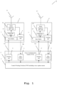
- the transmission system 1 comprises a Voice Communication Switch (VCS) 2 including a packing unit 4, 4' and a jitter buffer 5, 5'.
- the packing unit 4, 4' and the jitter buffer 5, 5' are connected to a Control Working Position (CWP) 3.
- Fig. 1 shows a ground radio station 6, 6' including a jitter buffer 7, 7', a delay line 12, 12', a radio frequency (RF) unit 10, 10', an antenna 11, 11' and a packing unit 8, 8'.
- Speech information from the air traffic controller is sent via the Control Working Position (CWP) to the packing unit 4, 4' in the Voice Communication Switch 2, converted into IP packets and transmitted over a Voice over IP network 9A, 9A' to the ground radio station 6, 6'.
- the transmitted IP packets are received and processed by the jitter buffer 7, 7' that converts the IP packets into a digital data stream that contains the speech information from the air traffic controller.
- each ground station provides a delay line 12, 12' that is connected to the output of the jitter buffer 7, 7'.
- the speech, respectively audio signal at the output of the jitter buffer 7, 7' is delayed via the delay line 12, 12' by a time Td1, Td1', which ensures that all ground stations start transmission at the same time or at least within a maximum defined delay.
- the radio frequency unit 10, 10' is connected to the output of the delay line 12, 12' and processes the received signals so that they are transmittable by the antenna 11, 11' and transmits the information via the antenna 11, 11' to the airplane.
- Speech information received by the antenna 11, 11' from the airplane is processed by the radio frequency unit 10, 10' to be usable by the packing unit 8, 8' that is connected to the output of the radio frequency unit 10, 10'.
- the packing unit 10, 10' generates IP packets from the received data and transmits the IP packets over the Voice over IP Network 9B, 9B' to the jitter buffer 5, 5' of the Voice Communication Switch 2.
- the jitter buffer 5, 5', that is connected to the Control Working Position 3 receives the IP packets sent over the network 9B, 9B', generates a digital data stream from the received data and sends the said digital data stream to the Control Working Position 3.
- the Control Working Position 3 processes the received data stream to a speech, respectively audio signal that can be made audible by a loud-speaker or headset so that the air traffic controller can hear the transmitted information from the pilot in the airplane. No time delays in ground-ground transmission for different ground radios have to be considered for the reception side, since only one of the incoming audio signals is delivered by the Control Working Position 3 to the controller headset or loud-speaker to avoid echos.
- Tdl, Td1' The determination of the delay time (Tdl, Tdl') is an easy task for a person skilled in the art and can for example be done with a vector network analysor a reflectometer or with an oscilloscope.
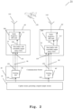
- Fig. 2 an embodiment of the transmission system 21 according to the first aspect of the invention is shown. Only the transmission path from capture means 30 to the transmitting ground radio station 60, 60', including the inventive solution to control the delay time (Tdl, Tdl') using a delay command is described, since the reception path from ground radio station to capture means is identical to the reception path already described in Fig. 1 , except that the data transmitted over the data packet transport network is available for, but not limited to internet protocol (IP) packets.
- IP internet protocol
- the transmission system 21 comprises capture means 30, connected to the input of a packing unit 40, 40' located in a communication switch 20.
- the capture means is configured to receive input signals, especially audio signals and/or video signals and to convert the said input signals into a digital sample stream 120, 120'.
- the transmission system 21 further comprises the packing unit 40, 40' that receives the digital data stream 120, 120' generated by the capture means 30.
- the packing unit 40, 40' generates data packets from the received digital data stream 120, 120', includes a delay command into at least one of the data packets and transmits the data packets 130, 130' over a packet transport network 90, 90' configured to provide data packet transmission between the communication switch 20 and at least one ground radio station 60, 60'.
- the delay command includes Global Positioning System (GPS) data of the object 150 that receives the transmission.
- GPS Global Positioning System
- the transmission system 21 comprises a ground radio station 60, 60' including a jitter buffer 70, 70' receiving the data packets 135, 135' from the communication switch 20 over the data packet transport network 90, 90'.
- a different referral number for the sent data packets 130, 130' and for the received data packets 135, 135' has been chosen to point out that the data packets are influenced during the transmission over the network 90, 90'.
- the jitter buffer 70, 70' is configured to convert the received data packets 135, 135' back into a digital data stream and to control the output timing of the said digital data stream depending on the delay command information included in at least one data packet.
- the jitter buffer 70, 70' outputs a digital data stream 140, 140' having a delay (Tdl, Tdl') based on the delay command.
- the ground radio station 60, 60' further includes a radio frequency unit 100, 100', wherein the jitter buffer 70, 70' is connected to the radio frequency unit 100, 100' input.
- Said radio frequency unit 100, 100' is configured to process the received delayed digital data stream 140, 140' such, that the data can be transmitted via the transmission antenna 110, 110'.
- the time delay generated by the jitter buffer 70, 70' based on the delay command is Td1, Td1'.
- the time delay between the output of the digital data stream 140, 140' of the jitter buffer 70, 70' and the output of the radio frequency unit 100, 100' to the antenna 110, 110' is denoted Ts1, Ts1' and is depending on the system properties of the radio frequency unit 100, 100'.
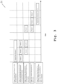
- Fig. 3 shows a diagram 31 to point out that a digital data stream 1, as depicted in line 1, is converted by the packing unit 40, 40' into several data packets (in this example into packets 1 to 3) and transmitted to the ground radio station, as shown and described in line 2.
- the data packets are transported via a data packet transport network.
- the said data packets are received by the ground radio station 60, 60' by the respective jitter buffer (70, 70') and do not necessarily arrive at the same order, as they have been transmitted, as shown in line 3.
- Transported data packets over a data packet transporting network may be subjected to a variety of impairments such as delay, delay variation and packet loss.
- the jitter buffer 40, 40' has to be configured to re-order the data packets before a digital data stream can be obtained from the data packets, as depicted in line 4.
- the functionality of a jitter buffer receiving data packets over a network is known to the person skilled in the art and therefore not described in detail.
- the drawing 31 further shows in line 5 that the digital data stream 1 is restored by the jitter buffer 70, 70' from the re-ordered data packets.
- the restored digital data stream is named digital data stream 1 (DS1).
- the restored digital data stream is made available at the output of the jitter buffer depending on the delay command information.
- the digital data stream 1 (DS1) is made available inside the jitter buffer 70, 70', exemplarily a ring buffer is conceivable to fulfill this task, and said data stream 1 (DS1) is sent to the radio frequency unit based on the delay command included into at least one data packet.
- the delay time Td1, Td1' can be adjusted.
- Fig. 4 an exemplary embodiment of the time delay adjustment depending on the delay command is shown.
- the digital data stream 1 (DS1) restored by the jitter buffer 70, 70' may be circulating in a ring buffer until the delay command triggers the output of the digital data stream 1 (DS1).
- DS1 digital data stream 1
- the digital data stream 1 (DS1) is circulating inside the ring buffer 41, 42, 43 and can be accessed by a pointer 44, pointing at the location of digital data stream (DS1) at a specific process step n or alternatively at a specific time point.
- the delay time Td1, Td1' of the restored digital data stream 1 (DS1) can be adjusted.
- the restored digital data stream (DS1) is accessed by the pointer 44, the information is made available at the jitter buffer output and can be received by the radio frequency unit 100, 100'.
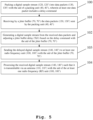
- a packing unit 40, 40' generates data packets 130, 130' from an incoming digital sample stream 120, 120', wherein at least one data packet includes a delay command.
- the delay command may be based on time information for sending a Request for Measurement Message and receiving a Measurement Answer Message and/or Global Positioning System (GPS) data of the communication object 150.
- GPS Global Positioning System
- the digital sample stream 120, 120' is preferably an audio data stream and/or a video data stream received by the packing unit 40, 40'.
- a jitter buffer 70, 70' is receiving the data packets 135, 135' sent by the packing unit 40, 40' .
- a third step 102 the jitter buffer 70, 70' processes the received data packets 135, 135' such that the digital sample stream 120, 120' fed into the packing unit 40, 40', converted into data packets and transmitted over the data packet transport network 90, 90', is restored. Since the incoming data packets 135, 135' are not always in the correct order and since some packets are delayed or do not even arrive at the jitter buffer 70, 70', said jitter buffer, as known to the person skilled in the art, brings the data packets into the correct order and provides feedback to the packet unit 40, 40', in case packages sent by the packing unit 40, 40', are not received, to control the re-sending of packets.
- the jitter buffer 70, 70' delays the output of the restored digital data stream by the time Td1, Td1', which allows to compensate for delay difference between all transmitting ground stations and ensures a simultaneous transmission of all transmitting ground stations.
- the delay time Td1, Td1' is determined based on the delay command, that is included in at least one data packet received by the jitter buffer 70, 70'.
- a fourth step 103 the jitter buffer 70, 70' sends the digital sample stream, delayed by the delay time Td1, Td1' to at least one radio frequency unit 100, 100'.
- the radio frequency unit 100, 100' processes the received delayed digital sample stream such, that it can be transmitted via an antenna 110, 110' to the object 150 to communicate with.
- the invention is not limited to the examples and especially not to specific types of devices under test.
- the characteristics of the exemplary embodiments can be used in any advantageous combination.
- the data packets preferably are IP (Internet Protocol) packets.
Landscapes
- Engineering & Computer Science (AREA)
- Computer Networks & Wireless Communication (AREA)
- Signal Processing (AREA)
- Mobile Radio Communication Systems (AREA)
Claims (12)
- Sprachübertragungssystem (21) mit Datenpakettransport und Verzögerungskompensation, das Folgendes umfasst:- eine Luftverkehrssteuerungsarbeitsposition, CWP, die ein Erfassungsmittel (30) umfasst,- einen Sprachkommunikationsschalter (20), der eine Packeinheit (40, 40') beinhaltet, die mit dem Erfassungsmittel (30) verbunden und dazu ausgelegt ist, einen digitalen Abtaststrom (120, 120') in Datenpakete (130, 130') umzuwandeln, und- eine Vielzahl von Bodenfunkstationen (60, 60'), die jeweils mindestens einen Jitterpuffer (70, 70') beinhalten, der die Datenpakete empfängt, die vom Kommunikationsschalter (20) übertragen werden, und jeweils mindestens eine Funkfrequenz(RF)-Einheit (100, 100') mit einer Antenne (110, 110') beinhalten,wobei mindestens ein Datenpaket (130, 130') einen Verzögerungsbefehl beinhaltet und wobei der Verzögerungsbefehl im Jitterpuffer (70, 70') verarbeitet wird, um eine Jitterpufferverzögerungszeit (Tdl) anzupassen,wobei der Verzögerungsbefehl auf Basis einer geschätzten Ende-zu-Ende-Datenverzögerung zwischen dem Erfassungsmittel (30) und dem Ausgang der Funkfrequenzeinheit (100, 100') berechnet wirdwobei das Erfassungsmittel (30) dazu ausgelegt ist, ein Eingangssignal in einen digitalen Abtaststrom (120, 120') umzuwandeln,wobei der Verzögerungsbefehl auf globalen Positionsbestimmungssystem(GPS)-Daten eines Objekts (150) basiert, das die Funkfrequenzübertragung der Funkfrequenzeinheit (100, 100') empfangen soll.
- System nach Anspruch 1,
wobei der Jitterpuffer (70, 70') dazu ausgelegt ist, die empfangenen Datenpakete in einen empfangenen digitalen Abtaststrom (140, 140') umzuwandeln. - System nach Anspruch 2,
wobei die Funkfrequenzeinheit (100, 100') den empfangenen digitalen Datenstrom (140, 140') in Signale umwandelt, die von der Antenne (110, 110') übertragbar sind. - System nach einem der Ansprüche 1 bis 3,
wobei das System ein Pakettransportnetzwerk (90, 90') umfasst, das dazu ausgelegt ist, zwischen dem Kommunikationsschalter (20) und mindestens einer Bodenfunkstation (60, 60') eine Datenpaketübertragung bereitzustellen. - System nach Anspruch 4,wobei das Pakettransportnetzwerk (90, 90') ein Internetprotokoll verwendet und/oderwobei der digitale Abtaststrom (120, 120') abgetastete Sprach- und/oder Videodaten umfasst.
- System nach einem der Ansprüche 1 bis 5,
wobei die Summe der Jitterpufferverzögerungszeit (Tdl, Tdl') und der Verzögerungszeit (Ts1, Ts1), die ein Signal zwischen dem Ausgang des Jitterpuffers (70, 70') und der Antenne (110, 110') erfährt, für jede Bodenfunkstation (60, 60') konstant ist. - Verfahren zur Sprachübertragung mit Datenpakettransport und Verzögerungskompensation zwischen einem Kommunikationsschalter und Bodenfunkstationen, wobei das Verfahren die folgenden Schritte umfasst:Packen eines digitalen Abtaststroms (120, 120') von einem Erfassungsmittel einer Luftverkehrssteuerungsarbeitsposition, CWP, (3) mithilfe einer Packeinheit (40, 40'), die sich in einem Kommunikationsschalter (20) befindet, via einen Sprachkommunikationsschalter in Datenpakete (130, 130'), wobei mindestens ein Datenpaket (130, 130') einen Verzögerungsbefehl beinhaltet, der auf Basis einer geschätzten Ende-zu-Ende-Datenverzögerung zwischen dem Erfassungsmittel (30) und dem Ausgang einer Funkfrequenzeinheit (100, 100') berechnet wird;Empfangen der Datenpakete (135, 135'), die von der Packeinheit (40, 40') gesendet werden, durch jeweils einen Jitterpuffer (70, 70'), die sich in mindestens zwei Bodenfunkstation (60, 60') befinden,Erzeugen eines digitalen Abtaststroms (140, 140') aus den empfangenen Datenpaketen (135, 135') und Anpassen einer Jitterpufferverzögerung (Tdl) mithilfe des Jitterpuffers (70, 70') auf Basis des Verzögerungsbefehls;Senden des verzögerten digitalen Abtaststroms mithilfe des Jitterpuffers (70, 70') an jeweils eine Funkfrequenz(RF)-Einheit (100, 100') undVerarbeiten des empfangenen digitalen Abtaststroms (140, 140') und Übertragen desselben über eine Antenne (110, 110') mithilfe der mindestens einen Funkfrequenz (RF) - Einheit (100, 100'),wobei der Verzögerungsbefehl auf globalen Positionsbestimmungssystem (GPS) -Daten eines Objekts (150) basiert, das die Funkfrequenzübertragung der Funkfrequenzeinheit (100, 100') empfangen soll.
- Verfahren nach Anspruch 7,
wobei das Verfahren ferner den Schritt des Umwandelns eines Eingangssignals mithilfe des Erfassungsmittels (30) in einen digitalen Abtaststrom (120, 120') umfasst. - Verfahren nach Anspruch 7 oder 8,
wobei das Verfahren ferner den Schritt des Auslegens eines Pakettransportnetzwerks (90, 90') umfasst, um zwischen einem Kommunikationsschalter (20) und mindestens einer Bodenfunkstation (60, 60') eine Datenpaketübertragung bereitzustellen. - Verfahren nach einem der Ansprüche 7 bis 9,
wobei das Verfahren ferner den Schritt des Übertragens einer Messanforderungsnachricht, RMM, mithilfe des Kommunikationsschalters (20) in regelmäßigen Intervallen zu allen Bodenfunkstationen (60, 60') umfasst. - Verfahren nach einem der Ansprüche 7 bis 10,
wobei das Verfahren ferner den Schritt des Antwortens mit einer Messantwortnachricht, MAM, an den Kommunikationsschalter (20) umfasst. - Verfahren nach einem der Ansprüche 7 bis 11,
wobei das Verfahren ferner den Schritt des Bestimmens des Verzögerungsbefehls auf Basis von Zeitinformationen zum Senden einer Messanforderungsnachricht und Empfangen einer Messantwortnachricht und/oder von GPS-Standortdaten des Kommunikationsobjekts (150) umfasst.
Applications Claiming Priority (1)
| Application Number | Priority Date | Filing Date | Title |
|---|---|---|---|
| EP17186793 | 2017-08-18 |
Publications (4)
| Publication Number | Publication Date |
|---|---|
| EP3444974A1 EP3444974A1 (de) | 2019-02-20 |
| EP3444974B1 EP3444974B1 (de) | 2022-06-29 |
| EP3444974B8 EP3444974B8 (de) | 2022-08-03 |
| EP3444974B2 true EP3444974B2 (de) | 2025-06-11 |
Family
ID=59686767
Family Applications (1)
| Application Number | Title | Priority Date | Filing Date |
|---|---|---|---|
| EP17195598.2A Active EP3444974B2 (de) | 2017-08-18 | 2017-10-10 | System und verfahren zur verzögerungskompensation für luftverkehrskontrolle |
Country Status (1)
| Country | Link |
|---|---|
| EP (1) | EP3444974B2 (de) |
Families Citing this family (2)
| Publication number | Priority date | Publication date | Assignee | Title |
|---|---|---|---|---|
| CN113271170B (zh) * | 2021-05-13 | 2022-04-29 | 哈尔滨工业大学 | 基于译码辅助的vlbi数据处理方法、装置及计算机存储介质 |
| CN113472612B (zh) * | 2021-08-31 | 2021-11-16 | 交通运输部规划研究院 | 一种无线电台的音频适配装置及其通信方法 |
Family Cites Families (4)
| Publication number | Priority date | Publication date | Assignee | Title |
|---|---|---|---|---|
| US7058568B1 (en) * | 2000-01-18 | 2006-06-06 | Cisco Technology, Inc. | Voice quality improvement for voip connections on low loss network |
| SE0004839D0 (sv) * | 2000-12-22 | 2000-12-22 | Ericsson Telefon Ab L M | Method and communication apparatus in a communication system |
| US8085678B2 (en) | 2004-10-13 | 2011-12-27 | Qualcomm Incorporated | Media (voice) playback (de-jitter) buffer adjustments based on air interface |
| US8194544B2 (en) * | 2006-11-22 | 2012-06-05 | Belair Networks Inc. | Network delay shaping system and method for backhaul of wireless networks |
-
2017
- 2017-10-10 EP EP17195598.2A patent/EP3444974B2/de active Active
Also Published As
| Publication number | Publication date |
|---|---|
| EP3444974B1 (de) | 2022-06-29 |
| EP3444974B8 (de) | 2022-08-03 |
| EP3444974A1 (de) | 2019-02-20 |
Similar Documents
| Publication | Publication Date | Title |
|---|---|---|
| CN108964739B (zh) | 用于多信道交通工具通信的系统和方法 | |
| US8675635B2 (en) | Master terminal synchronization for mesh satellite communications | |
| CN107548567B (zh) | 在电信系统中同步多输入/多输出信号 | |
| EP1107484A1 (de) | Mobiles kommunikationssystem | |
| EP3579458A1 (de) | System zum synchronisieren eines bodensegments mit einem strahlsprungsatelliten | |
| CN111373691A (zh) | 分布式天线系统中的同步与故障管理 | |
| US8086249B1 (en) | Ranging of wireless communication networks with distant wireless links | |
| US8054822B2 (en) | Synchronization of call traffic in the forward direction over backhaul links | |
| WO2021011147A3 (en) | Assisting communications of small data payloads with relay nodes | |
| EP3444974B1 (de) | System und verfahren zur verzögerungskompensation für luftverkehrskontrolle | |
| IL259363A (en) | Method and system for managing protocol for routing communication between satellite transmitters | |
| CN101124742A (zh) | 用于具有卫星回程链路的地面无线通信系统的定时补偿方法和装置 | |
| GB2321829A (en) | Time Delay Control of Frame Synchronous Signal | |
| JP7721687B2 (ja) | Ipベースネットワーク上の音声コンテンツの受信中のジッタ補償の方法並びにそのための受信器、並びにジッタ補償を有する音声コンテンツを送受信するための方法及びデバイス | |
| CN111970290B (zh) | 一种基于VoIP地空语音通信的多载波延时补偿方法 | |
| JP5636558B2 (ja) | ネットワーク装置、及び、通信方法 | |
| JP4651364B2 (ja) | 位相調整方法及び装置 | |
| CN109818699B (zh) | 用于在飞行器中广播时间基准的系统 | |
| JP5143624B2 (ja) | 非同期ネットワークを用いた電波送信システム及び電波同期送信方法 | |
| US20250317875A1 (en) | Control device, base station, and control method | |
| US8228957B1 (en) | Differential delay mitigation in diverse backhaul environments | |
| JP6763735B2 (ja) | デジタル無線システム | |
| JP2024009627A (ja) | 非静止衛星通信システム、非衛星通信システムにおける通信遅延を調整する調整装置及びプログラム | |
| JP2013066009A (ja) | エリア拡張システムとそのエリア拡張装置及びエリア拡張通信方法 | |
| JP2019062368A (ja) | 基地局装置、送信方法、プログラム |
Legal Events
| Date | Code | Title | Description |
|---|---|---|---|
| PUAI | Public reference made under article 153(3) epc to a published international application that has entered the european phase |
Free format text: ORIGINAL CODE: 0009012 |
|
| STAA | Information on the status of an ep patent application or granted ep patent |
Free format text: STATUS: REQUEST FOR EXAMINATION WAS MADE |
|
| 17P | Request for examination filed |
Effective date: 20180914 |
|
| AK | Designated contracting states |
Kind code of ref document: A1 Designated state(s): AL AT BE BG CH CY CZ DE DK EE ES FI FR GB GR HR HU IE IS IT LI LT LU LV MC MK MT NL NO PL PT RO RS SE SI SK SM TR |
|
| AX | Request for extension of the european patent |
Extension state: BA ME |
|
| RIN1 | Information on inventor provided before grant (corrected) |
Inventor name: TURLEA, CRISTIAN Inventor name: PATRU, EUGEN Inventor name: ZAHARIA, NICOLAE Inventor name: BICA, DUMITRU |
|
| STAA | Information on the status of an ep patent application or granted ep patent |
Free format text: STATUS: EXAMINATION IS IN PROGRESS |
|
| 17Q | First examination report despatched |
Effective date: 20200421 |
|
| REG | Reference to a national code |
Ref country code: DE Ref legal event code: R079 Ref document number: 602017058957 Country of ref document: DE Free format text: PREVIOUS MAIN CLASS: H04J0003060000 Ipc: H04L0047300000 |
|
| GRAP | Despatch of communication of intention to grant a patent |
Free format text: ORIGINAL CODE: EPIDOSNIGR1 |
|
| STAA | Information on the status of an ep patent application or granted ep patent |
Free format text: STATUS: GRANT OF PATENT IS INTENDED |
|
| RIC1 | Information provided on ipc code assigned before grant |
Ipc: H04J 3/06 20060101ALI20220324BHEP Ipc: H04L 47/22 20220101ALI20220324BHEP Ipc: H04L 47/30 20220101AFI20220324BHEP |
|
| GRAS | Grant fee paid |
Free format text: ORIGINAL CODE: EPIDOSNIGR3 |
|
| INTG | Intention to grant announced |
Effective date: 20220419 |
|
| GRAA | (expected) grant |
Free format text: ORIGINAL CODE: 0009210 |
|
| STAA | Information on the status of an ep patent application or granted ep patent |
Free format text: STATUS: THE PATENT HAS BEEN GRANTED |
|
| AK | Designated contracting states |
Kind code of ref document: B1 Designated state(s): AL AT BE BG CH CY CZ DE DK EE ES FI FR GB GR HR HU IE IS IT LI LT LU LV MC MK MT NL NO PL PT RO RS SE SI SK SM TR |
|
| REG | Reference to a national code |
Ref country code: AT Ref legal event code: REF Ref document number: 1502050 Country of ref document: AT Kind code of ref document: T Effective date: 20220715 |
|
| RBV | Designated contracting states (corrected) |
Designated state(s): AL AT BE BG CY CZ DE DK EE ES FI FR GB GR HR HU IS IT LT LU LV MC MK MT NL NO PL PT RO RS SE SI SK SM TR |
|
| REG | Reference to a national code |
Ref country code: IE Ref legal event code: FG4D |
|
| REG | Reference to a national code |
Ref country code: DE Ref legal event code: R096 Ref document number: 602017058957 Country of ref document: DE |
|
| REG | Reference to a national code |
Ref country code: LT Ref legal event code: MG9D |
|
| PG25 | Lapsed in a contracting state [announced via postgrant information from national office to epo] |
Ref country code: SE Free format text: LAPSE BECAUSE OF FAILURE TO SUBMIT A TRANSLATION OF THE DESCRIPTION OR TO PAY THE FEE WITHIN THE PRESCRIBED TIME-LIMIT Effective date: 20220629 Ref country code: NO Free format text: LAPSE BECAUSE OF FAILURE TO SUBMIT A TRANSLATION OF THE DESCRIPTION OR TO PAY THE FEE WITHIN THE PRESCRIBED TIME-LIMIT Effective date: 20220929 Ref country code: LT Free format text: LAPSE BECAUSE OF FAILURE TO SUBMIT A TRANSLATION OF THE DESCRIPTION OR TO PAY THE FEE WITHIN THE PRESCRIBED TIME-LIMIT Effective date: 20220629 Ref country code: HR Free format text: LAPSE BECAUSE OF FAILURE TO SUBMIT A TRANSLATION OF THE DESCRIPTION OR TO PAY THE FEE WITHIN THE PRESCRIBED TIME-LIMIT Effective date: 20220629 Ref country code: GR Free format text: LAPSE BECAUSE OF FAILURE TO SUBMIT A TRANSLATION OF THE DESCRIPTION OR TO PAY THE FEE WITHIN THE PRESCRIBED TIME-LIMIT Effective date: 20220930 Ref country code: FI Free format text: LAPSE BECAUSE OF FAILURE TO SUBMIT A TRANSLATION OF THE DESCRIPTION OR TO PAY THE FEE WITHIN THE PRESCRIBED TIME-LIMIT Effective date: 20220629 Ref country code: BG Free format text: LAPSE BECAUSE OF FAILURE TO SUBMIT A TRANSLATION OF THE DESCRIPTION OR TO PAY THE FEE WITHIN THE PRESCRIBED TIME-LIMIT Effective date: 20220929 |
|
| REG | Reference to a national code |
Ref country code: NL Ref legal event code: MP Effective date: 20220629 |
|
| REG | Reference to a national code |
Ref country code: AT Ref legal event code: MK05 Ref document number: 1502050 Country of ref document: AT Kind code of ref document: T Effective date: 20220629 |
|
| PG25 | Lapsed in a contracting state [announced via postgrant information from national office to epo] |
Ref country code: RS Free format text: LAPSE BECAUSE OF FAILURE TO SUBMIT A TRANSLATION OF THE DESCRIPTION OR TO PAY THE FEE WITHIN THE PRESCRIBED TIME-LIMIT Effective date: 20220629 Ref country code: LV Free format text: LAPSE BECAUSE OF FAILURE TO SUBMIT A TRANSLATION OF THE DESCRIPTION OR TO PAY THE FEE WITHIN THE PRESCRIBED TIME-LIMIT Effective date: 20220629 |
|
| PG25 | Lapsed in a contracting state [announced via postgrant information from national office to epo] |
Ref country code: NL Free format text: LAPSE BECAUSE OF FAILURE TO SUBMIT A TRANSLATION OF THE DESCRIPTION OR TO PAY THE FEE WITHIN THE PRESCRIBED TIME-LIMIT Effective date: 20220629 |
|
| PG25 | Lapsed in a contracting state [announced via postgrant information from national office to epo] |
Ref country code: SM Free format text: LAPSE BECAUSE OF FAILURE TO SUBMIT A TRANSLATION OF THE DESCRIPTION OR TO PAY THE FEE WITHIN THE PRESCRIBED TIME-LIMIT Effective date: 20220629 Ref country code: SK Free format text: LAPSE BECAUSE OF FAILURE TO SUBMIT A TRANSLATION OF THE DESCRIPTION OR TO PAY THE FEE WITHIN THE PRESCRIBED TIME-LIMIT Effective date: 20220629 Ref country code: RO Free format text: LAPSE BECAUSE OF FAILURE TO SUBMIT A TRANSLATION OF THE DESCRIPTION OR TO PAY THE FEE WITHIN THE PRESCRIBED TIME-LIMIT Effective date: 20220629 Ref country code: PT Free format text: LAPSE BECAUSE OF FAILURE TO SUBMIT A TRANSLATION OF THE DESCRIPTION OR TO PAY THE FEE WITHIN THE PRESCRIBED TIME-LIMIT Effective date: 20221031 Ref country code: ES Free format text: LAPSE BECAUSE OF FAILURE TO SUBMIT A TRANSLATION OF THE DESCRIPTION OR TO PAY THE FEE WITHIN THE PRESCRIBED TIME-LIMIT Effective date: 20220629 Ref country code: EE Free format text: LAPSE BECAUSE OF FAILURE TO SUBMIT A TRANSLATION OF THE DESCRIPTION OR TO PAY THE FEE WITHIN THE PRESCRIBED TIME-LIMIT Effective date: 20220629 Ref country code: AT Free format text: LAPSE BECAUSE OF FAILURE TO SUBMIT A TRANSLATION OF THE DESCRIPTION OR TO PAY THE FEE WITHIN THE PRESCRIBED TIME-LIMIT Effective date: 20220629 |
|
| PG25 | Lapsed in a contracting state [announced via postgrant information from national office to epo] |
Ref country code: PL Free format text: LAPSE BECAUSE OF FAILURE TO SUBMIT A TRANSLATION OF THE DESCRIPTION OR TO PAY THE FEE WITHIN THE PRESCRIBED TIME-LIMIT Effective date: 20220629 Ref country code: IS Free format text: LAPSE BECAUSE OF FAILURE TO SUBMIT A TRANSLATION OF THE DESCRIPTION OR TO PAY THE FEE WITHIN THE PRESCRIBED TIME-LIMIT Effective date: 20221029 |
|
| REG | Reference to a national code |
Ref country code: DE Ref legal event code: R026 Ref document number: 602017058957 Country of ref document: DE |
|
| PG25 | Lapsed in a contracting state [announced via postgrant information from national office to epo] |
Ref country code: AL Free format text: LAPSE BECAUSE OF FAILURE TO SUBMIT A TRANSLATION OF THE DESCRIPTION OR TO PAY THE FEE WITHIN THE PRESCRIBED TIME-LIMIT Effective date: 20220629 |
|
| PLBI | Opposition filed |
Free format text: ORIGINAL CODE: 0009260 |
|
| PLAX | Notice of opposition and request to file observation + time limit sent |
Free format text: ORIGINAL CODE: EPIDOSNOBS2 |
|
| PG25 | Lapsed in a contracting state [announced via postgrant information from national office to epo] |
Ref country code: DK Free format text: LAPSE BECAUSE OF FAILURE TO SUBMIT A TRANSLATION OF THE DESCRIPTION OR TO PAY THE FEE WITHIN THE PRESCRIBED TIME-LIMIT Effective date: 20220629 Ref country code: CZ Free format text: LAPSE BECAUSE OF FAILURE TO SUBMIT A TRANSLATION OF THE DESCRIPTION OR TO PAY THE FEE WITHIN THE PRESCRIBED TIME-LIMIT Effective date: 20220629 |
|
| 26 | Opposition filed |
Opponent name: FREQUENTIS AG Effective date: 20230328 |
|
| PG25 | Lapsed in a contracting state [announced via postgrant information from national office to epo] |
Ref country code: MC Free format text: LAPSE BECAUSE OF FAILURE TO SUBMIT A TRANSLATION OF THE DESCRIPTION OR TO PAY THE FEE WITHIN THE PRESCRIBED TIME-LIMIT Effective date: 20220629 |
|
| REG | Reference to a national code |
Ref country code: BE Ref legal event code: MM Effective date: 20221031 |
|
| PG25 | Lapsed in a contracting state [announced via postgrant information from national office to epo] |
Ref country code: LU Free format text: LAPSE BECAUSE OF NON-PAYMENT OF DUE FEES Effective date: 20221010 |
|
| P01 | Opt-out of the competence of the unified patent court (upc) registered |
Effective date: 20230525 |
|
| PLBB | Reply of patent proprietor to notice(s) of opposition received |
Free format text: ORIGINAL CODE: EPIDOSNOBS3 |
|
| PG25 | Lapsed in a contracting state [announced via postgrant information from national office to epo] |
Ref country code: SI Free format text: LAPSE BECAUSE OF FAILURE TO SUBMIT A TRANSLATION OF THE DESCRIPTION OR TO PAY THE FEE WITHIN THE PRESCRIBED TIME-LIMIT Effective date: 20220629 |
|
| PG25 | Lapsed in a contracting state [announced via postgrant information from national office to epo] |
Ref country code: BE Free format text: LAPSE BECAUSE OF NON-PAYMENT OF DUE FEES Effective date: 20221031 |
|
| PG25 | Lapsed in a contracting state [announced via postgrant information from national office to epo] |
Ref country code: IT Free format text: LAPSE BECAUSE OF FAILURE TO SUBMIT A TRANSLATION OF THE DESCRIPTION OR TO PAY THE FEE WITHIN THE PRESCRIBED TIME-LIMIT Effective date: 20220629 |
|
| PG25 | Lapsed in a contracting state [announced via postgrant information from national office to epo] |
Ref country code: HU Free format text: LAPSE BECAUSE OF FAILURE TO SUBMIT A TRANSLATION OF THE DESCRIPTION OR TO PAY THE FEE WITHIN THE PRESCRIBED TIME-LIMIT; INVALID AB INITIO Effective date: 20171010 |
|
| PG25 | Lapsed in a contracting state [announced via postgrant information from national office to epo] |
Ref country code: CY Free format text: LAPSE BECAUSE OF FAILURE TO SUBMIT A TRANSLATION OF THE DESCRIPTION OR TO PAY THE FEE WITHIN THE PRESCRIBED TIME-LIMIT Effective date: 20220629 |
|
| PG25 | Lapsed in a contracting state [announced via postgrant information from national office to epo] |
Ref country code: MK Free format text: LAPSE BECAUSE OF FAILURE TO SUBMIT A TRANSLATION OF THE DESCRIPTION OR TO PAY THE FEE WITHIN THE PRESCRIBED TIME-LIMIT Effective date: 20220629 |
|
| PG25 | Lapsed in a contracting state [announced via postgrant information from national office to epo] |
Ref country code: MT Free format text: LAPSE BECAUSE OF FAILURE TO SUBMIT A TRANSLATION OF THE DESCRIPTION OR TO PAY THE FEE WITHIN THE PRESCRIBED TIME-LIMIT Effective date: 20220629 |
|
| PG25 | Lapsed in a contracting state [announced via postgrant information from national office to epo] |
Ref country code: BG Free format text: LAPSE BECAUSE OF FAILURE TO SUBMIT A TRANSLATION OF THE DESCRIPTION OR TO PAY THE FEE WITHIN THE PRESCRIBED TIME-LIMIT Effective date: 20220629 |
|
| PG25 | Lapsed in a contracting state [announced via postgrant information from national office to epo] |
Ref country code: BG Free format text: LAPSE BECAUSE OF FAILURE TO SUBMIT A TRANSLATION OF THE DESCRIPTION OR TO PAY THE FEE WITHIN THE PRESCRIBED TIME-LIMIT Effective date: 20220629 |
|
| PUAH | Patent maintained in amended form |
Free format text: ORIGINAL CODE: 0009272 |
|
| STAA | Information on the status of an ep patent application or granted ep patent |
Free format text: STATUS: PATENT MAINTAINED AS AMENDED |
|
| 27A | Patent maintained in amended form |
Effective date: 20250611 |
|
| AK | Designated contracting states |
Kind code of ref document: B2 Designated state(s): AL AT BE BG CY CZ DE DK EE ES FI FR GB GR HR HU IS IT LT LU LV MC MK MT NL NO PL PT RO RS SE SI SK SM TR |
|
| REG | Reference to a national code |
Ref country code: DE Ref legal event code: R102 Ref document number: 602017058957 Country of ref document: DE |
|
| PG25 | Lapsed in a contracting state [announced via postgrant information from national office to epo] |
Ref country code: TR Free format text: LAPSE BECAUSE OF FAILURE TO SUBMIT A TRANSLATION OF THE DESCRIPTION OR TO PAY THE FEE WITHIN THE PRESCRIBED TIME-LIMIT Effective date: 20220629 |
|
| PGFP | Annual fee paid to national office [announced via postgrant information from national office to epo] |
Ref country code: DE Payment date: 20251020 Year of fee payment: 9 |
|
| PGFP | Annual fee paid to national office [announced via postgrant information from national office to epo] |
Ref country code: GB Payment date: 20251024 Year of fee payment: 9 |
|
| PGFP | Annual fee paid to national office [announced via postgrant information from national office to epo] |
Ref country code: FR Payment date: 20251022 Year of fee payment: 9 |