EP3444910A1 - Cable insertion tool - Google Patents
Cable insertion tool Download PDFInfo
- Publication number
- EP3444910A1 EP3444910A1 EP17186958.9A EP17186958A EP3444910A1 EP 3444910 A1 EP3444910 A1 EP 3444910A1 EP 17186958 A EP17186958 A EP 17186958A EP 3444910 A1 EP3444910 A1 EP 3444910A1
- Authority
- EP
- European Patent Office
- Prior art keywords
- corner
- insertion tool
- cable insertion
- slashed
- corrugated pipe
- Prior art date
- Legal status (The legal status is an assumption and is not a legal conclusion. Google has not performed a legal analysis and makes no representation as to the accuracy of the status listed.)
- Granted
Links
Images

Classifications
-
- H—ELECTRICITY
- H02—GENERATION; CONVERSION OR DISTRIBUTION OF ELECTRIC POWER
- H02G—INSTALLATION OF ELECTRIC CABLES OR LINES, OR OF COMBINED OPTICAL AND ELECTRIC CABLES OR LINES
- H02G1/00—Methods or apparatus specially adapted for installing, maintaining, repairing or dismantling electric cables or lines
- H02G1/06—Methods or apparatus specially adapted for installing, maintaining, repairing or dismantling electric cables or lines for laying cables, e.g. laying apparatus on vehicle
- H02G1/08—Methods or apparatus specially adapted for installing, maintaining, repairing or dismantling electric cables or lines for laying cables, e.g. laying apparatus on vehicle through tubing or conduit, e.g. rod or draw wire for pushing or pulling
- H02G1/085—Methods or apparatus specially adapted for installing, maintaining, repairing or dismantling electric cables or lines for laying cables, e.g. laying apparatus on vehicle through tubing or conduit, e.g. rod or draw wire for pushing or pulling using portable tools
Definitions
- the present invention relates to a cable insertion tool for supporting manually insertion of at least one electrical cable into a slashed corrugated pipe.
- Document DE10134570 discloses an application whereby an optical fiber is inserted into a slashed corrugated pipe with the help of a tool.
- the tool extends the longitudinal slot in the tube in an amount that the fiber can pass the slot and move to inside the slashed corrugated pipe.
- slashed corrugated pipes known as Monoflex slashed corrugated pipes
- Monoflex slashed corrugated pipes provide this increased requirements for slashed corrugated pipes.
- the improved properties of the slashed corrugated pipes have on the other hand disadvantages that pop up while assembling the wiring harness.
- the Monoflex slashed corrugated pipes are harder than previously used tubes. Because of the big hardness of Monoflex tubes the tool life time is significantly decreased. While increasing the slot of the slashed corrugated pipe, the slashed corrugated pipe acts like a spring and tries to close the increased slot. A high spring force is generated while spreading the slashed corrugated pipe to feed in the wire.
- the present invention improves the state of the art by providing a cable insertion tool that is usable for hard, state of the art slashed corrugated pipes, thereby protecting the wires of the cable while operating the cable insertion tool and having improved lifetime.
- the present application relates to a cable insertion tool for supporting manually insertion of at least one electrical cable into a slashed corrugated pipe.
- the insertion tool comprises, a body formed by bending a quadrilateral sheet around an inlet axis defining an arc, having a first radius.
- the body has a u-shaped cross section perpendicular to the inlet axis and an outer surface.
- the quadrilateral sheet comprises a first corner a third corner located opposite the first corner, a body edge starting from a second corner continuing to the third corner and further to a fourth corner.
- the inlet axis extends from the first corner towards the third corner.
- the inlet axis is angled with respect to a plane spanned by the body edge between the third corner and the second corner and the third corner and the fourth corner.
- a first guiding rib extends from the body edge outwards.
- a support means supporting the widening of a slot of the slashed corrugated pipe by urging against the inner surface of the slashed corrugated pipe, when the tool is positioned to be pulled along the slashed corrugated pipe.
- the disclosed invention provides a cable insertion tool for usage in wiring application using robust slashed corrugated pipes to protect the electrical cable.
- the cable insertion tool has support means that reduce the high unwanted, forces that press the edges against the tool.
- the support means widen the slot to a certain amount by urging against the inner wall of the slashed corrugated pipe. A part of the generated spring force is taken over by the support means. The remaining spring force acting on the edges is not high enough to wear out the cable insertion tool in short time.
- quadrilateral is referenced to Euclidean plane geometry, a quadrilateral is a polygon with four edges (or sides) and four vertices or corners.
- the first guiding rib comprises a protection tongue protruding outwards, from the third corner defining an angle to the outer surface.
- the protection tongue extends most preferred along the extension of the slashed corrugated pipe.
- the protection tongue keeps the wires of the cable inside the slashed corrugated pipe, while the slot is decreasing, after the tool is moved further, after insertion of the wires.
- the protection tongue covers the slot from the inside of the slashed corrugated pipe until the slot has its relaxed size.
- the body comprises an inner surface free from irregularities.
- a smooth inner surface makes the tool easy to produce and also easy to operate in the production plant.
- the body edge is curved inwards the body between the third corner and the second corner and between the third corner and the fourth corner.
- the body edge can be curved along the extension axis of the slashed corrugated pipe.
- the first guiding rib follows the curved design. The waved guiding rib pulls out the slashed corrugated pipe a little and takes also some spring force from the edges.
- the body comprises a handle attached on the outer surface of the body between the first corner and the second corner or between the first corner and the fourth corner.
- the handle is arranged on the body on the side where the cable insertion tool is first inserted into the slot of the slashed corrugated pipe. The cable insertion tool will be than pulled along the slashed corrugated pipe, while holding it on the handle.
- the body is mirror symmetrical with respect to the inlet axis.
- symmetrical body promises a well working cable insertion tool.
- An unsymmetrical embodiment is also possible for special application.
- the body allows flexible deformation when the second corner is moved towards the fourth corner.
- the second corner and the fourth corner are in touch. After usage the cable insertion tool relaxes again to its relaxed shape. There are no hinges necessary to operate the cable insertion tool.
- the first guiding rib extends from the second corner to the fourth corner and whereby a second guiding rib extends parallel shifted along the inlet axis from an outer surface of the body.
- a second guiding rib parallel to the first guiding rib defines a guiding groove that guides the cable insertion tool, taking the wall of the slashed corrugated pipe as a guiding rail. That design improves the handling while assembling in the harness manufacturing plant.
- the support means comprise a guiding fin arranged between the third corner and the second corner protruding outwardly from the body.
- the guiding fin can protrude from the outer surface or from the body edge or where suitable.
- the guiding fin protrudes flexible against the inner wall of the slashed corrugated pipe and provides this way the additionally force to widen the slot of the slashed corrugated pipe.
- the guiding fin is L-shaped or curved, comprising a base fin portion mechanically connected to the body.
- the guiding fin can be shaped in any possible way if it improves the technical function.
- the mentioned embodiments promise a good combination of rigidity and flexibility.
- the guiding fin comprises a cable slide surface arranged opposite to the slide fin portion.
- the function of the guiding fin can be increased by using the wire cable as support for the guiding fin. This design enables the guiding fin to push harder against the inner surface because flexing towards the wire cable is not possible.
- the base fin portion comprises at least one sound rib protruding from the base fin portion adapted to stay away from the corrugations of the slashed corrugated pipe while the cable insertion tool is moved along the slashed corrugated pipe and wherein the at least one sound rib hit against the corrugations of the slashed corrugated pipe when the cable insertion tool is used in a misaligned position thereby generating a sound.
- manufacturing in the harness plant audible and a haptic feedback is important for producing constant quality. Misalignments of the cable insertion tool are immediately detectable. Correct usage of the cable insertion tool reduces also faster wear out of the cable insertion tool.
- the guiding fin extends from the body edge defining an angle of more than 45° and less than 180° with respect to the outer surface.
- the guiding fin can be arranged in various angles and is adaptable to a variety of requirements, depending on size and material of the slashed corrugated pipe.
- the body is made from one piece.
- the cable insertion tool can be made from one piece for example from a sheet metal or by injection molding from plastics.
- the body is made of plastics.
- a body made of plastics is easy and cheap to produce.
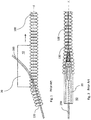
- Figure 1 shows a side view and figure 2 shows a top view of a cable insertion tool 10 known in the art, while inserting an electrical cable 200 into a slashed corrugated pipe 100.
- the cable insertion tool 10 is already inserted into the slot 110 of the slashed corrugated pipe 100.
- the body 20 of the cable insertion tool 10 is all moved along a longitudinal axis X of the slashed corrugated pipe 100, thereby widening the slot 110 of the slashed corrugated pipe 100.
- the electrical cable 200 is guided through the expanded slot 110 into the inside 120 of the slashed corrugated pipe 100.
- the slot 110 is only expanded at the position where the cable insertion tool 10 his present. When the cable insertion tool 10 is moved further along the longitudinal axis X of the slashed corrugated pipe 100, the expanded slot 110 relaxes and the slot wide decreases.
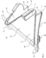
- FIG. 3 shows a cable insertion tool 10 for supporting manually insertion of at least one electrical cable 200 into a slashed corrugated pipe 100.
- the insertion tool 10 comprises, a body 20 formed by bending a quadrilateral sheet around an inlet axis I defining an arc, having a first radius 32.
- the body 20 has a u-shaped cross section perpendicular to the inlet axis I and an outer surface 21.
- the quadrilateral sheet comprises a first corner 24, a third corner 28 located opposite the first corner, a body edge 40 starting from a second corner 26 continuing to the third corner 28 and further to a fourth corner 30.
- the inlet axis I extends from the first corner 24 towards the third corner 28.
- the inlet axis I is angled with respect to a plane spanned by the body edge 40 between the third corner 28 and the second corner 26 and the third corner and the fourth corner 30, a first guiding rib 42 extends from the body edge 40 outwards, a support means, supporting the widening of a slot 110 of the slashed corrugated pipe 100 by urging against the inner surface of the slashed corrugated pipe 100, when the tool is positioned to be pulled along the slashed corrugated pipe 100.
- the first guiding rib 42 comprises a protection tongue 50 protruding outwards, from the third corner 28 defining an angle to the outer surface 21.
- the Protection tongue 50 protrudes parallel the longitudinal axis X of the slashed corrugated pipe 100.
- the body 20 comprises an inner surface 22, free from irregularities.
- the inner surface 22 surrounds the at least one electrical cable 200 while the insertion process. Because the inner surface 22 is smooth the at least one electrical cable 200 can move through the cable insertion tool 10 quite easy.
- the body 20 comprises a handle 70 attached on the outer surface 21 of the body 20 between the first corner 24 and the second corner 26 or between the first corner 24 and the fourth corner 30.
- the body 20 is mirror symmetrical with respect to the inlet axis I.
- the first guiding rib 42 extends from the second corner 26 to the fourth corner 30 and whereby a second guiding rib 44 extends parallel shifted along the inlet axis I from an outer surface 21 of the body 20.
- the support means comprise a guiding fin 60, arranged between the third corner 28 and the second corner 26 protruding outwardly from the body 20.
- FIG. 4 shows a detailed view of the support means of the cable insertion tool.
- the guiding fin 60 is L-shaped or curved, comprising a base fin portion 62 mechanically connected to the body edge 40 and a slide fin portion 64 having a free end protruding from the base fin portion 62.
- the guiding fin 60 comprises a cable slide surface 68 arranged opposite to the slide fin portion 64.
- the base fin portion 62 comprises at least one sound rib 66, protruding from the base fin portion 62 adapted to stay away from the corrugations of the slashed corrugated pipe 100 while the cable insertion tool 10 is moved along the slashed corrugated pipe 100 and wherein the at least one sound rib 66 hit against the corrugations of the slashed corrugated pipe 100 when the cable insertion tool 10 is used in a misaligned position thereby generating a sound.
- the guiding fin 60 extends from the body edge 40 defining an angle of more than 45° and less than 180° with respect to the outer surface 21.
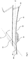
- Figure 5 shows a side view of the cable insertion tool, focusing on the area around the body edge 40.
- the body edge 40 is curved inwards the body 20 between the third corner 28 and the second corner 26 and between the third corner and the fourth corner 30.
Landscapes
- Electric Cable Arrangement Between Relatively Moving Parts (AREA)
Abstract
Description
- The present invention relates to a cable insertion tool for supporting manually insertion of at least one electrical cable into a slashed corrugated pipe.
- The technique to protect electrical cable from damages by insertion of electrical cable into a slashed corrugated pipe it is well known in the art. Document
DE10134570 discloses an application whereby an optical fiber is inserted into a slashed corrugated pipe with the help of a tool. The tool extends the longitudinal slot in the tube in an amount that the fiber can pass the slot and move to inside the slashed corrugated pipe. But over the time the requirements, concerning environmental temperatures and robustness of the wiring harnesses increased. This made it necessary to use improved materials for insulation of the cables and also for the slashed corrugated pipe surrounding the cables. State of the art slashed corrugated pipes, known as Monoflex slashed corrugated pipes, provide this increased requirements for slashed corrugated pipes. But the improved properties of the slashed corrugated pipes have on the other hand disadvantages that pop up while assembling the wiring harness. The Monoflex slashed corrugated pipes are harder than previously used tubes. Because of the big hardness of Monoflex tubes the tool life time is significantly decreased. While increasing the slot of the slashed corrugated pipe, the slashed corrugated pipe acts like a spring and tries to close the increased slot. A high spring force is generated while spreading the slashed corrugated pipe to feed in the wire. This results in that the sharp edges of the slot are pressed hard against everything that is in between the edges of the slot. An accidentally protruding wire can be damaged or cut by the edges. Insertion tools known in the art have to resist the sharp edges pressed towards the tool, which causes increased wear of the tool. Worn tools can also damage wires during assembly. As result any derailing (situation when tube fall from tool during assembly) can easy lead to cutting wires. - Therefore, in one aspect, the present invention improves the state of the art by providing a cable insertion tool that is usable for hard, state of the art slashed corrugated pipes, thereby protecting the wires of the cable while operating the cable insertion tool and having improved lifetime.
- These and other objects which become apparent upon reading the following description are solved by a cable insertion tool according to independent claim 1.
- The present application relates to a cable insertion tool for supporting manually insertion of at least one electrical cable into a slashed corrugated pipe. The insertion tool comprises, a body formed by bending a quadrilateral sheet around an inlet axis defining an arc, having a first radius. The body has a u-shaped cross section perpendicular to the inlet axis and an outer surface. The quadrilateral sheet comprises a first corner a third corner located opposite the first corner, a body edge starting from a second corner continuing to the third corner and further to a fourth corner. The inlet axis extends from the first corner towards the third corner. The inlet axis is angled with respect to a plane spanned by the body edge between the third corner and the second corner and the third corner and the fourth corner. A first guiding rib extends from the body edge outwards. A support means, supporting the widening of a slot of the slashed corrugated pipe by urging against the inner surface of the slashed corrugated pipe, when the tool is positioned to be pulled along the slashed corrugated pipe.
- The disclosed invention provides a cable insertion tool for usage in wiring application using robust slashed corrugated pipes to protect the electrical cable. The cable insertion tool has support means that reduce the high unwanted, forces that press the edges against the tool. The support means widen the slot to a certain amount by urging against the inner wall of the slashed corrugated pipe. A part of the generated spring force is taken over by the support means. The remaining spring force acting on the edges is not high enough to wear out the cable insertion tool in short time.
- The term quadrilateral is referenced to Euclidean plane geometry, a quadrilateral is a polygon with four edges (or sides) and four vertices or corners.
- According to a preferred embodiment the first guiding rib comprises a protection tongue protruding outwards, from the third corner defining an angle to the outer surface. The protection tongue extends most preferred along the extension of the slashed corrugated pipe. The protection tongue keeps the wires of the cable inside the slashed corrugated pipe, while the slot is decreasing, after the tool is moved further, after insertion of the wires. The protection tongue covers the slot from the inside of the slashed corrugated pipe until the slot has its relaxed size.
- Preferably the body comprises an inner surface free from irregularities. A smooth inner surface makes the tool easy to produce and also easy to operate in the production plant.
- Advantageously, the body edge is curved inwards the body between the third corner and the second corner and between the third corner and the fourth corner. The body edge can be curved along the extension axis of the slashed corrugated pipe. The first guiding rib follows the curved design. The waved guiding rib pulls out the slashed corrugated pipe a little and takes also some spring force from the edges.
- Preferably the body comprises a handle attached on the outer surface of the body between the first corner and the second corner or between the first corner and the fourth corner. The handle is arranged on the body on the side where the cable insertion tool is first inserted into the slot of the slashed corrugated pipe. The cable insertion tool will be than pulled along the slashed corrugated pipe, while holding it on the handle.
- Advantageously, the body is mirror symmetrical with respect to the inlet axis. As symmetrical body promises a well working cable insertion tool. An unsymmetrical embodiment is also possible for special application.
- Preferably the body allows flexible deformation when the second corner is moved towards the fourth corner. When the cable insertion tool is used, the second corner and the fourth corner are in touch. After usage the cable insertion tool relaxes again to its relaxed shape. There are no hinges necessary to operate the cable insertion tool.
- Preferably the first guiding rib extends from the second corner to the fourth corner and whereby a second guiding rib extends parallel shifted along the inlet axis from an outer surface of the body. A second guiding rib parallel to the first guiding rib defines a guiding groove that guides the cable insertion tool, taking the wall of the slashed corrugated pipe as a guiding rail. That design improves the handling while assembling in the harness manufacturing plant.
- In a preferred embodiment, the support means comprise a guiding fin arranged between the third corner and the second corner protruding outwardly from the body. The guiding fin can protrude from the outer surface or from the body edge or where suitable. The guiding fin protrudes flexible against the inner wall of the slashed corrugated pipe and provides this way the additionally force to widen the slot of the slashed corrugated pipe.
- Advantageously, the guiding fin is L-shaped or curved, comprising a base fin portion mechanically connected to the body. The guiding fin can be shaped in any possible way if it improves the technical function. The mentioned embodiments promise a good combination of rigidity and flexibility.
- Advantageously, the guiding fin comprises a cable slide surface arranged opposite to the slide fin portion. When necessary the function of the guiding fin can be increased by using the wire cable as support for the guiding fin. This design enables the guiding fin to push harder against the inner surface because flexing towards the wire cable is not possible.
- Preferably the base fin portion comprises at least one sound rib protruding from the base fin portion adapted to stay away from the corrugations of the slashed corrugated pipe while the cable insertion tool is moved along the slashed corrugated pipe and wherein the at least one sound rib hit against the corrugations of the slashed corrugated pipe when the cable insertion tool is used in a misaligned position thereby generating a sound. While manufacturing in the harness plant audible and a haptic feedback is important for producing constant quality. Misalignments of the cable insertion tool are immediately detectable. Correct usage of the cable insertion tool reduces also faster wear out of the cable insertion tool.
- Advantageously, the guiding fin extends from the body edge defining an angle of more than 45° and less than 180° with respect to the outer surface. The guiding fin can be arranged in various angles and is adaptable to a variety of requirements, depending on size and material of the slashed corrugated pipe.
- Preferably the body is made from one piece. Caused by the flexible body the cable insertion tool can be made from one piece for example from a sheet metal or by injection molding from plastics.
- Advantageously the body is made of plastics. A body made of plastics is easy and cheap to produce.
- In the following, the invention is described exemplarily with reference to the enclosed figures, in which
- Fig. 1
- shows a side, view of a cable insertion tool known in the art;
- Fig. 2
- shows a top, view of a cable insertion tool known in the art;
- Fig. 3
- shows a perspective, view of the cable insertion tool;
- Fig. 4
- shows a detailed view of the support means of the cable insertion tool;
- Fig. 5
- shows a side view of the cable insertion tool, focusing on the area around the body edge;
-
Figure 1 shows a side view andfigure 2 shows a top view of acable insertion tool 10 known in the art, while inserting anelectrical cable 200 into a slashedcorrugated pipe 100. Thecable insertion tool 10 is already inserted into theslot 110 of the slashedcorrugated pipe 100. Thebody 20 of thecable insertion tool 10 is all moved along a longitudinal axis X of the slashedcorrugated pipe 100, thereby widening theslot 110 of the slashedcorrugated pipe 100. Theelectrical cable 200 is guided through the expandedslot 110 into the inside 120 of the slashedcorrugated pipe 100. Theslot 110 is only expanded at the position where thecable insertion tool 10 his present. When thecable insertion tool 10 is moved further along the longitudinal axis X of the slashedcorrugated pipe 100, the expandedslot 110 relaxes and the slot wide decreases. -
Figure 3 shows acable insertion tool 10 for supporting manually insertion of at least oneelectrical cable 200 into a slashedcorrugated pipe 100. Theinsertion tool 10 comprises, abody 20 formed by bending a quadrilateral sheet around an inlet axis I defining an arc, having a first radius 32. Thebody 20 has a u-shaped cross section perpendicular to the inlet axis I and anouter surface 21. The quadrilateral sheet comprises afirst corner 24, athird corner 28 located opposite the first corner, abody edge 40 starting from asecond corner 26 continuing to thethird corner 28 and further to afourth corner 30. The inlet axis I extends from thefirst corner 24 towards thethird corner 28. The inlet axis I is angled with respect to a plane spanned by thebody edge 40 between thethird corner 28 and thesecond corner 26 and the third corner and thefourth corner 30, a first guidingrib 42 extends from thebody edge 40 outwards, a support means, supporting the widening of aslot 110 of the slashedcorrugated pipe 100 by urging against the inner surface of the slashedcorrugated pipe 100, when the tool is positioned to be pulled along the slashedcorrugated pipe 100. The first guidingrib 42 comprises aprotection tongue 50 protruding outwards, from thethird corner 28 defining an angle to theouter surface 21. TheProtection tongue 50 protrudes parallel the longitudinal axis X of the slashedcorrugated pipe 100. Thebody 20 comprises aninner surface 22, free from irregularities. Theinner surface 22 surrounds the at least oneelectrical cable 200 while the insertion process. Because theinner surface 22 is smooth the at least oneelectrical cable 200 can move through thecable insertion tool 10 quite easy. Thebody 20 comprises ahandle 70 attached on theouter surface 21 of thebody 20 between thefirst corner 24 and thesecond corner 26 or between thefirst corner 24 and thefourth corner 30. Thebody 20 is mirror symmetrical with respect to the inlet axis I. The first guidingrib 42 extends from thesecond corner 26 to thefourth corner 30 and whereby asecond guiding rib 44 extends parallel shifted along the inlet axis I from anouter surface 21 of thebody 20. The support means comprise a guidingfin 60, arranged between thethird corner 28 and thesecond corner 26 protruding outwardly from thebody 20. -
Figure 4 shows a detailed view of the support means of the cable insertion tool. The guidingfin 60 is L-shaped or curved, comprising abase fin portion 62 mechanically connected to thebody edge 40 and aslide fin portion 64 having a free end protruding from thebase fin portion 62. The guidingfin 60 comprises acable slide surface 68 arranged opposite to theslide fin portion 64. Thebase fin portion 62 comprises at least onesound rib 66, protruding from thebase fin portion 62 adapted to stay away from the corrugations of the slashedcorrugated pipe 100 while thecable insertion tool 10 is moved along the slashedcorrugated pipe 100 and wherein the at least onesound rib 66 hit against the corrugations of the slashedcorrugated pipe 100 when thecable insertion tool 10 is used in a misaligned position thereby generating a sound. The guidingfin 60 extends from thebody edge 40 defining an angle of more than 45° and less than 180° with respect to theouter surface 21. -
Figure 5 shows a side view of the cable insertion tool, focusing on the area around thebody edge 40. Thebody edge 40 is curved inwards thebody 20 between thethird corner 28 and thesecond corner 26 and between the third corner and thefourth corner 30.
Claims (15)
- A cable insertion tool (10) for supporting manually insertion of at least one electrical cable (200) into a slashed corrugated pipe (100), whereby the insertion tool (10) comprises, a body (20) formed by bending a quadrilateral sheet around an inlet axis (I) defining an arc, having a first radius (32) whereby the body (20) has a u-shaped cross section perpendicular to the inlet axis (I) and an outer surface (21), the quadrilateral sheet comprises a first corner (24), a third corner (28) located opposite the first corner, a body edge (40) starting from a second corner (26) continuing to the third corner (28) and further to a fourth corner (30), whereby the inlet axis (I) extends from the first corner (24) towards the third corner (28), the inlet axis (I) is angled with respect to a plane spanned by the body edge (40) between the third corner (28) and the second corner (26) and the third corner and the fourth corner (30), a first guiding rib (42) extends from the body edge (40) outwards, a support means, supporting the widening of a slot (110) of the slashed corrugated pipe (100) by urging against the inner surface of the slashed corrugated pipe (100), when the tool is positioned to be pulled along the slashed corrugated pipe (100).
- A cable insertion tool (10) according to claim 1, wherein the first guiding rib (42) comprises a protection tongue (50) protruding outwards, from the third corner (28) defining an angle to the outer surface (21).
- A cable insertion tool (10) according to any preceding claim, wherein the body (20) comprises an inner surface (22), free from irregularities.
- A cable insertion tool (10) according to any preceding claim, wherein the body edge (40) is curved inwards the body (20) between the third corner (28) and the second corner (26) and between the third corner and the fourth corner (30).
- A cable insertion tool (10) according to any preceding claim, wherein the body (20) comprises a handle (70) attached on the outer surface (21) of the body (20) between the first corner (24) and the second corner (26) or between the first corner (24) and the fourth corner (30).
- A cable insertion tool (10) according to any preceding claim, wherein the body (20) is mirror symmetrical with respect to the inlet axis (I).
- A cable insertion tool (10) according to any preceding claim, wherein the body (20) allows flexible deformation when the second corner (26) is moved towards the fourth corner (30).
- A cable insertion tool (10) according to the preceding claim, wherein the first guiding rib (42) extends from the second corner (26) to the fourth corner (30) and whereby a second guiding rib (44) extends parallel shifted along the inlet axis (I) from an outer surface (21) of the body (20).
- A cable insertion tool (10) according to any preceding claim, wherein the support means comprise a guiding fin (60), arranged between the third corner (28) and the second corner (26) protruding outwardly from the body (20).
- A cable insertion tool (10) according to the preceding claim, wherein the guiding fin (60) is L-shaped or curved, comprising a base fin portion (62) mechanically connected to the body edge(40) and a slide fin portion (64) having a free end protruding from the base fin portion (62).
- A cable insertion tool (10) according to claim 9 or 10, wherein the guiding fin (60) comprises a cable slide surface (68) arranged opposite to the slide fin portion (64).
- A cable insertion tool (10) according to any of claims 9 to 11, wherein the base fin portion (62) comprises at least one sound rib (66), protruding from the base fin portion (62) adapted to stay away from the corrugations of the slashed corrugated pipe (100) while the cable insertion tool (10) is moved along the slashed corrugated pipe (100) and wherein the at least one sound rib (66) hit against the corrugations of the slashed corrugated pipe (100) when the cable insertion tool (10) is used in a misaligned position thereby generating a sound.
- A cable insertion tool (10) according to any of claims 9 to 12, wherein the guiding fin (60) extends from the body edge (40) defining an angle of more than 45° and less than 180° with respect to the outer surface (21).
- A cable insertion tool (10) according to any preceding claim, wherein the body (20) is made from one piece.
- A cable insertion tool (10) according to any preceding claim, wherein the body (20) is made of plastics.
Priority Applications (1)
| Application Number | Priority Date | Filing Date | Title |
|---|---|---|---|
| EP17186958.9A EP3444910B1 (en) | 2017-08-18 | 2017-08-18 | Cable insertion tool |
Applications Claiming Priority (1)
| Application Number | Priority Date | Filing Date | Title |
|---|---|---|---|
| EP17186958.9A EP3444910B1 (en) | 2017-08-18 | 2017-08-18 | Cable insertion tool |
Publications (2)
| Publication Number | Publication Date |
|---|---|
| EP3444910A1 true EP3444910A1 (en) | 2019-02-20 |
| EP3444910B1 EP3444910B1 (en) | 2021-12-22 |
Family
ID=59677108
Family Applications (1)
| Application Number | Title | Priority Date | Filing Date |
|---|---|---|---|
| EP17186958.9A Active EP3444910B1 (en) | 2017-08-18 | 2017-08-18 | Cable insertion tool |
Country Status (1)
| Country | Link |
|---|---|
| EP (1) | EP3444910B1 (en) |
Cited By (2)
| Publication number | Priority date | Publication date | Assignee | Title |
|---|---|---|---|---|
| CN118198939A (en) * | 2024-05-13 | 2024-06-14 | 安徽大学 | A photovoltaic combined cable installation device for industrial furnaces |
| WO2025134959A1 (en) * | 2023-12-18 | 2025-06-26 | 株式会社永木精機 | Installation aid tool for bellows tube |
Citations (2)
| Publication number | Priority date | Publication date | Assignee | Title |
|---|---|---|---|---|
| DE10134570C1 (en) | 2001-07-17 | 2003-04-24 | Schlemmer Gmbh | Device for fitting conductor, especially break-sensitive light waveguide, to slotted corrugated hose has base body with aperture for conductor end and protrusion for opening slot |
| US20070295947A1 (en) * | 2004-08-16 | 2007-12-27 | Yazaki Corporation | Corrugated Tube Mounting Jig |
Family Cites Families (1)
| Publication number | Priority date | Publication date | Assignee | Title |
|---|---|---|---|---|
| DE102006062545B4 (en) * | 2006-12-29 | 2008-09-18 | Flexa Gmbh & Co. Produktion Und Vertrieb Kg | Auxiliary tool, set with an auxiliary tool, a protective tube and a closure element and arrangement with a supply of a protective tube and an auxiliary tool |
-
2017
- 2017-08-18 EP EP17186958.9A patent/EP3444910B1/en active Active
Patent Citations (2)
| Publication number | Priority date | Publication date | Assignee | Title |
|---|---|---|---|---|
| DE10134570C1 (en) | 2001-07-17 | 2003-04-24 | Schlemmer Gmbh | Device for fitting conductor, especially break-sensitive light waveguide, to slotted corrugated hose has base body with aperture for conductor end and protrusion for opening slot |
| US20070295947A1 (en) * | 2004-08-16 | 2007-12-27 | Yazaki Corporation | Corrugated Tube Mounting Jig |
Non-Patent Citations (3)
| Title |
|---|
| MOLTEC INTERNATIONAL: "Split conduit intertion tool", 8 September 2012 (2012-09-08), XP055444853, Retrieved from the Internet <URL:http://moltecinternational.com/datasheets/st.pdf> [retrieved on 20180126] * |
| MURRPLASTIK ET AL: "Wire insertion aid", 11 July 2016 (2016-07-11), XP055444852, Retrieved from the Internet <URL:http://murrplastik.com/assets/Uploads/KE-wire-insertion-tool.pdf> [retrieved on 20180126] * |
| TIM HORBERRY ET AL: "Human Factors for the Design, Operation, and Maintenance of Mining Equipment", 19 April 2016 (2016-04-19), Boca Raton, XP055444855, ISBN: 978-1-4398-0231-1, Retrieved from the Internet <URL:http://www.ionnic.com/media/uploads/videos/harnessprotectionsystems2010catalogue151211.pdf> [retrieved on 20160419] * |
Cited By (2)
| Publication number | Priority date | Publication date | Assignee | Title |
|---|---|---|---|---|
| WO2025134959A1 (en) * | 2023-12-18 | 2025-06-26 | 株式会社永木精機 | Installation aid tool for bellows tube |
| CN118198939A (en) * | 2024-05-13 | 2024-06-14 | 安徽大学 | A photovoltaic combined cable installation device for industrial furnaces |
Also Published As
| Publication number | Publication date |
|---|---|
| EP3444910B1 (en) | 2021-12-22 |
Similar Documents
| Publication | Publication Date | Title |
|---|---|---|
| US10050427B2 (en) | Cable connector and electrical box | |
| JP5149391B2 (en) | Lock band clamp | |
| US7576290B1 (en) | Electrical cable connector assembly and retaining spring | |
| EP3444910B1 (en) | Cable insertion tool | |
| KR100234517B1 (en) | Flat-contact plug socket | |
| NO132011B (en) | ||
| EP1258433B1 (en) | Cable tie with bent locking device and method of manufacture therefor | |
| EP3774092B1 (en) | Adaptive cleaning device | |
| MXPA01013279A (en) | Method for producing a corrugated tube comprising a slotted opening that extends along a contour line. | |
| JP5485354B1 (en) | Anchor device and support such as piping using the same | |
| EP2869406A1 (en) | Seal-preserving contact element with a position securing element | |
| JP2018145989A (en) | Elbow cover | |
| JP2012200034A (en) | Electric wire lead-in jig | |
| JP5185166B2 (en) | Pipe fitting | |
| JP4762518B2 (en) | Corrugated resin tube cutter | |
| JPH0773945A (en) | Connecting device | |
| EP1919049A2 (en) | Device for facilitating insertion and/or extraction of wires in/from ducts, particularly for electrical wires in corrugated conduits or the like | |
| JP4691463B2 (en) | Optical cable stripping tool | |
| EP3716430A1 (en) | Method of providing emc protection for electric cable assembly, and emc protected electric cable assembly manufactured by said method | |
| KR100515630B1 (en) | Cable protection tube | |
| US20250141125A1 (en) | Contact spring assembly for the self-locking contacting of an electrical conductor | |
| JP6435081B2 (en) | Wiring / pipe material holder structure and holder | |
| JP2005069340A (en) | Piping cover | |
| JP7563794B2 (en) | Connector for connecting rod-shaped members to each other | |
| JP2003164927A (en) | Punch processing equipment |
Legal Events
| Date | Code | Title | Description |
|---|---|---|---|
| PUAI | Public reference made under article 153(3) epc to a published international application that has entered the european phase |
Free format text: ORIGINAL CODE: 0009012 |
|
| STAA | Information on the status of an ep patent application or granted ep patent |
Free format text: STATUS: THE APPLICATION HAS BEEN PUBLISHED |
|
| AK | Designated contracting states |
Kind code of ref document: A1 Designated state(s): AL AT BE BG CH CY CZ DE DK EE ES FI FR GB GR HR HU IE IS IT LI LT LU LV MC MK MT NL NO PL PT RO RS SE SI SK SM TR |
|
| AX | Request for extension of the european patent |
Extension state: BA ME |
|
| STAA | Information on the status of an ep patent application or granted ep patent |
Free format text: STATUS: REQUEST FOR EXAMINATION WAS MADE |
|
| STAA | Information on the status of an ep patent application or granted ep patent |
Free format text: STATUS: EXAMINATION IS IN PROGRESS |
|
| 17P | Request for examination filed |
Effective date: 20190808 |
|
| RBV | Designated contracting states (corrected) |
Designated state(s): AL AT BE BG CH CY CZ DE DK EE ES FI FR GB GR HR HU IE IS IT LI LT LU LV MC MK MT NL NO PL PT RO RS SE SI SK SM TR |
|
| 17Q | First examination report despatched |
Effective date: 20190905 |
|
| GRAP | Despatch of communication of intention to grant a patent |
Free format text: ORIGINAL CODE: EPIDOSNIGR1 |
|
| STAA | Information on the status of an ep patent application or granted ep patent |
Free format text: STATUS: GRANT OF PATENT IS INTENDED |
|
| INTG | Intention to grant announced |
Effective date: 20210707 |
|
| GRAS | Grant fee paid |
Free format text: ORIGINAL CODE: EPIDOSNIGR3 |
|
| GRAA | (expected) grant |
Free format text: ORIGINAL CODE: 0009210 |
|
| STAA | Information on the status of an ep patent application or granted ep patent |
Free format text: STATUS: THE PATENT HAS BEEN GRANTED |
|
| AK | Designated contracting states |
Kind code of ref document: B1 Designated state(s): AL AT BE BG CH CY CZ DE DK EE ES FI FR GB GR HR HU IE IS IT LI LT LU LV MC MK MT NL NO PL PT RO RS SE SI SK SM TR |
|
| REG | Reference to a national code |
Ref country code: GB Ref legal event code: FG4D |
|
| REG | Reference to a national code |
Ref country code: CH Ref legal event code: EP |
|
| REG | Reference to a national code |
Ref country code: DE Ref legal event code: R096 Ref document number: 602017051175 Country of ref document: DE |
|
| REG | Reference to a national code |
Ref country code: AT Ref legal event code: REF Ref document number: 1457685 Country of ref document: AT Kind code of ref document: T Effective date: 20220115 |
|
| REG | Reference to a national code |
Ref country code: IE Ref legal event code: FG4D |
|
| REG | Reference to a national code |
Ref country code: LT Ref legal event code: MG9D |
|
| PG25 | Lapsed in a contracting state [announced via postgrant information from national office to epo] |
Ref country code: RS Free format text: LAPSE BECAUSE OF FAILURE TO SUBMIT A TRANSLATION OF THE DESCRIPTION OR TO PAY THE FEE WITHIN THE PRESCRIBED TIME-LIMIT Effective date: 20211222 Ref country code: LT Free format text: LAPSE BECAUSE OF FAILURE TO SUBMIT A TRANSLATION OF THE DESCRIPTION OR TO PAY THE FEE WITHIN THE PRESCRIBED TIME-LIMIT Effective date: 20211222 Ref country code: FI Free format text: LAPSE BECAUSE OF FAILURE TO SUBMIT A TRANSLATION OF THE DESCRIPTION OR TO PAY THE FEE WITHIN THE PRESCRIBED TIME-LIMIT Effective date: 20211222 Ref country code: BG Free format text: LAPSE BECAUSE OF FAILURE TO SUBMIT A TRANSLATION OF THE DESCRIPTION OR TO PAY THE FEE WITHIN THE PRESCRIBED TIME-LIMIT Effective date: 20220322 |
|
| REG | Reference to a national code |
Ref country code: NL Ref legal event code: MP Effective date: 20211222 |
|
| REG | Reference to a national code |
Ref country code: AT Ref legal event code: MK05 Ref document number: 1457685 Country of ref document: AT Kind code of ref document: T Effective date: 20211222 |
|
| PG25 | Lapsed in a contracting state [announced via postgrant information from national office to epo] |
Ref country code: SE Free format text: LAPSE BECAUSE OF FAILURE TO SUBMIT A TRANSLATION OF THE DESCRIPTION OR TO PAY THE FEE WITHIN THE PRESCRIBED TIME-LIMIT Effective date: 20211222 Ref country code: NO Free format text: LAPSE BECAUSE OF FAILURE TO SUBMIT A TRANSLATION OF THE DESCRIPTION OR TO PAY THE FEE WITHIN THE PRESCRIBED TIME-LIMIT Effective date: 20220322 Ref country code: LV Free format text: LAPSE BECAUSE OF FAILURE TO SUBMIT A TRANSLATION OF THE DESCRIPTION OR TO PAY THE FEE WITHIN THE PRESCRIBED TIME-LIMIT Effective date: 20211222 Ref country code: HR Free format text: LAPSE BECAUSE OF FAILURE TO SUBMIT A TRANSLATION OF THE DESCRIPTION OR TO PAY THE FEE WITHIN THE PRESCRIBED TIME-LIMIT Effective date: 20211222 Ref country code: GR Free format text: LAPSE BECAUSE OF FAILURE TO SUBMIT A TRANSLATION OF THE DESCRIPTION OR TO PAY THE FEE WITHIN THE PRESCRIBED TIME-LIMIT Effective date: 20220323 |
|
| PG25 | Lapsed in a contracting state [announced via postgrant information from national office to epo] |
Ref country code: NL Free format text: LAPSE BECAUSE OF FAILURE TO SUBMIT A TRANSLATION OF THE DESCRIPTION OR TO PAY THE FEE WITHIN THE PRESCRIBED TIME-LIMIT Effective date: 20211222 |
|
| PG25 | Lapsed in a contracting state [announced via postgrant information from national office to epo] |
Ref country code: SM Free format text: LAPSE BECAUSE OF FAILURE TO SUBMIT A TRANSLATION OF THE DESCRIPTION OR TO PAY THE FEE WITHIN THE PRESCRIBED TIME-LIMIT Effective date: 20211222 Ref country code: SK Free format text: LAPSE BECAUSE OF FAILURE TO SUBMIT A TRANSLATION OF THE DESCRIPTION OR TO PAY THE FEE WITHIN THE PRESCRIBED TIME-LIMIT Effective date: 20211222 Ref country code: RO Free format text: LAPSE BECAUSE OF FAILURE TO SUBMIT A TRANSLATION OF THE DESCRIPTION OR TO PAY THE FEE WITHIN THE PRESCRIBED TIME-LIMIT Effective date: 20211222 Ref country code: PT Free format text: LAPSE BECAUSE OF FAILURE TO SUBMIT A TRANSLATION OF THE DESCRIPTION OR TO PAY THE FEE WITHIN THE PRESCRIBED TIME-LIMIT Effective date: 20220422 Ref country code: ES Free format text: LAPSE BECAUSE OF FAILURE TO SUBMIT A TRANSLATION OF THE DESCRIPTION OR TO PAY THE FEE WITHIN THE PRESCRIBED TIME-LIMIT Effective date: 20211222 Ref country code: EE Free format text: LAPSE BECAUSE OF FAILURE TO SUBMIT A TRANSLATION OF THE DESCRIPTION OR TO PAY THE FEE WITHIN THE PRESCRIBED TIME-LIMIT Effective date: 20211222 Ref country code: CZ Free format text: LAPSE BECAUSE OF FAILURE TO SUBMIT A TRANSLATION OF THE DESCRIPTION OR TO PAY THE FEE WITHIN THE PRESCRIBED TIME-LIMIT Effective date: 20211222 |
|
| PG25 | Lapsed in a contracting state [announced via postgrant information from national office to epo] |
Ref country code: PL Free format text: LAPSE BECAUSE OF FAILURE TO SUBMIT A TRANSLATION OF THE DESCRIPTION OR TO PAY THE FEE WITHIN THE PRESCRIBED TIME-LIMIT Effective date: 20211222 Ref country code: AT Free format text: LAPSE BECAUSE OF FAILURE TO SUBMIT A TRANSLATION OF THE DESCRIPTION OR TO PAY THE FEE WITHIN THE PRESCRIBED TIME-LIMIT Effective date: 20211222 |
|
| REG | Reference to a national code |
Ref country code: DE Ref legal event code: R097 Ref document number: 602017051175 Country of ref document: DE |
|
| PG25 | Lapsed in a contracting state [announced via postgrant information from national office to epo] |
Ref country code: IS Free format text: LAPSE BECAUSE OF FAILURE TO SUBMIT A TRANSLATION OF THE DESCRIPTION OR TO PAY THE FEE WITHIN THE PRESCRIBED TIME-LIMIT Effective date: 20220422 |
|
| PLBE | No opposition filed within time limit |
Free format text: ORIGINAL CODE: 0009261 |
|
| STAA | Information on the status of an ep patent application or granted ep patent |
Free format text: STATUS: NO OPPOSITION FILED WITHIN TIME LIMIT |
|
| PG25 | Lapsed in a contracting state [announced via postgrant information from national office to epo] |
Ref country code: DK Free format text: LAPSE BECAUSE OF FAILURE TO SUBMIT A TRANSLATION OF THE DESCRIPTION OR TO PAY THE FEE WITHIN THE PRESCRIBED TIME-LIMIT Effective date: 20211222 Ref country code: AL Free format text: LAPSE BECAUSE OF FAILURE TO SUBMIT A TRANSLATION OF THE DESCRIPTION OR TO PAY THE FEE WITHIN THE PRESCRIBED TIME-LIMIT Effective date: 20211222 |
|
| 26N | No opposition filed |
Effective date: 20220923 |
|
| PG25 | Lapsed in a contracting state [announced via postgrant information from national office to epo] |
Ref country code: SI Free format text: LAPSE BECAUSE OF FAILURE TO SUBMIT A TRANSLATION OF THE DESCRIPTION OR TO PAY THE FEE WITHIN THE PRESCRIBED TIME-LIMIT Effective date: 20211222 |
|
| PG25 | Lapsed in a contracting state [announced via postgrant information from national office to epo] |
Ref country code: MC Free format text: LAPSE BECAUSE OF FAILURE TO SUBMIT A TRANSLATION OF THE DESCRIPTION OR TO PAY THE FEE WITHIN THE PRESCRIBED TIME-LIMIT Effective date: 20211222 |
|
| REG | Reference to a national code |
Ref country code: CH Ref legal event code: PL |
|
| PG25 | Lapsed in a contracting state [announced via postgrant information from national office to epo] |
Ref country code: LU Free format text: LAPSE BECAUSE OF NON-PAYMENT OF DUE FEES Effective date: 20220818 Ref country code: LI Free format text: LAPSE BECAUSE OF NON-PAYMENT OF DUE FEES Effective date: 20220831 Ref country code: CH Free format text: LAPSE BECAUSE OF NON-PAYMENT OF DUE FEES Effective date: 20220831 |
|
| REG | Reference to a national code |
Ref country code: BE Ref legal event code: MM Effective date: 20220831 |
|
| PG25 | Lapsed in a contracting state [announced via postgrant information from national office to epo] |
Ref country code: IT Free format text: LAPSE BECAUSE OF FAILURE TO SUBMIT A TRANSLATION OF THE DESCRIPTION OR TO PAY THE FEE WITHIN THE PRESCRIBED TIME-LIMIT Effective date: 20211222 |
|
| P01 | Opt-out of the competence of the unified patent court (upc) registered |
Effective date: 20230424 |
|
| PG25 | Lapsed in a contracting state [announced via postgrant information from national office to epo] |
Ref country code: IE Free format text: LAPSE BECAUSE OF NON-PAYMENT OF DUE FEES Effective date: 20220818 |
|
| PG25 | Lapsed in a contracting state [announced via postgrant information from national office to epo] |
Ref country code: BE Free format text: LAPSE BECAUSE OF NON-PAYMENT OF DUE FEES Effective date: 20220831 |
|
| PG25 | Lapsed in a contracting state [announced via postgrant information from national office to epo] |
Ref country code: HU Free format text: LAPSE BECAUSE OF FAILURE TO SUBMIT A TRANSLATION OF THE DESCRIPTION OR TO PAY THE FEE WITHIN THE PRESCRIBED TIME-LIMIT; INVALID AB INITIO Effective date: 20170818 |
|
| PG25 | Lapsed in a contracting state [announced via postgrant information from national office to epo] |
Ref country code: CY Free format text: LAPSE BECAUSE OF FAILURE TO SUBMIT A TRANSLATION OF THE DESCRIPTION OR TO PAY THE FEE WITHIN THE PRESCRIBED TIME-LIMIT Effective date: 20211222 |
|
| PG25 | Lapsed in a contracting state [announced via postgrant information from national office to epo] |
Ref country code: MK Free format text: LAPSE BECAUSE OF FAILURE TO SUBMIT A TRANSLATION OF THE DESCRIPTION OR TO PAY THE FEE WITHIN THE PRESCRIBED TIME-LIMIT Effective date: 20211222 |
|
| PG25 | Lapsed in a contracting state [announced via postgrant information from national office to epo] |
Ref country code: TR Free format text: LAPSE BECAUSE OF FAILURE TO SUBMIT A TRANSLATION OF THE DESCRIPTION OR TO PAY THE FEE WITHIN THE PRESCRIBED TIME-LIMIT Effective date: 20211222 |
|
| PG25 | Lapsed in a contracting state [announced via postgrant information from national office to epo] |
Ref country code: MT Free format text: LAPSE BECAUSE OF FAILURE TO SUBMIT A TRANSLATION OF THE DESCRIPTION OR TO PAY THE FEE WITHIN THE PRESCRIBED TIME-LIMIT Effective date: 20211222 |
|
| REG | Reference to a national code |
Ref country code: DE Ref legal event code: R081 Ref document number: 602017051175 Country of ref document: DE Owner name: APTIV TECHNOLOGIES AG, CH Free format text: FORMER OWNER: APTIV TECHNOLOGIES LIMITED, ST. MICHAEL, BB |
|
| PGFP | Annual fee paid to national office [announced via postgrant information from national office to epo] |
Ref country code: DE Payment date: 20250722 Year of fee payment: 9 |
|
| PGFP | Annual fee paid to national office [announced via postgrant information from national office to epo] |
Ref country code: GB Payment date: 20250818 Year of fee payment: 9 |
|
| PGFP | Annual fee paid to national office [announced via postgrant information from national office to epo] |
Ref country code: FR Payment date: 20250812 Year of fee payment: 9 |