EP3444576A1 - Systems and methods for detecting damage in rotary machines - Google Patents
Systems and methods for detecting damage in rotary machines Download PDFInfo
- Publication number
- EP3444576A1 EP3444576A1 EP18188411.5A EP18188411A EP3444576A1 EP 3444576 A1 EP3444576 A1 EP 3444576A1 EP 18188411 A EP18188411 A EP 18188411A EP 3444576 A1 EP3444576 A1 EP 3444576A1
- Authority
- EP
- European Patent Office
- Prior art keywords
- energy
- damage
- low
- sideband
- harmonic
- Prior art date
- Legal status (The legal status is an assumption and is not a legal conclusion. Google has not performed a legal analysis and makes no representation as to the accuracy of the status listed.)
- Pending
Links
- 238000000034 method Methods 0.000 title claims abstract description 79
- 230000035945 sensitivity Effects 0.000 claims description 14
- 238000001514 detection method Methods 0.000 description 10
- 230000006870 function Effects 0.000 description 8
- 238000004891 communication Methods 0.000 description 5
- 238000000926 separation method Methods 0.000 description 4
- 238000010586 diagram Methods 0.000 description 3
- 238000007689 inspection Methods 0.000 description 3
- 230000013011 mating Effects 0.000 description 3
- 230000007246 mechanism Effects 0.000 description 3
- 238000012544 monitoring process Methods 0.000 description 3
- YBJHBAHKTGYVGT-ZKWXMUAHSA-N (+)-Biotin Chemical compound N1C(=O)N[C@@H]2[C@H](CCCCC(=O)O)SC[C@@H]21 YBJHBAHKTGYVGT-ZKWXMUAHSA-N 0.000 description 2
- 230000009471 action Effects 0.000 description 2
- 238000004364 calculation method Methods 0.000 description 2
- 238000013461 design Methods 0.000 description 2
- 238000007667 floating Methods 0.000 description 2
- 238000005259 measurement Methods 0.000 description 2
- 238000012986 modification Methods 0.000 description 2
- 230000004048 modification Effects 0.000 description 2
- 238000001228 spectrum Methods 0.000 description 2
- FEPMHVLSLDOMQC-UHFFFAOYSA-N virginiamycin-S1 Natural products CC1OC(=O)C(C=2C=CC=CC=2)NC(=O)C2CC(=O)CCN2C(=O)C(CC=2C=CC=CC=2)N(C)C(=O)C2CCCN2C(=O)C(CC)NC(=O)C1NC(=O)C1=NC=CC=C1O FEPMHVLSLDOMQC-UHFFFAOYSA-N 0.000 description 2
- 238000013459 approach Methods 0.000 description 1
- 238000003491 array Methods 0.000 description 1
- 239000000969 carrier Substances 0.000 description 1
- 230000008859 change Effects 0.000 description 1
- 230000008878 coupling Effects 0.000 description 1
- 238000010168 coupling process Methods 0.000 description 1
- 238000005859 coupling reaction Methods 0.000 description 1
- 238000003745 diagnosis Methods 0.000 description 1
- 239000011888 foil Substances 0.000 description 1
- 230000006698 induction Effects 0.000 description 1
- 238000010248 power generation Methods 0.000 description 1
- 230000004044 response Effects 0.000 description 1
- 238000001845 vibrational spectrum Methods 0.000 description 1
- 230000000007 visual effect Effects 0.000 description 1
Images


Classifications
-
- G—PHYSICS
- G01—MEASURING; TESTING
- G01H—MEASUREMENT OF MECHANICAL VIBRATIONS OR ULTRASONIC, SONIC OR INFRASONIC WAVES
- G01H1/00—Measuring characteristics of vibrations in solids by using direct conduction to the detector
- G01H1/003—Measuring characteristics of vibrations in solids by using direct conduction to the detector of rotating machines
-
- G—PHYSICS
- G01—MEASURING; TESTING
- G01N—INVESTIGATING OR ANALYSING MATERIALS BY DETERMINING THEIR CHEMICAL OR PHYSICAL PROPERTIES
- G01N29/00—Investigating or analysing materials by the use of ultrasonic, sonic or infrasonic waves; Visualisation of the interior of objects by transmitting ultrasonic or sonic waves through the object
- G01N29/44—Processing the detected response signal, e.g. electronic circuits specially adapted therefor
- G01N29/4445—Classification of defects
-
- F—MECHANICAL ENGINEERING; LIGHTING; HEATING; WEAPONS; BLASTING
- F01—MACHINES OR ENGINES IN GENERAL; ENGINE PLANTS IN GENERAL; STEAM ENGINES
- F01D—NON-POSITIVE DISPLACEMENT MACHINES OR ENGINES, e.g. STEAM TURBINES
- F01D21/00—Shutting-down of machines or engines, e.g. in emergency; Regulating, controlling, or safety means not otherwise provided for
- F01D21/003—Arrangements for testing or measuring
-
- F—MECHANICAL ENGINEERING; LIGHTING; HEATING; WEAPONS; BLASTING
- F03—MACHINES OR ENGINES FOR LIQUIDS; WIND, SPRING, OR WEIGHT MOTORS; PRODUCING MECHANICAL POWER OR A REACTIVE PROPULSIVE THRUST, NOT OTHERWISE PROVIDED FOR
- F03D—WIND MOTORS
- F03D17/00—Monitoring or testing of wind motors, e.g. diagnostics
-
- G—PHYSICS
- G01—MEASURING; TESTING
- G01M—TESTING STATIC OR DYNAMIC BALANCE OF MACHINES OR STRUCTURES; TESTING OF STRUCTURES OR APPARATUS, NOT OTHERWISE PROVIDED FOR
- G01M13/00—Testing of machine parts
- G01M13/02—Gearings; Transmission mechanisms
- G01M13/021—Gearings
-
- G—PHYSICS
- G01—MEASURING; TESTING
- G01M—TESTING STATIC OR DYNAMIC BALANCE OF MACHINES OR STRUCTURES; TESTING OF STRUCTURES OR APPARATUS, NOT OTHERWISE PROVIDED FOR
- G01M13/00—Testing of machine parts
- G01M13/02—Gearings; Transmission mechanisms
- G01M13/028—Acoustic or vibration analysis
-
- G—PHYSICS
- G01—MEASURING; TESTING
- G01N—INVESTIGATING OR ANALYSING MATERIALS BY DETERMINING THEIR CHEMICAL OR PHYSICAL PROPERTIES
- G01N29/00—Investigating or analysing materials by the use of ultrasonic, sonic or infrasonic waves; Visualisation of the interior of objects by transmitting ultrasonic or sonic waves through the object
- G01N29/04—Analysing solids
- G01N29/12—Analysing solids by measuring frequency or resonance of acoustic waves
-
- G—PHYSICS
- G01—MEASURING; TESTING
- G01N—INVESTIGATING OR ANALYSING MATERIALS BY DETERMINING THEIR CHEMICAL OR PHYSICAL PROPERTIES
- G01N29/00—Investigating or analysing materials by the use of ultrasonic, sonic or infrasonic waves; Visualisation of the interior of objects by transmitting ultrasonic or sonic waves through the object
- G01N29/44—Processing the detected response signal, e.g. electronic circuits specially adapted therefor
- G01N29/48—Processing the detected response signal, e.g. electronic circuits specially adapted therefor by amplitude comparison
-
- F—MECHANICAL ENGINEERING; LIGHTING; HEATING; WEAPONS; BLASTING
- F03—MACHINES OR ENGINES FOR LIQUIDS; WIND, SPRING, OR WEIGHT MOTORS; PRODUCING MECHANICAL POWER OR A REACTIVE PROPULSIVE THRUST, NOT OTHERWISE PROVIDED FOR
- F03D—WIND MOTORS
- F03D15/00—Transmission of mechanical power
-
- F—MECHANICAL ENGINEERING; LIGHTING; HEATING; WEAPONS; BLASTING
- F05—INDEXING SCHEMES RELATING TO ENGINES OR PUMPS IN VARIOUS SUBCLASSES OF CLASSES F01-F04
- F05B—INDEXING SCHEME RELATING TO WIND, SPRING, WEIGHT, INERTIA OR LIKE MOTORS, TO MACHINES OR ENGINES FOR LIQUIDS COVERED BY SUBCLASSES F03B, F03D AND F03G
- F05B2270/00—Control
- F05B2270/30—Control parameters, e.g. input parameters
- F05B2270/334—Vibration measurements
-
- G—PHYSICS
- G01—MEASURING; TESTING
- G01M—TESTING STATIC OR DYNAMIC BALANCE OF MACHINES OR STRUCTURES; TESTING OF STRUCTURES OR APPARATUS, NOT OTHERWISE PROVIDED FOR
- G01M15/00—Testing of engines
- G01M15/14—Testing gas-turbine engines or jet-propulsion engines
-
- G—PHYSICS
- G01—MEASURING; TESTING
- G01N—INVESTIGATING OR ANALYSING MATERIALS BY DETERMINING THEIR CHEMICAL OR PHYSICAL PROPERTIES
- G01N2291/00—Indexing codes associated with group G01N29/00
- G01N2291/02—Indexing codes associated with the analysed material
- G01N2291/023—Solids
-
- Y—GENERAL TAGGING OF NEW TECHNOLOGICAL DEVELOPMENTS; GENERAL TAGGING OF CROSS-SECTIONAL TECHNOLOGIES SPANNING OVER SEVERAL SECTIONS OF THE IPC; TECHNICAL SUBJECTS COVERED BY FORMER USPC CROSS-REFERENCE ART COLLECTIONS [XRACs] AND DIGESTS
- Y02—TECHNOLOGIES OR APPLICATIONS FOR MITIGATION OR ADAPTATION AGAINST CLIMATE CHANGE
- Y02E—REDUCTION OF GREENHOUSE GAS [GHG] EMISSIONS, RELATED TO ENERGY GENERATION, TRANSMISSION OR DISTRIBUTION
- Y02E10/00—Energy generation through renewable energy sources
- Y02E10/70—Wind energy
- Y02E10/72—Wind turbines with rotation axis in wind direction
Definitions
- the present disclosure relates in general to rotary machines, and more particularly to systems and methods for detecting damage in such rotary machines.
- Wind power is considered one of the cleanest, most environmentally friendly energy sources presently available, and wind turbines have gained increased attention in this regard.
- a modern wind turbine typically includes a tower, a generator, a gearbox, a nacelle, and one or more rotor blades.
- the rotor blades capture kinetic energy of wind using known foil principles.
- the rotor blades transmit the kinetic energy in the form of rotational energy so as to turn a low-speed main shaft coupling the rotor blades to a gearbox, or if a gearbox is not used, directly to the generator.
- the generator may be coupled to the low-speed main shaft such that rotation of the shaft drives the generator.
- the generator may include a high-speed generator shaft rotatably coupled to the main shaft through the gearbox. The generator then converts the mechanical energy from the rotor to electrical energy that may be deployed to a utility grid.
- the low-speed main shaft typically includes one or more main bearings mounted at a forward and rearward end thereof to allow the low-speed main shaft to rotate about an axis.
- the gearbox generally includes a gearbox housing containing a plurality of gears (e.g., planet, ring and/or sun gears) connected via one or more planetary carriers and bearings, in addition to parallel gears connected via shafts and bearings, for converting the low speed, high torque input of the rotor shaft to a high speed, low torque output for the generator.
- gears e.g., planet, ring and/or sun gears
- Detection of damaged components in a wind turbine is essential in minimizing unplanned downtime of the turbine and increasing turbine availability.
- Current detection algorithms for gearbox gear damage (specifically, the ring gear, planet gear, and low-speed intermediate stage gear) do not consistently trend gear damage energy with enough separation from healthy gears. Lack of separation in the trends from healthy to damaged gears results in missed diagnosis of failing components and increased probability of false positive events for healthy components.
- Visual detection of failing gear sideband and harmonic energy patterns has proven successful in locating damaged components; however, this approach relies on the consistent manual inspection of the spectrums. Such inspection is inherently time consuming and can result in missed detection of failed components.
- manual inspection methods have been utilized with success, such methods do not provide a scalable option and result in reduced monitoring efficiency.
- the present disclosure is directed to a method for detecting damage in a component of a rotary machine.
- the method includes collecting, via one or more sensors, vibration data relating to the component.
- the method also includes identifying at least one low-energy region within the vibration data.
- the method further includes identifying energy of at least one harmonic or sideband series within the at least one region indicative of a damaged component and identifying energy within the at least one region excluding the at least one harmonic or sideband series.
- the method includes determining at least one damage ratio based on the energy of at least one harmonic or sideband series within the at least one region indicative of a damaged component and the energy within the at least one region excluding the at least one harmonic or sideband series.
- the method includes calculating a damage factor of the component as a function of, at least, the at least one damage ratio.
- the method includes comparing the damage factor to a predetermined damage threshold, wherein a damage factor exceeding the predetermined damage threshold is indicative of a damaged component.
- the step of determining the damage ratio(s) based on the energy of at least one harmonic or sideband series within the at least one region indicative of the damaged component and the energy within the at least one region excluding the at least one harmonic or sideband series may include determining an average amplitude of the energy of at least one harmonic or sideband series within the at least one region indicative of the damaged component, determining an average amplitude of the identifying energy within the at least one region excluding the at least one harmonic or sideband series, determining at least one amplitude ratio by dividing the average amplitude of the energy of at least one harmonic or sideband series within the at least one region indicative of the damaged component by the average amplitude of the identifying energy within the at least one region excluding the at least one harmonic or sideband series, and subtracting one from the at least one amplitude ratio to obtain at least one region damage value.
- the method may further include amplifying the amplitude ratio(s) based on a sensitivity factor.
- the step of amplifying the amplitude ratio(s) based on the sensitivity factor may include raising the region damage value(s) to an n th power.
- the method may include summing a plurality of region damage values, and dividing the sum by a total number of low-energy regions. Further, the method may include identifying the low-energy regions based on kinematic information.
- the method may further include determining a sum of the energy of the at least one harmonic or sideband series within the at least one region indicative of the damaged component for a plurality of regions of the at least one region. More specifically, in one embodiment, the step of determining the sum of the energy of the at least one harmonic or sideband series within the at least one region indicative of the damaged component for the plurality of regions of the at least one region may include summing an amplitude of each of the plurality of regions, summing the sums of the amplitude from each of the plurality of regions, and amplifying the sum of the sums based on a sensitivity factor.
- the step of calculating the damage factor of the component may include multiplying the at least one damage ratio by the sum of the energy of the at least one harmonic or sideband series within the at least one region indicative of the damaged component.
- the method may include calculating the damage factor for multiple time periods and trending the damage factor over time.
- the component may include, for example, a gear or a bearing.
- the rotary machine may be a wind turbine.
- the present disclosure is directed to a system for detecting damage in a gear of a rotary machine.
- the system includes one or more sensors for collecting vibration data relating to the gear and a controller communicatively coupled to the one or more sensors.
- the controller is configured to perform one or more operations, including but not limited to identifying energy of at least one harmonic or sideband series within the at least one region indicative of a damaged gear and identifying energy within the at least one region excluding the at least one harmonic or sideband series.
- the method includes determining at least one damage ratio based on the energy of at least one harmonic or sideband series within the at least one region indicative of a damaged gear and the energy within the at least one region excluding the at least one harmonic or sideband series.
- the method includes calculating a damage factor of the gear as a function of, at least, the at least one damage ratio.
- the method includes comparing the damage factor to a predetermined damage threshold, wherein a damage factor exceeding the predetermined damage threshold is indicative of a damaged gear.
- the system may further include any of the additional features and/or steps described herein.
- the present disclosure is directed to a method for detecting damage in a gear of a wind turbine.
- the method includes collecting, via one or more sensors, vibration data relating to the gear.
- the method also includes identifying at least one low-energy region within the vibration data.
- the method includes identifying energy of at least one harmonic or sideband series within the at least one region indicative of a damaged gear.
- the method includes identifying energy within the at least one region excluding the at least one harmonic or sideband series.
- the method also includes comparing the energy of at least one harmonic or sideband series within the at least one region indicative of the damaged gear and the energy within the at least one region excluding the at least one harmonic or sideband series.
- the method includes calculating a damage factor of the gear based, at least in part, on the comparison. As such, the method includes determining whether damage is present in the gear based on the damage factor. It should also be understood that the method may further include any of the additional features and/or steps described herein.
- the present disclosure is directed to systems and methods for detecting damaged components in rotary machines, such as wind turbine, that utilize vibration spectrum data to trend the energy of patterns associated with component damage. More specifically, algorithms of the present disclosure generate a scalar value, or damage factor, which can be trended over time to indicate damage propagation in the components of the rotary machines.
- the present disclosure detects damage of the planetary stage gears (e.g. the ring gear, planet gears, and sun gear), as well as higher-speed parallel gear stages by lowering the output of healthy components while amplifying the output of damaged components to allow for earliest possible automated threshold detection with minimal false positive events.
- Such separation between damaged and healthy components allows for lower thresholds to be set to alert technicians of damaged components.
- the present disclosure increases machine availability by reducing unplanned downtime, prolonging component life, reducing potential secondary damage, and increasing monitoring efficiency for accurate component damage detection.
- FIG. 1 illustrates a perspective view of one embodiment of a wind turbine 10 according to the present disclosure.
- the wind turbine 10 includes a tower 12 extending from a support surface 14, a nacelle 16 mounted on the tower 12, and a rotor 18 coupled to the nacelle 16.
- the rotor 18 includes a rotatable hub 20 and at least one rotor blade 22 coupled to and extending outwardly from the hub 20.
- the rotor 18 includes three rotor blades 22.
- the rotor 18 may include more or less than three rotor blades 22.
- Each rotor blade 22 may be spaced about the hub 20 to facilitate rotating the rotor 18 to enable kinetic energy to be transferred from the wind into usable mechanical energy, and subsequently, electrical energy.
- the hub 20 may be rotatably coupled to drivetrain system 28 ( FIG. 2 ) positioned within the nacelle 16 to permit electrical energy to be produced.
- the drivetrain system 28 includes, at least, a generator 24 disposed within the nacelle 16.
- the generator 24 may be coupled to the rotor 18 of the wind turbine 10 for generating electrical power from the rotational energy generated by the rotor 18.
- the rotor 18 may include a main shaft 30 coupled to the hub 20 for rotation therewith.
- the generator 24 may then be coupled to the main shaft 30 such that rotation of the main shaft 30 drives the generator 24.
- the generator 24 includes a generator shaft 29 rotatably coupled to the main shaft 30 through a gearbox 34.
- the generator shaft 29 may be rotatably coupled directly to the main shaft 30.
- the generator 24 may be directly rotatably coupled to the main shaft 30.
- the main shaft 30 may generally be supported within the nacelle 16 by a support frame or bedplate 36 positioned atop the wind turbine tower 12.
- the wind turbine 10 may also include a turbine control system or a turbine controller 26 within the nacelle 16.
- the turbine controller 26 is disposed within a control cabinet 38 mounted to a portion of the nacelle 16.
- the turbine controller 26 may be disposed at any location on or in the wind turbine 10, at any location on the support surface 14 or generally at any other location.
- the turbine controller 26 may generally be configured to control the various operating modes (e.g., start-up or shut-down sequences) and/or components of the wind turbine 10.
- Each rotor blade 22 may also include a pitch adjustment mechanism 40 configured to rotate each rotor blade 22 about its pitch axis 42 via pitch bearing 44.
- the wind turbine 10 may include one or more yaw drive mechanisms 46 communicatively coupled to the controller 26, with each yaw drive mechanism(s) 46 being configured to change the angle of the nacelle 16 relative to the wind (e.g., by engaging a yaw bearing 48 of the wind turbine 10 to rotate the nacelle 16 about yaw axis 50).
- the wind turbine 10 may further include one or more sensors 52, 54 for monitoring various vibrations thereof.
- the illustrated sensors 52, 54 may be gearbox sensors configured to monitor vibrations of the gearbox 34 and/or any other components of the drivetrain system 28 so as to detect damage of one or more of the components described herein.
- the sensors 52, 54 may be any suitable sensor capable of detecting such vibration signals.
- the wind turbine 10 may include any suitable number of sensors for detecting such vibrations.
- the drivetrain system 28 includes, at least, the generator 24 and the gearbox 34. Further, as shown, the generator 24 includes a generator rotor 25 and a generator stator 27. As is generally known in the art, the generator rotor 25 is a generally movable component of the generator 24, while the stator 27 is a generally stationary component of the generator 24. Further, in certain embodiments, the generator 24 may be a doubly-fed induction generator (DFIG).
- DFIG doubly-fed induction generator
- the generator 24 is not limited to DFIG generators, and may include any generator suitable for powering the wind turbine 10 of the present disclosure.
- the rotor blades 16 rotate the generator rotor 25 of the generator 24.
- the generator rotor 25 may be operably connected to the hub 18. Accordingly, operation of the rotor blades 16 rotates the rotor hub 18, which rotates the generator rotor 25 and thus operates the generator 24.
- the low-speed main shaft 30 is configured to provide an input rotational speed to the gearbox 34.
- the hub 18 may be mounted to the main shaft 30.
- the main shaft 30 may include a main flange 41 configured to engage a mating flange (not shown) on the hub 18 to mount the hub 18 to the main shaft 30.
- the rotational speed of the rotor blades 16 may be directly transmitted through the hub 18 to the main shaft 30 as an input rotational speed.
- the main shaft 30 may extend through and be supported by at least one support housing 35 or a plurality of support housings 35.
- a forward housing 37 and, in some embodiments, an aft housing (not shown), may be provided to support the main shaft 30.
- the housings 35 may include one or more bearings 39 configured to interact with the main shaft 30.
- the forward housing 37 may include a locating bearing 39 (also referred to herein as a main shaft bearing 39) configured therein, while the aft housing may include a floating bearing (not shown) configured therein.
- the main shaft bearing(s) 39 may include an inner race 31, an outer race 32, and a plurality roller elements 33 configured therebetween.
- the gearbox 34 as described herein may be a planetary gearbox 34.
- the gearbox 34 may be configured to convert the input rotational speed from the main shaft 30 to an output rotational speed.
- the output rotational speed may be faster than the input rotational speed.
- the output rotational speed may be slower than the input rotational speed.
- the gearbox 34 maybe a single stage gearbox.
- the input rotational speed may be converted to the output rotational speed through a single stage of various mating gears, as discussed below.
- the gearbox 34 may be a multiple stage gearbox, and the input rotational speed may be converted to the output rotational speed through multiple stages of various mating gears.
- the illustrated embodiment of the planetary gearbox 34 includes a stationary ring gear 45 and a plurality of rotatable gears.
- the stationary ring gear 45 supports the various rotatable gears configured therein.
- the stationary ring gear 45 includes various axes for the rotatable gears to rotate about.
- the planetary gearbox 34 may also include a stationary ring gear 45, one or more rotatable planetary gears 47, and a rotatable sun gear 49.
- the planetary gearbox 34 may include four planetary gears 47. However, it should be understood that more or less than four planetary gears 47 are within the scope and spirit of the present disclosure.
- each of the rotatable gears in the planetary gearbox 34 includes a plurality of gear teeth (not shown). As such, the teeth may mesh together such that the various gears 45, 47, 49 engage each other.
- the carrier 43 may drive the planetary gearbox 34.
- the carrier 43 and the main shaft 30 may be coupled such that the input rotational speed of the main shaft 30 is provided to the carrier 43.
- a gearbox disk may connect the carrier 43 and main shaft 30, or the carrier 43 and main shaft 30 may be otherwise suitably connected.
- the ring gear 45 or the sun gear 49 may drive the planetary gearbox 34.
- the drivetrain system 28 of the present disclosure may further include an output or generator shaft 29. More specifically, as shown, the generator shaft 29 may be coupled with the gearbox 34, and configured to rotate at the output rotational speed.
- the generator shaft 29 may be the sun gear 49.
- the sun gear 49 may engage the planetary gears 47 and may further extend from the planetary gearbox 34 towards the generator 24.
- the generator shaft 29 may be coupled to the sun gear 49 or other output gear of the planetary gearbox 34 or other suitable gearbox such that the generator shaft 29 may rotate at the output rotational speed.
- various bearings 39, 70, 72 may surround the various rotatable components of the drivetrain system 28 to facilitate relatively efficient rotation of such rotatable components.
- a plurality of carrier bearings 70 may surround the planetary carrier 43 and a plurality of planet bearings 72 may surround the planetary gears 47 and/or additional bearings which support the sun gear or sun gear shaft (not shown).
- Such bearings 70, 72 may be roller bearings, and include various roller elements arranged in generally annular arrays, or may be journal bearings or any other suitable bearings.
- the bearings 39, 70, 72 as described herein may also be referred to as low-speed bearings.
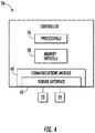
- the controller 26 may include one or more processor(s) 56 and associated memory device(s) 58 configured to perform a variety of computer-implemented functions (e.g., performing the methods, steps, calculations and the like and storing relevant data as disclosed herein). Additionally, the controller 26 may also include a communications module 60 to facilitate communications between the controller 26 and the various components of the wind turbine 10.
- the communications module 60 may include a sensor interface 62 (e.g., one or more analog-to-digital converters) to permit signals transmitted from the vibration sensors 52, 54 to be converted into signals that can be understood and processed by the processors 56.
- the sensors 52, 54 may be communicatively coupled to the communications module 64 using any suitable means.
- the sensors 52, 54 are coupled to the sensor interface 62 via a wired connection.
- the sensors 52, 54 may be coupled to the sensor interface 62 via a wireless connection, such as by using any suitable wireless communications protocol known in the art.
- the vibration sensors 52, 54 may also be coupled to a separate controller that may or may not be located in the control cabinet 38. As such, the sensors 52, 54 may provide related information to the turbine controller 26 and/or the separate controller. It should also be appreciated that, as used herein, the term "monitor" and variations thereof indicates that the various sensors of the wind turbine 10 may be configured to provide a direct measurement of the parameters being monitored and/or an indirect measurement of such parameters. Thus, the sensors described herein may, for example, be used to generate signals relating to the parameter being monitored, which can then be utilized by the controller 26 to determine the condition.
- the term "processor” refers not only to integrated circuits referred to in the art as being included in a computer, but also refers to a controller, a microcontroller, a microcomputer, a programmable logic controller (PLC), an application specific integrated circuit, and other programmable circuits.
- the memory device(s) 58 may generally comprise memory element(s) including, but not limited to, computer readable medium (e.g., random access memory (RAM)), computer readable non-volatile medium (e.g., a flash memory), a floppy disk, a compact disc-read only memory (CD-ROM), a magneto-optical disk (MOD), a digital versatile disc (DVD) and/or other suitable memory elements.
- RAM random access memory
- CD-ROM compact disc-read only memory
- MOD magneto-optical disk
- DVD digital versatile disc
- Such memory device(s) 58 may generally be configured to store suitable computer-readable instructions that, when implemented by the processor(s) 56, configure the controller 26 to perform various functions including, but not limited to, transmitting suitable control signals to implement corrective action(s) in response to a distance signal exceeding a predetermined threshold as described herein, as well as various other suitable computer-implemented functions.
- the turbine controller 26 is further configured to implement an algorithm to detect damage of one or more of the components of the wind turbine 10.
- the controller 26 is configured to implement a method 100 for detecting damage in one or more of the gears 45, 47, 49 of the wind turbine 10.
- the system and methods of the present disclosure are designed to lower the output of healthy components while amplifying the output of damaged components to allow for earliest possible automated threshold detection with minimal false positive events.
- the method 100 includes collecting vibration data 74 relating to the component via the sensors 52, 54. More specifically, as shown in FIG. 6 , the turbine controller 26 is configured to collect vibration data 74 relating to the gears 45, 47, 49 via the sensors 52, 54. Further, as shown, the vibration data 74 may include regions of high energy 76 and regions of low energy 78. Thus, referring back to FIG. 5 , as shown at 104, the method 100 includes identifying at least one low-energy region 78 within the vibration data 74.
- the method 100 includes identifying energy of at least one harmonic or sideband series within at least one of the low-energy regions 76 of the vibration data 74 indicative of a damaged component, including but not limited to gears (such as gears 45, 47, 49), shafts (such as main shaft 30), and/or bearings 39, 70, 72.
- the method 100 includes identifying energy within the vibration data 74 excluding the at least one harmonic or sideband series.
- two low-energy regions 78 are identified, i.e. regions a and b. In additional embodiments, it should be understood that any number of regions may be identified including more than two and less than two regions.
- the top graph illustrates a healthy component
- the bottom graph illustrates a damaged graph.
- a low-energy region 78 illustrating vibration data 74 from a healthy component is illustrated.
- a low-energy region 78 illustrating vibration data 74 from a damaged component i.e. containing a sideband or harmonic series also referred to herein as a damage indication pattern 84
- FIG. 9 illustrates the extracted energy 86 of the damage indication pattern 84 from the low-energy region 78
- FIG. 10 illustrates the low-energy region 78 excluding the extracted energy 86 of the damage indication pattern 84 as indicated by reference character 88.
- the regions of low energy 78 may be identified using kinematic information.
- the controller 26 is configured to utilize the kinematic information to avoid energy content from components operating normally (i.e. not damaged). Such vibration sources are typically inherent in all gearboxes of this design and are removed from the design factor calculation to allow for separation from healthy and damaged components.
- the kinematic information as described herein may include any of the following: the number of gear teeth of one or more gears of the gearbox 34, a rotating speed, the number of planet gears of a planetary state of the gearbox 34, a pitch diameter of the bearing 39, 70, 72, a roller-element or ball diameter of the bearing 39, 70, 72, a contact angle of the bearing 39, 70, 72, or combinations thereof.
- the controller 26 may be configured to store the vibration data 74 in the memory device(s) 58. Once the vibration data 74 is collected and optionally stored, as shown at 110, the controller 26 is configured to determine a damage factor based on the presence of a sideband or harmonic series indicative of a failed component, e.g. the damage indication pattern 84, within the low energy region(s) 78 in comparison to the remaining energy 88 within the region(s) excluding the sideband or harmonic series. For example, as shown in FIG. 6 , to determine the damage factor, the controller 26 may first determine an average amplitude of the energy of at least one harmonic or sideband series within the vibration data 74 indicative of the damaged gear and an average amplitude of the energy excluding the damage indication pattern 84.
- the controller 26 can then determine at least one amplitude ratio by dividing the average amplitude of the region(s) of the damage indication pattern 84 by the average amplitude of the energy excluding the damage indication pattern 84.
- Amplitude Ratio a f avg , dip , a f avg , non ⁇ dip , a
- the controller 26 may subtract one from each of the amplitude ratios to obtain at least one region damage value.
- the controller may amplify the amplitude ratios based on a sensitivity factor S. For example, as shown, the controller 26 may raise the amplitude ratios to an nth power, such as e.g. 2, 3, 4, and so on.
- Region Damage Value a Amplitude Ratio a ⁇ 1 S
- controller 26 may sum a plurality of region damage values and divide the sum by a total number of low-energy regions 78 to calculate the damage ratio.
- Damage Ratio Region Damage Value a + Region Damage Value b 2 2
- the method 100 further includes calculating a damage factor of the component as a function of, at least, the at least one damage ratio.
- the controller 26 may determine a sum of the energy of the damage indication pattern(s) 84 for a plurality of regions from the vibration data 74 using Equation (4) below.
- the controller 26 may determine the sum of the energy of the damage indication pattern 84 by summing an amplitude of each of the plurality of regions of the energy of the damage indication pattern(s) 84, summing the sums of the amplitude from each of the plurality of regions of the energy of the damage indication pattern(s) 84, and amplifying the sum of the sums based on a sensitivity factor S.
- Sum of Damage Indication Pattern Energy ⁇ a 1 a 2 f i , dip + ⁇ b 1 b 2 f i , dip S where f i,dip is the amplitude of the vibration data at the location of the damage indication pattern(s) 84 in region a of the energy of the damage indication pattern 84.
- the method 100 may calculate the damage factor of the component by multiplying the damage ratio by the sum of the energy of the damage indication pattern(s) 84 energy using Equation (5) below.
- Damage Factor Damage Ratio ⁇ Sum of Damage Indication Pattern Energy
- the damage factor may be scaled by any suitable factor to produce an output value within an acceptable range, i.e. to further amplify the difference between healthy and damaged components.
- the method 100 includes comparing the damage factor to a predetermined damage threshold.
- a damage factor exceeding the predetermined damage threshold is indicative of a damaged component.
- the controller 26 may be implement a corrective action or otherwise indicate that the component is damaged. For example, in certain embodiments, the controller 26 may generate an alarm and/or send an alarm signal to an operator.
- the controller 26 may also be configured to continuously calculate and store the damage factor for multiple time periods. As such, the turbine controller 26 is further configured to trend the damage factor over time. Such trending further separates the damage factor values between healthy and damaged components to allow for automated threshold detection.
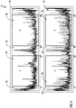
- the first or top row of vibration data 74 represents a healthy component
- the second row of vibration data 74 represents an early damaged component
- the third row of vibration data 74 represents a late damaged component.
- Component damage increases the damage indication pattern energy through the entire spectrum, therefore, comparing damage indication pattern energy to non-damage indication pattern energy outside of normal operation, high energy regions, provides a larger different between damaged and healthy components of the rotary machine.
- the difference between the average amplitude of the damage indication pattern energy 80 and the average energy of the remaining energy 82 is less for healthy components and increases as the component becomes damaged.
Abstract
Description
- The present disclosure relates in general to rotary machines, and more particularly to systems and methods for detecting damage in such rotary machines.
- Wind power is considered one of the cleanest, most environmentally friendly energy sources presently available, and wind turbines have gained increased attention in this regard. A modern wind turbine typically includes a tower, a generator, a gearbox, a nacelle, and one or more rotor blades. The rotor blades capture kinetic energy of wind using known foil principles. The rotor blades transmit the kinetic energy in the form of rotational energy so as to turn a low-speed main shaft coupling the rotor blades to a gearbox, or if a gearbox is not used, directly to the generator. For example, the generator may be coupled to the low-speed main shaft such that rotation of the shaft drives the generator. For instance, the generator may include a high-speed generator shaft rotatably coupled to the main shaft through the gearbox. The generator then converts the mechanical energy from the rotor to electrical energy that may be deployed to a utility grid.
- In addition, modern wind turbines include a plurality of high-speed and low-speed bearings to provide rotation of the various components thereof. For example, the low-speed main shaft typically includes one or more main bearings mounted at a forward and rearward end thereof to allow the low-speed main shaft to rotate about an axis. Further, the gearbox generally includes a gearbox housing containing a plurality of gears (e.g., planet, ring and/or sun gears) connected via one or more planetary carriers and bearings, in addition to parallel gears connected via shafts and bearings, for converting the low speed, high torque input of the rotor shaft to a high speed, low torque output for the generator.
- Detection of damaged components in a wind turbine (or any rotary machine) is essential in minimizing unplanned downtime of the turbine and increasing turbine availability. Current detection algorithms for gearbox gear damage (specifically, the ring gear, planet gear, and low-speed intermediate stage gear) do not consistently trend gear damage energy with enough separation from healthy gears. Lack of separation in the trends from healthy to damaged gears results in missed diagnosis of failing components and increased probability of false positive events for healthy components. Visual detection of failing gear sideband and harmonic energy patterns has proven successful in locating damaged components; however, this approach relies on the consistent manual inspection of the spectrums. Such inspection is inherently time consuming and can result in missed detection of failed components. In addition, although manual inspection methods have been utilized with success, such methods do not provide a scalable option and result in reduced monitoring efficiency.
- For at least the aforementioned reasons, the detection of component damage of rotary machines has proven difficult to automate using traditional detection analytics and/or trending techniques. Accordingly, improved systems and methods for detecting damage in such rotary machines would be desired in the art.
- Various aspects and advantages of the invention will be set forth in part in the following description, or may be clear from the description, or may be learned through practice of the invention.
- In one aspect, the present disclosure is directed to a method for detecting damage in a component of a rotary machine. The method includes collecting, via one or more sensors, vibration data relating to the component. The method also includes identifying at least one low-energy region within the vibration data. The method further includes identifying energy of at least one harmonic or sideband series within the at least one region indicative of a damaged component and identifying energy within the at least one region excluding the at least one harmonic or sideband series. Further, the method includes determining at least one damage ratio based on the energy of at least one harmonic or sideband series within the at least one region indicative of a damaged component and the energy within the at least one region excluding the at least one harmonic or sideband series. Moreover, the method includes calculating a damage factor of the component as a function of, at least, the at least one damage ratio. In addition, the method includes comparing the damage factor to a predetermined damage threshold, wherein a damage factor exceeding the predetermined damage threshold is indicative of a damaged component.
- In one embodiment, the step of determining the damage ratio(s) based on the energy of at least one harmonic or sideband series within the at least one region indicative of the damaged component and the energy within the at least one region excluding the at least one harmonic or sideband series may include determining an average amplitude of the energy of at least one harmonic or sideband series within the at least one region indicative of the damaged component, determining an average amplitude of the identifying energy within the at least one region excluding the at least one harmonic or sideband series, determining at least one amplitude ratio by dividing the average amplitude of the energy of at least one harmonic or sideband series within the at least one region indicative of the damaged component by the average amplitude of the identifying energy within the at least one region excluding the at least one harmonic or sideband series, and subtracting one from the at least one amplitude ratio to obtain at least one region damage value.
- In another embodiment, the method may further include amplifying the amplitude ratio(s) based on a sensitivity factor. For example, in one embodiment, the step of amplifying the amplitude ratio(s) based on the sensitivity factor may include raising the region damage value(s) to an nth power. In further embodiments, the method may include summing a plurality of region damage values, and dividing the sum by a total number of low-energy regions. Further, the method may include identifying the low-energy regions based on kinematic information.
- In additional embodiments, the method may further include determining a sum of the energy of the at least one harmonic or sideband series within the at least one region indicative of the damaged component for a plurality of regions of the at least one region. More specifically, in one embodiment, the step of determining the sum of the energy of the at least one harmonic or sideband series within the at least one region indicative of the damaged component for the plurality of regions of the at least one region may include summing an amplitude of each of the plurality of regions, summing the sums of the amplitude from each of the plurality of regions, and amplifying the sum of the sums based on a sensitivity factor.
- Accordingly, the step of calculating the damage factor of the component may include multiplying the at least one damage ratio by the sum of the energy of the at least one harmonic or sideband series within the at least one region indicative of the damaged component. In further embodiments, the method may include calculating the damage factor for multiple time periods and trending the damage factor over time.
- In several embodiments, the component may include, for example, a gear or a bearing. Further, in certain embodiments, the rotary machine may be a wind turbine.
- In another aspect, the present disclosure is directed to a system for detecting damage in a gear of a rotary machine. The system includes one or more sensors for collecting vibration data relating to the gear and a controller communicatively coupled to the one or more sensors. The controller is configured to perform one or more operations, including but not limited to identifying energy of at least one harmonic or sideband series within the at least one region indicative of a damaged gear and identifying energy within the at least one region excluding the at least one harmonic or sideband series. Further, the method includes determining at least one damage ratio based on the energy of at least one harmonic or sideband series within the at least one region indicative of a damaged gear and the energy within the at least one region excluding the at least one harmonic or sideband series. Moreover, the method includes calculating a damage factor of the gear as a function of, at least, the at least one damage ratio. In addition, the method includes comparing the damage factor to a predetermined damage threshold, wherein a damage factor exceeding the predetermined damage threshold is indicative of a damaged gear. It should also be understood that the system may further include any of the additional features and/or steps described herein.
- In yet another aspect, the present disclosure is directed to a method for detecting damage in a gear of a wind turbine. The method includes collecting, via one or more sensors, vibration data relating to the gear. The method also includes identifying at least one low-energy region within the vibration data. Further, the method includes identifying energy of at least one harmonic or sideband series within the at least one region indicative of a damaged gear. Moreover, the method includes identifying energy within the at least one region excluding the at least one harmonic or sideband series. The method also includes comparing the energy of at least one harmonic or sideband series within the at least one region indicative of the damaged gear and the energy within the at least one region excluding the at least one harmonic or sideband series. In addition, the method includes calculating a damage factor of the gear based, at least in part, on the comparison. As such, the method includes determining whether damage is present in the gear based on the damage factor. It should also be understood that the method may further include any of the additional features and/or steps described herein.
- Various features, aspects and advantages of the present invention will become better understood with reference to the following description and appended claims. The accompanying drawings, which are incorporated in and constitute a part of this specification, illustrate embodiments of the invention and, together with the description, serve to explain the principles of the invention.
- In the drawings:
-
FIG. 1 illustrates a perspective view of a wind turbine according to one embodiment of the present disclosure; -
FIG. 2 illustrates a perspective, internal view of a nacelle of a wind turbine according to one embodiment of the present disclosure; -
FIG. 3 illustrates a cross-sectional view of one embodiment of a drivetrain system of a wind turbine according to the present disclosure; -
FIG. 4 illustrates a block diagram of one embodiment of suitable components that may be included in a wind turbine controller according to the present disclosure; -
FIG. 5 illustrates a flow diagram of one embodiment of a method for detecting damage in a component of a rotary machine according to the present disclosure; -
FIG. 6 illustrates a graph of one embodiment of vibration data according to the present disclosure; -
FIG. 7 illustrates a graph of a low-energy region of vibration data of a component without damage according to the present disclosure; -
FIG. 8 illustrates a graph of a low-energy region of vibration data of a component with damage according to the present disclosure; -
FIG. 9 illustrates a graph of a low-energy region of vibration data of a component, particularly illustrating extracted energy of a damage indication pattern according to the present disclosure; -
FIG. 10 illustrates a graph of a low-energy region of vibration data of a component, particularly illustrating remaining energy according to the present disclosure; and -
FIG. 11 illustrates a plurality of graphs depicting vibration data for a healthy component of a rotary machine, an early-stage damaged component, and a late-stage damaged component according to the present disclosure. - Reference now will be made in detail to embodiments of the invention, one or more examples of which are illustrated in the drawings. Each example is provided by way of explanation of the invention, not limitation of the invention. In fact, it will be apparent to those skilled in the art that various modifications and variations can be made in the present invention without departing from the scope or spirit of the invention. For instance, features illustrated or described as part of one embodiment can be used with another embodiment to yield a still further embodiment. Thus, it is intended that the present invention covers such modifications and variations as come within the scope of the appended claims and their equivalents.
- Generally, the present disclosure is directed to systems and methods for detecting damaged components in rotary machines, such as wind turbine, that utilize vibration spectrum data to trend the energy of patterns associated with component damage. More specifically, algorithms of the present disclosure generate a scalar value, or damage factor, which can be trended over time to indicate damage propagation in the components of the rotary machines. For example, for wind turbine gearboxes, the present disclosure detects damage of the planetary stage gears (e.g. the ring gear, planet gears, and sun gear), as well as higher-speed parallel gear stages by lowering the output of healthy components while amplifying the output of damaged components to allow for earliest possible automated threshold detection with minimal false positive events. Such separation between damaged and healthy components allows for lower thresholds to be set to alert technicians of damaged components. Thus, the present disclosure increases machine availability by reducing unplanned downtime, prolonging component life, reducing potential secondary damage, and increasing monitoring efficiency for accurate component damage detection.
- Referring now to the drawings,
FIG. 1 illustrates a perspective view of one embodiment of awind turbine 10 according to the present disclosure. Though the present disclosure is described with reference to wind turbines, it should be understood that the systems and methods of the present disclosure may be applicable to any rotary machines (e.g., gas turbines, steam turbines, or any other turbine system for power generation). As shown, thewind turbine 10 includes atower 12 extending from asupport surface 14, anacelle 16 mounted on thetower 12, and arotor 18 coupled to thenacelle 16. Therotor 18 includes arotatable hub 20 and at least onerotor blade 22 coupled to and extending outwardly from thehub 20. For example, in the illustrated embodiment, therotor 18 includes threerotor blades 22. However, in an alternative embodiment, therotor 18 may include more or less than threerotor blades 22. Eachrotor blade 22 may be spaced about thehub 20 to facilitate rotating therotor 18 to enable kinetic energy to be transferred from the wind into usable mechanical energy, and subsequently, electrical energy. For instance, thehub 20 may be rotatably coupled to drivetrain system 28 (FIG. 2 ) positioned within thenacelle 16 to permit electrical energy to be produced. - Referring now to
FIG. 2 , a simplified, internal view of one embodiment of thenacelle 16 of thewind turbine 10 housing thedrivetrain system 28 therein is illustrated. As shown, thedrivetrain system 28 includes, at least, agenerator 24 disposed within thenacelle 16. In general, thegenerator 24 may be coupled to therotor 18 of thewind turbine 10 for generating electrical power from the rotational energy generated by therotor 18. For example, therotor 18 may include amain shaft 30 coupled to thehub 20 for rotation therewith. Thegenerator 24 may then be coupled to themain shaft 30 such that rotation of themain shaft 30 drives thegenerator 24. For instance, in the illustrated embodiment, thegenerator 24 includes agenerator shaft 29 rotatably coupled to themain shaft 30 through agearbox 34. However, in other embodiments, it should be appreciated that thegenerator shaft 29 may be rotatably coupled directly to themain shaft 30. Alternatively, thegenerator 24 may be directly rotatably coupled to themain shaft 30. It should be appreciated that themain shaft 30 may generally be supported within thenacelle 16 by a support frame orbedplate 36 positioned atop thewind turbine tower 12. - As shown in
FIGS. 1 and2 , thewind turbine 10 may also include a turbine control system or aturbine controller 26 within thenacelle 16. For example, as shown inFIG. 2 , theturbine controller 26 is disposed within acontrol cabinet 38 mounted to a portion of thenacelle 16. However, it should be appreciated that theturbine controller 26 may be disposed at any location on or in thewind turbine 10, at any location on thesupport surface 14 or generally at any other location. Theturbine controller 26 may generally be configured to control the various operating modes (e.g., start-up or shut-down sequences) and/or components of thewind turbine 10. - Each
rotor blade 22 may also include apitch adjustment mechanism 40 configured to rotate eachrotor blade 22 about itspitch axis 42 viapitch bearing 44. Similarly, thewind turbine 10 may include one or moreyaw drive mechanisms 46 communicatively coupled to thecontroller 26, with each yaw drive mechanism(s) 46 being configured to change the angle of thenacelle 16 relative to the wind (e.g., by engaging a yaw bearing 48 of thewind turbine 10 to rotate thenacelle 16 about yaw axis 50). - In addition, as shown in
FIG. 2 , thewind turbine 10 may further include one ormore sensors sensors gearbox 34 and/or any other components of thedrivetrain system 28 so as to detect damage of one or more of the components described herein. As such, thesensors wind turbine 10 may include any suitable number of sensors for detecting such vibrations. - Referring now to
FIG. 3 , a detailed, cross-sectional view of thedrivetrain system 28 of thewind turbine 10 is illustrated to further depict the various components thereof. As mentioned, thedrivetrain system 28 includes, at least, thegenerator 24 and thegearbox 34. Further, as shown, thegenerator 24 includes agenerator rotor 25 and agenerator stator 27. As is generally known in the art, thegenerator rotor 25 is a generally movable component of thegenerator 24, while thestator 27 is a generally stationary component of thegenerator 24. Further, in certain embodiments, thegenerator 24 may be a doubly-fed induction generator (DFIG). However, it should be understood that thegenerator 24 according to the present disclosure is not limited to DFIG generators, and may include any generator suitable for powering thewind turbine 10 of the present disclosure. In general, therotor blades 16 rotate thegenerator rotor 25 of thegenerator 24. As such, thegenerator rotor 25 may be operably connected to thehub 18. Accordingly, operation of therotor blades 16 rotates therotor hub 18, which rotates thegenerator rotor 25 and thus operates thegenerator 24. - Further, as shown, the low-speed
main shaft 30 is configured to provide an input rotational speed to thegearbox 34. For example, thehub 18 may be mounted to themain shaft 30. As shown, themain shaft 30 may include amain flange 41 configured to engage a mating flange (not shown) on thehub 18 to mount thehub 18 to themain shaft 30. Thus, during operation of thewind turbine 10, the rotational speed of therotor blades 16 may be directly transmitted through thehub 18 to themain shaft 30 as an input rotational speed. - The
main shaft 30 may extend through and be supported by at least onesupport housing 35 or a plurality ofsupport housings 35. For example, aforward housing 37 and, in some embodiments, an aft housing (not shown), may be provided to support themain shaft 30. In addition, thehousings 35 may include one ormore bearings 39 configured to interact with themain shaft 30. For example, as shown, theforward housing 37 may include a locating bearing 39 (also referred to herein as a main shaft bearing 39) configured therein, while the aft housing may include a floating bearing (not shown) configured therein. It should be understood that the present disclosure is not limited to locating bearings and floating bearings positioned in housings as described above and the figures are provided for illustrative purposes only. Further, as shown, the main shaft bearing(s) 39 may include aninner race 31, anouter race 32, and aplurality roller elements 33 configured therebetween. - Still referring to
FIG. 3 , thegearbox 34 as described herein may be aplanetary gearbox 34. As such, thegearbox 34 may be configured to convert the input rotational speed from themain shaft 30 to an output rotational speed. In one embodiment, the output rotational speed may be faster than the input rotational speed. Alternatively, however, the output rotational speed may be slower than the input rotational speed. In one embodiment, thegearbox 34 maybe a single stage gearbox. Thus, the input rotational speed may be converted to the output rotational speed through a single stage of various mating gears, as discussed below. Alternatively, however, thegearbox 34 may be a multiple stage gearbox, and the input rotational speed may be converted to the output rotational speed through multiple stages of various mating gears. - More specifically, the illustrated embodiment of the
planetary gearbox 34 includes astationary ring gear 45 and a plurality of rotatable gears. As such, thestationary ring gear 45 supports the various rotatable gears configured therein. In addition, thestationary ring gear 45 includes various axes for the rotatable gears to rotate about. In certain embodiments, theplanetary gearbox 34 may also include astationary ring gear 45, one or more rotatableplanetary gears 47, and arotatable sun gear 49. For example, in one embodiment, theplanetary gearbox 34 may include fourplanetary gears 47. However, it should be understood that more or less than fourplanetary gears 47 are within the scope and spirit of the present disclosure. In addition, each of the rotatable gears in theplanetary gearbox 34 includes a plurality of gear teeth (not shown). As such, the teeth may mesh together such that thevarious gears - In several embodiments, the
carrier 43 may drive theplanetary gearbox 34. Thus, thecarrier 43 and themain shaft 30 may be coupled such that the input rotational speed of themain shaft 30 is provided to thecarrier 43. For example, a gearbox disk may connect thecarrier 43 andmain shaft 30, or thecarrier 43 andmain shaft 30 may be otherwise suitably connected. Alternatively, however, thering gear 45 or thesun gear 49 may drive theplanetary gearbox 34. - Referring still to
FIG. 3 and as mentioned, thedrivetrain system 28 of the present disclosure may further include an output orgenerator shaft 29. More specifically, as shown, thegenerator shaft 29 may be coupled with thegearbox 34, and configured to rotate at the output rotational speed. In particular embodiments, for example, thegenerator shaft 29 may be thesun gear 49. Thus, thesun gear 49 may engage theplanetary gears 47 and may further extend from theplanetary gearbox 34 towards thegenerator 24. In other embodiments, thegenerator shaft 29 may be coupled to thesun gear 49 or other output gear of theplanetary gearbox 34 or other suitable gearbox such that thegenerator shaft 29 may rotate at the output rotational speed. - In addition,
various bearings drivetrain system 28 to facilitate relatively efficient rotation of such rotatable components. For example, as shown, a plurality ofcarrier bearings 70 may surround theplanetary carrier 43 and a plurality ofplanet bearings 72 may surround theplanetary gears 47 and/or additional bearings which support the sun gear or sun gear shaft (not shown).Such bearings bearings - Referring now to
FIG. 4 , there is illustrated a block diagram of one embodiment of suitable components that may be included within the controller 26 (or a separate controller) according to the present disclosure. As shown, thecontroller 26 may include one or more processor(s) 56 and associated memory device(s) 58 configured to perform a variety of computer-implemented functions (e.g., performing the methods, steps, calculations and the like and storing relevant data as disclosed herein). Additionally, thecontroller 26 may also include acommunications module 60 to facilitate communications between thecontroller 26 and the various components of thewind turbine 10. Further, thecommunications module 60 may include a sensor interface 62 (e.g., one or more analog-to-digital converters) to permit signals transmitted from thevibration sensors processors 56. It should be appreciated that thesensors FIG. 4 , thesensors sensor interface 62 via a wired connection. However, in other embodiments, thesensors sensor interface 62 via a wireless connection, such as by using any suitable wireless communications protocol known in the art. - In additional embodiments, the
vibration sensors control cabinet 38. As such, thesensors turbine controller 26 and/or the separate controller. It should also be appreciated that, as used herein, the term "monitor" and variations thereof indicates that the various sensors of thewind turbine 10 may be configured to provide a direct measurement of the parameters being monitored and/or an indirect measurement of such parameters. Thus, the sensors described herein may, for example, be used to generate signals relating to the parameter being monitored, which can then be utilized by thecontroller 26 to determine the condition. - As used herein, the term "processor" refers not only to integrated circuits referred to in the art as being included in a computer, but also refers to a controller, a microcontroller, a microcomputer, a programmable logic controller (PLC), an application specific integrated circuit, and other programmable circuits. Additionally, the memory device(s) 58 may generally comprise memory element(s) including, but not limited to, computer readable medium (e.g., random access memory (RAM)), computer readable non-volatile medium (e.g., a flash memory), a floppy disk, a compact disc-read only memory (CD-ROM), a magneto-optical disk (MOD), a digital versatile disc (DVD) and/or other suitable memory elements. Such memory device(s) 58 may generally be configured to store suitable computer-readable instructions that, when implemented by the processor(s) 56, configure the
controller 26 to perform various functions including, but not limited to, transmitting suitable control signals to implement corrective action(s) in response to a distance signal exceeding a predetermined threshold as described herein, as well as various other suitable computer-implemented functions. - Referring now to
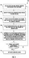
FIG. 5 , theturbine controller 26 is further configured to implement an algorithm to detect damage of one or more of the components of thewind turbine 10. For example, in one embodiment, thecontroller 26 is configured to implement amethod 100 for detecting damage in one or more of thegears wind turbine 10. Thus, as shown, the system and methods of the present disclosure are designed to lower the output of healthy components while amplifying the output of damaged components to allow for earliest possible automated threshold detection with minimal false positive events. - As shown at 102, the
method 100 includes collectingvibration data 74 relating to the component via thesensors FIG. 6 , theturbine controller 26 is configured to collectvibration data 74 relating to thegears sensors vibration data 74 may include regions ofhigh energy 76 and regions oflow energy 78. Thus, referring back toFIG. 5 , as shown at 104, themethod 100 includes identifying at least one low-energy region 78 within thevibration data 74. As shown at 106, themethod 100 includes identifying energy of at least one harmonic or sideband series within at least one of the low-energy regions 76 of thevibration data 74 indicative of a damaged component, including but not limited to gears (such asgears bearings method 100 includes identifying energy within thevibration data 74 excluding the at least one harmonic or sideband series. For example, as shown inFIG. 6 , two low-energy regions 78 are identified, i.e. regions a and b. In additional embodiments, it should be understood that any number of regions may be identified including more than two and less than two regions. Further, as shown, the top graph illustrates a healthy component, whereas the bottom graph illustrates a damaged graph. More specifically, as shown inFIG. 7 , a low-energy region 78 illustratingvibration data 74 from a healthy component is illustrated. In contrast, as shown inFIG. 8 , a low-energy region 78 illustratingvibration data 74 from a damaged component (i.e. containing a sideband or harmonic series also referred to herein as a damage indication pattern 84) is illustrated. More specifically,FIG. 9 illustrates the extractedenergy 86 of thedamage indication pattern 84 from the low-energy region 78 andFIG. 10 illustrates the low-energy region 78 excluding the extractedenergy 86 of thedamage indication pattern 84 as indicated byreference character 88. - In addition, the regions of
low energy 78 may be identified using kinematic information. Thus, to extract the desired energy of damaged components, thecontroller 26 is configured to utilize the kinematic information to avoid energy content from components operating normally (i.e. not damaged). Such vibration sources are typically inherent in all gearboxes of this design and are removed from the design factor calculation to allow for separation from healthy and damaged components. The kinematic information as described herein may include any of the following: the number of gear teeth of one or more gears of thegearbox 34, a rotating speed, the number of planet gears of a planetary state of thegearbox 34, a pitch diameter of thebearing bearing bearing - In addition, the
controller 26 may be configured to store thevibration data 74 in the memory device(s) 58. Once thevibration data 74 is collected and optionally stored, as shown at 110, thecontroller 26 is configured to determine a damage factor based on the presence of a sideband or harmonic series indicative of a failed component, e.g. thedamage indication pattern 84, within the low energy region(s) 78 in comparison to the remainingenergy 88 within the region(s) excluding the sideband or harmonic series. For example, as shown inFIG. 6 , to determine the damage factor, thecontroller 26 may first determine an average amplitude of the energy of at least one harmonic or sideband series within thevibration data 74 indicative of the damaged gear and an average amplitude of the energy excluding thedamage indication pattern 84. - Thus, as shown in Equation (1), the
controller 26 can then determine at least one amplitude ratio by dividing the average amplitude of the region(s) of thedamage indication pattern 84 by the average amplitude of the energy excluding thedamage indication pattern 84.
- where favg,dip,a is the average amplitude of region a of the energy in the
damage indication pattern 84, and - favg,non-dip,a is the average amplitude of region a of the energy excluding the
damage indication pattern 84. - Further, as shown in Equation (2) below, the
controller 26 may subtract one from each of the amplitude ratios to obtain at least one region damage value. In addition, as shown in Equation (s), the controller may amplify the amplitude ratios based on a sensitivity factor S. For example, as shown, thecontroller 26 may raise the amplitude ratios to an nth power, such as e.g. 2, 3, 4, and so on.
- In addition, the
controller 26 may sum a plurality of region damage values and divide the sum by a total number of low-energy regions 78 to calculate the damage ratio. In the illustrated embodiment ofFIG. 6 , for example, there are twolow energy regions 78 labeled a and b, respectively.
- Referring back to
FIG. 5 , as shown at 112, themethod 100 further includes calculating a damage factor of the component as a function of, at least, the at least one damage ratio. For example, in one embodiment, thecontroller 26 may determine a sum of the energy of the damage indication pattern(s) 84 for a plurality of regions from thevibration data 74 using Equation (4) below. More specifically, as shown, thecontroller 26 may determine the sum of the energy of thedamage indication pattern 84 by summing an amplitude of each of the plurality of regions of the energy of the damage indication pattern(s) 84, summing the sums of the amplitude from each of the plurality of regions of the energy of the damage indication pattern(s) 84, and amplifying the sum of the sums based on a sensitivity factor S.
damage indication pattern 84. - Accordingly, the
method 100 may calculate the damage factor of the component by multiplying the damage ratio by the sum of the energy of the damage indication pattern(s) 84 energy using Equation (5) below.
- In addition, the damage factor may be scaled by any suitable factor to produce an output value within an acceptable range, i.e. to further amplify the difference between healthy and damaged components.
- Referring still to
FIG. 5 , as shown at 112, once the damage factor is calculated, themethod 100 includes comparing the damage factor to a predetermined damage threshold. A damage factor exceeding the predetermined damage threshold is indicative of a damaged component. Thus, as shown at 114, if the damage factor exceeds the predetermined threshold, then thecontroller 26 may be implement a corrective action or otherwise indicate that the component is damaged. For example, in certain embodiments, thecontroller 26 may generate an alarm and/or send an alarm signal to an operator. - In further embodiments, the
controller 26 may also be configured to continuously calculate and store the damage factor for multiple time periods. As such, theturbine controller 26 is further configured to trend the damage factor over time. Such trending further separates the damage factor values between healthy and damaged components to allow for automated threshold detection. - Advantages of the present disclosure can be further understood with respect to
FIG. 11 . More specifically, as shown, the first or top row ofvibration data 74 represents a healthy component, the second row ofvibration data 74 represents an early damaged component, and the third row ofvibration data 74 represents a late damaged component. Component damage increases the damage indication pattern energy through the entire spectrum, therefore, comparing damage indication pattern energy to non-damage indication pattern energy outside of normal operation, high energy regions, provides a larger different between damaged and healthy components of the rotary machine. Thus, as shown, the difference between the average amplitude of the damageindication pattern energy 80 and the average energy of the remainingenergy 82 is less for healthy components and increases as the component becomes damaged. - This written description uses examples to disclose the invention, including the preferred mode, and also to enable any person skilled in the art to practice the invention, including making and using any devices or systems and performing any incorporated methods. The patentable scope of the invention is defined by the claims, and may include other examples that occur to those skilled in the art. Such other examples are intended to be within the scope of the claims if they include structural elements that do not differ from the literal language of the claims, or if they include equivalent structural elements with insubstantial differences from the literal languages of the claims.
- Various aspects and embodiments of the present invention are defined by the following numbered clauses:
- 1. A method for detecting damage in a component of a rotary machine, the method comprising:
- collecting, via one or more sensors, vibration data relating to the component;
- identifying at least one low-energy region within the vibration data;
- identifying energy of at least one harmonic or sideband series within the at least one region indicative of a damaged component;
- identifying energy within the at least one region excluding the at least one harmonic or sideband series;
- determining at least one damage ratio based on the energy of at least one harmonic or sideband series within the at least one region indicative of the damaged component and the energy within the at least one region excluding the at least one harmonic or sideband series;
- calculating a damage factor of the component as a function of, at least, the at least one damage ratio; and,
- comparing the damage factor to a predetermined damage threshold, wherein a damage factor exceeding the predetermined damage threshold is indicative of the damaged component.
- 2. The method of clause 1, wherein determining the at least one damage ratio based on the energy of at least one harmonic or sideband series within the at least one region indicative of the damaged component and the energy within the at least one region excluding the at least one harmonic or sideband series further comprises:
- determining an average amplitude of the energy of at least one harmonic or sideband series within the at least one region indicative of the damaged component;
- determining an average amplitude of the identifying energy within the at least one region excluding the at least one harmonic or sideband series;
- determining at least one amplitude ratio by dividing the average amplitude of the energy of at least one harmonic or sideband series within the at least one region indicative of the damaged component by the average amplitude of the identifying energy within the at least one region excluding the at least one harmonic or sideband series; and,
- subtracting one from the at least one amplitude ratio to obtain at least one region damage value.
- 3. The method of any preceding clause, further comprising amplifying the at least one amplitude ratio based on a sensitivity factor.
- 4. The method of any preceding clause, wherein amplifying the at least one amplitude ratio based on the sensitivity factor further comprises:
raising the at least one amplitude ratio to an nth power. - 5. The method of any preceding clause, further comprising:
- summing a plurality of region damage values; and,
- dividing the sum by a total number of low-energy regions.
- 6. The method of any preceding clause, further comprising identifying the low-energy regions based on kinematic information.
- 7. The method of any preceding clause, further comprising determining a sum of the energy of the at least one harmonic or sideband series within the at least one region indicative of the damaged component for a plurality of regions of the vibration data.
- 8. The method of any preceding clause, wherein determining the sum of the energy of the at least one harmonic or sideband series within the at least one region indicative of the damaged component for the plurality of regions of the at least one region further comprises:
- summing an amplitude of each of the plurality of regions;
- summing the sums of the amplitude from each of the plurality of regions; and,
- amplifying the sum of the sums based on a sensitivity factor.
- 9. The method of any preceding clause, wherein calculating the damage factor of the component further comprises:
- multiplying the at least one damage ratio by the sum of the energy of the at least one harmonic or sideband series within the at least one region indicative of the damaged component for the plurality of regions of the at least one region.
- 10. The method of any preceding clause, further comprising calculating the damage factor for multiple time periods and trending the damage factor over time.
- 11. The method of any preceding clause, wherein the component comprises at least one of a gear or a bearing.
- 12. The method of any preceding clause, wherein the rotary machine comprises a wind turbine.
- 13. A system for detecting damage in a gear of a rotary machine, the system comprising:
- one or more sensors for collecting vibration data relating to the gear;
- a controller communicatively coupled to the one or more sensors, the controller configured to perform one or more operations, the one or more operations comprising:
- identifying at least one low-energy region within the at least one region;
- identifying energy of at least one harmonic or sideband series within the at least one region indicative of a damaged gear;
- identifying energy within the at least one region excluding the at least one harmonic or sideband series;
- determining at least one damage ratio based on the energy of at least one harmonic or sideband series within the at least one region indicative of the damaged gear and the energy within the at least one region excluding the at least one harmonic or sideband series;
- calculating a damage factor of the gear as a function of, at least, the at least one damage ratio; and,
- comparing the damage factor to a predetermined damage threshold, wherein a damage factor exceeding the predetermined damage threshold is indicative of the damaged gear.
- 14. The system of any preceding clause, wherein determining the at least one damage ratio based on the energy of at least one harmonic or sideband series within the at least one region indicative of the damaged gear and the energy within the at least one region excluding the at least one harmonic or sideband series further comprises:
- determining an average amplitude of the energy of at least one harmonic or sideband series within the at least one region indicative of the damaged gear;
- determining an average amplitude of the identifying energy within the at least one region excluding the at least one harmonic or sideband series;
- determining at least one amplitude ratio by dividing the average amplitude of the energy of at least one harmonic or sideband series within the at least one region indicative of the damaged gear by the average amplitude of the identifying energy within the at least one region excluding the at least one harmonic or sideband series;
- subtracting one from the at least one amplitude ratio to obtain at least one region damage value; and,
- amplifying the at least one amplitude ratio based on a sensitivity factor.
- 15. The system of any preceding clause, wherein the one or more operations further comprise:
- summing a plurality of region damage values; and,
- dividing the sum by a total number of low-energy regions.
- 16. The method of any preceding clause, wherein the one or more operations further comprise identifying the low-energy regions based on kinematic information.
- 17. The system of any preceding clause, wherein the one or more operations further comprise determining a sum of the energy of the at least one harmonic or sideband series within the at least one region indicative of the damaged component for a plurality of regions of the at least one region.
- 18. The system of any preceding clause, wherein determining the sum of the energy of the at least one harmonic or sideband series within the at least one region indicative of the damaged component for the plurality of regions of the at least one region further comprises:
- summing an amplitude of each of the plurality of regions;
- summing the sums of the amplitude from each of the plurality of regions; and,
- amplifying the sum of the sums based on a sensitivity factor.
- 19. The method of any preceding clause, wherein calculating the damage factor of the component further comprises:
- multiplying the at least one damage ratio by the sum of the energy of the at least one harmonic or sideband series within the at least one region indicative of the damaged component for the plurality of regions of the at least one region.
- 20. A method for detecting damage in a gear of a wind turbine, the method comprising:
- collecting, via one or more sensors, vibration data relating to the gear;
- identifying at least one low-energy region within the vibration data;
- identifying energy of at least one harmonic or sideband series within the at least one region indicative of a damaged gear;
- identifying energy within the at least one region excluding the at least one harmonic or sideband series;
- comparing the energy of at least one harmonic or sideband series within the at least one region indicative of the damaged gear and the energy within the at least one region excluding the at least one harmonic or sideband series;
- calculating a damage factor of the gear based, at least in part, on the comparison; and,
- determining whether damage is present in the gear based on the damage factor.
Claims (15)
- A method (100) for detecting damage in a component of a rotary machine, the method (100) comprising:collecting (102), via one or more sensors (52, 54), vibration data (74) relating to the component;identifying (104) at least one low-energy region (78) within the vibration data (74);identifying (106) energy (86) of at least one harmonic or sideband series within the at least one low-energy region (78) indicative of a damaged component;identifying (108) energy (88) within the at least one low-energy region (78) excluding the energy (86) of the at least one harmonic or sideband series;determining (110) at least one damage ratio based on the energy (86) of at least one harmonic or sideband series within the at least one low-energy region (78) indicative of the damaged component and the energy (88) within the at least one low-energy region (78) excluding the at least one harmonic or sideband series;calculating a damage factor of the component as a function of, at least, the at least one damage ratio; andcomparing (112) the damage factor to a predetermined damage threshold, wherein a damage factor exceeding the predetermined damage threshold is indicative of the damaged component.
- The method (100) of claim 1, determining at least one damage ratio based on the energy (86) of at least one harmonic or sideband series within the at least one low-energy region (78) indicative of the damaged component and the energy (88) within the at least one low-energy region (78) excluding the at least one harmonic or sideband series further comprises:determining an average amplitude (80) of the energy (86) of at least one harmonic or sideband series within the at least one low-energy region (78) indicative of the damaged component;determining an average amplitude (82) of the energy (88) within the at least one low-energy region (78) excluding the at least one harmonic or sideband series;determining at least one amplitude ratio by dividing the average amplitude (80) of the energy (86) of at least one harmonic or sideband series within the at least one low-energy region (78) indicative of the damaged component by the average amplitude (82) of the identifying energy (88) within the at least one low-energy region (78) excluding the at least one harmonic or sideband series; and,subtracting one from the at least one amplitude ratio to obtain at least one region damage value.
- The method (100) of claim 2, further comprising amplifying the at least one amplitude ratio based on a sensitivity factor.
- The method (100) of claim 3, wherein amplifying the at least one amplitude ratio based on the sensitivity factor further comprises raising the at least one amplitude ratio to an nth power.
- The method (100) of any of claims 2 to 4, further comprising:summing a plurality of region damage values; anddividing the sum by a total number of low-energy regions (78).
- The method (100) of claim 5, further comprising identifying the low-energy regions (78) based on kinematic information.
- The method (100) of any of the preceding claims, further comprising determining a sum of the energy (86) of the at least one harmonic or sideband series within the at least one low-energy region (78) indicative of the damaged component for a plurality of regions (78) of the vibration data (74).
- The method (100) of claim 7, wherein determining the sum of the energy (86) of the at least one harmonic or sideband series within the at least one low-energy region (78) indicative of the damaged component for the plurality of regions (78) of the at least one low-energy region (78) further comprises:summing an amplitude of each of the plurality of regions (78);summing the sums of the amplitude from each of the plurality of regions (78); andamplifying the sum of the sums based on a sensitivity factor.
- The method (100) of claim 7 or claim 8, wherein calculating the damage factor of the component further comprises:multiplying the at least one damage ratio by the sum of the energy (86) of the at least one harmonic or sideband series within the at least one low-energy region (78) indicative of the damaged component for the plurality of regions (78) of the at least one low-energy region (78).
- The method (100) of any of the preceding claims, further comprising calculating the damage factor for multiple time periods and trending the damage factor over time.
- The method (100) of any of the preceding claims, wherein the component comprises at least one of a gear (45, 47, 49) or a bearing (39, 70, 72).
- The method (100) of any of the preceding claims, wherein the rotary machine comprises a wind turbine (10).
- A system for detecting damage in a gear (45, 47, 49) of a rotary machine, the system comprising:one or more sensors (52, 54) for collecting vibration data (74) relating to the gear;a controller (26) communicatively coupled to the one or more sensors (52, 54), the controller (26) configured to perform one or more operations, the one or more operations comprising:identifying at least one low-energy region (78) within the at least one low-energy region (78);identifying energy (86) of at least one harmonic or sideband series within the at least one low-energy region (78) indicative of a damaged gear (45, 47, 49);identifying energy (88) within the at least one low-energy region (78) excluding the at least one harmonic or sideband series;determining at least one damage ratio based on the energy (86) of at least one harmonic or sideband series within the at least one low-energy region (78) indicative of the damaged gear and the energy (88) within the at least one low-energy region (78) excluding the at least one harmonic or sideband series;calculating a damage factor of the gear (45, 47, 49) as a function of, at least, the at least one damage ratio; andcomparing the damage factor to a predetermined damage threshold, wherein a damage factor exceeding the predetermined damage threshold is indicative of the damaged gear (45, 47, 49).
- The system of claim 13, wherein determining the at least one damage ratio based on the energy (86) of at least one harmonic or sideband series within the at least one low-energy region (78) indicative of the damaged gear (45, 47, 49) and the energy (88) within the at least one low-energy region (78) excluding the at least one harmonic or sideband series further comprises:determining an average amplitude (80) of the energy (86) of at least one harmonic or sideband series within the at least one low-energy region (78) indicative of the damaged gear;determining an average amplitude (82) of the identifying energy (88) within the at least one low-energy region (78) excluding the at least one harmonic or sideband series;determining at least one amplitude ratio by dividing the average amplitude (80) of the energy (86) of at least one harmonic or sideband series within the at least one low-energy region (78) indicative of the damaged gear (45, 47, 49) by the average amplitude (82) of the energy (88) within the at least one low-energy region (78) excluding the at least one harmonic or sideband series;subtracting one from the at least one amplitude ratio to obtain at least one region damage value; andamplifying the at least one amplitude ratio based on a sensitivity factor.
- The system of claim 14, wherein the one or more operations further comprise:summing a plurality of region damage values; anddividing the sum by a total number of low-energy regions (78).
Applications Claiming Priority (1)
| Application Number | Priority Date | Filing Date | Title |
|---|---|---|---|
| US15/678,238 US10488372B2 (en) | 2017-08-16 | 2017-08-16 | Systems and methods for detecting damage in rotary machines |
Publications (1)
| Publication Number | Publication Date |
|---|---|
| EP3444576A1 true EP3444576A1 (en) | 2019-02-20 |
Family
ID=63209241
Family Applications (1)
| Application Number | Title | Priority Date | Filing Date |
|---|---|---|---|
| EP18188411.5A Pending EP3444576A1 (en) | 2017-08-16 | 2018-08-10 | Systems and methods for detecting damage in rotary machines |
Country Status (3)
| Country | Link |
|---|---|
| US (1) | US10488372B2 (en) |
| EP (1) | EP3444576A1 (en) |
| CN (1) | CN109404226B (en) |
Cited By (1)
| Publication number | Priority date | Publication date | Assignee | Title |
|---|---|---|---|---|
| EP3904672A1 (en) * | 2020-04-30 | 2021-11-03 | General Electric Company | System and method for controlling a wind turbine in response to a blade liberation event |
Families Citing this family (2)
| Publication number | Priority date | Publication date | Assignee | Title |
|---|---|---|---|---|
| US10655607B2 (en) * | 2017-06-02 | 2020-05-19 | General Electric Company | Systems and methods for detecting damage in wind turbine bearings |
| CN114897034B (en) * | 2022-07-14 | 2022-10-28 | 深圳市信润富联数字科技有限公司 | Stamping die supervision method, device, equipment and storage medium |
Citations (6)
| Publication number | Priority date | Publication date | Assignee | Title |
|---|---|---|---|---|
| US20020169569A1 (en) * | 2001-03-13 | 2002-11-14 | Niel Miller | System and method for analyzing vibration signals |
| US20120065901A1 (en) * | 2009-11-16 | 2012-03-15 | Nrg Systems, Inc. | Data acquisition system for condition-based maintenance |
| US20140257714A1 (en) * | 2011-10-13 | 2014-09-11 | Moventas Gears Oy | Method and a system for the purpose of condition monitoring of gearboxes |
| US20150355044A1 (en) * | 2014-06-06 | 2015-12-10 | General Electric Company | System and Method for Protecting Rotary Machines |
| US20170145852A1 (en) * | 2015-11-23 | 2017-05-25 | United Technologies Corporation | Systems and methods for monitoring gearbox health by vibration |
| WO2017168226A1 (en) * | 2016-03-30 | 2017-10-05 | 3D Signals Ltd. | Acoustic monitoring of machinery |
Family Cites Families (23)
| Publication number | Priority date | Publication date | Assignee | Title |
|---|---|---|---|---|
| US6393902B1 (en) * | 1998-06-29 | 2002-05-28 | Veri-Tek Inc. | Noise testing system with temperature responsive sensitivity |
| US6078874A (en) * | 1998-08-04 | 2000-06-20 | Csi Technology, Inc. | Apparatus and method for machine data collection |
| US20050171736A1 (en) * | 2004-02-02 | 2005-08-04 | United Technologies Corporation | Health monitoring and diagnostic/prognostic system for an ORC plant |
| US7912659B2 (en) * | 2004-06-28 | 2011-03-22 | General Electric Company | System and method for monitoring the condition of a drive train |
| WO2006030786A1 (en) * | 2004-09-13 | 2006-03-23 | Nsk Ltd. | Abnormality diagnosis device and abnormality diagnosis method |
| FR2913769B1 (en) * | 2007-03-12 | 2009-06-05 | Snecma Sa | METHOD FOR DETECTING DAMAGE TO A BEARING BEARING OF AN ENGINE |
| DK2108830T3 (en) * | 2008-01-10 | 2019-11-25 | Siemens Gamesa Renewable Energy As | Method for determining fatigue load of a wind turbine and for fatigue load control and corresponding wind turbines |
| JP5260092B2 (en) * | 2008-03-10 | 2013-08-14 | 株式会社日立製作所 | Power conversion device and power generation conversion system |
| CN101393049B (en) * | 2008-08-25 | 2010-09-08 | 北京天源科创风电技术有限责任公司 | Vibration monitoring and failure diagnosis method for wind generating set |
| US8725430B2 (en) * | 2009-03-17 | 2014-05-13 | West Nippon Expressway Engineering Shikoku Company Limited | Method and apparatus for determining structural damage depth, and method and apparatus for determining structural damage treatment |
| US10031048B2 (en) * | 2010-06-28 | 2018-07-24 | Vestas Wind Systems A/S | Method for performing condition monitoring in a wind farm |
| US8364424B2 (en) * | 2010-07-30 | 2013-01-29 | General Electric Company | System and method for monitoring a wind turbine gearbox |
| US8171797B2 (en) * | 2010-09-23 | 2012-05-08 | General Electric Company | Sideband energy ratio method for gear mesh fault detection |
| GB201110048D0 (en) * | 2011-06-15 | 2011-07-27 | Romax Technology Ltd | Vibration monitoring |
| DE102011116961A1 (en) * | 2011-10-26 | 2013-05-02 | Robert Bosch Gmbh | Method for determining a mechanical damage of a rotor blade of a wind power plant |
| US10591519B2 (en) * | 2012-05-29 | 2020-03-17 | Nutech Ventures | Detecting faults in wind turbines |
| PT2728367T (en) * | 2012-11-01 | 2019-04-22 | Abb Schweiz Ag | A method for detecting a fault condition in an electrical machine |
| DE102013221401A1 (en) * | 2013-10-22 | 2015-04-23 | Robert Bosch Gmbh | Method for detecting a state change of a plant |
| FR3014502B1 (en) * | 2013-12-09 | 2017-12-08 | Centre Techn Ind Mecanique | METHOD AND DEVICE FOR DETECTING MECHANICAL DEFECTS IN A VARIABLE-RATE ROTATING MACHINE |
| KR101420846B1 (en) * | 2014-02-13 | 2014-07-18 | 한국기계연구원 | Fault diagnosis of wind turbine by using active bin |
| US9745960B2 (en) * | 2014-02-24 | 2017-08-29 | Paul C. Dietzel | Power generation architecture using environmental fluid flow |
| JP6474701B2 (en) * | 2015-08-26 | 2019-02-27 | 株式会社日立製作所 | Generator controller, wind farm controller, and wind farm control method |
| CN107016404A (en) * | 2017-02-24 | 2017-08-04 | 沈阳工业大学 | Wind power generating set failure prediction method based on D S evidence fusions |
-
2017
- 2017-08-16 US US15/678,238 patent/US10488372B2/en active Active
-
2018
- 2018-08-10 EP EP18188411.5A patent/EP3444576A1/en active Pending
- 2018-08-16 CN CN201810934532.0A patent/CN109404226B/en active Active
Patent Citations (6)
| Publication number | Priority date | Publication date | Assignee | Title |
|---|---|---|---|---|
| US20020169569A1 (en) * | 2001-03-13 | 2002-11-14 | Niel Miller | System and method for analyzing vibration signals |
| US20120065901A1 (en) * | 2009-11-16 | 2012-03-15 | Nrg Systems, Inc. | Data acquisition system for condition-based maintenance |
| US20140257714A1 (en) * | 2011-10-13 | 2014-09-11 | Moventas Gears Oy | Method and a system for the purpose of condition monitoring of gearboxes |
| US20150355044A1 (en) * | 2014-06-06 | 2015-12-10 | General Electric Company | System and Method for Protecting Rotary Machines |
| US20170145852A1 (en) * | 2015-11-23 | 2017-05-25 | United Technologies Corporation | Systems and methods for monitoring gearbox health by vibration |
| WO2017168226A1 (en) * | 2016-03-30 | 2017-10-05 | 3D Signals Ltd. | Acoustic monitoring of machinery |
Cited By (2)
| Publication number | Priority date | Publication date | Assignee | Title |
|---|---|---|---|---|
| EP3904672A1 (en) * | 2020-04-30 | 2021-11-03 | General Electric Company | System and method for controlling a wind turbine in response to a blade liberation event |
| US11598311B2 (en) | 2020-04-30 | 2023-03-07 | General Electric Company | System and method for controlling a wind turbine in response to a blade liberation event |
Also Published As
| Publication number | Publication date |
|---|---|
| CN109404226A (en) | 2019-03-01 |
| US10488372B2 (en) | 2019-11-26 |
| CN109404226B (en) | 2022-09-23 |
| US20190056358A1 (en) | 2019-02-21 |
Similar Documents
| Publication | Publication Date | Title |
|---|---|---|
| EP3421786B1 (en) | Systems and methods for detecting damage in wind turbine bearings | |
| US7417332B2 (en) | Method and apparatus of monitoring a machine | |
| EP3444576A1 (en) | Systems and methods for detecting damage in rotary machines | |
| EP3514376B1 (en) | System and method for monitoring a wind turbine pitch bearing | |
| JP6958068B2 (en) | Abnormality diagnosis system and abnormality diagnosis method for rotating machinery and equipment | |
| EP2781738A1 (en) | System and method for real-time load control of a wind turbine | |
| JP6250345B2 (en) | Monitoring system and monitoring method | |
| EP3771823B1 (en) | Systems and methods for detecting damage in rotary machines | |
| ES2936255T3 (en) | System and procedure for predicting shutdowns of wind turbines due to excessive vibrations | |
| He et al. | Enhanced wind turbine main drivetrain gearbox and bearing monitoring and diagnostics via information fusion of acoustic, electrical, and vibration signatures | |
| EP3581795A1 (en) | System and method for controlling a wind turbine to minimize rotor blade damage | |
| JP2019027324A (en) | Abnormality detection system and abnormality detection method of wind power generator | |
| EP3722596A1 (en) | System and method for mitigating damage in a rotor blade of a wind turbine | |
| Saidi et al. | Wind turbine high-speed shaft bearing degradation analysis for run-to-failure testing using spectral kurtosis | |
| JP6824076B2 (en) | Condition monitoring system and wind power generator | |
| US20230003192A1 (en) | System and method for preventing pitch bearing failures in a wind turbine using pitch motor signals | |
| JP6577394B2 (en) | Abnormality diagnosis equipment for wind power generation facilities | |
| Kotulski et al. | Comparison of requirements for vibration-based condition monitoring of a vertical-axis vs. horizontal-axis wind turbine | |
| JP2019173706A (en) | Monitoring system of wind power plant | |
| EP4332374A1 (en) | System and method for detecting and responding to rotor blade damage in a wind turbine | |
| Bilal et al. | Data-Driven Fault Detection and Identification in Wind Turbines Through Performance Assessment |
Legal Events
| Date | Code | Title | Description |
|---|---|---|---|
| PUAI | Public reference made under article 153(3) epc to a published international application that has entered the european phase |
Free format text: ORIGINAL CODE: 0009012 |
|
| STAA | Information on the status of an ep patent application or granted ep patent |
Free format text: STATUS: THE APPLICATION HAS BEEN PUBLISHED |
|
| AK | Designated contracting states |
Kind code of ref document: A1 Designated state(s): AL AT BE BG CH CY CZ DE DK EE ES FI FR GB GR HR HU IE IS IT LI LT LU LV MC MK MT NL NO PL PT RO RS SE SI SK SM TR |
|
| AX | Request for extension of the european patent |
Extension state: BA ME |
|
| STAA | Information on the status of an ep patent application or granted ep patent |
Free format text: STATUS: REQUEST FOR EXAMINATION WAS MADE |
|
| 17P | Request for examination filed |
Effective date: 20190820 |
|
| RBV | Designated contracting states (corrected) |
Designated state(s): AL AT BE BG CH CY CZ DE DK EE ES FI FR GB GR HR HU IE IS IT LI LT LU LV MC MK MT NL NO PL PT RO RS SE SI SK SM TR |
|
| STAA | Information on the status of an ep patent application or granted ep patent |
Free format text: STATUS: EXAMINATION IS IN PROGRESS |
|
| 17Q | First examination report despatched |
Effective date: 20220118 |
|
| GRAP | Despatch of communication of intention to grant a patent |
Free format text: ORIGINAL CODE: EPIDOSNIGR1 |
|
| STAA | Information on the status of an ep patent application or granted ep patent |
Free format text: STATUS: GRANT OF PATENT IS INTENDED |
|
| RIC1 | Information provided on ipc code assigned before grant |
Ipc: F03D 15/00 20160101ALN20230601BHEP Ipc: G01M 13/028 20190101ALI20230601BHEP Ipc: F03D 17/00 20160101ALI20230601BHEP Ipc: G01H 1/00 20060101AFI20230601BHEP |
|
| P01 | Opt-out of the competence of the unified patent court (upc) registered |
Effective date: 20230530 |
|
| INTG | Intention to grant announced |
Effective date: 20230629 |
|
| RIC1 | Information provided on ipc code assigned before grant |
Ipc: F03D 15/00 20160101ALN20230619BHEP Ipc: G01M 13/028 20190101ALI20230619BHEP Ipc: F03D 17/00 20160101ALI20230619BHEP Ipc: G01H 1/00 20060101AFI20230619BHEP |
|
| GRAJ | Information related to disapproval of communication of intention to grant by the applicant or resumption of examination proceedings by the epo deleted |
Free format text: ORIGINAL CODE: EPIDOSDIGR1 |
|
| STAA | Information on the status of an ep patent application or granted ep patent |
Free format text: STATUS: EXAMINATION IS IN PROGRESS |
|
| INTC | Intention to grant announced (deleted) | ||
| RAP1 | Party data changed (applicant data changed or rights of an application transferred) |
Owner name: GENERAL ELECTRIC RENOVABLES ESPANA, S.L. |
|
| GRAP | Despatch of communication of intention to grant a patent |
Free format text: ORIGINAL CODE: EPIDOSNIGR1 |
|
| STAA | Information on the status of an ep patent application or granted ep patent |
Free format text: STATUS: GRANT OF PATENT IS INTENDED |
|
| RIC1 | Information provided on ipc code assigned before grant |
Ipc: F03D 15/00 20160101ALN20231205BHEP Ipc: G01M 13/028 20190101ALI20231205BHEP Ipc: F03D 17/00 20160101ALI20231205BHEP Ipc: G01H 1/00 20060101AFI20231205BHEP |
|
| INTG | Intention to grant announced |
Effective date: 20231218 |
|
| GRAS | Grant fee paid |
Free format text: ORIGINAL CODE: EPIDOSNIGR3 |