EP3444039A1 - Applikationsvorrichtung für viskoses material - Google Patents
Applikationsvorrichtung für viskoses material Download PDFInfo
- Publication number
- EP3444039A1 EP3444039A1 EP18185100.7A EP18185100A EP3444039A1 EP 3444039 A1 EP3444039 A1 EP 3444039A1 EP 18185100 A EP18185100 A EP 18185100A EP 3444039 A1 EP3444039 A1 EP 3444039A1
- Authority
- EP
- European Patent Office
- Prior art keywords
- bore
- annular groove
- shaft
- application device
- viscous material
- Prior art date
- Legal status (The legal status is an assumption and is not a legal conclusion. Google has not performed a legal analysis and makes no representation as to the accuracy of the status listed.)
- Granted
Links
Images

Classifications
-
- B—PERFORMING OPERATIONS; TRANSPORTING
- B05—SPRAYING OR ATOMISING IN GENERAL; APPLYING FLUENT MATERIALS TO SURFACES, IN GENERAL
- B05C—APPARATUS FOR APPLYING FLUENT MATERIALS TO SURFACES, IN GENERAL
- B05C5/00—Apparatus in which liquid or other fluent material is projected, poured or allowed to flow on to the surface of the work
- B05C5/02—Apparatus in which liquid or other fluent material is projected, poured or allowed to flow on to the surface of the work the liquid or other fluent material being discharged through an outlet orifice by pressure, e.g. from an outlet device in contact or almost in contact, with the work
- B05C5/0225—Apparatus in which liquid or other fluent material is projected, poured or allowed to flow on to the surface of the work the liquid or other fluent material being discharged through an outlet orifice by pressure, e.g. from an outlet device in contact or almost in contact, with the work characterised by flow controlling means, e.g. valves, located proximate the outlet
- B05C5/0229—Apparatus in which liquid or other fluent material is projected, poured or allowed to flow on to the surface of the work the liquid or other fluent material being discharged through an outlet orifice by pressure, e.g. from an outlet device in contact or almost in contact, with the work characterised by flow controlling means, e.g. valves, located proximate the outlet the valve being a gate valve or a sliding valve
- B05C5/0233—Apparatus in which liquid or other fluent material is projected, poured or allowed to flow on to the surface of the work the liquid or other fluent material being discharged through an outlet orifice by pressure, e.g. from an outlet device in contact or almost in contact, with the work characterised by flow controlling means, e.g. valves, located proximate the outlet the valve being a gate valve or a sliding valve rotating valve, e.g. rotating perforated cylinder
-
- B—PERFORMING OPERATIONS; TRANSPORTING
- B05—SPRAYING OR ATOMISING IN GENERAL; APPLYING FLUENT MATERIALS TO SURFACES, IN GENERAL
- B05C—APPARATUS FOR APPLYING FLUENT MATERIALS TO SURFACES, IN GENERAL
- B05C11/00—Component parts, details or accessories not specifically provided for in groups B05C1/00 - B05C9/00
- B05C11/10—Storage, supply or control of liquid or other fluent material; Recovery of excess liquid or other fluent material
- B05C11/1002—Means for controlling supply, i.e. flow or pressure, of liquid or other fluent material to the applying apparatus, e.g. valves
- B05C11/1026—Valves
Definitions
- the present invention relates to an application device for applying viscous material, in particular adhesives or sealants, comprising a housing having a viscous material inlet and a bore which merges into an outlet for the viscous material.
- the bore of the housing is stepped and has a first annular groove which is connected to the inlet, and a second annular groove arranged offset in the outlet direction with a circumferentially changing diameter which merges into the outlet, wherein in the bore a shaft rotatably mounted, which has at least one longitudinally axially arranged longitudinal groove which connects the first annular groove and the second annular groove of the bore with each other, so that by the angular orientation of the shaft within the bore a variable opening cross-section is created.
- the radius or the diameter of the second annular groove is therefore not constant with respect to a polar coordinate system, but is variable as a function of the polar angle.
- the second annular groove has at least one region, preferably two regions, in which the distance between the shaft and the lateral surface of the bore in the radial direction increases continuously or stepwise from a minimum to a maximum.
- the continuous or stepwise increase in the distance between the shaft and the lateral surface of the bore and thus the opening cross-section allows a finely adjustable change in the discharge amount per unit time with a rotation of the shaft in one direction, while rotation in the other direction a sudden increase in the discharge amount per Time unit allows because the groove or the grooves of the shaft can be rotated directly into the position having the largest distance from the shaft to the lateral surface of the bore. By rotating the shaft between corresponding positions, the thickness of the applied adhesive bead can be changed quickly and precisely.
- the longitudinal grooves of the shaft are closed by the lateral surface of the first and second annular groove, so that the opening cross-section disappears and a connection to the outlet is blocked. In this position, no viscous material from the longitudinal grooves within the shaft can enter the second annular groove, which is why the discharge of viscous material is locked in this position.
- the stepped bore can be introduced directly inside the housing.
- the stepped bore is introduced with the first and the second annular groove in a socket which is rotatably connected to the housing of the application device.
- a socket can be easily manufactured outside the housing and is also easy to disassemble for cleaning purposes, so that the use of a socket has proven advantageous.
- the sleeve is rotatably mounted within the housing, an anti-rotation is provided, which may be formed, for example in the form of a grub screw, which passes through the housing of the application device and engages in a bore of the socket.
- a groove guide of the socket is provided within the recess of the housing, in which the socket rests.
- a drive motor is preferably provided, wherein a coupling can be arranged between the drive motor and the shaft.
- a coupling can be arranged between the drive motor and the shaft.
- the application device can be connected to a robot arm so that the adhesive bead can be applied fully automatically in the correct position and with the correct amount of adhesive.
- the application device is hand-guided.
- a nozzle is formed at the outlet of the application device.
- FIG Fig. 1 A concrete embodiment of an application device 1 is shown in FIG Fig. 1 shown.
- the application device 1 has a housing 2 with a nozzle 3, which merges into an outlet 4.
- the housing 2 has a bore 5 in which a shaft 6 is rotatably mounted.
- the shaft 6 passes through at the outlet end of the housing 2 a stepped bore 5 ', which is formed in the illustrated embodiment within a socket 7, wherein the sleeve 7 is rotatably mounted in a recess 8 of the housing 2.
- a grub screw 18 is provided in the illustrated embodiment, which passes through a recess 19 of the housing 2 and engages in a bore 20 of the bushing 7.
- the stepped bore 5 ' has a first annular groove 9, which is connected to an inlet 10. Via the inlet 10, viscous material is supplied to the housing 2 and thus to the application device 1 by means of a feed device (not shown).
- the stepped bore 5 ' has a second annular groove 11 which has a circumferentially changing and therefore not constant or variable diameter and which merges directly into the outlet 4. Between the first annular groove 9 and the second annular groove 11, a shoulder 12 is formed.
- the shaft 6, which passes through the holes 5, 5 ', in the illustrated embodiment has two longitudinal grooves 13, 13', which creates a hydraulic connection between the first annular groove 9 and the second annular groove 11. A direct connection between the first annular groove 9 and the second annular groove 11 is otherwise blocked by the shoulder 12.
- variable diameter of the second annular groove 11 can by means of a rotation of the shaft 6 of the opening cross section for dispensing the viscous Materials are adjusted and changed.
- a rotation of the shaft 6 of the opening cross section for dispensing the viscous Materials are adjusted and changed.
- at least one angular alignment of the grooves 13, 13 'with respect to the bore 5' provided that the opening cross-section disappears and the hydraulic connection between the inlet 10 and the outlet 4 is interrupted.
- a rotation of the shaft 6 in one direction allows a continuous enlargement of the opening cross section, while a rotation of the shaft 6 in the other direction causes a sudden increase in the opening cross section, so that a maximum discharge amount of the viscous material is immediately possible.
- the application device 1 has a drive motor 14, which is connected via a coupling, not shown, with the shaft 6.
- the application device may be manually guided or connected to a robot arm 15.
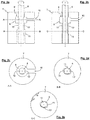
- the adjustment of the opening cross section is based on the Fig. 2a-e clarified.
- the Fig. 2a and b each show a bushing 7 with the stepped bore 5 'introduced therein, which is penetrated by the rotatable shaft 6. Regardless of the angular alignment between the shaft 6 and the bush 7, the viscous material to be applied passes from the inlet 10 into the first annular groove 9.
- the cross-sectional representation AA (FIG. Fig. 2c ) shows that the first annular groove 9 for this purpose has a sufficient distance from the shaft.
- the cross-sectional representation BB ( Fig. 2d ) shows the example setting Fig. 2a in a top view. In the illustrated angular alignment between shaft 6 and bush 7, the opening cross-section is opened and the inlet 10 is hydraulically connected to the outlet.
- Fig. 2b shows in contrast, an angular alignment between the shaft 6 and the bushing 7 in which the grooves 13, 13 'are closed by the lateral surface of the second annular groove 11 (see cross section CC; Fig. 2e ).
- this setting is the hydraulic connection between the inlet 10 and the outlet 4 blocked.
- a clockwise rotation (arrow direction 16) of the shaft 6 acts a gradual enlargement of the opening cross-section and thus of the discharge quantity per unit of time.
- a left turn (arrow 17) of the shaft 6, however, opens the opening cross-section abruptly, so that immediately the maximum opening cross-section and therefore the maximum discharge amount per unit time is available.
Landscapes
- Coating Apparatus (AREA)
Abstract
Description
- Die vorliegende Erfindung betrifft eine Applikationsvorrichtung zum Auftragen von viskosem Material, insbesondere von Kleb- oder Dichtstoffen, mit einem Gehäuse mit einem Einlass für das viskose Material und einer Bohrung, die in einen Auslass für das viskose Material übergeht.
- Mittels derartiger Applikationsvorrichtungen werden üblicherweise lange Klebstoffraupen oder -bahnen auf Werkstücken appliziert, die anschließend mit anderen Werkstücken verbunden werden. Insbesondere in der Automobilindustrie werden Roboter eingesetzt, die Klebstoffraupen mittels solcher Applikationsvorrichtungen auftragen. Vergleichbare Applikationsvorrichtungen sind beispielsweise in
DE 103 45 840 A1 undDE 10 2014 014 592 A1 beschrieben. - Für bestimmte Anwendungszwecke ist es erforderlich, dass die Klebstoffraupe eine unterschiedliche Dicke aufweist, weshalb an bestimmten Stellen eine größere Menge an Klebstoff appliziert werden muss. Hierzu sind im Stand der Technik unterschiedliche Lösungen bekannt, die jedoch nur eine langsame Reaktionszeit bei der Veränderung der Abgabemenge pro Zeiteinheit aufweisen.
- Es ist daher die Aufgabe der vorliegenden Erfindung eine Applikationsvorrichtung für viskoses Material anzugeben, die eine schnelle Änderung der Abgabemenge eines viskosen Materials pro Zeiteinheit erlaubt.
- Diese Aufgabe wird durch die Applikationsvorrichtung nach Anspruch 1 gelöst. Erfindungsgemäß ist die Bohrung des Gehäuses gestuft ausgebildet und weist eine erste Ringnut auf, die mit dem Einlass verbunden ist, sowie eine in Auslassrichtung versetzt angeordnete zweite Ringnut mit einem sich in Umfangsrichtung verändernden Durchmesser, die in den Auslass übergeht, wobei in der Bohrung eine Welle rotierbar gelagert ist, die mindestens eine längsaxial angeordnete Längsnut aufweist, die die erste Ringnut und die zweite Ringnut der Bohrung miteinander verbindet, so dass durch die angulare Ausrichtung der Welle innerhalb der Bohrung ein variabler Öffnungsquerschnitt entsteht. Der Radius beziehungsweise der Durchmesser der zweiten Ringnut ist mit Bezug auf ein Polarkoordinatensystem daher nicht konstant, sondern in Abhängigkeit des Polarwinkels variabel. Durch eine schnell und präzise steuerbare Rotation der Welle lässt sich somit der maßgebliche Öffnungsquerschnitt des Auslasses beziehungsweise der Verbindung zwischen Ein- und Auslass wählbar einstellen, weshalb die Abgabemenge von viskosem Material pro Zeiteinheit schnell und exakt geändert und eingestellt werden kann.
- Bevorzugte Ausführungsformen der vorliegenden Erfindung werden nachfolgend und in den Unteransprüchen angegeben.
- Nach einer ersten bevorzugten Ausgestaltung ist vorgesehen, dass die zweite Ringnut mindestens einen Bereich, vorzugsweise zwei Bereiche aufweist, in denen sich der Abstand zwischen der Welle und der Mantelfläche der Bohrung in radialer Richtung von einem Minimum zu einem Maximum kontinuierlich oder stufenweise vergrößert. Die kontinuierliche oder stufenweise Vergrößerung des Abstands zwischen der Welle und der Mantelfläche der Bohrung und mithin des Öffnungsquerschnitts ermöglicht eine fein einstellbare Änderung der Abgabemenge pro Zeiteinheit bei einer Rotation der Welle in eine Richtung, während eine Rotation in die andere Richtung eine sprunghafte Erhöhung der Abgabemenge pro Zeiteinheit ermöglicht, weil die Nut beziehungsweise die Nuten der Welle unmittelbar in die Position gedreht werden können, die den größten Abstand von der Welle zur Mantelfläche der Bohrung aufweisen. Durch eine Drehung der Welle zwischen entsprechenden Positionen lässt sich die Dicke der applizierten Klebstoffraupe schnell und präzise verändern.
- Vorzugsweise ist vorgesehen, dass in mindestens einer angularen Position der Welle innerhalb der Bohrung die Längsnuten der Welle von der Mantelfläche der ersten und der zweiten Ringnut verschlossen sind, so dass der Öffnungsquerschnitt verschwindet und eine Verbindung zum Auslass gesperrt ist. In dieser Position kann kein viskoses Material von den Längsnuten innerhalb der Welle in die zweite Ringnut eintreten, weshalb die Abgabe von viskosem Material in dieser Position gesperrt ist.
- Ausgehend von dieser angularen Position der Welle gegenüber der zweiten Ringnut lässt sich durch eine Drehung in eine Richtung eine langsame und kontinuierliche Steigerung der Abgabemenge erzielen, während eine kurze Verdrehung in die entgegengesetzte Richtung den Öffnungsquerschnitt sprunghaft vergrößert, weshalb unmittelbar der größte Öffnungsquerschnitt erreicht ist, was die Abgabemenge von viskosem Material pro Zeiteinheit sprunghaft zu einem Maximum führt.
- Die gestufte Bohrung kann unmittelbar innerhalb des Gehäuses eingebracht sein. Alternativ und nach einer bevorzugten Ausführungsform der Erfindung ist vorgesehen, dass die gestufte Bohrung mit der ersten und der zweiten Ringnut in einer Buchse eingebracht ist, die drehfest mit dem Gehäuse der Applikationsvorrichtung verbindbar ist. Eine solche Buchse lässt sich außerhalb des Gehäuses einfach herstellen und ist zudem zu Reinigungszwecken einfach zu demontieren, so dass sich die Verwendung einer Buchse als vorteilhaft erwiesen hat. Damit die Buchse innerhalb des Gehäuses drehfest gelagert ist, ist eine Verdrehsicherung vorgesehen, die beispielsweise in Form einer Madenschraube ausgebildet sein kann, die das Gehäuse der Applikationsvorrichtung durchgreift und in eine Bohrung der Buchse eingreift. Alternativ ist eine Nutführung der Buchse innerhalb der Ausnehmung des Gehäuses vorgesehen, in der die Buchse ruht.
- Zum Antrieb der Welle in beide Drehrichtungen ist vorzugsweise ein Antriebsmotor vorgesehen, wobei zwischen dem Antriebsmotor und der Welle eine Kupplung angeordnet sein kann. Ein solcher Motor ermöglicht die präzise Steuerung der Welle und eine exakte Verdrehung, um den Öffnungsquerschnitt des Auslasses den Vorgaben entsprechend präzise und schnell einzustellen.
- Vorzugsweise ist die Applikationsvorrichtung mit einem Roboterarm verbindbar, so dass die Klebstoffraupe vollautomatisch in der richtigen Position und mit der richtigen Menge an Klebstoff aufgetragen werden kann. Alternativ ist auch vorgesehen, dass die Applikationsvorrichtung handgeführt ist.
- Schließlich ist nach einer bevorzugten Ausführungsform der Erfindung vorgesehen, dass am Auslass der Applikationsvorrichtung eine Düse ausgebildet ist.
- Eine konkrete Ausführungsform der vorliegenden Erfindung wird nachfolgend anhand der Figuren erläutert. Es zeigen:
- Fig. 1
- eine Querschnittsdarstellung einer Applikationsvorrichtung und
- Fig. 2a-e
- Querschnittsdarstellungen einer Buchse.
- Eine konkrete Ausführungsform einer Applikationsvorrichtung 1 ist in
Fig. 1 dargestellt. Die Applikationsvorrichtung 1 besitzt ein Gehäuse 2 mit einer Düse 3, die in einen Auslass 4 übergeht. Das Gehäuse 2 weist eine Bohrung 5 auf, in der eine Welle 6 drehbar gelagert ist. Im dargestellten Ausführungsbeispiel durchgreift die Welle 6 am auslassseitigen Ende des Gehäuses 2 eine gestufte Bohrung 5', die im dargestellten Ausführungsbeispiel innerhalb einer Buchse 7 ausgebildet ist, wobei die Buchse 7 in einer Ausnehmung 8 des Gehäuses 2 drehfest gelagert ist. Zur drehfesten Lagerung der Buchse 7 ist im dargestellten Ausführungsbeispiel eine Madenschraube 18 vorgesehen, die eine Ausnehmung 19 des Gehäuses 2 durchgreift und in eine Bohrung 20 der Buchse 7 eingreift. Die gestufte Bohrung 5' besitzt eine erste Ringnut 9, die mit einem Einlass 10 verbunden ist. Über den Einlass 10 wird viskoses Material mit einer (nicht gezeigten) Zuführeinrichtung dem Gehäuse 2 und mithin der Applikationsvorrichtung 1 zugeführt. Die gestufte Bohrung 5' besitzt eine zweite Ringnut 11, die einen sich über den Umfang verändernden und daher nicht konstanten beziehungsweise variablen Durchmesser aufweist und die unmittelbar in den Auslass 4 übergeht. Zwischen der ersten Ringnut 9 und der zweiten Ringnut 11 ist eine Schulter 12 ausgebildet. Die Welle 6, die die Bohrungen 5, 5' durchgreift, weist im dargestellten Ausführungsbeispiel zwei Längsnuten 13, 13' auf, die eine hydraulische Verbindung zwischen der ersten Ringnut 9 und der zweiten Ringnut 11 schafft. Eine unmittelbare Verbindung zwischen der ersten Ringnut 9 und der zweiten Ringnut 11 ist im Übrigen durch die Schulter 12 blockiert. Durch den variablen Durchmesser der zweiten Ringnut 11 kann mittels einer Rotation der Welle 6 der Öffnungsquerschnitt zur Abgabe des viskosen Materials eingestellt und verändert werden. Dabei ist bei mindestens einer angularen Ausrichtung der Nuten 13, 13' gegenüber der Bohrung 5' vorgesehen, dass der Öffnungsquerschnitt verschwindet und die hydraulische Verbindung zwischen dem Einlass 10 und dem Auslass 4 unterbrochen ist. Von dieser Position ausgehend erlaubt eine Rotation der Welle 6 in eine Richtung eine kontinuierliche Vergrößerung des Öffnungsquerschnitts, während eine Rotation der Welle 6 in die andere Richtung eine sprunghafte Vergrößerung des Öffnungsquerschnitts bewirkt, so dass unmittelbar eine maximale Abgabemenge des viskosen Materials möglich ist. - Zur Steuerung der Welle 6 besitzt die Applikationsvorrichtung 1 einen Antriebsmotor 14, der über eine nicht dargestellte Kupplung mit der Welle 6 verbunden ist. Die Applikationsvorrichtung kann handgeführt sein oder mit einem Roboterarm 15 verbunden sein.
- Die Einstellung des Öffnungsquerschnitts wird anhand der
Fig. 2a-e verdeutlicht. DieFig. 2a und b zeigen jeweils eine Buchse 7 mit der hierin eingebrachten gestuften Bohrung 5', die von der drehbaren Welle 6 durchgriffen wird. Unabhängig von der angularen Ausrichtung zwischen der Welle 6 und der Buchse 7 gelangt das zu applizierende viskose Material von dem Einlass 10 in die erste Ringnut 9. Die Querschnittsdarstellung A-A (Fig. 2c ) zeigt, dass die erste Ringnut 9 hierfür einen ausreichenden Abstand zur Welle aufweist. - Von der ersten Ringnut 9 ausgehend gelangt das viskose Material in die Längsnuten 13, 13', die in die Welle 6 eingebracht sind. Die Querschnittsdarstellung B-B (
Fig. 2d ) zeigt die beispielhafte Einstellung ausFig. 2a in einer Draufsicht. Bei der gezeigten angularen Ausrichtung zwischen Welle 6 und Buchse 7 ist der Öffnungsquerschnitt geöffnet und der Einlass 10 ist mit dem Auslass hydraulisch verbunden. -
Fig. 2b zeigt demgegenüber eine angulare Ausrichtung zwischen der Welle 6 und der Buchse 7 bei der die Nuten 13, 13' von der Mantelfläche der zweiten Ringnut 11 verschlossen sind (vergleiche Querschnitt C-C;Fig. 2e ). Bei dieser Einstellung ist die hydraulische Verbindung zwischen dem Einlass 10 und dem Auslass 4 blockiert. Von dieser Position ausgehend wirkt eine Rechtsdrehung (Pfeilrichtung 16) der Welle 6 eine allmähliche Vergrößerung des Öffnungsquerschnitts und mithin der Abgabemenge pro Zeiteinheit. Eine Linksdrehung (Pfeilrichtung 17) der Welle 6 hingegen öffnet den Öffnungsquerschnitt abrupt, so dass unmittelbar der maximale Öffnungsquerschnitt und mithin die maximale Abgabemenge pro Zeiteinheit zur Verfügung steht.
Claims (7)
- Applikationsvorrichtung zum Auftragen von viskosem Material, insbesondere von Kleb- oder Dichtstoffen, mit einem Gehäuse (2) mit einem Einlass für das viskose Material und einer Bohrung (5'), die in einen Auslass (4) für das viskose Material übergeht,
dadurch gekennzeichnet, dass
die Bohrung (5') gestuft ausgebildet ist und eine erste Ringnut (9) aufweist, die mit dem Einlass (10) verbunden ist, sowie eine in Auslassrichtung versetzt angeordnete zweite Ringnut (11) mit einem sich in Umfangsrichtung verändernden Durchmesser, die in den Auslass (4) übergeht, wobei in der Bohrung (5') eine Welle (6) rotierbar gelagert ist, die mindestens eine längsaxial angeordnete Längsnut (13, 13') aufweist, die die erste Ringnut (9) und die zweite Ringnut (11) der Bohrung (5') miteinander verbindet, so dass durch die angulare Ausrichtung der Welle (6) innerhalb der Bohrung (5') ein variabler Öffnungsquerschnitt entsteht. - Applikationsvorrichtung nach Anspruch 1, dadurch gekennzeichnet, dass die zweite Ringnut (11) mindestens einen Bereich, vorzugsweise zwei Bereiche aufweist, in denen sich der Abstand zwischen der Welle (6) und der Mantelfläche der Bohrung (5') in radialer Richtung von einem Minimum zu einem Maximum kontinuierlich oder stufenweise vergrößert.
- Applikationsvorrichtung nach einem der Ansprüche 1 oder 2, dadurch gekennzeichnet, dass in mindestens einer angularen Position der Welle (6) innerhalb der Bohrung (5') die Längsnuten (13, 13') der Welle von der Mantelfläche der zweiten Ringnut (11) verschlossen sind, so dass der Öffnungsquerschnitt verschwindet und eine Verbindung zum Auslass (4) gesperrt ist.
- Applikationsvorrichtung nach einem der Ansprüche 1 bis 3, dadurch gekennzeichnet, dass die gestufte Bohrung (5') mit der ersten und der zweiten Ringnut (9, 11) in einer Buchse (7) eingebracht ist, die drehfest mit dem Gehäuse (2) der Applikationsvorrichtung (1) verbindbar ist.
- Applikationsvorrichtung nach einem der Ansprüche 1 bis 4, dadurch gekennzeichnet, dass zum Antrieb der Welle (6) in beide Drehrichtungen ein Antriebsmotor (14) vorgesehen ist.
- Applikationsvorrichtung nach einem der Ansprüche 1 bis 5, dadurch gekennzeichnet, dass die Applikationsvorrichtung (1) mit einem Roboterarm (15) verbindbar ist.
- Applikationsvorrichtung nach einem der Ansprüche 1 bis 6, dadurch gekennzeichnet, dass der Auslass (4) als Düse (3) ausgebildet ist.
Applications Claiming Priority (1)
| Application Number | Priority Date | Filing Date | Title |
|---|---|---|---|
| DE102017118942.4A DE102017118942A1 (de) | 2017-08-18 | 2017-08-18 | Applikationsvorrichtung für viskoses Material |
Publications (2)
| Publication Number | Publication Date |
|---|---|
| EP3444039A1 true EP3444039A1 (de) | 2019-02-20 |
| EP3444039B1 EP3444039B1 (de) | 2021-06-16 |
Family
ID=63041830
Family Applications (1)
| Application Number | Title | Priority Date | Filing Date |
|---|---|---|---|
| EP18185100.7A Active EP3444039B1 (de) | 2017-08-18 | 2018-07-24 | Applikationsvorrichtung für viskoses material |
Country Status (3)
| Country | Link |
|---|---|
| EP (1) | EP3444039B1 (de) |
| DE (1) | DE102017118942A1 (de) |
| ES (1) | ES2880365T3 (de) |
Citations (3)
| Publication number | Priority date | Publication date | Assignee | Title |
|---|---|---|---|---|
| US20060027683A1 (en) * | 2004-08-04 | 2006-02-09 | Marcel Puffe | Application head |
| DE102009019192A1 (de) * | 2009-04-28 | 2010-11-11 | I.N.T.-Rickert Gmbh | Kurzraupenpistole |
| DE202017000784U1 (de) * | 2017-02-14 | 2017-02-22 | TÜNKERS-NICKEL Dosiersysteme GmbH | Auftragskopf für mittel- und hochviskose Materialien |
Family Cites Families (3)
| Publication number | Priority date | Publication date | Assignee | Title |
|---|---|---|---|---|
| DE10345840A1 (de) | 2003-09-30 | 2005-04-14 | Sca Schucker Gmbh & Co. Kg | Vorrichtung zum Auftragen eines Fluids |
| DE202012104197U1 (de) * | 2012-11-02 | 2012-11-23 | Nimak Gmbh | Dosierer mit Sicherheitsschließzylinder |
| DE102014014592A1 (de) | 2014-10-07 | 2016-04-07 | Sca Schucker Gmbh & Co. Kg | Vorrichtung zum Auftragen eines viskosen Materials |
-
2017
- 2017-08-18 DE DE102017118942.4A patent/DE102017118942A1/de not_active Withdrawn
-
2018
- 2018-07-24 ES ES18185100T patent/ES2880365T3/es active Active
- 2018-07-24 EP EP18185100.7A patent/EP3444039B1/de active Active
Patent Citations (3)
| Publication number | Priority date | Publication date | Assignee | Title |
|---|---|---|---|---|
| US20060027683A1 (en) * | 2004-08-04 | 2006-02-09 | Marcel Puffe | Application head |
| DE102009019192A1 (de) * | 2009-04-28 | 2010-11-11 | I.N.T.-Rickert Gmbh | Kurzraupenpistole |
| DE202017000784U1 (de) * | 2017-02-14 | 2017-02-22 | TÜNKERS-NICKEL Dosiersysteme GmbH | Auftragskopf für mittel- und hochviskose Materialien |
Also Published As
| Publication number | Publication date |
|---|---|
| EP3444039B1 (de) | 2021-06-16 |
| DE102017118942A1 (de) | 2019-02-21 |
| ES2880365T3 (es) | 2021-11-24 |
Similar Documents
| Publication | Publication Date | Title |
|---|---|---|
| EP1053829A1 (de) | Absaughaube für handgeführten Trennschleifer | |
| EP2114599B1 (de) | Ausgewuchtetes ausbohrwerkzeug mit klemmeinrichtung | |
| EP2995412A1 (de) | Reibrührschweißwerkzeug | |
| DE69305648T2 (de) | Ventil mit voreinstellung | |
| EP3204166B1 (de) | Vorrichtung zum auftragen eines viskosen materials | |
| DE10161356B4 (de) | Schraubgerät | |
| EP0508103B1 (de) | Bohrvorrichtung zum Herstellen von Bohrungen mit Hinterschneidungen | |
| EP0164582A1 (de) | Spannelement zum zentrischen Spannen rotierender Teile | |
| EP0408847A1 (de) | Vorrichtung zum Längs- und Höhenverstellen der Lenksäule eines Kraftfahrzeuges | |
| EP3484630A1 (de) | Applikator zur applikation eines dickstoffs, austauschteil dafür und entsprechendes betriebsverfahren | |
| EP0428496B1 (de) | Verbindung für Bauteile aus unterschiedlichen Materialien | |
| EP3444039B1 (de) | Applikationsvorrichtung für viskoses material | |
| DE69813857T2 (de) | Werkzeug für spanabhebende bearbeitung | |
| DE202013101539U1 (de) | Abstandsjustierelement | |
| DE3401200C2 (de) | ||
| DD297089A5 (de) | Werkzeug fuer den einsatz in werkzeugmaschinen | |
| EP3334636B1 (de) | Klemmvorrichtung einer verstellbaren lenksäule für kraftfahrzeuge | |
| EP1147041B1 (de) | Abschneidventil für hilsfskraftlenkungen, insbesondere für kraftfahrzeuge | |
| EP1427956B1 (de) | Durchflusssteuervorrichtung | |
| EP3658321A1 (de) | Zerspanungswerkzeug | |
| DE10315685B4 (de) | Klemmverbindung für eine fliegend auf einer Motorwelle gelagerte Pumpenwelle | |
| EP3664967B1 (de) | Handwerkzeugmaschine mit einer tiefenanschlageinheit | |
| EP0193085A2 (de) | Auftragevorrichtung zum Auftragen einer zähen Flüssigkeit | |
| WO2005095177A1 (de) | Elektrische servolenkung mit einstellbarem getriebespiel | |
| DE8335033U1 (de) | Kupplungsvorrichtung |
Legal Events
| Date | Code | Title | Description |
|---|---|---|---|
| PUAI | Public reference made under article 153(3) epc to a published international application that has entered the european phase |
Free format text: ORIGINAL CODE: 0009012 |
|
| STAA | Information on the status of an ep patent application or granted ep patent |
Free format text: STATUS: THE APPLICATION HAS BEEN PUBLISHED |
|
| AK | Designated contracting states |
Kind code of ref document: A1 Designated state(s): AL AT BE BG CH CY CZ DE DK EE ES FI FR GB GR HR HU IE IS IT LI LT LU LV MC MK MT NL NO PL PT RO RS SE SI SK SM TR |
|
| AX | Request for extension of the european patent |
Extension state: BA ME |
|
| STAA | Information on the status of an ep patent application or granted ep patent |
Free format text: STATUS: REQUEST FOR EXAMINATION WAS MADE |
|
| 17P | Request for examination filed |
Effective date: 20190710 |
|
| RBV | Designated contracting states (corrected) |
Designated state(s): AL AT BE BG CH CY CZ DE DK EE ES FI FR GB GR HR HU IE IS IT LI LT LU LV MC MK MT NL NO PL PT RO RS SE SI SK SM TR |
|
| 19U | Interruption of proceedings before grant |
Effective date: 20190731 |
|
| 19W | Proceedings resumed before grant after interruption of proceedings |
Effective date: 20200803 |
|
| RAP1 | Party data changed (applicant data changed or rights of an application transferred) |
Owner name: EXEL INDUSTRIES S.A. |
|
| GRAP | Despatch of communication of intention to grant a patent |
Free format text: ORIGINAL CODE: EPIDOSNIGR1 |
|
| STAA | Information on the status of an ep patent application or granted ep patent |
Free format text: STATUS: GRANT OF PATENT IS INTENDED |
|
| INTG | Intention to grant announced |
Effective date: 20210118 |
|
| GRAS | Grant fee paid |
Free format text: ORIGINAL CODE: EPIDOSNIGR3 |
|
| GRAA | (expected) grant |
Free format text: ORIGINAL CODE: 0009210 |
|
| STAA | Information on the status of an ep patent application or granted ep patent |
Free format text: STATUS: THE PATENT HAS BEEN GRANTED |
|
| AK | Designated contracting states |
Kind code of ref document: B1 Designated state(s): AL AT BE BG CH CY CZ DE DK EE ES FI FR GB GR HR HU IE IS IT LI LT LU LV MC MK MT NL NO PL PT RO RS SE SI SK SM TR |
|
| REG | Reference to a national code |
Ref country code: GB Ref legal event code: FG4D Free format text: NOT ENGLISH |
|
| REG | Reference to a national code |
Ref country code: CH Ref legal event code: EP |
|
| REG | Reference to a national code |
Ref country code: DE Ref legal event code: R096 Ref document number: 502018005711 Country of ref document: DE |
|
| REG | Reference to a national code |
Ref country code: AT Ref legal event code: REF Ref document number: 1401884 Country of ref document: AT Kind code of ref document: T Effective date: 20210715 |
|
| REG | Reference to a national code |
Ref country code: IE Ref legal event code: FG4D Free format text: LANGUAGE OF EP DOCUMENT: GERMAN |
|
| REG | Reference to a national code |
Ref country code: LT Ref legal event code: MG9D |
|
| PG25 | Lapsed in a contracting state [announced via postgrant information from national office to epo] |
Ref country code: BG Free format text: LAPSE BECAUSE OF FAILURE TO SUBMIT A TRANSLATION OF THE DESCRIPTION OR TO PAY THE FEE WITHIN THE PRESCRIBED TIME-LIMIT Effective date: 20210916 Ref country code: FI Free format text: LAPSE BECAUSE OF FAILURE TO SUBMIT A TRANSLATION OF THE DESCRIPTION OR TO PAY THE FEE WITHIN THE PRESCRIBED TIME-LIMIT Effective date: 20210616 Ref country code: LT Free format text: LAPSE BECAUSE OF FAILURE TO SUBMIT A TRANSLATION OF THE DESCRIPTION OR TO PAY THE FEE WITHIN THE PRESCRIBED TIME-LIMIT Effective date: 20210616 Ref country code: HR Free format text: LAPSE BECAUSE OF FAILURE TO SUBMIT A TRANSLATION OF THE DESCRIPTION OR TO PAY THE FEE WITHIN THE PRESCRIBED TIME-LIMIT Effective date: 20210616 |
|
| REG | Reference to a national code |
Ref country code: NL Ref legal event code: MP Effective date: 20210616 Ref country code: ES Ref legal event code: FG2A Ref document number: 2880365 Country of ref document: ES Kind code of ref document: T3 Effective date: 20211124 |
|
| PG25 | Lapsed in a contracting state [announced via postgrant information from national office to epo] |
Ref country code: LV Free format text: LAPSE BECAUSE OF FAILURE TO SUBMIT A TRANSLATION OF THE DESCRIPTION OR TO PAY THE FEE WITHIN THE PRESCRIBED TIME-LIMIT Effective date: 20210616 Ref country code: NO Free format text: LAPSE BECAUSE OF FAILURE TO SUBMIT A TRANSLATION OF THE DESCRIPTION OR TO PAY THE FEE WITHIN THE PRESCRIBED TIME-LIMIT Effective date: 20210916 Ref country code: SE Free format text: LAPSE BECAUSE OF FAILURE TO SUBMIT A TRANSLATION OF THE DESCRIPTION OR TO PAY THE FEE WITHIN THE PRESCRIBED TIME-LIMIT Effective date: 20210616 Ref country code: RS Free format text: LAPSE BECAUSE OF FAILURE TO SUBMIT A TRANSLATION OF THE DESCRIPTION OR TO PAY THE FEE WITHIN THE PRESCRIBED TIME-LIMIT Effective date: 20210616 Ref country code: GR Free format text: LAPSE BECAUSE OF FAILURE TO SUBMIT A TRANSLATION OF THE DESCRIPTION OR TO PAY THE FEE WITHIN THE PRESCRIBED TIME-LIMIT Effective date: 20210917 |
|
| PG25 | Lapsed in a contracting state [announced via postgrant information from national office to epo] |
Ref country code: EE Free format text: LAPSE BECAUSE OF FAILURE TO SUBMIT A TRANSLATION OF THE DESCRIPTION OR TO PAY THE FEE WITHIN THE PRESCRIBED TIME-LIMIT Effective date: 20210616 Ref country code: SM Free format text: LAPSE BECAUSE OF FAILURE TO SUBMIT A TRANSLATION OF THE DESCRIPTION OR TO PAY THE FEE WITHIN THE PRESCRIBED TIME-LIMIT Effective date: 20210616 Ref country code: SK Free format text: LAPSE BECAUSE OF FAILURE TO SUBMIT A TRANSLATION OF THE DESCRIPTION OR TO PAY THE FEE WITHIN THE PRESCRIBED TIME-LIMIT Effective date: 20210616 Ref country code: CZ Free format text: LAPSE BECAUSE OF FAILURE TO SUBMIT A TRANSLATION OF THE DESCRIPTION OR TO PAY THE FEE WITHIN THE PRESCRIBED TIME-LIMIT Effective date: 20210616 Ref country code: NL Free format text: LAPSE BECAUSE OF FAILURE TO SUBMIT A TRANSLATION OF THE DESCRIPTION OR TO PAY THE FEE WITHIN THE PRESCRIBED TIME-LIMIT Effective date: 20210616 Ref country code: PT Free format text: LAPSE BECAUSE OF FAILURE TO SUBMIT A TRANSLATION OF THE DESCRIPTION OR TO PAY THE FEE WITHIN THE PRESCRIBED TIME-LIMIT Effective date: 20211018 Ref country code: RO Free format text: LAPSE BECAUSE OF FAILURE TO SUBMIT A TRANSLATION OF THE DESCRIPTION OR TO PAY THE FEE WITHIN THE PRESCRIBED TIME-LIMIT Effective date: 20210616 |
|
| PG25 | Lapsed in a contracting state [announced via postgrant information from national office to epo] |
Ref country code: PL Free format text: LAPSE BECAUSE OF FAILURE TO SUBMIT A TRANSLATION OF THE DESCRIPTION OR TO PAY THE FEE WITHIN THE PRESCRIBED TIME-LIMIT Effective date: 20210616 |
|
| REG | Reference to a national code |
Ref country code: DE Ref legal event code: R097 Ref document number: 502018005711 Country of ref document: DE |
|
| PG25 | Lapsed in a contracting state [announced via postgrant information from national office to epo] |
Ref country code: MC Free format text: LAPSE BECAUSE OF FAILURE TO SUBMIT A TRANSLATION OF THE DESCRIPTION OR TO PAY THE FEE WITHIN THE PRESCRIBED TIME-LIMIT Effective date: 20210616 |
|
| REG | Reference to a national code |
Ref country code: BE Ref legal event code: MM Effective date: 20210731 |
|
| PLBE | No opposition filed within time limit |
Free format text: ORIGINAL CODE: 0009261 |
|
| STAA | Information on the status of an ep patent application or granted ep patent |
Free format text: STATUS: NO OPPOSITION FILED WITHIN TIME LIMIT |
|
| PG25 | Lapsed in a contracting state [announced via postgrant information from national office to epo] |
Ref country code: DK Free format text: LAPSE BECAUSE OF FAILURE TO SUBMIT A TRANSLATION OF THE DESCRIPTION OR TO PAY THE FEE WITHIN THE PRESCRIBED TIME-LIMIT Effective date: 20210616 |
|
| 26N | No opposition filed |
Effective date: 20220317 |
|
| PG25 | Lapsed in a contracting state [announced via postgrant information from national office to epo] |
Ref country code: LU Free format text: LAPSE BECAUSE OF NON-PAYMENT OF DUE FEES Effective date: 20210724 Ref country code: AL Free format text: LAPSE BECAUSE OF FAILURE TO SUBMIT A TRANSLATION OF THE DESCRIPTION OR TO PAY THE FEE WITHIN THE PRESCRIBED TIME-LIMIT Effective date: 20210616 |
|
| PG25 | Lapsed in a contracting state [announced via postgrant information from national office to epo] |
Ref country code: IE Free format text: LAPSE BECAUSE OF NON-PAYMENT OF DUE FEES Effective date: 20210724 Ref country code: BE Free format text: LAPSE BECAUSE OF NON-PAYMENT OF DUE FEES Effective date: 20210731 |
|
| PG25 | Lapsed in a contracting state [announced via postgrant information from national office to epo] |
Ref country code: CY Free format text: LAPSE BECAUSE OF FAILURE TO SUBMIT A TRANSLATION OF THE DESCRIPTION OR TO PAY THE FEE WITHIN THE PRESCRIBED TIME-LIMIT Effective date: 20210616 |
|
| PG25 | Lapsed in a contracting state [announced via postgrant information from national office to epo] |
Ref country code: HU Free format text: LAPSE BECAUSE OF FAILURE TO SUBMIT A TRANSLATION OF THE DESCRIPTION OR TO PAY THE FEE WITHIN THE PRESCRIBED TIME-LIMIT; INVALID AB INITIO Effective date: 20180724 |
|
| PG25 | Lapsed in a contracting state [announced via postgrant information from national office to epo] |
Ref country code: MK Free format text: LAPSE BECAUSE OF FAILURE TO SUBMIT A TRANSLATION OF THE DESCRIPTION OR TO PAY THE FEE WITHIN THE PRESCRIBED TIME-LIMIT Effective date: 20210616 |
|
| REG | Reference to a national code |
Ref country code: AT Ref legal event code: MM01 Ref document number: 1401884 Country of ref document: AT Kind code of ref document: T Effective date: 20230724 |
|
| PG25 | Lapsed in a contracting state [announced via postgrant information from national office to epo] |
Ref country code: MT Free format text: LAPSE BECAUSE OF FAILURE TO SUBMIT A TRANSLATION OF THE DESCRIPTION OR TO PAY THE FEE WITHIN THE PRESCRIBED TIME-LIMIT Effective date: 20210616 |
|
| PG25 | Lapsed in a contracting state [announced via postgrant information from national office to epo] |
Ref country code: AT Free format text: LAPSE BECAUSE OF NON-PAYMENT OF DUE FEES Effective date: 20230724 |
|
| PG25 | Lapsed in a contracting state [announced via postgrant information from national office to epo] |
Ref country code: AT Free format text: LAPSE BECAUSE OF NON-PAYMENT OF DUE FEES Effective date: 20230724 |
|
| PGFP | Annual fee paid to national office [announced via postgrant information from national office to epo] |
Ref country code: ES Payment date: 20250811 Year of fee payment: 8 |
|
| PGFP | Annual fee paid to national office [announced via postgrant information from national office to epo] |
Ref country code: DE Payment date: 20250711 Year of fee payment: 8 |
|
| PGFP | Annual fee paid to national office [announced via postgrant information from national office to epo] |
Ref country code: TR Payment date: 20250711 Year of fee payment: 8 Ref country code: IT Payment date: 20250708 Year of fee payment: 8 |
|
| PGFP | Annual fee paid to national office [announced via postgrant information from national office to epo] |
Ref country code: GB Payment date: 20250723 Year of fee payment: 8 |
|
| PGFP | Annual fee paid to national office [announced via postgrant information from national office to epo] |
Ref country code: FR Payment date: 20250730 Year of fee payment: 8 |
|
| PGFP | Annual fee paid to national office [announced via postgrant information from national office to epo] |
Ref country code: CH Payment date: 20250801 Year of fee payment: 8 |
|
| PGFP | Annual fee paid to national office [announced via postgrant information from national office to epo] |
Ref country code: AT Payment date: 20260410 Year of fee payment: 5 |